WO2011043267A1 - 非水電解質電池 - Google Patents
非水電解質電池 Download PDFInfo
- Publication number
- WO2011043267A1 WO2011043267A1 PCT/JP2010/067265 JP2010067265W WO2011043267A1 WO 2011043267 A1 WO2011043267 A1 WO 2011043267A1 JP 2010067265 W JP2010067265 W JP 2010067265W WO 2011043267 A1 WO2011043267 A1 WO 2011043267A1
- Authority
- WO
- WIPO (PCT)
- Prior art keywords
- layer
- electrode layer
- interface
- negative electrode
- solid electrolyte
- Prior art date
Links
Images


Classifications
-
- H—ELECTRICITY
- H01—ELECTRIC ELEMENTS
- H01M—PROCESSES OR MEANS, e.g. BATTERIES, FOR THE DIRECT CONVERSION OF CHEMICAL ENERGY INTO ELECTRICAL ENERGY
- H01M10/00—Secondary cells; Manufacture thereof
- H01M10/05—Accumulators with non-aqueous electrolyte
- H01M10/052—Li-accumulators
- H01M10/0525—Rocking-chair batteries, i.e. batteries with lithium insertion or intercalation in both electrodes; Lithium-ion batteries
-
- H—ELECTRICITY
- H01—ELECTRIC ELEMENTS
- H01M—PROCESSES OR MEANS, e.g. BATTERIES, FOR THE DIRECT CONVERSION OF CHEMICAL ENERGY INTO ELECTRICAL ENERGY
- H01M10/00—Secondary cells; Manufacture thereof
- H01M10/05—Accumulators with non-aqueous electrolyte
- H01M10/058—Construction or manufacture
- H01M10/0585—Construction or manufacture of accumulators having only flat construction elements, i.e. flat positive electrodes, flat negative electrodes and flat separators
-
- H—ELECTRICITY
- H01—ELECTRIC ELEMENTS
- H01M—PROCESSES OR MEANS, e.g. BATTERIES, FOR THE DIRECT CONVERSION OF CHEMICAL ENERGY INTO ELECTRICAL ENERGY
- H01M10/00—Secondary cells; Manufacture thereof
- H01M10/05—Accumulators with non-aqueous electrolyte
- H01M10/052—Li-accumulators
-
- H—ELECTRICITY
- H01—ELECTRIC ELEMENTS
- H01M—PROCESSES OR MEANS, e.g. BATTERIES, FOR THE DIRECT CONVERSION OF CHEMICAL ENERGY INTO ELECTRICAL ENERGY
- H01M4/00—Electrodes
- H01M4/02—Electrodes composed of, or comprising, active material
- H01M4/13—Electrodes for accumulators with non-aqueous electrolyte, e.g. for lithium-accumulators; Processes of manufacture thereof
- H01M4/131—Electrodes based on mixed oxides or hydroxides, or on mixtures of oxides or hydroxides, e.g. LiCoOx
-
- H—ELECTRICITY
- H01—ELECTRIC ELEMENTS
- H01M—PROCESSES OR MEANS, e.g. BATTERIES, FOR THE DIRECT CONVERSION OF CHEMICAL ENERGY INTO ELECTRICAL ENERGY
- H01M4/00—Electrodes
- H01M4/02—Electrodes composed of, or comprising, active material
- H01M4/13—Electrodes for accumulators with non-aqueous electrolyte, e.g. for lithium-accumulators; Processes of manufacture thereof
- H01M4/134—Electrodes based on metals, Si or alloys
-
- H—ELECTRICITY
- H01—ELECTRIC ELEMENTS
- H01M—PROCESSES OR MEANS, e.g. BATTERIES, FOR THE DIRECT CONVERSION OF CHEMICAL ENERGY INTO ELECTRICAL ENERGY
- H01M4/00—Electrodes
- H01M4/02—Electrodes composed of, or comprising, active material
- H01M4/36—Selection of substances as active materials, active masses, active liquids
- H01M4/362—Composites
- H01M4/366—Composites as layered products
-
- H—ELECTRICITY
- H01—ELECTRIC ELEMENTS
- H01M—PROCESSES OR MEANS, e.g. BATTERIES, FOR THE DIRECT CONVERSION OF CHEMICAL ENERGY INTO ELECTRICAL ENERGY
- H01M10/00—Secondary cells; Manufacture thereof
- H01M10/05—Accumulators with non-aqueous electrolyte
- H01M10/056—Accumulators with non-aqueous electrolyte characterised by the materials used as electrolytes, e.g. mixed inorganic/organic electrolytes
- H01M10/0561—Accumulators with non-aqueous electrolyte characterised by the materials used as electrolytes, e.g. mixed inorganic/organic electrolytes the electrolyte being constituted of inorganic materials only
- H01M10/0562—Solid materials
-
- H—ELECTRICITY
- H01—ELECTRIC ELEMENTS
- H01M—PROCESSES OR MEANS, e.g. BATTERIES, FOR THE DIRECT CONVERSION OF CHEMICAL ENERGY INTO ELECTRICAL ENERGY
- H01M4/00—Electrodes
- H01M4/02—Electrodes composed of, or comprising, active material
- H01M2004/021—Physical characteristics, e.g. porosity, surface area
-
- Y—GENERAL TAGGING OF NEW TECHNOLOGICAL DEVELOPMENTS; GENERAL TAGGING OF CROSS-SECTIONAL TECHNOLOGIES SPANNING OVER SEVERAL SECTIONS OF THE IPC; TECHNICAL SUBJECTS COVERED BY FORMER USPC CROSS-REFERENCE ART COLLECTIONS [XRACs] AND DIGESTS
- Y02—TECHNOLOGIES OR APPLICATIONS FOR MITIGATION OR ADAPTATION AGAINST CLIMATE CHANGE
- Y02E—REDUCTION OF GREENHOUSE GAS [GHG] EMISSIONS, RELATED TO ENERGY GENERATION, TRANSMISSION OR DISTRIBUTION
- Y02E60/00—Enabling technologies; Technologies with a potential or indirect contribution to GHG emissions mitigation
- Y02E60/10—Energy storage using batteries
-
- Y—GENERAL TAGGING OF NEW TECHNOLOGICAL DEVELOPMENTS; GENERAL TAGGING OF CROSS-SECTIONAL TECHNOLOGIES SPANNING OVER SEVERAL SECTIONS OF THE IPC; TECHNICAL SUBJECTS COVERED BY FORMER USPC CROSS-REFERENCE ART COLLECTIONS [XRACs] AND DIGESTS
- Y02—TECHNOLOGIES OR APPLICATIONS FOR MITIGATION OR ADAPTATION AGAINST CLIMATE CHANGE
- Y02P—CLIMATE CHANGE MITIGATION TECHNOLOGIES IN THE PRODUCTION OR PROCESSING OF GOODS
- Y02P70/00—Climate change mitigation technologies in the production process for final industrial or consumer products
- Y02P70/50—Manufacturing or production processes characterised by the final manufactured product
-
- Y—GENERAL TAGGING OF NEW TECHNOLOGICAL DEVELOPMENTS; GENERAL TAGGING OF CROSS-SECTIONAL TECHNOLOGIES SPANNING OVER SEVERAL SECTIONS OF THE IPC; TECHNICAL SUBJECTS COVERED BY FORMER USPC CROSS-REFERENCE ART COLLECTIONS [XRACs] AND DIGESTS
- Y02—TECHNOLOGIES OR APPLICATIONS FOR MITIGATION OR ADAPTATION AGAINST CLIMATE CHANGE
- Y02T—CLIMATE CHANGE MITIGATION TECHNOLOGIES RELATED TO TRANSPORTATION
- Y02T10/00—Road transport of goods or passengers
- Y02T10/60—Other road transportation technologies with climate change mitigation effect
- Y02T10/70—Energy storage systems for electromobility, e.g. batteries
Definitions
- the present invention relates to a nonaqueous electrolyte battery having excellent charge / discharge cycle characteristics.
- Non-aqueous electrolyte batteries are used as power sources for relatively small electric devices such as portable devices.
- a typical example of this non-aqueous electrolyte battery is a lithium ion secondary battery (hereinafter, simply referred to as a lithium secondary battery) using a lithium ion storage / release reaction at the positive and negative electrodes.
- This lithium secondary battery is a battery that performs charge and discharge by exchanging lithium (Li) ions between the positive electrode layer and the negative electrode layer through the electrolyte layer.
- Li lithium
- Patent Document 1 proposes a thin-film battery in which a positive electrode layer, a negative electrode layer, and a solid electrolyte layer are formed by a vapor phase method (for example, a sputtering method or a vapor deposition method).
- a negative electrode layer second electrode
- carbon materials such as graphite and hard carbon, silicon (Si), silicon oxide (SiO x (0 ⁇ x ⁇ 2)), tin alloy, lithium
- a material made of cobalt nitride (LiCoN), Li metal, lithium alloy (for example, LiAl), or the like is used (paragraph 0050 of the document 1).
- the conventional lithium secondary battery as disclosed in Patent Document 1 has a problem that the battery capacity decreases with repeated charge and discharge, and further improvement of charge / discharge cycle characteristics is desired.
- the negative electrode layer is formed of an element such as Si alloyed with Li
- the volume change associated with insertion and extraction of Li ions is large during charge and discharge, and the negative electrode layer is easily peeled off from the solid electrolyte layer.
- the negative electrode layer is formed of Li metal or a lithium alloy
- Li is deposited at the time of charging and Li is dissolved at the time of discharging at the interface between the negative electrode layer and the solid electrolyte layer. It is difficult to maintain the bonding between and the solid electrolyte layer.
- the bonding between the negative electrode layer and the solid electrolyte layer is interrupted, the effective area of the battery is reduced and the battery capacity is reduced.
- the present invention has been made in view of the above circumstances, and one of its purposes is to maintain the bonding between the negative electrode layer and the solid electrolyte layer even when charging and discharging are repeated, and to achieve charge / discharge cycle characteristics.
- the object is to provide an excellent nonaqueous electrolyte battery.
- the present invention solves the above-mentioned problems by providing an interface layer that closely adheres between the negative electrode layer and the solid electrolyte layer and defining the thickness of the interface layer.
- the present invention is a nonaqueous electrolyte battery having a positive electrode layer, a negative electrode layer, and a solid electrolyte layer interposed between the two layers.
- the nonaqueous electrolyte battery of the present invention includes an interface layer between the negative electrode layer and the solid electrolyte layer, the negative electrode layer contains at least Li, and the interface layer contains at least Group 14 elements of the periodic table.
- the thickness of the interface layer is 50 nm or less.
- the interface layer promotes diffusion of Li ions moving from the positive electrode layer to the negative electrode layer during charging into the negative electrode layer.
- the interfacial layer containing Group 14 elements of the periodic table occludes Li ions that have moved from the positive electrode layer through the solid electrolyte layer during charging, and diffuses Li ions into the negative electrode layer (diffusion ability) Is expensive. Therefore, according to the configuration of the present invention, it is difficult for Li to precipitate at the negative electrode layer / solid electrolyte layer interface during charging, and it is possible to prevent the interface between both layers from being expanded.
- the content of Group 14 element in the periodic table in the interface layer is preferably 50% by mass or more, and more preferably 80% by mass or more.
- the thickness of the interface layer is 50 nm or less.
- the interfacial layer itself has better Li ion storage than the Li ion diffusivity of the interface layer into the negative electrode layer, and the volume change of the interface layer becomes larger.
- a preferred interface layer thickness is 20 nm or less.
- the thickness of the interface layer is more than 0, preferably more than 5 nm, more preferably 10 nm or more.
- the thickness of the negative electrode layer is not particularly limited, but is preferably 0.1 ⁇ m to 10 ⁇ m. By satisfy
- a more preferable thickness of the negative electrode layer is 0.5 ⁇ m to 2 ⁇ m.
- the area of the interface layer is preferably not more than the area of the negative electrode layer.
- the area of the interface layer with respect to the negative electrode layer, it is possible to suppress a decrease in battery capacity and maintain a high battery capacity.
- the area of the interface layer is made larger than the area of the negative electrode layer, the area on the opposite side of the interface layer from the face facing the solid electrolyte layer, which is not covered with the negative electrode layer (extrusion area)
- Li ions that have migrated from the positive electrode layer during charging may be reduced and Li may precipitate. This tendency is particularly strong when the area of the positive electrode layer is larger than that of the negative electrode layer. For this reason, since the Li ion which moves between positive and negative electrodes reduces, battery capacity falls.
- the area of the interface layer is smaller than the area of the negative electrode layer. In this case, it is possible to reliably prevent the interface layer from protruding, and the battery capacity due to Li deposition on the surface of the interface layer protruding area. Can be prevented. In addition, if the area of the interface layer is too small relative to the area of the negative electrode layer, it is difficult to obtain the effect of providing the interface layer. Therefore, when the area of the negative electrode layer is Sn and the area of the interface layer is Sb, the ratio of Sn and Sb preferably satisfies 0.4Sn ⁇ Sb.
- the short circuit between the positive and negative electrodes can be suppressed by setting the area of the interface layer to be equal to or less than the area of the negative electrode layer.
- the area of the interface layer is made larger than the area of the negative electrode layer, the distance from the outer edge of the interface layer (extrusion region) to the outer edge of the solid electrolyte layer is correspondingly shorter than the distance from the outer edge of the negative electrode layer to the outer edge of the solid electrolyte layer.
- Li deposited on the surface of the protruding region of the interface layer grows in a whisker shape with repeated charge / discharge, and eventually reaches the outer edge of the solid electrolyte layer along the surface of the solid electrolyte layer.
- Li grown in a whisker shape from the surface of the protruding region of the interface layer reaches the positive electrode layer from the outer edge of the solid electrolyte layer, and may cause a short circuit between the positive and negative electrodes.
- the element contained in the interface layer is Si.
- the interface layer contains Si
- a non-aqueous electrolyte battery having further excellent charge / discharge cycle characteristics can be obtained.
- the interface layer is substantially composed of Si
- a battery having excellent discharge characteristics can be obtained.
- the Ar concentration contained in the interface layer is preferably 1 atomic% or less.
- the present inventors have obtained knowledge that the Ar layer contained in the interface layer can be suppressed to 1 atom% or less, whereby the interface layer can be prevented from being pulverized with repeated charge and discharge. According to this configuration, the effective area of the battery is less likely to decrease due to the pulverization of the interface layer, and the battery capacity is unlikely to decrease.
- the Ar concentration contained in the interface layer is, for example, the Ar concentration in the atmosphere (Ar gas supply amount in the atmosphere), the atmosphere when the interface layer is formed by a vapor phase method in a plasma atmosphere containing Ar. Varies due to pressure and other effects.
- the ratio of Tn and Tb preferably satisfies 0.005 ⁇ Tb / Tn ⁇ 0.5.
- Tb / Tn the ratio of the thickness of the interface layer to the thickness of the negative electrode layer
- Tb / Tn is too small, the effect of providing the interface layer is low, and there is a risk that the junction at the negative electrode layer / solid electrolyte layer interface will be destroyed.
- a more preferable range of Tb / Tn is 0.01 to 0.4.
- the solid electrolyte layer is preferably a sulfide-based solid electrolyte containing at least Li 2 S and P 2 S 5 .
- Examples of the sulfide-based solid electrolyte used for the solid electrolyte layer include Li 2 S-P 2 S 5 system, Li 2 S-SiS 2 system, Li 2 S-B 2 S 3 system, and further P 2 O. 5 or Li 3 PO 4 may be added.
- a sulfide-based solid electrolyte containing Li 2 S and P 2 S 5 is preferable because it exhibits high Li ion conductivity.
- the oxide and sulfide react to increase the interface resistance between the positive electrode layer and the solid electrolyte layer. There is. Therefore, by providing a buffer layer that suppresses the mutual diffusion between the two layers in the vicinity of the interface between the positive electrode layer and the solid electrolyte layer and suppresses the reaction, the interface resistance can be reduced.
- the positive electrode layer is preferably an oxide of lithium and at least one element selected from Mn, Fe, Co, and Ni.
- Such a lithium oxide is representative as a positive electrode active material of a nonaqueous electrolyte battery, and is preferable in securing battery capacity.
- the lithium oxide include LiCoO 2 , LiNiO 2 , LiNi 0.5 Mn 0.5 O 2 , LiCo 0.5 Fe 0.5 O 2 , LiNi 0.5 Mn 1.5 O 4 , LiMn 2 O 4 , LiFePO 4, and the like. You may use a lithium oxide individually or in combination of 2 or more types.
- the nonaqueous electrolyte battery of the present invention includes a specific interface layer between the negative electrode layer and the solid electrolyte layer, thereby preventing peeling between the negative electrode layer and the solid electrolyte layer due to repeated charge and discharge. . As a result, even if charging / discharging is repeated, the battery capacity is unlikely to decrease, and excellent charge / discharge cycle characteristics are exhibited.
- FIG. 6 is a schematic cross-sectional view showing a nonaqueous electrolyte battery of Sample No. 3-3 in Example 3.
- FIG. 6 is a schematic cross-sectional view showing a nonaqueous electrolyte battery of Sample No. 3-6 in Example 3.
- FIG. 6 is a schematic cross-sectional view showing a nonaqueous electrolyte battery of Sample No. 3-6 in Example 3.
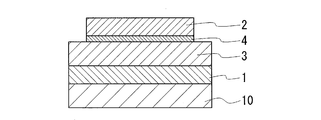
- the basic structure of the nonaqueous electrolyte battery of the present invention is a structure in which a positive electrode layer 1, a solid electrolyte layer 3, and a negative electrode layer 2 are sequentially laminated as shown in FIG. Further, an interface layer 4 that maintains the bonding between the negative electrode layer 2 and the solid electrolyte layer 3 is provided between the negative electrode layer 2 and the solid electrolyte layer 3. Furthermore, the thickness of the interface layer 4 is 50 nm or less.
- Example 1 An all-solid lithium secondary battery having a laminated structure as shown in FIG. 1 was produced, and the battery performance was evaluated.
- ⁇ Battery preparation procedure> By depositing LiCoO 2 on a stainless steel substrate 10 (thickness 0.5 mm, diameter ⁇ 16 mm) using the PLD (pulse laser deposition) method, positive electrode layer 1 (thickness 5 ⁇ m, diameter ⁇ 16 mm) Formed.
- the formation area of the positive electrode layer is adjusted using a mask having the same size as the area of the positive electrode layer to be formed, and the solid electrolyte layer, the interface layer, and the negative electrode layer, which will be described later, are similarly used with an appropriate mask. The formation area is adjusted.
- the substrate on which the LiCoO 2 positive electrode layer was formed was annealed in the atmosphere at 500 ° C. for 3 hours.
- a buffer layer (not shown) was formed on the positive electrode layer 1 by depositing LiNbO 3 using the PLD method.
- the buffer layer had a thickness of 0.02 ⁇ m and a diameter of 16 mm.
- a Li 2 S—P 2 S 5 based solid electrolyte was formed on the buffer layer by using the PLD method, thereby forming a solid electrolyte layer 3 (thickness 10 ⁇ m, diameter ⁇ 16 mm).
- an interface layer 4 (thickness 0.01 ⁇ m (10 nm), diameter ⁇ 10 mm) is formed by depositing Si on the solid electrolyte layer 3 using the PLD method, and further, on the interface layer 4 Then, a negative electrode layer 2 (thickness: 1 ⁇ m, diameter: ⁇ 10 mm) was formed by depositing Li using a vacuum deposition method.
- the laminate was accommodated in a coin-type case, and a coin-type all-solid lithium secondary battery was completed.
- the positive electrode layer, the buffer layer, the solid electrolyte layer, the interface layer, and the negative electrode layer are formed so as to overlap each other on a concentric axis when viewed in plan.
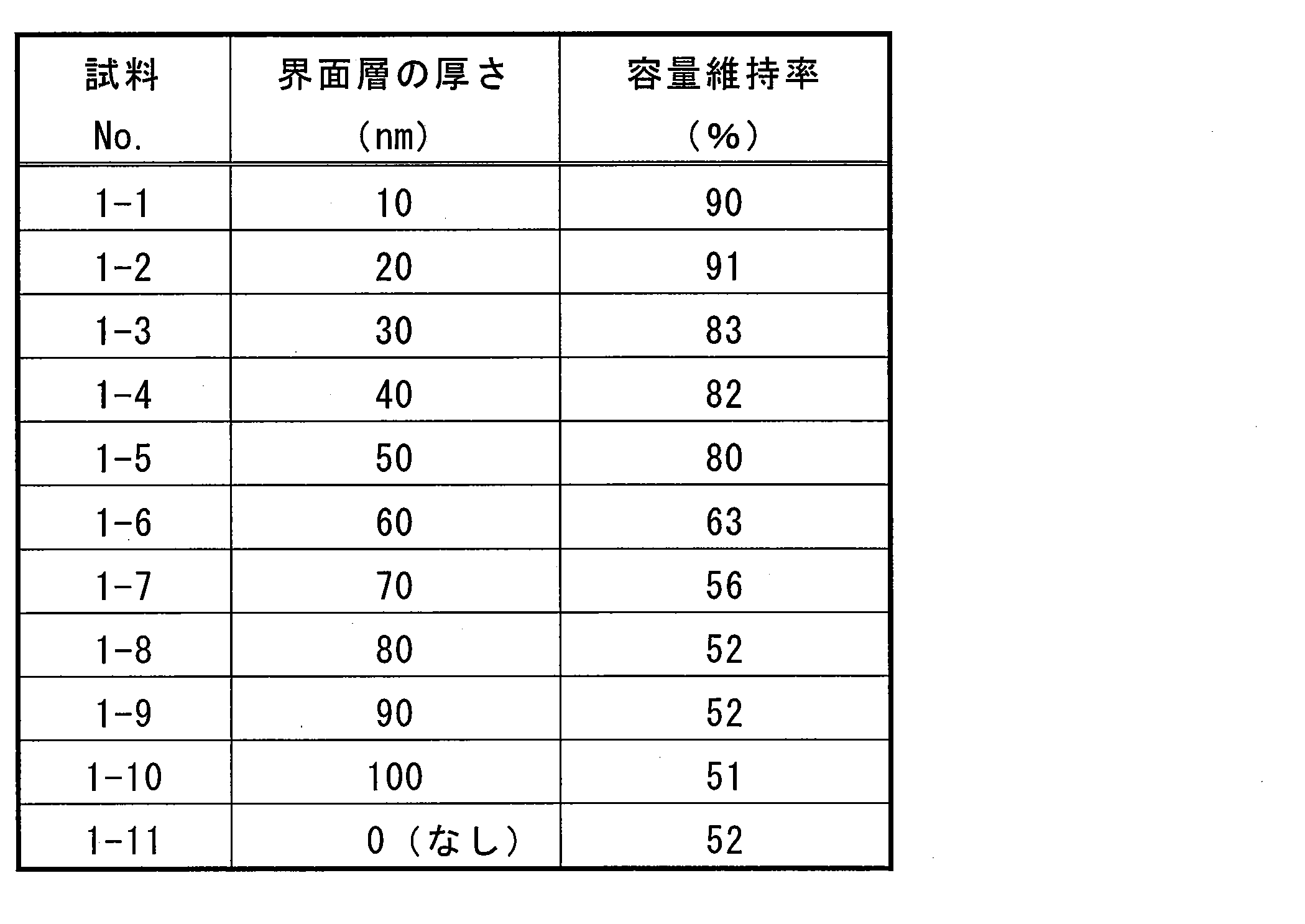
- samples No.1-1 to No.1-5 whose interface layer thickness is 0.05 ⁇ m (50 nm) or less have a capacity retention rate of 100% or more after 100 cycles. It can be seen that the cycle characteristics are excellent.
- Sample No.1-1 to No.1-2 whose interface layer thickness is 0.02 ⁇ m (20nm) or less, has a capacity retention rate of 90% or more after 100 cycles and more charge / discharge cycle characteristics. It can be seen that it has improved.
- Sample Nos. 1-6 to 1-10 with an interface layer thickness of 60 nm or more, and Sample No. 1-11 without an interface layer have a low capacity retention rate after 100 cycles. It turns out that it is inferior to charging / discharging cycling characteristics.
- Example 2 An all-solid lithium secondary battery having a laminated structure was produced in the same manner as in Example 1 except that the Ar concentration in the interface layer was controlled, and the battery performance was evaluated.
- a positive electrode layer (thickness 1 ⁇ m) was formed by depositing LiCoO 2 on a stainless steel substrate (thickness 100 ⁇ m) using a sputtering method. After the film formation, the substrate on which the LiCoO 2 positive electrode layer was formed was annealed in the atmosphere at 500 ° C. for 3 hours.
- a buffer layer (thickness 20 nm) was formed on the positive electrode layer by depositing LiNbO 3 using the PLD method.
- a Li 2 S—P 2 S 5 based solid electrolyte was formed on the buffer layer using a vacuum deposition method to form a solid electrolyte layer (thickness 5 ⁇ m).
- an Si layer is formed on the solid electrolyte layer using a sputtering method to form an interface layer (thickness 20 nm). Further, Li is formed on the interface layer using a vacuum deposition method. By forming a film, a negative electrode layer (thickness 1 ⁇ m) was formed.
- the film when forming the interface layer made of Si, the film was formed in a plasma containing Ar. Specifically, after vacuuming the film formation chamber to 3 ⁇ 10 ⁇ 3 Pa, Ar gas was supplied into the film formation chamber, and the atmospheric pressure during film formation was adjusted to 0.4 Pa. Then, 1 kW of electric power was applied to generate Ar plasma, and a Si target was sputtered to form Si (interface layer) containing Ar on the solid electrolyte layer.
- the laminate was accommodated in a coin-type case, and a coin-type all-solid lithium secondary battery was completed.
- the positive electrode layer, the buffer layer, the solid electrolyte layer, the interface layer, and the negative electrode layer are formed to have the same area.
- sample Nos. 2-1 to 2-3 whose Ar concentration in the interface layer is 1.0 atomic% or less, have a capacity retention rate of 80% or more after 100 cycles and an Ar concentration of 1.5 atoms. It can be seen that the charge / discharge cycle characteristics are excellent compared to No. 2-4 of%. This is considered that when the Ar concentration in the interface layer is 1 atomic% or less, it was possible to suppress the pulverization of the interface layer due to repeated charge and discharge, and as a result, it was possible to suppress the decrease in battery capacity. .
- Example 3 An all-solid lithium secondary battery having a laminated structure was produced in the same manner as in Example 1 except that the formation area of the interface layer was controlled, and the battery performance was evaluated.
- ⁇ Battery preparation procedure> By depositing LiCoO 2 on a stainless steel substrate 10 (thickness 0.5 mm, diameter ⁇ 16 mm) using the PLD (pulse laser deposition) method, positive electrode layer 1 (thickness 5 ⁇ m, diameter ⁇ 16 mm) Formed. After the film formation, the substrate on which the LiCoO 2 positive electrode layer was formed was annealed in the atmosphere at 500 ° C. for 3 hours.
- a buffer layer (not shown) was formed on the positive electrode layer 1 by depositing LiNbO 3 using the PLD method.
- the buffer layer had a thickness of 0.02 ⁇ m and a diameter of 16 mm.
- a Li 2 S—P 2 S 5 -based solid electrolyte was formed on the buffer layer using the PLD method to form a solid electrolyte layer 3 (thickness 5 ⁇ m, diameter ⁇ 16 mm).
- an interface layer 4 (thickness 0.03 ⁇ m, diameter ⁇ 4 mm) is formed by depositing Si on the solid electrolyte layer 3 using the PLD method, and further, vacuum deposition is performed on the interface layer 4
- the negative electrode layer 2 (thickness 1 ⁇ m, diameter ⁇ 10 mm) was formed by depositing Li using the method.
- the ratio (Tb / Tn) between the thickness Tn of the negative electrode layer 2 and the thickness Tb of the interface layer 4 is 0.03.
- the laminate was accommodated in a coin-type case, and a coin-type all-solid lithium secondary battery was completed.
- the positive electrode layer, the buffer layer, the solid electrolyte layer, the interface layer, and the negative electrode layer are formed so as to overlap each other on a concentric axis when viewed in plan.
- Sample No. 3-3 has a structure as shown in FIG. 2, and the area of the interface layer is equal to or less than the area of the negative electrode layer. More specifically, the ratio of the area Sn of the negative electrode layer to the area Sb of the interface layer is Sb ⁇ It satisfies Sn and is formed so that the interface layer does not protrude from the outer shape of the negative electrode layer when viewed in plan.
- Sample No. 3-6 has a structure as shown in FIG. 3, and the interface layer protrudes from the outer shape of the negative electrode layer when viewed in plan (Sb> Sn). There is an uncovered protruding area (indicated by reference numeral 41 in FIG. 3).
- the thickness Tn of the negative electrode layer and the thickness Tb of the interface layer are the maximum thicknesses as shown in FIGS.
- Sample Nos. 3-1 to 3-3 have a capacity retention rate of 90% or more after 10 cycles and are excellent in charge / discharge cycle characteristics.
- Samples No. 3-5 and No. 3-6 have a low capacity retention rate after 10 cycles and are inferior in charge / discharge cycle characteristics. This is probably because Li was deposited on the surface of the protruding region of the interface layer as a result of repeated charge and discharge, leading to a decrease in capacity.
- the present invention is not limited to the above-described embodiment, and can be appropriately changed without departing from the gist of the present invention.
- the thickness and area of the interface layer may be changed as appropriate.
- C, Ge, Sn, and Pb, which are Group 14 elements of the same periodic table as Si, may be used for the interface layer. Since these elements also have the ability to occlude Li ions that have migrated from the positive electrode layer during charging and diffuse them into the negative electrode layer, it is considered that the same effect as Si can be expected.
- the non-aqueous electrolyte battery of the present invention can be suitably used as a power source for an electric vehicle as well as a mobile phone, a notebook computer, a digital camera.
Abstract
Description
図1に示すような積層構造の全固体リチウム二次電池を作製し、その電池性能を評価した。
ステンレス製の基材10(厚さ0.5mm、直径φ16mm)の上に、PLD(パルスレーザデポジション)法を用いてLiCoO2を成膜することで、正極層1(厚さ5μm、直径φ16mm)を形成した。なお、正極層の形成面積は、形成しようとする正極層の面積と同じサイズのマスクを用いて調節しており、後述する固体電解質層、界面層及び負極層も同様に、適宜なマスクを用いて形成面積を調節している。また成膜後、LiCoO2の正極層が形成された基材を、大気中500℃で3時間のアニール処理を行った。
界面層中のAr濃度を制御した以外は、実施例1と同様にして、積層構造の全固体リチウム二次電池を作製し、その電池性能を評価した。
ステンレス製の基材(厚さ100μm)の上に、スパッタリング法を用いてLiCoO2を成膜することで、正極層(厚さ1μm)を形成した。また成膜後、LiCoO2の正極層が形成された基材を、大気中500℃で3時間のアニール処理を行った。

界面層の形成面積を制御した以外は、実施例1と同様にして、積層構造の全固体リチウム二次電池を作製し、その電池性能を評価した。
ステンレス製の基材10(厚さ0.5mm、直径φ16mm)の上に、PLD(パルスレーザデポジション)法を用いてLiCoO2を成膜することで、正極層1(厚さ5μm、直径φ16mm)を形成した。また成膜後、LiCoO2の正極層が形成された基材を、大気中500℃で3時間のアニール処理を行った。

2 負極層
3 固体電解質層
4 界面層(Si膜)
41 はみ出し領域
10 基材
Claims (9)
- 正極層と負極層、及びこれら両層の間に介在される固体電解質層を有する非水電解質電池であって、
前記負極層と前記固体電解質層との間に界面層を備え、
前記負極層は、Liを含有し、
前記界面層は、周期律表第14族元素を含有し、
前記界面層の厚さが、50nm以下であることを特徴とする非水電解質電池。 - 平面視したとき、前記界面層の面積が、前記負極層の面積以下であることを特徴とする請求項1に記載の非水電解質電池。
- 前記界面層に含有する元素が、Siであることを特徴とする請求項1又は2に記載の非水電解質電池。
- 前記界面層が、実質的にSiからなることを特徴とする請求項1又は2に記載の非水電解質電池。
- 前記界面層中に含まれるAr濃度が1原子%以下であることを特徴とする請求項1又は2に記載の非水電解質電池。
- 前記負極層の厚さをTn、前記界面層の厚さをTbとした場合、TnとTbとの比が、0.005<Tb/Tn<0.5を満たすことを特徴とする請求項1又は2に記載の非水電解質電池。
- 前記固体電解質層が、Li2SとP2S5を含む硫化物系固体電解質であることを特徴とする請求項1又は2に記載の非水電解質電池。
- 前記正極層と前記固体電解質層との間に、これら両層の界面抵抗を低減する緩衝層を備えることを特徴とする請求項1又は2に記載の非水電解質電池。
- 前記正極層が、Mn、Fe、Co及びNiから選択される少なくとも一種の元素とリチウムとの酸化物であることを特徴とする請求項1又は2に記載の非水電解質電池。
Priority Applications (4)
| Application Number | Priority Date | Filing Date | Title |
|---|---|---|---|
| JP2011535370A JPWO2011043267A1 (ja) | 2009-10-05 | 2010-10-01 | 非水電解質電池 |
| US13/497,063 US20120177998A1 (en) | 2009-10-05 | 2010-10-01 | Nonaqueous electrolyte battery |
| CN2010800445128A CN102576909A (zh) | 2009-10-05 | 2010-10-01 | 非水电解质电池 |
| EP10821938.7A EP2472665A4 (en) | 2009-10-05 | 2010-10-01 | NONAQUEOUS ELECTROLYTE BATTERY |
Applications Claiming Priority (6)
| Application Number | Priority Date | Filing Date | Title |
|---|---|---|---|
| JP2009-231909 | 2009-10-05 | ||
| JP2009231910 | 2009-10-05 | ||
| JP2009231909 | 2009-10-05 | ||
| JP2009-231910 | 2009-10-05 | ||
| JP2010-001355 | 2010-01-06 | ||
| JP2010001355 | 2010-01-06 |
Publications (1)
| Publication Number | Publication Date |
|---|---|
| WO2011043267A1 true WO2011043267A1 (ja) | 2011-04-14 |
Family
ID=43856725
Family Applications (1)
| Application Number | Title | Priority Date | Filing Date |
|---|---|---|---|
| PCT/JP2010/067265 WO2011043267A1 (ja) | 2009-10-05 | 2010-10-01 | 非水電解質電池 |
Country Status (6)
| Country | Link |
|---|---|
| US (1) | US20120177998A1 (ja) |
| EP (1) | EP2472665A4 (ja) |
| JP (1) | JPWO2011043267A1 (ja) |
| KR (1) | KR20120093833A (ja) |
| CN (1) | CN102576909A (ja) |
| WO (1) | WO2011043267A1 (ja) |
Cited By (2)
| Publication number | Priority date | Publication date | Assignee | Title |
|---|---|---|---|---|
| JP2011060471A (ja) * | 2009-09-08 | 2011-03-24 | Nec Energy Devices Ltd | 非水系電解質二次電池 |
| JP2020512663A (ja) * | 2017-03-30 | 2020-04-23 | インターナショナル・ビジネス・マシーンズ・コーポレーションInternational Business Machines Corporation | 固体リチウム・ベースの電池および固体リチウム・ベースの電池を形成する方法 |
Families Citing this family (7)
| Publication number | Priority date | Publication date | Assignee | Title |
|---|---|---|---|---|
| FR3010832B1 (fr) * | 2013-09-16 | 2017-12-15 | Commissariat Energie Atomique | Procede de realisation d'une microbatterie au lithium |
| WO2019136467A1 (en) * | 2018-01-08 | 2019-07-11 | 24M Technologies, Inc. | Electrochemical cells including selectively permeable membranes, systems and methods of manufacturing the same |
| US11069920B2 (en) * | 2019-02-25 | 2021-07-20 | Ford Global Technologies, Llc | Solid state battery design with mixed ionic and electronic conductor |
| CN109768318A (zh) * | 2019-03-12 | 2019-05-17 | 浙江锋锂新能源科技有限公司 | 一种混合固液电解质锂蓄电池 |
| US11631920B2 (en) | 2019-06-27 | 2023-04-18 | 24M Technologies, Inc. | Dual electrolyte electrochemical cells, systems, and methods of manufacturing the same |
| KR20220060186A (ko) * | 2020-11-04 | 2022-05-11 | 주식회사 엘지에너지솔루션 | 음극보다 면적이 넓은 양극을 포함하는 전고체전지 및 이의 제조방법 |
| KR20230149638A (ko) * | 2022-04-20 | 2023-10-27 | 삼성에스디아이 주식회사 | 전고체 이차 전지 및 이의 제조 방법 |
Citations (4)
| Publication number | Priority date | Publication date | Assignee | Title |
|---|---|---|---|---|
| JP2943127B2 (ja) * | 1992-11-30 | 1999-08-30 | キヤノン株式会社 | 二次電池 |
| JP2004206942A (ja) * | 2002-12-24 | 2004-07-22 | Ion Engineering Research Institute Corp | 全固体リチウム電池 |
| JP2004281316A (ja) * | 2003-03-18 | 2004-10-07 | Matsushita Electric Ind Co Ltd | 固体電解質電池 |
| JP2009193803A (ja) * | 2008-02-14 | 2009-08-27 | Toyota Motor Corp | 全固体リチウム二次電池 |
Family Cites Families (7)
| Publication number | Priority date | Publication date | Assignee | Title |
|---|---|---|---|---|
| DE3838329A1 (de) * | 1987-11-11 | 1989-05-24 | Ricoh Kk | Negative elektrode fuer sekundaerbatterie |
| CA2110097C (en) * | 1992-11-30 | 2002-07-09 | Soichiro Kawakami | Secondary battery |
| JP4997674B2 (ja) * | 2001-09-03 | 2012-08-08 | 日本電気株式会社 | 二次電池用負極および二次電池 |
| EP1465269B1 (en) * | 2003-04-03 | 2012-08-01 | Panasonic Corporation | Electrode and electrochemical device using the same |
| JP3707617B2 (ja) * | 2003-05-20 | 2005-10-19 | ソニー株式会社 | 負極およびそれを用いた電池 |
| KR100878718B1 (ko) * | 2007-08-28 | 2009-01-14 | 한국과학기술연구원 | 리튬이차전지용 실리콘 박막 음극, 이의 제조방법 및 이를포함하는 리튬이차전지 |
| JP5151692B2 (ja) * | 2007-09-11 | 2013-02-27 | 住友電気工業株式会社 | リチウム電池 |
-
2010
- 2010-10-01 KR KR1020127005915A patent/KR20120093833A/ko not_active Application Discontinuation
- 2010-10-01 CN CN2010800445128A patent/CN102576909A/zh active Pending
- 2010-10-01 US US13/497,063 patent/US20120177998A1/en not_active Abandoned
- 2010-10-01 JP JP2011535370A patent/JPWO2011043267A1/ja active Pending
- 2010-10-01 EP EP10821938.7A patent/EP2472665A4/en not_active Withdrawn
- 2010-10-01 WO PCT/JP2010/067265 patent/WO2011043267A1/ja active Application Filing
Patent Citations (4)
| Publication number | Priority date | Publication date | Assignee | Title |
|---|---|---|---|---|
| JP2943127B2 (ja) * | 1992-11-30 | 1999-08-30 | キヤノン株式会社 | 二次電池 |
| JP2004206942A (ja) * | 2002-12-24 | 2004-07-22 | Ion Engineering Research Institute Corp | 全固体リチウム電池 |
| JP2004281316A (ja) * | 2003-03-18 | 2004-10-07 | Matsushita Electric Ind Co Ltd | 固体電解質電池 |
| JP2009193803A (ja) * | 2008-02-14 | 2009-08-27 | Toyota Motor Corp | 全固体リチウム二次電池 |
Cited By (3)
| Publication number | Priority date | Publication date | Assignee | Title |
|---|---|---|---|---|
| JP2011060471A (ja) * | 2009-09-08 | 2011-03-24 | Nec Energy Devices Ltd | 非水系電解質二次電池 |
| JP2020512663A (ja) * | 2017-03-30 | 2020-04-23 | インターナショナル・ビジネス・マシーンズ・コーポレーションInternational Business Machines Corporation | 固体リチウム・ベースの電池および固体リチウム・ベースの電池を形成する方法 |
| JP7059299B2 (ja) | 2017-03-30 | 2022-04-25 | インターナショナル・ビジネス・マシーンズ・コーポレーション | 固体リチウム・ベースの電池および固体リチウム・ベースの電池を形成する方法 |
Also Published As
| Publication number | Publication date |
|---|---|
| EP2472665A4 (en) | 2014-04-23 |
| JPWO2011043267A1 (ja) | 2013-03-04 |
| EP2472665A1 (en) | 2012-07-04 |
| KR20120093833A (ko) | 2012-08-23 |
| US20120177998A1 (en) | 2012-07-12 |
| CN102576909A (zh) | 2012-07-11 |
Similar Documents
| Publication | Publication Date | Title |
|---|---|---|
| WO2011043267A1 (ja) | 非水電解質電池 | |
| JP5151692B2 (ja) | リチウム電池 | |
| JP5316809B2 (ja) | リチウム電池およびその製造方法 | |
| JP5348607B2 (ja) | 全固体リチウム二次電池 | |
| JP5217195B2 (ja) | 薄膜固体リチウムイオン二次電池及びこれを備えた複合型機器 | |
| WO2010021205A1 (ja) | 非水電解質二次電池及びその製造方法 | |
| JP5310996B2 (ja) | リチウム電池 | |
| JP2011086554A (ja) | 非水電解質電池 | |
| JP2004171874A (ja) | 負極およびそれを用いた電池 | |
| KR20180101729A (ko) | 코팅된 전해질을 갖는 리튬-이온 배터리 | |
| WO2012099178A1 (ja) | 非水電解質電池 | |
| JP2012014892A (ja) | 非水電解質電池 | |
| JP2009277381A (ja) | リチウム電池 | |
| JP5217455B2 (ja) | リチウム電池、及びリチウム電池の製造方法 | |
| US20130065134A1 (en) | Nonaqueous-electrolyte battery and method for producing the same | |
| Liang et al. | Research progress of all solid-state thin film lithium Battery | |
| JP2009199920A (ja) | リチウム電池 | |
| JP2011044368A (ja) | 非水電解質電池 | |
| JP2009152077A (ja) | リチウム電池 | |
| US20120231345A1 (en) | Nonaqueous electrolyte battery and solid electrolyte for nonaqueous electrolyte battery | |
| JP2012054151A (ja) | 固体電解質電池 | |
| JP2011113735A (ja) | 非水電解質電池 | |
| JP2011159467A (ja) | 非水電解質電池 | |
| JP2012160324A (ja) | 非水電解質電池 | |
| JP7025308B2 (ja) | リチウムイオン二次電池 |
Legal Events
| Date | Code | Title | Description |
|---|---|---|---|
| WWE | Wipo information: entry into national phase |
Ref document number: 201080044512.8 Country of ref document: CN |
|
| 121 | Ep: the epo has been informed by wipo that ep was designated in this application |
Ref document number: 10821938 Country of ref document: EP Kind code of ref document: A1 |
|
| ENP | Entry into the national phase |
Ref document number: 2011535370 Country of ref document: JP Kind code of ref document: A |
|
| ENP | Entry into the national phase |
Ref document number: 20127005915 Country of ref document: KR Kind code of ref document: A |
|
| WWE | Wipo information: entry into national phase |
Ref document number: 13497063 Country of ref document: US |
|
| WWE | Wipo information: entry into national phase |
Ref document number: 2010821938 Country of ref document: EP |
|
| NENP | Non-entry into the national phase |
Ref country code: DE |