WO2018181275A1 - Procédé de production d'objet moulé tridimensionnel - Google Patents
Procédé de production d'objet moulé tridimensionnel Download PDFInfo
- Publication number
- WO2018181275A1 WO2018181275A1 PCT/JP2018/012355 JP2018012355W WO2018181275A1 WO 2018181275 A1 WO2018181275 A1 WO 2018181275A1 JP 2018012355 W JP2018012355 W JP 2018012355W WO 2018181275 A1 WO2018181275 A1 WO 2018181275A1
- Authority
- WO
- WIPO (PCT)
- Prior art keywords
- dimensional structure
- composition
- layer
- particles
- forming
- Prior art date
Links
Images


Classifications
-
- B—PERFORMING OPERATIONS; TRANSPORTING
- B29—WORKING OF PLASTICS; WORKING OF SUBSTANCES IN A PLASTIC STATE IN GENERAL
- B29C—SHAPING OR JOINING OF PLASTICS; SHAPING OF MATERIAL IN A PLASTIC STATE, NOT OTHERWISE PROVIDED FOR; AFTER-TREATMENT OF THE SHAPED PRODUCTS, e.g. REPAIRING
- B29C64/00—Additive manufacturing, i.e. manufacturing of three-dimensional [3D] objects by additive deposition, additive agglomeration or additive layering, e.g. by 3D printing, stereolithography or selective laser sintering
- B29C64/10—Processes of additive manufacturing
- B29C64/141—Processes of additive manufacturing using only solid materials
- B29C64/153—Processes of additive manufacturing using only solid materials using layers of powder being selectively joined, e.g. by selective laser sintering or melting
-
- B—PERFORMING OPERATIONS; TRANSPORTING
- B22—CASTING; POWDER METALLURGY
- B22F—WORKING METALLIC POWDER; MANUFACTURE OF ARTICLES FROM METALLIC POWDER; MAKING METALLIC POWDER; APPARATUS OR DEVICES SPECIALLY ADAPTED FOR METALLIC POWDER
- B22F1/00—Metallic powder; Treatment of metallic powder, e.g. to facilitate working or to improve properties
- B22F1/10—Metallic powder containing lubricating or binding agents; Metallic powder containing organic material
- B22F1/103—Metallic powder containing lubricating or binding agents; Metallic powder containing organic material containing an organic binding agent comprising a mixture of, or obtained by reaction of, two or more components other than a solvent or a lubricating agent
-
- B—PERFORMING OPERATIONS; TRANSPORTING
- B22—CASTING; POWDER METALLURGY
- B22F—WORKING METALLIC POWDER; MANUFACTURE OF ARTICLES FROM METALLIC POWDER; MAKING METALLIC POWDER; APPARATUS OR DEVICES SPECIALLY ADAPTED FOR METALLIC POWDER
- B22F10/00—Additive manufacturing of workpieces or articles from metallic powder
- B22F10/20—Direct sintering or melting
- B22F10/28—Powder bed fusion, e.g. selective laser melting [SLM] or electron beam melting [EBM]
-
- B—PERFORMING OPERATIONS; TRANSPORTING
- B28—WORKING CEMENT, CLAY, OR STONE
- B28B—SHAPING CLAY OR OTHER CERAMIC COMPOSITIONS; SHAPING SLAG; SHAPING MIXTURES CONTAINING CEMENTITIOUS MATERIAL, e.g. PLASTER
- B28B1/00—Producing shaped prefabricated articles from the material
- B28B1/001—Rapid manufacturing of 3D objects by additive depositing, agglomerating or laminating of material
-
- B—PERFORMING OPERATIONS; TRANSPORTING
- B33—ADDITIVE MANUFACTURING TECHNOLOGY
- B33Y—ADDITIVE MANUFACTURING, i.e. MANUFACTURING OF THREE-DIMENSIONAL [3-D] OBJECTS BY ADDITIVE DEPOSITION, ADDITIVE AGGLOMERATION OR ADDITIVE LAYERING, e.g. BY 3-D PRINTING, STEREOLITHOGRAPHY OR SELECTIVE LASER SINTERING
- B33Y10/00—Processes of additive manufacturing
-
- B—PERFORMING OPERATIONS; TRANSPORTING
- B33—ADDITIVE MANUFACTURING TECHNOLOGY
- B33Y—ADDITIVE MANUFACTURING, i.e. MANUFACTURING OF THREE-DIMENSIONAL [3-D] OBJECTS BY ADDITIVE DEPOSITION, ADDITIVE AGGLOMERATION OR ADDITIVE LAYERING, e.g. BY 3-D PRINTING, STEREOLITHOGRAPHY OR SELECTIVE LASER SINTERING
- B33Y30/00—Apparatus for additive manufacturing; Details thereof or accessories therefor
-
- C—CHEMISTRY; METALLURGY
- C09—DYES; PAINTS; POLISHES; NATURAL RESINS; ADHESIVES; COMPOSITIONS NOT OTHERWISE PROVIDED FOR; APPLICATIONS OF MATERIALS NOT OTHERWISE PROVIDED FOR
- C09D—COATING COMPOSITIONS, e.g. PAINTS, VARNISHES OR LACQUERS; FILLING PASTES; CHEMICAL PAINT OR INK REMOVERS; INKS; CORRECTING FLUIDS; WOODSTAINS; PASTES OR SOLIDS FOR COLOURING OR PRINTING; USE OF MATERIALS THEREFOR
- C09D11/00—Inks
- C09D11/02—Printing inks
- C09D11/03—Printing inks characterised by features other than the chemical nature of the binder
- C09D11/037—Printing inks characterised by features other than the chemical nature of the binder characterised by the pigment
-
- C—CHEMISTRY; METALLURGY
- C09—DYES; PAINTS; POLISHES; NATURAL RESINS; ADHESIVES; COMPOSITIONS NOT OTHERWISE PROVIDED FOR; APPLICATIONS OF MATERIALS NOT OTHERWISE PROVIDED FOR
- C09D—COATING COMPOSITIONS, e.g. PAINTS, VARNISHES OR LACQUERS; FILLING PASTES; CHEMICAL PAINT OR INK REMOVERS; INKS; CORRECTING FLUIDS; WOODSTAINS; PASTES OR SOLIDS FOR COLOURING OR PRINTING; USE OF MATERIALS THEREFOR
- C09D11/00—Inks
- C09D11/30—Inkjet printing inks
- C09D11/32—Inkjet printing inks characterised by colouring agents
- C09D11/322—Pigment inks
-
- B—PERFORMING OPERATIONS; TRANSPORTING
- B22—CASTING; POWDER METALLURGY
- B22F—WORKING METALLIC POWDER; MANUFACTURE OF ARTICLES FROM METALLIC POWDER; MAKING METALLIC POWDER; APPARATUS OR DEVICES SPECIALLY ADAPTED FOR METALLIC POWDER
- B22F10/00—Additive manufacturing of workpieces or articles from metallic powder
- B22F10/30—Process control
- B22F10/36—Process control of energy beam parameters
-
- B—PERFORMING OPERATIONS; TRANSPORTING
- B22—CASTING; POWDER METALLURGY
- B22F—WORKING METALLIC POWDER; MANUFACTURE OF ARTICLES FROM METALLIC POWDER; MAKING METALLIC POWDER; APPARATUS OR DEVICES SPECIALLY ADAPTED FOR METALLIC POWDER
- B22F10/00—Additive manufacturing of workpieces or articles from metallic powder
- B22F10/40—Structures for supporting workpieces or articles during manufacture and removed afterwards
- B22F10/43—Structures for supporting workpieces or articles during manufacture and removed afterwards characterised by material
-
- B—PERFORMING OPERATIONS; TRANSPORTING
- B22—CASTING; POWDER METALLURGY
- B22F—WORKING METALLIC POWDER; MANUFACTURE OF ARTICLES FROM METALLIC POWDER; MAKING METALLIC POWDER; APPARATUS OR DEVICES SPECIALLY ADAPTED FOR METALLIC POWDER
- B22F10/00—Additive manufacturing of workpieces or articles from metallic powder
- B22F10/60—Treatment of workpieces or articles after build-up
-
- B—PERFORMING OPERATIONS; TRANSPORTING
- B22—CASTING; POWDER METALLURGY
- B22F—WORKING METALLIC POWDER; MANUFACTURE OF ARTICLES FROM METALLIC POWDER; MAKING METALLIC POWDER; APPARATUS OR DEVICES SPECIALLY ADAPTED FOR METALLIC POWDER
- B22F10/00—Additive manufacturing of workpieces or articles from metallic powder
- B22F10/70—Recycling
- B22F10/73—Recycling of powder
-
- B—PERFORMING OPERATIONS; TRANSPORTING
- B22—CASTING; POWDER METALLURGY
- B22F—WORKING METALLIC POWDER; MANUFACTURE OF ARTICLES FROM METALLIC POWDER; MAKING METALLIC POWDER; APPARATUS OR DEVICES SPECIALLY ADAPTED FOR METALLIC POWDER
- B22F12/00—Apparatus or devices specially adapted for additive manufacturing; Auxiliary means for additive manufacturing; Combinations of additive manufacturing apparatus or devices with other processing apparatus or devices
- B22F12/10—Auxiliary heating means
-
- B—PERFORMING OPERATIONS; TRANSPORTING
- B22—CASTING; POWDER METALLURGY
- B22F—WORKING METALLIC POWDER; MANUFACTURE OF ARTICLES FROM METALLIC POWDER; MAKING METALLIC POWDER; APPARATUS OR DEVICES SPECIALLY ADAPTED FOR METALLIC POWDER
- B22F12/00—Apparatus or devices specially adapted for additive manufacturing; Auxiliary means for additive manufacturing; Combinations of additive manufacturing apparatus or devices with other processing apparatus or devices
- B22F12/22—Driving means
- B22F12/224—Driving means for motion along a direction within the plane of a layer
-
- B—PERFORMING OPERATIONS; TRANSPORTING
- B22—CASTING; POWDER METALLURGY
- B22F—WORKING METALLIC POWDER; MANUFACTURE OF ARTICLES FROM METALLIC POWDER; MAKING METALLIC POWDER; APPARATUS OR DEVICES SPECIALLY ADAPTED FOR METALLIC POWDER
- B22F12/00—Apparatus or devices specially adapted for additive manufacturing; Auxiliary means for additive manufacturing; Combinations of additive manufacturing apparatus or devices with other processing apparatus or devices
- B22F12/40—Radiation means
- B22F12/41—Radiation means characterised by the type, e.g. laser or electron beam
-
- B—PERFORMING OPERATIONS; TRANSPORTING
- B22—CASTING; POWDER METALLURGY
- B22F—WORKING METALLIC POWDER; MANUFACTURE OF ARTICLES FROM METALLIC POWDER; MAKING METALLIC POWDER; APPARATUS OR DEVICES SPECIALLY ADAPTED FOR METALLIC POWDER
- B22F12/00—Apparatus or devices specially adapted for additive manufacturing; Auxiliary means for additive manufacturing; Combinations of additive manufacturing apparatus or devices with other processing apparatus or devices
- B22F12/50—Means for feeding of material, e.g. heads
- B22F12/53—Nozzles
-
- B—PERFORMING OPERATIONS; TRANSPORTING
- B22—CASTING; POWDER METALLURGY
- B22F—WORKING METALLIC POWDER; MANUFACTURE OF ARTICLES FROM METALLIC POWDER; MAKING METALLIC POWDER; APPARATUS OR DEVICES SPECIALLY ADAPTED FOR METALLIC POWDER
- B22F2304/00—Physical aspects of the powder
- B22F2304/10—Micron size particles, i.e. above 1 micrometer up to 500 micrometer
-
- B—PERFORMING OPERATIONS; TRANSPORTING
- B22—CASTING; POWDER METALLURGY
- B22F—WORKING METALLIC POWDER; MANUFACTURE OF ARTICLES FROM METALLIC POWDER; MAKING METALLIC POWDER; APPARATUS OR DEVICES SPECIALLY ADAPTED FOR METALLIC POWDER
- B22F2999/00—Aspects linked to processes or compositions used in powder metallurgy
-
- B—PERFORMING OPERATIONS; TRANSPORTING
- B33—ADDITIVE MANUFACTURING TECHNOLOGY
- B33Y—ADDITIVE MANUFACTURING, i.e. MANUFACTURING OF THREE-DIMENSIONAL [3-D] OBJECTS BY ADDITIVE DEPOSITION, ADDITIVE AGGLOMERATION OR ADDITIVE LAYERING, e.g. BY 3-D PRINTING, STEREOLITHOGRAPHY OR SELECTIVE LASER SINTERING
- B33Y70/00—Materials specially adapted for additive manufacturing
-
- Y—GENERAL TAGGING OF NEW TECHNOLOGICAL DEVELOPMENTS; GENERAL TAGGING OF CROSS-SECTIONAL TECHNOLOGIES SPANNING OVER SEVERAL SECTIONS OF THE IPC; TECHNICAL SUBJECTS COVERED BY FORMER USPC CROSS-REFERENCE ART COLLECTIONS [XRACs] AND DIGESTS
- Y02—TECHNOLOGIES OR APPLICATIONS FOR MITIGATION OR ADAPTATION AGAINST CLIMATE CHANGE
- Y02P—CLIMATE CHANGE MITIGATION TECHNOLOGIES IN THE PRODUCTION OR PROCESSING OF GOODS
- Y02P10/00—Technologies related to metal processing
- Y02P10/25—Process efficiency
Definitions
- the present invention relates to a method for manufacturing a three-dimensional structure.
- the lamination method can be formed immediately as long as there is model data of the 3D model to be modeled, and there is no need to create a mold prior to modeling. It is possible to form an original model.
- thin plate-like cross-sectional members are laminated one by one, for example, even a complex object having an internal structure can be formed as an integrated shaped object without being divided into a plurality of parts. .
- a method for producing a three-dimensional structure a method is used in which powder is layered with a squeegee and the layer is irradiated with laser light to join the particles, or a composition containing the particles and a solvent for dispersing the particles.
- a method in which after forming a layer, the layer is irradiated with laser light to join particles together see, for example, Patent Document 1).
- An object of the present invention is to provide a manufacturing method of a three-dimensional structure that can manufacture a three-dimensional structure excellent in reliability.
- the manufacturing method of the three-dimensional structure of the present invention is a method of manufacturing a three-dimensional structure by laminating a plurality of layers, A series of steps including a layer forming step of forming the layer using a composition including a plurality of particles, and a bonding step of irradiating the layer with laser light and bonding the particles contained in the layer.
- the average particle diameter of the particles is D 50 [ ⁇ m] and the thickness of the layer formed in the layer forming step is D S [ ⁇ m], the relationship of D S / D 50 ⁇ 5.0 is satisfied,
- the arithmetic average height Sa of the surface of the layer in a state where the particles are bonded by the bonding step is 15 ⁇ m or less.
- the maximum height Sz of the surface of the layer in a state where the particles are bonded by the bonding step is 250 ⁇ m or less. Thereby, the dimensional accuracy of the three-dimensional structure can be further improved.
- the layer by discharging the composition.
- the composition for forming a three-dimensional structure can be applied in a pattern corresponding to the cross-sectional shape of the three-dimensional structure to be manufactured, and a three-dimensional structure having a finer structure is also preferably manufactured. be able to. Further, waste of the composition for forming a three-dimensional structure can be suppressed, and recovery of the composition for forming a three-dimensional structure that was not used for manufacturing the three-dimensional structure is omitted or simplified. Can do.
- the composition is flattened by a flattening means to form the layer.
- composition for producing a three-dimensional structure composition for producing a three-dimensional structure
- a three-dimensional structure manufacturing composition particles that has not been used for forming the joint can be easily collected and reused. it can.
- the thickness D S of the layer forming step the layer formed by is preferably at 5 ⁇ m or 300 ⁇ m or less.
- the average particle diameter D 50 of the particles is preferably less than or 0.1 [mu] m 50 [mu] m.
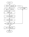
- FIG. 11 is a flowchart showing a method for manufacturing a three-dimensional structure according to the first embodiment of the present invention.
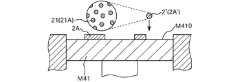
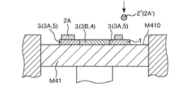
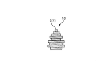
- the manufacturing method of the three-dimensional structure 10 of this embodiment is a method of manufacturing the three-dimensional structure 10 by laminating a plurality of layers 1, and includes a plurality of particles 21.
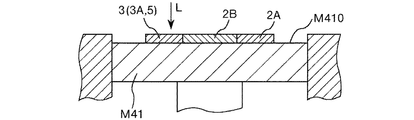
- (Composition) Layer formation step (see FIGS. 1, 2, 5, and 6) for forming the layer 1 using 2 ′, and particles contained in the layer 1 by irradiating the layer 1 with the laser beam L
- a series of steps including a joining step (see FIGS. 3, 4, 7, and 8) for joining 21 to each other is repeated (see FIG. 9).
- the arithmetic average height Sa (ISO 25178) of the surface of the layer 1 in a state where the particles 21 are bonded to each other by the bonding step is 15 ⁇ m or less.
- particles 21 or a melt thereof (hereinafter also simply referred to as “particles 21 or the like”) is scattered or voids (holes or voids) are formed inside the three-dimensional structure 10. It is possible to effectively prevent a reduction in the dimensional accuracy of the three-dimensional structure 10 or a decrease in the strength of the three-dimensional structure 10, and to manufacture the three-dimensional structure 10 having excellent reliability.
- the manufacturing method of the three-dimensional structure 10 which can be provided can be provided.
- the energy causes the particles to be ejected from the initial position of the layer or a liquid pool of the particles ( As the molten pool) undulates and the laser beam is scanned, the melt may be ejected, causing unintended irregularities on the surface of the layer after laser beam irradiation, and finally obtaining the tertiary
- the dimensional accuracy of the original model was lowered.
- the average particle diameter D 50 of the particles and the thickness D S of the layer formed in the layer forming step satisfy a predetermined relationship (D S / D 50 ⁇ 5.0).
- the conditions regarding the arithmetic average height Sa of the surface of the layer formed by the above joining processes should just be satisfied at least in the region corresponding to the substantial part of the three-dimensional structure to be manufactured.
- the region corresponding to the support portion 5 may not satisfy the condition for the arithmetic average height Sa as described above. It is preferable that both the area corresponding to the entity part 4 and the area corresponding to the support part 5 satisfy the condition regarding the arithmetic average height Sa as described above. Thereby, the effects as described above are more remarkably exhibited.
- the average particle diameter means a volume-based average particle diameter.
- a dispersion obtained by adding a sample to methanol and dispersing for 3 minutes with an ultrasonic disperser is used as a Coulter counter particle size distribution analyzer (COULTER ELECTRONICS). It can be determined by measuring with a 50 ⁇ m aperture using an INS TA-II type).
- the ratio of the layer thickness D S to the average particle diameter D 50 of the particles (D S / D 50 ) is too large, scattering of particles or the like when irradiated with laser light, or the inside of the three-dimensional structure Air gaps (holes, voids) are likely to occur.
- the value of D S / D 50 by D S is a large value is large, in the thickness direction (height direction), it is difficult to produce a precise three-dimensional shaped object than the thickness of the layer, As a result, the dimensional accuracy of the three-dimensional structure decreases.
- D S / D 50 by D 50 is smaller is high, scattering and particle like when irradiated with laser light as described above, voids in the interior of the three-dimensional model ( The generation of vacancies and voids becomes more prominent.
- liquidity of the composition for three-dimensional structure manufacture falls, the ease of handling of the composition for three-dimensional structure manufacture falls, and the productivity of a three-dimensional structure falls.
- the value of D 50 is particularly small, tends to occur agglomeration of the particles in the 3D object for producing a composition, in a stage before the laser irradiation, it tends to occur undesirable unevenness of the surface of the layer Become.
- the dimensional accuracy of the three-dimensional structure is particularly low, coupled with the influence of scattering of particles and the like when irradiated with laser light.
- the arithmetic average height Sa of the surface of the layer in a state where the particles are bonded by the bonding process is too large, the unevenness existing on the surface of the layer has a large effect on the shape of the layer formed on the upper surface of the layer. The dimensional accuracy of the finally obtained three-dimensional structure decreases.
- D S / D 50 ⁇ 5.0 when the average particle diameter of the particles 21 is D 50 [ ⁇ m] and the thickness of the layer 1 formed in the layer forming step is D S [ ⁇ m], D S / D 50 ⁇ 5.0.
- the relationship may be satisfied, but it is preferable that the relationship of 1.0 ⁇ D S / D 50 ⁇ 4.0 is satisfied, and the relationship of 1.2 ⁇ D S / D 50 ⁇ 3.5 is satisfied. More preferably, it is more preferable that the relationship of 1.4 ⁇ D S / D 50 ⁇ 3.0 is satisfied. Thereby, the effects as described above are more remarkably exhibited.
- the arithmetic average height Sa of the surface of the layer 1 in a state where the particles 21 are bonded to each other by the bonding process may be 15 ⁇ m or less, preferably 11 ⁇ m or less, and preferably 8.0 ⁇ m or less. More preferably, it is more than 0 ⁇ m and 5.0 ⁇ m or less. Thereby, the effects as described above are more remarkably exhibited.
- the configuration of the composition 2 ′ for manufacturing a three-dimensional structure more specifically, For example, the constituent material of the particles 21, the particle size, the particle size distribution, etc., the thickness of the layer 1 formed in the layer forming step, the irradiation conditions of the laser light L (for example, the type of the laser light L, the beam diameter of the laser light L) Scanning speed, laser output, etc.).
- composition 2 'for three-dimensional structure manufacture what contains the solvent which functions as a dispersion medium which disperse
- a solvent removal process is provided between the layer formation process and the bonding process.
- liquidity of composition 2 'for three-dimensional structure manufacture is made favorable, and the ease of handling of composition 2' for three-dimensional structure manufacture and the ease of formation of layer 1 are improved. Can do. Further, the flatness of the formed layer 1 can be made better.
- a solvent is a liquid (dispersion medium) which can disperse
- the layer 1 is formed by discharging the composition 2 ′ for manufacturing a three-dimensional structure.
- the layer 1 is formed by a discharge method.
- 3D modeling composition 2 ' can be provided with the pattern corresponding to the cross-sectional shape etc. of the three-dimensional modeling thing 10 which should be manufactured, and the three-dimensional modeling object 10 which has a finer structure also. It can manufacture suitably. Moreover, according to the cross-sectional area of the three-dimensional structure 10 to be manufactured, the application amount of the composition 2 ′ for manufacturing a three-dimensional structure in each layer 1 can be suitably adjusted, and the composition 2 for manufacturing a three-dimensional structure 2 The amount of use can be suppressed.
- waste of the composition 2 ′ for manufacturing the three-dimensional structure can be suppressed, and the recovery of the composition 2 ′ for manufacturing the three-dimensional structure 2 ′ that has not been used for manufacturing the three-dimensional structure 10 can be performed. It can be omitted or simplified.
- Such an effect is obtained when the cross-sectional area of the three-dimensional structure 10 to be manufactured is particularly small compared to the area of the stage M41 (for example, the cross-sectional area of the three-dimensional structure 10 to be manufactured is equal to the area of the stage M41). In the case of 1/10 or less, etc.).
- the discharge method refers to a method of forming a pattern corresponding to a layer by discharging a composition (a composition for producing a three-dimensional structure) in a predetermined pattern, and a supplied composition. It is distinguished from a method of forming a layer by flattening an object with a squeegee, a roller or the like (method of a second embodiment described later).
- composition 2B ' (particulate formation composition 2B' (particle
- composition 2A ′ composition containing composition (particle (dispersoid) used for forming the support portion (support portion, support material) 5 that supports the portion to be the substantial portion 4)
- composition containing 21A A composition containing 21A).
- a first pattern forming step (support portion pattern forming step) in which a support portion forming composition (composition) 2A ′ is discharged to form a first pattern (support portion pattern) 2A;
- a second pattern forming step (substantive portion pattern forming step) for discharging the forming composition (composition) 2B ′ to form a second pattern (substance portion pattern) 2B.
- the dimensional accuracy of the three-dimensional structure 10 can be further improved.
- even the three-dimensional structure 10 having a more complicated shape can be suitably manufactured.
- the layer 1 in which at least one of the composition 2B ′ for forming the substantial part as the composition 2 ′ for manufacturing the three-dimensional structure 2A ′ and the composition 2A ′ for supporting part formation is formed in the layer forming step.
- the above-described conditions (the relationship of D S / D 50 ⁇ 5.0) are satisfied. Thereby, the reliability of the three-dimensional structure 10 can be further improved.
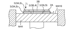
- First pattern formation process the support portion forming composition 2A ′ is discharged onto, for example, the plane M410 of the stage M41 to form the first pattern 2A.
- the first pattern 2A by discharging the support portion forming composition 2A ', even a pattern having a fine shape or a complicated shape can be suitably formed.
- the method for discharging the support portion forming composition 2A ' is not particularly limited, and for example, it may be performed using an ink jet apparatus or the like, but is preferably discharged by a dispenser.
- the support portion forming composition 2A ′ may be in a paste form, for example.
- the viscosity of the support portion forming composition 2A ′ in this step is preferably from 100 mPa ⁇ s to 1,000,000 mPa ⁇ s, more preferably from 500 mPa ⁇ s to 100,000 mPa ⁇ s, and more preferably from 1000 mPa ⁇ s to 20,000 mPa ⁇ s. More preferably, it is s or less.
- the discharge stability of the support portion forming composition 2A ′ can be further improved, and it is suitable for forming the layer 1 having an appropriate thickness, and the productivity of the three-dimensional structure 10 is improved. It can be improved further.
- the support portion forming composition 2A ′ in contact with the adherend is more effectively prevented from spreading excessively, and the dimensional accuracy of the finally obtained three-dimensional structure 10 can be further improved. .
- the viscosity means a value measured using a rheometer under the condition of shear rate: 10 [s ⁇ 1 ] unless otherwise specified.
- the support portion forming composition 2A ′ may be discharged in a continuous form or as a plurality of droplets, but is preferably discharged as a plurality of droplets.
- the volume per droplet of the discharged droplets is preferably 1 pL or more and 100000 pL (100 nL) or less, and preferably 10 pL or more and 50000 pL. (50 nL) or less is more preferable.
- the dimensional accuracy of the three-dimensional structure 10 can be further improved, and the three-dimensional structure 10 The productivity can be further improved.
- compositions may be used as the support portion forming composition 2 ⁇ / b> A ′.
- the support portion forming composition 2A ′ will be described in detail later.
- Second pattern formation process In the second pattern forming step, the entity pattern forming composition 2B ′ is discharged to form the second pattern 2B.
- the second pattern 2B by discharging the substance forming composition 2B ', even a pattern having a fine shape or a complicated shape can be suitably formed.
- the composition for forming a substantial part 2B ′ is ejected to a region surrounded by the first pattern 2A so that the entire periphery of the second pattern 2B is in contact with the first pattern 2A. To do.
- the method for discharging the substance forming composition 2B ' is not particularly limited, and for example, it can be performed using an ink jet apparatus or the like, but is preferably discharged by a dispenser.
- the entity forming composition 2B ′ may be in the form of a paste, for example.
- the viscosity of the entity forming composition 2B ′ in this step is preferably from 100 mPa ⁇ s to 1000000 mPa ⁇ s, more preferably from 500 mPa ⁇ s to 100000 mPa ⁇ s, more preferably from 1000 mPa ⁇ s to 20000 mPa ⁇ s. More preferably, it is s or less.
- the substance forming composition 2B ′ may be ejected in a continuous form or a plurality of droplets, but is preferably ejected as a plurality of droplets.
- the volume per droplet of the ejected droplets is preferably 1 pL or more and 100000 pL (100 nL) or less, preferably 10 pL or more and 50000 pL. (50 nL) or less is more preferable.
- the dimensional accuracy of the three-dimensional structure 10 can be further improved, and the three-dimensional structure 10 The productivity can be further improved.
- composition 2B ' In the production of the three-dimensional structure 10, a plurality of types of compositions may be used as the entity forming composition 2B '.
- materials can be combined according to characteristics required for each part of the three-dimensional structure 10, and characteristics (appearance, functionality (for example, elasticity, toughness, heat resistance) of the three-dimensional structure 10 as a whole. And the like) and the like can be further improved.
- the layer forming process includes a first pattern forming process and a second pattern forming process.
- the thickness D S of the layer 1 formed by a layer forming step is not particularly limited, but is preferably 5 ⁇ m or 300 ⁇ m or less, more preferably at 10 ⁇ m or 200 ⁇ m or less, at 20 ⁇ m or 100 ⁇ m or less Further preferred.
- the reliability (particularly, dimensional accuracy, strength, etc.) of the three-dimensional structure 10 can be further improved.
- the fluidity of the layer 1 is lowered and the stability of the shape of the layer 1 is improved.
- this step it is possible to effectively prevent unintentional deformation caused by rapid volatilization (such as bumping) of the solvent in the subsequent bonding step. From the above, it is possible to obtain the three-dimensional structure 10 having more reliable reliability (for example, dimensional accuracy, strength, etc.) and improve the productivity of the three-dimensional structure 10 more reliably. it can.
- a gas having a low content of liquid components such as dry air (for example, A gas having a relative humidity of 30% or less).
- a gas having a relative humidity of 30% or less for example, you may carry out combining 2 or more types selected from these.
- a solvent removal step (first solvent removal step) is performed on the first pattern 2A completed in the first pattern formation step, and then the second pattern 2B completed in the second pattern formation step
- a solvent removing step (second solvent removing step) may be performed.
- the content of the solvent in the layer 1 after this step is preferably 0.1% by mass or more and 25% by mass or less, and more preferably 0.5% by mass or more and 20% by mass or less.
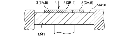
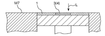
- the layer 1 is irradiated (scanned) with the laser beam L (see FIGS. 3, 4, 7, and 8).
- the particles 21 included in the composition 2 ′ for manufacturing a three-dimensional structure are bonded to each other, and the bonded portion 3 is formed.
- the joint portion 3 By forming the joint portion 3 in this way, the subsequent unintentional movement of the particles 21 is prevented, and the dimensional accuracy and strength of the three-dimensional structure 10 can be improved.
- the particles 21 are generally joined with sufficient joint strength.
- the layer 1 having the bonding portion 3 formed on the lower side of the layer 1 irradiated with the laser beam L generally, the bonding portion 3 of the lower layer 1; The newly formed joint 3 is joined. For this reason, the mechanical strength of the finally obtained three-dimensional structure 10 can be improved.
- the laser beam L energy can be imparted to a desired part with high selectivity, which is advantageous in improving the dimensional accuracy of the three-dimensional structure 10 and the three-dimensional structure 10. This is also advantageous in improving the productivity. Moreover, energy efficiency can be improved and it is advantageous also from an energy-saving viewpoint.
- the particles 21 are joined by irradiation with the laser beam L, and unnecessary components other than the particles 21 can be removed.
- unnecessary components other than the particles 21 can be removed.
- a binder, a solvent, etc. can be removed and it can prevent effectively that these components remain in the junction part 3 formed.
- the joining step is performed so that the arithmetic average height Sa of the surface of the layer 1 in a state where the particles 21 are joined by this step (joining step) is 15 ⁇ m or less, the joining portion 3 is formed.
- the flatness of the surface of the formed layer 1 can be made excellent.
- irradiation is performed by using the composition 2 ′ for manufacturing a three-dimensional structure that satisfies the above-described conditions (the relationship of D S / D 50 ⁇ 5.0) with the layer 1 formed in the layer forming step. Unintentional scattering of the particles 21 and the like due to the energy of the laser light L is effectively prevented. Therefore, the three-dimensional structure 10 having excellent reliability (dimensional accuracy, strength, etc.) can be obtained.
- the form of joining varies depending on the constituent material of the particles 21, and examples thereof include fusion, sintering, and melt solidification.
- a joining process irradiates laser beam L with respect to 1st pattern 2A formed using composition 2A 'for support part formation, and joins particle
- the first bonding step for forming 3A and the second pattern 2B formed using the composition for forming a substantial part 2B ′ are irradiated with laser light L to bond the particles 21B together.
- the joint portion (second joint portion) 3B is formed in the portion that becomes the substantial portion 4 of the three-dimensional structure 10 and functions as the support portion 5 in the manufacturing process of the three-dimensional structure 10.
- a joining portion (first joining portion) 3A to be formed is formed.
- the stability of the shape of the supporting portion 5 to be supported can be further improved, the occurrence of unintentional deformation in the manufacturing process of the three-dimensional structure 10 can be more effectively prevented, and finally obtained tertiary
- the dimensional accuracy of the original shaped article 10 can be further improved.
- lasers examples include solid lasers such as ruby lasers, YAG lasers, Nd: YAG lasers, titanium sapphire lasers, and semiconductor lasers; liquid lasers such as dye lasers; neutral atom lasers (helium neon lasers) Gas lasers such as ion laser (argon ion laser, etc.), molecular laser (carbon dioxide laser, nitrogen laser, etc.), excimer laser, metal vapor laser (helium cadmium laser, etc.); free electron laser; oxygen-iodine chemical laser And chemical lasers such as hydrogen fluoride laser; fiber lasers and the like.
- solid lasers such as ruby lasers, YAG lasers, Nd: YAG lasers, titanium sapphire lasers, and semiconductor lasers
- liquid lasers such as dye lasers
- neutral atom lasers helium neon lasers
- Gas lasers such as ion laser (argon ion laser, etc.), molecular laser (carbon dioxide laser, nitrogen laser, etc.), excimer laser, metal
- the thickness of the layer 1 having the joint portion 3 is not particularly limited, but is preferably 5 ⁇ m or more and 300 ⁇ m or less, more preferably 10 ⁇ m or more and 200 ⁇ m or less, and further preferably 20 ⁇ m or more and 100 ⁇ m or less.
- the reliability (dimensional accuracy, strength, etc.) of the three-dimensional structure 10 can be further improved while improving the productivity of the three-dimensional structure 10.
- the irradiation conditions of the laser beam L may be adjusted to be different in each part of the layer 1.
- the irradiation condition of the laser beam L so that the bonding strength of the particles 21A in the bonding portion 3A (support material 5) is smaller than the bonding strength of the particles 21B in the bonding portion 3B (substance portion 4). (Irradiation energy etc.) may be adjusted.
- productivity of the three-dimensional structure 10 can be improved more, and the three-dimensional structure 10 in the support material removal process can be improved.
- the occurrence of defects can be prevented more effectively, and the reliability (such as dimensional accuracy) of the finally obtained three-dimensional structure 10 can be further improved.
- the surface of the layer 1 in a state where the particles 21 are bonded to each other by the bonding process (the surface of the layer 1 after the bonding process) satisfies the conditions for the arithmetic average height Sa (ISO 25178) as described above. What is necessary is just to satisfy, but it is preferable to satisfy the following conditions further.
- the maximum height Sz (ISO 25178) of the surface of the layer 1 in a state where the particles 21 are bonded by the bonding process is preferably 250 ⁇ m or less, more preferably 200 ⁇ m or less, and more than 0 ⁇ m and 150 ⁇ m or less. More preferably.
- the root mean square height Sq (ISO 25178) of the surface of the layer 1 in a state where the particles 21 are bonded by the bonding process is preferably 30 ⁇ m or less, more preferably 20 ⁇ m or less, and more than 0 ⁇ m. More preferably, it is 15 ⁇ m or less.
- the skewness deviation degree Ssk (ISO 25178) of the surface of the layer 1 in a state where the particles 21 are bonded by the bonding process is preferably ⁇ 1.0 or more and 2.0 or less, and ⁇ 0.5 or more and 1 It is more preferably 0.5 or less, and further preferably ⁇ 0.3 or more and 1.0 or less.
- the kurtosis kurtosis Sku (ISO 25178) of the surface of the layer 1 in a state where the particles 21 are bonded to each other by the bonding step is preferably 15 or less, more preferably 10 or less, and more than 0. More preferably, it is 0 or less.
- the maximum peak height Sp (ISO 25178) of the surface of the layer 1 in a state where the particles 21 are bonded by the bonding process is preferably 200 ⁇ m or less, more preferably 150 ⁇ m or less, and more than 0 ⁇ m and 70 ⁇ m or less. More preferably.
- the maximum valley depth Sv (ISO 25178) of the surface of the layer 1 in a state where the particles 21 are bonded by the bonding process is preferably 150 ⁇ m or less, more preferably 100 ⁇ m or less, and more than 0 ⁇ m and 50 ⁇ m. More preferably, it is as follows.
- the conditions (maximum height Sz, skewness bias degree Ssk, kurtosis sharpness Sku, maximum peak height Sp, maximum valley depth Sv) about the surface of the layer 1 after the joining process as described above are the three-dimensional structures to be manufactured. It is preferable that the area corresponding to the entity part 4 is satisfied, but it is more preferable that both the area corresponding to the entity part 4 and the area corresponding to the support part 5 are satisfied. Thereby, the effects as described above are more remarkably exhibited.
- ⁇ Support part removal process In the present embodiment, after a series of steps including a layer forming step (first pattern forming step and second pattern forming step), a solvent removing step and a bonding step are repeatedly performed (see FIG. 9), as a post-processing step Then, the support material 5 is removed (see FIG. 10). Thereby, the three-dimensional structure 10 is taken out.
- Specific examples of the process include a method of dissolving at least a part of the support material 5 and a method of breaking the support material 5 by breaking it.
- a series of steps including a layer formation step (first pattern formation step and second pattern formation step), a solvent removal step and a bonding step are repeated a predetermined number of times, and a plurality of layers A laminate in which 1 is laminated is obtained.
- a support part removing step as post-processing is performed on the laminated body to obtain a target three-dimensional structure 10.
- the above-described series of steps is performed once to form one layer 1.
- the above-described series of steps may be repeated to form one layer.
- the layer forming step (first pattern forming step) or the bonding step for the support portion forming composition 2A ′ the layer forming step (second pattern forming step) for the substantial portion forming composition 2B ′.
- one layer may be formed by performing a bonding process.
- the particles 21 and the like are scattered in the manufacturing process of the three-dimensional structure 10 and that voids (holes and voids) are formed inside the three-dimensional structure 10.
- the three-dimensional structure 10 having excellent reliability (dimensional accuracy, strength, etc.) can be efficiently manufactured.
- composition for three-dimensional structure production Next, the composition for manufacturing a three-dimensional structure used in the manufacturing method of the embodiment described above will be described.
- the layer 1 in which at least one type of three-dimensional structure manufacturing composition 2 ′ is formed in the layer forming step is formed in the layer forming step.
- the above-described conditions the relationship of D S / D 50 ⁇ 5.0
- the substantial part forming composition 2B ′ and the support part forming composition 2A ′ satisfy the above-mentioned conditions (the relationship of D S / D 50 ⁇ 5.0) with the layer 1 formed in the layer forming step. More preferably.
- the three-dimensional structure 10 having excellent reliability can be manufactured.
- composition for producing a three-dimensional structure a composition 2B 'for forming an entity part and a composition 2A' for forming a support part are used.
- composition 2B ′ As a three-dimensional structure manufacturing composition used for manufacturing the three-dimensional structure 10 will be described.
- the constituent part forming composition 2B ′ is not particularly limited as long as it can be used to form the substantial part 4 (formation of the second pattern 2B), but a plurality of particles 21B (main material particles) are not particularly limited. And the above-described conditions (the relationship of D S / D 50 ⁇ 5.0) with the layer 1 formed in the layer forming step are preferably satisfied.
- composition for forming an entity part 2B ′ includes the plurality of particles 21B and the above-described conditions (D S / D 50 ⁇ 5. 5) with the layer 1 formed in the layer forming step. A case where the relationship of 0) is satisfied will be described representatively.
- the range of selection of the constituent material of the three-dimensional structure 10 can be expanded, and the three-dimensional structure having desired physical properties, textures, and the like. 10 can be suitably obtained.
- the material that can be used there are limitations on the material that can be used, but by using the composition for forming an entity part 2B ′ including the particles 21B, Limits can be removed.
- Examples of the constituent material of the particles 21 ⁇ / b> B included in the substance forming composition 2 ⁇ / b> B ′ include metal materials, metal compounds (ceramics, etc.), resin materials, pigments, and the like.
- composition 2B ' preferably includes metal particles made of a material including a metal material.
- the texture (luxury feeling, weight feeling), mechanical strength, toughness, durability and the like of the three-dimensional structure 10 can be further improved.
- heat transfer at the time of applying energy for joining the particles 21B proceeds efficiently, unintentional variations in temperature at each part are generated while improving the productivity of the three-dimensional structure 10. It can prevent more effectively and can improve the reliability of the three-dimensional structure 10 more.
- Examples of the metal material constituting the particles 21B include magnesium, iron, copper, cobalt, titanium, chromium, nickel, aluminum and alloys containing at least one of these (for example, maraging steel, stainless steel, cobalt chromium molybdenum). , Titanium alloys, nickel-based alloys, aluminum alloys, etc.).
- Examples of the metal compound constituting the particle 21B include various metal oxides such as silica, alumina, titanium oxide, zinc oxide, zircon oxide, tin oxide, magnesium oxide, and potassium titanate; magnesium hydroxide, aluminum hydroxide, water Various metal hydroxides such as calcium oxide; various metal nitrides such as silicon nitride, titanium nitride and aluminum nitride; various metal carbides such as silicon carbide and titanium carbide; various metal sulfides such as zinc sulfide; calcium carbonate and magnesium carbonate Carbonate of various metals such as calcium sulfate, sulfate of various metals such as magnesium sulfate, silicate of various metals such as calcium silicate and magnesium silicate, phosphate of various metals such as calcium phosphate, aluminum borate , Borate salts of various metals such as magnesium borate, and composites of these It is.
- various metal oxides such as silica, alumina, titanium oxide, zinc oxide, zircon
- Examples of the resin material constituting the particles 21B include polybutylene terephthalate, polyethylene terephthalate, polypropylene, polystyrene, syndiotactic polystyrene, polyacetal, modified polyphenylene ether, polyether ether ketone, polycarbonate, acrylonitrile-butadiene-styrene copolymer. (ABS resin), polyether nitrile, polyamide (nylon, etc.), polyarylate, polyamide imide, polyether imide, polyimide, liquid crystal polymer, polysulfone, polyether sulfone, polyphenylene sulfide, fluorine resin and the like.
- ABS resin polybutylene terephthalate
- polyethylene terephthalate polypropylene
- polystyrene syndiotactic polystyrene
- polyacetal modified polyphenylene ether
- polyether ether ketone polycarbonate
- the shape of the particle 21B is not particularly limited, and may be any shape such as a spherical shape, a spindle shape, a needle shape, a cylindrical shape, a scale shape, or an indefinite shape, but it is spherical. preferable.
- the average particle diameter of the particles 21B is not particularly limited, but is preferably 0.1 ⁇ m or more and less than 50 ⁇ m, more preferably 0.2 ⁇ m or more and 20 ⁇ m or less, and further preferably 0.3 ⁇ m or more and 10 ⁇ m or less. .
- the fluidity of the entity forming composition 2B ′ decreases, and the ease of handling of the entity forming composition 2B ′ decreases.
- the productivity of the three-dimensional structure 10 decreases. Further, scattering of particles and the like when irradiated with the laser beam L is likely to occur, and the dimensional accuracy of the three-dimensional structure 10 is likely to be reduced, or voids (holes, voids) are formed inside the three-dimensional structure 10. It tends to occur.
- the particles 21B tend to aggregate in the substance forming composition 2B ′, and the surface of the layer 1 is unintentionally in the stage before the irradiation with the laser beam L. Unevenness is likely to occur. As a result, the dimensional accuracy of the three-dimensional structure 10 tends to decrease particularly in combination with the influence of scattering of particles and the like when the laser beam L is irradiated.
- the dimensional accuracy of the three-dimensional structure 10 decreases due to the effect of easily forming irregularities on the surface of the layer 1 due to the size of the particles 21B itself. It becomes easy to do. In addition, it becomes difficult to sufficiently melt the particles 21 ⁇ / b> B, and voids (holes, voids) are easily generated inside the three-dimensional structure 10.
- the volume-based average particle diameter of the particles 21B is preferably 0.1 ⁇ m or more and 10 ⁇ m or less. It is more preferably 2 ⁇ m or more and 7.0 ⁇ m or less, and further preferably 0.3 ⁇ m or more and 4.0 ⁇ m or less.
- the reliability (dimensional accuracy, strength, etc.) of the manufactured three-dimensional structure 10 can be further improved while further improving the productivity of the three-dimensional structure 10.
- the Dmax of the particle 21B is preferably 0.2 ⁇ m or more and 80 ⁇ m or less, more preferably 0.4 ⁇ m or more and 40 ⁇ m or less, and further preferably 0.5 ⁇ m or more and 20 ⁇ m or less.
- the fluidity of the composition 2B ′ for forming the substantial part becomes more suitable, the second pattern forming process can be performed more smoothly, and the bonding of the particles 21B in the bonding process is more preferably performed. Can do.
- the strength of the manufactured three-dimensional structure 10 can be further improved, and the occurrence of unintentional irregularities in the manufactured three-dimensional structure 10. Etc. can be more effectively prevented, and the dimensional accuracy of the three-dimensional structure 10 can be further improved.
- the content ratio of the particles 21B in the substantial part forming composition 2B ′ is preferably 30% by mass to 95% by mass, and more preferably 35% by mass to 92% by mass.
- the particles 21B are made of a material that undergoes a chemical reaction (for example, an oxidation reaction) in the manufacturing process (for example, a bonding step) of the three-dimensional structure 10 and is contained in the substance forming composition 2B ′.
- the composition of the particles 21 ⁇ / b> B included in the structure and the constituent material of the final three-dimensional structure 10 may be different.
- the entity forming composition 2B ′ may contain two or more kinds of particles 21B.
- the particles 21B can be suitably dispersed in the entity forming composition 2B ′, and the entity forming composition 2B using a dispenser or the like can be used. 'Can be discharged stably.
- the solvent is not particularly limited as long as it has a function of dispersing the particles 21B (function as a dispersion medium) in the composition for forming an entity part 2B ′.
- a dispersion medium for example, water; ethylene glycol monomethyl ether, ethylene glycol mono Ethers such as ethyl ether, propylene glycol monomethyl ether, propylene glycol monoethyl ether, diethyl diglycol, diethylene glycol monobutyl ether acetate; ethyl acetate, n-propyl acetate, iso-propyl acetate, n-butyl acetate, iso-butyl acetate, etc.
- Acetates such as carbitols such as carbitol and its ester compounds (for example, carbitol acetate); cellosolobs such as cellosorb and its ester compounds (for example, cellosorob acetate); benzene Aromatic hydrocarbons such as toluene and xylene; ketones such as methyl ethyl ketone, acetone, methyl isobutyl ketone, ethyl-n-butyl ketone, diisopropyl ketone, and acetylacetone; monohydric alcohols such as ethanol, propanol, and butanol, ethylene glycol, propylene Alcohols such as polyhydric alcohols such as glycol, butanediol and glycerin; sulfoxide solvents such as dimethyl sulfoxide and diethyl sulfoxide; pyridine, picoline ( ⁇ -picoline, ⁇ -picoline, ⁇
- Pyridine-based solvents such as tetraalkylammonium acetate (for example, tetrabutylammonium acetate, etc.), and the like can be used alone or in combination of two or more.
- Rukoto can be used alone or in combination of two or more.
- the content of the solvent in the substantial part forming composition 2B ′ is preferably 5% by mass or more and 70% by mass or less, and more preferably 8% by mass or more and 65% by mass or less.
- the productivity of the three-dimensional structure 10 can be further improved while further improving the ease of handling the composition 2B ′ for forming the substantial part, and from the viewpoint of production cost, resource saving, and the like. Is also particularly advantageous. Moreover, the dimensional accuracy of the finally obtained three-dimensional structure 10 can be further improved.
- the entity forming composition 2B ′ may include a binder having a function of temporarily bonding the particles 21B to each other in a state where the solvent is removed.
- the binder for forming the substantial part 2B ′ for example, it is possible to more effectively prevent unintentional deformation of the second pattern 2B formed using the composition 2B ′ for forming the substantial part. it can. Moreover, the unintentional scattering of the particles 21B and the melt thereof when the laser beam L is irradiated in the joining step can be more effectively prevented. Thereby, generation
- the binder only needs to have a function of temporarily fixing the particles 21B in the composition 2B ′ (second pattern 2B) for forming the substantial part before being subjected to the joining step.
- a thermoplastic resin Various resin materials such as a curable resin can be used.
- the curing reaction of the curable resin may be performed at a timing after the ejection of the entity forming composition 2 ⁇ / b> B ′ and before the joining step.
- the curing treatment for causing the curing reaction of the curable resin to proceed can be performed by, for example, heating or irradiation with energy rays such as ultraviolet rays.
- thermosetting resins and photocurable resins can be suitably used.
- binder examples include acrylic resin, epoxy resin, silicone resin, polyvinyl alcohol, PLA (polylactic acid), PA (polyamide), PPS (polyphenylene sulfide), and the like.
- the binder may be contained in any form, but the entity part forming composition 2B ′ is in a liquid state (for example, a molten state, a dissolved state, etc.) as a binder.
- a liquid state for example, a molten state, a dissolved state, etc.
- it contains the components. That is, it is preferable that at least a part of the binder is contained as a constituent component of the dispersion medium.
- the binder can function as a dispersion medium for dispersing the particles 21 ⁇ / b> B, and can further improve the storage stability of the entity forming composition 2 ⁇ / b> B ′.
- composition 2B ' may contain nanocellulose as a binder.
- Nanocellulose is a fibrous substance composed of cellulose or a cellulose derivative and having a width and thickness of 100 nm or less, and is a concept including so-called cellulose nanofibers and cellulose nanocrystals.
- the viscosity of the whole entity forming composition 2B ' can be adjusted to a suitable range with a relatively low content.
- the viscosity of the substantial part forming composition 2B ′ is sufficiently high without increasing the content ratio of the particles 21B and the content ratio of the binder other than nanocellulose in the substantial part forming composition 2B ′. can do. Therefore, it is possible to effectively prevent the unintentional aggregation of the particles 21B in the entity forming composition 2B ′ and the unintentional composition variation in the entity forming composition 2B ′ or the three-dimensional structure 10. However, unintentional deformation of the layer 1 can be prevented.
- the entity forming composition 2B ′ containing nanocellulose has thixotropy, and in a state where shear stress is applied as in ejection, the viscosity of the entity forming composition 2B ′ decreases and is stable. Discharge can be performed. Moreover, since the amount of the binder contained in the composition 2B ′ for forming the substantial part can be reduced, the binder and its decomposition product remain unintentionally in the finally obtained three-dimensional structure 10. This can be prevented more effectively. Moreover, from the above, the reliability of the three-dimensional structure 10 can be further improved.
- the binder content in the entity forming composition 2B ′ exceeds the upper limit, the proportion of the particles 21B in the solid content of the entity forming composition 2B ′ tends to be relatively low.
- the volume reduction rate due to bumping at the time of laser irradiation in the manufacturing process of the three-dimensional structure 10 increases, and the dimensional accuracy of the finally obtained three-dimensional structure 10 tends to decrease.
- the content of impurities (for example, carbon) derived from the binder may be high.
- composition 2B ′ may contain components other than those described above.
- examples of such components include a polymerization initiator; a dispersant; a surfactant; a thickener; an agglomeration inhibitor; an antifoaming agent; a slip agent (leveling agent); a dye; a polymerization inhibitor; Accelerators; humectants (humectants); fixing agents; antifungal agents; antiseptics; antioxidants; ultraviolet absorbers; chelating agents;
- the support portion forming composition 2A ′ can be used for forming the support portion 5 (formation of the first pattern 2A), its constituent components and the like are not particularly limited, but a plurality of particles 21A (main material particles). And the above-described conditions (the relationship of D S / D 50 ⁇ 5.0) with the layer 1 formed in the layer forming step are preferably satisfied.
- the support portion forming composition 2A ′ includes the plurality of particles 21A and the above-described conditions (D S / D 50 ⁇ 5. 5) with the layer 1 formed in the layer forming step. A case where the relationship of 0) is satisfied will be described representatively.
- the support part 5 to be formed (first pattern 2A) has a fine shape by including the plurality of particles 21A in the support part forming composition 2A ′, the support part 5 is formed. It can be formed efficiently with high dimensional accuracy. Moreover, a solvent and a binder (a decomposition product is included) can be efficiently removed from the clearance gap between the some particle
- the particles 21A constituting the support portion forming composition 2A ' are preferably made of a material having a higher melting point than the particles 21B constituting the substantial portion forming composition 2B'.
- the shape of the particle 21A is not particularly limited, and may be any shape such as a spherical shape, a spindle shape, a needle shape, a cylindrical shape, a scale shape, or an indefinite shape, but it is spherical. preferable.
- the average particle diameter of the particles 21A is not particularly limited, but is preferably 0.1 ⁇ m or more and less than 50 ⁇ m, more preferably 0.2 ⁇ m or more and 20 ⁇ m or less, and further preferably 0.3 ⁇ m or more and 10 ⁇ m or less. .
- the average particle size of the particles 21A is less than the lower limit, the fluidity of the support portion forming composition 2A ′ is lowered, and the supportability of the support portion forming composition 2A ′ is lowered.
- the productivity of the three-dimensional structure 10 decreases.
- scattering of particles and the like when irradiated with the laser beam L is likely to occur, and the dimensional accuracy of the three-dimensional structure 10 is likely to be lowered.
- the average particle diameter of the particles 21A is particularly small, the particles 21A are likely to aggregate in the support portion forming composition 2A ′, and the surface of the layer 1 is unintentionally in the stage before the irradiation with the laser beam L. Unevenness is likely to occur.
- the dimensional accuracy of the three-dimensional structure 10 tends to decrease particularly in combination with the influence of scattering of particles and the like when the laser beam L is irradiated.
- the dimensional accuracy of the three-dimensional structure 10 decreases due to the fact that the surface of the layer 1 is likely to be uneven due to the size of the particles 21A itself. It becomes easy to do.
- Dmax of the particle 21A is preferably 0.2 ⁇ m or more and 80 ⁇ m or less, more preferably 0.4 ⁇ m or more and 40 ⁇ m or less, and further preferably 0.5 ⁇ m or more and 20 ⁇ m or less.
- the solvent and binder (including decomposition products) can be more efficiently removed from the gaps between the plurality of particles 21 ⁇ / b> A constituting the support portion 5 (first pattern 2 ⁇ / b> A), and the three-dimensional structure 10 can be produced. The property can be further improved.
- the content ratio of the particles 21A in the support portion forming composition 2A ′ is preferably 30% by mass or more and 95% by mass or less, and more preferably 35% by mass or more and 92% by mass or less.
- the particles 21A are made of a material that undergoes a chemical reaction (for example, an oxidation reaction) in the manufacturing process (for example, a bonding step) of the three-dimensional structure 10, and in the support portion forming composition 2A ′.
- the composition of the particles 21 ⁇ / b> A included in the material and the constituent material of the final three-dimensional structure 10 may be different.
- the support portion forming composition 2A ′ may include two or more kinds of particles 21A.
- the support portion forming composition 2A ′ contains a solvent, whereby the particles can be suitably dispersed in the support portion forming composition 2A ′, and the discharge of the support portion forming composition 2A ′ by a dispenser or the like is stable. Can be done automatically.
- Examples of the solvent contained in the support portion forming composition 2A ′ include the same solvents as those described as the constituent material of the substantial portion forming composition 2B ′. Thereby, the same effect as described above can be obtained.
- composition of the solvent contained in the support portion forming composition 2A ′ may be the same as or different from the composition of the solvent contained in the entity portion forming composition 2B ′.
- the content of the solvent in the support portion forming composition 2A ′ is preferably 5% by mass or more and 70% by mass or less, and more preferably 8% by mass or more and 65% by mass or less.
- the support portion forming composition 2A ′ may include a binder having a function of temporarily bonding the particles 21A to each other in a state where the solvent is removed.
- the binder in the support portion forming composition 2A ′ for example, it is possible to more effectively prevent unintentional deformation of the first pattern 2A formed using the support portion forming composition 2A ′. it can. Moreover, the unintentional scattering of the particles 21A and the melt thereof when the laser beam L is irradiated in the joining step can be more effectively prevented. Thereby, generation
- binder examples include the same materials as those described as the constituent material of the entity forming composition 2B ′. Thereby, the same effect as described above can be obtained.
- the conditions such as the composition and content of the binder contained in the support portion forming composition 2A ′ are the same as those described for the binder contained in the entity portion forming composition 2B ′. preferable. Thereby, the same effect as described above can be obtained.
- the binder contained in the support part forming composition 2A ′ may satisfy the same conditions (for example, composition and content) as the binder contained in the substantial part forming composition 2B ′. However, different conditions may be used.
- the support portion forming composition 2A ′ may contain components other than those described above.
- such components include a polymerization initiator; a dispersant; a surfactant; a thickener; an agglomeration inhibitor; an antifoaming agent; a slip agent (leveling agent); a dye; a polymerization inhibitor; Accelerators; humectants (humectants); fixing agents; antifungal agents; antiseptics; antioxidants; ultraviolet absorbers; chelating agents;
- composition set for manufacturing 3D objects >> Next, the composition set for manufacturing a three-dimensional structure according to this embodiment will be described.
- the composition set for manufacturing a three-dimensional structure according to the present embodiment includes a plurality of types of compositions used for manufacturing the three-dimensional structure, and a plurality of particles 21 as at least one of the compositions. And a composition that satisfies the above-described conditions (the relationship of D S / D 50 ⁇ 5.0) with the layer 1 formed in the layer forming step.
- the composition set for manufacturing a three-dimensional structure may be provided with at least one composition for manufacturing a three-dimensional structure that satisfies the above-described conditions, but the three-dimensional structure that satisfies the above-described conditions. It is preferable to provide two or more kinds of production compositions. Thereby, the reliability of the three-dimensional structure 10 can be further improved.
- composition set for manufacturing a three-dimensional structure is used for forming an entity part used for forming the entity part 4 of the three-dimensional structure 10 as a composition 2 ′ for manufacturing a three-dimensional structure that satisfies the above-described conditions. It is preferable that at least one composition 2B ′ is provided and at least one support portion forming composition 2A ′ used for forming the support portion 5 is provided. Thereby, the reliability of the three-dimensional structure 10 can be further improved.
- Second Embodiment 12 to 19 are longitudinal sectional views schematically showing the steps of the three-dimensional structure manufacturing method according to the second embodiment of the present invention.
- FIG. 20 is a flowchart showing a method for manufacturing a three-dimensional structure according to the second embodiment of the present invention.
- the manufacturing method of the three-dimensional structure 10 of this embodiment is a method of manufacturing the three-dimensional structure 10 by laminating a plurality of layers 1, and includes a plurality of particles 21.
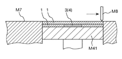
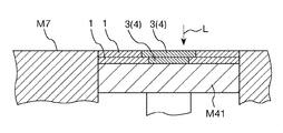
- (Composition) 2 ′ is planarized by a planarization means M8 to form a layer 1 (see FIGS. 12, 13, 15, and 16), and laser light L is applied to the layer 1 in a predetermined pattern. Irradiation and a series of steps including a joining step (see FIGS. 14 and 17) for partially joining the particles 21 included in the layer 1 are repeated (see FIG. 18).
- the composition 2 ′ for producing a three-dimensional structure is discharged to form the layer 1 (the layer 1 is formed by the discharging method), whereas in the present embodiment, the composition is once set.
- the three-dimensional structure manufacturing composition 2 ′ (see FIGS. 12 and 15) supplied on the object placement portion (composition temporary placement portion) M7 is flattened by the flattening means M8 (FIG. 13, FIG. 16), layer 1 is formed.
- the number of scanning processes for forming the layer 1 provided with the joint portion 3 can be reduced, and the productivity of the three-dimensional structure 10 can be further improved.
- the productivity of the three-dimensional structure 10 can be further improved.
- scanning at the time of application of the composition 2 ′ for manufacturing a three-dimensional structure (the composition 2A ′ for forming the support part, the composition 2B ′ for forming the substantial part), and the support
- the laser beam for joining the particles 21 is used. Only scanning at the time of irradiation of L can be done.
- the support part forming composition 2A ′ and the entity part forming composition 2B ′ are used as the three-dimensional structure manufacturing composition 2 ′.
- the composition 2 ′ for manufacturing a single type of three-dimensional structure is used, even a three-dimensional structure 10 having a complicated shape can be preferably manufactured.
- the composition 2 ′ (particle 21) for manufacturing a three-dimensional structure that was not used for forming the joint 3 is easily recovered, Can be reused. More specifically, the separation and purification treatment after the collection of the composition 2 ′ (particles 21) for producing a three-dimensional structure can be omitted or simplified.
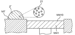
- the composition 2 ′ for manufacturing a three-dimensional structure is temporarily supplied (temporarily placed) on the composition placement portion (composition temporary placement portion) M7 (see FIGS. 12 and 15). Thereafter, the composition 2 ′ for producing a three-dimensional structure is flattened by the flattening means M8 (see FIGS. 13 and 16).
- the supply of the composition 2 ′ for producing a three-dimensional structure onto the composition placement portion (composition temporary placement portion) M ⁇ b> 7 can be performed by, for example, a hopper.
- the flattening means M8 is a squeegee, but the flattening means M8 may be anything as long as the layer 1 can be formed by flattening the composition 2 ′ for producing a three-dimensional structure.
- a roller etc. may be sufficient.
- the smooth layer 1 is formed by supplying the composition 2 ′ for manufacturing a three-dimensional structure to the entire region surrounded by the frame M ⁇ b> 45 on the stage (elevating stage) M ⁇ b> 41.
- the joining process was performed by irradiating (scanning) the laser beam L to the layer 1 as in the above-described embodiment.
- the solid part of the three-dimensional structure 10 is formed. 4 is selectively irradiated with the laser beam L.
- the junction part 3 is selectively formed in the site
- the frame M45 on the stage (elevating stage) M41 is surrounded by the present embodiment without forming the joint portion 3 in a portion other than the portion corresponding to the substantial portion 4 of the three-dimensional structure 10 as described above. Since the layer 1 is formed over the entire region, unintentional deformation of the layer 1 is prevented. Therefore, the dimensional accuracy of the three-dimensional structure 10 can be more reliably improved without forming the joint portion 3 in a part other than the part corresponding to the substance part 4 of the three-dimensional structure 10. Moreover, the composition 2 ′ (particles) for producing a three-dimensional structure that was not used for forming the joint 3 by not forming the joint 3 in a part other than the part corresponding to the substance part 4 of the three-dimensional structure 10. 21) can be easily recovered and reused. More specifically, the separation and purification treatment after the collection of the composition 2 ′ (particles 21) for producing a three-dimensional structure can be omitted or simplified.
- the same method as described in the support portion removal step of the above embodiment (a method of dissolving at least a part of the unnecessary portion, a method of breaking the unnecessary portion, etc.) Etc.) but is preferably recovered as a powder.
- the unnecessary part can be easily recovered and the recovered unnecessary part (particularly, the particles 21 included in the unnecessary part) can be suitably reused.
- a method for recovering the unnecessary part as powder for example, a method of removing the unnecessary part with a brush or the like, a method of removing the unnecessary part by suction, a method of blowing a gas such as air, a method of applying a liquid such as water, Examples include a method of applying vibration such as sonic vibration. Moreover, it can carry out combining 2 or more types of methods selected from these.
- a series of steps including a layer formation step, a solvent removal step, and a joining step are repeated a predetermined number of times to obtain a laminate in which a plurality of layers 1 are laminated.
- composition 2 ′ for manufacturing a three-dimensional structure used in the manufacturing method of the second embodiment will be described.
- the same composition as the substance forming composition 2B 'described in the first embodiment can be used as the composition 2' for manufacturing a three-dimensional structure. Thereby, the same effect as described above can be obtained.
- the composition 2 'for producing a three-dimensional structure is not required to have excellent ejection properties. Therefore, the composition 2 ′ for producing a three-dimensional structure can be suitably used for forming the layer 1 even if it does not contain a solvent.
- the content of the solvent in the composition 2 ′ for manufacturing a three-dimensional structure is 1% by mass or more and 70% by mass or less. Preferably, it is 2 mass% or more and 65 mass% or less.
- the composition 2 'for three-dimensional structure manufacture is supplied to the whole area
- the content of the binder in the composition 2 ′ for manufacturing a three-dimensional structure is 0.1 volume% or more and 7.5 volume% or less. It is preferable that it is 0.2 volume% or more and 7.0 volume% or less, and it is further more preferable that it is 0.3 volume% or more and 6.5 volume% or less.
- the content of the particles 21 in the three-dimensional structure manufacturing composition 2 ' is preferably 35% by mass or more and 100% by mass or less, and more preferably 40% by mass or more and 95% by mass or less.
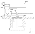
- FIG. 21 is a side view schematically showing the first embodiment of the three-dimensional structure manufacturing apparatus.
- the three-dimensional structure manufacturing apparatus M100 of this embodiment includes a nozzle that discharges a composition 2 ′ for manufacturing a three-dimensional structure, and a layer formed by discharging the composition 2 ′ for manufacturing a three-dimensional structure from the nozzle. 1 is provided with laser light irradiation means M6 for irradiating laser light L to 1, and the three-dimensional structure 10 is manufactured by stacking the layers 1.
- the three-dimensional structure manufacturing apparatus M100 of the present embodiment discharges a control part M2 and a composition (composition) 2 ′ for manufacturing a three-dimensional structure including the particles 21 in a predetermined pattern. And a laser beam irradiation means M6 for irradiating the composition 2 ′ supplied in a predetermined pattern with a laser beam L for joining the particles 21.
- the manufacturing method (particularly, the manufacturing method of the three-dimensional structure according to the first embodiment) of the present invention as described above can be suitably executed.
- the control unit M2 includes a computer M21 and a drive control unit M22.
- the computer M21 is a general desktop computer configured with a CPU, a memory, and the like inside.
- the computer M21 converts the shape of the three-dimensional structure 10 as model data, and outputs cross-sectional data (slice data) obtained by slicing the shape into parallel thin layers of slices to the drive control unit M22. .
- the drive control unit M22 included in the control unit M2 functions as a control unit that drives the composition supply unit (discharge unit) M3, the layer forming unit M4, the laser beam irradiation unit M6, and the like.
- driving of the composition supply means (discharge means) M3 (movement on the XY plane, etc.), discharge of the composition 2 ′ by the composition supply means (discharge means) M3, Z direction in FIG.
- the lowering of the movable stage (elevating stage) M41 and its lowering amount, the irradiation pattern and irradiation of the laser beam L by the laser beam irradiation means M6, the scanning speed, and the like are controlled.
- the material supply unit stores the composition 2 'described above, and is discharged from the composition supply unit (discharge unit) M3 under the control of the drive control unit M22.
- Composition supply means (discharge means) M3 can move independently in the X direction and Y direction in FIG. 12 along the guide M5.
- the layer forming unit M4 has a stage (elevating stage) M41 to which the composition 2 ′ is supplied and supports the layer 1 formed using the composition 2 ′, and a frame M45 surrounding the elevating stage M41. .
- the elevating stage M41 is sequentially lowered (moved in the negative Z-axis direction) by a predetermined amount according to a command from the drive control unit M22. To do.
- the stage M41 has a flat surface (liquid receiving surface) M410 on its upper surface (more specifically, a portion to which the composition 2 'is applied). Thereby, the layer 1 with high uniformity of thickness can be formed easily and reliably.
- the stage M41 is preferably made of a high-strength material.
- Examples of the constituent material of the stage M41 include various metal materials such as stainless steel.
- a surface treatment or a peeling structure may be applied to the plane M410 of the stage M41.
- the constituent material of the composition 2 ′ can be more effectively prevented from being firmly attached to the stage M41, the durability of the stage M41 can be improved, and the three-dimensional structure 10 can be made longer. Stable production over a period can be achieved.
- the composition supply means (discharge means) M3 is configured to move in accordance with a command from the drive control unit M22 and to discharge the composition 2 'to a desired site on the stage M41 in a predetermined pattern.
- the composition supply means (discharge means) M3 is configured to discharge the composition 2 ′.
- Examples of the composition supply unit (discharge unit) M3 include an ink jet head and various dispensers, and a dispenser is preferable.
- the highly viscous composition 2 ′ can be suitably supplied (discharged), and the sagging of the composition 2 ′ after the composition 2 ′ comes into contact with the target site is more effective. Can be prevented. As a result, the dimensional accuracy of the finally obtained three-dimensional structure 10 can be further improved. Further, by using the highly viscous composition 2 ′, the layer 1 having a relatively large thickness can be easily formed, and the productivity of the three-dimensional structure 10 can be further improved.
- the size (nozzle diameter) of the discharge portion of the composition supply means (discharge means) M3 is not particularly limited, but is preferably 10 ⁇ m or more and 100 ⁇ m or less.
- the productivity of the three-dimensional structure 10 can be further improved while further improving the dimensional accuracy of the three-dimensional structure 10.
- the composition supply means (discharge means) M3 preferably discharges the composition 2 'as droplets. Thereby, the composition 2 'can be applied in a fine pattern, and even the three-dimensional structure 10 having a fine structure can be manufactured with particularly high dimensional accuracy and particularly high productivity.
- the three-dimensional structure manufacturing apparatus M100 includes a plurality of composition supply means (discharge means) M3.
- compositions 2 ' can be used in combination. More specifically, for example, a plurality of types of compositions for forming an entity part can be used, or a composition for forming an entity part and a composition for forming a support material can be used in combination.
- the two composition supply means (discharge means) M3 the first composition supply means (first discharge means) M3A and the second composition supply means (second discharge means) Means) M3B is provided.
- compositions for forming an entity part thereby, for example, it is possible to use two kinds of compositions for forming an entity part, or one kind of composition for forming an entity part and one kind of composition for forming a support material.
- productivity of the three-dimensional structure 10 can be further improved by supplying the same type of composition 2 'from different composition supply means (discharge means) M3.
- the laser beam irradiation means M6 has a function of irradiating (scanning) the laser beam L for bonding the particles 21 contained in the composition 2 'after the composition 2' has contacted the target site.
- the particles 21 contained in the composition 2 ′ can be joined to form the joined portion 3.
- energy can be selectively applied to the composition 2 ′, and the energy efficiency of the formation of the joint 3 is further improved. be able to.
- grains 21, removal of a binder, etc. can be performed more efficiently, and the productivity of the three-dimensional structure 10 can be improved more.
- energy efficiency can be improved, it is advantageous also from an energy-saving viewpoint.
- the three-dimensional structure 10 may be manufactured in a chamber in which the composition of the atmosphere is controlled.
- the bonding step can be performed in an inert gas, and unintentional modification of particles can be more effectively prevented.
- the three-dimensional structure 10 made of a material having a composition different from the composition of the particles used as the raw material can be suitably manufactured.
- FIG. 22 is a side view schematically showing a second embodiment of the three-dimensional structure manufacturing apparatus.
- the three-dimensional structure manufacturing apparatus M100 of the present embodiment includes a composition supply means M9 that contains a composition 2 ′ for manufacturing a three-dimensional structure and a composition for manufacturing a three-dimensional structure supplied from the composition supply means M9.
- a flattening means M8 for flattening 2 ′ to form the layer 1 and a laser light irradiation means M6 for irradiating the layer 1 with the laser light L are provided, and the three-dimensional structure 10 is manufactured by stacking the layers 1 .
- the three-dimensional structure manufacturing apparatus M100 of the present embodiment is supplied from the control unit M2, the composition supply unit M9 that contains the composition 2 ′ including the particles 21, and the composition supply unit M9.
- the composition placing section (composition placing section) M7 on which the composition 2 ′ is placed (temporarily placed) and the composition 2 ′ placed on the composition placing section M7 are moved to the stage M41.
- the three-dimensional structure 10 is formed by stacking the layers 1 and the flattening means M8 for flattening and forming the layer 1 and the laser light irradiation means M6 for irradiating the layer 1 with the laser light L in a predetermined pattern. To manufacture.
- the method for manufacturing a three-dimensional structure of the present invention as described above (particularly, the method for manufacturing a three-dimensional structure according to the second embodiment) can be suitably executed.
- the drive control unit M22 included in the control unit M2 functions as a control unit that drives the composition supply unit M9, the planarization unit M8, the layer forming unit M4, the laser beam irradiation unit M6, and the like.
- the composition supply means M3 accommodates the composition (composition) 2 ′ for producing a three-dimensional structure inside, moves in accordance with a command from the drive control unit M22, and the composition 2 ′ accommodated inside the composition supply means M3 It is comprised so that it may be supplied to the object mounting part (composition temporary placement part) M7.
- the flattening means M8 is a squeegee having a longitudinal shape extending in the Y direction and having a blade having a blade-like shape with a sharp tip at the lower end.
- the length of the blade in the Y direction is equal to or greater than the width of the stage M41 (modeling region) (the length in the Y direction).
- the three-dimensional structure manufacturing apparatus M100 has a vibration mechanism (not shown) that applies minute vibrations to the blade so that the composition 2 ′ can be smoothly diffused (formation of the layer 1) by the flattening means (squeegee) M8. ) May be provided.
- the frame body M45 has a function of supporting the side surface of the layer 1 formed on the stage M41. Further, when the layer 1 is formed, it also has a function of defining the area of the layer 1.
- the frame M45 is preferably made of a high-strength material.
- Examples of the constituent material of the frame M45 include various metal materials such as stainless steel.
- the three-dimensional structure according to the present invention is manufactured using the method for manufacturing a three-dimensional structure according to the present invention as described above. Thereby, the three-dimensional structure excellent in reliability can be provided.
- the use of the three-dimensional structure is not particularly limited, and examples thereof include appreciation items and exhibits such as dolls and figures; medical devices such as implants.
- the three-dimensional structure may be applied to any of prototypes, mass-produced products, and custom-made products.
- the configuration of each part can be replaced with any structure that exhibits the same function, and any Configurations can also be added.
- the three-dimensional structure manufacturing apparatus used in the method for manufacturing a three-dimensional structure of the present invention may include a heating means for heating the composition to be discharged.
- a heating means for heating the composition to be discharged for heating the composition to be discharged.
- the viscosity of a composition can be reduced and discharge property can be improved more.
- the composition after discharge is cooled, the viscosity of the composition after discharge is increased, and the stability of the pattern shape formed by the composition is further improved. Can be made. Thereby, productivity and dimensional accuracy of a three-dimensional structure can be made compatible at a higher level.
- the three-dimensional structure manufacturing apparatus used in the method for manufacturing a three-dimensional structure of the present invention may include a cooling means (not shown).
- a cooling means (not shown).
- the layer can be rapidly cooled after the joining of the particles, and the subsequent steps can be suitably performed.
- an infrared halogen lamp, a carbon heater, or the like may be provided as a solvent removing means.
- the case where the layer is directly formed on the surface of the stage has been representatively described.
- a modeling plate is arranged on the stage, and the layer is stacked on the modeling plate to perform three-dimensional modeling. You may manufacture things.
- the modeling plate and the particles constituting the lowermost layer may be joined, and then the modeling plate may be removed from the target three-dimensional structure by post-processing. .
- the case where the second pattern formation step is performed after the first pattern formation step is mainly described for a single layer.
- the order of the first pattern forming step and the second pattern forming step may be reversed.
- the case where the solvent removal step is performed after the first pattern formation step and the second pattern formation step are typically described for a single layer. You may perform a solvent removal process separately about each after the 1st pattern formation process and the 2nd pattern formation process.
- a stacked body in which a plurality of layers are stacked is, for example, A layer that does not have the first pattern or a layer that does not have the second pattern may be provided.
- a layer in which a portion corresponding to the substantial part is not formed may be formed on the contact surface with the stage (immediately above the stage), and the layer may function as a sacrificial layer. Good.
- the order of the steps and processes is not limited to those described above, and at least a part of them may be exchanged.
- first joining step and the second joining step may be interchanged, and the first joining step and the second joining step may be performed simultaneously at different parts of the layer. .
- the joining step the case where the particles contained in the composition for forming a support part are not joined together with the joining of particles contained in the composition for forming a substantial part is mainly performed.
- the support portion may not be formed.
- you may perform a pre-processing process, an intermediate processing process, and a post-processing process as needed.
- Examples of the pretreatment process include a stage cleaning process.
- Examples of the post-processing step include a cleaning step, a shape adjustment step for performing deburring, a coloring step, a coating layer forming step, a heat treatment step for improving the bonding strength of particles, and the like.
- the manufacturing method of the three-dimensional structure according to the present invention is not limited to the one executed using the three-dimensional structure manufacturing apparatus as described above.
- Example A1 Manufacture of a composition for manufacturing a three-dimensional structure By mixing 30 parts by volume of SUS316L powder having an average particle size of 10 ⁇ m and 70 parts by volume of glycerin as a solvent, a composition for manufacturing a three-dimensional structure As a result, a composition for forming a substantial part was obtained (see Table 1).
- a composition for forming a support part as a composition for producing a three-dimensional structure was obtained.
- composition set for manufacturing a three-dimensional structure which was composed of the composition for forming the substantial part and the composition for forming the support part.
- the design dimension is a rectangular parallelepiped shape having a thickness: 4 mm ⁇ width: 10 mm ⁇ length: 80 mm.
- a three-dimensional structure was manufactured as follows.
- a three-dimensional structure manufacturing apparatus as shown in FIG. 21 is prepared, and a support portion forming composition is formed in a predetermined pattern on a stage from a nozzle of a dispenser as a first composition supply means.
- a first pattern (support portion pattern) was formed by discharging as a droplet (layer forming step (first pattern forming step)).
- a second pattern is formed by ejecting the composition for forming the substantial part as a plurality of droplets in a predetermined pattern on the stage from a nozzle of a dispenser as a second composition supply unit. (Layer forming step (second pattern forming step)).
- the layer thickness was 26 ⁇ m.
- the layer comprising the first pattern and the second pattern was subjected to a heat treatment at 250 ° C. to remove the solvent contained in the layer (solvent removal step).
- the first pattern and the second pattern of the layer are sequentially scanned (irradiated) with laser light (YAG laser, maximum peak wavelength: 1064 nm, laser output: 110 W, beam diameter: 100 ⁇ m) to bond the particles. went. Thereby, the 1st junction part (support part) and the 2nd junction part (substance part) were formed (joining process).
- the laser beam scanning speed was 400 mm / second.
- Examples A2 to A4 The structure of the composition for forming an entity part and the thickness of the layer formed in the layer forming step are as shown in Table 1, and the three-dimensional modeling is performed in the same manner as in Example A1 except that the irradiation condition of the laser beam is adjusted.
- a composition for manufacturing objects composition set for manufacturing a three-dimensional structure
- a three-dimensional structure were manufactured.
- compositions for forming an entity part and the thickness of the layer formed in the layer forming step are as shown in Table 1, and the three-dimensional modeling is performed in the same manner as in Example A1 except that the irradiation condition of the laser beam is adjusted.
- a composition for manufacturing objects (composition set for manufacturing a three-dimensional structure) and a three-dimensional structure were manufactured.
- Table 1 summarizes the configurations of the compositions for manufacturing a three-dimensional structure (composition for forming an entity part) of each of the above Examples and Comparative Examples.
- glycerin is indicated by “Gly”.
- a layer obtained by performing a layer formation step, a solvent removal step, and a joining step under the same conditions as the manufacturing conditions of the three-dimensional structure in each of the examples and the comparative examples.
- the arithmetic average height Sa, maximum height Sz, skewness bias degree Ssk, and kurtosis kurtosis degree Sku specified by ISO 25178 were determined for the surface of the layer (region corresponding to the substantial part). These values obtained for the area corresponding to the substantial part are summarized in Table 1. From the values of Ssk and Sku, it can be seen that when D S / D 50 > 5.0, the surface roughness distribution of the modeling surface tends to change to a sharp and uneven distribution.
- the viscosities of the composition for forming a support part and the composition for forming a substantial part used in each of the above examples were values within a range of 1000 mPa ⁇ s to 20000 mPa ⁇ s.
- the volume per droplet of the composition for forming a support portion and the composition for forming a substantial portion in each of the above Examples and Comparative Examples was a value in the range of 1 nL to 50 nL.
- the solvent content in the layer after the solvent removal step was a value in the range of 0.5% by mass or more and 20% by mass or less.
- grains contained in the composition for support part formation used in the said each Example and the composition for solid part formation were all values in the range of 0.2 micrometer or more and 80 micrometers or less.
- the deviation from the design value for the largest deviation from the design value is 4.0% or more and less than 7.0%.
- E The deviation from the design value for the largest deviation from the design value among the thickness, width, and length is 7.0% or more.
- the present invention was able to produce a highly reliable three-dimensional structure with excellent dimensional accuracy and strength.
- the comparative example a satisfactory result was not obtained.
- Example B1 [4] Preparation of composition for manufacturing a three-dimensional structure
- the composition for forming a solid part manufactured in Example A1 was prepared as a composition for manufacturing a three-dimensional structure.
- the design dimension is a rectangular parallelepiped shape having a thickness: 4 mm ⁇ width: 10 mm ⁇ length: 80 mm.
- a three-dimensional structure was manufactured as follows.
- a three-dimensional structure manufacturing apparatus as shown in FIG. 22 was prepared, and the three-dimensional structure manufacturing apparatus was supplied from the composition supply means to the composition placement section (composition temporary storage section).
- the composition placement section composition temporary storage section
- the three-dimensional structure manufacturing product supplied to the composition placement portion is moved to the stage M41 and flattened to form a layer ( Layer forming step).
- the thickness of the formed layer was 26 ⁇ m.
- the formed layer was subjected to a heat treatment at 250 ° C. to remove the solvent contained in the layer (solvent removal step).
- the layer is scanned (irradiated) with a laser beam (YAG laser, maximum peak wavelength: 1064 nm, laser output: 110 W, beam diameter: 100 ⁇ m) in a pattern corresponding to the substantial part of the three-dimensional structure to be formed.
- the particles were bonded to form a bonded portion (substance portion) (bonding step).
- the laser beam scanning speed was set to 400 mm / second.
- a layered product having a shape corresponding to the three-dimensional structure to be manufactured was obtained by repeatedly performing a series of steps including the layer forming step or the joining step as described above.
- Examples B2 to B4 The composition for forming an entity part manufactured in Examples A2 to A4 was prepared as a composition for manufacturing a three-dimensional structure in Examples B2 to B4, respectively.
- the three-dimensional structure was manufactured in the same manner as in Example B1 except that the thickness of the layer formed in the layer forming step was as shown in Table 3 and the laser light irradiation conditions were adjusted.
- Comparative Examples B1 to B7 The composition for forming a substantial part produced in Comparative Examples A1 to A7 was prepared as a composition for producing a three-dimensional structure of Comparative Examples B1 to B7, respectively.
- the three-dimensional structure was manufactured in the same manner as in Example B1 except that the thickness of the layer formed in the layer forming step was as shown in Table 3 and the laser light irradiation conditions were adjusted.
- Table 3 summarizes the composition of the composition for producing a three-dimensional structure of each of the above Examples and Comparative Examples.
- glycerin is indicated by “Gly”.
- a layer (single layer that is not laminated) obtained by performing a layer formation step, a solvent removal step, and a joining step under the same conditions as the manufacturing conditions of the three-dimensional structure in each of the examples and the comparative examples.
- the arithmetic average height Sa, the maximum height Sz, the skewness bias degree Ssk, and the kurtosis sharpness degree Sku defined by ISO 25178 were determined for the surface of the layer (region corresponding to the substantial part).
- the solvent content in the layer after the solvent removal step was a value within the range of 0.5% by mass or more and 20% by mass or less.
- grains contained in the composition for three-dimensional structure manufacture used in each said Example was a value within the range of 0.2 micrometer or more and 80 micrometers or less.
- the deviation from the design value for the largest deviation from the design value is 4.0% or more and less than 7.0%.
- E The deviation from the design value for the largest deviation from the design value among the thickness, width, and length is 7.0% or more.
- SYMBOLS 10 Three-dimensional structure, 1 ... Layer, 2 '... Composition (Composition for three-dimensional structure manufacture), 2A' ... Composition (Composition for support part formation), 2B '... Composition (Substantial part formation) Composition), 21 ... particle (dispersoid), 21A ... particle (dispersoid), 21B ... particle (dispersoid), 2A ... first pattern (support part pattern), 2B ... second pattern (substance) Part pattern), 3 ... joining part, 3A ... joining part (first joining part), 3B ... joining part (second joining part), 4 ... substantive part, 5 ...
- M100 Three-dimensional structure manufacturing apparatus
- M2 Control unit
- M21 Computer
- M22 Drive control unit
- M3 Composition supply means (discharge means)
- M3A First composition supply means (first discharge) Means)
- M3B Second composition supply means (second discharge means)
- M41 Stage (elevating stage)
- M410 Flat surface (liquid receiving surface)
- M45 ... Frame body
- M5 ... Guide
- M6 Laser light irradiation means
- M7 Composition placement section (composition temporary placement section)
- M8 Flattening means
- M9 composition supplying means, L ... laser light
Abstract
L'objectif de la présente invention est de fournir un procédé de production d'objet tridimensionnel apte à produire un objet tridimensionnel très fiable. La présente invention concerne un procédé de production d'objet tridimensionnel destiné à stratifier une pluralité de couches pour produire un objet tridimensionnel, caractérisé en ce que le procédé comprend la répétition d'une série d'étapes comprenant une étape de formation de couche destinée à former une couche à l'aide d'une composition contenant une pluralité de particules et une étape d'assemblage destinée à assembler les particules contenues dans les couches par exposition de la couche à une lumière laser, la relation Ds/D50 < 5,0 est satisfaite où D50 [μm] correspond à la taille de particule moyenne des particules et Ds [μm] correspond à l'épaisseur de la couche formée dans l'étape de formation de couche, et la hauteur de surface moyenne arithmétique Sa de la couche dans un état dans lequel les particules sont assemblées dans l'étape d'assemblage est inférieure ou égale à 15 µm.
Priority Applications (3)
| Application Number | Priority Date | Filing Date | Title |
|---|---|---|---|
| US16/498,455 US11383303B2 (en) | 2017-03-31 | 2018-03-27 | Production method for three-dimensional shaped article |
| CN201880022093.4A CN110475634B (zh) | 2017-03-31 | 2018-03-27 | 三维造型物的制造方法 |
| EP18777429.4A EP3603852A4 (fr) | 2017-03-31 | 2018-03-27 | Procédé de production d'objet moulé tridimensionnel |
Applications Claiming Priority (2)
| Application Number | Priority Date | Filing Date | Title |
|---|---|---|---|
| JP2017073075A JP6907657B2 (ja) | 2017-03-31 | 2017-03-31 | 三次元造形物の製造方法 |
| JP2017-073075 | 2017-03-31 |
Publications (1)
| Publication Number | Publication Date |
|---|---|
| WO2018181275A1 true WO2018181275A1 (fr) | 2018-10-04 |
Family
ID=63676178
Family Applications (1)
| Application Number | Title | Priority Date | Filing Date |
|---|---|---|---|
| PCT/JP2018/012355 WO2018181275A1 (fr) | 2017-03-31 | 2018-03-27 | Procédé de production d'objet moulé tridimensionnel |
Country Status (5)
| Country | Link |
|---|---|
| US (1) | US11383303B2 (fr) |
| EP (1) | EP3603852A4 (fr) |
| JP (1) | JP6907657B2 (fr) |
| CN (1) | CN110475634B (fr) |
| WO (1) | WO2018181275A1 (fr) |
Families Citing this family (2)
| Publication number | Priority date | Publication date | Assignee | Title |
|---|---|---|---|---|
| JP7036035B2 (ja) * | 2017-01-12 | 2022-03-15 | コニカミノルタ株式会社 | 樹脂組成物および立体造形物の製造方法 |
| JP2022175662A (ja) * | 2021-05-14 | 2022-11-25 | トヨタ自動車株式会社 | 積層造形物の製造方法 |
Citations (4)
| Publication number | Priority date | Publication date | Assignee | Title |
|---|---|---|---|---|
| JP2000336403A (ja) * | 1999-05-26 | 2000-12-05 | Matsushita Electric Works Ltd | 三次元形状造形物の製造方法 |
| JP2005536324A (ja) * | 2002-06-18 | 2005-12-02 | ダイムラークライスラー・アクチェンゲゼルシャフト | 処理精度を増大させたレーザ焼結法、及びその方法に用いられる粒子 |
| JP2008184623A (ja) | 2007-01-26 | 2008-08-14 | Matsushita Electric Works Ltd | 三次元形状造形物の製造方法及び材料 |
| JP2009001900A (ja) * | 2007-05-23 | 2009-01-08 | Panasonic Electric Works Co Ltd | 三次元形状造形物の製造方法 |
Family Cites Families (13)
| Publication number | Priority date | Publication date | Assignee | Title |
|---|---|---|---|---|
| DE102005022308B4 (de) | 2005-05-13 | 2007-03-22 | Eos Gmbh Electro Optical Systems | Vorrichtung und Verfahren zum Herstellen eines dreidimensionalen Objekts mit einem beheizten Beschichter für pulverförmiges Aufbaumaterial |
| DE112011101779T5 (de) * | 2010-05-25 | 2013-03-14 | Panasonic Corporation | Metallpulver zum selektiven Lasersintern, Verfahren zur Herstellung eines dreidimensionalen Formgegenstands unter Verwendung desselben und davon erhaltener dreidimensionaler Formgegenstand |
| JP6379850B2 (ja) | 2013-10-11 | 2018-08-29 | セイコーエプソン株式会社 | レーザー焼結用粉末および構造物の製造方法 |
| JP2015196267A (ja) * | 2014-03-31 | 2015-11-09 | 株式会社東芝 | 積層造形物の製造方法、製造装置及びスラリー |
| JP5721887B1 (ja) * | 2014-06-20 | 2015-05-20 | 株式会社ソディック | 積層造形装置 |
| JP6403785B2 (ja) * | 2014-09-19 | 2018-10-10 | 株式会社Fuji | 製造装置及び製造方法 |
| CN104259459B (zh) * | 2014-09-29 | 2016-08-24 | 飞而康快速制造科技有限责任公司 | 一种采用选区激光熔化技术制备钛合金工艺品的方法 |
| US10974496B2 (en) * | 2014-09-30 | 2021-04-13 | Hewlett-Packard Development Company, L.P. | Generating a three-dimensional object |
| JP6515557B2 (ja) * | 2015-02-04 | 2019-05-22 | セイコーエプソン株式会社 | 三次元造形物製造用部材、三次元造形物製造装置、三次元造形物の製造方法および三次元造形物 |
| JP2016172893A (ja) * | 2015-03-17 | 2016-09-29 | セイコーエプソン株式会社 | 3次元形成装置および3次元形成方法 |
| WO2017015159A1 (fr) * | 2015-07-17 | 2017-01-26 | Applied Materials, Inc. | Distribution de matière et fusion sélectives de couches multiples dans la fabrication additive |
| RU2018103772A (ru) * | 2015-07-18 | 2019-08-19 | Вулканформс Инк. | Аддитивное производство посредством пространственно регулируемого сплавления материала |
| CN105537589B (zh) * | 2016-01-28 | 2018-12-25 | 佛山市安齿生物科技有限公司 | 一种slm成型钛种植体表面处理方法 |
-
2017
- 2017-03-31 JP JP2017073075A patent/JP6907657B2/ja active Active
-
2018
- 2018-03-27 WO PCT/JP2018/012355 patent/WO2018181275A1/fr active Application Filing
- 2018-03-27 CN CN201880022093.4A patent/CN110475634B/zh active Active
- 2018-03-27 EP EP18777429.4A patent/EP3603852A4/fr active Pending
- 2018-03-27 US US16/498,455 patent/US11383303B2/en active Active
Patent Citations (4)
| Publication number | Priority date | Publication date | Assignee | Title |
|---|---|---|---|---|
| JP2000336403A (ja) * | 1999-05-26 | 2000-12-05 | Matsushita Electric Works Ltd | 三次元形状造形物の製造方法 |
| JP2005536324A (ja) * | 2002-06-18 | 2005-12-02 | ダイムラークライスラー・アクチェンゲゼルシャフト | 処理精度を増大させたレーザ焼結法、及びその方法に用いられる粒子 |
| JP2008184623A (ja) | 2007-01-26 | 2008-08-14 | Matsushita Electric Works Ltd | 三次元形状造形物の製造方法及び材料 |
| JP2009001900A (ja) * | 2007-05-23 | 2009-01-08 | Panasonic Electric Works Co Ltd | 三次元形状造形物の製造方法 |
Non-Patent Citations (1)
| Title |
|---|
| See also references of EP3603852A4 |
Also Published As
| Publication number | Publication date |
|---|---|
| CN110475634B (zh) | 2022-06-10 |
| JP2018172766A (ja) | 2018-11-08 |
| EP3603852A4 (fr) | 2020-11-11 |
| JP6907657B2 (ja) | 2021-07-21 |
| EP3603852A1 (fr) | 2020-02-05 |
| CN110475634A (zh) | 2019-11-19 |
| US11383303B2 (en) | 2022-07-12 |
| US20210213533A1 (en) | 2021-07-15 |
Similar Documents
| Publication | Publication Date | Title |
|---|---|---|
| WO2018159133A1 (fr) | Composition pour la fabrication d'un article imprimé tridimensionnel, procédé de fabrication d'article imprimé tridimensionnel, et dispositif de fabrication d'article imprimé tridimensionnel | |
| JP6669985B2 (ja) | 三次元造形物の製造方法 | |
| JP2015189007A (ja) | 造形物の製造方法 | |
| JP6825293B2 (ja) | 三次元造形物製造用組成物および三次元造形物の製造方法 | |
| TW201609606A (zh) | 燒結造形方法、液狀結合劑及燒結造形物 | |
| JP2018141225A (ja) | 三次元造形物製造用組成物および三次元造形物の製造方法 | |
| JP2017110271A (ja) | 三次元造形物の製造方法、三次元造形物製造装置および三次元造形物 | |
| JP2017031490A (ja) | 三次元造形物の製造方法、三次元造形物製造装置、三次元造形物および三次元造形物製造用組成物 | |
| JP6720608B2 (ja) | 三次元造形物の製造方法 | |
| US20210138587A1 (en) | Three-dimensional shaped article producing powder, three-dimensional shaped article producing composition, and production method for three-dimensional shaped article | |
| WO2018181275A1 (fr) | Procédé de production d'objet moulé tridimensionnel | |
| JP2015189024A (ja) | 造形物の製造方法 | |
| JP2017160471A (ja) | 三次元造形物の製造方法、三次元造形物製造装置および三次元造形物 | |
| WO2018159134A1 (fr) | Composition pour fabriquer un article façonné tridimensionnelle, procédé de fabrication d'un article façonné tridimensionnel, et appareil de fabrication d'un article façonné tridimensionnel | |
| JP2017159474A (ja) | 三次元造形物の製造方法、三次元造形物製造装置および三次元造形物 | |
| JP2018159110A (ja) | 組成物および三次元造形物の製造方法 | |
| JP2017177510A (ja) | 三次元造形物の製造方法、三次元造形物製造装置および三次元造形物 | |
| JP2017113888A (ja) | 三次元造形物の製造方法、三次元造形物製造装置、三次元造形物および三次元造形物製造用組成物 | |
| JP2018141222A (ja) | 三次元造形物製造用組成物および三次元造形物の製造方法 | |
| JP2018052084A (ja) | 三次元造形物製造用組成物、三次元造形物製造用組成物セット、三次元造形物の製造方法および三次元造形物製造装置 | |
| JP2021050407A (ja) | 三次元造形物製造用組成物 | |
| JP2017106082A (ja) | 三次元造形物の製造方法、三次元造形物製造装置および三次元造形物 | |
| JP2021055157A (ja) | 三次元造形物製造用組成物 | |
| JP2017171959A (ja) | 三次元造形物の製造方法 |
Legal Events
| Date | Code | Title | Description |
|---|---|---|---|
| 121 | Ep: the epo has been informed by wipo that ep was designated in this application |
Ref document number: 18777429 Country of ref document: EP Kind code of ref document: A1 |
|
| NENP | Non-entry into the national phase |
Ref country code: DE |
|
| WWE | Wipo information: entry into national phase |
Ref document number: 2018777429 Country of ref document: EP |
|
| ENP | Entry into the national phase |
Ref document number: 2018777429 Country of ref document: EP Effective date: 20191031 |