WO2018181275A1 - Three-dimensional object production method - Google Patents
Three-dimensional object production method Download PDFInfo
- Publication number
- WO2018181275A1 WO2018181275A1 PCT/JP2018/012355 JP2018012355W WO2018181275A1 WO 2018181275 A1 WO2018181275 A1 WO 2018181275A1 JP 2018012355 W JP2018012355 W JP 2018012355W WO 2018181275 A1 WO2018181275 A1 WO 2018181275A1
- Authority
- WO
- WIPO (PCT)
- Prior art keywords
- dimensional structure
- composition
- layer
- particles
- forming
- Prior art date
Links
Images


Classifications
-
- B—PERFORMING OPERATIONS; TRANSPORTING
- B29—WORKING OF PLASTICS; WORKING OF SUBSTANCES IN A PLASTIC STATE IN GENERAL
- B29C—SHAPING OR JOINING OF PLASTICS; SHAPING OF MATERIAL IN A PLASTIC STATE, NOT OTHERWISE PROVIDED FOR; AFTER-TREATMENT OF THE SHAPED PRODUCTS, e.g. REPAIRING
- B29C64/00—Additive manufacturing, i.e. manufacturing of three-dimensional [3D] objects by additive deposition, additive agglomeration or additive layering, e.g. by 3D printing, stereolithography or selective laser sintering
- B29C64/10—Processes of additive manufacturing
- B29C64/141—Processes of additive manufacturing using only solid materials
- B29C64/153—Processes of additive manufacturing using only solid materials using layers of powder being selectively joined, e.g. by selective laser sintering or melting
-
- B—PERFORMING OPERATIONS; TRANSPORTING
- B22—CASTING; POWDER METALLURGY
- B22F—WORKING METALLIC POWDER; MANUFACTURE OF ARTICLES FROM METALLIC POWDER; MAKING METALLIC POWDER; APPARATUS OR DEVICES SPECIALLY ADAPTED FOR METALLIC POWDER
- B22F1/00—Metallic powder; Treatment of metallic powder, e.g. to facilitate working or to improve properties
- B22F1/10—Metallic powder containing lubricating or binding agents; Metallic powder containing organic material
- B22F1/103—Metallic powder containing lubricating or binding agents; Metallic powder containing organic material containing an organic binding agent comprising a mixture of, or obtained by reaction of, two or more components other than a solvent or a lubricating agent
-
- B—PERFORMING OPERATIONS; TRANSPORTING
- B22—CASTING; POWDER METALLURGY
- B22F—WORKING METALLIC POWDER; MANUFACTURE OF ARTICLES FROM METALLIC POWDER; MAKING METALLIC POWDER; APPARATUS OR DEVICES SPECIALLY ADAPTED FOR METALLIC POWDER
- B22F10/00—Additive manufacturing of workpieces or articles from metallic powder
- B22F10/20—Direct sintering or melting
- B22F10/28—Powder bed fusion, e.g. selective laser melting [SLM] or electron beam melting [EBM]
-
- B—PERFORMING OPERATIONS; TRANSPORTING
- B28—WORKING CEMENT, CLAY, OR STONE
- B28B—SHAPING CLAY OR OTHER CERAMIC COMPOSITIONS; SHAPING SLAG; SHAPING MIXTURES CONTAINING CEMENTITIOUS MATERIAL, e.g. PLASTER
- B28B1/00—Producing shaped prefabricated articles from the material
- B28B1/001—Rapid manufacturing of 3D objects by additive depositing, agglomerating or laminating of material
-
- B—PERFORMING OPERATIONS; TRANSPORTING
- B33—ADDITIVE MANUFACTURING TECHNOLOGY
- B33Y—ADDITIVE MANUFACTURING, i.e. MANUFACTURING OF THREE-DIMENSIONAL [3-D] OBJECTS BY ADDITIVE DEPOSITION, ADDITIVE AGGLOMERATION OR ADDITIVE LAYERING, e.g. BY 3-D PRINTING, STEREOLITHOGRAPHY OR SELECTIVE LASER SINTERING
- B33Y10/00—Processes of additive manufacturing
-
- B—PERFORMING OPERATIONS; TRANSPORTING
- B33—ADDITIVE MANUFACTURING TECHNOLOGY
- B33Y—ADDITIVE MANUFACTURING, i.e. MANUFACTURING OF THREE-DIMENSIONAL [3-D] OBJECTS BY ADDITIVE DEPOSITION, ADDITIVE AGGLOMERATION OR ADDITIVE LAYERING, e.g. BY 3-D PRINTING, STEREOLITHOGRAPHY OR SELECTIVE LASER SINTERING
- B33Y30/00—Apparatus for additive manufacturing; Details thereof or accessories therefor
-
- C—CHEMISTRY; METALLURGY
- C09—DYES; PAINTS; POLISHES; NATURAL RESINS; ADHESIVES; COMPOSITIONS NOT OTHERWISE PROVIDED FOR; APPLICATIONS OF MATERIALS NOT OTHERWISE PROVIDED FOR
- C09D—COATING COMPOSITIONS, e.g. PAINTS, VARNISHES OR LACQUERS; FILLING PASTES; CHEMICAL PAINT OR INK REMOVERS; INKS; CORRECTING FLUIDS; WOODSTAINS; PASTES OR SOLIDS FOR COLOURING OR PRINTING; USE OF MATERIALS THEREFOR
- C09D11/00—Inks
- C09D11/02—Printing inks
- C09D11/03—Printing inks characterised by features other than the chemical nature of the binder
- C09D11/037—Printing inks characterised by features other than the chemical nature of the binder characterised by the pigment
-
- C—CHEMISTRY; METALLURGY
- C09—DYES; PAINTS; POLISHES; NATURAL RESINS; ADHESIVES; COMPOSITIONS NOT OTHERWISE PROVIDED FOR; APPLICATIONS OF MATERIALS NOT OTHERWISE PROVIDED FOR
- C09D—COATING COMPOSITIONS, e.g. PAINTS, VARNISHES OR LACQUERS; FILLING PASTES; CHEMICAL PAINT OR INK REMOVERS; INKS; CORRECTING FLUIDS; WOODSTAINS; PASTES OR SOLIDS FOR COLOURING OR PRINTING; USE OF MATERIALS THEREFOR
- C09D11/00—Inks
- C09D11/30—Inkjet printing inks
- C09D11/32—Inkjet printing inks characterised by colouring agents
- C09D11/322—Pigment inks
-
- B—PERFORMING OPERATIONS; TRANSPORTING
- B22—CASTING; POWDER METALLURGY
- B22F—WORKING METALLIC POWDER; MANUFACTURE OF ARTICLES FROM METALLIC POWDER; MAKING METALLIC POWDER; APPARATUS OR DEVICES SPECIALLY ADAPTED FOR METALLIC POWDER
- B22F10/00—Additive manufacturing of workpieces or articles from metallic powder
- B22F10/30—Process control
- B22F10/36—Process control of energy beam parameters
-
- B—PERFORMING OPERATIONS; TRANSPORTING
- B22—CASTING; POWDER METALLURGY
- B22F—WORKING METALLIC POWDER; MANUFACTURE OF ARTICLES FROM METALLIC POWDER; MAKING METALLIC POWDER; APPARATUS OR DEVICES SPECIALLY ADAPTED FOR METALLIC POWDER
- B22F10/00—Additive manufacturing of workpieces or articles from metallic powder
- B22F10/40—Structures for supporting workpieces or articles during manufacture and removed afterwards
- B22F10/43—Structures for supporting workpieces or articles during manufacture and removed afterwards characterised by material
-
- B—PERFORMING OPERATIONS; TRANSPORTING
- B22—CASTING; POWDER METALLURGY
- B22F—WORKING METALLIC POWDER; MANUFACTURE OF ARTICLES FROM METALLIC POWDER; MAKING METALLIC POWDER; APPARATUS OR DEVICES SPECIALLY ADAPTED FOR METALLIC POWDER
- B22F10/00—Additive manufacturing of workpieces or articles from metallic powder
- B22F10/60—Treatment of workpieces or articles after build-up
-
- B—PERFORMING OPERATIONS; TRANSPORTING
- B22—CASTING; POWDER METALLURGY
- B22F—WORKING METALLIC POWDER; MANUFACTURE OF ARTICLES FROM METALLIC POWDER; MAKING METALLIC POWDER; APPARATUS OR DEVICES SPECIALLY ADAPTED FOR METALLIC POWDER
- B22F10/00—Additive manufacturing of workpieces or articles from metallic powder
- B22F10/70—Recycling
- B22F10/73—Recycling of powder
-
- B—PERFORMING OPERATIONS; TRANSPORTING
- B22—CASTING; POWDER METALLURGY
- B22F—WORKING METALLIC POWDER; MANUFACTURE OF ARTICLES FROM METALLIC POWDER; MAKING METALLIC POWDER; APPARATUS OR DEVICES SPECIALLY ADAPTED FOR METALLIC POWDER
- B22F12/00—Apparatus or devices specially adapted for additive manufacturing; Auxiliary means for additive manufacturing; Combinations of additive manufacturing apparatus or devices with other processing apparatus or devices
- B22F12/10—Auxiliary heating means
-
- B—PERFORMING OPERATIONS; TRANSPORTING
- B22—CASTING; POWDER METALLURGY
- B22F—WORKING METALLIC POWDER; MANUFACTURE OF ARTICLES FROM METALLIC POWDER; MAKING METALLIC POWDER; APPARATUS OR DEVICES SPECIALLY ADAPTED FOR METALLIC POWDER
- B22F12/00—Apparatus or devices specially adapted for additive manufacturing; Auxiliary means for additive manufacturing; Combinations of additive manufacturing apparatus or devices with other processing apparatus or devices
- B22F12/22—Driving means
- B22F12/224—Driving means for motion along a direction within the plane of a layer
-
- B—PERFORMING OPERATIONS; TRANSPORTING
- B22—CASTING; POWDER METALLURGY
- B22F—WORKING METALLIC POWDER; MANUFACTURE OF ARTICLES FROM METALLIC POWDER; MAKING METALLIC POWDER; APPARATUS OR DEVICES SPECIALLY ADAPTED FOR METALLIC POWDER
- B22F12/00—Apparatus or devices specially adapted for additive manufacturing; Auxiliary means for additive manufacturing; Combinations of additive manufacturing apparatus or devices with other processing apparatus or devices
- B22F12/40—Radiation means
- B22F12/41—Radiation means characterised by the type, e.g. laser or electron beam
-
- B—PERFORMING OPERATIONS; TRANSPORTING
- B22—CASTING; POWDER METALLURGY
- B22F—WORKING METALLIC POWDER; MANUFACTURE OF ARTICLES FROM METALLIC POWDER; MAKING METALLIC POWDER; APPARATUS OR DEVICES SPECIALLY ADAPTED FOR METALLIC POWDER
- B22F12/00—Apparatus or devices specially adapted for additive manufacturing; Auxiliary means for additive manufacturing; Combinations of additive manufacturing apparatus or devices with other processing apparatus or devices
- B22F12/50—Means for feeding of material, e.g. heads
- B22F12/53—Nozzles
-
- B—PERFORMING OPERATIONS; TRANSPORTING
- B22—CASTING; POWDER METALLURGY
- B22F—WORKING METALLIC POWDER; MANUFACTURE OF ARTICLES FROM METALLIC POWDER; MAKING METALLIC POWDER; APPARATUS OR DEVICES SPECIALLY ADAPTED FOR METALLIC POWDER
- B22F2304/00—Physical aspects of the powder
- B22F2304/10—Micron size particles, i.e. above 1 micrometer up to 500 micrometer
-
- B—PERFORMING OPERATIONS; TRANSPORTING
- B22—CASTING; POWDER METALLURGY
- B22F—WORKING METALLIC POWDER; MANUFACTURE OF ARTICLES FROM METALLIC POWDER; MAKING METALLIC POWDER; APPARATUS OR DEVICES SPECIALLY ADAPTED FOR METALLIC POWDER
- B22F2999/00—Aspects linked to processes or compositions used in powder metallurgy
-
- B—PERFORMING OPERATIONS; TRANSPORTING
- B33—ADDITIVE MANUFACTURING TECHNOLOGY
- B33Y—ADDITIVE MANUFACTURING, i.e. MANUFACTURING OF THREE-DIMENSIONAL [3-D] OBJECTS BY ADDITIVE DEPOSITION, ADDITIVE AGGLOMERATION OR ADDITIVE LAYERING, e.g. BY 3-D PRINTING, STEREOLITHOGRAPHY OR SELECTIVE LASER SINTERING
- B33Y70/00—Materials specially adapted for additive manufacturing
-
- Y—GENERAL TAGGING OF NEW TECHNOLOGICAL DEVELOPMENTS; GENERAL TAGGING OF CROSS-SECTIONAL TECHNOLOGIES SPANNING OVER SEVERAL SECTIONS OF THE IPC; TECHNICAL SUBJECTS COVERED BY FORMER USPC CROSS-REFERENCE ART COLLECTIONS [XRACs] AND DIGESTS
- Y02—TECHNOLOGIES OR APPLICATIONS FOR MITIGATION OR ADAPTATION AGAINST CLIMATE CHANGE
- Y02P—CLIMATE CHANGE MITIGATION TECHNOLOGIES IN THE PRODUCTION OR PROCESSING OF GOODS
- Y02P10/00—Technologies related to metal processing
- Y02P10/25—Process efficiency
Definitions
- the present invention relates to a method for manufacturing a three-dimensional structure.
- the lamination method can be formed immediately as long as there is model data of the 3D model to be modeled, and there is no need to create a mold prior to modeling. It is possible to form an original model.
- thin plate-like cross-sectional members are laminated one by one, for example, even a complex object having an internal structure can be formed as an integrated shaped object without being divided into a plurality of parts. .
- a method for producing a three-dimensional structure a method is used in which powder is layered with a squeegee and the layer is irradiated with laser light to join the particles, or a composition containing the particles and a solvent for dispersing the particles.
- a method in which after forming a layer, the layer is irradiated with laser light to join particles together see, for example, Patent Document 1).
- An object of the present invention is to provide a manufacturing method of a three-dimensional structure that can manufacture a three-dimensional structure excellent in reliability.
- the manufacturing method of the three-dimensional structure of the present invention is a method of manufacturing a three-dimensional structure by laminating a plurality of layers, A series of steps including a layer forming step of forming the layer using a composition including a plurality of particles, and a bonding step of irradiating the layer with laser light and bonding the particles contained in the layer.
- the average particle diameter of the particles is D 50 [ ⁇ m] and the thickness of the layer formed in the layer forming step is D S [ ⁇ m], the relationship of D S / D 50 ⁇ 5.0 is satisfied,
- the arithmetic average height Sa of the surface of the layer in a state where the particles are bonded by the bonding step is 15 ⁇ m or less.
- the maximum height Sz of the surface of the layer in a state where the particles are bonded by the bonding step is 250 ⁇ m or less. Thereby, the dimensional accuracy of the three-dimensional structure can be further improved.
- the layer by discharging the composition.
- the composition for forming a three-dimensional structure can be applied in a pattern corresponding to the cross-sectional shape of the three-dimensional structure to be manufactured, and a three-dimensional structure having a finer structure is also preferably manufactured. be able to. Further, waste of the composition for forming a three-dimensional structure can be suppressed, and recovery of the composition for forming a three-dimensional structure that was not used for manufacturing the three-dimensional structure is omitted or simplified. Can do.
- the composition is flattened by a flattening means to form the layer.
- composition for producing a three-dimensional structure composition for producing a three-dimensional structure
- a three-dimensional structure manufacturing composition particles that has not been used for forming the joint can be easily collected and reused. it can.
- the thickness D S of the layer forming step the layer formed by is preferably at 5 ⁇ m or 300 ⁇ m or less.
- the average particle diameter D 50 of the particles is preferably less than or 0.1 [mu] m 50 [mu] m.
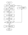
- FIG. 11 is a flowchart showing a method for manufacturing a three-dimensional structure according to the first embodiment of the present invention.
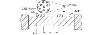
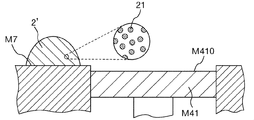
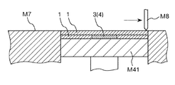
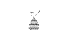
- the manufacturing method of the three-dimensional structure 10 of this embodiment is a method of manufacturing the three-dimensional structure 10 by laminating a plurality of layers 1, and includes a plurality of particles 21.
- (Composition) Layer formation step (see FIGS. 1, 2, 5, and 6) for forming the layer 1 using 2 ′, and particles contained in the layer 1 by irradiating the layer 1 with the laser beam L
- a series of steps including a joining step (see FIGS. 3, 4, 7, and 8) for joining 21 to each other is repeated (see FIG. 9).
- the arithmetic average height Sa (ISO 25178) of the surface of the layer 1 in a state where the particles 21 are bonded to each other by the bonding step is 15 ⁇ m or less.
- particles 21 or a melt thereof (hereinafter also simply referred to as “particles 21 or the like”) is scattered or voids (holes or voids) are formed inside the three-dimensional structure 10. It is possible to effectively prevent a reduction in the dimensional accuracy of the three-dimensional structure 10 or a decrease in the strength of the three-dimensional structure 10, and to manufacture the three-dimensional structure 10 having excellent reliability.
- the manufacturing method of the three-dimensional structure 10 which can be provided can be provided.
- the energy causes the particles to be ejected from the initial position of the layer or a liquid pool of the particles ( As the molten pool) undulates and the laser beam is scanned, the melt may be ejected, causing unintended irregularities on the surface of the layer after laser beam irradiation, and finally obtaining the tertiary
- the dimensional accuracy of the original model was lowered.
- the average particle diameter D 50 of the particles and the thickness D S of the layer formed in the layer forming step satisfy a predetermined relationship (D S / D 50 ⁇ 5.0).
- the conditions regarding the arithmetic average height Sa of the surface of the layer formed by the above joining processes should just be satisfied at least in the region corresponding to the substantial part of the three-dimensional structure to be manufactured.
- the region corresponding to the support portion 5 may not satisfy the condition for the arithmetic average height Sa as described above. It is preferable that both the area corresponding to the entity part 4 and the area corresponding to the support part 5 satisfy the condition regarding the arithmetic average height Sa as described above. Thereby, the effects as described above are more remarkably exhibited.
- the average particle diameter means a volume-based average particle diameter.
- a dispersion obtained by adding a sample to methanol and dispersing for 3 minutes with an ultrasonic disperser is used as a Coulter counter particle size distribution analyzer (COULTER ELECTRONICS). It can be determined by measuring with a 50 ⁇ m aperture using an INS TA-II type).
- the ratio of the layer thickness D S to the average particle diameter D 50 of the particles (D S / D 50 ) is too large, scattering of particles or the like when irradiated with laser light, or the inside of the three-dimensional structure Air gaps (holes, voids) are likely to occur.
- the value of D S / D 50 by D S is a large value is large, in the thickness direction (height direction), it is difficult to produce a precise three-dimensional shaped object than the thickness of the layer, As a result, the dimensional accuracy of the three-dimensional structure decreases.
- D S / D 50 by D 50 is smaller is high, scattering and particle like when irradiated with laser light as described above, voids in the interior of the three-dimensional model ( The generation of vacancies and voids becomes more prominent.
- liquidity of the composition for three-dimensional structure manufacture falls, the ease of handling of the composition for three-dimensional structure manufacture falls, and the productivity of a three-dimensional structure falls.
- the value of D 50 is particularly small, tends to occur agglomeration of the particles in the 3D object for producing a composition, in a stage before the laser irradiation, it tends to occur undesirable unevenness of the surface of the layer Become.
- the dimensional accuracy of the three-dimensional structure is particularly low, coupled with the influence of scattering of particles and the like when irradiated with laser light.
- the arithmetic average height Sa of the surface of the layer in a state where the particles are bonded by the bonding process is too large, the unevenness existing on the surface of the layer has a large effect on the shape of the layer formed on the upper surface of the layer. The dimensional accuracy of the finally obtained three-dimensional structure decreases.
- D S / D 50 ⁇ 5.0 when the average particle diameter of the particles 21 is D 50 [ ⁇ m] and the thickness of the layer 1 formed in the layer forming step is D S [ ⁇ m], D S / D 50 ⁇ 5.0.
- the relationship may be satisfied, but it is preferable that the relationship of 1.0 ⁇ D S / D 50 ⁇ 4.0 is satisfied, and the relationship of 1.2 ⁇ D S / D 50 ⁇ 3.5 is satisfied. More preferably, it is more preferable that the relationship of 1.4 ⁇ D S / D 50 ⁇ 3.0 is satisfied. Thereby, the effects as described above are more remarkably exhibited.
- the arithmetic average height Sa of the surface of the layer 1 in a state where the particles 21 are bonded to each other by the bonding process may be 15 ⁇ m or less, preferably 11 ⁇ m or less, and preferably 8.0 ⁇ m or less. More preferably, it is more than 0 ⁇ m and 5.0 ⁇ m or less. Thereby, the effects as described above are more remarkably exhibited.
- the configuration of the composition 2 ′ for manufacturing a three-dimensional structure more specifically, For example, the constituent material of the particles 21, the particle size, the particle size distribution, etc., the thickness of the layer 1 formed in the layer forming step, the irradiation conditions of the laser light L (for example, the type of the laser light L, the beam diameter of the laser light L) Scanning speed, laser output, etc.).
- composition 2 'for three-dimensional structure manufacture what contains the solvent which functions as a dispersion medium which disperse
- a solvent removal process is provided between the layer formation process and the bonding process.
- liquidity of composition 2 'for three-dimensional structure manufacture is made favorable, and the ease of handling of composition 2' for three-dimensional structure manufacture and the ease of formation of layer 1 are improved. Can do. Further, the flatness of the formed layer 1 can be made better.
- a solvent is a liquid (dispersion medium) which can disperse
- the layer 1 is formed by discharging the composition 2 ′ for manufacturing a three-dimensional structure.
- the layer 1 is formed by a discharge method.
- 3D modeling composition 2 ' can be provided with the pattern corresponding to the cross-sectional shape etc. of the three-dimensional modeling thing 10 which should be manufactured, and the three-dimensional modeling object 10 which has a finer structure also. It can manufacture suitably. Moreover, according to the cross-sectional area of the three-dimensional structure 10 to be manufactured, the application amount of the composition 2 ′ for manufacturing a three-dimensional structure in each layer 1 can be suitably adjusted, and the composition 2 for manufacturing a three-dimensional structure 2 The amount of use can be suppressed.
- waste of the composition 2 ′ for manufacturing the three-dimensional structure can be suppressed, and the recovery of the composition 2 ′ for manufacturing the three-dimensional structure 2 ′ that has not been used for manufacturing the three-dimensional structure 10 can be performed. It can be omitted or simplified.
- Such an effect is obtained when the cross-sectional area of the three-dimensional structure 10 to be manufactured is particularly small compared to the area of the stage M41 (for example, the cross-sectional area of the three-dimensional structure 10 to be manufactured is equal to the area of the stage M41). In the case of 1/10 or less, etc.).
- the discharge method refers to a method of forming a pattern corresponding to a layer by discharging a composition (a composition for producing a three-dimensional structure) in a predetermined pattern, and a supplied composition. It is distinguished from a method of forming a layer by flattening an object with a squeegee, a roller or the like (method of a second embodiment described later).
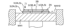
- composition 2B ' (particulate formation composition 2B' (particle
- composition 2A ′ composition containing composition (particle (dispersoid) used for forming the support portion (support portion, support material) 5 that supports the portion to be the substantial portion 4)
- composition containing 21A A composition containing 21A).
- a first pattern forming step (support portion pattern forming step) in which a support portion forming composition (composition) 2A ′ is discharged to form a first pattern (support portion pattern) 2A;
- a second pattern forming step (substantive portion pattern forming step) for discharging the forming composition (composition) 2B ′ to form a second pattern (substance portion pattern) 2B.
- the dimensional accuracy of the three-dimensional structure 10 can be further improved.
- even the three-dimensional structure 10 having a more complicated shape can be suitably manufactured.
- the layer 1 in which at least one of the composition 2B ′ for forming the substantial part as the composition 2 ′ for manufacturing the three-dimensional structure 2A ′ and the composition 2A ′ for supporting part formation is formed in the layer forming step.
- the above-described conditions (the relationship of D S / D 50 ⁇ 5.0) are satisfied. Thereby, the reliability of the three-dimensional structure 10 can be further improved.
- First pattern formation process the support portion forming composition 2A ′ is discharged onto, for example, the plane M410 of the stage M41 to form the first pattern 2A.
- the first pattern 2A by discharging the support portion forming composition 2A ', even a pattern having a fine shape or a complicated shape can be suitably formed.
- the method for discharging the support portion forming composition 2A ' is not particularly limited, and for example, it may be performed using an ink jet apparatus or the like, but is preferably discharged by a dispenser.
- the support portion forming composition 2A ′ may be in a paste form, for example.
- the viscosity of the support portion forming composition 2A ′ in this step is preferably from 100 mPa ⁇ s to 1,000,000 mPa ⁇ s, more preferably from 500 mPa ⁇ s to 100,000 mPa ⁇ s, and more preferably from 1000 mPa ⁇ s to 20,000 mPa ⁇ s. More preferably, it is s or less.
- the discharge stability of the support portion forming composition 2A ′ can be further improved, and it is suitable for forming the layer 1 having an appropriate thickness, and the productivity of the three-dimensional structure 10 is improved. It can be improved further.
- the support portion forming composition 2A ′ in contact with the adherend is more effectively prevented from spreading excessively, and the dimensional accuracy of the finally obtained three-dimensional structure 10 can be further improved. .
- the viscosity means a value measured using a rheometer under the condition of shear rate: 10 [s ⁇ 1 ] unless otherwise specified.
- the support portion forming composition 2A ′ may be discharged in a continuous form or as a plurality of droplets, but is preferably discharged as a plurality of droplets.
- the volume per droplet of the discharged droplets is preferably 1 pL or more and 100000 pL (100 nL) or less, and preferably 10 pL or more and 50000 pL. (50 nL) or less is more preferable.
- the dimensional accuracy of the three-dimensional structure 10 can be further improved, and the three-dimensional structure 10 The productivity can be further improved.
- compositions may be used as the support portion forming composition 2 ⁇ / b> A ′.
- the support portion forming composition 2A ′ will be described in detail later.
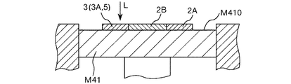
- Second pattern formation process In the second pattern forming step, the entity pattern forming composition 2B ′ is discharged to form the second pattern 2B.
- the second pattern 2B by discharging the substance forming composition 2B ', even a pattern having a fine shape or a complicated shape can be suitably formed.
- the composition for forming a substantial part 2B ′ is ejected to a region surrounded by the first pattern 2A so that the entire periphery of the second pattern 2B is in contact with the first pattern 2A. To do.
- the method for discharging the substance forming composition 2B ' is not particularly limited, and for example, it can be performed using an ink jet apparatus or the like, but is preferably discharged by a dispenser.
- the entity forming composition 2B ′ may be in the form of a paste, for example.
- the viscosity of the entity forming composition 2B ′ in this step is preferably from 100 mPa ⁇ s to 1000000 mPa ⁇ s, more preferably from 500 mPa ⁇ s to 100000 mPa ⁇ s, more preferably from 1000 mPa ⁇ s to 20000 mPa ⁇ s. More preferably, it is s or less.
- the substance forming composition 2B ′ may be ejected in a continuous form or a plurality of droplets, but is preferably ejected as a plurality of droplets.
- the volume per droplet of the ejected droplets is preferably 1 pL or more and 100000 pL (100 nL) or less, preferably 10 pL or more and 50000 pL. (50 nL) or less is more preferable.
- the dimensional accuracy of the three-dimensional structure 10 can be further improved, and the three-dimensional structure 10 The productivity can be further improved.
- composition 2B ' In the production of the three-dimensional structure 10, a plurality of types of compositions may be used as the entity forming composition 2B '.
- materials can be combined according to characteristics required for each part of the three-dimensional structure 10, and characteristics (appearance, functionality (for example, elasticity, toughness, heat resistance) of the three-dimensional structure 10 as a whole. And the like) and the like can be further improved.
- the layer forming process includes a first pattern forming process and a second pattern forming process.
- the thickness D S of the layer 1 formed by a layer forming step is not particularly limited, but is preferably 5 ⁇ m or 300 ⁇ m or less, more preferably at 10 ⁇ m or 200 ⁇ m or less, at 20 ⁇ m or 100 ⁇ m or less Further preferred.
- the reliability (particularly, dimensional accuracy, strength, etc.) of the three-dimensional structure 10 can be further improved.
- the fluidity of the layer 1 is lowered and the stability of the shape of the layer 1 is improved.
- this step it is possible to effectively prevent unintentional deformation caused by rapid volatilization (such as bumping) of the solvent in the subsequent bonding step. From the above, it is possible to obtain the three-dimensional structure 10 having more reliable reliability (for example, dimensional accuracy, strength, etc.) and improve the productivity of the three-dimensional structure 10 more reliably. it can.
- a gas having a low content of liquid components such as dry air (for example, A gas having a relative humidity of 30% or less).
- a gas having a relative humidity of 30% or less for example, you may carry out combining 2 or more types selected from these.
- a solvent removal step (first solvent removal step) is performed on the first pattern 2A completed in the first pattern formation step, and then the second pattern 2B completed in the second pattern formation step
- a solvent removing step (second solvent removing step) may be performed.
- the content of the solvent in the layer 1 after this step is preferably 0.1% by mass or more and 25% by mass or less, and more preferably 0.5% by mass or more and 20% by mass or less.
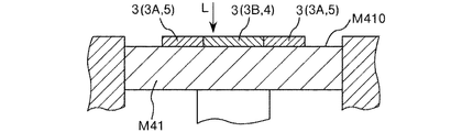
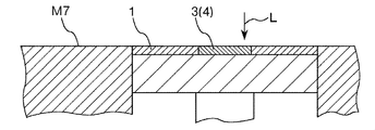
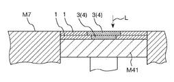
- the layer 1 is irradiated (scanned) with the laser beam L (see FIGS. 3, 4, 7, and 8).
- the particles 21 included in the composition 2 ′ for manufacturing a three-dimensional structure are bonded to each other, and the bonded portion 3 is formed.
- the joint portion 3 By forming the joint portion 3 in this way, the subsequent unintentional movement of the particles 21 is prevented, and the dimensional accuracy and strength of the three-dimensional structure 10 can be improved.
- the particles 21 are generally joined with sufficient joint strength.
- the layer 1 having the bonding portion 3 formed on the lower side of the layer 1 irradiated with the laser beam L generally, the bonding portion 3 of the lower layer 1; The newly formed joint 3 is joined. For this reason, the mechanical strength of the finally obtained three-dimensional structure 10 can be improved.
- the laser beam L energy can be imparted to a desired part with high selectivity, which is advantageous in improving the dimensional accuracy of the three-dimensional structure 10 and the three-dimensional structure 10. This is also advantageous in improving the productivity. Moreover, energy efficiency can be improved and it is advantageous also from an energy-saving viewpoint.
- the particles 21 are joined by irradiation with the laser beam L, and unnecessary components other than the particles 21 can be removed.
- unnecessary components other than the particles 21 can be removed.
- a binder, a solvent, etc. can be removed and it can prevent effectively that these components remain in the junction part 3 formed.
- the joining step is performed so that the arithmetic average height Sa of the surface of the layer 1 in a state where the particles 21 are joined by this step (joining step) is 15 ⁇ m or less, the joining portion 3 is formed.
- the flatness of the surface of the formed layer 1 can be made excellent.
- irradiation is performed by using the composition 2 ′ for manufacturing a three-dimensional structure that satisfies the above-described conditions (the relationship of D S / D 50 ⁇ 5.0) with the layer 1 formed in the layer forming step. Unintentional scattering of the particles 21 and the like due to the energy of the laser light L is effectively prevented. Therefore, the three-dimensional structure 10 having excellent reliability (dimensional accuracy, strength, etc.) can be obtained.
- the form of joining varies depending on the constituent material of the particles 21, and examples thereof include fusion, sintering, and melt solidification.
- a joining process irradiates laser beam L with respect to 1st pattern 2A formed using composition 2A 'for support part formation, and joins particle
- the first bonding step for forming 3A and the second pattern 2B formed using the composition for forming a substantial part 2B ′ are irradiated with laser light L to bond the particles 21B together.
- the joint portion (second joint portion) 3B is formed in the portion that becomes the substantial portion 4 of the three-dimensional structure 10 and functions as the support portion 5 in the manufacturing process of the three-dimensional structure 10.
- a joining portion (first joining portion) 3A to be formed is formed.
- the stability of the shape of the supporting portion 5 to be supported can be further improved, the occurrence of unintentional deformation in the manufacturing process of the three-dimensional structure 10 can be more effectively prevented, and finally obtained tertiary
- the dimensional accuracy of the original shaped article 10 can be further improved.
- lasers examples include solid lasers such as ruby lasers, YAG lasers, Nd: YAG lasers, titanium sapphire lasers, and semiconductor lasers; liquid lasers such as dye lasers; neutral atom lasers (helium neon lasers) Gas lasers such as ion laser (argon ion laser, etc.), molecular laser (carbon dioxide laser, nitrogen laser, etc.), excimer laser, metal vapor laser (helium cadmium laser, etc.); free electron laser; oxygen-iodine chemical laser And chemical lasers such as hydrogen fluoride laser; fiber lasers and the like.
- solid lasers such as ruby lasers, YAG lasers, Nd: YAG lasers, titanium sapphire lasers, and semiconductor lasers
- liquid lasers such as dye lasers
- neutral atom lasers helium neon lasers
- Gas lasers such as ion laser (argon ion laser, etc.), molecular laser (carbon dioxide laser, nitrogen laser, etc.), excimer laser, metal
- the thickness of the layer 1 having the joint portion 3 is not particularly limited, but is preferably 5 ⁇ m or more and 300 ⁇ m or less, more preferably 10 ⁇ m or more and 200 ⁇ m or less, and further preferably 20 ⁇ m or more and 100 ⁇ m or less.
- the reliability (dimensional accuracy, strength, etc.) of the three-dimensional structure 10 can be further improved while improving the productivity of the three-dimensional structure 10.
- the irradiation conditions of the laser beam L may be adjusted to be different in each part of the layer 1.
- the irradiation condition of the laser beam L so that the bonding strength of the particles 21A in the bonding portion 3A (support material 5) is smaller than the bonding strength of the particles 21B in the bonding portion 3B (substance portion 4). (Irradiation energy etc.) may be adjusted.
- productivity of the three-dimensional structure 10 can be improved more, and the three-dimensional structure 10 in the support material removal process can be improved.
- the occurrence of defects can be prevented more effectively, and the reliability (such as dimensional accuracy) of the finally obtained three-dimensional structure 10 can be further improved.
- the surface of the layer 1 in a state where the particles 21 are bonded to each other by the bonding process (the surface of the layer 1 after the bonding process) satisfies the conditions for the arithmetic average height Sa (ISO 25178) as described above. What is necessary is just to satisfy, but it is preferable to satisfy the following conditions further.
- the maximum height Sz (ISO 25178) of the surface of the layer 1 in a state where the particles 21 are bonded by the bonding process is preferably 250 ⁇ m or less, more preferably 200 ⁇ m or less, and more than 0 ⁇ m and 150 ⁇ m or less. More preferably.
- the root mean square height Sq (ISO 25178) of the surface of the layer 1 in a state where the particles 21 are bonded by the bonding process is preferably 30 ⁇ m or less, more preferably 20 ⁇ m or less, and more than 0 ⁇ m. More preferably, it is 15 ⁇ m or less.
- the skewness deviation degree Ssk (ISO 25178) of the surface of the layer 1 in a state where the particles 21 are bonded by the bonding process is preferably ⁇ 1.0 or more and 2.0 or less, and ⁇ 0.5 or more and 1 It is more preferably 0.5 or less, and further preferably ⁇ 0.3 or more and 1.0 or less.
- the kurtosis kurtosis Sku (ISO 25178) of the surface of the layer 1 in a state where the particles 21 are bonded to each other by the bonding step is preferably 15 or less, more preferably 10 or less, and more than 0. More preferably, it is 0 or less.
- the maximum peak height Sp (ISO 25178) of the surface of the layer 1 in a state where the particles 21 are bonded by the bonding process is preferably 200 ⁇ m or less, more preferably 150 ⁇ m or less, and more than 0 ⁇ m and 70 ⁇ m or less. More preferably.
- the maximum valley depth Sv (ISO 25178) of the surface of the layer 1 in a state where the particles 21 are bonded by the bonding process is preferably 150 ⁇ m or less, more preferably 100 ⁇ m or less, and more than 0 ⁇ m and 50 ⁇ m. More preferably, it is as follows.
- the conditions (maximum height Sz, skewness bias degree Ssk, kurtosis sharpness Sku, maximum peak height Sp, maximum valley depth Sv) about the surface of the layer 1 after the joining process as described above are the three-dimensional structures to be manufactured. It is preferable that the area corresponding to the entity part 4 is satisfied, but it is more preferable that both the area corresponding to the entity part 4 and the area corresponding to the support part 5 are satisfied. Thereby, the effects as described above are more remarkably exhibited.
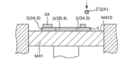
- ⁇ Support part removal process In the present embodiment, after a series of steps including a layer forming step (first pattern forming step and second pattern forming step), a solvent removing step and a bonding step are repeatedly performed (see FIG. 9), as a post-processing step Then, the support material 5 is removed (see FIG. 10). Thereby, the three-dimensional structure 10 is taken out.
- Specific examples of the process include a method of dissolving at least a part of the support material 5 and a method of breaking the support material 5 by breaking it.
- a series of steps including a layer formation step (first pattern formation step and second pattern formation step), a solvent removal step and a bonding step are repeated a predetermined number of times, and a plurality of layers A laminate in which 1 is laminated is obtained.
- a support part removing step as post-processing is performed on the laminated body to obtain a target three-dimensional structure 10.
- the above-described series of steps is performed once to form one layer 1.
- the above-described series of steps may be repeated to form one layer.
- the layer forming step (first pattern forming step) or the bonding step for the support portion forming composition 2A ′ the layer forming step (second pattern forming step) for the substantial portion forming composition 2B ′.
- one layer may be formed by performing a bonding process.
- the particles 21 and the like are scattered in the manufacturing process of the three-dimensional structure 10 and that voids (holes and voids) are formed inside the three-dimensional structure 10.
- the three-dimensional structure 10 having excellent reliability (dimensional accuracy, strength, etc.) can be efficiently manufactured.
- composition for three-dimensional structure production Next, the composition for manufacturing a three-dimensional structure used in the manufacturing method of the embodiment described above will be described.
- the layer 1 in which at least one type of three-dimensional structure manufacturing composition 2 ′ is formed in the layer forming step is formed in the layer forming step.
- the above-described conditions the relationship of D S / D 50 ⁇ 5.0
- the substantial part forming composition 2B ′ and the support part forming composition 2A ′ satisfy the above-mentioned conditions (the relationship of D S / D 50 ⁇ 5.0) with the layer 1 formed in the layer forming step. More preferably.
- the three-dimensional structure 10 having excellent reliability can be manufactured.
- composition for producing a three-dimensional structure a composition 2B 'for forming an entity part and a composition 2A' for forming a support part are used.
- composition 2B ′ As a three-dimensional structure manufacturing composition used for manufacturing the three-dimensional structure 10 will be described.
- the constituent part forming composition 2B ′ is not particularly limited as long as it can be used to form the substantial part 4 (formation of the second pattern 2B), but a plurality of particles 21B (main material particles) are not particularly limited. And the above-described conditions (the relationship of D S / D 50 ⁇ 5.0) with the layer 1 formed in the layer forming step are preferably satisfied.
- composition for forming an entity part 2B ′ includes the plurality of particles 21B and the above-described conditions (D S / D 50 ⁇ 5. 5) with the layer 1 formed in the layer forming step. A case where the relationship of 0) is satisfied will be described representatively.
- the range of selection of the constituent material of the three-dimensional structure 10 can be expanded, and the three-dimensional structure having desired physical properties, textures, and the like. 10 can be suitably obtained.
- the material that can be used there are limitations on the material that can be used, but by using the composition for forming an entity part 2B ′ including the particles 21B, Limits can be removed.
- Examples of the constituent material of the particles 21 ⁇ / b> B included in the substance forming composition 2 ⁇ / b> B ′ include metal materials, metal compounds (ceramics, etc.), resin materials, pigments, and the like.
- composition 2B ' preferably includes metal particles made of a material including a metal material.
- the texture (luxury feeling, weight feeling), mechanical strength, toughness, durability and the like of the three-dimensional structure 10 can be further improved.
- heat transfer at the time of applying energy for joining the particles 21B proceeds efficiently, unintentional variations in temperature at each part are generated while improving the productivity of the three-dimensional structure 10. It can prevent more effectively and can improve the reliability of the three-dimensional structure 10 more.
- Examples of the metal material constituting the particles 21B include magnesium, iron, copper, cobalt, titanium, chromium, nickel, aluminum and alloys containing at least one of these (for example, maraging steel, stainless steel, cobalt chromium molybdenum). , Titanium alloys, nickel-based alloys, aluminum alloys, etc.).
- Examples of the metal compound constituting the particle 21B include various metal oxides such as silica, alumina, titanium oxide, zinc oxide, zircon oxide, tin oxide, magnesium oxide, and potassium titanate; magnesium hydroxide, aluminum hydroxide, water Various metal hydroxides such as calcium oxide; various metal nitrides such as silicon nitride, titanium nitride and aluminum nitride; various metal carbides such as silicon carbide and titanium carbide; various metal sulfides such as zinc sulfide; calcium carbonate and magnesium carbonate Carbonate of various metals such as calcium sulfate, sulfate of various metals such as magnesium sulfate, silicate of various metals such as calcium silicate and magnesium silicate, phosphate of various metals such as calcium phosphate, aluminum borate , Borate salts of various metals such as magnesium borate, and composites of these It is.
- various metal oxides such as silica, alumina, titanium oxide, zinc oxide, zircon
- Examples of the resin material constituting the particles 21B include polybutylene terephthalate, polyethylene terephthalate, polypropylene, polystyrene, syndiotactic polystyrene, polyacetal, modified polyphenylene ether, polyether ether ketone, polycarbonate, acrylonitrile-butadiene-styrene copolymer. (ABS resin), polyether nitrile, polyamide (nylon, etc.), polyarylate, polyamide imide, polyether imide, polyimide, liquid crystal polymer, polysulfone, polyether sulfone, polyphenylene sulfide, fluorine resin and the like.
- ABS resin polybutylene terephthalate
- polyethylene terephthalate polypropylene
- polystyrene syndiotactic polystyrene
- polyacetal modified polyphenylene ether
- polyether ether ketone polycarbonate
- the shape of the particle 21B is not particularly limited, and may be any shape such as a spherical shape, a spindle shape, a needle shape, a cylindrical shape, a scale shape, or an indefinite shape, but it is spherical. preferable.
- the average particle diameter of the particles 21B is not particularly limited, but is preferably 0.1 ⁇ m or more and less than 50 ⁇ m, more preferably 0.2 ⁇ m or more and 20 ⁇ m or less, and further preferably 0.3 ⁇ m or more and 10 ⁇ m or less. .
- the fluidity of the entity forming composition 2B ′ decreases, and the ease of handling of the entity forming composition 2B ′ decreases.
- the productivity of the three-dimensional structure 10 decreases. Further, scattering of particles and the like when irradiated with the laser beam L is likely to occur, and the dimensional accuracy of the three-dimensional structure 10 is likely to be reduced, or voids (holes, voids) are formed inside the three-dimensional structure 10. It tends to occur.
- the particles 21B tend to aggregate in the substance forming composition 2B ′, and the surface of the layer 1 is unintentionally in the stage before the irradiation with the laser beam L. Unevenness is likely to occur. As a result, the dimensional accuracy of the three-dimensional structure 10 tends to decrease particularly in combination with the influence of scattering of particles and the like when the laser beam L is irradiated.
- the dimensional accuracy of the three-dimensional structure 10 decreases due to the effect of easily forming irregularities on the surface of the layer 1 due to the size of the particles 21B itself. It becomes easy to do. In addition, it becomes difficult to sufficiently melt the particles 21 ⁇ / b> B, and voids (holes, voids) are easily generated inside the three-dimensional structure 10.
- the volume-based average particle diameter of the particles 21B is preferably 0.1 ⁇ m or more and 10 ⁇ m or less. It is more preferably 2 ⁇ m or more and 7.0 ⁇ m or less, and further preferably 0.3 ⁇ m or more and 4.0 ⁇ m or less.
- the reliability (dimensional accuracy, strength, etc.) of the manufactured three-dimensional structure 10 can be further improved while further improving the productivity of the three-dimensional structure 10.
- the Dmax of the particle 21B is preferably 0.2 ⁇ m or more and 80 ⁇ m or less, more preferably 0.4 ⁇ m or more and 40 ⁇ m or less, and further preferably 0.5 ⁇ m or more and 20 ⁇ m or less.
- the fluidity of the composition 2B ′ for forming the substantial part becomes more suitable, the second pattern forming process can be performed more smoothly, and the bonding of the particles 21B in the bonding process is more preferably performed. Can do.
- the strength of the manufactured three-dimensional structure 10 can be further improved, and the occurrence of unintentional irregularities in the manufactured three-dimensional structure 10. Etc. can be more effectively prevented, and the dimensional accuracy of the three-dimensional structure 10 can be further improved.
- the content ratio of the particles 21B in the substantial part forming composition 2B ′ is preferably 30% by mass to 95% by mass, and more preferably 35% by mass to 92% by mass.
- the particles 21B are made of a material that undergoes a chemical reaction (for example, an oxidation reaction) in the manufacturing process (for example, a bonding step) of the three-dimensional structure 10 and is contained in the substance forming composition 2B ′.
- the composition of the particles 21 ⁇ / b> B included in the structure and the constituent material of the final three-dimensional structure 10 may be different.
- the entity forming composition 2B ′ may contain two or more kinds of particles 21B.
- the particles 21B can be suitably dispersed in the entity forming composition 2B ′, and the entity forming composition 2B using a dispenser or the like can be used. 'Can be discharged stably.
- the solvent is not particularly limited as long as it has a function of dispersing the particles 21B (function as a dispersion medium) in the composition for forming an entity part 2B ′.
- a dispersion medium for example, water; ethylene glycol monomethyl ether, ethylene glycol mono Ethers such as ethyl ether, propylene glycol monomethyl ether, propylene glycol monoethyl ether, diethyl diglycol, diethylene glycol monobutyl ether acetate; ethyl acetate, n-propyl acetate, iso-propyl acetate, n-butyl acetate, iso-butyl acetate, etc.
- Acetates such as carbitols such as carbitol and its ester compounds (for example, carbitol acetate); cellosolobs such as cellosorb and its ester compounds (for example, cellosorob acetate); benzene Aromatic hydrocarbons such as toluene and xylene; ketones such as methyl ethyl ketone, acetone, methyl isobutyl ketone, ethyl-n-butyl ketone, diisopropyl ketone, and acetylacetone; monohydric alcohols such as ethanol, propanol, and butanol, ethylene glycol, propylene Alcohols such as polyhydric alcohols such as glycol, butanediol and glycerin; sulfoxide solvents such as dimethyl sulfoxide and diethyl sulfoxide; pyridine, picoline ( ⁇ -picoline, ⁇ -picoline, ⁇
- Pyridine-based solvents such as tetraalkylammonium acetate (for example, tetrabutylammonium acetate, etc.), and the like can be used alone or in combination of two or more.
- Rukoto can be used alone or in combination of two or more.
- the content of the solvent in the substantial part forming composition 2B ′ is preferably 5% by mass or more and 70% by mass or less, and more preferably 8% by mass or more and 65% by mass or less.
- the productivity of the three-dimensional structure 10 can be further improved while further improving the ease of handling the composition 2B ′ for forming the substantial part, and from the viewpoint of production cost, resource saving, and the like. Is also particularly advantageous. Moreover, the dimensional accuracy of the finally obtained three-dimensional structure 10 can be further improved.
- the entity forming composition 2B ′ may include a binder having a function of temporarily bonding the particles 21B to each other in a state where the solvent is removed.
- the binder for forming the substantial part 2B ′ for example, it is possible to more effectively prevent unintentional deformation of the second pattern 2B formed using the composition 2B ′ for forming the substantial part. it can. Moreover, the unintentional scattering of the particles 21B and the melt thereof when the laser beam L is irradiated in the joining step can be more effectively prevented. Thereby, generation
- the binder only needs to have a function of temporarily fixing the particles 21B in the composition 2B ′ (second pattern 2B) for forming the substantial part before being subjected to the joining step.
- a thermoplastic resin Various resin materials such as a curable resin can be used.
- the curing reaction of the curable resin may be performed at a timing after the ejection of the entity forming composition 2 ⁇ / b> B ′ and before the joining step.
- the curing treatment for causing the curing reaction of the curable resin to proceed can be performed by, for example, heating or irradiation with energy rays such as ultraviolet rays.
- thermosetting resins and photocurable resins can be suitably used.
- binder examples include acrylic resin, epoxy resin, silicone resin, polyvinyl alcohol, PLA (polylactic acid), PA (polyamide), PPS (polyphenylene sulfide), and the like.
- the binder may be contained in any form, but the entity part forming composition 2B ′ is in a liquid state (for example, a molten state, a dissolved state, etc.) as a binder.
- a liquid state for example, a molten state, a dissolved state, etc.
- it contains the components. That is, it is preferable that at least a part of the binder is contained as a constituent component of the dispersion medium.
- the binder can function as a dispersion medium for dispersing the particles 21 ⁇ / b> B, and can further improve the storage stability of the entity forming composition 2 ⁇ / b> B ′.
- composition 2B ' may contain nanocellulose as a binder.
- Nanocellulose is a fibrous substance composed of cellulose or a cellulose derivative and having a width and thickness of 100 nm or less, and is a concept including so-called cellulose nanofibers and cellulose nanocrystals.
- the viscosity of the whole entity forming composition 2B ' can be adjusted to a suitable range with a relatively low content.
- the viscosity of the substantial part forming composition 2B ′ is sufficiently high without increasing the content ratio of the particles 21B and the content ratio of the binder other than nanocellulose in the substantial part forming composition 2B ′. can do. Therefore, it is possible to effectively prevent the unintentional aggregation of the particles 21B in the entity forming composition 2B ′ and the unintentional composition variation in the entity forming composition 2B ′ or the three-dimensional structure 10. However, unintentional deformation of the layer 1 can be prevented.
- the entity forming composition 2B ′ containing nanocellulose has thixotropy, and in a state where shear stress is applied as in ejection, the viscosity of the entity forming composition 2B ′ decreases and is stable. Discharge can be performed. Moreover, since the amount of the binder contained in the composition 2B ′ for forming the substantial part can be reduced, the binder and its decomposition product remain unintentionally in the finally obtained three-dimensional structure 10. This can be prevented more effectively. Moreover, from the above, the reliability of the three-dimensional structure 10 can be further improved.
- the binder content in the entity forming composition 2B ′ exceeds the upper limit, the proportion of the particles 21B in the solid content of the entity forming composition 2B ′ tends to be relatively low.
- the volume reduction rate due to bumping at the time of laser irradiation in the manufacturing process of the three-dimensional structure 10 increases, and the dimensional accuracy of the finally obtained three-dimensional structure 10 tends to decrease.
- the content of impurities (for example, carbon) derived from the binder may be high.
- composition 2B ′ may contain components other than those described above.
- examples of such components include a polymerization initiator; a dispersant; a surfactant; a thickener; an agglomeration inhibitor; an antifoaming agent; a slip agent (leveling agent); a dye; a polymerization inhibitor; Accelerators; humectants (humectants); fixing agents; antifungal agents; antiseptics; antioxidants; ultraviolet absorbers; chelating agents;
- the support portion forming composition 2A ′ can be used for forming the support portion 5 (formation of the first pattern 2A), its constituent components and the like are not particularly limited, but a plurality of particles 21A (main material particles). And the above-described conditions (the relationship of D S / D 50 ⁇ 5.0) with the layer 1 formed in the layer forming step are preferably satisfied.
- the support portion forming composition 2A ′ includes the plurality of particles 21A and the above-described conditions (D S / D 50 ⁇ 5. 5) with the layer 1 formed in the layer forming step. A case where the relationship of 0) is satisfied will be described representatively.
- the support part 5 to be formed (first pattern 2A) has a fine shape by including the plurality of particles 21A in the support part forming composition 2A ′, the support part 5 is formed. It can be formed efficiently with high dimensional accuracy. Moreover, a solvent and a binder (a decomposition product is included) can be efficiently removed from the clearance gap between the some particle
- the particles 21A constituting the support portion forming composition 2A ' are preferably made of a material having a higher melting point than the particles 21B constituting the substantial portion forming composition 2B'.
- the shape of the particle 21A is not particularly limited, and may be any shape such as a spherical shape, a spindle shape, a needle shape, a cylindrical shape, a scale shape, or an indefinite shape, but it is spherical. preferable.
- the average particle diameter of the particles 21A is not particularly limited, but is preferably 0.1 ⁇ m or more and less than 50 ⁇ m, more preferably 0.2 ⁇ m or more and 20 ⁇ m or less, and further preferably 0.3 ⁇ m or more and 10 ⁇ m or less. .
- the average particle size of the particles 21A is less than the lower limit, the fluidity of the support portion forming composition 2A ′ is lowered, and the supportability of the support portion forming composition 2A ′ is lowered.
- the productivity of the three-dimensional structure 10 decreases.
- scattering of particles and the like when irradiated with the laser beam L is likely to occur, and the dimensional accuracy of the three-dimensional structure 10 is likely to be lowered.
- the average particle diameter of the particles 21A is particularly small, the particles 21A are likely to aggregate in the support portion forming composition 2A ′, and the surface of the layer 1 is unintentionally in the stage before the irradiation with the laser beam L. Unevenness is likely to occur.
- the dimensional accuracy of the three-dimensional structure 10 tends to decrease particularly in combination with the influence of scattering of particles and the like when the laser beam L is irradiated.
- the dimensional accuracy of the three-dimensional structure 10 decreases due to the fact that the surface of the layer 1 is likely to be uneven due to the size of the particles 21A itself. It becomes easy to do.
- Dmax of the particle 21A is preferably 0.2 ⁇ m or more and 80 ⁇ m or less, more preferably 0.4 ⁇ m or more and 40 ⁇ m or less, and further preferably 0.5 ⁇ m or more and 20 ⁇ m or less.
- the solvent and binder (including decomposition products) can be more efficiently removed from the gaps between the plurality of particles 21 ⁇ / b> A constituting the support portion 5 (first pattern 2 ⁇ / b> A), and the three-dimensional structure 10 can be produced. The property can be further improved.
- the content ratio of the particles 21A in the support portion forming composition 2A ′ is preferably 30% by mass or more and 95% by mass or less, and more preferably 35% by mass or more and 92% by mass or less.
- the particles 21A are made of a material that undergoes a chemical reaction (for example, an oxidation reaction) in the manufacturing process (for example, a bonding step) of the three-dimensional structure 10, and in the support portion forming composition 2A ′.
- the composition of the particles 21 ⁇ / b> A included in the material and the constituent material of the final three-dimensional structure 10 may be different.
- the support portion forming composition 2A ′ may include two or more kinds of particles 21A.
- the support portion forming composition 2A ′ contains a solvent, whereby the particles can be suitably dispersed in the support portion forming composition 2A ′, and the discharge of the support portion forming composition 2A ′ by a dispenser or the like is stable. Can be done automatically.
- Examples of the solvent contained in the support portion forming composition 2A ′ include the same solvents as those described as the constituent material of the substantial portion forming composition 2B ′. Thereby, the same effect as described above can be obtained.
- composition of the solvent contained in the support portion forming composition 2A ′ may be the same as or different from the composition of the solvent contained in the entity portion forming composition 2B ′.
- the content of the solvent in the support portion forming composition 2A ′ is preferably 5% by mass or more and 70% by mass or less, and more preferably 8% by mass or more and 65% by mass or less.
- the support portion forming composition 2A ′ may include a binder having a function of temporarily bonding the particles 21A to each other in a state where the solvent is removed.
- the binder in the support portion forming composition 2A ′ for example, it is possible to more effectively prevent unintentional deformation of the first pattern 2A formed using the support portion forming composition 2A ′. it can. Moreover, the unintentional scattering of the particles 21A and the melt thereof when the laser beam L is irradiated in the joining step can be more effectively prevented. Thereby, generation
- binder examples include the same materials as those described as the constituent material of the entity forming composition 2B ′. Thereby, the same effect as described above can be obtained.
- the conditions such as the composition and content of the binder contained in the support portion forming composition 2A ′ are the same as those described for the binder contained in the entity portion forming composition 2B ′. preferable. Thereby, the same effect as described above can be obtained.
- the binder contained in the support part forming composition 2A ′ may satisfy the same conditions (for example, composition and content) as the binder contained in the substantial part forming composition 2B ′. However, different conditions may be used.
- the support portion forming composition 2A ′ may contain components other than those described above.
- such components include a polymerization initiator; a dispersant; a surfactant; a thickener; an agglomeration inhibitor; an antifoaming agent; a slip agent (leveling agent); a dye; a polymerization inhibitor; Accelerators; humectants (humectants); fixing agents; antifungal agents; antiseptics; antioxidants; ultraviolet absorbers; chelating agents;
- composition set for manufacturing 3D objects >> Next, the composition set for manufacturing a three-dimensional structure according to this embodiment will be described.
- the composition set for manufacturing a three-dimensional structure according to the present embodiment includes a plurality of types of compositions used for manufacturing the three-dimensional structure, and a plurality of particles 21 as at least one of the compositions. And a composition that satisfies the above-described conditions (the relationship of D S / D 50 ⁇ 5.0) with the layer 1 formed in the layer forming step.
- the composition set for manufacturing a three-dimensional structure may be provided with at least one composition for manufacturing a three-dimensional structure that satisfies the above-described conditions, but the three-dimensional structure that satisfies the above-described conditions. It is preferable to provide two or more kinds of production compositions. Thereby, the reliability of the three-dimensional structure 10 can be further improved.
- composition set for manufacturing a three-dimensional structure is used for forming an entity part used for forming the entity part 4 of the three-dimensional structure 10 as a composition 2 ′ for manufacturing a three-dimensional structure that satisfies the above-described conditions. It is preferable that at least one composition 2B ′ is provided and at least one support portion forming composition 2A ′ used for forming the support portion 5 is provided. Thereby, the reliability of the three-dimensional structure 10 can be further improved.
- Second Embodiment 12 to 19 are longitudinal sectional views schematically showing the steps of the three-dimensional structure manufacturing method according to the second embodiment of the present invention.
- FIG. 20 is a flowchart showing a method for manufacturing a three-dimensional structure according to the second embodiment of the present invention.
- the manufacturing method of the three-dimensional structure 10 of this embodiment is a method of manufacturing the three-dimensional structure 10 by laminating a plurality of layers 1, and includes a plurality of particles 21.
- (Composition) 2 ′ is planarized by a planarization means M8 to form a layer 1 (see FIGS. 12, 13, 15, and 16), and laser light L is applied to the layer 1 in a predetermined pattern. Irradiation and a series of steps including a joining step (see FIGS. 14 and 17) for partially joining the particles 21 included in the layer 1 are repeated (see FIG. 18).
- the composition 2 ′ for producing a three-dimensional structure is discharged to form the layer 1 (the layer 1 is formed by the discharging method), whereas in the present embodiment, the composition is once set.
- the three-dimensional structure manufacturing composition 2 ′ (see FIGS. 12 and 15) supplied on the object placement portion (composition temporary placement portion) M7 is flattened by the flattening means M8 (FIG. 13, FIG. 16), layer 1 is formed.
- the number of scanning processes for forming the layer 1 provided with the joint portion 3 can be reduced, and the productivity of the three-dimensional structure 10 can be further improved.
- the productivity of the three-dimensional structure 10 can be further improved.
- scanning at the time of application of the composition 2 ′ for manufacturing a three-dimensional structure (the composition 2A ′ for forming the support part, the composition 2B ′ for forming the substantial part), and the support
- the laser beam for joining the particles 21 is used. Only scanning at the time of irradiation of L can be done.
- the support part forming composition 2A ′ and the entity part forming composition 2B ′ are used as the three-dimensional structure manufacturing composition 2 ′.
- the composition 2 ′ for manufacturing a single type of three-dimensional structure is used, even a three-dimensional structure 10 having a complicated shape can be preferably manufactured.
- the composition 2 ′ (particle 21) for manufacturing a three-dimensional structure that was not used for forming the joint 3 is easily recovered, Can be reused. More specifically, the separation and purification treatment after the collection of the composition 2 ′ (particles 21) for producing a three-dimensional structure can be omitted or simplified.
- the composition 2 ′ for manufacturing a three-dimensional structure is temporarily supplied (temporarily placed) on the composition placement portion (composition temporary placement portion) M7 (see FIGS. 12 and 15). Thereafter, the composition 2 ′ for producing a three-dimensional structure is flattened by the flattening means M8 (see FIGS. 13 and 16).
- the supply of the composition 2 ′ for producing a three-dimensional structure onto the composition placement portion (composition temporary placement portion) M ⁇ b> 7 can be performed by, for example, a hopper.
- the flattening means M8 is a squeegee, but the flattening means M8 may be anything as long as the layer 1 can be formed by flattening the composition 2 ′ for producing a three-dimensional structure.
- a roller etc. may be sufficient.
- the smooth layer 1 is formed by supplying the composition 2 ′ for manufacturing a three-dimensional structure to the entire region surrounded by the frame M ⁇ b> 45 on the stage (elevating stage) M ⁇ b> 41.
- the joining process was performed by irradiating (scanning) the laser beam L to the layer 1 as in the above-described embodiment.
- the solid part of the three-dimensional structure 10 is formed. 4 is selectively irradiated with the laser beam L.
- the junction part 3 is selectively formed in the site
- the frame M45 on the stage (elevating stage) M41 is surrounded by the present embodiment without forming the joint portion 3 in a portion other than the portion corresponding to the substantial portion 4 of the three-dimensional structure 10 as described above. Since the layer 1 is formed over the entire region, unintentional deformation of the layer 1 is prevented. Therefore, the dimensional accuracy of the three-dimensional structure 10 can be more reliably improved without forming the joint portion 3 in a part other than the part corresponding to the substance part 4 of the three-dimensional structure 10. Moreover, the composition 2 ′ (particles) for producing a three-dimensional structure that was not used for forming the joint 3 by not forming the joint 3 in a part other than the part corresponding to the substance part 4 of the three-dimensional structure 10. 21) can be easily recovered and reused. More specifically, the separation and purification treatment after the collection of the composition 2 ′ (particles 21) for producing a three-dimensional structure can be omitted or simplified.
- the same method as described in the support portion removal step of the above embodiment (a method of dissolving at least a part of the unnecessary portion, a method of breaking the unnecessary portion, etc.) Etc.) but is preferably recovered as a powder.
- the unnecessary part can be easily recovered and the recovered unnecessary part (particularly, the particles 21 included in the unnecessary part) can be suitably reused.
- a method for recovering the unnecessary part as powder for example, a method of removing the unnecessary part with a brush or the like, a method of removing the unnecessary part by suction, a method of blowing a gas such as air, a method of applying a liquid such as water, Examples include a method of applying vibration such as sonic vibration. Moreover, it can carry out combining 2 or more types of methods selected from these.
- a series of steps including a layer formation step, a solvent removal step, and a joining step are repeated a predetermined number of times to obtain a laminate in which a plurality of layers 1 are laminated.
- composition 2 ′ for manufacturing a three-dimensional structure used in the manufacturing method of the second embodiment will be described.
- the same composition as the substance forming composition 2B 'described in the first embodiment can be used as the composition 2' for manufacturing a three-dimensional structure. Thereby, the same effect as described above can be obtained.
- the composition 2 'for producing a three-dimensional structure is not required to have excellent ejection properties. Therefore, the composition 2 ′ for producing a three-dimensional structure can be suitably used for forming the layer 1 even if it does not contain a solvent.
- the content of the solvent in the composition 2 ′ for manufacturing a three-dimensional structure is 1% by mass or more and 70% by mass or less. Preferably, it is 2 mass% or more and 65 mass% or less.
- the composition 2 'for three-dimensional structure manufacture is supplied to the whole area
- the content of the binder in the composition 2 ′ for manufacturing a three-dimensional structure is 0.1 volume% or more and 7.5 volume% or less. It is preferable that it is 0.2 volume% or more and 7.0 volume% or less, and it is further more preferable that it is 0.3 volume% or more and 6.5 volume% or less.
- the content of the particles 21 in the three-dimensional structure manufacturing composition 2 ' is preferably 35% by mass or more and 100% by mass or less, and more preferably 40% by mass or more and 95% by mass or less.
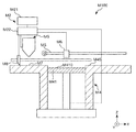
- FIG. 21 is a side view schematically showing the first embodiment of the three-dimensional structure manufacturing apparatus.
- the three-dimensional structure manufacturing apparatus M100 of this embodiment includes a nozzle that discharges a composition 2 ′ for manufacturing a three-dimensional structure, and a layer formed by discharging the composition 2 ′ for manufacturing a three-dimensional structure from the nozzle. 1 is provided with laser light irradiation means M6 for irradiating laser light L to 1, and the three-dimensional structure 10 is manufactured by stacking the layers 1.
- the three-dimensional structure manufacturing apparatus M100 of the present embodiment discharges a control part M2 and a composition (composition) 2 ′ for manufacturing a three-dimensional structure including the particles 21 in a predetermined pattern. And a laser beam irradiation means M6 for irradiating the composition 2 ′ supplied in a predetermined pattern with a laser beam L for joining the particles 21.
- the manufacturing method (particularly, the manufacturing method of the three-dimensional structure according to the first embodiment) of the present invention as described above can be suitably executed.
- the control unit M2 includes a computer M21 and a drive control unit M22.
- the computer M21 is a general desktop computer configured with a CPU, a memory, and the like inside.
- the computer M21 converts the shape of the three-dimensional structure 10 as model data, and outputs cross-sectional data (slice data) obtained by slicing the shape into parallel thin layers of slices to the drive control unit M22. .
- the drive control unit M22 included in the control unit M2 functions as a control unit that drives the composition supply unit (discharge unit) M3, the layer forming unit M4, the laser beam irradiation unit M6, and the like.
- driving of the composition supply means (discharge means) M3 (movement on the XY plane, etc.), discharge of the composition 2 ′ by the composition supply means (discharge means) M3, Z direction in FIG.
- the lowering of the movable stage (elevating stage) M41 and its lowering amount, the irradiation pattern and irradiation of the laser beam L by the laser beam irradiation means M6, the scanning speed, and the like are controlled.
- the material supply unit stores the composition 2 'described above, and is discharged from the composition supply unit (discharge unit) M3 under the control of the drive control unit M22.
- Composition supply means (discharge means) M3 can move independently in the X direction and Y direction in FIG. 12 along the guide M5.
- the layer forming unit M4 has a stage (elevating stage) M41 to which the composition 2 ′ is supplied and supports the layer 1 formed using the composition 2 ′, and a frame M45 surrounding the elevating stage M41. .
- the elevating stage M41 is sequentially lowered (moved in the negative Z-axis direction) by a predetermined amount according to a command from the drive control unit M22. To do.
- the stage M41 has a flat surface (liquid receiving surface) M410 on its upper surface (more specifically, a portion to which the composition 2 'is applied). Thereby, the layer 1 with high uniformity of thickness can be formed easily and reliably.
- the stage M41 is preferably made of a high-strength material.
- Examples of the constituent material of the stage M41 include various metal materials such as stainless steel.
- a surface treatment or a peeling structure may be applied to the plane M410 of the stage M41.
- the constituent material of the composition 2 ′ can be more effectively prevented from being firmly attached to the stage M41, the durability of the stage M41 can be improved, and the three-dimensional structure 10 can be made longer. Stable production over a period can be achieved.
- the composition supply means (discharge means) M3 is configured to move in accordance with a command from the drive control unit M22 and to discharge the composition 2 'to a desired site on the stage M41 in a predetermined pattern.
- the composition supply means (discharge means) M3 is configured to discharge the composition 2 ′.
- Examples of the composition supply unit (discharge unit) M3 include an ink jet head and various dispensers, and a dispenser is preferable.
- the highly viscous composition 2 ′ can be suitably supplied (discharged), and the sagging of the composition 2 ′ after the composition 2 ′ comes into contact with the target site is more effective. Can be prevented. As a result, the dimensional accuracy of the finally obtained three-dimensional structure 10 can be further improved. Further, by using the highly viscous composition 2 ′, the layer 1 having a relatively large thickness can be easily formed, and the productivity of the three-dimensional structure 10 can be further improved.
- the size (nozzle diameter) of the discharge portion of the composition supply means (discharge means) M3 is not particularly limited, but is preferably 10 ⁇ m or more and 100 ⁇ m or less.
- the productivity of the three-dimensional structure 10 can be further improved while further improving the dimensional accuracy of the three-dimensional structure 10.
- the composition supply means (discharge means) M3 preferably discharges the composition 2 'as droplets. Thereby, the composition 2 'can be applied in a fine pattern, and even the three-dimensional structure 10 having a fine structure can be manufactured with particularly high dimensional accuracy and particularly high productivity.
- the three-dimensional structure manufacturing apparatus M100 includes a plurality of composition supply means (discharge means) M3.
- compositions 2 ' can be used in combination. More specifically, for example, a plurality of types of compositions for forming an entity part can be used, or a composition for forming an entity part and a composition for forming a support material can be used in combination.
- the two composition supply means (discharge means) M3 the first composition supply means (first discharge means) M3A and the second composition supply means (second discharge means) Means) M3B is provided.
- compositions for forming an entity part thereby, for example, it is possible to use two kinds of compositions for forming an entity part, or one kind of composition for forming an entity part and one kind of composition for forming a support material.
- productivity of the three-dimensional structure 10 can be further improved by supplying the same type of composition 2 'from different composition supply means (discharge means) M3.
- the laser beam irradiation means M6 has a function of irradiating (scanning) the laser beam L for bonding the particles 21 contained in the composition 2 'after the composition 2' has contacted the target site.
- the particles 21 contained in the composition 2 ′ can be joined to form the joined portion 3.
- energy can be selectively applied to the composition 2 ′, and the energy efficiency of the formation of the joint 3 is further improved. be able to.
- grains 21, removal of a binder, etc. can be performed more efficiently, and the productivity of the three-dimensional structure 10 can be improved more.
- energy efficiency can be improved, it is advantageous also from an energy-saving viewpoint.
- the three-dimensional structure 10 may be manufactured in a chamber in which the composition of the atmosphere is controlled.
- the bonding step can be performed in an inert gas, and unintentional modification of particles can be more effectively prevented.
- the three-dimensional structure 10 made of a material having a composition different from the composition of the particles used as the raw material can be suitably manufactured.
- FIG. 22 is a side view schematically showing a second embodiment of the three-dimensional structure manufacturing apparatus.
- the three-dimensional structure manufacturing apparatus M100 of the present embodiment includes a composition supply means M9 that contains a composition 2 ′ for manufacturing a three-dimensional structure and a composition for manufacturing a three-dimensional structure supplied from the composition supply means M9.
- a flattening means M8 for flattening 2 ′ to form the layer 1 and a laser light irradiation means M6 for irradiating the layer 1 with the laser light L are provided, and the three-dimensional structure 10 is manufactured by stacking the layers 1 .
- the three-dimensional structure manufacturing apparatus M100 of the present embodiment is supplied from the control unit M2, the composition supply unit M9 that contains the composition 2 ′ including the particles 21, and the composition supply unit M9.
- the composition placing section (composition placing section) M7 on which the composition 2 ′ is placed (temporarily placed) and the composition 2 ′ placed on the composition placing section M7 are moved to the stage M41.
- the three-dimensional structure 10 is formed by stacking the layers 1 and the flattening means M8 for flattening and forming the layer 1 and the laser light irradiation means M6 for irradiating the layer 1 with the laser light L in a predetermined pattern. To manufacture.
- the method for manufacturing a three-dimensional structure of the present invention as described above (particularly, the method for manufacturing a three-dimensional structure according to the second embodiment) can be suitably executed.
- the drive control unit M22 included in the control unit M2 functions as a control unit that drives the composition supply unit M9, the planarization unit M8, the layer forming unit M4, the laser beam irradiation unit M6, and the like.
- the composition supply means M3 accommodates the composition (composition) 2 ′ for producing a three-dimensional structure inside, moves in accordance with a command from the drive control unit M22, and the composition 2 ′ accommodated inside the composition supply means M3 It is comprised so that it may be supplied to the object mounting part (composition temporary placement part) M7.
- the flattening means M8 is a squeegee having a longitudinal shape extending in the Y direction and having a blade having a blade-like shape with a sharp tip at the lower end.
- the length of the blade in the Y direction is equal to or greater than the width of the stage M41 (modeling region) (the length in the Y direction).
- the three-dimensional structure manufacturing apparatus M100 has a vibration mechanism (not shown) that applies minute vibrations to the blade so that the composition 2 ′ can be smoothly diffused (formation of the layer 1) by the flattening means (squeegee) M8. ) May be provided.
- the frame body M45 has a function of supporting the side surface of the layer 1 formed on the stage M41. Further, when the layer 1 is formed, it also has a function of defining the area of the layer 1.
- the frame M45 is preferably made of a high-strength material.
- Examples of the constituent material of the frame M45 include various metal materials such as stainless steel.
- the three-dimensional structure according to the present invention is manufactured using the method for manufacturing a three-dimensional structure according to the present invention as described above. Thereby, the three-dimensional structure excellent in reliability can be provided.
- the use of the three-dimensional structure is not particularly limited, and examples thereof include appreciation items and exhibits such as dolls and figures; medical devices such as implants.
- the three-dimensional structure may be applied to any of prototypes, mass-produced products, and custom-made products.
- the configuration of each part can be replaced with any structure that exhibits the same function, and any Configurations can also be added.
- the three-dimensional structure manufacturing apparatus used in the method for manufacturing a three-dimensional structure of the present invention may include a heating means for heating the composition to be discharged.
- a heating means for heating the composition to be discharged for heating the composition to be discharged.
- the viscosity of a composition can be reduced and discharge property can be improved more.
- the composition after discharge is cooled, the viscosity of the composition after discharge is increased, and the stability of the pattern shape formed by the composition is further improved. Can be made. Thereby, productivity and dimensional accuracy of a three-dimensional structure can be made compatible at a higher level.
- the three-dimensional structure manufacturing apparatus used in the method for manufacturing a three-dimensional structure of the present invention may include a cooling means (not shown).
- a cooling means (not shown).
- the layer can be rapidly cooled after the joining of the particles, and the subsequent steps can be suitably performed.
- an infrared halogen lamp, a carbon heater, or the like may be provided as a solvent removing means.
- the case where the layer is directly formed on the surface of the stage has been representatively described.
- a modeling plate is arranged on the stage, and the layer is stacked on the modeling plate to perform three-dimensional modeling. You may manufacture things.
- the modeling plate and the particles constituting the lowermost layer may be joined, and then the modeling plate may be removed from the target three-dimensional structure by post-processing. .
- the case where the second pattern formation step is performed after the first pattern formation step is mainly described for a single layer.
- the order of the first pattern forming step and the second pattern forming step may be reversed.
- the case where the solvent removal step is performed after the first pattern formation step and the second pattern formation step are typically described for a single layer. You may perform a solvent removal process separately about each after the 1st pattern formation process and the 2nd pattern formation process.
- a stacked body in which a plurality of layers are stacked is, for example, A layer that does not have the first pattern or a layer that does not have the second pattern may be provided.
- a layer in which a portion corresponding to the substantial part is not formed may be formed on the contact surface with the stage (immediately above the stage), and the layer may function as a sacrificial layer. Good.
- the order of the steps and processes is not limited to those described above, and at least a part of them may be exchanged.
- first joining step and the second joining step may be interchanged, and the first joining step and the second joining step may be performed simultaneously at different parts of the layer. .
- the joining step the case where the particles contained in the composition for forming a support part are not joined together with the joining of particles contained in the composition for forming a substantial part is mainly performed.
- the support portion may not be formed.
- you may perform a pre-processing process, an intermediate processing process, and a post-processing process as needed.
- Examples of the pretreatment process include a stage cleaning process.
- Examples of the post-processing step include a cleaning step, a shape adjustment step for performing deburring, a coloring step, a coating layer forming step, a heat treatment step for improving the bonding strength of particles, and the like.
- the manufacturing method of the three-dimensional structure according to the present invention is not limited to the one executed using the three-dimensional structure manufacturing apparatus as described above.
- Example A1 Manufacture of a composition for manufacturing a three-dimensional structure By mixing 30 parts by volume of SUS316L powder having an average particle size of 10 ⁇ m and 70 parts by volume of glycerin as a solvent, a composition for manufacturing a three-dimensional structure As a result, a composition for forming a substantial part was obtained (see Table 1).
- a composition for forming a support part as a composition for producing a three-dimensional structure was obtained.
- composition set for manufacturing a three-dimensional structure which was composed of the composition for forming the substantial part and the composition for forming the support part.
- the design dimension is a rectangular parallelepiped shape having a thickness: 4 mm ⁇ width: 10 mm ⁇ length: 80 mm.
- a three-dimensional structure was manufactured as follows.
- a three-dimensional structure manufacturing apparatus as shown in FIG. 21 is prepared, and a support portion forming composition is formed in a predetermined pattern on a stage from a nozzle of a dispenser as a first composition supply means.
- a first pattern (support portion pattern) was formed by discharging as a droplet (layer forming step (first pattern forming step)).
- a second pattern is formed by ejecting the composition for forming the substantial part as a plurality of droplets in a predetermined pattern on the stage from a nozzle of a dispenser as a second composition supply unit. (Layer forming step (second pattern forming step)).
- the layer thickness was 26 ⁇ m.
- the layer comprising the first pattern and the second pattern was subjected to a heat treatment at 250 ° C. to remove the solvent contained in the layer (solvent removal step).
- the first pattern and the second pattern of the layer are sequentially scanned (irradiated) with laser light (YAG laser, maximum peak wavelength: 1064 nm, laser output: 110 W, beam diameter: 100 ⁇ m) to bond the particles. went. Thereby, the 1st junction part (support part) and the 2nd junction part (substance part) were formed (joining process).
- the laser beam scanning speed was 400 mm / second.
- Examples A2 to A4 The structure of the composition for forming an entity part and the thickness of the layer formed in the layer forming step are as shown in Table 1, and the three-dimensional modeling is performed in the same manner as in Example A1 except that the irradiation condition of the laser beam is adjusted.
- a composition for manufacturing objects composition set for manufacturing a three-dimensional structure
- a three-dimensional structure were manufactured.
- compositions for forming an entity part and the thickness of the layer formed in the layer forming step are as shown in Table 1, and the three-dimensional modeling is performed in the same manner as in Example A1 except that the irradiation condition of the laser beam is adjusted.
- a composition for manufacturing objects (composition set for manufacturing a three-dimensional structure) and a three-dimensional structure were manufactured.
- Table 1 summarizes the configurations of the compositions for manufacturing a three-dimensional structure (composition for forming an entity part) of each of the above Examples and Comparative Examples.
- glycerin is indicated by “Gly”.
- a layer obtained by performing a layer formation step, a solvent removal step, and a joining step under the same conditions as the manufacturing conditions of the three-dimensional structure in each of the examples and the comparative examples.
- the arithmetic average height Sa, maximum height Sz, skewness bias degree Ssk, and kurtosis kurtosis degree Sku specified by ISO 25178 were determined for the surface of the layer (region corresponding to the substantial part). These values obtained for the area corresponding to the substantial part are summarized in Table 1. From the values of Ssk and Sku, it can be seen that when D S / D 50 > 5.0, the surface roughness distribution of the modeling surface tends to change to a sharp and uneven distribution.
- the viscosities of the composition for forming a support part and the composition for forming a substantial part used in each of the above examples were values within a range of 1000 mPa ⁇ s to 20000 mPa ⁇ s.
- the volume per droplet of the composition for forming a support portion and the composition for forming a substantial portion in each of the above Examples and Comparative Examples was a value in the range of 1 nL to 50 nL.
- the solvent content in the layer after the solvent removal step was a value in the range of 0.5% by mass or more and 20% by mass or less.
- grains contained in the composition for support part formation used in the said each Example and the composition for solid part formation were all values in the range of 0.2 micrometer or more and 80 micrometers or less.
- the deviation from the design value for the largest deviation from the design value is 4.0% or more and less than 7.0%.
- E The deviation from the design value for the largest deviation from the design value among the thickness, width, and length is 7.0% or more.
- the present invention was able to produce a highly reliable three-dimensional structure with excellent dimensional accuracy and strength.
- the comparative example a satisfactory result was not obtained.
- Example B1 [4] Preparation of composition for manufacturing a three-dimensional structure
- the composition for forming a solid part manufactured in Example A1 was prepared as a composition for manufacturing a three-dimensional structure.
- the design dimension is a rectangular parallelepiped shape having a thickness: 4 mm ⁇ width: 10 mm ⁇ length: 80 mm.
- a three-dimensional structure was manufactured as follows.
- a three-dimensional structure manufacturing apparatus as shown in FIG. 22 was prepared, and the three-dimensional structure manufacturing apparatus was supplied from the composition supply means to the composition placement section (composition temporary storage section).
- the composition placement section composition temporary storage section
- the three-dimensional structure manufacturing product supplied to the composition placement portion is moved to the stage M41 and flattened to form a layer ( Layer forming step).
- the thickness of the formed layer was 26 ⁇ m.
- the formed layer was subjected to a heat treatment at 250 ° C. to remove the solvent contained in the layer (solvent removal step).
- the layer is scanned (irradiated) with a laser beam (YAG laser, maximum peak wavelength: 1064 nm, laser output: 110 W, beam diameter: 100 ⁇ m) in a pattern corresponding to the substantial part of the three-dimensional structure to be formed.
- the particles were bonded to form a bonded portion (substance portion) (bonding step).
- the laser beam scanning speed was set to 400 mm / second.
- a layered product having a shape corresponding to the three-dimensional structure to be manufactured was obtained by repeatedly performing a series of steps including the layer forming step or the joining step as described above.
- Examples B2 to B4 The composition for forming an entity part manufactured in Examples A2 to A4 was prepared as a composition for manufacturing a three-dimensional structure in Examples B2 to B4, respectively.
- the three-dimensional structure was manufactured in the same manner as in Example B1 except that the thickness of the layer formed in the layer forming step was as shown in Table 3 and the laser light irradiation conditions were adjusted.
- Comparative Examples B1 to B7 The composition for forming a substantial part produced in Comparative Examples A1 to A7 was prepared as a composition for producing a three-dimensional structure of Comparative Examples B1 to B7, respectively.
- the three-dimensional structure was manufactured in the same manner as in Example B1 except that the thickness of the layer formed in the layer forming step was as shown in Table 3 and the laser light irradiation conditions were adjusted.
- Table 3 summarizes the composition of the composition for producing a three-dimensional structure of each of the above Examples and Comparative Examples.
- glycerin is indicated by “Gly”.
- a layer (single layer that is not laminated) obtained by performing a layer formation step, a solvent removal step, and a joining step under the same conditions as the manufacturing conditions of the three-dimensional structure in each of the examples and the comparative examples.
- the arithmetic average height Sa, the maximum height Sz, the skewness bias degree Ssk, and the kurtosis sharpness degree Sku defined by ISO 25178 were determined for the surface of the layer (region corresponding to the substantial part).
- the solvent content in the layer after the solvent removal step was a value within the range of 0.5% by mass or more and 20% by mass or less.
- grains contained in the composition for three-dimensional structure manufacture used in each said Example was a value within the range of 0.2 micrometer or more and 80 micrometers or less.
- the deviation from the design value for the largest deviation from the design value is 4.0% or more and less than 7.0%.
- E The deviation from the design value for the largest deviation from the design value among the thickness, width, and length is 7.0% or more.
- SYMBOLS 10 Three-dimensional structure, 1 ... Layer, 2 '... Composition (Composition for three-dimensional structure manufacture), 2A' ... Composition (Composition for support part formation), 2B '... Composition (Substantial part formation) Composition), 21 ... particle (dispersoid), 21A ... particle (dispersoid), 21B ... particle (dispersoid), 2A ... first pattern (support part pattern), 2B ... second pattern (substance) Part pattern), 3 ... joining part, 3A ... joining part (first joining part), 3B ... joining part (second joining part), 4 ... substantive part, 5 ...
- M100 Three-dimensional structure manufacturing apparatus
- M2 Control unit
- M21 Computer
- M22 Drive control unit
- M3 Composition supply means (discharge means)
- M3A First composition supply means (first discharge) Means)
- M3B Second composition supply means (second discharge means)
- M41 Stage (elevating stage)
- M410 Flat surface (liquid receiving surface)
- M45 ... Frame body
- M5 ... Guide
- M6 Laser light irradiation means
- M7 Composition placement section (composition temporary placement section)
- M8 Flattening means
- M9 composition supplying means, L ... laser light
Landscapes
- Chemical & Material Sciences (AREA)
- Engineering & Computer Science (AREA)
- Materials Engineering (AREA)
- Manufacturing & Machinery (AREA)
- Physics & Mathematics (AREA)
- Optics & Photonics (AREA)
- Mechanical Engineering (AREA)
- Chemical Kinetics & Catalysis (AREA)
- Life Sciences & Earth Sciences (AREA)
- Wood Science & Technology (AREA)
- Organic Chemistry (AREA)
- Plasma & Fusion (AREA)
- General Chemical & Material Sciences (AREA)
- Ceramic Engineering (AREA)
- Powder Metallurgy (AREA)
- Producing Shaped Articles From Materials (AREA)
Abstract
The purpose of the present invention is to provide a three-dimensional object production method capable of producing a highly reliable three-dimensional object. The present invention provides a three-dimensional object production method for laminating a plurality of layers to produce a three-dimensional object, characterized in that the method involves a repetition of a series of steps including a layer formation step for forming a layer using a composition containing a plurality of particles and a joining step for joining the particles contained in the layers by irradiating the layer with laser light, the relation of Ds/D50 < 5.0 is satisfied where D50 [μm] is the average particle size of the particles and Ds [μm] is the thickness of the layer formed in the layer formation step, and the arithmetic mean surface height Sa of the layer in a state in which the particles are joined in the joining step is 15 μm or less.
Description
本発明は、三次元造形物の製造方法に関する。
The present invention relates to a method for manufacturing a three-dimensional structure.
従来より、複数個の粒子を含む組成物を用いた三次元造形物の製造が行われてきている。特に、近年、三次元物体のモデルデータを多数の二次元断面層データ(スライスデータ)に分割した後、各二次元断面層データに対応する断面部材(層)を順次造形しつつ、断面部材を順次積層することによって三次元造形物を形成する積層法(三次元造形法)が注目されている。
Conventionally, a three-dimensional structure using a composition containing a plurality of particles has been manufactured. In particular, in recent years, after the model data of a three-dimensional object is divided into a number of two-dimensional cross-sectional layer data (slice data), the cross-sectional member (layer) corresponding to each two-dimensional cross-sectional layer data is sequentially formed, A laminating method (three-dimensional modeling method) that forms a three-dimensional structure by sequentially laminating is attracting attention.
積層法は、造形しようとする三次元造形物のモデルデータさえあれば、直ちに形成することが可能であり、造形に先立って金型を作成する等の必要がないので、迅速にしかも安価に三次元造形物を形成することが可能である。また、薄い板状の断面部材を一層ずつ積層して形成するので、例えば内部構造を有する複雑な物体であっても、複数の部品に分けることなく一体の造形物として形成することが可能である。
The lamination method can be formed immediately as long as there is model data of the 3D model to be modeled, and there is no need to create a mold prior to modeling. It is possible to form an original model. In addition, since thin plate-like cross-sectional members are laminated one by one, for example, even a complex object having an internal structure can be formed as an integrated shaped object without being divided into a plurality of parts. .
三次元造形物の製造方法としては、粉末をスキージで層形成し当該層にレーザー光を照射して粒子同士を接合する方法や、粒子と、粒子を分散させる溶剤とを含む組成物を用いて層を形成した後に、当該層にレーザー光を照射し、粒子同士を接合する方法がある(例えば、特許文献1参照)。
As a method for producing a three-dimensional structure, a method is used in which powder is layered with a squeegee and the layer is irradiated with laser light to join the particles, or a composition containing the particles and a solvent for dispersing the particles. There is a method in which after forming a layer, the layer is irradiated with laser light to join particles together (see, for example, Patent Document 1).
このような方法では、レーザー光を照射する際に、粒子やその溶融物が飛散してしまったり、三次元造形物の内部に空隙(空孔、鬆)が形成されてしまうことにより、最終的に得られる三次元造形物の寸法精度が低下したり、三次元造形物の強度が低下すること等により、三次元造形物の信頼性が低下するという問題があった。
In such a method, when the laser beam is irradiated, particles or a melt thereof are scattered, or voids (holes, voids) are formed inside the three-dimensional structure. There has been a problem that the reliability of the three-dimensional structure is lowered due to a decrease in the dimensional accuracy of the three-dimensional structure obtained or the strength of the three-dimensional structure.
本発明の目的は、信頼性に優れた三次元造形物を製造することができる三次元造形物の製造方法を提供することにある。
An object of the present invention is to provide a manufacturing method of a three-dimensional structure that can manufacture a three-dimensional structure excellent in reliability.
このような目的は、下記の本発明により達成される。
本発明の三次元造形物の製造方法は、複数の層を積層して三次元造形物を製造する方法であって、
複数個の粒子を含む組成物を用いて前記層を形成する層形成工程と、前記層にレーザー光を照射し、前記層中に含まれる前記粒子同士を接合する接合工程とを含む一連の工程を繰り返し行い、
前記粒子の平均粒径をD50[μm]、前記層形成工程で形成された前記層の厚さをDS[μm]としたとき、DS/D50<5.0の関係を満たし、
前記接合工程により前記粒子同士が接合された状態の前記層の表面の算術平均高さSaが15μm以下であることを特徴とする。 Such an object is achieved by the present invention described below.
The manufacturing method of the three-dimensional structure of the present invention is a method of manufacturing a three-dimensional structure by laminating a plurality of layers,
A series of steps including a layer forming step of forming the layer using a composition including a plurality of particles, and a bonding step of irradiating the layer with laser light and bonding the particles contained in the layer. Repeatedly
When the average particle diameter of the particles is D 50 [μm] and the thickness of the layer formed in the layer forming step is D S [μm], the relationship of D S / D 50 <5.0 is satisfied,
The arithmetic average height Sa of the surface of the layer in a state where the particles are bonded by the bonding step is 15 μm or less.
これにより、信頼性に優れた三次元造形物を製造することができる三次元造形物の製造方法を提供することができる。
Thereby, it is possible to provide a manufacturing method of a three-dimensional structure that can manufacture a three-dimensional structure excellent in reliability.
本発明の三次元造形物の製造方法では、前記接合工程により前記粒子同士が接合された状態の前記層の表面の最大高さSzが250μm以下であることが好ましい。
これにより、三次元造形物の寸法精度をさらに向上させることができる。 In the three-dimensional structure manufacturing method of the present invention, it is preferable that the maximum height Sz of the surface of the layer in a state where the particles are bonded by the bonding step is 250 μm or less.
Thereby, the dimensional accuracy of the three-dimensional structure can be further improved.
本発明の三次元造形物の製造方法では、前記組成物を吐出して前記層を形成することが好ましい。
In the method for producing a three-dimensional structure of the present invention, it is preferable to form the layer by discharging the composition.
これにより、製造すべき三次元造形物の断面形状等に対応するパターンで、三次元造形物形成用組成物を付与することができ、より微細な構造を有する三次元造形物も好適に製造することができる。また、三次元造形物形成用組成物の無駄を抑制することができ、また、三次元造形物の製造に利用されなかった三次元造形物形成用組成物等の回収を省略または簡略化することができる。
Accordingly, the composition for forming a three-dimensional structure can be applied in a pattern corresponding to the cross-sectional shape of the three-dimensional structure to be manufactured, and a three-dimensional structure having a finer structure is also preferably manufactured. be able to. Further, waste of the composition for forming a three-dimensional structure can be suppressed, and recovery of the composition for forming a three-dimensional structure that was not used for manufacturing the three-dimensional structure is omitted or simplified. Can do.
本発明の三次元造形物の製造方法では、前記組成物を平坦化手段により平坦化して前記層を形成することが好ましい。
In the method for producing a three-dimensional structure of the present invention, it is preferable that the composition is flattened by a flattening means to form the layer.
これにより、接合部が設けられた層を形成するための走査処理の回数を減らすことができ、三次元造形物の生産性をより向上させることができる。また、単一種の組成物(三次元造形物製造用組成物)を用いた場合でも、複雑な形状の三次元造形物であっても好適に製造することができる。また、単一種の三次元造形物製造用組成物を用いることにより、接合部の形成に利用されなかった三次元造形物製造用組成物(粒子)を容易に回収し、再利用に供することができる。
This makes it possible to reduce the number of scanning processes for forming the layer provided with the joint, and to further improve the productivity of the three-dimensional structure. Moreover, even when a single kind of composition (composition for producing a three-dimensional structure) is used, even a three-dimensional structure having a complicated shape can be suitably produced. In addition, by using a single type of three-dimensional structure manufacturing composition, the three-dimensional structure manufacturing composition (particles) that has not been used for forming the joint can be easily collected and reused. it can.
本発明の三次元造形物の製造方法では、前記層形成工程で形成された前記層の厚さDSが、5μm以上300μm以下であることが好ましい。
In the manufacturing method of the 3D object of the present invention, the thickness D S of the layer forming step the layer formed by is preferably at 5μm or 300μm or less.
これにより、三次元造形物の生産性を向上させつつ、三次元造形物の信頼性(特に、寸法精度、強度等)をより向上させることができる。
This makes it possible to further improve the reliability (particularly, dimensional accuracy, strength, etc.) of the three-dimensional structure while improving the productivity of the three-dimensional structure.
本発明の三次元造形物の製造方法では、前記粒子の平均粒径D50が、0.1μm以上50μm未満であることが好ましい。
In the manufacturing method of the 3D object of the present invention, the average particle diameter D 50 of the particles is preferably less than or 0.1 [mu] m 50 [mu] m.
これにより、三次元造形物の生産性をより向上させつつ、三次元造形物の信頼性をより向上させることができる。
Thereby, it is possible to further improve the reliability of the three-dimensional structure while improving the productivity of the three-dimensional structure.
以下、添付する図面を参照しつつ、好適な実施形態について詳細な説明をする。
《三次元造形物の製造方法》
まず、本発明の三次元造形物の製造方法について説明する。 Hereinafter, preferred embodiments will be described in detail with reference to the accompanying drawings.
<Method for producing three-dimensional structure>
First, the manufacturing method of the three-dimensional structure according to the present invention will be described.
<第1実施形態>
図1~図10は、本発明の第1実施形態の三次元造形物の製造方法の工程を模式的に示す縦断面図である。図11は、本発明の第1実施形態の三次元造形物の製造方法を示すフローチャートである。 <First Embodiment>
1 to 10 are longitudinal sectional views schematically showing the steps of the method for manufacturing a three-dimensional structure according to the first embodiment of the present invention. FIG. 11 is a flowchart showing a method for manufacturing a three-dimensional structure according to the first embodiment of the present invention.
本実施形態の三次元造形物10の製造方法は、複数の層1を積層して三次元造形物10を製造する方法であって、複数個の粒子21を含む三次元造形物製造用組成物(組成物)2’を用いて層1を形成する層形成工程(図1、図2、図5、図6参照)と、層1にレーザー光Lを照射し、層1中に含まれる粒子21同士を接合する接合工程(図3、図4、図7、図8参照)とを含む一連の工程を繰り返し行う(図9参照)。
The manufacturing method of the three-dimensional structure 10 of this embodiment is a method of manufacturing the three-dimensional structure 10 by laminating a plurality of layers 1, and includes a plurality of particles 21. (Composition) Layer formation step (see FIGS. 1, 2, 5, and 6) for forming the layer 1 using 2 ′, and particles contained in the layer 1 by irradiating the layer 1 with the laser beam L A series of steps including a joining step (see FIGS. 3, 4, 7, and 8) for joining 21 to each other is repeated (see FIG. 9).
そして、粒子21の平均粒径をD50[μm]、層形成工程で形成された層1の厚さをDS[μm]としたとき、DS/D50<5.0の関係を満たし、接合工程により粒子21同士が接合された状態の層1の表面の算術平均高さSa(ISO 25178)が15μm以下である。
When the average particle diameter of the particles 21 is D 50 [μm] and the thickness of the layer 1 formed in the layer forming step is D S [μm], the relationship of D S / D 50 <5.0 is satisfied. The arithmetic average height Sa (ISO 25178) of the surface of the layer 1 in a state where the particles 21 are bonded to each other by the bonding step is 15 μm or less.
これにより、粒子21やその溶融物(以下、単に「粒子21等」ともいう)が飛散してしまったり、三次元造形物10の内部に空隙(空孔、鬆)が形成されてしまうことにより、三次元造形物10の寸法精度が低下したり、三次元造形物10の強度が低下すること等を効果的に防止することができ、信頼性に優れた三次元造形物10を製造することができる三次元造形物10の製造方法を提供することができる。
As a result, particles 21 or a melt thereof (hereinafter also simply referred to as “particles 21 or the like”) is scattered or voids (holes or voids) are formed inside the three-dimensional structure 10. It is possible to effectively prevent a reduction in the dimensional accuracy of the three-dimensional structure 10 or a decrease in the strength of the three-dimensional structure 10, and to manufacture the three-dimensional structure 10 having excellent reliability. The manufacturing method of the three-dimensional structure 10 which can be provided can be provided.
より具体的には、従来においては、複数個の粒子を含む層にレーザー光を照射すると、そのエネルギーにより、当該粒子が層の当初の位置からはじき出されたり、当該粒子の溶融物の液溜り(溶融プール)が波打ち、レーザー光の走査等に伴い、当該溶融物がはじき出されることがあり、これにより、レーザー光照射後の層の表面の不本意な凹凸が発生し、最終的に得られる三次元造形物の寸法精度が低くなるという問題があった。また、はじき出された粒子等が層の他の部位に付着すること等により、三次元造形物の内部に空隙(空孔、鬆)が形成され、三次元造形物の強度が低下するという問題があった。以上のようなことから、三次元造形物の信頼性は、低いものであった。これに対し、本発明では、粒子の平均粒径D50と、層形成工程で形成された層の厚さDSとで所定の関係(DS/D50<5.0)を満足するとともに、接合工程により形成された層(接合工程により粒子同士が接合された状態の層)の表面の算術平均高さSaが所定値以下(15μm以下)であることにより、上記のような問題の発生を防止することができる点に特徴を有する。なお、上記のような接合工程により形成された層の表面の算術平均高さSaについての条件は、少なくとも、製造すべき三次元造形物の実体部に対応する領域において満足していればよい。例えば、本実施形態のように、サポート部5を形成する場合には、サポート部5に対応する領域では、上記のような算術平均高さSaについての条件を満足していなくてもよいが、実体部4に対応する領域およびサポート部5に対応する領域の両方において、上記のような算術平均高さSaについての条件を満足しているのが好ましい。これにより、前述したような効果がより顕著に発揮される。
More specifically, conventionally, when a layer including a plurality of particles is irradiated with laser light, the energy causes the particles to be ejected from the initial position of the layer or a liquid pool of the particles ( As the molten pool) undulates and the laser beam is scanned, the melt may be ejected, causing unintended irregularities on the surface of the layer after laser beam irradiation, and finally obtaining the tertiary There was a problem that the dimensional accuracy of the original model was lowered. In addition, there is a problem that voids (holes, voids) are formed inside the three-dimensional structure due to adhesion of the ejected particles or the like to other parts of the layer, and the strength of the three-dimensional structure decreases. there were. As described above, the reliability of the three-dimensional structure is low. On the other hand, in the present invention, the average particle diameter D 50 of the particles and the thickness D S of the layer formed in the layer forming step satisfy a predetermined relationship (D S / D 50 <5.0). When the arithmetic average height Sa of the surface of the layer formed by the joining process (the layer in which particles are joined by the joining process) is not more than a predetermined value (15 μm or less), the above-described problem occurs. It is characterized in that it can be prevented. In addition, the conditions regarding the arithmetic average height Sa of the surface of the layer formed by the above joining processes should just be satisfied at least in the region corresponding to the substantial part of the three-dimensional structure to be manufactured. For example, when the support portion 5 is formed as in the present embodiment, the region corresponding to the support portion 5 may not satisfy the condition for the arithmetic average height Sa as described above. It is preferable that both the area corresponding to the entity part 4 and the area corresponding to the support part 5 satisfy the condition regarding the arithmetic average height Sa as described above. Thereby, the effects as described above are more remarkably exhibited.
本発明において、平均粒径とは、体積基準の平均粒径を言い、例えば、サンプルをメタノールに添加し、超音波分散器で3分間分散した分散液をコールターカウンター法粒度分布測定器(COULTER ELECTRONICS INS製TA-II型)にて、50μmのアパチャーを用いて測定することにより求めることができる。
In the present invention, the average particle diameter means a volume-based average particle diameter. For example, a dispersion obtained by adding a sample to methanol and dispersing for 3 minutes with an ultrasonic disperser is used as a Coulter counter particle size distribution analyzer (COULTER ELECTRONICS). It can be determined by measuring with a 50 μm aperture using an INS TA-II type).
これに対し、前述した条件を満足しない場合には、上記のような優れた効果は得られない。
On the other hand, if the above-mentioned conditions are not satisfied, the above excellent effects cannot be obtained.
例えば、粒子の平均粒径D50に対する層の厚さDSの比率(DS/D50)が大きすぎると、レーザー光を照射した際の粒子等の飛散や、三次元造形物の内部における空隙(空孔、鬆)が生じやすくなる。特に、DSが大きい値であることによりDS/D50の値が大きい場合には、厚さ方向(高さ方向)において、層の厚さより精密な三次元造形物の製造が困難となり、その結果として、三次元造形物の寸法精度が低下する。また、D50が小さい値であることによりDS/D50の値が大きい場合には、上記のようなレーザー光を照射した際の粒子等の飛散や、三次元造形物の内部における空隙(空孔、鬆)の発生がより顕著になる。また、三次元造形物製造用組成物の流動性が低下し、三次元造形物製造用組成物の取り扱いのしやすさが低下するとともに、三次元造形物の生産性が低下する。また、D50の値が特に小さい場合には、三次元造形物製造用組成物中における粒子の凝集を生じやすくなり、レーザー光照射前の段階において、層の表面の不本意な凹凸が生じやすくなる。その結果、レーザー光を照射した際の粒子等の飛散等による影響と相まって、三次元造形物の寸法精度は特に低くなる。
For example, if the ratio of the layer thickness D S to the average particle diameter D 50 of the particles (D S / D 50 ) is too large, scattering of particles or the like when irradiated with laser light, or the inside of the three-dimensional structure Air gaps (holes, voids) are likely to occur. In particular, when the value of D S / D 50 by D S is a large value is large, in the thickness direction (height direction), it is difficult to produce a precise three-dimensional shaped object than the thickness of the layer, As a result, the dimensional accuracy of the three-dimensional structure decreases. Further, if the value of D S / D 50 by D 50 is smaller is high, scattering and particle like when irradiated with laser light as described above, voids in the interior of the three-dimensional model ( The generation of vacancies and voids becomes more prominent. Moreover, while the fluidity | liquidity of the composition for three-dimensional structure manufacture falls, the ease of handling of the composition for three-dimensional structure manufacture falls, and the productivity of a three-dimensional structure falls. Further, when the value of D 50 is particularly small, tends to occur agglomeration of the particles in the 3D object for producing a composition, in a stage before the laser irradiation, it tends to occur undesirable unevenness of the surface of the layer Become. As a result, the dimensional accuracy of the three-dimensional structure is particularly low, coupled with the influence of scattering of particles and the like when irradiated with laser light.
また、接合工程により粒子同士が接合された状態の層の表面の算術平均高さSaが大きすぎると、層の表面に存在する凹凸が当該層の上面に形成される層の形状にも大きな影響を与え、最終的に得られる三次元造形物の寸法精度が低下する。
Also, if the arithmetic average height Sa of the surface of the layer in a state where the particles are bonded by the bonding process is too large, the unevenness existing on the surface of the layer has a large effect on the shape of the layer formed on the upper surface of the layer. The dimensional accuracy of the finally obtained three-dimensional structure decreases.
前述したように、粒子21の平均粒径をD50[μm]、層形成工程で形成された層1の厚さをDS[μm]としたとき、DS/D50<5.0の関係を満足すればよいが、1.0<DS/D50<4.0の関係を満足するのが好ましく、1.2<DS/D50<3.5の関係を満足するのがより好ましく、1.4<DS/D50<3.0の関係を満足するのがさらに好ましい。これにより、前述したような効果はより顕著に発揮される。
As described above, when the average particle diameter of the particles 21 is D 50 [μm] and the thickness of the layer 1 formed in the layer forming step is D S [μm], D S / D 50 <5.0. The relationship may be satisfied, but it is preferable that the relationship of 1.0 <D S / D 50 <4.0 is satisfied, and the relationship of 1.2 <D S / D 50 <3.5 is satisfied. More preferably, it is more preferable that the relationship of 1.4 <D S / D 50 <3.0 is satisfied. Thereby, the effects as described above are more remarkably exhibited.
また、接合工程により粒子21同士が接合された状態の層1の表面の算術平均高さSaは、15μm以下であればよいが、11μm以下であるのが好ましく、8.0μm以下であるのがより好ましく、0μm超5.0μm以下であるのがさらに好ましい。これにより、前述したような効果はより顕著に発揮される。
In addition, the arithmetic average height Sa of the surface of the layer 1 in a state where the particles 21 are bonded to each other by the bonding process may be 15 μm or less, preferably 11 μm or less, and preferably 8.0 μm or less. More preferably, it is more than 0 μm and 5.0 μm or less. Thereby, the effects as described above are more remarkably exhibited.
接合工程が施された層1の表面状態(算術平均高さSa等)を決定する要因としては、種々挙げられるが、三次元造形物製造用組成物2’の構成(より具体的には、例えば、粒子21の構成材料、粒径、粒度分布等)、層形成工程で形成される層1の厚さ、レーザー光Lの照射条件(例えば、レーザー光Lの種類、レーザー光Lのビーム径、走査速度、レーザー出力等)が挙げられる。
There are various factors that determine the surface state (arithmetic average height Sa, etc.) of the layer 1 subjected to the joining step, but the configuration of the composition 2 ′ for manufacturing a three-dimensional structure (more specifically, For example, the constituent material of the particles 21, the particle size, the particle size distribution, etc., the thickness of the layer 1 formed in the layer forming step, the irradiation conditions of the laser light L (for example, the type of the laser light L, the beam diameter of the laser light L) Scanning speed, laser output, etc.).
また、本実施形態では、三次元造形物製造用組成物2’として、粒子21に加え、粒子21を分散させる分散媒として機能する溶剤を含むものを用い、かつ、層形成工程および接合工程を含む一連の工程中において、層形成工程と接合工程との間に溶剤除去工程を有している。これにより、三次元造形物製造用組成物2’の流動性を良好なものとし、三次元造形物製造用組成物2’の取り扱いのし易さ、層1の形成の容易性を向上させることができる。また、形成される層1の平坦性をより良好なものとすることができる。
Moreover, in this embodiment, what contains the solvent which functions as a dispersion medium which disperse | distributes the particle | grains 21 in addition to the particle | grains 21 as composition 3 'for three-dimensional structure manufacture, and a layer formation process and a joining process are used. In a series of processes including, a solvent removal process is provided between the layer formation process and the bonding process. Thereby, fluidity | liquidity of composition 2 'for three-dimensional structure manufacture is made favorable, and the ease of handling of composition 2' for three-dimensional structure manufacture and the ease of formation of layer 1 are improved. Can do. Further, the flatness of the formed layer 1 can be made better.
なお、本明細書において、溶剤とは、粒子を分散することができる液体(分散媒)であり、揮発性の液体のことをいう。
In addition, in this specification, a solvent is a liquid (dispersion medium) which can disperse | distribute particle | grains, and means a volatile liquid.
以下、各工程について詳細に説明する。
[層形成工程] Hereinafter, each step will be described in detail.
[Layer formation process]
[層形成工程] Hereinafter, each step will be described in detail.
[Layer formation process]
本実施形態では、三次元造形物製造用組成物2’を吐出して層1を形成する。言い換えると、本実施形態では、吐出法により、層1を形成する。
In this embodiment, the layer 1 is formed by discharging the composition 2 ′ for manufacturing a three-dimensional structure. In other words, in this embodiment, the layer 1 is formed by a discharge method.
これにより、製造すべき三次元造形物10の断面形状等に対応するパターンで、三次元造形物製造用組成物2’を付与することができ、より微細な構造を有する三次元造形物10も好適に製造することができる。また、製造すべき三次元造形物10の断面積に応じて各層1における三次元造形物製造用組成物2’の付与量を好適に調整することができ、三次元造形物製造用組成物2’の使用量を抑制することができる。その結果、三次元造形物製造用組成物2’の無駄を抑制することができ、また、三次元造形物10の製造に利用されなかった三次元造形物製造用組成物2’等の回収を省略または簡略化することができる。このような効果は、製造すべき三次元造形物10の断面積がステージM41の面積に比して、特に小さい場合(例えば、製造すべき三次元造形物10の断面積がステージM41の面積の10分の1以下の場合等)に、より顕著に発揮される。
Thereby, 3D modeling composition 2 'can be provided with the pattern corresponding to the cross-sectional shape etc. of the three-dimensional modeling thing 10 which should be manufactured, and the three-dimensional modeling object 10 which has a finer structure also. It can manufacture suitably. Moreover, according to the cross-sectional area of the three-dimensional structure 10 to be manufactured, the application amount of the composition 2 ′ for manufacturing a three-dimensional structure in each layer 1 can be suitably adjusted, and the composition 2 for manufacturing a three-dimensional structure 2 The amount of use can be suppressed. As a result, waste of the composition 2 ′ for manufacturing the three-dimensional structure can be suppressed, and the recovery of the composition 2 ′ for manufacturing the three-dimensional structure 2 ′ that has not been used for manufacturing the three-dimensional structure 10 can be performed. It can be omitted or simplified. Such an effect is obtained when the cross-sectional area of the three-dimensional structure 10 to be manufactured is particularly small compared to the area of the stage M41 (for example, the cross-sectional area of the three-dimensional structure 10 to be manufactured is equal to the area of the stage M41). In the case of 1/10 or less, etc.).
なお、本明細書において、吐出法とは、組成物(三次元造形物製造用組成物)を所定のパターンで吐出して層に対応するパターンを形成する方法のことを言い、供給された組成物をスキージ、ローラー等により平坦化して層を形成する方法(後述する第2実施形態の方法)等とは区別される。
In this specification, the discharge method refers to a method of forming a pattern corresponding to a layer by discharging a composition (a composition for producing a three-dimensional structure) in a predetermined pattern, and a supplied composition. It is distinguished from a method of forming a layer by flattening an object with a squeegee, a roller or the like (method of a second embodiment described later).
また、本実施形態の製造方法では、層形成工程は、三次元造形物製造用組成物2’として、三次元造形物10の実体部4の形成に用いる実体部形成用組成物2B’(粒子(分散質)21Bを含む組成物)、および、実体部4となるべき部位を支持するサポート部(支持部、サポート材)5の形成に用いるサポート部形成用組成物2A’(粒子(分散質)21Aを含む組成物)を用いて行う。そして、サポート部形成用組成物(組成物)2A’を吐出して第1のパターン(サポート部用パターン)2Aを形成する第1のパターン形成工程(サポート部用パターン形成工程)と、実体部形成用組成物(組成物)2B’を吐出して第2のパターン(実体部用パターン)2Bを形成する第2のパターン形成工程(実体部用パターン形成工程)とを有している。
Moreover, in the manufacturing method of this embodiment, a layer formation process is composition 2B '(particulate formation composition 2B' (particle | grains) used for formation of the solid part 4 of the three-dimensional structure 10 as composition 2 'for three-dimensional structure manufacture. (Composition containing dispersoid) 21B) and support portion forming composition 2A ′ (particle (dispersoid) used for forming the support portion (support portion, support material) 5 that supports the portion to be the substantial portion 4) ) A composition containing 21A). Then, a first pattern forming step (support portion pattern forming step) in which a support portion forming composition (composition) 2A ′ is discharged to form a first pattern (support portion pattern) 2A; A second pattern forming step (substantive portion pattern forming step) for discharging the forming composition (composition) 2B ′ to form a second pattern (substance portion pattern) 2B.
このように、三次元造形物10の実体部4に対応する部位だけでなく、サポート部5も形成することにより、実体部4に対応する部位の不本意な変形をより効果的に防止することができ、三次元造形物10の寸法精度をより向上させることができる。また、より複雑な形状の三次元造形物10であっても好適に製造することができる。
Thus, by forming not only the part corresponding to the entity part 4 of the three-dimensional structure 10 but also the support part 5, it is possible to more effectively prevent unintentional deformation of the part corresponding to the entity part 4. Thus, the dimensional accuracy of the three-dimensional structure 10 can be further improved. Moreover, even the three-dimensional structure 10 having a more complicated shape can be suitably manufactured.
そして、三次元造形物製造用組成物2’としての実体部形成用組成物2B’、サポート部形成用組成物2A’のうち少なくとも一方が、層形成工程で形成される層1との間で前述した条件(DS/D50<5.0の関係)を満足している。
これにより、三次元造形物10の信頼性をより向上させることができる。 And between thelayer 1 in which at least one of the composition 2B ′ for forming the substantial part as the composition 2 ′ for manufacturing the three-dimensional structure 2A ′ and the composition 2A ′ for supporting part formation is formed in the layer forming step. The above-described conditions (the relationship of D S / D 50 <5.0) are satisfied.
Thereby, the reliability of the three-dimensional structure 10 can be further improved.
これにより、三次元造形物10の信頼性をより向上させることができる。 And between the
Thereby, the reliability of the three-
三次元造形物製造用組成物2’としての実体部形成用組成物2B’およびサポート部形成用組成物2A’のうち少なくとも一方が、前述した条件を満足していればよいが、以下の説明では、実体部形成用組成物2B’およびサポート部形成用組成物2A’の両方が、前述した条件を満足している場合について、中心的に説明する。
It is sufficient that at least one of the solid part forming composition 2B ′ and the support part forming composition 2A ′ as the three-dimensional structure manufacturing composition 2 ′ satisfies the above-described conditions. Now, a case where both the entity forming composition 2B ′ and the support forming composition 2A ′ satisfy the above-described conditions will be mainly described.
≪第1のパターン形成工程≫
第1のパターン形成工程では、サポート部形成用組成物2A’を、例えば、ステージM41の平面M410上に吐出して第1のパターン2Aを形成する。 << First pattern formation process >>
In the first pattern forming step, the supportportion forming composition 2A ′ is discharged onto, for example, the plane M410 of the stage M41 to form the first pattern 2A.
第1のパターン形成工程では、サポート部形成用組成物2A’を、例えば、ステージM41の平面M410上に吐出して第1のパターン2Aを形成する。 << First pattern formation process >>
In the first pattern forming step, the support
このように、第1のパターン2Aを、サポート部形成用組成物2A’の吐出により形成することで、微細な形状、複雑な形状を有するパターンであっても好適に形成することができる。
As described above, by forming the first pattern 2A by discharging the support portion forming composition 2A ', even a pattern having a fine shape or a complicated shape can be suitably formed.
サポート部形成用組成物2A’の吐出方法は、特に限定されず、例えば、インクジェット装置等を用いて行うこともできるが、ディスペンサーにより吐出するのが好ましい。
The method for discharging the support portion forming composition 2A 'is not particularly limited, and for example, it may be performed using an ink jet apparatus or the like, but is preferably discharged by a dispenser.
このように、ディスペンサーを用いてサポート部形成用組成物2A’の吐出を行うことにより、高粘度のサポート部形成用組成物2A’であっても好適に供給(吐出)することができ、サポート部形成用組成物2A’が目的の部位に接触した後の当該サポート部形成用組成物2A’のダレ等をより効果的に防止することができる。その結果、最終的に得られる三次元造形物10の寸法精度をより向上させることができる。また、高粘度のサポート部形成用組成物2A’を用いることにより、厚さが比較的大きい層1を容易に形成することができ、三次元造形物10の生産性をより向上させることができる。
サポート部形成用組成物2A’は、例えば、ペースト状をなしていてもよい。 Thus, by discharging the supportportion forming composition 2A ′ using a dispenser, even the support portion forming composition 2A ′ having a high viscosity can be suitably supplied (discharged). It is possible to more effectively prevent sagging of the support portion forming composition 2A ′ after the portion forming composition 2A ′ comes into contact with the target site. As a result, the dimensional accuracy of the finally obtained three-dimensional structure 10 can be further improved. In addition, by using the support composition 2A ′ having a high viscosity, the layer 1 having a relatively large thickness can be easily formed, and the productivity of the three-dimensional structure 10 can be further improved. .
The supportportion forming composition 2A ′ may be in a paste form, for example.
サポート部形成用組成物2A’は、例えば、ペースト状をなしていてもよい。 Thus, by discharging the support
The support
本工程におけるサポート部形成用組成物2A’の粘度は、100mPa・s以上1000000mPa・s以下であるのが好ましく、500mPa・s以上100000mPa・s以下であるのがより好ましく、1000mPa・s以上20000mPa・s以下であるのがさらに好ましい。
The viscosity of the support portion forming composition 2A ′ in this step is preferably from 100 mPa · s to 1,000,000 mPa · s, more preferably from 500 mPa · s to 100,000 mPa · s, and more preferably from 1000 mPa · s to 20,000 mPa · s. More preferably, it is s or less.
これにより、例えば、サポート部形成用組成物2A’の吐出安定性をより向上させることができるとともに、適度な厚さを有する層1の形成に好適であり、三次元造形物10の生産性をより向上させることができる。また、被着体に接触したサポート部形成用組成物2A’が過剰に濡れ広がることがより効果的に防止され、最終的に得られる三次元造形物10の寸法精度をより向上させることができる。
Thereby, for example, the discharge stability of the support portion forming composition 2A ′ can be further improved, and it is suitable for forming the layer 1 having an appropriate thickness, and the productivity of the three-dimensional structure 10 is improved. It can be improved further. In addition, the support portion forming composition 2A ′ in contact with the adherend is more effectively prevented from spreading excessively, and the dimensional accuracy of the finally obtained three-dimensional structure 10 can be further improved. .
なお、本明細書中において、粘度とは、特に条件の指定がない限り、せん断速度:10[s-1]という条件で、レオメーターを用いて測定される値をいう。
In the present specification, the viscosity means a value measured using a rheometer under the condition of shear rate: 10 [s −1 ] unless otherwise specified.
本工程では、サポート部形成用組成物2A’を、連続体状に吐出してもよいし、複数の液滴として吐出してもよいが、複数の液滴として吐出するのが好ましい。
In this step, the support portion forming composition 2A ′ may be discharged in a continuous form or as a plurality of droplets, but is preferably discharged as a plurality of droplets.
これにより、例えば、微細な構造を有する三次元造形物10の製造にもより好適に対応することができ、三次元造形物10の寸法精度をより向上させることができる。
Thereby, for example, it is possible to more suitably cope with the manufacture of the three-dimensional structure 10 having a fine structure, and the dimensional accuracy of the three-dimensional structure 10 can be further improved.
本工程でサポート部形成用組成物2A’を複数の液滴として吐出する場合、吐出される液滴の1滴あたりの体積は、1pL以上100000pL(100nL)以下であるのが好ましく、10pL以上50000pL(50nL)以下であるのがより好ましい。
When the support portion forming composition 2A ′ is discharged as a plurality of droplets in this step, the volume per droplet of the discharged droplets is preferably 1 pL or more and 100000 pL (100 nL) or less, and preferably 10 pL or more and 50000 pL. (50 nL) or less is more preferable.
これにより、例えば、微細な構造を有する三次元造形物10の製造にもより好適に対応することができ、三次元造形物10の寸法精度をより向上させることができるとともに、三次元造形物10の生産性をより向上させることができる。
Thereby, for example, it is possible to more suitably cope with the manufacture of the three-dimensional structure 10 having a fine structure, the dimensional accuracy of the three-dimensional structure 10 can be further improved, and the three-dimensional structure 10 The productivity can be further improved.
三次元造形物10の製造においては、サポート部形成用組成物2A’として、複数種の組成物を用いてもよい。
なお、サポート部形成用組成物2A’については、後に詳述する。 In the manufacture of the three-dimensional structure 10, multiple types of compositions may be used as the support portion forming composition 2 </ b> A ′.
The supportportion forming composition 2A ′ will be described in detail later.
なお、サポート部形成用組成物2A’については、後に詳述する。 In the manufacture of the three-
The support
≪第2のパターン形成工程≫
第2のパターン形成工程では、実体部形成用組成物2B’を吐出して第2のパターン2Bを形成する。 << Second pattern formation process >>
In the second pattern forming step, the entitypattern forming composition 2B ′ is discharged to form the second pattern 2B.
第2のパターン形成工程では、実体部形成用組成物2B’を吐出して第2のパターン2Bを形成する。 << Second pattern formation process >>
In the second pattern forming step, the entity
このように、第2のパターン2Bを、実体部形成用組成物2B’の吐出により形成することで、微細な形状、複雑な形状を有するパターンであっても好適に形成することができる。
As described above, by forming the second pattern 2B by discharging the substance forming composition 2B ', even a pattern having a fine shape or a complicated shape can be suitably formed.
特に、本実施形態では、第1のパターン2Aで取り囲まれた領域に実体部形成用組成物2B’を吐出し、第2のパターン2Bの周囲全体が、第1のパターン2Aと接触するようにする。
In particular, in the present embodiment, the composition for forming a substantial part 2B ′ is ejected to a region surrounded by the first pattern 2A so that the entire periphery of the second pattern 2B is in contact with the first pattern 2A. To do.
これにより、最終的に得られる三次元造形物10の寸法精度をより向上させることができる。
Thereby, the dimensional accuracy of the finally obtained three-dimensional structure 10 can be further improved.
実体部形成用組成物2B’の吐出方法は、特に限定されず、例えば、インクジェット装置等を用いて行うこともできるが、ディスペンサーにより吐出するのが好ましい。
The method for discharging the substance forming composition 2B 'is not particularly limited, and for example, it can be performed using an ink jet apparatus or the like, but is preferably discharged by a dispenser.
このように、ディスペンサーを用いて実体部形成用組成物2B’の吐出を行うことにより、高粘度の実体部形成用組成物2B’であっても好適に供給(吐出)することができ、実体部形成用組成物2B’が目的の部位に接触した後の当該実体部形成用組成物2B’のダレ等をより効果的に防止することができる。その結果、最終的に得られる三次元造形物10の寸法精度をより向上させることができる。また、高粘度の実体部形成用組成物2B’を用いることにより、厚さが比較的大きい層1を容易に形成することができ、三次元造形物10の生産性をより向上させることができる。
実体部形成用組成物2B’は、例えば、ペースト状をなしていてもよい。 Thus, by discharging theentity forming composition 2B ′ using a dispenser, even the highly viscous entity forming composition 2B ′ can be suitably supplied (discharged). It is possible to more effectively prevent sagging of the substantial part forming composition 2B ′ after the part forming composition 2B ′ contacts the target site. As a result, the dimensional accuracy of the finally obtained three-dimensional structure 10 can be further improved. In addition, by using the high-viscosity substance forming composition 2B ′, the layer 1 having a relatively large thickness can be easily formed, and the productivity of the three-dimensional structure 10 can be further improved. .
Theentity forming composition 2B ′ may be in the form of a paste, for example.
実体部形成用組成物2B’は、例えば、ペースト状をなしていてもよい。 Thus, by discharging the
The
本工程における実体部形成用組成物2B’の粘度は、100mPa・s以上1000000mPa・s以下であるのが好ましく、500mPa・s以上100000mPa・s以下であるのがより好ましく、1000mPa・s以上20000mPa・s以下であるのがさらに好ましい。
The viscosity of the entity forming composition 2B ′ in this step is preferably from 100 mPa · s to 1000000 mPa · s, more preferably from 500 mPa · s to 100000 mPa · s, more preferably from 1000 mPa · s to 20000 mPa · s. More preferably, it is s or less.
これにより、例えば、実体部形成用組成物2B’の吐出安定性をより向上させることができるとともに、適度な厚さを有する層1の形成に好適であり、三次元造形物10の生産性をより向上させることができる。また、被着体に接触した実体部形成用組成物2B’が過剰に濡れ広がることがより効果的に防止され、最終的に得られる三次元造形物10の寸法精度をより向上させることができる。
Thereby, for example, while it is possible to further improve the ejection stability of the composition 2B ′ for forming the substantial part, it is suitable for forming the layer 1 having an appropriate thickness, and the productivity of the three-dimensional structure 10 is improved. It can be improved further. In addition, it is possible to more effectively prevent the substantial part forming composition 2B ′ in contact with the adherend from spreading out excessively, and to improve the dimensional accuracy of the finally obtained three-dimensional structure 10. .
本工程では、実体部形成用組成物2B’を、連続体状に吐出してもよいし、複数の液滴として吐出してもよいが、複数の液滴として吐出するのが好ましい。
In this step, the substance forming composition 2B ′ may be ejected in a continuous form or a plurality of droplets, but is preferably ejected as a plurality of droplets.
これにより、例えば、微細な構造を有する三次元造形物10の製造にもより好適に対応することができ、三次元造形物10の寸法精度をより向上させることができる。
Thereby, for example, it is possible to more suitably cope with the manufacture of the three-dimensional structure 10 having a fine structure, and the dimensional accuracy of the three-dimensional structure 10 can be further improved.
本工程で実体部形成用組成物2B’を複数の液滴として吐出する場合、吐出される液滴の1滴あたりの体積は、1pL以上100000pL(100nL)以下であるのが好ましく、10pL以上50000pL(50nL)以下であるのがより好ましい。
When ejecting the substantial part forming composition 2B ′ as a plurality of droplets in this step, the volume per droplet of the ejected droplets is preferably 1 pL or more and 100000 pL (100 nL) or less, preferably 10 pL or more and 50000 pL. (50 nL) or less is more preferable.
これにより、例えば、微細な構造を有する三次元造形物10の製造にもより好適に対応することができ、三次元造形物10の寸法精度をより向上させることができるとともに、三次元造形物10の生産性をより向上させることができる。
Thereby, for example, it is possible to more suitably cope with the manufacture of the three-dimensional structure 10 having a fine structure, the dimensional accuracy of the three-dimensional structure 10 can be further improved, and the three-dimensional structure 10 The productivity can be further improved.
三次元造形物10の製造においては、実体部形成用組成物2B’として、複数種の組成物を用いてもよい。
In the production of the three-dimensional structure 10, a plurality of types of compositions may be used as the entity forming composition 2B '.
これにより、例えば、三次元造形物10の各部位に求められる特性に応じて、材料を組み合わせることができ、三次元造形物10全体としての特性(外観、機能性(例えば、弾性、靱性、耐熱性、耐腐食性等)等を含む)をより向上させることができる。
Thereby, for example, materials can be combined according to characteristics required for each part of the three-dimensional structure 10, and characteristics (appearance, functionality (for example, elasticity, toughness, heat resistance) of the three-dimensional structure 10 as a whole. And the like) and the like can be further improved.
なお、実体部形成用組成物2B’については、後に詳述する。
上記のような第1のパターン形成工程、第2のパターン形成工程を行うことにより、第1のパターン2A、第2のパターン2Bを有する層1が形成される。言い換えると、層形成工程は、第1のパターン形成工程および第2のパターン形成工程を有している。 The substantialpart forming composition 2B ′ will be described in detail later.
By performing the first pattern forming step and the second pattern forming step as described above, thelayer 1 having the first pattern 2A and the second pattern 2B is formed. In other words, the layer forming process includes a first pattern forming process and a second pattern forming process.
上記のような第1のパターン形成工程、第2のパターン形成工程を行うことにより、第1のパターン2A、第2のパターン2Bを有する層1が形成される。言い換えると、層形成工程は、第1のパターン形成工程および第2のパターン形成工程を有している。 The substantial
By performing the first pattern forming step and the second pattern forming step as described above, the
層形成工程で形成された層1の厚さDSは、特に限定されないが、5μm以上300μm以下であるのが好ましく、10μm以上200μm以下であるのがより好ましく、20μm以上100μm以下であるのがさらに好ましい。
The thickness D S of the layer 1 formed by a layer forming step is not particularly limited, but is preferably 5μm or 300μm or less, more preferably at 10μm or 200μm or less, at 20μm or 100μm or less Further preferred.
これにより、三次元造形物10の生産性を向上させつつ、三次元造形物10の信頼性(特に、寸法精度、強度等)をより向上させることができる。
Thereby, while improving the productivity of the three-dimensional structure 10, the reliability (particularly, dimensional accuracy, strength, etc.) of the three-dimensional structure 10 can be further improved.
≪溶剤除去工程≫
溶剤除去工程では、層1中に含まれる溶剤を除去する。 ≪Solvent removal process≫
In the solvent removal step, the solvent contained in thelayer 1 is removed.
溶剤除去工程では、層1中に含まれる溶剤を除去する。 ≪Solvent removal process≫
In the solvent removal step, the solvent contained in the
これにより、層1の流動性が低下し、層1の形状の安定性が向上する。また、本工程を行うことにより、後の接合工程での溶剤の急激な揮発(突沸等)等に伴う不本意な変形を効果的に防止することができる。以上のようなことから、より確実に信頼性(例えば、寸法精度、強度等)に優れた三次元造形物10を得ることができるとともに、三次元造形物10の生産性をより向上させることができる。
Thereby, the fluidity of the layer 1 is lowered and the stability of the shape of the layer 1 is improved. In addition, by performing this step, it is possible to effectively prevent unintentional deformation caused by rapid volatilization (such as bumping) of the solvent in the subsequent bonding step. From the above, it is possible to obtain the three-dimensional structure 10 having more reliable reliability (for example, dimensional accuracy, strength, etc.) and improve the productivity of the three-dimensional structure 10 more reliably. it can.
溶剤の除去の方法としては、例えば、層1の加熱や、層1への赤外線の照射、層1を減圧下に置くこと、乾燥空気等のような液体成分の含有率の低いガス(例えば、相対湿度30%以下のガス等)を供給すること等が挙げられる。また、これらから選択される2種以上を組み合わせて行ってもよい。
As a method for removing the solvent, for example, heating of the layer 1, irradiation of the layer 1 with infrared rays, placing the layer 1 under reduced pressure, a gas having a low content of liquid components such as dry air (for example, A gas having a relative humidity of 30% or less). Moreover, you may carry out combining 2 or more types selected from these.
なお、本工程は、例えば、前述した層形成工程と同時進行的に行ってもよい。より具体的には、例えば、三次元造形物製造用組成物2’を吐出して所定のパターン(層1)が完成する前に、吐出された三次元造形物製造用組成物2’から溶剤を除去する処理を施してもよい。また、第1のパターン形成工程で完成した第1のパターン2Aに対して溶剤除去工程(第1の溶剤除去工程)を行い、その後、第2のパターン形成工程で完成した第2のパターン2Bに対して溶剤除去工程(第2の溶剤除去工程)を行ってもよい。
In addition, you may perform this process simultaneously with the layer formation process mentioned above, for example. More specifically, for example, before the predetermined pattern (layer 1) is completed by discharging the composition 2 ′ for manufacturing a three-dimensional structure, the solvent is discharged from the discharged composition 2 ′ for manufacturing a three-dimensional structure. You may perform the process which removes. In addition, a solvent removal step (first solvent removal step) is performed on the first pattern 2A completed in the first pattern formation step, and then the second pattern 2B completed in the second pattern formation step On the other hand, a solvent removing step (second solvent removing step) may be performed.
また、本工程においては、層1中に含まれる溶剤を、完全に除去する必要はない。
本工程後の層1中における溶剤の含有率は、0.1質量%以上25質量%以下であるのが好ましく、0.5質量%以上20質量%以下であるのがより好ましい。 In this step, it is not necessary to completely remove the solvent contained in thelayer 1.
The content of the solvent in thelayer 1 after this step is preferably 0.1% by mass or more and 25% by mass or less, and more preferably 0.5% by mass or more and 20% by mass or less.
本工程後の層1中における溶剤の含有率は、0.1質量%以上25質量%以下であるのが好ましく、0.5質量%以上20質量%以下であるのがより好ましい。 In this step, it is not necessary to completely remove the solvent contained in the
The content of the solvent in the
これにより、後の工程での溶剤の急激な揮発(突沸等)等に伴う不本意な変形を効果的に防止することができるとともに、三次元造形物10の内部に空隙(空孔、鬆)が形成されてしまうことをより効果的に防止することができ、さらに確実に信頼性(例えば、寸法精度、強度等)に優れた三次元造形物10を得ることができるとともに、三次元造形物10の生産性をさらに向上させることができる。
As a result, unintentional deformation due to rapid volatilization (such as bumping) of the solvent in the subsequent process can be effectively prevented, and voids (holes, voids) are formed inside the three-dimensional structure 10. Can be more effectively prevented, and the three-dimensional structure 10 having excellent reliability (for example, dimensional accuracy, strength, etc.) can be obtained with certainty, and the three-dimensional structure can be obtained. The productivity of 10 can be further improved.
≪接合工程≫
接合工程では、層1にレーザー光Lを照射(走査)する(図3、図4、図7、図8参照)。 ≪Join process≫
In the bonding step, thelayer 1 is irradiated (scanned) with the laser beam L (see FIGS. 3, 4, 7, and 8).
接合工程では、層1にレーザー光Lを照射(走査)する(図3、図4、図7、図8参照)。 ≪Join process≫
In the bonding step, the
これにより、三次元造形物製造用組成物2’中に含まれる粒子21同士が接合し、接合部3が形成される。このように接合部3が形成されることにより、その後の粒子21の不本意な移動が防止され、三次元造形物10の寸法精度、強度を向上させることができる。また、このようにして形成される接合部3は、一般に、粒子21同士が十分な接合強度で接合している。また、本工程で、レーザー光Lが照射される層1よりも下側に、接合部3が形成された層1を有する場合には、一般に、当該下側の層1の接合部3と、新たに形成される接合部3とが接合する。このようなことから、最終的に得られる三次元造形物10の機械的強度を向上させることができる。
Thereby, the particles 21 included in the composition 2 ′ for manufacturing a three-dimensional structure are bonded to each other, and the bonded portion 3 is formed. By forming the joint portion 3 in this way, the subsequent unintentional movement of the particles 21 is prevented, and the dimensional accuracy and strength of the three-dimensional structure 10 can be improved. In addition, in the joint portion 3 formed in this manner, the particles 21 are generally joined with sufficient joint strength. Further, in this step, when the layer 1 having the bonding portion 3 formed on the lower side of the layer 1 irradiated with the laser beam L, generally, the bonding portion 3 of the lower layer 1; The newly formed joint 3 is joined. For this reason, the mechanical strength of the finally obtained three-dimensional structure 10 can be improved.
また、レーザー光Lを用いることにより、所望の部位に高い選択性でエネルギーを付与することができるため、三次元造形物10の寸法精度を向上させる上で有利であるとともに、三次元造形物10の生産性を向上する上でも有利である。また、エネルギー効率を向上させることができ、省エネルギーの観点からも有利である。
Further, by using the laser beam L, energy can be imparted to a desired part with high selectivity, which is advantageous in improving the dimensional accuracy of the three-dimensional structure 10 and the three-dimensional structure 10. This is also advantageous in improving the productivity. Moreover, energy efficiency can be improved and it is advantageous also from an energy-saving viewpoint.
また、本工程においては、レーザー光Lの照射により、粒子21の接合を行うとともに、粒子21以外の不要な成分を除去することができる。例えば、バインダー、溶剤等を除去することができ、これらの成分が形成される接合部3中に残存することを効果的に防止することができる。
Moreover, in this step, the particles 21 are joined by irradiation with the laser beam L, and unnecessary components other than the particles 21 can be removed. For example, a binder, a solvent, etc. can be removed and it can prevent effectively that these components remain in the junction part 3 formed.
特に、本実施形態では、本工程(接合工程)により粒子21同士が接合された状態の層1の表面の算術平均高さSaが15μm以下となるように接合工程を行うため、接合部3が形成された層1の表面の平坦性を優れたものとすることができる。また、層形成工程で形成される層1との間で前述した条件(DS/D50<5.0の関係)を満足する三次元造形物製造用組成物2’を用いることにより、照射するレーザー光Lのエネルギーによる粒子21等の不本意な飛散が効果的に防止される。このようなことから、信頼性(寸法精度、強度等)に優れた三次元造形物10が得られる。
In particular, in this embodiment, since the joining step is performed so that the arithmetic average height Sa of the surface of the layer 1 in a state where the particles 21 are joined by this step (joining step) is 15 μm or less, the joining portion 3 is formed. The flatness of the surface of the formed layer 1 can be made excellent. Moreover, irradiation is performed by using the composition 2 ′ for manufacturing a three-dimensional structure that satisfies the above-described conditions (the relationship of D S / D 50 <5.0) with the layer 1 formed in the layer forming step. Unintentional scattering of the particles 21 and the like due to the energy of the laser light L is effectively prevented. Therefore, the three-dimensional structure 10 having excellent reliability (dimensional accuracy, strength, etc.) can be obtained.
接合の形態は、粒子21の構成材料等により異なるが、例えば、融着、焼結、溶融固化等が挙げられる。
The form of joining varies depending on the constituent material of the particles 21, and examples thereof include fusion, sintering, and melt solidification.
また、本実施形態の製造方法では、接合工程は、サポート部形成用組成物2A’を用いて形成された第1のパターン2Aに対しレーザー光Lを照射し粒子21A同士を接合し、接合部(第1の接合部)3Aを形成する第1の接合工程と、実体部形成用組成物2B’を用いて形成された第2のパターン2Bに対しレーザー光Lを照射し粒子21B同士を接合し、接合部(第2の接合部)3Bを形成する第2の接合工程とを有している。言い換えると、本実施形態では、三次元造形物10の実体部4となる部位に接合部(第2の接合部)3Bを形成するとともに、三次元造形物10の製造過程においてサポート部5として機能する接合部(第1の接合部)3Aを形成する。このように、三次元造形物10の実体部4となる第2のパターン2Bに対してだけでなく、第1のパターン2Aに対しても接合処理を施すことにより、実体部4となる部位を支持するサポート部5の形状の安定性をより向上させることができ、三次元造形物10の製造過程における不本意な変形の発生をより効果的に防止することができ、最終的に得られる三次元造形物10の寸法精度をより向上させることができる。
Moreover, in the manufacturing method of this embodiment, a joining process irradiates laser beam L with respect to 1st pattern 2A formed using composition 2A 'for support part formation, and joins particle | grains 21A, and joins a junction part. (First Bonding Part) The first bonding step for forming 3A and the second pattern 2B formed using the composition for forming a substantial part 2B ′ are irradiated with laser light L to bond the particles 21B together. And a second bonding step for forming the bonding portion (second bonding portion) 3B. In other words, in the present embodiment, the joint portion (second joint portion) 3B is formed in the portion that becomes the substantial portion 4 of the three-dimensional structure 10 and functions as the support portion 5 in the manufacturing process of the three-dimensional structure 10. A joining portion (first joining portion) 3A to be formed is formed. In this way, by performing the joining process not only on the second pattern 2B that becomes the entity part 4 of the three-dimensional structure 10 but also on the first pattern 2A, the part that becomes the entity part 4 is changed. The stability of the shape of the supporting portion 5 to be supported can be further improved, the occurrence of unintentional deformation in the manufacturing process of the three-dimensional structure 10 can be more effectively prevented, and finally obtained tertiary The dimensional accuracy of the original shaped article 10 can be further improved.
本工程で用いることのできるレーザーとしては、例えば、ルビーレーザー、YAGレーザー、Nd:YAGレーザー、チタンサファイアレーザー、半導体レーザー等の固体レーザー;色素レーザー等の液体レーザー;中性原子レーザー(ヘリウムネオンレーザー等)、イオンレーザー(アルゴンイオンレーザー等)、分子レーザー(炭酸ガスレーザー、窒素レーザー等)、エキシマレーザー、金属蒸気レーザー(ヘリウムカドミニウムレーザー等)等のガスレーザー;自由電子レーザー;酸素-ヨウ素化学レーザー、フッ化水素レーザー等の化学レーザー;ファイバーレーザー等が挙げられる。
Examples of lasers that can be used in this step include solid lasers such as ruby lasers, YAG lasers, Nd: YAG lasers, titanium sapphire lasers, and semiconductor lasers; liquid lasers such as dye lasers; neutral atom lasers (helium neon lasers) Gas lasers such as ion laser (argon ion laser, etc.), molecular laser (carbon dioxide laser, nitrogen laser, etc.), excimer laser, metal vapor laser (helium cadmium laser, etc.); free electron laser; oxygen-iodine chemical laser And chemical lasers such as hydrogen fluoride laser; fiber lasers and the like.
接合部3を有する層1の厚さは、特に限定されないが、5μm以上300μm以下であるのが好ましく、10μm以上200μm以下であるのがより好ましく、20μm以上100μm以下であるのがさらに好ましい。
The thickness of the layer 1 having the joint portion 3 is not particularly limited, but is preferably 5 μm or more and 300 μm or less, more preferably 10 μm or more and 200 μm or less, and further preferably 20 μm or more and 100 μm or less.
これにより、三次元造形物10の生産性を向上させつつ、三次元造形物10の信頼性(寸法精度、強度等)をより向上させることができる。
Thereby, the reliability (dimensional accuracy, strength, etc.) of the three-dimensional structure 10 can be further improved while improving the productivity of the three-dimensional structure 10.
なお、例えば、層1の各部位で、レーザー光Lの照射条件(レーザー光Lの種類、照射強度等)が異なるように調整してもよい。
Note that, for example, the irradiation conditions of the laser beam L (the type of the laser beam L, the irradiation intensity, etc.) may be adjusted to be different in each part of the layer 1.
より具体的には、例えば、接合部3A(サポート材5)における粒子21Aの接合強度が、接合部3B(実体部4)における粒子21Bの接合強度よりも小さくなるようにレーザー光Lの照射条件(照射エネルギー等)を調整してもよい。これにより、サポート材除去工程におけるサポート材5の除去をより効率よく行うことができ、三次元造形物10の生産性をより向上させることができるとともに、サポート材除去工程における三次元造形物10の欠陥の発生をより効果的に防止することができ、最終的に得られる三次元造形物10の信頼性(寸法精度等)をより向上させることができる。
More specifically, for example, the irradiation condition of the laser beam L so that the bonding strength of the particles 21A in the bonding portion 3A (support material 5) is smaller than the bonding strength of the particles 21B in the bonding portion 3B (substance portion 4). (Irradiation energy etc.) may be adjusted. Thereby, while the removal of the support material 5 in a support material removal process can be performed more efficiently, productivity of the three-dimensional structure 10 can be improved more, and the three-dimensional structure 10 in the support material removal process can be improved. The occurrence of defects can be prevented more effectively, and the reliability (such as dimensional accuracy) of the finally obtained three-dimensional structure 10 can be further improved.
前述したように、接合工程により粒子21同士が接合された状態の層1の表面(接合工程後における層1の表面)は、前述したような算術平均高さSa(ISO 25178)についての条件を満足すればよいが、さらに以下の条件を満足するのが好ましい。
As described above, the surface of the layer 1 in a state where the particles 21 are bonded to each other by the bonding process (the surface of the layer 1 after the bonding process) satisfies the conditions for the arithmetic average height Sa (ISO 25178) as described above. What is necessary is just to satisfy, but it is preferable to satisfy the following conditions further.
すなわち、接合工程により粒子21同士が接合された状態の層1の表面の最大高さSz(ISO 25178)は、250μm以下であるのが好ましく、200μm以下であるのがより好ましく、0μm超150μm以下であるのがさらに好ましい。
That is, the maximum height Sz (ISO 25178) of the surface of the layer 1 in a state where the particles 21 are bonded by the bonding process is preferably 250 μm or less, more preferably 200 μm or less, and more than 0 μm and 150 μm or less. More preferably.
これにより、最終的に得られる三次元造形物10の寸法精度をさらに向上させることができる。
Thereby, the dimensional accuracy of the finally obtained three-dimensional structure 10 can be further improved.
また、接合工程により粒子21同士が接合された状態の層1の表面の二乗平均平方根高さSq(ISO 25178)は、30μm以下であるのが好ましく、20μm以下であるのがより好ましく、0μm超15μm以下であるのがさらに好ましい。
Further, the root mean square height Sq (ISO 25178) of the surface of the layer 1 in a state where the particles 21 are bonded by the bonding process is preferably 30 μm or less, more preferably 20 μm or less, and more than 0 μm. More preferably, it is 15 μm or less.
これにより、最終的に得られる三次元造形物10の寸法精度をさらに向上させることができる。
Thereby, the dimensional accuracy of the finally obtained three-dimensional structure 10 can be further improved.
また、接合工程により粒子21同士が接合された状態の層1の表面のスキューネス偏り度Ssk(ISO 25178)は、-1.0以上2.0以下であるのが好ましく、-0.5以上1.5以下であるのがより好ましく、-0.3以上1.0以下であるのがさらに好ましい。
In addition, the skewness deviation degree Ssk (ISO 25178) of the surface of the layer 1 in a state where the particles 21 are bonded by the bonding process is preferably −1.0 or more and 2.0 or less, and −0.5 or more and 1 It is more preferably 0.5 or less, and further preferably −0.3 or more and 1.0 or less.
これにより、最終的に得られる三次元造形物10の寸法精度をさらに向上させることができる。
Thereby, the dimensional accuracy of the finally obtained three-dimensional structure 10 can be further improved.
また、接合工程により粒子21同士が接合された状態の層1の表面のクルトシス尖り度Sku(ISO 25178)は、15以下であるのが好ましく、10以下であるのがより好ましく、0超7.0以下であるのがさらに好ましい。
In addition, the kurtosis kurtosis Sku (ISO 25178) of the surface of the layer 1 in a state where the particles 21 are bonded to each other by the bonding step is preferably 15 or less, more preferably 10 or less, and more than 0. More preferably, it is 0 or less.
これにより、最終的に得られる三次元造形物10の寸法精度をさらに向上させることができる。
Thereby, the dimensional accuracy of the finally obtained three-dimensional structure 10 can be further improved.
また、接合工程により粒子21同士が接合された状態の層1の表面の最大山高さSp(ISO 25178)は、200μm以下であるのが好ましく、150μm以下であるのがより好ましく、0μm超70μm以下であるのがさらに好ましい。
In addition, the maximum peak height Sp (ISO 25178) of the surface of the layer 1 in a state where the particles 21 are bonded by the bonding process is preferably 200 μm or less, more preferably 150 μm or less, and more than 0 μm and 70 μm or less. More preferably.
これにより、最終的に得られる三次元造形物10の寸法精度をさらに向上させることができる。
Thereby, the dimensional accuracy of the finally obtained three-dimensional structure 10 can be further improved.
また、接合工程により粒子21同士が接合された状態の層1の表面の最大谷深さSv(ISO 25178)は、150μm以下であるのが好ましく、100μm以下であるのがより好ましく、0μm超50μm以下であるのがさらに好ましい。
In addition, the maximum valley depth Sv (ISO 25178) of the surface of the layer 1 in a state where the particles 21 are bonded by the bonding process is preferably 150 μm or less, more preferably 100 μm or less, and more than 0 μm and 50 μm. More preferably, it is as follows.
これにより、最終的に得られる三次元造形物10の寸法精度をさらに向上させることができる。
Thereby, the dimensional accuracy of the finally obtained three-dimensional structure 10 can be further improved.
上記のような接合工程後における層1の表面についての条件(最大高さSz、スキューネス偏り度Ssk、クルトシス尖り度Sku、最大山高さSp、最大谷深さSv)は、製造すべき三次元造形物の実体部4に対応する領域において満足しているのが好ましいが、実体部4に対応する領域およびサポート部5に対応する領域の両方において満足しているのがより好ましい。これにより、前述したような効果がより顕著に発揮される。
The conditions (maximum height Sz, skewness bias degree Ssk, kurtosis sharpness Sku, maximum peak height Sp, maximum valley depth Sv) about the surface of the layer 1 after the joining process as described above are the three-dimensional structures to be manufactured. It is preferable that the area corresponding to the entity part 4 is satisfied, but it is more preferable that both the area corresponding to the entity part 4 and the area corresponding to the support part 5 are satisfied. Thereby, the effects as described above are more remarkably exhibited.
≪サポート部除去工程≫
本実施形態では、層形成工程(第1のパターン形成工程および第2のパターン形成工程)、溶剤除去工程および接合工程を含む一連の工程を繰り返し行った後に(図9参照)、後処理工程として、サポート材5を除去する(図10参照)。これにより、三次元造形物10が取り出される。 ≪Support part removal process≫
In the present embodiment, after a series of steps including a layer forming step (first pattern forming step and second pattern forming step), a solvent removing step and a bonding step are repeatedly performed (see FIG. 9), as a post-processing step Then, thesupport material 5 is removed (see FIG. 10). Thereby, the three-dimensional structure 10 is taken out.
本実施形態では、層形成工程(第1のパターン形成工程および第2のパターン形成工程)、溶剤除去工程および接合工程を含む一連の工程を繰り返し行った後に(図9参照)、後処理工程として、サポート材5を除去する(図10参照)。これにより、三次元造形物10が取り出される。 ≪Support part removal process≫
In the present embodiment, after a series of steps including a layer forming step (first pattern forming step and second pattern forming step), a solvent removing step and a bonding step are repeatedly performed (see FIG. 9), as a post-processing step Then, the
本工程の具体的な方法としては、例えば、サポート材5の少なくとも一部を溶解させる方法、サポート材5を割る等して破壊する方法等が挙げられる。
Specific examples of the process include a method of dissolving at least a part of the support material 5 and a method of breaking the support material 5 by breaking it.
前述したような三次元造形物10の製造方法をフローチャートにまとめると、図11のようになる。
The manufacturing method of the three-dimensional structure 10 as described above is summarized in a flowchart as shown in FIG.
三次元造形物10の製造においては、層形成工程(第1のパターン形成工程および第2のパターン形成工程)、溶剤除去工程および接合工程を含む一連の工程を所定回数だけ繰り返し行い、複数の層1が積層された積層体を得る。
In the production of the three-dimensional structure 10, a series of steps including a layer formation step (first pattern formation step and second pattern formation step), a solvent removal step and a bonding step are repeated a predetermined number of times, and a plurality of layers A laminate in which 1 is laminated is obtained.
すなわち、すでに形成された層1上に新たな層1を形成すべきか否かを判断し、形成すべき層1がある場合には新たな層1を形成し、形成すべき層1がない場合には当該積層体に対し、後処理としてのサポート部除去工程を行い、目的とする三次元造形物10を得る。
That is, it is determined whether or not a new layer 1 is to be formed on the already formed layer 1, and when there is a layer 1 to be formed, a new layer 1 is formed and there is no layer 1 to be formed Then, a support part removing step as post-processing is performed on the laminated body to obtain a target three-dimensional structure 10.
なお、図示の構成では、理解を容易にするために、前述した各工程を順次行うものとして説明したが、造形領域(ステージ上の空間)の各部位で、異なる工程を同時進行的に行ってもよい。
In the illustrated configuration, the above-described steps are described as being sequentially performed for easy understanding. However, different steps are performed simultaneously in each part of the modeling region (space on the stage). Also good.
また、図示の構成では、上述した一連の工程を1回行うことにより、1つの層1を形成するものとして説明したが、1つの層を形成するのに上述した一連の工程を繰り返し行ってもよい。例えば、サポート部形成用組成物2A’についての層形成工程(第1のパターン形成工程)ないし接合工程の後に、実体部形成用組成物2B’についての層形成工程(第2のパターン形成工程)ないし接合工程を行うことにより、1つの層を形成してもよい。
In the illustrated configuration, the above-described series of steps is performed once to form one layer 1. However, the above-described series of steps may be repeated to form one layer. Good. For example, after the layer forming step (first pattern forming step) or the bonding step for the support portion forming composition 2A ′, the layer forming step (second pattern forming step) for the substantial portion forming composition 2B ′. Alternatively, one layer may be formed by performing a bonding process.
前述したような製造方法によれば、三次元造形物10の製造過程における粒子21等の飛散や、三次元造形物10の内部に空隙(空孔、鬆)が形成されてしまうことを効果的に防止することができ、信頼性(寸法精度、強度等)に優れた三次元造形物10を効率よく製造することができる。
According to the manufacturing method as described above, it is effective that the particles 21 and the like are scattered in the manufacturing process of the three-dimensional structure 10 and that voids (holes and voids) are formed inside the three-dimensional structure 10. The three-dimensional structure 10 having excellent reliability (dimensional accuracy, strength, etc.) can be efficiently manufactured.
《三次元造形物製造用組成物》
次に、前述した実施形態の製造方法に用いられる三次元造形物製造用組成物について説明する。 《Composition for three-dimensional structure production》
Next, the composition for manufacturing a three-dimensional structure used in the manufacturing method of the embodiment described above will be described.
次に、前述した実施形態の製造方法に用いられる三次元造形物製造用組成物について説明する。 《Composition for three-dimensional structure production》
Next, the composition for manufacturing a three-dimensional structure used in the manufacturing method of the embodiment described above will be described.
三次元造形物10の製造に複数種の三次元造形物製造用組成物2’を用いる場合、少なくとも1種の三次元造形物製造用組成物2’が、層形成工程で形成される層1との間で前述した条件(DS/D50<5.0の関係)を満足するものであればよい。特に、少なくとも実体部形成用組成物2B’が層形成工程で形成される層1との間で前述した条件(DS/D50<5.0の関係)を満足するものであるのが好ましく、実体部形成用組成物2B’およびサポート部形成用組成物2A’が層形成工程で形成される層1との間で前述した条件(DS/D50<5.0の関係)を満足するものであるのがより好ましい。
When two or more types of three-dimensional structure manufacturing compositions 2 ′ are used for manufacturing the three-dimensional structure 10, the layer 1 in which at least one type of three-dimensional structure manufacturing composition 2 ′ is formed in the layer forming step. As long as the above-described conditions (the relationship of D S / D 50 <5.0) are satisfied. In particular, it is preferable that at least the substance for forming a substantial part 2B ′ satisfies the above-described conditions (the relationship of D S / D 50 <5.0) with the layer 1 formed in the layer forming step. In addition, the substantial part forming composition 2B ′ and the support part forming composition 2A ′ satisfy the above-mentioned conditions (the relationship of D S / D 50 <5.0) with the layer 1 formed in the layer forming step. More preferably.
これにより、信頼性(寸法精度、強度等)に優れた三次元造形物10を製造することができる。
Thus, the three-dimensional structure 10 having excellent reliability (dimensional accuracy, strength, etc.) can be manufactured.
本実施形態では、三次元造形物製造用組成物として、実体部形成用組成物2B’と、サポート部形成用組成物2A’とを用いている。
In the present embodiment, as the composition for producing a three-dimensional structure, a composition 2B 'for forming an entity part and a composition 2A' for forming a support part are used.
≪実体部形成用組成物≫
まず、三次元造形物10の製造に用いる三次元造形物製造用組成物としての実体部形成用組成物2B’について説明する。 ≪Substance formation composition≫
First, the substantialpart forming composition 2B ′ as a three-dimensional structure manufacturing composition used for manufacturing the three-dimensional structure 10 will be described.
まず、三次元造形物10の製造に用いる三次元造形物製造用組成物としての実体部形成用組成物2B’について説明する。 ≪Substance formation composition≫
First, the substantial
実体部形成用組成物2B’は、実体部4の形成(第2のパターン2Bの形成)に用いることができれば、その構成成分等は特に限定されないが、複数個の粒子21B(主材粒子)を含み、かつ、層形成工程で形成される層1との間で前述した条件(DS/D50<5.0の関係)を満足しているのが好ましい。
The constituent part forming composition 2B ′ is not particularly limited as long as it can be used to form the substantial part 4 (formation of the second pattern 2B), but a plurality of particles 21B (main material particles) are not particularly limited. And the above-described conditions (the relationship of D S / D 50 <5.0) with the layer 1 formed in the layer forming step are preferably satisfied.
以下の説明では、実体部形成用組成物2B’が、複数個の粒子21Bを含み、かつ、層形成工程で形成される層1との間で前述した条件(DS/D50<5.0の関係)を満足している場合について、代表的に説明する。
In the following description, the composition for forming an entity part 2B ′ includes the plurality of particles 21B and the above-described conditions (D S / D 50 <5. 5) with the layer 1 formed in the layer forming step. A case where the relationship of 0) is satisfied will be described representatively.
(粒子)
実体部形成用組成物2B’が、複数個の粒子21Bを含むことにより、三次元造形物10の構成材料の選択の幅を拡げることができ、所望の物性、質感等を有する三次元造形物10を好適に得ることができる。例えば、溶媒に溶解した材料を用いて三次元造形物を製造する場合、使用することのできる材料に制限があるが、粒子21Bを含む実体部形成用組成物2B’を用いることによりこのような制限を解消することができる。 (particle)
By including the plurality ofparticles 21B in the entity part forming composition 2B ′, the range of selection of the constituent material of the three-dimensional structure 10 can be expanded, and the three-dimensional structure having desired physical properties, textures, and the like. 10 can be suitably obtained. For example, in the case of producing a three-dimensional structure using a material dissolved in a solvent, there are limitations on the material that can be used, but by using the composition for forming an entity part 2B ′ including the particles 21B, Limits can be removed.
実体部形成用組成物2B’が、複数個の粒子21Bを含むことにより、三次元造形物10の構成材料の選択の幅を拡げることができ、所望の物性、質感等を有する三次元造形物10を好適に得ることができる。例えば、溶媒に溶解した材料を用いて三次元造形物を製造する場合、使用することのできる材料に制限があるが、粒子21Bを含む実体部形成用組成物2B’を用いることによりこのような制限を解消することができる。 (particle)
By including the plurality of
実体部形成用組成物2B’に含まれる粒子21Bの構成材料としては、例えば、金属材料、金属化合物(セラミックス等)、樹脂材料、顔料等が挙げられる。
Examples of the constituent material of the particles 21 </ b> B included in the substance forming composition 2 </ b> B ′ include metal materials, metal compounds (ceramics, etc.), resin materials, pigments, and the like.
実体部形成用組成物2B’は、金属材料を含む材料で構成された金属粒子を含むのが好ましい。
The substantial part forming composition 2B 'preferably includes metal particles made of a material including a metal material.
これにより、例えば、三次元造形物10の質感(高級感、重量感)、機械的強度、靭性、耐久性等をより向上させることができる。また、粒子21Bの接合のためのエネルギーを付与した際の伝熱が効率よく進行するため、三次元造形物10の生産性を向上させつつ、各部位での不本意な温度のばらつきの発生をより効果的に防止することができ、三次元造形物10の信頼性をより向上させることができる。
Thereby, for example, the texture (luxury feeling, weight feeling), mechanical strength, toughness, durability and the like of the three-dimensional structure 10 can be further improved. In addition, since heat transfer at the time of applying energy for joining the particles 21B proceeds efficiently, unintentional variations in temperature at each part are generated while improving the productivity of the three-dimensional structure 10. It can prevent more effectively and can improve the reliability of the three-dimensional structure 10 more.
粒子21Bを構成する金属材料としては、例えば、マグネシウム、鉄、銅、コバルト、チタン、クロム、ニッケル、アルミニウムやこれらのうち少なくとも1種を含む合金(例えば、マルエージング鋼、ステンレス鋼、コバルトクロムモリブデン、チタニウム合金、ニッケル基調合金、アルミニウム合金等)等が挙げられる。
Examples of the metal material constituting the particles 21B include magnesium, iron, copper, cobalt, titanium, chromium, nickel, aluminum and alloys containing at least one of these (for example, maraging steel, stainless steel, cobalt chromium molybdenum). , Titanium alloys, nickel-based alloys, aluminum alloys, etc.).
粒子21Bを構成する金属化合物としては、例えば、シリカ、アルミナ、酸化チタン、酸化亜鉛、酸化ジルコン、酸化錫、酸化マグネシウム、チタン酸カリウム等の各種金属酸化物;水酸化マグネシウム、水酸化アルミニウム、水酸化カルシウム等の各種金属水酸化物;窒化珪素、窒化チタン、窒化アルミニウム等の各種金属窒化物;炭化珪素、炭化チタン等の各種金属炭化物;硫化亜鉛等の各種金属硫化物;炭酸カルシウム、炭酸マグネシウム等の各種金属の炭酸塩;硫酸カルシウム、硫酸マグネシウム等の各種金属の硫酸塩;ケイ酸カルシウム、ケイ酸マグネシウム等の各種金属のケイ酸塩;リン酸カルシウム等の各種金属のリン酸塩;ホウ酸アルミニウム、ホウ酸マグネシウム等の各種金属のホウ酸塩や、これらの複合化物等が挙げられる。
Examples of the metal compound constituting the particle 21B include various metal oxides such as silica, alumina, titanium oxide, zinc oxide, zircon oxide, tin oxide, magnesium oxide, and potassium titanate; magnesium hydroxide, aluminum hydroxide, water Various metal hydroxides such as calcium oxide; various metal nitrides such as silicon nitride, titanium nitride and aluminum nitride; various metal carbides such as silicon carbide and titanium carbide; various metal sulfides such as zinc sulfide; calcium carbonate and magnesium carbonate Carbonate of various metals such as calcium sulfate, sulfate of various metals such as magnesium sulfate, silicate of various metals such as calcium silicate and magnesium silicate, phosphate of various metals such as calcium phosphate, aluminum borate , Borate salts of various metals such as magnesium borate, and composites of these It is.
粒子21Bを構成する樹脂材料としては、例えば、ポリブチレンテレフタレート、ポリエチレンテレフタレート、ポリプロピレン、ポリスチレン、シンジオタクチック・ポリスチレン、ポリアセタール、変性ポリフェニレンエーテル、ポリエーテルエーテルケトン、ポリカーボネート、アクリロニトリル-ブタジエン-スチレン共重合体(ABS樹脂)、ポリエーテルニトリル、ポリアミド(ナイロン等)、ポリアリレート、ポリアミドイミド、ポリエーテルイミド、ポリイミド、液晶ポリマー、ポリサルホン、ポリエーテルサルホン、ポリフェニレンサルファイド、フッ素樹脂等が挙げられる。
Examples of the resin material constituting the particles 21B include polybutylene terephthalate, polyethylene terephthalate, polypropylene, polystyrene, syndiotactic polystyrene, polyacetal, modified polyphenylene ether, polyether ether ketone, polycarbonate, acrylonitrile-butadiene-styrene copolymer. (ABS resin), polyether nitrile, polyamide (nylon, etc.), polyarylate, polyamide imide, polyether imide, polyimide, liquid crystal polymer, polysulfone, polyether sulfone, polyphenylene sulfide, fluorine resin and the like.
粒子21Bの形状は、特に限定されず、球状、紡錘形状、針状、筒状、鱗片状等、いかなる形状であってもよく、また、不定形であってもよいが、球状であるのが好ましい。
The shape of the particle 21B is not particularly limited, and may be any shape such as a spherical shape, a spindle shape, a needle shape, a cylindrical shape, a scale shape, or an indefinite shape, but it is spherical. preferable.
粒子21Bの平均粒径は、特に限定されないが、0.1μm以上50μm未満であるのが好ましく、0.2μm以上20μm以下であるのがより好ましく、0.3μm以上10μm以下であるのがさらに好ましい。
The average particle diameter of the particles 21B is not particularly limited, but is preferably 0.1 μm or more and less than 50 μm, more preferably 0.2 μm or more and 20 μm or less, and further preferably 0.3 μm or more and 10 μm or less. .
これにより、前述したような効果がより顕著に発揮され、三次元造形物10の生産性をより向上させつつ、製造される三次元造形物10の信頼性(寸法精度、強度等)をより向上させることができる。
As a result, the effects as described above are more remarkably exhibited, and the reliability (dimensional accuracy, strength, etc.) of the manufactured three-dimensional structure 10 is further improved while further improving the productivity of the three-dimensional structure 10. Can be made.
これに対し、粒子21Bの平均粒径が前記下限値未満であると、実体部形成用組成物2B’の流動性が低下し、実体部形成用組成物2B’の取り扱いのしやすさが低下するとともに、三次元造形物10の生産性が低下する。また、レーザー光Lを照射した際の粒子等の飛散が生じやすくなり、三次元造形物10の寸法精度が低下しやすくなったり、三次元造形物10の内部に空隙(空孔、鬆)が生じやすくなったりする。また、粒子21Bの平均粒径が特に小さいと、実体部形成用組成物2B’中における粒子21Bの凝集を生じやすくなり、レーザー光Lの照射前の段階において、層1の表面の不本意な凹凸が生じやすくなる。その結果、レーザー光Lを照射した際の粒子等の飛散による影響と相まって、三次元造形物10の寸法精度は特に低下しやすくなる。
On the other hand, when the average particle diameter of the particles 21B is less than the lower limit value, the fluidity of the entity forming composition 2B ′ decreases, and the ease of handling of the entity forming composition 2B ′ decreases. In addition, the productivity of the three-dimensional structure 10 decreases. Further, scattering of particles and the like when irradiated with the laser beam L is likely to occur, and the dimensional accuracy of the three-dimensional structure 10 is likely to be reduced, or voids (holes, voids) are formed inside the three-dimensional structure 10. It tends to occur. Further, when the average particle diameter of the particles 21B is particularly small, the particles 21B tend to aggregate in the substance forming composition 2B ′, and the surface of the layer 1 is unintentionally in the stage before the irradiation with the laser beam L. Unevenness is likely to occur. As a result, the dimensional accuracy of the three-dimensional structure 10 tends to decrease particularly in combination with the influence of scattering of particles and the like when the laser beam L is irradiated.
また、粒子21Bの平均粒径が前記上限値以上であると、粒子21B自体の大きさによる層1の表面の凹凸を生じやすくなること等の影響により、三次元造形物10の寸法精度が低下しやすくなる。また、粒子21Bを十分に熔融させることが困難となり、三次元造形物10の内部に空隙(空孔、鬆)が生じやすくなる。
In addition, when the average particle diameter of the particles 21B is equal to or greater than the upper limit value, the dimensional accuracy of the three-dimensional structure 10 decreases due to the effect of easily forming irregularities on the surface of the layer 1 due to the size of the particles 21B itself. It becomes easy to do. In addition, it becomes difficult to sufficiently melt the particles 21 </ b> B, and voids (holes, voids) are easily generated inside the three-dimensional structure 10.
特に、実体部形成用組成物2B’が粒子21BとしてSUS316Lで構成された金属粒子を含む場合、粒子21Bの体積基準の平均粒径は、0.1μm以上10μm以下であるのが好ましく、0.2μm以上7.0μm以下であるのがより好ましく、0.3μm以上4.0μm以下であるのがさらに好ましい。
In particular, when the entity forming composition 2B ′ includes metal particles composed of SUS316L as the particles 21B, the volume-based average particle diameter of the particles 21B is preferably 0.1 μm or more and 10 μm or less. It is more preferably 2 μm or more and 7.0 μm or less, and further preferably 0.3 μm or more and 4.0 μm or less.
これにより、三次元造形物10の生産性をさらに向上させつつ、製造される三次元造形物10の信頼性(寸法精度、強度等)をさらに向上させることができる。
Thus, the reliability (dimensional accuracy, strength, etc.) of the manufactured three-dimensional structure 10 can be further improved while further improving the productivity of the three-dimensional structure 10.
粒子21BのDmaxは、0.2μm以上80μm以下であるのが好ましく、0.4μm以上40μm以下であるのがより好ましく、0.5μm以上20μm以下であるのがさらに好ましい。
The Dmax of the particle 21B is preferably 0.2 μm or more and 80 μm or less, more preferably 0.4 μm or more and 40 μm or less, and further preferably 0.5 μm or more and 20 μm or less.
これにより、実体部形成用組成物2B’の流動性がより好適になり、第2のパターン形成工程をより円滑に行うことができるとともに、接合工程での粒子21Bの接合をより好適に行うことができる。その結果、三次元造形物10の生産性をより向上させつつ、製造される三次元造形物10の強度をより向上させることができ、製造される三次元造形物10における不本意な凹凸の発生等をより効果的に防止し、三次元造形物10の寸法精度をより向上させることができる。
Thereby, the fluidity of the composition 2B ′ for forming the substantial part becomes more suitable, the second pattern forming process can be performed more smoothly, and the bonding of the particles 21B in the bonding process is more preferably performed. Can do. As a result, while improving the productivity of the three-dimensional structure 10, the strength of the manufactured three-dimensional structure 10 can be further improved, and the occurrence of unintentional irregularities in the manufactured three-dimensional structure 10. Etc. can be more effectively prevented, and the dimensional accuracy of the three-dimensional structure 10 can be further improved.
実体部形成用組成物2B’中における粒子21Bの含有率は、30質量%以上95質量%以下であるのが好ましく、35質量%以上92質量%以下であるのがより好ましい。
The content ratio of the particles 21B in the substantial part forming composition 2B ′ is preferably 30% by mass to 95% by mass, and more preferably 35% by mass to 92% by mass.
これにより、実体部形成用組成物2B’の取扱いのし易さをより向上させつつ、三次元造形物10の製造過程において除去される成分の量をより少なくすることができ、三次元造形物10の生産性、生産コスト、省資源の観点等から特に有利である。また、最終的に得られる三次元造形物10の寸法精度をより向上させることができる。
Thereby, it is possible to further reduce the amount of components removed in the manufacturing process of the three-dimensional structure 10 while further improving the ease of handling the composition for forming an entity part 2B ′. This is particularly advantageous from the viewpoint of 10 productivity, production cost, and resource saving. Moreover, the dimensional accuracy of the finally obtained three-dimensional structure 10 can be further improved.
なお、粒子21Bは、三次元造形物10の製造過程(例えば、接合工程等)において、化学反応(例えば、酸化反応等)をする材料で構成されており、実体部形成用組成物2B’中に含まれる粒子21Bの組成と、最終的な三次元造形物10の構成材料とで、組成が異なっていてもよい。
また、実体部形成用組成物2B’は、2種以上の粒子21Bを含んでいてもよい。 Theparticles 21B are made of a material that undergoes a chemical reaction (for example, an oxidation reaction) in the manufacturing process (for example, a bonding step) of the three-dimensional structure 10 and is contained in the substance forming composition 2B ′. The composition of the particles 21 </ b> B included in the structure and the constituent material of the final three-dimensional structure 10 may be different.
In addition, theentity forming composition 2B ′ may contain two or more kinds of particles 21B.
また、実体部形成用組成物2B’は、2種以上の粒子21Bを含んでいてもよい。 The
In addition, the
(溶剤)
実体部形成用組成物2B’が溶剤(分散媒)を含むことにより、実体部形成用組成物2B’中において粒子21Bを好適に分散させることができ、ディスペンサー等による実体部形成用組成物2B’の吐出を安定的に行うことができる。 (solvent)
By including the solvent (dispersion medium) in theentity forming composition 2B ′, the particles 21B can be suitably dispersed in the entity forming composition 2B ′, and the entity forming composition 2B using a dispenser or the like can be used. 'Can be discharged stably.
実体部形成用組成物2B’が溶剤(分散媒)を含むことにより、実体部形成用組成物2B’中において粒子21Bを好適に分散させることができ、ディスペンサー等による実体部形成用組成物2B’の吐出を安定的に行うことができる。 (solvent)
By including the solvent (dispersion medium) in the
溶剤は、実体部形成用組成物2B’中において粒子21Bを分散させる機能(分散媒としての機能)を有していれば、特に限定されないが、例えば、水;エチレングリコールモノメチルエーテル、エチレングリコールモノエチルエーテル、プロピレングリコールモノメチルエーテル、プロピレングリコールモノエチルエーテル、ジエチルジグリコール、ジエチレングリコールモノブチルエーテルアセテート等のエーテル類;酢酸エチル、酢酸n-プロピル、酢酸iso-プロピル、酢酸n-ブチル、酢酸iso-ブチル等の酢酸エステル類;カルビトールやそのエステル化合物(例えば、カルビトールアセテート等)等のカルビトール類;セロソロブやそのエステル化合物(例えば、セロソロブアセテート等)等のセロソロブ類;ベンゼン、トルエン、キシレン等の芳香族炭化水素類;メチルエチルケトン、アセトン、メチルイソブチルケトン、エチル-n-ブチルケトン、ジイソプロピルケトン、アセチルアセトン等のケトン類;エタノール、プロパノール、ブタノール等の一価アルコールや、エチレングリコール、プロピレングリコール、ブタンジオール、グリセリン等の多価アルコール等のアルコール類;ジメチルスルホキシド、ジエチルスルホキシド等のスルホキシド系溶剤;ピリジン、ピコリン(α-ピコリン、β-ピコリン、γ-ピコリン)、2,6-ルチジン等のピリジン系溶剤;テトラアルキルアンモニウムアセテート(例えば、テトラブチルアンモニウムアセテート等)等のイオン液体等が挙げられ、これらから選択される1種または2種以上を組み合わせて用いることができる。
The solvent is not particularly limited as long as it has a function of dispersing the particles 21B (function as a dispersion medium) in the composition for forming an entity part 2B ′. For example, water; ethylene glycol monomethyl ether, ethylene glycol mono Ethers such as ethyl ether, propylene glycol monomethyl ether, propylene glycol monoethyl ether, diethyl diglycol, diethylene glycol monobutyl ether acetate; ethyl acetate, n-propyl acetate, iso-propyl acetate, n-butyl acetate, iso-butyl acetate, etc. Acetates; carbitols such as carbitol and its ester compounds (for example, carbitol acetate); cellosolobs such as cellosorb and its ester compounds (for example, cellosorob acetate); benzene Aromatic hydrocarbons such as toluene and xylene; ketones such as methyl ethyl ketone, acetone, methyl isobutyl ketone, ethyl-n-butyl ketone, diisopropyl ketone, and acetylacetone; monohydric alcohols such as ethanol, propanol, and butanol, ethylene glycol, propylene Alcohols such as polyhydric alcohols such as glycol, butanediol and glycerin; sulfoxide solvents such as dimethyl sulfoxide and diethyl sulfoxide; pyridine, picoline (α-picoline, β-picoline, γ-picoline), 2,6-lutidine, etc. Pyridine-based solvents; ionic liquids such as tetraalkylammonium acetate (for example, tetrabutylammonium acetate, etc.), and the like can be used alone or in combination of two or more. Rukoto can.
実体部形成用組成物2B’中における溶剤の含有量は、5質量%以上70質量%以下であるのが好ましく、8質量%以上65質量%以下であるのがより好ましい。
The content of the solvent in the substantial part forming composition 2B ′ is preferably 5% by mass or more and 70% by mass or less, and more preferably 8% by mass or more and 65% by mass or less.
これにより、実体部形成用組成物2B’の取扱いのし易さをより向上させつつ、三次元造形物10の生産性をより向上させることができ、また、生産コスト、省資源の観点等からも特に有利である。また、最終的に得られる三次元造形物10の寸法精度をより向上させることができる。
Thereby, the productivity of the three-dimensional structure 10 can be further improved while further improving the ease of handling the composition 2B ′ for forming the substantial part, and from the viewpoint of production cost, resource saving, and the like. Is also particularly advantageous. Moreover, the dimensional accuracy of the finally obtained three-dimensional structure 10 can be further improved.
(バインダー)
実体部形成用組成物2B’は、溶剤が除去された状態において、粒子21B同士を仮結合する機能をするバインダーを含むものであってもよい。 (binder)
Theentity forming composition 2B ′ may include a binder having a function of temporarily bonding the particles 21B to each other in a state where the solvent is removed.
実体部形成用組成物2B’は、溶剤が除去された状態において、粒子21B同士を仮結合する機能をするバインダーを含むものであってもよい。 (binder)
The
実体部形成用組成物2B’がバインダーを含むことにより、例えば、実体部形成用組成物2B’を用いて形成された第2のパターン2Bの不本意な変形をより効果的に防止することができる。また、接合工程においてレーザー光Lが照射された際における粒子21Bやその溶融物の不本意な飛散を、より効果的に防止することができる。これにより、接合部3が形成された層1の表面における不本意な凹凸の発生をより効果的に防止することができる。以上のようなことから、三次元造形物10の寸法精度をより向上させることができる。
By including the binder for forming the substantial part 2B ′, for example, it is possible to more effectively prevent unintentional deformation of the second pattern 2B formed using the composition 2B ′ for forming the substantial part. it can. Moreover, the unintentional scattering of the particles 21B and the melt thereof when the laser beam L is irradiated in the joining step can be more effectively prevented. Thereby, generation | occurrence | production of the unintentional unevenness | corrugation in the surface of the layer 1 in which the junction part 3 was formed can be prevented more effectively. From the above, the dimensional accuracy of the three-dimensional structure 10 can be further improved.
バインダーとしては、接合工程に供される前の実体部形成用組成物2B’(第2のパターン2B)中において粒子21Bを仮固定する機能を有していればよく、例えば、熱可塑性樹脂、硬化性樹脂等の各種樹脂材料等を用いることができる。
The binder only needs to have a function of temporarily fixing the particles 21B in the composition 2B ′ (second pattern 2B) for forming the substantial part before being subjected to the joining step. For example, a thermoplastic resin, Various resin materials such as a curable resin can be used.
硬化性樹脂を含む場合、実体部形成用組成物2B’の吐出後であって接合工程よりも前のタイミングで、当該硬化性樹脂の硬化反応を行ってもよい。
When a curable resin is included, the curing reaction of the curable resin may be performed at a timing after the ejection of the entity forming composition 2 </ b> B ′ and before the joining step.
これにより、実体部形成用組成物2B’を用いて形成された第2のパターン2Bの不本意な変形をさらに効果的に防止することができ、三次元造形物10の寸法精度をさらに向上させることができる。
Thereby, the unintentional deformation | transformation of the 2nd pattern 2B formed using composition 2B 'for entity part formation can be prevented further effectively, and the dimensional accuracy of the three-dimensional structure 10 is improved further. be able to.
硬化性樹脂の硬化反応を進行させる硬化処理は、例えば、加熱や紫外線等のエネルギー線の照射により行うことができる。
The curing treatment for causing the curing reaction of the curable resin to proceed can be performed by, for example, heating or irradiation with energy rays such as ultraviolet rays.
硬化性樹脂としては、例えば、各種熱硬化性樹脂、光硬化性樹脂等を好適に用いることができる。
As the curable resin, for example, various thermosetting resins and photocurable resins can be suitably used.
バインダーの具体例としては、例えば、アクリル系樹脂、エポキシ樹脂、シリコーン樹脂、ポリビニルアルコール、PLA(ポリ乳酸)、PA(ポリアミド)、PPS(ポリフェニレンサルファイド)等が挙げられる。
Specific examples of the binder include acrylic resin, epoxy resin, silicone resin, polyvinyl alcohol, PLA (polylactic acid), PA (polyamide), PPS (polyphenylene sulfide), and the like.
実体部形成用組成物2B’中において、バインダーは、いかなる形態で含まれていてもよいが、実体部形成用組成物2B’は、バインダーとして、液状(例えば、溶融状態、溶解状態等)の成分を含むのが好ましい。すなわち、バインダーは、その少なくとも一部が、分散媒の構成成分として含まれているのが好ましい。
In the entity part forming composition 2B ′, the binder may be contained in any form, but the entity part forming composition 2B ′ is in a liquid state (for example, a molten state, a dissolved state, etc.) as a binder. Preferably it contains the components. That is, it is preferable that at least a part of the binder is contained as a constituent component of the dispersion medium.
これにより、当該バインダーは、粒子21Bを分散する分散媒として機能することができ、実体部形成用組成物2B’の保存性をより向上させることができる。
Thereby, the binder can function as a dispersion medium for dispersing the particles 21 </ b> B, and can further improve the storage stability of the entity forming composition 2 </ b> B ′.
また、実体部形成用組成物2B’は、バインダーとして、ナノセルロースを含んでいてもよい。
Further, the entity forming composition 2B 'may contain nanocellulose as a binder.
ナノセルロースは、セルロースまたはセルロースの誘導体で構成され、その幅および厚さが100nm以下の繊維状物質であり、いわゆる、セルロースナノファイバーやセルロースナノクリスタルを含む概念である。
Nanocellulose is a fibrous substance composed of cellulose or a cellulose derivative and having a width and thickness of 100 nm or less, and is a concept including so-called cellulose nanofibers and cellulose nanocrystals.
このようなナノセルロースを含むことにより、比較的低い含有率で実体部形成用組成物2B’全体の粘度を好適な範囲に調整することができる。その結果、例えば、実体部形成用組成物2B’中における粒子21Bの含有率やナノセルロース以外のバインダーの含有率を高くしなくても、実体部形成用組成物2B’の粘度を十分に高くすることができる。したがって、実体部形成用組成物2B’中における粒子21Bの不本意な凝集や、実体部形成用組成物2B’中や三次元造形物10中における不本意な組成のばらつき等を効果的に防止しつつ、層1の不本意な変形を防止することができる。その一方で、ナノセルロースを含む実体部形成用組成物2B’はチクソ性を有し、吐出時のようにずり応力が加わる状態では、実体部形成用組成物2B’の粘度が低下し、安定的な吐出を行うことができる。また、実体部形成用組成物2B’中に含まれるバインダー量を少なくすることができるため、最終的に得られる三次元造形物10中に不本意にバインダーやその分解物が不本意に残存することをより効果的に防止することができる。また、以上のことから、三次元造形物10の信頼性をより向上させることができる。
By including such nanocellulose, the viscosity of the whole entity forming composition 2B 'can be adjusted to a suitable range with a relatively low content. As a result, for example, the viscosity of the substantial part forming composition 2B ′ is sufficiently high without increasing the content ratio of the particles 21B and the content ratio of the binder other than nanocellulose in the substantial part forming composition 2B ′. can do. Therefore, it is possible to effectively prevent the unintentional aggregation of the particles 21B in the entity forming composition 2B ′ and the unintentional composition variation in the entity forming composition 2B ′ or the three-dimensional structure 10. However, unintentional deformation of the layer 1 can be prevented. On the other hand, the entity forming composition 2B ′ containing nanocellulose has thixotropy, and in a state where shear stress is applied as in ejection, the viscosity of the entity forming composition 2B ′ decreases and is stable. Discharge can be performed. Moreover, since the amount of the binder contained in the composition 2B ′ for forming the substantial part can be reduced, the binder and its decomposition product remain unintentionally in the finally obtained three-dimensional structure 10. This can be prevented more effectively. Moreover, from the above, the reliability of the three-dimensional structure 10 can be further improved.
これにより、前述したような効果がより顕著に発揮され、三次元造形物10の生産性をより向上させつつ、製造される三次元造形物10の信頼性をより向上させることができる。
As a result, the above-described effects are more remarkably exhibited and the reliability of the manufactured three-dimensional structure 10 can be further improved while further improving the productivity of the three-dimensional structure 10.
なお、実体部形成用組成物2B’中におけるバインダーの含有率が前記上限値を超えると、実体部形成用組成物2B’中の固形分中に占める粒子21Bの割合が相対的に低くなりやすく、三次元造形物10の製造過程におけるレーザー照射時の突沸による体積の減少率が大きくなり、最終的に得られる三次元造形物10の寸法精度が低下しやすくなる。また、最終的に得られる三次元造形物10中において、バインダーに由来する不純物(例えば、炭素等)の含有率が高くなる場合がある。
When the binder content in the entity forming composition 2B ′ exceeds the upper limit, the proportion of the particles 21B in the solid content of the entity forming composition 2B ′ tends to be relatively low. The volume reduction rate due to bumping at the time of laser irradiation in the manufacturing process of the three-dimensional structure 10 increases, and the dimensional accuracy of the finally obtained three-dimensional structure 10 tends to decrease. Moreover, in the finally obtained three-dimensional structure 10, the content of impurities (for example, carbon) derived from the binder may be high.
(その他の成分)
また、実体部形成用組成物2B’は、前述した以外の成分を含んでいてもよい。このような成分としては、例えば、重合開始剤;分散剤;界面活性剤;増粘剤;凝集防止剤;消泡剤;スリップ剤(レベリング剤);染料;重合禁止剤;重合促進剤;浸透促進剤;湿潤剤(保湿剤);定着剤;防黴剤;防腐剤;酸化防止剤;紫外線吸収剤;キレート剤;pH調整剤等が挙げられる。 (Other ingredients)
In addition, theentity forming composition 2B ′ may contain components other than those described above. Examples of such components include a polymerization initiator; a dispersant; a surfactant; a thickener; an agglomeration inhibitor; an antifoaming agent; a slip agent (leveling agent); a dye; a polymerization inhibitor; Accelerators; humectants (humectants); fixing agents; antifungal agents; antiseptics; antioxidants; ultraviolet absorbers; chelating agents;
また、実体部形成用組成物2B’は、前述した以外の成分を含んでいてもよい。このような成分としては、例えば、重合開始剤;分散剤;界面活性剤;増粘剤;凝集防止剤;消泡剤;スリップ剤(レベリング剤);染料;重合禁止剤;重合促進剤;浸透促進剤;湿潤剤(保湿剤);定着剤;防黴剤;防腐剤;酸化防止剤;紫外線吸収剤;キレート剤;pH調整剤等が挙げられる。 (Other ingredients)
In addition, the
≪サポート部形成用組成物≫
次に、三次元造形物10の製造に用いる三次元造形物製造用組成物としてのサポート部形成用組成物2A’について説明する。 ≪Support part forming composition≫
Next, the supportportion forming composition 2A ′ as a three-dimensional structure manufacturing composition used for manufacturing the three-dimensional structure 10 will be described.
次に、三次元造形物10の製造に用いる三次元造形物製造用組成物としてのサポート部形成用組成物2A’について説明する。 ≪Support part forming composition≫
Next, the support
サポート部形成用組成物2A’は、サポート部5の形成(第1のパターン2Aの形成)に用いることができれば、その構成成分等は特に限定されないが、複数個の粒子21A(主材粒子)を含み、かつ、層形成工程で形成される層1との間で前述した条件(DS/D50<5.0の関係)を満足しているのが好ましい。
As long as the support portion forming composition 2A ′ can be used for forming the support portion 5 (formation of the first pattern 2A), its constituent components and the like are not particularly limited, but a plurality of particles 21A (main material particles). And the above-described conditions (the relationship of D S / D 50 <5.0) with the layer 1 formed in the layer forming step are preferably satisfied.
以下の説明では、サポート部形成用組成物2A’が、複数個の粒子21Aを含み、かつ、層形成工程で形成される層1との間で前述した条件(DS/D50<5.0の関係)を満足している場合について、代表的に説明する。
In the following description, the support portion forming composition 2A ′ includes the plurality of particles 21A and the above-described conditions (D S / D 50 <5. 5) with the layer 1 formed in the layer forming step. A case where the relationship of 0) is satisfied will be described representatively.
(粒子)
サポート部形成用組成物2A’が、複数個の粒子21Aを含むことにより、形成すべきサポート部5(第1のパターン2A)が微細な形状を有する場合等であっても、サポート部5を高い寸法精度で、効率よく形成することができる。また、サポート部5を構成する複数個の粒子21Aの隙間から、溶剤やバインダー(分解物を含む)を効率よく除去することができ、三次元造形物10の生産性をより向上させることができるとともに、三次元造形物10の信頼性をより向上させることができる。 (particle)
Even if thesupport part 5 to be formed (first pattern 2A) has a fine shape by including the plurality of particles 21A in the support part forming composition 2A ′, the support part 5 is formed. It can be formed efficiently with high dimensional accuracy. Moreover, a solvent and a binder (a decomposition product is included) can be efficiently removed from the clearance gap between the some particle | grains 21A which comprise the support part 5, and the productivity of the three-dimensional structure 10 can be improved more. At the same time, the reliability of the three-dimensional structure 10 can be further improved.
サポート部形成用組成物2A’が、複数個の粒子21Aを含むことにより、形成すべきサポート部5(第1のパターン2A)が微細な形状を有する場合等であっても、サポート部5を高い寸法精度で、効率よく形成することができる。また、サポート部5を構成する複数個の粒子21Aの隙間から、溶剤やバインダー(分解物を含む)を効率よく除去することができ、三次元造形物10の生産性をより向上させることができるとともに、三次元造形物10の信頼性をより向上させることができる。 (particle)
Even if the
サポート部形成用組成物2A’中に含まれる粒子21Aの構成材料としては、例えば、実体部形成用組成物2B’の粒子21Bの構成材料として説明したのと同様の材料が挙げられる。これにより、前述したのと同様の効果が得られる。
Examples of the constituent material of the particle 21A included in the support portion forming composition 2A 'include the same materials as those described as the constituent material of the particle 21B of the substantial portion forming composition 2B'. Thereby, the same effect as described above can be obtained.
ただし、サポート部形成用組成物2A’を構成する粒子21Aは、実体部形成用組成物2B’を構成する粒子21Bよりも高融点の材料で構成されているのが好ましい。
However, the particles 21A constituting the support portion forming composition 2A 'are preferably made of a material having a higher melting point than the particles 21B constituting the substantial portion forming composition 2B'.
粒子21Aの形状は、特に限定されず、球状、紡錘形状、針状、筒状、鱗片状等、いかなる形状であってもよく、また、不定形であってもよいが、球状であるのが好ましい。
The shape of the particle 21A is not particularly limited, and may be any shape such as a spherical shape, a spindle shape, a needle shape, a cylindrical shape, a scale shape, or an indefinite shape, but it is spherical. preferable.
粒子21Aの平均粒径は、特に限定されないが、0.1μm以上50μm未満であるのが好ましく、0.2μm以上20μm以下であるのがより好ましく、0.3μm以上10μm以下であるのがさらに好ましい。
The average particle diameter of the particles 21A is not particularly limited, but is preferably 0.1 μm or more and less than 50 μm, more preferably 0.2 μm or more and 20 μm or less, and further preferably 0.3 μm or more and 10 μm or less. .
これにより、前述したような効果がより顕著に発揮され、三次元造形物10の生産性をより向上させつつ、製造される三次元造形物10の信頼性をより向上させることができる。
As a result, the above-described effects are more remarkably exhibited and the reliability of the manufactured three-dimensional structure 10 can be further improved while further improving the productivity of the three-dimensional structure 10.
これに対し、粒子21Aの平均粒径が前記下限値未満であると、サポート部形成用組成物2A’の流動性が低下し、サポート部形成用組成物2A’の取り扱いのしやすさが低下するとともに、三次元造形物10の生産性が低下する。また、レーザー光Lを照射した際の粒子等の飛散が生じやすくなり、三次元造形物10の寸法精度が低下しやすくなる。また、粒子21Aの平均粒径が特に小さいと、サポート部形成用組成物2A’中における粒子21Aの凝集を生じやすくなり、レーザー光Lの照射前の段階において、層1の表面の不本意な凹凸が生じやすくなる。その結果、レーザー光Lを照射した際の粒子等の飛散による影響と相まって、三次元造形物10の寸法精度は特に低下しやすくなる。
On the other hand, when the average particle size of the particles 21A is less than the lower limit, the fluidity of the support portion forming composition 2A ′ is lowered, and the supportability of the support portion forming composition 2A ′ is lowered. In addition, the productivity of the three-dimensional structure 10 decreases. Moreover, scattering of particles and the like when irradiated with the laser beam L is likely to occur, and the dimensional accuracy of the three-dimensional structure 10 is likely to be lowered. Further, when the average particle diameter of the particles 21A is particularly small, the particles 21A are likely to aggregate in the support portion forming composition 2A ′, and the surface of the layer 1 is unintentionally in the stage before the irradiation with the laser beam L. Unevenness is likely to occur. As a result, the dimensional accuracy of the three-dimensional structure 10 tends to decrease particularly in combination with the influence of scattering of particles and the like when the laser beam L is irradiated.
また、粒子21Aの平均粒径が前記上限値以上であると、粒子21A自体の大きさによる層1の表面の凹凸を生じやすくなること等の影響により、三次元造形物10の寸法精度が低下しやすくなる。
In addition, when the average particle diameter of the particles 21A is equal to or greater than the upper limit value, the dimensional accuracy of the three-dimensional structure 10 decreases due to the fact that the surface of the layer 1 is likely to be uneven due to the size of the particles 21A itself. It becomes easy to do.
粒子21AのDmaxは、0.2μm以上80μm以下であるのが好ましく、0.4μm以上40μm以下であるのがより好ましく、0.5μm以上20μm以下であるのがさらに好ましい。
Dmax of the particle 21A is preferably 0.2 μm or more and 80 μm or less, more preferably 0.4 μm or more and 40 μm or less, and further preferably 0.5 μm or more and 20 μm or less.
これにより、サポート部形成用組成物2A’の流動性がより好適になり、サポート部形成用組成物2A’の供給をより円滑に行うことができる。また、サポート部5(第1のパターン2A)を構成する複数個の粒子21Aの隙間から、溶剤やバインダー(分解物を含む)をより効率よく除去することができ、三次元造形物10の生産性をさらに向上させることができる。
Thereby, the fluidity of the support portion forming composition 2A 'becomes more suitable, and the support portion forming composition 2A' can be supplied more smoothly. In addition, the solvent and binder (including decomposition products) can be more efficiently removed from the gaps between the plurality of particles 21 </ b> A constituting the support portion 5 (first pattern 2 </ b> A), and the three-dimensional structure 10 can be produced. The property can be further improved.
サポート部形成用組成物2A’中における粒子21Aの含有率は、30質量%以上95質量%以下であるのが好ましく、35質量%以上92質量%以下であるのがより好ましい。
The content ratio of the particles 21A in the support portion forming composition 2A ′ is preferably 30% by mass or more and 95% by mass or less, and more preferably 35% by mass or more and 92% by mass or less.
これにより、サポート部形成用組成物2A’の取扱いのし易さをより向上させつつ、三次元造形物10の製造過程において除去される成分の量をより少なくすることができ、三次元造形物10の生産性、生産コスト、省資源の観点等から特に有利である。また、最終的に得られる三次元造形物10の寸法精度をより向上させることができる。
Thereby, it is possible to reduce the amount of components removed in the manufacturing process of the three-dimensional structure 10 while further improving the ease of handling of the support portion forming composition 2A ′. This is particularly advantageous from the viewpoint of 10 productivity, production cost, and resource saving. Moreover, the dimensional accuracy of the finally obtained three-dimensional structure 10 can be further improved.
なお、粒子21Aは、三次元造形物10の製造過程(例えば、接合工程等)において、化学反応(例えば、酸化反応等)をする材料で構成されており、サポート部形成用組成物2A’中に含まれる粒子21Aの組成と、最終的な三次元造形物10の構成材料とで、組成が異なっていてもよい。
また、サポート部形成用組成物2A’は、2種以上の粒子21Aを含んでいてもよい。 Note that theparticles 21A are made of a material that undergoes a chemical reaction (for example, an oxidation reaction) in the manufacturing process (for example, a bonding step) of the three-dimensional structure 10, and in the support portion forming composition 2A ′. The composition of the particles 21 </ b> A included in the material and the constituent material of the final three-dimensional structure 10 may be different.
In addition, the supportportion forming composition 2A ′ may include two or more kinds of particles 21A.
また、サポート部形成用組成物2A’は、2種以上の粒子21Aを含んでいてもよい。 Note that the
In addition, the support
(溶剤)
サポート部形成用組成物2A’が溶剤を含むことにより、サポート部形成用組成物2A’中において粒子を好適に分散させることができ、ディスペンサー等によるサポート部形成用組成物2A’の吐出を安定的に行うことができる。 (solvent)
The supportportion forming composition 2A ′ contains a solvent, whereby the particles can be suitably dispersed in the support portion forming composition 2A ′, and the discharge of the support portion forming composition 2A ′ by a dispenser or the like is stable. Can be done automatically.
サポート部形成用組成物2A’が溶剤を含むことにより、サポート部形成用組成物2A’中において粒子を好適に分散させることができ、ディスペンサー等によるサポート部形成用組成物2A’の吐出を安定的に行うことができる。 (solvent)
The support
サポート部形成用組成物2A’中に含まれる溶剤としては、例えば、実体部形成用組成物2B’の構成材料として説明したのと同様のものが挙げられる。これにより、前述したのと同様の効果が得られる。
Examples of the solvent contained in the support portion forming composition 2A ′ include the same solvents as those described as the constituent material of the substantial portion forming composition 2B ′. Thereby, the same effect as described above can be obtained.
なお、サポート部形成用組成物2A’中に含まれる溶剤の組成は、実体部形成用組成物2B’中に含まれる溶剤の組成と同一であってもよいし、異なっていてもよい。
The composition of the solvent contained in the support portion forming composition 2A ′ may be the same as or different from the composition of the solvent contained in the entity portion forming composition 2B ′.
サポート部形成用組成物2A’中における溶剤の含有量は、5質量%以上70質量%以下であるのが好ましく、8質量%以上65質量%以下であるのがより好ましい。
The content of the solvent in the support portion forming composition 2A ′ is preferably 5% by mass or more and 70% by mass or less, and more preferably 8% by mass or more and 65% by mass or less.
これにより、サポート部形成用組成物2A’の取扱いのし易さをより向上させつつ、三次元造形物10の製造過程において除去される成分の量をより少なくすることができ、三次元造形物10の生産性、生産コスト、省資源の観点等から特に有利である。また、最終的に得られる三次元造形物10の寸法精度をより向上させることができる。
Thereby, it is possible to reduce the amount of components removed in the manufacturing process of the three-dimensional structure 10 while further improving the ease of handling of the support portion forming composition 2A ′. This is particularly advantageous from the viewpoint of 10 productivity, production cost, and resource saving. Moreover, the dimensional accuracy of the finally obtained three-dimensional structure 10 can be further improved.
(バインダー)
サポート部形成用組成物2A’は、溶剤が除去された状態において、粒子21A同士を仮結合する機能をするバインダーを含むものであってもよい。 (binder)
The supportportion forming composition 2A ′ may include a binder having a function of temporarily bonding the particles 21A to each other in a state where the solvent is removed.
サポート部形成用組成物2A’は、溶剤が除去された状態において、粒子21A同士を仮結合する機能をするバインダーを含むものであってもよい。 (binder)
The support
サポート部形成用組成物2A’がバインダーを含むことにより、例えば、サポート部形成用組成物2A’を用いて形成された第1のパターン2Aの不本意な変形をより効果的に防止することができる。また、接合工程においてレーザー光Lが照射された際における粒子21Aやその溶融物の不本意な飛散を、より効果的に防止することができる。これにより、接合部3が形成された層1の表面における不本意な凹凸の発生をより効果的に防止することができる。以上のようなことから、三次元造形物10の寸法精度を向上させることができる。
By including the binder in the support portion forming composition 2A ′, for example, it is possible to more effectively prevent unintentional deformation of the first pattern 2A formed using the support portion forming composition 2A ′. it can. Moreover, the unintentional scattering of the particles 21A and the melt thereof when the laser beam L is irradiated in the joining step can be more effectively prevented. Thereby, generation | occurrence | production of the unintentional unevenness | corrugation in the surface of the layer 1 in which the junction part 3 was formed can be prevented more effectively. From the above, the dimensional accuracy of the three-dimensional structure 10 can be improved.
バインダーとしては、例えば、実体部形成用組成物2B’の構成材料として説明したのと同様のものが挙げられる。これにより、前述したのと同様の効果が得られる。
Examples of the binder include the same materials as those described as the constituent material of the entity forming composition 2B ′. Thereby, the same effect as described above can be obtained.
サポート部形成用組成物2A’中に含まれるバインダーの組成や含有率等の条件は、例えば、実体部形成用組成物2B’中に含まれるバインダーについて説明したのと同様の条件であるのが好ましい。これにより、前述したのと同様の効果が得られる。
The conditions such as the composition and content of the binder contained in the support portion forming composition 2A ′ are the same as those described for the binder contained in the entity portion forming composition 2B ′. preferable. Thereby, the same effect as described above can be obtained.
なお、サポート部形成用組成物2A’中に含まれるバインダーは、実体部形成用組成物2B’中に含まれるバインダーと同一の条件(例えば、組成や含有率等)を満足していてもよいし、異なる条件であってもよい。
The binder contained in the support part forming composition 2A ′ may satisfy the same conditions (for example, composition and content) as the binder contained in the substantial part forming composition 2B ′. However, different conditions may be used.
(その他の成分)
また、サポート部形成用組成物2A’は、前述した以外の成分を含んでいてもよい。このような成分としては、例えば、重合開始剤;分散剤;界面活性剤;増粘剤;凝集防止剤;消泡剤;スリップ剤(レベリング剤);染料;重合禁止剤;重合促進剤;浸透促進剤;湿潤剤(保湿剤);定着剤;防黴剤;防腐剤;酸化防止剤;紫外線吸収剤;キレート剤;pH調整剤等が挙げられる。 (Other ingredients)
Further, the supportportion forming composition 2A ′ may contain components other than those described above. Examples of such components include a polymerization initiator; a dispersant; a surfactant; a thickener; an agglomeration inhibitor; an antifoaming agent; a slip agent (leveling agent); a dye; a polymerization inhibitor; Accelerators; humectants (humectants); fixing agents; antifungal agents; antiseptics; antioxidants; ultraviolet absorbers; chelating agents;
また、サポート部形成用組成物2A’は、前述した以外の成分を含んでいてもよい。このような成分としては、例えば、重合開始剤;分散剤;界面活性剤;増粘剤;凝集防止剤;消泡剤;スリップ剤(レベリング剤);染料;重合禁止剤;重合促進剤;浸透促進剤;湿潤剤(保湿剤);定着剤;防黴剤;防腐剤;酸化防止剤;紫外線吸収剤;キレート剤;pH調整剤等が挙げられる。 (Other ingredients)
Further, the support
《三次元造形物製造用組成物セット》
次に、本実施形態に係る三次元造形物製造用組成物セットについて説明する。 << Composition set for manufacturing 3D objects >>
Next, the composition set for manufacturing a three-dimensional structure according to this embodiment will be described.
次に、本実施形態に係る三次元造形物製造用組成物セットについて説明する。 << Composition set for manufacturing 3D objects >>
Next, the composition set for manufacturing a three-dimensional structure according to this embodiment will be described.
本実施形態に係る三次元造形物製造用組成物セットは、三次元造形物の製造に用いる複数種の組成物を備えており、前記組成物のうちの少なくとも1種として、複数個の粒子21を含み、かつ、層形成工程で形成される層1との間で前述した条件(DS/D50<5.0の関係)を満足している組成物を備えている。
The composition set for manufacturing a three-dimensional structure according to the present embodiment includes a plurality of types of compositions used for manufacturing the three-dimensional structure, and a plurality of particles 21 as at least one of the compositions. And a composition that satisfies the above-described conditions (the relationship of D S / D 50 <5.0) with the layer 1 formed in the layer forming step.
これにより、三次元造形物10の製造過程における粒子21等の飛散や、三次元造形物10の内部に空隙(空孔、鬆)が形成されてしまうことを効果的に防止することができ、信頼性(寸法精度、強度等)に優れた三次元造形物10を効率よく製造することができる三次元造形物製造用組成物セットを提供することができる。
Thereby, it is possible to effectively prevent scattering of particles 21 and the like in the manufacturing process of the three-dimensional structure 10 and formation of voids (holes, voids) inside the three-dimensional structure 10. It is possible to provide a composition set for manufacturing a three-dimensional structure that can efficiently manufacture the three-dimensional structure 10 having excellent reliability (dimensional accuracy, strength, etc.).
三次元造形物製造用組成物セットは、前述したような条件を満足する三次元造形物製造用組成物を少なくとも1種備えていればよいが、前述したような条件を満足する三次元造形物製造用組成物を2種以上の備えているのが好ましい。
これにより、三次元造形物10の信頼性をより向上させることができる。 The composition set for manufacturing a three-dimensional structure may be provided with at least one composition for manufacturing a three-dimensional structure that satisfies the above-described conditions, but the three-dimensional structure that satisfies the above-described conditions. It is preferable to provide two or more kinds of production compositions.
Thereby, the reliability of the three-dimensional structure 10 can be further improved.
これにより、三次元造形物10の信頼性をより向上させることができる。 The composition set for manufacturing a three-dimensional structure may be provided with at least one composition for manufacturing a three-dimensional structure that satisfies the above-described conditions, but the three-dimensional structure that satisfies the above-described conditions. It is preferable to provide two or more kinds of production compositions.
Thereby, the reliability of the three-
また、三次元造形物製造用組成物セットは、前述したような条件を満足する三次元造形物製造用組成物2’として、三次元造形物10の実体部4の形成に用いる実体部形成用組成物2B’を少なくとも1種備えるとともに、サポート部5の形成に用いるサポート部形成用組成物2A’を少なくとも1種備えているのが好ましい。
これにより、三次元造形物10の信頼性をさらに向上させることができる。 Further, the composition set for manufacturing a three-dimensional structure is used for forming an entity part used for forming theentity part 4 of the three-dimensional structure 10 as a composition 2 ′ for manufacturing a three-dimensional structure that satisfies the above-described conditions. It is preferable that at least one composition 2B ′ is provided and at least one support portion forming composition 2A ′ used for forming the support portion 5 is provided.
Thereby, the reliability of the three-dimensional structure 10 can be further improved.
これにより、三次元造形物10の信頼性をさらに向上させることができる。 Further, the composition set for manufacturing a three-dimensional structure is used for forming an entity part used for forming the
Thereby, the reliability of the three-
<第2実施形態>
図12~図19は、本発明の第2実施形態の三次元造形物の製造方法の工程を模式的に示す縦断面図である。図20は、本発明の第2実施形態の三次元造形物の製造方法を示すフローチャートである。 Second Embodiment
12 to 19 are longitudinal sectional views schematically showing the steps of the three-dimensional structure manufacturing method according to the second embodiment of the present invention. FIG. 20 is a flowchart showing a method for manufacturing a three-dimensional structure according to the second embodiment of the present invention.
以下、これらの図を参照して本発明の第2実施形態の三次元造形物の製造方法について説明するが、前述した実施形態との相違点を中心に説明し、同様の事項はその説明を省略する。
Hereinafter, although the manufacturing method of the three-dimensional structure according to the second embodiment of the present invention will be described with reference to these drawings, the description will focus on differences from the above-described embodiment, and the same matters will be described. Omitted.
本実施形態の三次元造形物10の製造方法は、複数の層1を積層して三次元造形物10を製造する方法であって、複数個の粒子21を含む三次元造形物製造用組成物(組成物)2’を平坦化手段M8により平坦化して層1を形成する層形成工程(図12、図13、図15、図16参照)と、層1に所定のパターンでレーザー光Lを照射し、層1中に含まれる粒子21同士を部分的に接合する接合工程(図14、図17参照)とを含む一連の工程を繰り返し行う(図18参照)。すなわち、前述した実施形態では、三次元造形物製造用組成物2’を吐出して層1を形成(吐出法により層1を形成)していたのに対し、本実施形態では、一旦、組成物載置部(組成物仮置部)M7上に供給された三次元造形物製造用組成物2’(図12、図15参照)を、平坦化手段M8により平坦化して(図13、図16参照)、層1を形成する。
The manufacturing method of the three-dimensional structure 10 of this embodiment is a method of manufacturing the three-dimensional structure 10 by laminating a plurality of layers 1, and includes a plurality of particles 21. (Composition) 2 ′ is planarized by a planarization means M8 to form a layer 1 (see FIGS. 12, 13, 15, and 16), and laser light L is applied to the layer 1 in a predetermined pattern. Irradiation and a series of steps including a joining step (see FIGS. 14 and 17) for partially joining the particles 21 included in the layer 1 are repeated (see FIG. 18). That is, in the above-described embodiment, the composition 2 ′ for producing a three-dimensional structure is discharged to form the layer 1 (the layer 1 is formed by the discharging method), whereas in the present embodiment, the composition is once set. The three-dimensional structure manufacturing composition 2 ′ (see FIGS. 12 and 15) supplied on the object placement portion (composition temporary placement portion) M7 is flattened by the flattening means M8 (FIG. 13, FIG. 16), layer 1 is formed.
このように、平坦化手段M8を用いることにより、接合部3が設けられた層1を形成するための走査処理の回数を減らすことができ、三次元造形物10の生産性をより向上させることができる。より具体的には、前述した実施形態では、三次元造形物製造用組成物2’(サポート部形成用組成物2A’、実体部形成用組成物2B’)の付与時の走査、および、サポート部形成用組成物2A’、実体部形成用組成物2B’のそれぞれについてのレーザー光Lの照射時の走査を行っていたのに対し、本実施形態では、粒子21を接合するためのレーザー光Lの照射時の走査のみで済ますことができる。
Thus, by using the flattening means M8, the number of scanning processes for forming the layer 1 provided with the joint portion 3 can be reduced, and the productivity of the three-dimensional structure 10 can be further improved. Can do. More specifically, in the above-described embodiment, scanning at the time of application of the composition 2 ′ for manufacturing a three-dimensional structure (the composition 2A ′ for forming the support part, the composition 2B ′ for forming the substantial part), and the support In contrast to the scanning at the time of irradiation with the laser beam L for each of the part forming composition 2A ′ and the substance forming composition 2B ′, in this embodiment, the laser beam for joining the particles 21 is used. Only scanning at the time of irradiation of L can be done.
また、前述した実施形態では、三次元造形物製造用組成物2’として、サポート部形成用組成物2A’および実体部形成用組成物2B’を用いていたのに対し、本実施形態では、単一種の三次元造形物製造用組成物2’を用いた場合でも、複雑な形状の三次元造形物10であっても好適に製造することができる。また、単一種の三次元造形物製造用組成物2’を用いることにより、接合部3の形成に利用されなかった三次元造形物製造用組成物2’(粒子21)を容易に回収し、再利用に供することができる。より具体的には、三次元造形物製造用組成物2’(粒子21)の回収後の分離精製の処理を省略または簡略化することができる。
In the embodiment described above, the support part forming composition 2A ′ and the entity part forming composition 2B ′ are used as the three-dimensional structure manufacturing composition 2 ′. In the present embodiment, Even when the composition 2 ′ for manufacturing a single type of three-dimensional structure is used, even a three-dimensional structure 10 having a complicated shape can be preferably manufactured. Further, by using a single kind of composition 2 ′ for manufacturing a three-dimensional structure, the composition 2 ′ (particle 21) for manufacturing a three-dimensional structure that was not used for forming the joint 3 is easily recovered, Can be reused. More specifically, the separation and purification treatment after the collection of the composition 2 ′ (particles 21) for producing a three-dimensional structure can be omitted or simplified.
≪層形成工程≫
本実施形態では、層形成工程を、一旦組成物載置部(組成物仮置部)M7上に三次元造形物製造用組成物2’を供給(仮置き)し(図12、図15参照)、その後、当該三次元造形物製造用組成物2’を、平坦化手段M8により平坦化する(図13、図16参照)ことにより行う。 ≪Layer formation process≫
In the present embodiment, in the layer forming step, thecomposition 2 ′ for manufacturing a three-dimensional structure is temporarily supplied (temporarily placed) on the composition placement portion (composition temporary placement portion) M7 (see FIGS. 12 and 15). Thereafter, the composition 2 ′ for producing a three-dimensional structure is flattened by the flattening means M8 (see FIGS. 13 and 16).
本実施形態では、層形成工程を、一旦組成物載置部(組成物仮置部)M7上に三次元造形物製造用組成物2’を供給(仮置き)し(図12、図15参照)、その後、当該三次元造形物製造用組成物2’を、平坦化手段M8により平坦化する(図13、図16参照)ことにより行う。 ≪Layer formation process≫
In the present embodiment, in the layer forming step, the
組成物載置部(組成物仮置部)M7上への三次元造形物製造用組成物2’の供給は、例えば、ホッパー等により行うことができる。
The supply of the composition 2 ′ for producing a three-dimensional structure onto the composition placement portion (composition temporary placement portion) M <b> 7 can be performed by, for example, a hopper.
図示の構成では、平坦化手段M8は、スキージであるが、平坦化手段M8は、三次元造形物製造用組成物2’を平坦化して層1を形成することができるものであればいかなるものであってもよく、例えば、ローラー等であってもよい。
In the illustrated configuration, the flattening means M8 is a squeegee, but the flattening means M8 may be anything as long as the layer 1 can be formed by flattening the composition 2 ′ for producing a three-dimensional structure. For example, a roller etc. may be sufficient.
特に、本実施形態では、ステージ(昇降ステージ)M41上の枠体M45で取り囲まれた領域全体に、三次元造形物製造用組成物2’を供給し、平滑な層1を形成する。
In particular, in this embodiment, the smooth layer 1 is formed by supplying the composition 2 ′ for manufacturing a three-dimensional structure to the entire region surrounded by the frame M <b> 45 on the stage (elevating stage) M <b> 41.
これにより、層1の形状の安定性が向上し、層1を積み重ねていった際に、不本意に層1が崩壊することを効果的に防止することができる。その結果、三次元造形物10の寸法精度をより確実に向上させることができる。
This improves the stability of the shape of the layer 1 and can effectively prevent the layer 1 from unintentionally collapsing when the layers 1 are stacked. As a result, the dimensional accuracy of the three-dimensional structure 10 can be improved more reliably.
≪接合工程≫
接合工程は、前述した実施形態と同様に、層1にレーザー光Lを照射(走査)することにより行ったが、本実施形態では、前述した実施形態と異なり、三次元造形物10の実体部4に対応する部位に選択的にレーザー光Lを照射する。これにより、三次元造形物10の実体部4に対応する部位に選択的に接合部3が形成され、それ以外の部位は、粒子21が結合していない状態が保持される。 ≪Join process≫
The joining process was performed by irradiating (scanning) the laser beam L to thelayer 1 as in the above-described embodiment. However, in this embodiment, unlike the above-described embodiment, the solid part of the three-dimensional structure 10 is formed. 4 is selectively irradiated with the laser beam L. Thereby, the junction part 3 is selectively formed in the site | part corresponding to the substance part 4 of the three-dimensional structure 10, and the state which the particle | grains 21 have not couple | bonded is hold | maintained at the other site | part.
接合工程は、前述した実施形態と同様に、層1にレーザー光Lを照射(走査)することにより行ったが、本実施形態では、前述した実施形態と異なり、三次元造形物10の実体部4に対応する部位に選択的にレーザー光Lを照射する。これにより、三次元造形物10の実体部4に対応する部位に選択的に接合部3が形成され、それ以外の部位は、粒子21が結合していない状態が保持される。 ≪Join process≫
The joining process was performed by irradiating (scanning) the laser beam L to the
このように、三次元造形物10の実体部4に対応する部位以外の部位に接合部3を形成しなくても、本実施形態では、ステージ(昇降ステージ)M41上の枠体M45で取り囲まれた領域全体に層1が形成されているため、層1の不本意な変形が防止されている。したがって、三次元造形物10の実体部4に対応する部位以外の部位に接合部3を形成しなくても、三次元造形物10の寸法精度をより確実に優れたものとすることができる。また、三次元造形物10の実体部4に対応する部位以外の部位に接合部3を形成しないことにより、接合部3の形成に利用されなかった三次元造形物製造用組成物2’(粒子21)を容易に回収し、再利用に供することができる。より具体的には、三次元造形物製造用組成物2’(粒子21)の回収後の分離精製の処理を省略または簡略化することができる。
In this embodiment, the frame M45 on the stage (elevating stage) M41 is surrounded by the present embodiment without forming the joint portion 3 in a portion other than the portion corresponding to the substantial portion 4 of the three-dimensional structure 10 as described above. Since the layer 1 is formed over the entire region, unintentional deformation of the layer 1 is prevented. Therefore, the dimensional accuracy of the three-dimensional structure 10 can be more reliably improved without forming the joint portion 3 in a part other than the part corresponding to the substance part 4 of the three-dimensional structure 10. Moreover, the composition 2 ′ (particles) for producing a three-dimensional structure that was not used for forming the joint 3 by not forming the joint 3 in a part other than the part corresponding to the substance part 4 of the three-dimensional structure 10. 21) can be easily recovered and reused. More specifically, the separation and purification treatment after the collection of the composition 2 ′ (particles 21) for producing a three-dimensional structure can be omitted or simplified.
≪不要部除去工程≫
本実施形態では、層形成工程、溶剤除去工程および接合工程を含む一連の工程を繰り返し行った後に(図18参照)、後処理工程として、三次元造形物10の実体部4に相当する部位以外の三次元造形物製造用組成物2’(不要部)を除去する(図19参照)。これにより、三次元造形物10が取り出される。 ≪Unnecessary part removal process≫
In this embodiment, after repeatedly performing a series of processes including a layer formation process, a solvent removal process, and a bonding process (see FIG. 18), as a post-processing process, other than the part corresponding to thesubstantial part 4 of the three-dimensional structure 10 The composition 2 ′ (unnecessary part) for producing a three-dimensional structure is removed (see FIG. 19). Thereby, the three-dimensional structure 10 is taken out.
本実施形態では、層形成工程、溶剤除去工程および接合工程を含む一連の工程を繰り返し行った後に(図18参照)、後処理工程として、三次元造形物10の実体部4に相当する部位以外の三次元造形物製造用組成物2’(不要部)を除去する(図19参照)。これにより、三次元造形物10が取り出される。 ≪Unnecessary part removal process≫
In this embodiment, after repeatedly performing a series of processes including a layer formation process, a solvent removal process, and a bonding process (see FIG. 18), as a post-processing process, other than the part corresponding to the
本工程の具体的な方法としては、例えば、前記実施形態のサポート部除去工程で説明したのと同様の方法(不要部の少なくとも一部を溶解させる方法、不要部を割る等して破壊する方法等)であってもよいが、粉末として回収するのが好ましい。
As a specific method of this step, for example, the same method as described in the support portion removal step of the above embodiment (a method of dissolving at least a part of the unnecessary portion, a method of breaking the unnecessary portion, etc.) Etc.) but is preferably recovered as a powder.
これにより、不要部を容易に回収することができるとともに、回収された不要部(特に、不要部に含まれる粒子21)を好適に再利用に供することができる。
Thereby, the unnecessary part can be easily recovered and the recovered unnecessary part (particularly, the particles 21 included in the unnecessary part) can be suitably reused.
不要部を粉末として回収する方法としては、例えば、刷毛等で不要部を払い除ける方法、不要部を吸引により除去する方法、空気等の気体を吹き付ける方法、水等の液体を付与する方法、超音波振動等の振動を付与する方法等が挙げられる。また、これらから選択される2種以上の方法を組み合わせて行うことができる。
As a method for recovering the unnecessary part as powder, for example, a method of removing the unnecessary part with a brush or the like, a method of removing the unnecessary part by suction, a method of blowing a gas such as air, a method of applying a liquid such as water, Examples include a method of applying vibration such as sonic vibration. Moreover, it can carry out combining 2 or more types of methods selected from these.
前述したような本実施形態の三次元造形物10の製造方法をフローチャートにまとめると、図20のようになる。
The above-described method for manufacturing the three-dimensional structure 10 of this embodiment is summarized in a flowchart as shown in FIG.
本実施形態の三次元造形物10の製造においては、層形成工程、溶剤除去工程および接合工程を含む一連の工程を所定回数だけ繰り返し行い、複数の層1が積層された積層体を得る。
In the manufacture of the three-dimensional structure 10 of this embodiment, a series of steps including a layer formation step, a solvent removal step, and a joining step are repeated a predetermined number of times to obtain a laminate in which a plurality of layers 1 are laminated.
すなわち、すでに形成された層1上に新たな層1を形成すべきか否かを判断し、形成すべき層1がある場合には新たな層1を形成し、形成すべき層1がない場合には当該積層体に対し、後処理としての不要部除去工程を行い、目的とする三次元造形物10を得る。
That is, it is determined whether or not a new layer 1 is to be formed on the already formed layer 1, and when there is a layer 1 to be formed, a new layer 1 is formed and there is no layer 1 to be formed For the said laminated body, the unnecessary part removal process as post-processing is performed, and the target three-dimensional structure 10 is obtained.
《三次元造形物製造用組成物》
次に、第2実施形態の製造方法に用いられる三次元造形物製造用組成物2’について説明する。 《Composition for three-dimensional structure production》
Next, thecomposition 2 ′ for manufacturing a three-dimensional structure used in the manufacturing method of the second embodiment will be described.
次に、第2実施形態の製造方法に用いられる三次元造形物製造用組成物2’について説明する。 《Composition for three-dimensional structure production》
Next, the
第2実施形態の製造方法においては、三次元造形物製造用組成物2’として、前述した第1実施形態で説明した実体部形成用組成物2B’と同様の組成物を用いることができる。これにより、前述したのと同様の効果が得られる。
In the manufacturing method of the second embodiment, the same composition as the substance forming composition 2B 'described in the first embodiment can be used as the composition 2' for manufacturing a three-dimensional structure. Thereby, the same effect as described above can be obtained.
ただし、本実施形態においては、第1実施形態と異なり、三次元造形物製造用組成物2’には優れた吐出性は求められない。したがって、三次元造形物製造用組成物2’は、溶剤を含んでいなくても、好適に層1の形成に用いることができる。
However, in this embodiment, unlike the first embodiment, the composition 2 'for producing a three-dimensional structure is not required to have excellent ejection properties. Therefore, the composition 2 ′ for producing a three-dimensional structure can be suitably used for forming the layer 1 even if it does not contain a solvent.
三次元造形物製造用組成物2’が溶剤を含むものである場合には、当該三次元造形物製造用組成物2’中における溶剤の含有率は、1質量%以上70質量%以下であるのが好ましく、2質量%以上65質量%以下であるのがより好ましい。
When the composition 2 ′ for manufacturing a three-dimensional structure includes a solvent, the content of the solvent in the composition 2 ′ for manufacturing a three-dimensional structure is 1% by mass or more and 70% by mass or less. Preferably, it is 2 mass% or more and 65 mass% or less.
また、第2実施形態の製造方法では、ステージ(昇降ステージ)M41上の枠体M45で取り囲まれた領域全体に、三次元造形物製造用組成物2’を供給し、平滑な層1を形成するため、三次元造形物製造用組成物2’がバインダーを含んでいなくても、層1の形状の安定性を十分に確保することができる。
Moreover, in the manufacturing method of 2nd Embodiment, the composition 2 'for three-dimensional structure manufacture is supplied to the whole area | region enclosed with the frame M45 on the stage (elevating stage) M41, and the smooth layer 1 is formed. Therefore, the stability of the shape of the layer 1 can be sufficiently ensured even if the composition 2 ′ for manufacturing a three-dimensional structure does not contain a binder.
三次元造形物製造用組成物2’がバインダーを含むものである場合には、当該三次元造形物製造用組成物2’中におけるバインダーの含有率は、0.1体積%以上7.5体積%以下であるのが好ましく、0.2体積%以上7.0体積%以下であるのがより好ましく、0.3体積%以上6.5体積%以下であるのがさらに好ましい。
When the composition 2 ′ for manufacturing a three-dimensional structure includes a binder, the content of the binder in the composition 2 ′ for manufacturing a three-dimensional structure is 0.1 volume% or more and 7.5 volume% or less. It is preferable that it is 0.2 volume% or more and 7.0 volume% or less, and it is further more preferable that it is 0.3 volume% or more and 6.5 volume% or less.
三次元造形物製造用組成物2’中における粒子21の含有率は、35質量%以上100質量%以下であるのが好ましく、40質量%以上95質量%以下であるのがより好ましい。
The content of the particles 21 in the three-dimensional structure manufacturing composition 2 'is preferably 35% by mass or more and 100% by mass or less, and more preferably 40% by mass or more and 95% by mass or less.
《三次元造形物製造装置》
次に、三次元造形物製造装置について説明する。 《Three-dimensional structure manufacturing device》
Next, the three-dimensional structure manufacturing apparatus will be described.
次に、三次元造形物製造装置について説明する。 《Three-dimensional structure manufacturing device》
Next, the three-dimensional structure manufacturing apparatus will be described.
<第1実施形態>
図21は、三次元造形物製造装置の第1実施形態を模式的に示す側面図である。 <First Embodiment>
FIG. 21 is a side view schematically showing the first embodiment of the three-dimensional structure manufacturing apparatus.
図21は、三次元造形物製造装置の第1実施形態を模式的に示す側面図である。 <First Embodiment>
FIG. 21 is a side view schematically showing the first embodiment of the three-dimensional structure manufacturing apparatus.
本実施形態の三次元造形物製造装置M100は、三次元造形物製造用組成物2’を吐出するノズルと、前記ノズルより三次元造形物製造用組成物2’を吐出して形成された層1に対してレーザー光Lを照射するレーザー光照射手段M6とを備え、層1を積み重ねて三次元造形物10を製造する。
The three-dimensional structure manufacturing apparatus M100 of this embodiment includes a nozzle that discharges a composition 2 ′ for manufacturing a three-dimensional structure, and a layer formed by discharging the composition 2 ′ for manufacturing a three-dimensional structure from the nozzle. 1 is provided with laser light irradiation means M6 for irradiating laser light L to 1, and the three-dimensional structure 10 is manufactured by stacking the layers 1.
より具体的には、本実施形態の三次元造形物製造装置M100は、制御部M2と、粒子21を含む三次元造形物製造用組成物(組成物)2’を所定のパターンで吐出するノズルを備える組成物供給手段(吐出手段)M3と、所定のパターンで供給された組成物2’に、粒子21を接合するためのレーザー光Lを照射するレーザー光照射手段M6とを備えている。
More specifically, the three-dimensional structure manufacturing apparatus M100 of the present embodiment discharges a control part M2 and a composition (composition) 2 ′ for manufacturing a three-dimensional structure including the particles 21 in a predetermined pattern. And a laser beam irradiation means M6 for irradiating the composition 2 ′ supplied in a predetermined pattern with a laser beam L for joining the particles 21.
これにより、前述したような本発明の三次元造形物の製造方法(特に、第1実施形態に係る三次元造形物の製造方法)を好適に実行することができる。
Thereby, the manufacturing method (particularly, the manufacturing method of the three-dimensional structure according to the first embodiment) of the present invention as described above can be suitably executed.
制御部M2は、コンピューターM21と、駆動制御部M22とを有している。
コンピューターM21は、内部にCPUやメモリー等を備えて構成される一般的な卓上型コンピューター等である。コンピューターM21は、三次元造形物10の形状をモデルデータとしてデータ化し、それを平行な幾層もの薄い断面体にスライスして得られる断面データ(スライスデータ)を駆動制御部M22に対して出力する。 The control unit M2 includes a computer M21 and a drive control unit M22.
The computer M21 is a general desktop computer configured with a CPU, a memory, and the like inside. The computer M21 converts the shape of the three-dimensional structure 10 as model data, and outputs cross-sectional data (slice data) obtained by slicing the shape into parallel thin layers of slices to the drive control unit M22. .
コンピューターM21は、内部にCPUやメモリー等を備えて構成される一般的な卓上型コンピューター等である。コンピューターM21は、三次元造形物10の形状をモデルデータとしてデータ化し、それを平行な幾層もの薄い断面体にスライスして得られる断面データ(スライスデータ)を駆動制御部M22に対して出力する。 The control unit M2 includes a computer M21 and a drive control unit M22.
The computer M21 is a general desktop computer configured with a CPU, a memory, and the like inside. The computer M21 converts the shape of the three-
制御部M2が有する駆動制御部M22は、組成物供給手段(吐出手段)M3、層形成部M4、レーザー光照射手段M6等をそれぞれに駆動する制御手段として機能する。具体的には、例えば、組成物供給手段(吐出手段)M3の駆動(XY平面上での移動等)、組成物供給手段(吐出手段)M3による組成物2’の吐出、図12中Z方向に移動可能なステージ(昇降ステージ)M41の下降およびその下降量、レーザー光照射手段M6によるレーザー光Lの照射パターンや照射、走査速度等を制御する。
The drive control unit M22 included in the control unit M2 functions as a control unit that drives the composition supply unit (discharge unit) M3, the layer forming unit M4, the laser beam irradiation unit M6, and the like. Specifically, for example, driving of the composition supply means (discharge means) M3 (movement on the XY plane, etc.), discharge of the composition 2 ′ by the composition supply means (discharge means) M3, Z direction in FIG. The lowering of the movable stage (elevating stage) M41 and its lowering amount, the irradiation pattern and irradiation of the laser beam L by the laser beam irradiation means M6, the scanning speed, and the like are controlled.
組成物供給手段(吐出手段)M3には、図示しない材料貯留部(材料供給部)からの配管が接続されている。この材料供給部には、前述した組成物2’が貯留されており、駆動制御部M22の制御により、組成物供給手段(吐出手段)M3より吐出される。
A pipe from a material storage unit (material supply unit) (not shown) is connected to the composition supply unit (discharge unit) M3. The material supply unit stores the composition 2 'described above, and is discharged from the composition supply unit (discharge unit) M3 under the control of the drive control unit M22.
組成物供給手段(吐出手段)M3は、ガイドM5に沿って、図12中のX方向およびY方向に各々独立して移動することができる。
Composition supply means (discharge means) M3 can move independently in the X direction and Y direction in FIG. 12 along the guide M5.
層形成部M4は、組成物2’が供給され、組成物2’を用いて形成された層1を支持するステージ(昇降ステージ)M41と、昇降ステージM41を取り囲む枠体M45を有している。
The layer forming unit M4 has a stage (elevating stage) M41 to which the composition 2 ′ is supplied and supports the layer 1 formed using the composition 2 ′, and a frame M45 surrounding the elevating stage M41. .
昇降ステージM41は、先に形成された層1の上に、新たな層1を形成する(積み重ねる)のに際して、駆動制御部M22からの指令により所定量だけ順次下降(Z軸マイナス方向へ移動)する。
When the new stage 1 is formed (stacked) on the previously formed layer 1, the elevating stage M41 is sequentially lowered (moved in the negative Z-axis direction) by a predetermined amount according to a command from the drive control unit M22. To do.
ステージM41は、その上面(より詳しくは、組成物2’が付与される部位)が平坦な平面(受液面)M410となっている。これにより、厚さの均一性の高い層1を容易かつ確実に形成することができる。
The stage M41 has a flat surface (liquid receiving surface) M410 on its upper surface (more specifically, a portion to which the composition 2 'is applied). Thereby, the layer 1 with high uniformity of thickness can be formed easily and reliably.
ステージM41は、高強度の材料で構成されているのが好ましい。ステージM41の構成材料としては、例えば、ステンレス鋼等の各種金属材料等が挙げられる。
The stage M41 is preferably made of a high-strength material. Examples of the constituent material of the stage M41 include various metal materials such as stainless steel.
また、ステージM41の平面M410には、表面処理または剥離構造体が施されていてもよい。これにより、例えば、組成物2’の構成材料等がステージM41に強固に付着してしまうことをより効果的に防止したり、ステージM41の耐久性を向上させ、三次元造形物10のより長期間にわたる安定的な生産を図ったりすることができる。
Further, a surface treatment or a peeling structure may be applied to the plane M410 of the stage M41. Thereby, for example, the constituent material of the composition 2 ′ can be more effectively prevented from being firmly attached to the stage M41, the durability of the stage M41 can be improved, and the three-dimensional structure 10 can be made longer. Stable production over a period can be achieved.
組成物供給手段(吐出手段)M3は、駆動制御部M22からの指令により移動し、組成物2’をステージM41上の所望の部位に所定のパターンで吐出するように構成されている。
The composition supply means (discharge means) M3 is configured to move in accordance with a command from the drive control unit M22 and to discharge the composition 2 'to a desired site on the stage M41 in a predetermined pattern.
組成物供給手段(吐出手段)M3は、組成物2’を吐出するように構成されている。
組成物供給手段(吐出手段)M3としては、例えば、インクジェットヘッド、各種ディスペンサー等が挙げられるが、ディスペンサーであるのが好ましい。 The composition supply means (discharge means) M3 is configured to discharge thecomposition 2 ′.
Examples of the composition supply unit (discharge unit) M3 include an ink jet head and various dispensers, and a dispenser is preferable.
組成物供給手段(吐出手段)M3としては、例えば、インクジェットヘッド、各種ディスペンサー等が挙げられるが、ディスペンサーであるのが好ましい。 The composition supply means (discharge means) M3 is configured to discharge the
Examples of the composition supply unit (discharge unit) M3 include an ink jet head and various dispensers, and a dispenser is preferable.
これにより、高粘度の組成物2’であっても好適に供給(吐出)することができ、組成物2’が目的の部位に接触した後の当該組成物2’のダレ等をより効果的に防止することができる。その結果、最終的に得られる三次元造形物10の寸法精度をより向上させることができる。また、高粘度の組成物2’を用いることにより、厚さが比較的大きい層1を容易に形成することができ、三次元造形物10の生産性をより向上させることができる。
Thereby, even the highly viscous composition 2 ′ can be suitably supplied (discharged), and the sagging of the composition 2 ′ after the composition 2 ′ comes into contact with the target site is more effective. Can be prevented. As a result, the dimensional accuracy of the finally obtained three-dimensional structure 10 can be further improved. Further, by using the highly viscous composition 2 ′, the layer 1 having a relatively large thickness can be easily formed, and the productivity of the three-dimensional structure 10 can be further improved.
組成物供給手段(吐出手段)M3の吐出部の大きさ(ノズル径)は、特に限定されないが、10μm以上100μm以下であるのが好ましい。
The size (nozzle diameter) of the discharge portion of the composition supply means (discharge means) M3 is not particularly limited, but is preferably 10 μm or more and 100 μm or less.
これにより、三次元造形物10の寸法精度をより向上させつつ、三次元造形物10の生産性をより向上させることができる。
Thereby, the productivity of the three-dimensional structure 10 can be further improved while further improving the dimensional accuracy of the three-dimensional structure 10.
組成物供給手段(吐出手段)M3は、組成物2’を液滴として吐出するものであるのが好ましい。これにより、微細なパターンで組成物2’を付与することができ、微細な構造を有する三次元造形物10であっても、特に高い寸法精度、特に高い生産性で製造することができる。
The composition supply means (discharge means) M3 preferably discharges the composition 2 'as droplets. Thereby, the composition 2 'can be applied in a fine pattern, and even the three-dimensional structure 10 having a fine structure can be manufactured with particularly high dimensional accuracy and particularly high productivity.
三次元造形物製造装置M100は、複数の組成物供給手段(吐出手段)M3を備えている。
The three-dimensional structure manufacturing apparatus M100 includes a plurality of composition supply means (discharge means) M3.
これにより、複数種の組成物2’を組み合わせて用いることができる。より具体的には、例えば、複数種の実体部形成用組成物を用いたり、実体部形成用組成物とサポート材形成用組成物とを組み合わせて用いたりすることができる。
Thereby, a plurality of kinds of compositions 2 'can be used in combination. More specifically, for example, a plurality of types of compositions for forming an entity part can be used, or a composition for forming an entity part and a composition for forming a support material can be used in combination.
特に、図示の構成では、2つの組成物供給手段(吐出手段)M3として、第1の組成物供給手段(第1の吐出手段)M3A、および、第2の組成物供給手段(第2の吐出手段)M3Bを備えている。
In particular, in the configuration shown in the drawing, as the two composition supply means (discharge means) M3, the first composition supply means (first discharge means) M3A and the second composition supply means (second discharge means) Means) M3B is provided.
これにより、例えば、2種の実体部形成用組成物を用いたり、1種の実体部形成用組成物と1種のサポート材形成用組成物とを組み合わせて用いたりすること等ができる。
Thereby, for example, it is possible to use two kinds of compositions for forming an entity part, or one kind of composition for forming an entity part and one kind of composition for forming a support material.
また、異なる組成物供給手段(吐出手段)M3から、同一種の組成物2’を供給する構成とすることにより、三次元造形物10の生産性をより向上させることができる。
Further, the productivity of the three-dimensional structure 10 can be further improved by supplying the same type of composition 2 'from different composition supply means (discharge means) M3.
以下の説明では、1種の実体部形成用組成物と1種のサポート材形成用組成物とを組み合わせて用いる場合について中心的に説明する。
In the following description, a case where one kind of composition for forming an entity part and one kind of composition for forming a support material are used in combination will be mainly described.
レーザー光照射手段M6は、組成物2’が目的の部位に接触した後に、当該組成物2’中に含まれる粒子21を接合するためのレーザー光Lを照射(走査)する機能を有する。
The laser beam irradiation means M6 has a function of irradiating (scanning) the laser beam L for bonding the particles 21 contained in the composition 2 'after the composition 2' has contacted the target site.
これにより、組成物2’中に含まれる粒子21が接合し、接合部3を形成することができる。特に、粒子21を含む組成物2’のパターンにレーザー光Lを走査することにより、組成物2’に選択的にエネルギーを付与することができ、接合部3の形成のエネルギー効率をより向上させることができる。これにより、粒子21の接合や、バインダー等の除去をより効率よく行うことができ、三次元造形物10の生産性をより向上させることができる。また、エネルギー効率を向上させることができるため、省エネルギーの観点からも有利である。
Thereby, the particles 21 contained in the composition 2 ′ can be joined to form the joined portion 3. In particular, by scanning the pattern of the composition 2 ′ containing the particles 21 with the laser light L, energy can be selectively applied to the composition 2 ′, and the energy efficiency of the formation of the joint 3 is further improved. be able to. Thereby, joining of the particle | grains 21, removal of a binder, etc. can be performed more efficiently, and the productivity of the three-dimensional structure 10 can be improved more. Moreover, since energy efficiency can be improved, it is advantageous also from an energy-saving viewpoint.
本発明では、三次元造形物10の製造を雰囲気の組成等が管理されたチャンバー内で行ってもよい。これにより、例えば、不活性ガス中で接合工程を行うことができ、粒子の不本意な変性等をより効果的に防止することができる。また、例えば、反応性ガスを含む雰囲気中で接合工程を行うことにより、原料として用いる粒子の組成とは異なる組成の材料で構成された三次元造形物10を好適に製造することができる。
In the present invention, the three-dimensional structure 10 may be manufactured in a chamber in which the composition of the atmosphere is controlled. Thereby, for example, the bonding step can be performed in an inert gas, and unintentional modification of particles can be more effectively prevented. In addition, for example, by performing the bonding process in an atmosphere containing a reactive gas, the three-dimensional structure 10 made of a material having a composition different from the composition of the particles used as the raw material can be suitably manufactured.
<第2実施形態>
図22は、三次元造形物製造装置の第2実施形態を模式的に示す側面図である。 Second Embodiment
FIG. 22 is a side view schematically showing a second embodiment of the three-dimensional structure manufacturing apparatus.
図22は、三次元造形物製造装置の第2実施形態を模式的に示す側面図である。 Second Embodiment
FIG. 22 is a side view schematically showing a second embodiment of the three-dimensional structure manufacturing apparatus.
以下、この図を参照して第2実施形態の三次元造形物製造装置について説明するが、前述した実施形態との相違点を中心に説明し、同様の事項はその説明を省略する。
Hereinafter, the three-dimensional structure manufacturing apparatus according to the second embodiment will be described with reference to this figure, but the description will focus on differences from the above-described embodiment, and the description of the same matters will be omitted.
本実施形態の三次元造形物製造装置M100は、三次元造形物製造用組成物2’を収容する組成物供給手段M9と、組成物供給手段M9から供給された三次元造形物製造用組成物2’を平坦化して層1を形成する平坦化手段M8と、層1に対してレーザー光Lを照射するレーザー光照射手段M6とを備え、層1を積み重ねて三次元造形物10を製造する。
The three-dimensional structure manufacturing apparatus M100 of the present embodiment includes a composition supply means M9 that contains a composition 2 ′ for manufacturing a three-dimensional structure and a composition for manufacturing a three-dimensional structure supplied from the composition supply means M9. A flattening means M8 for flattening 2 ′ to form the layer 1 and a laser light irradiation means M6 for irradiating the layer 1 with the laser light L are provided, and the three-dimensional structure 10 is manufactured by stacking the layers 1 .
より具体的には、本実施形態の三次元造形物製造装置M100は、制御部M2と、粒子21を含む組成物2’を収容する組成物供給手段M9と、組成物供給手段M9から供給された組成物2’が載置(仮置き)される組成物載置部(組成物仮置部)M7と、組成物載置部M7に載置された組成物2’をステージM41に移動させつつ平坦化して層1を形成する平坦化手段M8と、層1に対して所定のパターンでレーザー光Lを照射するレーザー光照射手段M6とを備え、層1を積み重ねて三次元造形物10を製造する。
More specifically, the three-dimensional structure manufacturing apparatus M100 of the present embodiment is supplied from the control unit M2, the composition supply unit M9 that contains the composition 2 ′ including the particles 21, and the composition supply unit M9. The composition placing section (composition placing section) M7 on which the composition 2 ′ is placed (temporarily placed) and the composition 2 ′ placed on the composition placing section M7 are moved to the stage M41. The three-dimensional structure 10 is formed by stacking the layers 1 and the flattening means M8 for flattening and forming the layer 1 and the laser light irradiation means M6 for irradiating the layer 1 with the laser light L in a predetermined pattern. To manufacture.
これにより、前述したような本発明の三次元造形物の製造方法(特に、第2実施形態に係る三次元造形物の製造方法)を好適に実行することができる。
Thereby, the method for manufacturing a three-dimensional structure of the present invention as described above (particularly, the method for manufacturing a three-dimensional structure according to the second embodiment) can be suitably executed.
本実施形態において、制御部M2が有する駆動制御部M22は、組成物供給手段M9、平坦化手段M8、層形成部M4、レーザー光照射手段M6等をそれぞれに駆動する制御手段として機能する。
In this embodiment, the drive control unit M22 included in the control unit M2 functions as a control unit that drives the composition supply unit M9, the planarization unit M8, the layer forming unit M4, the laser beam irradiation unit M6, and the like.
組成物供給手段M3は、内部に三次元造形物製造用組成物(組成物)2’を収容し、駆動制御部M22からの指令により移動し、内部に収容された組成物2’が、組成物載置部(組成物仮置部)M7に供給されるように構成されている。
The composition supply means M3 accommodates the composition (composition) 2 ′ for producing a three-dimensional structure inside, moves in accordance with a command from the drive control unit M22, and the composition 2 ′ accommodated inside the composition supply means M3 It is comprised so that it may be supplied to the object mounting part (composition temporary placement part) M7.
平坦化手段M8は、Y方向に延在する長手形状を有するものであり、下部先端が尖った刃状の形状を有するブレードを備えるスキージである。
The flattening means M8 is a squeegee having a longitudinal shape extending in the Y direction and having a blade having a blade-like shape with a sharp tip at the lower end.
ブレードのY方向の長さは、ステージM41(造形領域)の幅(Y方向の長さ)以上のものである。
The length of the blade in the Y direction is equal to or greater than the width of the stage M41 (modeling region) (the length in the Y direction).
なお、三次元造形物製造装置M100は、平坦化手段(スキージ)M8による組成物2’の拡散(層1の形成)が円滑に行えるように、ブレードに微小振動を与えるバイブレーション機構(図示せず)を備えていてもよい。
Note that the three-dimensional structure manufacturing apparatus M100 has a vibration mechanism (not shown) that applies minute vibrations to the blade so that the composition 2 ′ can be smoothly diffused (formation of the layer 1) by the flattening means (squeegee) M8. ) May be provided.
枠体M45は、ステージM41上に形成された層1の側面を支持する機能を有する。また、層1の形成時には、層1の面積を規定する機能も有している。
The frame body M45 has a function of supporting the side surface of the layer 1 formed on the stage M41. Further, when the layer 1 is formed, it also has a function of defining the area of the layer 1.
枠体M45は、高強度の材料で構成されたものであるのが好ましい。枠体M45の構成材料としては、例えば、ステンレス鋼等の各種金属材料等が挙げられる。
The frame M45 is preferably made of a high-strength material. Examples of the constituent material of the frame M45 include various metal materials such as stainless steel.
《三次元造形物》
本発明に係る三次元造形物は、前述したような本発明の三次元造形物の製造方法を用いて製造される。
これにより、信頼性に優れた三次元造形物を提供することができる。 《Three-dimensional structure》
The three-dimensional structure according to the present invention is manufactured using the method for manufacturing a three-dimensional structure according to the present invention as described above.
Thereby, the three-dimensional structure excellent in reliability can be provided.
三次元造形物の用途は、特に限定されないが、例えば、人形、フィギュア等の鑑賞物・展示物;インプラント等の医療機器等が挙げられる。
The use of the three-dimensional structure is not particularly limited, and examples thereof include appreciation items and exhibits such as dolls and figures; medical devices such as implants.
また、三次元造形物は、プロトタイプ、量産品、オーダーメード品のいずれに適用されてもよい。
Also, the three-dimensional structure may be applied to any of prototypes, mass-produced products, and custom-made products.
以上、本発明の好適な実施形態について説明したが、本発明は、これらに限定されない。
The preferred embodiments of the present invention have been described above, but the present invention is not limited to these.
例えば、本発明の三次元造形物の製造方法に用いられる三次元造形物製造装置では、各部の構成は、同様の機能を発揮する任意の構成のものに置換することができ、また、任意の構成を付加することもできる。
For example, in the three-dimensional structure manufacturing apparatus used in the method for manufacturing a three-dimensional structure according to the present invention, the configuration of each part can be replaced with any structure that exhibits the same function, and any Configurations can also be added.
例えば、本発明の三次元造形物の製造方法に用いられる三次元造形物製造装置は、吐出される組成物を加熱する加熱手段を備えていてもよい。これにより、組成物の粘度を低下させ、吐出性をより向上させることができる。また、吐出前の組成物を加熱しておくことにより、吐出後の組成物が冷却され、吐出後の組成物の粘度を大きくし、組成物により形成されるパターンの形状の安定性をより向上させることができる。これにより、三次元造形物の生産性および寸法精度を、より高いレベルで両立することができる。
For example, the three-dimensional structure manufacturing apparatus used in the method for manufacturing a three-dimensional structure of the present invention may include a heating means for heating the composition to be discharged. Thereby, the viscosity of a composition can be reduced and discharge property can be improved more. In addition, by heating the composition before discharge, the composition after discharge is cooled, the viscosity of the composition after discharge is increased, and the stability of the pattern shape formed by the composition is further improved. Can be made. Thereby, productivity and dimensional accuracy of a three-dimensional structure can be made compatible at a higher level.
また、本発明の三次元造形物の製造方法に用いられる三次元造形物製造装置は、図示しない冷却手段を備えていてもよい。これにより、例えば、粒子の接合の後に層を速やかに冷却することができ、後の工程を好適に行うことができる。その結果、三次元造形物の生産性、信頼性をより向上させることができる。また、溶剤除去手段として赤外線ハロゲンランプ、カーボンヒーター等を備えていてもよい。
Moreover, the three-dimensional structure manufacturing apparatus used in the method for manufacturing a three-dimensional structure of the present invention may include a cooling means (not shown). Thereby, for example, the layer can be rapidly cooled after the joining of the particles, and the subsequent steps can be suitably performed. As a result, the productivity and reliability of the three-dimensional structure can be further improved. Further, an infrared halogen lamp, a carbon heater, or the like may be provided as a solvent removing means.
また、前述した実施形態では、ステージの表面に直接層を形成する場合について代表的に説明したが、例えば、ステージ上に造形プレートを配置し、当該造形プレート上に層を積層して三次元造形物を製造してもよい。このような場合、三次元造形物の製造過程においては、造形プレートと最下層を構成する粒子とを接合させ、その後、後処理で目的とする三次元造形物から造形プレートを除去してもよい。これにより、例えば、複数の層を積層していく過程での層の反りの発生をより効果的に防止することができ、最終的に得られる三次元造形物の寸法精度をより向上させることができる。
In the embodiment described above, the case where the layer is directly formed on the surface of the stage has been representatively described. For example, a modeling plate is arranged on the stage, and the layer is stacked on the modeling plate to perform three-dimensional modeling. You may manufacture things. In such a case, in the manufacturing process of the three-dimensional structure, the modeling plate and the particles constituting the lowermost layer may be joined, and then the modeling plate may be removed from the target three-dimensional structure by post-processing. . Thereby, for example, it is possible to more effectively prevent the occurrence of warping of the layer in the process of laminating a plurality of layers, and to improve the dimensional accuracy of the finally obtained three-dimensional structure. it can.
また、前述した第1実施形態では、単一の層について、第1のパターン形成工程の後に第2のパターン形成工程を行う場合について中心的に説明したが、少なくとも1つの層の形成において、第1のパターン形成工程と第2のパターン形成工程の順番は逆であってもよい。また、異なる領域で複数種の組成物を同時に付与してもよい。
In the first embodiment described above, the case where the second pattern formation step is performed after the first pattern formation step is mainly described for a single layer. However, in the formation of at least one layer, The order of the first pattern forming step and the second pattern forming step may be reversed. Moreover, you may provide multiple types of composition simultaneously in a different area | region.
また、前述した第1実施形態では、単一の層について、第1のパターン形成工程および第2のパターン形成工程を行った後に溶剤除去工程を行う場合について代表的に説明したが、例えば、第1のパターン形成工程の後、および、第2のパターン形成工程の後のそれぞれについて、個別に、溶剤除去工程を行ってもよい。
In the above-described first embodiment, the case where the solvent removal step is performed after the first pattern formation step and the second pattern formation step are typically described for a single layer. You may perform a solvent removal process separately about each after the 1st pattern formation process and the 2nd pattern formation process.
また、前述した第1実施形態では、全ての層の形成に第1のパターンおよび第2のパターンを形成する場合について代表的に説明したが、複数の層が積層されてなる積層体は、例えば、第1のパターンを有さない層や、第2のパターンを有さない層を備えていてもよい。また、ステージとの接触面(ステージの直上)に、実体部に対応する部位が形成されない層(例えば、サポート部のみで構成された層)を形成し、当該層を犠牲層として機能させてもよい。
In the first embodiment described above, the case where the first pattern and the second pattern are formed for the formation of all the layers has been representatively described. However, a stacked body in which a plurality of layers are stacked is, for example, A layer that does not have the first pattern or a layer that does not have the second pattern may be provided. In addition, a layer in which a portion corresponding to the substantial part is not formed (for example, a layer constituted only by the support part) may be formed on the contact surface with the stage (immediately above the stage), and the layer may function as a sacrificial layer. Good.
また、本発明の三次元造形物の製造方法においては、工程・処理の順番は、前述したものに限定されず、その少なくとも一部を入れ替えて行ってもよい。
Further, in the method for manufacturing a three-dimensional structure according to the present invention, the order of the steps and processes is not limited to those described above, and at least a part of them may be exchanged.
例えば、第1の接合工程と第2の接合工程との順番を入れ替えてもよいし、層の異なる部位で、第1の接合工程と第2の接合工程とを同時進行的に行ってもよい。
For example, the order of the first joining step and the second joining step may be interchanged, and the first joining step and the second joining step may be performed simultaneously at different parts of the layer. .
また、前述した第1実施形態では、接合工程において、実体部形成用組成物中に含まれる粒子の接合とともに、サポート部形成用組成物中に含まれる粒子の接合を行わない場合について中心的に説明したが、接合工程では、実体部形成用組成物中に含まれる粒子の接合とともに、サポート部形成用組成物中に含まれる粒子の接合を行ってもよい。
In the first embodiment described above, in the joining step, the case where the particles contained in the composition for forming a support part are not joined together with the joining of particles contained in the composition for forming a substantial part is mainly performed. Although demonstrated, in the joining process, you may join the particle | grains contained in the composition for support part formation with the joining of the particle | grains contained in the composition for solid part formation.
また、製造すべき三次元造形物の形状によっては、サポート部を形成しなくてもよい。
また、本発明の三次元造形物の製造方法においては、必要に応じて、前処理工程、中間処理工程、後処理工程を行ってもよい。 Further, depending on the shape of the three-dimensional structure to be manufactured, the support portion may not be formed.
Moreover, in the manufacturing method of the three-dimensional structure of this invention, you may perform a pre-processing process, an intermediate processing process, and a post-processing process as needed.
前処理工程としては、例えば、ステージの清掃工程等が挙げられる。
後処理工程としては、例えば、洗浄工程、バリ取り等を行う形状調整工程、着色工程、被覆層形成工程、粒子の接合強度を向上させるための熱処理工程等が挙げられる。 Examples of the pretreatment process include a stage cleaning process.
Examples of the post-processing step include a cleaning step, a shape adjustment step for performing deburring, a coloring step, a coating layer forming step, a heat treatment step for improving the bonding strength of particles, and the like.
また、本発明の三次元造形物の製造方法は、前述したような三次元造形物製造装置を用いて実行するものに限定されない。
Moreover, the manufacturing method of the three-dimensional structure according to the present invention is not limited to the one executed using the three-dimensional structure manufacturing apparatus as described above.
以下に具体的な実施例をあげて本発明をさらに詳しく説明するが、本発明はこれら実施例のみに限定されるものではない。なお、以下の説明において、特に温度条件を示していない処理は、室温(25℃)において行った。また、各種測定条件についても特に温度条件を示していないものは、室温(25℃)における数値である。
Hereinafter, the present invention will be described in more detail with specific examples, but the present invention is not limited to these examples. In the following description, treatments that do not indicate temperature conditions were performed at room temperature (25 ° C.). Moreover, what does not show temperature conditions in particular also about various measurement conditions is a numerical value in room temperature (25 degreeC).
(実施例A1)
[1]三次元造形物製造用組成物の製造
平均粒径が10μmのSUS316L粉末:30体積部と、溶剤としてのグリセリン:70体積部とを混合することにより、三次元造形物製造用組成物としての実体部形成用組成物を得た(表1参照)。 (Example A1)
[1] Manufacture of a composition for manufacturing a three-dimensional structure By mixing 30 parts by volume of SUS316L powder having an average particle size of 10 μm and 70 parts by volume of glycerin as a solvent, a composition for manufacturing a three-dimensional structure As a result, a composition for forming a substantial part was obtained (see Table 1).
また、平均粒径が3μmのアルミナ粉末:30体積部と、溶剤としてのグリセリン:70体積部とを混合することにより、三次元造形物製造用組成物としてのサポート部形成用組成物を得た。
Further, by mixing 30 parts by volume of alumina powder having an average particle size of 3 μm and 70 parts by volume of glycerin as a solvent, a composition for forming a support part as a composition for producing a three-dimensional structure was obtained. .
これにより、実体部形成用組成物とサポート部形成用組成物とからなる三次元造形物製造用組成物セットを得た。
Thereby, a composition set for manufacturing a three-dimensional structure was obtained, which was composed of the composition for forming the substantial part and the composition for forming the support part.
[2]三次元造形物の製造
前記のようにして得られた三次元造形物製造用組成物を用いて、設計寸法が厚さ:4mm×幅:10mm×長さ:80mmの直方体形状である三次元造形物を、以下のようにして製造した。 [2] Manufacture of a three-dimensional structure Using the composition for manufacturing a three-dimensional structure obtained as described above, the design dimension is a rectangular parallelepiped shape having a thickness: 4 mm × width: 10 mm × length: 80 mm. A three-dimensional structure was manufactured as follows.
前記のようにして得られた三次元造形物製造用組成物を用いて、設計寸法が厚さ:4mm×幅:10mm×長さ:80mmの直方体形状である三次元造形物を、以下のようにして製造した。 [2] Manufacture of a three-dimensional structure Using the composition for manufacturing a three-dimensional structure obtained as described above, the design dimension is a rectangular parallelepiped shape having a thickness: 4 mm × width: 10 mm × length: 80 mm. A three-dimensional structure was manufactured as follows.
まず、図21に示すような三次元造形物製造装置を用意し、第1の組成物供給手段としてのディスペンサーのノズルから、ステージ上に所定のパターンで、サポート部形成用組成物を複数の液滴として吐出して第1のパターン(サポート部用パターン)を形成した(層形成工程(第1のパターン形成工程))。
First, a three-dimensional structure manufacturing apparatus as shown in FIG. 21 is prepared, and a support portion forming composition is formed in a predetermined pattern on a stage from a nozzle of a dispenser as a first composition supply means. A first pattern (support portion pattern) was formed by discharging as a droplet (layer forming step (first pattern forming step)).
次に、第2の組成物供給手段としてのディスペンサーのノズルから、ステージ上に所定のパターンで、実体部形成用組成物を複数の液滴として吐出して第2のパターン(実体部用パターン)を形成した(層形成工程(第2のパターン形成工程))。
Next, a second pattern (substance pattern) is formed by ejecting the composition for forming the substantial part as a plurality of droplets in a predetermined pattern on the stage from a nozzle of a dispenser as a second composition supply unit. (Layer forming step (second pattern forming step)).
これにより、第1のパターンおよび第2のパターンからなる層が形成された。層の厚さは26μmであった。
Thereby, a layer composed of the first pattern and the second pattern was formed. The layer thickness was 26 μm.
その後、第1のパターンおよび第2のパターンからなる層に対して、250℃での加熱処理を施し、層中に含まれる溶剤を除去した(溶剤除去工程)。
Thereafter, the layer comprising the first pattern and the second pattern was subjected to a heat treatment at 250 ° C. to remove the solvent contained in the layer (solvent removal step).
その後、層の第1のパターン、第2のパターンについて、順次、レーザー光(YAGレーザー、最大ピーク波長:1064nm、レーザー出力:110W、ビーム径:100μm)を走査(照射)させ、粒子の接合を行った。これにより、第1の接合部(サポート部)および第2の接合部(実体部)を形成した(接合工程)。なお、レーザー光の走査速度は、400mm/秒とした。
Thereafter, the first pattern and the second pattern of the layer are sequentially scanned (irradiated) with laser light (YAG laser, maximum peak wavelength: 1064 nm, laser output: 110 W, beam diameter: 100 μm) to bond the particles. went. Thereby, the 1st junction part (support part) and the 2nd junction part (substance part) were formed (joining process). The laser beam scanning speed was 400 mm / second.
上記のような層形成工程(第1のパターン形成工程および第2のパターン形成工程)ないし接合工程を有する一連の工程を繰り返し行うことにより、製造すべき三次元造形物に対応する形状の積層体を得た。
A layered product having a shape corresponding to the three-dimensional structure to be manufactured by repeatedly performing a series of steps including the layer forming step (first pattern forming step and second pattern forming step) or joining step as described above. Got.
その後、サポート部を吸引除去し、目的とする三次元造形物を取り出した(サポート部除去工程)。
Then, the support part was removed by suction, and the target three-dimensional structure was taken out (support part removal process).
(実施例A2~A4)
実体部形成用組成物の構成、層形成工程で形成する層の厚さを、表1に示すようにし、レーザー光の照射条件を調整した以外は、前記実施例A1と同様にして三次元造形物製造用組成物(三次元造形物製造用組成物セット)、三次元造形物を製造した。 (Examples A2 to A4)
The structure of the composition for forming an entity part and the thickness of the layer formed in the layer forming step are as shown in Table 1, and the three-dimensional modeling is performed in the same manner as in Example A1 except that the irradiation condition of the laser beam is adjusted. A composition for manufacturing objects (composition set for manufacturing a three-dimensional structure) and a three-dimensional structure were manufactured.
(比較例A1~A7)
実体部形成用組成物の構成、層形成工程で形成する層の厚さを、表1に示すようにし、レーザー光の照射条件を調整した以外は、前記実施例A1と同様にして三次元造形物製造用組成物(三次元造形物製造用組成物セット)、三次元造形物を製造した。 (Comparative Examples A1 to A7)
The structure of the composition for forming an entity part and the thickness of the layer formed in the layer forming step are as shown in Table 1, and the three-dimensional modeling is performed in the same manner as in Example A1 except that the irradiation condition of the laser beam is adjusted. A composition for manufacturing objects (composition set for manufacturing a three-dimensional structure) and a three-dimensional structure were manufactured.
前記各実施例および各比較例の三次元造形物製造用組成物(実体部形成用組成物)の構成を表1にまとめて示す。なお、表中、グリセリンを「Gly」で示した。
Table 1 summarizes the configurations of the compositions for manufacturing a three-dimensional structure (composition for forming an entity part) of each of the above Examples and Comparative Examples. In the table, glycerin is indicated by “Gly”.
また、前記各実施例および各比較例での三次元造形物の製造条件と同一の条件で、層形成工程、溶剤除去工程および接合工程を施すことにより得られた層(積層されていない単一の層)の表面(実体部に相当する領域)について、ISO 25178で規定される算術平均高さSa、最大高さSz、スキューネス偏り度Ssk、クルトシス尖り度Skuを求めた。実体部に相当する領域について求めたこれらの値を、表1にまとめて示した。SskおよびSkuの値から、DS/D50>5.0において、造形面の表面粗さ分布が急激に尖った偏りある分布に変化する傾向のあることがわかる。
In addition, a layer (single layer that is not laminated) obtained by performing a layer formation step, a solvent removal step, and a joining step under the same conditions as the manufacturing conditions of the three-dimensional structure in each of the examples and the comparative examples. The arithmetic average height Sa, maximum height Sz, skewness bias degree Ssk, and kurtosis kurtosis degree Sku specified by ISO 25178 were determined for the surface of the layer (region corresponding to the substantial part). These values obtained for the area corresponding to the substantial part are summarized in Table 1. From the values of Ssk and Sku, it can be seen that when D S / D 50 > 5.0, the surface roughness distribution of the modeling surface tends to change to a sharp and uneven distribution.
また、前記各実施例で用いたサポート部形成用組成物、実体部形成用組成物の粘度は、いずれも、1000mPa・s以上20000mPa・s以下の範囲内の値であった。また、前記各実施例および各比較例でのサポート部形成用組成物、実体部形成用組成物の液滴1滴あたりの体積は、いずれも1nL以上50nL以下の範囲内の値であった。また、前記各実施例および各比較例では、溶剤除去工程後の層中における溶剤の含有率は、いずれも、0.5質量%以上20質量%以下の範囲内の値であった。また、前記各実施例で用いたサポート部形成用組成物、実体部形成用組成物中に含まれる粒子のDmaxは、いずれも、0.2μm以上80μm以下の範囲内の値であった。
Further, the viscosities of the composition for forming a support part and the composition for forming a substantial part used in each of the above examples were values within a range of 1000 mPa · s to 20000 mPa · s. Moreover, the volume per droplet of the composition for forming a support portion and the composition for forming a substantial portion in each of the above Examples and Comparative Examples was a value in the range of 1 nL to 50 nL. In each of the above Examples and Comparative Examples, the solvent content in the layer after the solvent removal step was a value in the range of 0.5% by mass or more and 20% by mass or less. Moreover, Dmax of the particle | grains contained in the composition for support part formation used in the said each Example and the composition for solid part formation were all values in the range of 0.2 micrometer or more and 80 micrometers or less.

[3]評価
[3.1]三次元造形物の寸法精度
前記各実施例および各比較例の三次元造形物について、厚さ、幅、長さを測定し、設計値からのずれ量を求め、以下の基準に従い評価した。
A:厚さ、幅、長さのうち、設計値からのずれ量が最も大きいものについての設計値からのずれ量が1.0%未満である。
B:厚さ、幅、長さのうち、設計値からのずれ量が最も大きいものについての設計値からのずれ量が1.0%以上2.0%未満である。
C:厚さ、幅、長さのうち、設計値からのずれ量が最も大きいものについての設計値からのずれ量が2.0%以上4.0%未満である。
D:厚さ、幅、長さのうち、設計値からのずれ量が最も大きいものについての設計値からのずれ量が4.0%以上7.0%未満である。
E:厚さ、幅、長さのうち、設計値からのずれ量が最も大きいものについての設計値からのずれ量が7.0%以上である。 [3] Evaluation [3.1] Dimensional accuracy of three-dimensional structure The thickness, width, and length of the three-dimensional structure of each of the examples and comparative examples are measured, and the amount of deviation from the design value is obtained. The evaluation was made according to the following criteria.
A: The deviation from the design value for the largest deviation from the design value among the thickness, width, and length is less than 1.0%.
B: The deviation amount from the design value of the thickness, width, and length having the largest deviation amount from the design value is 1.0% or more and less than 2.0%.
C: Among thickness, width, and length, the deviation from the design value for the largest deviation from the design value is 2.0% or more and less than 4.0%.
D: Among the thickness, width, and length, the deviation from the design value for the largest deviation from the design value is 4.0% or more and less than 7.0%.
E: The deviation from the design value for the largest deviation from the design value among the thickness, width, and length is 7.0% or more.
[3.2]強度
前記各実施例および各比較例の三次元造形物について、JIS K 7171:1994(ISO 178:1993)に準拠し、支点間距離64mm、試験速度:2mm/分という条件で測定を行い、曲げ強度について、以下の基準に従い評価した。
A:曲げ強度が65MPa以上。
B:曲げ強度が60MPa以上65MPa未満。
C:曲げ強度が45MPa以上60MPa未満。
D:曲げ強度が30MPa以上45MPa未満。
E:曲げ強度が30MPa未満。
これらの結果を表2にまとめて示す。 [3.2] Strength The three-dimensional structure of each of the above Examples and Comparative Examples was compliant with JIS K 7171: 1994 (ISO 178: 1993), with the distance between fulcrums of 64 mm and the test speed: 2 mm / min. Measurement was performed and bending strength was evaluated according to the following criteria.
A: Bending strength is 65 MPa or more.
B: The bending strength is 60 MPa or more and less than 65 MPa.
C: Bending strength is 45 MPa or more and less than 60 MPa.
D: Bending strength is 30 MPa or more and less than 45 MPa.
E: Bending strength is less than 30 MPa.
These results are summarized in Table 2.

表2から明らかなように、本発明では、寸法精度、強度に優れ、信頼性の高い三次元造形物を製造することができた。これに対し、比較例では、満足のいく結果が得られなかった。
As apparent from Table 2, the present invention was able to produce a highly reliable three-dimensional structure with excellent dimensional accuracy and strength. On the other hand, in the comparative example, a satisfactory result was not obtained.
(実施例B1)
[4]三次元造形物製造用組成物の用意
前記実施例A1で製造した実体部形成用組成物を、本実施例の三次元造形物製造用組成物として用意した。 (Example B1)
[4] Preparation of composition for manufacturing a three-dimensional structure The composition for forming a solid part manufactured in Example A1 was prepared as a composition for manufacturing a three-dimensional structure.
[5]三次元造形物の製造
前記のようにして得られた三次元造形物製造用組成物を用いて、設計寸法が厚さ:4mm×幅:10mm×長さ:80mmの直方体形状である三次元造形物を、以下のようにして製造した。 [5] Manufacture of three-dimensional structure Using the composition for manufacturing a three-dimensional structure obtained as described above, the design dimension is a rectangular parallelepiped shape having a thickness: 4 mm × width: 10 mm × length: 80 mm. A three-dimensional structure was manufactured as follows.
前記のようにして得られた三次元造形物製造用組成物を用いて、設計寸法が厚さ:4mm×幅:10mm×長さ:80mmの直方体形状である三次元造形物を、以下のようにして製造した。 [5] Manufacture of three-dimensional structure Using the composition for manufacturing a three-dimensional structure obtained as described above, the design dimension is a rectangular parallelepiped shape having a thickness: 4 mm × width: 10 mm × length: 80 mm. A three-dimensional structure was manufactured as follows.
まず、図22に示すような三次元造形物製造装置を用意し、組成物供給手段から、組成物載置部(組成物仮置部)に三次元造形物製造用を供給した。次に、平坦化手段としてのスキージを用いて、組成物載置部(組成物仮置部)に供給された三次元造形物製造用をステージM41に移動させつつ平坦化して層を形成した(層形成工程)。形成された層の厚さは26μmであった。
First, a three-dimensional structure manufacturing apparatus as shown in FIG. 22 was prepared, and the three-dimensional structure manufacturing apparatus was supplied from the composition supply means to the composition placement section (composition temporary storage section). Next, using a squeegee as a flattening means, the three-dimensional structure manufacturing product supplied to the composition placement portion (composition temporary placement portion) is moved to the stage M41 and flattened to form a layer ( Layer forming step). The thickness of the formed layer was 26 μm.
その後、形成された層に対して、250℃での加熱処理を施し、層中に含まれる溶剤を除去した(溶剤除去工程)。
Then, the formed layer was subjected to a heat treatment at 250 ° C. to remove the solvent contained in the layer (solvent removal step).
その後、層に対し、形成すべき三次元造形物の実体部に対応するパターンで、レーザー光(YAGレーザー、最大ピーク波長:1064nm、レーザー出力:110W、ビーム径:100μm)を走査(照射)させ、粒子の接合を行い、接合部(実体部)を形成した(接合工程)。なお、レーザー光の走査速度は400mm/秒とした。
Thereafter, the layer is scanned (irradiated) with a laser beam (YAG laser, maximum peak wavelength: 1064 nm, laser output: 110 W, beam diameter: 100 μm) in a pattern corresponding to the substantial part of the three-dimensional structure to be formed. The particles were bonded to form a bonded portion (substance portion) (bonding step). The laser beam scanning speed was set to 400 mm / second.
上記のような層形成工程ないし接合工程を有する一連の工程を繰り返し行うことにより、製造すべき三次元造形物に対応する形状の積層体を得た。
A layered product having a shape corresponding to the three-dimensional structure to be manufactured was obtained by repeatedly performing a series of steps including the layer forming step or the joining step as described above.
その後、サポート部を吸引除去し、目的とする三次元造形物を取り出した(不要部除去工程)。
Then, the support part was removed by suction, and the target three-dimensional structure was taken out (unnecessary part removing step).
(実施例B2~B4)
前記実施例A2~A4で製造した実体部形成用組成物を、それぞれ、実施例B2~B4の三次元造形物製造用組成物として用意した。 (Examples B2 to B4)
The composition for forming an entity part manufactured in Examples A2 to A4 was prepared as a composition for manufacturing a three-dimensional structure in Examples B2 to B4, respectively.
前記実施例A2~A4で製造した実体部形成用組成物を、それぞれ、実施例B2~B4の三次元造形物製造用組成物として用意した。 (Examples B2 to B4)
The composition for forming an entity part manufactured in Examples A2 to A4 was prepared as a composition for manufacturing a three-dimensional structure in Examples B2 to B4, respectively.
その後、層形成工程で形成する層の厚さを、それぞれ表3に示すようにし、レーザー光の照射条件を調整した以外は、前記実施例B1と同様にして三次元造形物を製造した。
Thereafter, the three-dimensional structure was manufactured in the same manner as in Example B1 except that the thickness of the layer formed in the layer forming step was as shown in Table 3 and the laser light irradiation conditions were adjusted.
(比較例B1~B7)
前記比較例A1~A7で製造した実体部形成用組成物を、それぞれ、比較例B1~B7の三次元造形物製造用組成物として用意した。 (Comparative Examples B1 to B7)
The composition for forming a substantial part produced in Comparative Examples A1 to A7 was prepared as a composition for producing a three-dimensional structure of Comparative Examples B1 to B7, respectively.
その後、層形成工程で形成する層の厚さを、それぞれ表3に示すようにし、レーザー光の照射条件を調整した以外は、前記実施例B1と同様にして三次元造形物を製造した。
Thereafter, the three-dimensional structure was manufactured in the same manner as in Example B1 except that the thickness of the layer formed in the layer forming step was as shown in Table 3 and the laser light irradiation conditions were adjusted.
前記各実施例および各比較例の三次元造形物製造用組成物の構成を表3にまとめて示す。なお、表中、グリセリンを「Gly」で示した。
Table 3 summarizes the composition of the composition for producing a three-dimensional structure of each of the above Examples and Comparative Examples. In the table, glycerin is indicated by “Gly”.
また、前記各実施例および各比較例での三次元造形物の製造条件と同一の条件で、層形成工程、溶剤除去工程および接合工程を施すことにより得られた層(積層されていない単一の層)の表面(実体部に相当する領域)について、ISO 25178で規定される算術平均高さSa、最大高さSz、スキューネス偏り度Ssk、クルトシス尖り度Skuを求めた。これらの値を表3にまとめて示した。
In addition, a layer (single layer that is not laminated) obtained by performing a layer formation step, a solvent removal step, and a joining step under the same conditions as the manufacturing conditions of the three-dimensional structure in each of the examples and the comparative examples. The arithmetic average height Sa, the maximum height Sz, the skewness bias degree Ssk, and the kurtosis sharpness degree Sku defined by ISO 25178 were determined for the surface of the layer (region corresponding to the substantial part). These values are summarized in Table 3.
また、前記各実施例および各比較例では、溶剤除去工程後の層中における溶剤の含有率は、いずれも、0.5質量%以上20質量%以下の範囲内の値であった。また、前記各実施例で用いた三次元造形物製造用組成物中に含まれる粒子のDmaxは、いずれも、0.2μm以上80μm以下の範囲内の値であった。
Further, in each of the above Examples and Comparative Examples, the solvent content in the layer after the solvent removal step was a value within the range of 0.5% by mass or more and 20% by mass or less. Moreover, Dmax of the particle | grains contained in the composition for three-dimensional structure manufacture used in each said Example was a value within the range of 0.2 micrometer or more and 80 micrometers or less.
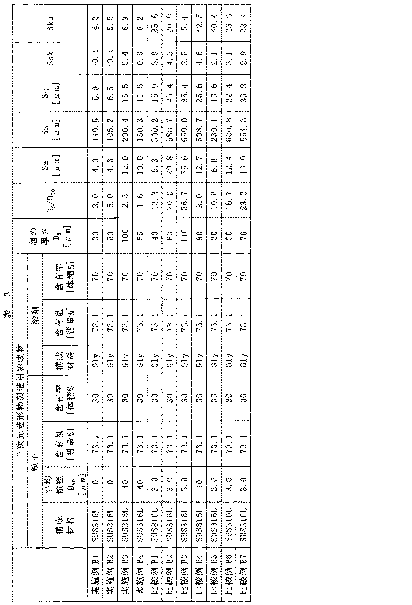
[6]評価
[6.1]三次元造形物の寸法精度
前記各実施例および各比較例の三次元造形物について、厚さ、幅、長さを測定し、設計値からのずれ量を求め、以下の基準に従い評価した。
A:厚さ、幅、長さのうち、設計値からのずれ量が最も大きいものについての設計値からのずれ量が1.0%未満である。
B:厚さ、幅、長さのうち、設計値からのずれ量が最も大きいものについての設計値からのずれ量が1.0%以上2.0%未満である。
C:厚さ、幅、長さのうち、設計値からのずれ量が最も大きいものについての設計値からのずれ量が2.0%以上4.0%未満である。
D:厚さ、幅、長さのうち、設計値からのずれ量が最も大きいものについての設計値からのずれ量が4.0%以上7.0%未満である。
E:厚さ、幅、長さのうち、設計値からのずれ量が最も大きいものについての設計値からのずれ量が7.0%以上である。 [6] Evaluation [6.1] Dimensional accuracy of three-dimensional structure The thickness, width, and length of the three-dimensional structure of each of the examples and comparative examples are measured, and the amount of deviation from the design value is obtained. The evaluation was made according to the following criteria.
A: The deviation from the design value for the largest deviation from the design value among the thickness, width, and length is less than 1.0%.
B: The deviation amount from the design value of the thickness, width, and length having the largest deviation amount from the design value is 1.0% or more and less than 2.0%.
C: Among thickness, width, and length, the deviation from the design value for the largest deviation from the design value is 2.0% or more and less than 4.0%.
D: Among the thickness, width, and length, the deviation from the design value for the largest deviation from the design value is 4.0% or more and less than 7.0%.
E: The deviation from the design value for the largest deviation from the design value among the thickness, width, and length is 7.0% or more.
[6.2]強度
前記各実施例および各比較例の三次元造形物について、JIS K 7171:1994(ISO 178:1993)に準拠し、支点間距離64mm、試験速度:2mm/分という条件で測定を行い、曲げ強度について、以下の基準に従い評価した。
A:曲げ強度が65MPa以上。
B:曲げ強度が60MPa以上65MPa未満。
C:曲げ強度が45MPa以上60MPa未満。
D:曲げ強度が30MPa以上45MPa未満。
E:曲げ強度が30MPa未満。
これらの結果を表4にまとめて示す。 [6.2] Strength With respect to the three-dimensional structure of each of the above Examples and Comparative Examples, the distance between fulcrums was 64 mm and the test speed was 2 mm / min in accordance with JIS K 7171: 1994 (ISO 178: 1993). Measurement was performed and bending strength was evaluated according to the following criteria.
A: Bending strength is 65 MPa or more.
B: The bending strength is 60 MPa or more and less than 65 MPa.
C: Bending strength is 45 MPa or more and less than 60 MPa.
D: Bending strength is 30 MPa or more and less than 45 MPa.
E: Bending strength is less than 30 MPa.
These results are summarized in Table 4.

表4から明らかなように、本発明では、寸法精度、強度に優れ、信頼性の高い三次元造形物を製造することができた。これに対し、比較例では、満足のいく結果が得られなかった。
As is apparent from Table 4, the present invention was able to produce a highly reliable three-dimensional structure with excellent dimensional accuracy and strength. On the other hand, in the comparative example, a satisfactory result was not obtained.
10…三次元造形物、1…層、2’…組成物(三次元造形物製造用組成物)、2A’…組成物(サポート部形成用組成物)、2B’…組成物(実体部形成用組成物)、21…粒子(分散質)、21A…粒子(分散質)、21B…粒子(分散質)、2A…第1のパターン(サポート部用パターン)、2B…第2のパターン(実体部用パターン)、3…接合部、3A…接合部(第1の接合部)、3B…接合部(第2の接合部)、4…実体部、5…サポート部(支持部、サポート材)、M100…三次元造形物製造装置、M2…制御部、M21…コンピューター、M22…駆動制御部、M3…組成物供給手段(吐出手段)、M3A…第1の組成物供給手段(第1の吐出手段)、M3B…第2の組成物供給手段(第2の吐出手段)、M4…層形成部、M41…ステージ(昇降ステージ)、M410…平面(受液面)、M45…枠体、M5…ガイド、M6…レーザー光照射手段、M7…組成物載置部(組成物仮置部)、M8…平坦化手段、M9…組成物供給手段、L…レーザー光
DESCRIPTION OF SYMBOLS 10 ... Three-dimensional structure, 1 ... Layer, 2 '... Composition (Composition for three-dimensional structure manufacture), 2A' ... Composition (Composition for support part formation), 2B '... Composition (Substantial part formation) Composition), 21 ... particle (dispersoid), 21A ... particle (dispersoid), 21B ... particle (dispersoid), 2A ... first pattern (support part pattern), 2B ... second pattern (substance) Part pattern), 3 ... joining part, 3A ... joining part (first joining part), 3B ... joining part (second joining part), 4 ... substantive part, 5 ... support part (supporting part, support material) M100: Three-dimensional structure manufacturing apparatus, M2: Control unit, M21: Computer, M22: Drive control unit, M3: Composition supply means (discharge means), M3A: First composition supply means (first discharge) Means), M3B... Second composition supply means (second discharge means), M4. M41 ... Stage (elevating stage), M410 ... Flat surface (liquid receiving surface), M45 ... Frame body, M5 ... Guide, M6 ... Laser light irradiation means, M7 ... Composition placement section (composition temporary placement section), M8 ... Flattening means, M9 ... composition supplying means, L ... laser light
Claims (6)
- 複数の層を積層して三次元造形物を製造する方法であって、
複数個の粒子を含む組成物を用いて前記層を形成する層形成工程と、前記層にレーザー光を照射し、前記層中に含まれる前記粒子同士を接合する接合工程とを含む一連の工程を繰り返し行い、
前記粒子の平均粒径をD50[μm]、前記層形成工程で形成された前記層の厚さをDS[μm]としたとき、DS/D50<5.0の関係を満たし、
前記接合工程により前記粒子同士が接合された状態の前記層の表面の算術平均高さSaが15μm以下であることを特徴とする三次元造形物の製造方法。 A method for producing a three-dimensional structure by laminating a plurality of layers,
A series of steps including a layer forming step of forming the layer using a composition including a plurality of particles, and a bonding step of irradiating the layer with laser light and bonding the particles contained in the layer. Repeatedly
When the average particle diameter of the particles is D 50 [μm] and the thickness of the layer formed in the layer forming step is D S [μm], the relationship of D S / D 50 <5.0 is satisfied,
The method for producing a three-dimensional structure, wherein an arithmetic average height Sa of the surface of the layer in a state where the particles are bonded by the bonding step is 15 μm or less. - 前記接合工程により前記粒子同士が接合された状態の前記層の表面の最大高さSzが250μm以下である請求項1に記載の三次元造形物の製造方法。 The method for producing a three-dimensional structure according to claim 1, wherein the maximum height Sz of the surface of the layer in a state where the particles are bonded by the bonding step is 250 µm or less.
- 前記組成物を吐出して前記層を形成する請求項1または2に記載の三次元造形物の製造方法。 The method for producing a three-dimensional structure according to claim 1 or 2, wherein the layer is formed by discharging the composition.
- 前記組成物を平坦化手段により平坦化して前記層を形成する請求項1または2に記載の三次元造形物の製造方法。 The method for producing a three-dimensional structure according to claim 1 or 2, wherein the composition is flattened by a flattening means to form the layer.
- 前記層形成工程で形成された前記層の厚さDSが、5μm以上300μm以下である請求項1ないし4のいずれか1項に記載の三次元造形物の製造方法。 Manufacturing method of the layer thickness D S of the layer formed in the forming step, the 3D object according to any one of claims 1 to 4 is 5μm or more 300μm or less.
- 前記粒子の平均粒径D50が、0.1μm以上50μm未満である請求項1ないし5のいずれか1項に記載の三次元造形物の製造方法。 Method for producing a mean particle diameter D 50 of the three-dimensional model according to any one of claims 1 to 5 or more and less than 0.1 [mu] m 50 [mu] m of the particles.
Priority Applications (3)
| Application Number | Priority Date | Filing Date | Title |
|---|---|---|---|
| CN201880022093.4A CN110475634B (en) | 2017-03-31 | 2018-03-27 | Method for manufacturing three-dimensional shaped object |
| US16/498,455 US11383303B2 (en) | 2017-03-31 | 2018-03-27 | Production method for three-dimensional shaped article |
| EP18777429.4A EP3603852A4 (en) | 2017-03-31 | 2018-03-27 | Three-dimensional object production method |
Applications Claiming Priority (2)
| Application Number | Priority Date | Filing Date | Title |
|---|---|---|---|
| JP2017-073075 | 2017-03-31 | ||
| JP2017073075A JP6907657B2 (en) | 2017-03-31 | 2017-03-31 | Manufacturing method of 3D model |
Publications (1)
| Publication Number | Publication Date |
|---|---|
| WO2018181275A1 true WO2018181275A1 (en) | 2018-10-04 |
Family
ID=63676178
Family Applications (1)
| Application Number | Title | Priority Date | Filing Date |
|---|---|---|---|
| PCT/JP2018/012355 WO2018181275A1 (en) | 2017-03-31 | 2018-03-27 | Three-dimensional object production method |
Country Status (5)
| Country | Link |
|---|---|
| US (1) | US11383303B2 (en) |
| EP (1) | EP3603852A4 (en) |
| JP (1) | JP6907657B2 (en) |
| CN (1) | CN110475634B (en) |
| WO (1) | WO2018181275A1 (en) |
Families Citing this family (2)
| Publication number | Priority date | Publication date | Assignee | Title |
|---|---|---|---|---|
| US11421119B2 (en) * | 2017-01-12 | 2022-08-23 | Konica Minolta, Inc. | Resin composition, and three-dimensional moulding production method |
| JP2022175662A (en) * | 2021-05-14 | 2022-11-25 | トヨタ自動車株式会社 | Method for manufacturing laminated molded article |
Citations (4)
| Publication number | Priority date | Publication date | Assignee | Title |
|---|---|---|---|---|
| JP2000336403A (en) * | 1999-05-26 | 2000-12-05 | Matsushita Electric Works Ltd | Production of shaped part with three dimensional form |
| JP2005536324A (en) * | 2002-06-18 | 2005-12-02 | ダイムラークライスラー・アクチェンゲゼルシャフト | Laser sintering method with increased processing accuracy and particles used in the method |
| JP2008184623A (en) | 2007-01-26 | 2008-08-14 | Matsushita Electric Works Ltd | Method for producing three-dimensional molding, and material |
| JP2009001900A (en) * | 2007-05-23 | 2009-01-08 | Panasonic Electric Works Co Ltd | Process for three-dimensional configuration modeling |
Family Cites Families (13)
| Publication number | Priority date | Publication date | Assignee | Title |
|---|---|---|---|---|
| DE102005022308B4 (en) | 2005-05-13 | 2007-03-22 | Eos Gmbh Electro Optical Systems | Apparatus and method for manufacturing a three-dimensional object with a heated powder coating material build-up material |
| DE112011101779T5 (en) * | 2010-05-25 | 2013-03-14 | Panasonic Corporation | Metal powder for selective laser sintering, process for producing a three-dimensional molded article using the same, and three-dimensional molded article obtained therefrom |
| JP6379850B2 (en) * | 2013-10-11 | 2018-08-29 | セイコーエプソン株式会社 | Powder for laser sintering and method for producing structure |
| JP2015196267A (en) * | 2014-03-31 | 2015-11-09 | 株式会社東芝 | Method and apparatus for production of laminated molding and slurry |
| JP5721887B1 (en) * | 2014-06-20 | 2015-05-20 | 株式会社ソディック | Additive manufacturing equipment |
| US10667403B2 (en) | 2014-09-19 | 2020-05-26 | Fuji Corporation | Manufacturing apparatus for performing additive manufacturing of an electrical device |
| CN104259459B (en) * | 2014-09-29 | 2016-08-24 | 飞而康快速制造科技有限责任公司 | A kind of method using selective laser melting process to prepare titanium alloy handicraft |
| CN106715085B (en) * | 2014-09-30 | 2020-01-14 | 惠普发展公司有限责任合伙企业 | Generating three-dimensional objects |
| JP6515557B2 (en) * | 2015-02-04 | 2019-05-22 | セイコーエプソン株式会社 | Member for manufacturing three-dimensional object, apparatus for manufacturing three-dimensional object, method for manufacturing three-dimensional object, and three-dimensional object |
| JP2016172893A (en) * | 2015-03-17 | 2016-09-29 | セイコーエプソン株式会社 | Three-dimensional formation device and three-dimensional formation method |
| CN107921710A (en) * | 2015-07-17 | 2018-04-17 | 应用材料公司 | Selective material distribution and multilayered molten in increasing material manufacturing |
| CN107921536A (en) * | 2015-07-18 | 2018-04-17 | 伏尔肯模型公司 | The increasing material manufacturing of the material fusion controlled by space |
| CN105537589B (en) * | 2016-01-28 | 2018-12-25 | 佛山市安齿生物科技有限公司 | A kind of SLM molding surface treatment method of titanium implant |
-
2017
- 2017-03-31 JP JP2017073075A patent/JP6907657B2/en active Active
-
2018
- 2018-03-27 CN CN201880022093.4A patent/CN110475634B/en active Active
- 2018-03-27 WO PCT/JP2018/012355 patent/WO2018181275A1/en active Application Filing
- 2018-03-27 EP EP18777429.4A patent/EP3603852A4/en active Pending
- 2018-03-27 US US16/498,455 patent/US11383303B2/en active Active
Patent Citations (4)
| Publication number | Priority date | Publication date | Assignee | Title |
|---|---|---|---|---|
| JP2000336403A (en) * | 1999-05-26 | 2000-12-05 | Matsushita Electric Works Ltd | Production of shaped part with three dimensional form |
| JP2005536324A (en) * | 2002-06-18 | 2005-12-02 | ダイムラークライスラー・アクチェンゲゼルシャフト | Laser sintering method with increased processing accuracy and particles used in the method |
| JP2008184623A (en) | 2007-01-26 | 2008-08-14 | Matsushita Electric Works Ltd | Method for producing three-dimensional molding, and material |
| JP2009001900A (en) * | 2007-05-23 | 2009-01-08 | Panasonic Electric Works Co Ltd | Process for three-dimensional configuration modeling |
Non-Patent Citations (1)
| Title |
|---|
| See also references of EP3603852A4 |
Also Published As
| Publication number | Publication date |
|---|---|
| US11383303B2 (en) | 2022-07-12 |
| EP3603852A1 (en) | 2020-02-05 |
| JP2018172766A (en) | 2018-11-08 |
| EP3603852A4 (en) | 2020-11-11 |
| US20210213533A1 (en) | 2021-07-15 |
| CN110475634A (en) | 2019-11-19 |
| JP6907657B2 (en) | 2021-07-21 |
| CN110475634B (en) | 2022-06-10 |
Similar Documents
| Publication | Publication Date | Title |
|---|---|---|
| WO2018159133A1 (en) | Composition for manufacturing three-dimensional printed article, method for manufacturing three-dimensional printed article, and device for manufacturing three-dimensional printed article | |
| JP2015189007A (en) | Production method of shaped article | |
| JP6669985B2 (en) | Manufacturing method of three-dimensional objects | |
| JP6825293B2 (en) | Composition for manufacturing 3D model and manufacturing method of 3D model | |
| TW201609606A (en) | Sintering and shaping method, liquid binding agent, and sintered shaped article | |
| JP2018141225A (en) | Composition for producing three-dimensional molded article, and method for producing three-dimensional molded article | |
| JP2017110271A (en) | Method for manufacturing three-dimensional molded object, apparatus for manufacturing three-dimensional molded object, and three-dimensional molded object | |
| JP2017031490A (en) | Method for manufacturing three-dimensional molded object, apparatus for manufacturing three-dimensional molded object, three-dimensional molded object, and composition for manufacturing three-dimensional molded object | |
| JP6720608B2 (en) | Method for manufacturing three-dimensional model | |
| WO2018181275A1 (en) | Three-dimensional object production method | |
| JP2021075753A (en) | Powder for manufacturing three-dimensional molded article, composition for manufacturing three-dimensional molded article and method for manufacturing three-dimensional molded article | |
| JP2015189024A (en) | Production method of shaped article | |
| JP2017160471A (en) | Method of producing three-dimensional modeled product, apparatus for producing three-dimensional modeled product, and three-dimensional modeled product | |
| WO2018159134A1 (en) | Composition for manufacturing three-dimensional shaped article, method of manufacturing three-dimensional shaped article, and apparatus for manufacturing three-dimensional shaped article | |
| JP2017159474A (en) | Method of producing three-dimensional modeled product, apparatus for producing three-dimensional modeled product, and three-dimensional modeled product | |
| JP2017136712A (en) | Method for manufacturing three-dimensional molded object, apparatus for manufacturing three-dimensional molded object and three-dimensional molded object | |
| JP2018159110A (en) | Composition and method for producing three-dimensional molding | |
| JP2017177510A (en) | Three-dimensional molded article manufacturing method, three-dimensional molded article manufacturing device, and three-dimensional molded article | |
| JP2017113888A (en) | Method for manufacturing three-dimensional molded article, apparatus for manufacturing three-dimensional molded article, three-dimensional molded article and composition for manufacturing three-dimensional molded article | |
| JP2018141222A (en) | Composition for producing three-dimensional molded article, and method for producing three-dimensional molded article | |
| JP2018052084A (en) | Composition for manufacturing three-dimensional shaped article, set of compositions for manufacturing three-dimensional shaped article, method for manufacturing three-dimensional shaped article and apparatus for manufacturing three-dimensional shaped article | |
| JP2021050407A (en) | Composition for the production of three-dimensional molding | |
| JP2017127975A (en) | Sinter molding method and sinter-molded object | |
| JP2021055157A (en) | Composition for manufacturing three-dimensionally molded article | |
| JP2017171959A (en) | Manufacturing method for three-dimensional shaped article |
Legal Events
| Date | Code | Title | Description |
|---|---|---|---|
| 121 | Ep: the epo has been informed by wipo that ep was designated in this application |
Ref document number: 18777429 Country of ref document: EP Kind code of ref document: A1 |
|
| NENP | Non-entry into the national phase |
Ref country code: DE |
|
| WWE | Wipo information: entry into national phase |
Ref document number: 2018777429 Country of ref document: EP |
|
| ENP | Entry into the national phase |
Ref document number: 2018777429 Country of ref document: EP Effective date: 20191031 |