WO2018180337A1 - 冷凍機制御装置、ターボ冷凍機、冷凍機制御方法およびプログラム - Google Patents
冷凍機制御装置、ターボ冷凍機、冷凍機制御方法およびプログラム Download PDFInfo
- Publication number
- WO2018180337A1 WO2018180337A1 PCT/JP2018/008983 JP2018008983W WO2018180337A1 WO 2018180337 A1 WO2018180337 A1 WO 2018180337A1 JP 2018008983 W JP2018008983 W JP 2018008983W WO 2018180337 A1 WO2018180337 A1 WO 2018180337A1
- Authority
- WO
- WIPO (PCT)
- Prior art keywords
- pressure
- refrigerant
- cold water
- temperature
- oil tank
- Prior art date
- Legal status (The legal status is an assumption and is not a legal conclusion. Google has not performed a legal analysis and makes no representation as to the accuracy of the status listed.)
- Ceased
Links
Images


Classifications
-
- F—MECHANICAL ENGINEERING; LIGHTING; HEATING; WEAPONS; BLASTING
- F25—REFRIGERATION OR COOLING; COMBINED HEATING AND REFRIGERATION SYSTEMS; HEAT PUMP SYSTEMS; MANUFACTURE OR STORAGE OF ICE; LIQUEFACTION SOLIDIFICATION OF GASES
- F25B—REFRIGERATION MACHINES, PLANTS OR SYSTEMS; COMBINED HEATING AND REFRIGERATION SYSTEMS; HEAT PUMP SYSTEMS
- F25B49/00—Arrangement or mounting of control or safety devices
- F25B49/005—Arrangement or mounting of control or safety devices of safety devices
-
- F—MECHANICAL ENGINEERING; LIGHTING; HEATING; WEAPONS; BLASTING
- F25—REFRIGERATION OR COOLING; COMBINED HEATING AND REFRIGERATION SYSTEMS; HEAT PUMP SYSTEMS; MANUFACTURE OR STORAGE OF ICE; LIQUEFACTION SOLIDIFICATION OF GASES
- F25B—REFRIGERATION MACHINES, PLANTS OR SYSTEMS; COMBINED HEATING AND REFRIGERATION SYSTEMS; HEAT PUMP SYSTEMS
- F25B1/00—Compression machines, plants or systems with non-reversible cycle
- F25B1/04—Compression machines, plants or systems with non-reversible cycle with compressor of rotary type
- F25B1/053—Compression machines, plants or systems with non-reversible cycle with compressor of rotary type of turbine type
-
- F—MECHANICAL ENGINEERING; LIGHTING; HEATING; WEAPONS; BLASTING
- F25—REFRIGERATION OR COOLING; COMBINED HEATING AND REFRIGERATION SYSTEMS; HEAT PUMP SYSTEMS; MANUFACTURE OR STORAGE OF ICE; LIQUEFACTION SOLIDIFICATION OF GASES
- F25B—REFRIGERATION MACHINES, PLANTS OR SYSTEMS; COMBINED HEATING AND REFRIGERATION SYSTEMS; HEAT PUMP SYSTEMS
- F25B49/00—Arrangement or mounting of control or safety devices
- F25B49/02—Arrangement or mounting of control or safety devices for compression type machines, plants or systems
-
- F—MECHANICAL ENGINEERING; LIGHTING; HEATING; WEAPONS; BLASTING
- F04—POSITIVE - DISPLACEMENT MACHINES FOR LIQUIDS; PUMPS FOR LIQUIDS OR ELASTIC FLUIDS
- F04D—NON-POSITIVE-DISPLACEMENT PUMPS
- F04D27/00—Control, e.g. regulation, of pumps, pumping installations or pumping systems specially adapted for elastic fluids
- F04D27/02—Surge control
- F04D27/0246—Surge control by varying geometry within the pumps, e.g. by adjusting vanes
-
- F—MECHANICAL ENGINEERING; LIGHTING; HEATING; WEAPONS; BLASTING
- F04—POSITIVE - DISPLACEMENT MACHINES FOR LIQUIDS; PUMPS FOR LIQUIDS OR ELASTIC FLUIDS
- F04D—NON-POSITIVE-DISPLACEMENT PUMPS
- F04D27/00—Control, e.g. regulation, of pumps, pumping installations or pumping systems specially adapted for elastic fluids
- F04D27/02—Surge control
- F04D27/0261—Surge control by varying driving speed
-
- F—MECHANICAL ENGINEERING; LIGHTING; HEATING; WEAPONS; BLASTING
- F05—INDEXING SCHEMES RELATING TO ENGINES OR PUMPS IN VARIOUS SUBCLASSES OF CLASSES F01-F04
- F05D—INDEXING SCHEME FOR ASPECTS RELATING TO NON-POSITIVE-DISPLACEMENT MACHINES OR ENGINES, GAS-TURBINES OR JET-PROPULSION PLANTS
- F05D2250/00—Geometry
- F05D2250/50—Inlet or outlet
- F05D2250/51—Inlet
-
- F—MECHANICAL ENGINEERING; LIGHTING; HEATING; WEAPONS; BLASTING
- F25—REFRIGERATION OR COOLING; COMBINED HEATING AND REFRIGERATION SYSTEMS; HEAT PUMP SYSTEMS; MANUFACTURE OR STORAGE OF ICE; LIQUEFACTION SOLIDIFICATION OF GASES
- F25B—REFRIGERATION MACHINES, PLANTS OR SYSTEMS; COMBINED HEATING AND REFRIGERATION SYSTEMS; HEAT PUMP SYSTEMS
- F25B2339/00—Details of evaporators; Details of condensers
- F25B2339/04—Details of condensers
- F25B2339/047—Water-cooled condensers
-
- F—MECHANICAL ENGINEERING; LIGHTING; HEATING; WEAPONS; BLASTING
- F25—REFRIGERATION OR COOLING; COMBINED HEATING AND REFRIGERATION SYSTEMS; HEAT PUMP SYSTEMS; MANUFACTURE OR STORAGE OF ICE; LIQUEFACTION SOLIDIFICATION OF GASES
- F25B—REFRIGERATION MACHINES, PLANTS OR SYSTEMS; COMBINED HEATING AND REFRIGERATION SYSTEMS; HEAT PUMP SYSTEMS
- F25B25/00—Machines, plants or systems, using a combination of modes of operation covered by two or more of the groups F25B1/00 - F25B23/00
- F25B25/005—Machines, plants or systems, using a combination of modes of operation covered by two or more of the groups F25B1/00 - F25B23/00 using primary and secondary systems
-
- F—MECHANICAL ENGINEERING; LIGHTING; HEATING; WEAPONS; BLASTING
- F25—REFRIGERATION OR COOLING; COMBINED HEATING AND REFRIGERATION SYSTEMS; HEAT PUMP SYSTEMS; MANUFACTURE OR STORAGE OF ICE; LIQUEFACTION SOLIDIFICATION OF GASES
- F25B—REFRIGERATION MACHINES, PLANTS OR SYSTEMS; COMBINED HEATING AND REFRIGERATION SYSTEMS; HEAT PUMP SYSTEMS
- F25B2500/00—Problems to be solved
- F25B2500/16—Lubrication
-
- F—MECHANICAL ENGINEERING; LIGHTING; HEATING; WEAPONS; BLASTING
- F25—REFRIGERATION OR COOLING; COMBINED HEATING AND REFRIGERATION SYSTEMS; HEAT PUMP SYSTEMS; MANUFACTURE OR STORAGE OF ICE; LIQUEFACTION SOLIDIFICATION OF GASES
- F25B—REFRIGERATION MACHINES, PLANTS OR SYSTEMS; COMBINED HEATING AND REFRIGERATION SYSTEMS; HEAT PUMP SYSTEMS
- F25B2600/00—Control issues
- F25B2600/25—Control of valves
- F25B2600/2513—Expansion valves
-
- F—MECHANICAL ENGINEERING; LIGHTING; HEATING; WEAPONS; BLASTING
- F25—REFRIGERATION OR COOLING; COMBINED HEATING AND REFRIGERATION SYSTEMS; HEAT PUMP SYSTEMS; MANUFACTURE OR STORAGE OF ICE; LIQUEFACTION SOLIDIFICATION OF GASES
- F25B—REFRIGERATION MACHINES, PLANTS OR SYSTEMS; COMBINED HEATING AND REFRIGERATION SYSTEMS; HEAT PUMP SYSTEMS
- F25B2700/00—Sensing or detecting of parameters; Sensors therefor
- F25B2700/13—Mass flow of refrigerants
- F25B2700/135—Mass flow of refrigerants through the evaporator
- F25B2700/1352—Mass flow of refrigerants through the evaporator at the inlet
-
- F—MECHANICAL ENGINEERING; LIGHTING; HEATING; WEAPONS; BLASTING
- F25—REFRIGERATION OR COOLING; COMBINED HEATING AND REFRIGERATION SYSTEMS; HEAT PUMP SYSTEMS; MANUFACTURE OR STORAGE OF ICE; LIQUEFACTION SOLIDIFICATION OF GASES
- F25B—REFRIGERATION MACHINES, PLANTS OR SYSTEMS; COMBINED HEATING AND REFRIGERATION SYSTEMS; HEAT PUMP SYSTEMS
- F25B2700/00—Sensing or detecting of parameters; Sensors therefor
- F25B2700/19—Pressures
- F25B2700/193—Pressures of the compressor
- F25B2700/1932—Oil pressures
-
- F—MECHANICAL ENGINEERING; LIGHTING; HEATING; WEAPONS; BLASTING
- F25—REFRIGERATION OR COOLING; COMBINED HEATING AND REFRIGERATION SYSTEMS; HEAT PUMP SYSTEMS; MANUFACTURE OR STORAGE OF ICE; LIQUEFACTION SOLIDIFICATION OF GASES
- F25B—REFRIGERATION MACHINES, PLANTS OR SYSTEMS; COMBINED HEATING AND REFRIGERATION SYSTEMS; HEAT PUMP SYSTEMS
- F25B2700/00—Sensing or detecting of parameters; Sensors therefor
- F25B2700/21—Temperatures
- F25B2700/2105—Oil temperatures
-
- F—MECHANICAL ENGINEERING; LIGHTING; HEATING; WEAPONS; BLASTING
- F25—REFRIGERATION OR COOLING; COMBINED HEATING AND REFRIGERATION SYSTEMS; HEAT PUMP SYSTEMS; MANUFACTURE OR STORAGE OF ICE; LIQUEFACTION SOLIDIFICATION OF GASES
- F25B—REFRIGERATION MACHINES, PLANTS OR SYSTEMS; COMBINED HEATING AND REFRIGERATION SYSTEMS; HEAT PUMP SYSTEMS
- F25B2700/00—Sensing or detecting of parameters; Sensors therefor
- F25B2700/21—Temperatures
- F25B2700/2117—Temperatures of an evaporator
- F25B2700/21171—Temperatures of an evaporator of the fluid cooled by the evaporator
- F25B2700/21172—Temperatures of an evaporator of the fluid cooled by the evaporator at the inlet
-
- F—MECHANICAL ENGINEERING; LIGHTING; HEATING; WEAPONS; BLASTING
- F25—REFRIGERATION OR COOLING; COMBINED HEATING AND REFRIGERATION SYSTEMS; HEAT PUMP SYSTEMS; MANUFACTURE OR STORAGE OF ICE; LIQUEFACTION SOLIDIFICATION OF GASES
- F25B—REFRIGERATION MACHINES, PLANTS OR SYSTEMS; COMBINED HEATING AND REFRIGERATION SYSTEMS; HEAT PUMP SYSTEMS
- F25B2700/00—Sensing or detecting of parameters; Sensors therefor
- F25B2700/21—Temperatures
- F25B2700/2117—Temperatures of an evaporator
- F25B2700/21171—Temperatures of an evaporator of the fluid cooled by the evaporator
- F25B2700/21173—Temperatures of an evaporator of the fluid cooled by the evaporator at the outlet
-
- F—MECHANICAL ENGINEERING; LIGHTING; HEATING; WEAPONS; BLASTING
- F25—REFRIGERATION OR COOLING; COMBINED HEATING AND REFRIGERATION SYSTEMS; HEAT PUMP SYSTEMS; MANUFACTURE OR STORAGE OF ICE; LIQUEFACTION SOLIDIFICATION OF GASES
- F25B—REFRIGERATION MACHINES, PLANTS OR SYSTEMS; COMBINED HEATING AND REFRIGERATION SYSTEMS; HEAT PUMP SYSTEMS
- F25B31/00—Compressor arrangements
- F25B31/002—Lubrication
- F25B31/004—Lubrication oil recirculating arrangements
-
- Y—GENERAL TAGGING OF NEW TECHNOLOGICAL DEVELOPMENTS; GENERAL TAGGING OF CROSS-SECTIONAL TECHNOLOGIES SPANNING OVER SEVERAL SECTIONS OF THE IPC; TECHNICAL SUBJECTS COVERED BY FORMER USPC CROSS-REFERENCE ART COLLECTIONS [XRACs] AND DIGESTS
- Y02—TECHNOLOGIES OR APPLICATIONS FOR MITIGATION OR ADAPTATION AGAINST CLIMATE CHANGE
- Y02B—CLIMATE CHANGE MITIGATION TECHNOLOGIES RELATED TO BUILDINGS, e.g. HOUSING, HOUSE APPLIANCES OR RELATED END-USER APPLICATIONS
- Y02B30/00—Energy efficient heating, ventilation or air conditioning [HVAC]
- Y02B30/70—Efficient control or regulation technologies, e.g. for control of refrigerant flow, motor or heating
Definitions
- the present invention relates to a refrigerator control device, a turbo refrigerator, a refrigerator control method, and a program.
- HFC (CFC substitute) refrigerants used in turbo refrigerators have several hundred to several thousand GWP (Global Warming Potential), and HFO refrigerants with a single digit GWP in consideration of environmental considerations. Conversion is necessary.
- a low pressure refrigerant such as non-combustible HFO-1233zd (E) may be used as a chiller refrigerant.
- a turbo refrigerator generally includes an oil tank in which lubricating oil to be supplied to a turbo compressor is stored.
- the specific volume of the refrigerant gas of FO-1233zd (E) is about five times that of HFC-134a.
- the gas volume increases when the pressure in the oil tank becomes lower than the atmospheric pressure. That is, in a refrigerator using a low pressure refrigerant, when the refrigerant of the same mass dissolved in the lubricating oil in the oil tank is reduced in pressure and evaporated, compared to a refrigerator using a high pressure refrigerant, The volume is increased, and it is easy to cause forming to cause foaming in the lubricating oil of the oil tank. In particular, at the time of start-up where the pressure decrease speed on the low pressure side is large, forming is likely to occur in the lubricating oil in the oil tank.
- Patent Document 1 when the turbo compressor is started, the opening degree of the suction capacity control unit is started with an opening smaller than the target opening, and then the target opening is quickly opened to the target opening. It is disclosed that the operation time is as short as possible to reduce the passage resistance of the refrigerant and suppress the pressure drop on the downstream side of the suction capacity control unit to suppress the generation of the forming.
- the amount of refrigerant dissolved in the lubricating oil differs depending on the pressure value even at the same pressure decrease rate, the amount of refrigerant dissolved out from the lubricating oil differs depending on the pressure in the oil tank. Further, the amount of refrigerant dissolved in the lubricating oil also depends on the temperature. Therefore, it is required to more reliably suppress the forming in the oil tank.
- An object of the present invention is to provide a refrigerator control device, a turbo refrigerator, a refrigerator control method, and a program that can more reliably suppress forming in an oil tank.
- a turbocompressor for compressing a refrigerant gas
- a condenser for radiating the heat of the refrigerant gas compressed by the turbocompressor by heat exchange and condensing the refrigerant gas
- a condenser An expansion valve for expanding the liquid refrigerant, and an evaporator for absorbing the heat of the liquid refrigerant expanded by the expansion valve by heat exchange and evaporating it to lower the temperature of the cold water introduced from the cold water inlet and let it flow out from the cold water outlet
- An oil tank for storing lubricating oil to be supplied to the turbo compressor, and a pressure equalizing pipe connecting the oil tank and the evaporator;
- a pressure adjusting unit for adjusting the pressure of the evaporator based on the specified pressure reduction speed, and the pressure reduction speed characteristic is specified.
- a volume control unit for calculating a volume of refrigerant gas deposited from the lubricating oil when the pressure is reduced at a predetermined pressure reduction rate, the calculated volume, and a volume on the oil surface of the oil tank And a determination unit that determines whether or not the forming can be permitted based on the comparison with the above.
- the refrigerator control device wherein the amount of decrease in evaporation temperature according to the specified decompression speed is calculated, and the current target value of the temperature of the cold water outlet
- the system further comprises a cold water outlet temperature setting unit that sets a value obtained by subtracting the amount of decrease of the evaporation temperature from a certain setting cold water outlet temperature as a new setting cold water outlet temperature, and the pressure adjustment unit measures the measured value of the temperature of the cold water outlet The pressure of the evaporator is adjusted to match the set chilled water outlet temperature set by the chilled water outlet temperature setting unit.
- a turbocompressor for compressing a refrigerant gas
- a condenser for radiating the heat of the refrigerant gas compressed by the turbocompressor by heat exchange and condensing the refrigerant, and the condenser.
- the pressure reduction rate specification unit is a refrigerant deposition gas volume calculation unit that calculates the volume of refrigerant gas deposited from the lubricating oil when pressure reduction is performed at a predetermined pressure reduction rate, the calculated volume, and the oil of the oil tank And a determination unit that determines whether the forming can be allowed based on the comparison with the volume on the surface.
- a turbocompressor for compressing a refrigerant gas
- a condenser for radiating the heat of the refrigerant gas compressed by the turbocompressor by heat exchange and condensing the same, and the condenser.
- a method of controlling a turbo refrigerator comprising: an oil tank for storing lubricating oil supplied to the turbo compressor; and a pressure equalizing pipe connecting the oil tank and the evaporator by a refrigerator control device.
- the refrigerator control device determines the pressure of the evaporator based on the specified decompression rate and a decompression rate identification unit that identifies the decompression rate at which forming does not occur in the oil tank.
- a pressure adjustment unit for adjusting the pressure reduction unit includes a refrigerant deposition gas volume calculation unit and a determination unit, and the pressure is reduced at a predetermined pressure reduction rate by the refrigerant deposition gas volume calculation unit Is the volume of refrigerant gas deposited from the lubricating oil calculated, and the forming can be allowed based on the comparison of the calculated volume by the determination unit and the volume on the oil surface of the oil tank? It is a refrigerator control method which judges whether or not.
- a turbocompressor for compressing a refrigerant gas
- a condenser for radiating the heat of the refrigerant gas compressed by the turbocompressor by heat exchange and condensing the refrigerant gas
- a condenser An expansion valve for expanding the liquid refrigerant, and an evaporator for absorbing the heat of the liquid refrigerant expanded by the expansion valve by heat exchange and evaporating it to lower the temperature of the cold water introduced from the cold water inlet and let it flow out from the cold water outlet
- a program for controlling a turbo refrigerator comprising: an oil tank storing lubricating oil to be supplied to the turbo compressor; and a pressure equalizing pipe connecting the oil tank and the evaporator by a refrigerator control device
- the refrigerator control device is configured to specify the pressure reduction rate at which no forming occurs in the oil tank, and the steaming rate based on the specified pressure reduction rate.
- It has a pressure regulator for adjusting the pressure of the vessel, and the pressure reduction rate specifying unit, and the refrigerant deposition gas volume calculation unit, and a determination section, by the refrigerant deposition gas volume calculation unit.
- the pressure is reduced at a predetermined pressure reduction rate, the volume of refrigerant gas deposited from the lubricating oil is calculated, and the determination unit compares the calculated volume with the volume on the oil surface of the oil tank.
- FIG. 1 shows the operation example of the refrigerator control apparatus shown in FIG.
- FIG. 2 shows the operation example of the refrigerator control apparatus shown in FIG.
- the graph which showed the relationship between pressure and temperature, and the amount of refrigerant dissolution. It is a figure for demonstrating the operation example of the refrigerator control apparatus shown in FIG.
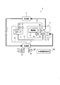
- FIG. 1 is a view showing an entire configuration of a turbo refrigerator according to a first embodiment.
- the turbo refrigerator 1 includes a turbo compressor 3, a condenser 5, an expansion valve 7, an evaporator 9, and a refrigerator control device 100.
- the turbo compressor 3 compresses a refrigerant.
- the condenser 5 condenses the high-temperature high-pressure gas refrigerant compressed by the turbo compressor 3.
- the expansion valve 7 expands the liquid refrigerant introduced from the condenser 5.
- the evaporator 9 evaporates the liquid refrigerant expanded by the expansion valve 7.
- the refrigerator control device 100 controls the turbo compressor 3, the condenser 5, the expansion valve 7, the evaporator 9, and the like.
- the refrigerant used in the turbo refrigerator 1 can be, for example, a low pressure refrigerant such as HFO-1233zd (E), but is not limited thereto.
- the turbo compressor 3 is a centrifugal compressor and is driven by a motor 11 whose rotation speed is controlled by an inverter (not shown). The output of the inverter is controlled by the refrigerator control device 100.
- an inlet guide vane (hereinafter referred to as “IGV”) 13 for controlling the flow rate of the suctioned refrigerant is provided, and capacity control of the turbo refrigerator 1 is possible.
- the opening control of the IGV 13 is performed by the refrigerator control device 100.
- the turbo compressor 3 includes an impeller 3a that rotates around a rotation axis 3b.
- the rotational power is transmitted to the rotating shaft 3 b from the motor 11 via the speed increasing gear 15.
- the rotating shaft 3b is supported by a bearing 3c.
- the turbo compressor 3 according to another embodiment may be an aspect (for example, a motor direct connection type) not including such a speed increasing gear 15.
- the condenser 5 causes the refrigerant gas compressed by the turbo compressor 3 to dissipate heat by heat exchange with the cooling water and condense it.
- the condenser 5 can be, for example, a heat exchanger such as a shell and tube type or a plate type.
- the condenser 5 is supplied with cooling water for cooling the refrigerant.
- the cooling water led to the condenser 5 is led to the condenser 5 again after being exhausted to the outside in a cooling tower or an air heat exchanger (not shown).
- the expansion valve 7 is, for example, an electric type, and the opening degree is arbitrarily set by the refrigerator control device 100.
- the evaporator 9 can be, for example, a shell-and-tube or plate-type heat exchanger.
- the evaporator 9 causes the liquid refrigerant expanded by the expansion valve 7 to evaporate by heat exchange with cold water, thereby reducing the temperature of the cold water introduced from the cold water inlet 91 and causing it to flow out from the cold water outlet 92.
- the cold water flowing out of the cold water outlet 92 is supplied to an external load not shown.
- the cold water is cooled to a rated temperature (for example, 7 ° C.) by heat exchange with the refrigerant in the evaporator 9 and sent to an external load.
- the cold water inlet 91 is provided with a temperature sensor 91T and a flow rate sensor 91F.
- the temperature sensor 91T measures the cold water temperature (cold water inlet temperature) at the cold water inlet 91, and outputs the measurement result to the refrigerator control device 100.
- the flow rate sensor 91F measures the flow rate of cold water at the cold water inlet 91, and outputs the measurement result to the refrigerator control device 100.
- the cold water outlet 92 is provided with a temperature sensor 92T.
- the temperature sensor 92T measures the cold water temperature (cold water outlet temperature) at the cold water outlet 92, and outputs the measurement result to the refrigerator control device 100.
- the lubricating oil is supplied from the oil tank 17 to the bearing 3 c of the turbo compressor 3 and the speed increasing gear 15.
- lubricating oil mineral oil is used, for example.
- An oil pump (not shown) is provided in the oil tank 17, whereby lubricating oil is supplied through the oil supply pipe 19 at a predetermined flow rate.
- the lubricating oil that has been lubricated in the turbo compressor 3 is returned to the inside of the oil tank 17 via the oil return pipe 21.
- a pressure equalizing pipe 23 is provided between the oil tank 17 and the evaporator 9 and in communication with each other.
- the pressure in the oil tank 17 and the pressure in the evaporator 9 are equalized by the pressure equalizing pipe 23.
- a pressure sensor 25 and a temperature sensor 27 are provided in the oil tank 17.
- the pressure sensor 25 measures the pressure in the oil tank 17 and outputs the measurement result to the refrigerator control device 100.
- the temperature sensor 27 measures the temperature in the oil tank 17 (specifically, for example, the temperature of the lubricating oil), and outputs the measurement result to the refrigerator control device 100.
- the refrigerator control device 100 performs control related to operation of the turbo refrigerator 1 such as pressure control and temperature control of the turbo refrigerator 1.
- the refrigerator control device 100 includes, for example, a CPU (central processing unit), volatile and non-volatile storage devices, input / output devices, communication devices, and the like.
- a series of processes for realizing various functions are stored in a non-volatile storage device or the like in the form of a program, for example, and the CPU reads the program into a volatile storage device or the like to Various functions are realized by executing processing and arithmetic processing.
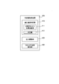
- FIG. 2 is a view showing a configuration example of the refrigerator control device shown in FIG. More specifically, FIG. 2 is a diagram showing each function realized by the CPU executing a predetermined program divided into blocks using hardware of the refrigerator control device 100.
- the refrigerator control device 100 includes a pressure reduction rate identification unit 110, a pressure adjustment unit 120, and a cold water outlet temperature setting unit 130.
- the pressure reduction rate specifying unit 110 includes a refrigerant deposition gas volume calculation unit 111 and a determination unit 112.
- the depressurization speed specifying unit 110 specifies the depressurization speed at which the forming does not occur in the oil tank 17.
- the pressure adjustment unit 120 adjusts the pressure of the evaporator 9 based on the pressure reduction rate identified by the pressure reduction rate identification unit 110.
- the pressure adjusting unit 120 adjusts the pressure of the evaporator 9 by, for example, controlling the expansion valve 7, the IGV 13, an HGBP (hot gas bypass) valve (not shown), and the like based on the cold water outlet temperature.
- the hot gas bypass valve is a valve for controlling the flow rate when leading a part of the compressed gas (hot gas) to the suction side.
- the refrigerant deposition gas volume calculation unit 111 of the pressure reduction rate specifying unit 110 calculates the volume of the refrigerant gas deposited from the lubricating oil when the pressure is reduced at a predetermined pressure reduction rate.
- the determination unit 112 determines whether or not the forming can be permitted based on the comparison between the calculated volume and the volume on the oil surface of the oil tank.
- the cold water outlet temperature setting unit 130 calculates the amount of decrease in evaporation temperature according to the specified decompression speed, and subtracts the amount of decrease in evaporation temperature from the set cold water outlet temperature, which is the target value of the current temperature of the cold water outlet 92 Value is set as the new set cold water outlet temperature.
- the pressure adjustment unit 120 adjusts the pressure of the evaporator 9 so that, for example, the measured value of the temperature of the cold water outlet 92 matches the set cold water outlet temperature set by the cold water outlet temperature setting unit 130.
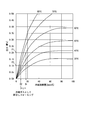
- refrigerant dissolution amount information regarding the refrigerant dissolution amount as shown in FIG. 5 is stored in a predetermined storage area in the storage device.
- the description format of the refrigerant dissolution amount information may be a map format, or may be a relational expression using an approximate expression or the like.
- the horizontal axis is the amount of dissolved refrigerant [mass (weight)%] indicating the amount of dissolution of the refrigerant into the lubricating oil
- the vertical axis is the pressure [MPa].
- Each curve shown in the figure indicates the refrigerant dissolution amount at each temperature (lubricant oil temperature).
- each curve has an upwardly convex shape, the lower the pressure, the smaller the amount of refrigerant dissolution, and the smaller the pressure, the larger the change in the amount of refrigerant dissolution.
- the higher the temperature the smaller the amount of refrigerant dissolution.
- the refrigerant dissolution amount changes from D1 to D2 when the measured value of the pressure sensor 25 changes from P1 to P2.
- the difference (D1-D2) of these is the amount of refrigerant leaching (the amount by which the refrigerant dissolved in the lubricating oil precipitates from the lubricating oil as a gas).
- the refrigerator control device 100 can calculate the amount of refrigerant leaching out based on the characteristics as shown in FIG.
- the lubricating oil When the refrigerant comes out of the lubricating oil as a gas, the lubricating oil may foam and the oil level rises, and the lubricating oil may fall (flow) from the oil tank 17 to the evaporator 9 through the pressure equalizing pipe 23 . In such a case, when lubricating oil adheres to the heat exchange tube of the evaporator 9, the performance (heat exchange amount) of the evaporator 9 is degraded. Further, since the refrigerant gas released from the lubricating oil is determined in accordance with the pressure difference generated within a predetermined time, when the pressure reduction rate is large, the oil level rises rapidly because it is released at once.
- the forming when determining whether or not the forming can be permitted based on the comparison between the volume of the refrigerant gas deposited from the lubricating oil and the volume on the oil surface of the oil tank 17 in the present embodiment. In addition, for example, it can be determined whether or not forming can be allowed under the following conditions.
- the determination unit 112 calculates the volume of the lubricating oil constantly present in the oil tank 17 (volume obtained by subtracting the amount of the lubricating oil circulating outside the oil tank 17 from the filling amount of the lubricating oil) If the sum of the volume of the refrigerant deposited from the oil and the volume of the refrigerant dissolved in the lubricating oil exceeds the volume of the oil tank 17, it can be determined that forming is not acceptable. In this case, in the determination by the determination unit 112, there is a possibility that the forming can not be permitted if the lubricating oil in the oil tank 17 may flow into the pressure equalizing pipe 23 due to the forming.
- both the condenser 5 and the evaporator 9 are in the state near the environmental temperature, and the pressure in the condenser 5 and the pressure in the evaporator 9 are substantially equal.
- the turbo refrigerator 1 is started in this state, the turbo compressor 3 is rotated by a command of the refrigerator control device 100, and the refrigerant sucked through the IGV 13 is discharged from the turbo compressor 3.
- the refrigerant discharged from the turbo compressor 3 is sent to the condenser 5, passes through the expansion valve 7 and the evaporator 9, and is circulated again to the turbo compressor 3.
- the turbo compressor 3 is gradually increased in speed according to a command from the refrigerator control device 100, and accordingly, the IGV 13 is also gradually controlled in the opening direction from the fully closed state.
- the refrigerant becomes a high-temperature high-pressure gas through the compressor 3 and enters the condenser 5.
- the refrigerant high temperature and high pressure gas
- the refrigerant is depressurized at once by the expansion valve 7, becomes a low pressure liquid, and is in a state of being easily evaporated.
- the evaporated low-pressure refrigerant gas becomes the high-temperature high-pressure gas again in the compressor 3.
- the evaporator 9 heat is exchanged between the refrigerant and the cold water.
- the cold water receives heat from the refrigerant in the evaporator 9 and is cooled to the target temperature ("set cold water outlet temperature").
- the evaporator 9 is on the "low pressure side" of the refrigeration cycle, and during operation, it is the place where the pressure of the refrigerant is the lowest.
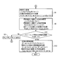
- FIG. 3:, FIG. 4 is FIG. 1, FIG. 2 which respectively shows the operation example of the refrigerator control apparatus shown in FIG.
- FIGS. 3 and 4 are flowcharts showing the flow of a series of processes, and the flow shown in FIG. 3 and the flow shown in FIG. 4 are connected to each other by the same connector A or B.
- the processes shown in FIGS. 3 and 4 are the process (steps S1 to S9 and S11) executed by the refrigerant gas volume calculation unit 111 shown in FIG.
- step S10 executed by the determination unit 112
- step S12 This is processing (step S12) executed by the setting unit 130.
- the pressure adjusting unit 120 adjusts the pressure of the evaporator 9 by feedback controlling the temperature of the cold water outlet 92 with the set cold water outlet temperature determined by the cold water outlet temperature setting unit 130 as a target value.
- the processes shown in FIG. 3 and FIG. 4 indicate that the chilled water outlet temperature command value (final target value of the set chilled water outlet temperature) and the current chilled water outlet temperature have a predetermined temperature difference while the turbo chiller 1 is running. If it is, it is repeatedly executed in a fixed cycle (for example, a cycle of several seconds to several tens of seconds).
- the refrigerant gas volume calculation unit 111 measures the evaporation pressure (measurement value before i seconds) Pe (tc-i) (i is an arbitrary positive number), the evaporation pressure. (Current measurement value) Pe (tc), oil tank temperature (current measurement value) Toil, cold water inlet temperature (current measurement value) TL1, and cold water flow rate (current measurement value) Fch are acquired (step S1).
- the evaporation pressure (measurement value before i seconds) Pe (tc-i) is a measurement value of i second before the pressure sensor 25.
- the refrigerant gas volume calculation unit 111 sequentially records the evaporation pressure (current measurement value) Pe (tc) in a predetermined storage area of the storage device (recording for at least one cycle of processing), for example. Pre-measurement value) The value stored as Pe (tc-i) is acquired.
- the evaporation pressure (current measurement value) Pe (tc) is a current measurement value of the pressure sensor 25.
- the oil tank temperature (current measurement value) Toil is a current measurement value of the temperature sensor 27.
- the chilled water inlet temperature (current measurement value) TL1 is a current measurement value of the temperature sensor 91T.
- the cold water flow rate (current measurement value) Fch is a current measurement value of the flow rate sensor 91F.
- the pressure of the evaporator 9, that is, the evaporation pressure is the same as the pressure of the oil tank 17 due to the communication effect of the equalizing pipe 23 as described above.
- the refrigerant gas volume calculation unit 111 sets the pressure change amount (decompression speed) Pe_r for i seconds to an initial value Pe_rset_down (step S2).
- the initial value Pe_rset_down is a negative value.
- the initial value Pe_rset_down is preset to correspond to the turbo refrigerator 1.
- the refrigerant gas volume calculation unit 111 obtains the pressure change amount Pe_r in which the forming does not occur.
- the larger the pressure change amount Pe_r the higher the possibility that forming can not be tolerated, but the followability to the target value of the chilled water outlet temperature can be improved. Therefore, it is desirable to set the initial value Pe_rset_down to a value near the boundary of whether or not forming can be permitted.
- the refrigerant gas volume calculation unit 111 calculates the evaporation pressure Pe (tc + i) after i seconds by adding the evaporation pressure (current measurement value) Pe (tc) and the pressure change amount Pe_r (step S3).
- the refrigerant gas volume calculation unit 111 obtains (or calculates) the following values from, for example, a predetermined storage area in the storage device of the refrigerator control device 100 (step S4). That is, in step S4, the refrigerant gas volume calculation unit 111 includes the lubricant property (refrigerant solubility) frefs, the lubricant property (density) foild, the refrigerant physical property (superheated gas density) frefdg, the refrigerant physical property (saturated liquid density) frefdl and the refrigerant Acquire physical property (saturation temperature) freft.
- the refrigerant gas volume calculation unit 111 includes the lubricant property (refrigerant solubility) frefs, the lubricant property (density) foild, the refrigerant physical property (superheated gas density) frefdg, the refrigerant physical property (saturated liquid density) frefdl and the refrig
- the refrigerant gas volume calculation unit 111 reduces the oil amount (the amount always in the oil tank 17) Voil from the oil charge (charged) amount Voilc to the oil amount (the amount always in the supply and discharge oil piping) Voils To calculate (step S5).
- the refrigerant gas volume calculation unit 111 calculates the current values of the refrigerant solubility, the lubricating oil density, the refrigerant dissolved mass, and the value after i seconds (step S6 and step S7).
- the refrigerant gas volume calculator 111 calculates the refrigerant solubility Sref (tc), the lubricant pressure corresponding to the evaporation pressure (current measurement value) Pe (tc), and the oil tank temperature (current measurement value) Toil. It is determined from the characteristic (refrigerant solubility) frefs.
- the lubricating oil characteristic (refrigerant solubility) frefs is a formula representing the characteristic of the graph shown in FIG.
- the refrigerant gas volume calculation unit 111 determines the lubricating oil density oiloil from the lubricating oil characteristic (density) foild corresponding to the oil tank temperature (current measurement value) Toil. In addition, the refrigerant gas volume calculation unit 111 calculates the refrigerant dissolution mass mrefs (tc) based on the amount of oil (which is always in the oil tank) Voil, the lubricating oil density oiloil, and the refrigerant solubility Sref (tc). It is determined from Voil / 10 ⁇ 3 ⁇ Sref (tc) / 100.
- step S7 the refrigerant gas volume calculation unit 111 performs lubrication corresponding to the refrigerant solubility Sref (tc + i) after i seconds, the evaporation pressure Pe (tc + i) after i seconds and the oil tank temperature (current measurement value) Toil. Determined from oil characteristics (refrigerant solubility) frefs. Further, the refrigerant gas volume calculation unit 111 determines the lubricating oil density oiloil after i seconds from the lubricating oil characteristic (density) foild corresponding to the oil tank temperature (currently measured value) Toil.
- the refrigerant gas volume calculation unit 111 determines the amount of refrigerant dissolution mrefs (tc + i) after i seconds, the amount of oil (a quantity always in the oil tank) Voil, the lubricating oil density ⁇ oil, and the refrigerant solubility Sref (tc + i after i seconds). And based on the equation ⁇ oil ⁇ Voil / 10 ⁇ 3 ⁇ Sref (tc + i) / 100.
- the refrigerant gas volume calculation unit 111 determines the refrigerant gas density refrefg and the refrigerant deposition gas volume Vrefd for i seconds as follows (step S8). That is, in step S8, the refrigerant gas volume calculation unit 111 determines the refrigerant gas density refrefg from the refrigerant physical property (superheated gas density) frefdg corresponding to the evaporation pressure Pe (tc + i) after i seconds.
- the refrigerant gas volume calculation unit 111 calculates the refrigerant deposition gas volume Vrefd for i seconds in the current refrigerant dissolved mass mrefs (tc) obtained in steps S6 to S8, and the refrigerant dissolved mass mrefs (tc + i) after i seconds and the refrigerant Based on the gas density refrefg, it is determined from the equation (mref (tc) ⁇ mref (tc + i)) / ⁇ refg ⁇ 10 3.
- the refrigerant gas volume calculation unit 111 calculates the refrigerant liquid density ref refl dissolved in the lubricating oil, the refrigerant liquid volume Vrefs dissolved in the lubricating oil, and the insufficient amount Vtank n of the space on the oil surface in the oil tank as follows. It determines (step S9). That is, in step S9, the refrigerant gas volume calculation unit 111 determines the refrigerant liquid density refrefl dissolved in the lubricating oil from the refrigerant physical property (saturated liquid density) frefdl (Toil) corresponding to the oil tank temperature (current measurement value) Toil. decide.
- the refrigerant gas volume calculation unit 111 uses the equation mrefs (ref: refrigerant melt mass mrefs (tc + i) after i seconds) and refrigerant liquid density refrefl dissolved in the lubricant after the refrigerant liquid volume Vrefs dissolved in the lubricant. It is determined from tc + i) / ⁇ refl.
- the refrigerant gas volume calculation unit 111 dissolves the insufficient amount Vtank_n of the space on the oil surface in the oil tank into the oil tank volume Vtank, the amount of oil (which is always in the oil tank) Voil, and the lubricating oil It is calculated from the following equation based on the refrigerant liquid volume Vrefs and the refrigerant deposition gas volume Vrefd for i seconds. That is, the refrigerant gas volume calculation unit 111 calculates the shortage Vtank_n of the space on the oil surface in the oil tank from the formula Vtank-Voil-Vrefs-Vrefd.
- step S10 determination unit 112 determines the possibility of the occurrence of forming.
- step S10 determination unit 112 determines that there is no possibility of forming when the shortage Vtank_n of the space above the oil surface in the oil tank is larger than 0 (Yes in step S10), and forming is less than 0 It is determined that there is a possibility of (No in step S10). If the determination unit 112 determines in step S10 that forming is likely to occur (No in step S10), the refrigerant gas volume calculation unit 111 reduces the absolute value of the pressure change amount Pe_r by a predetermined value (Pe_r_delta). Then (step S11), the processing after step S3 is executed again.
- the cold water outlet temperature setting unit 130 sets the set cold water outlet temperature TLO_rset (tc) as follows. It determines (step S12).
- the cold water outlet temperature setting unit 130 first determines the evaporation temperature ET_set (tc + i) after i seconds as follows. That is, the cold water outlet temperature setting unit 130 determines the evaporation temperature ET_set (tc + i) after i seconds from the refrigerant physical property (saturation temperature) freft corresponding to the evaporation pressure Pe (tc + i) after i seconds.
- the evaporation pressure and the evaporation temperature correspond uniquely. That is, the evaporation temperature of the refrigerant (the temperature at which the refrigerant evaporates) changes in one-to-one correspondence with the evaporation pressure of the refrigerant as a characteristic unique to the refrigerant.
- the cold water outlet temperature setting unit 130 calculates the evaporation temperature change amount ET_delta i seconds after the present by subtracting the evaporation temperature ET_set (tc + i) after i seconds from the current evaporation temperature ET_set (tc).
- the current evaporation temperature ET_set (tc) can be determined from the refrigerant physical property (saturation temperature) freft corresponding to the current evaporation pressure Pe (tc).
- the cold water outlet temperature setting unit 130 sets the set cold water outlet temperature (pressure change reference) TLO_rset (tc) as follows (step S12). That is, the chilled water outlet temperature setting unit 130 sets the set chilled water outlet temperature (pressure change reference) TLO_rset (tc) to the evaporation temperature change i seconds after the present from the previous set chilled water outlet temperature (pressure change reference) TLO_rset (tc + n) It can be calculated by subtracting the quantity ET_delta.
- the evaporation temperature of the refrigerant in the evaporator 9 directly corresponds to the temperature of the cold water (cold water outlet temperature).
- the evaporation pressure in the evaporator 9 is set to 0.2 MPa
- the evaporation temperature in the evaporator 9 is 23 ° C.
- the cold water outlet temperature is 20 ° C., etc. correspondingly.
- the evaporation pressure is reduced so that the evaporation temperature of the evaporator 9 changes from 23 ° C. to 20 ° C.
- the chilled water outlet temperature changes from 20 ° C. to 17 ° C. correspondingly.
- the refrigerator control device 100 controls the cold water outlet temperature by the pressure adjustment unit 120 based on the set cold water outlet temperature (pressure change reference) TLO_rset (tc) set in step S12.
- FIG. 6 is a diagram showing the result of confirming the operation example of the present embodiment.
- the horizontal axis is time
- the vertical axis is temperature
- the cold water outlet temperature setting unit 130 sets the final value of the set cold water outlet temperature to 5 ° C. after activating the turbo refrigerator 1.
- the set chilled water outlet temperature set by the chilled water outlet temperature setting unit 130 gradually changes with respect to the final value 5 ° C. of the set chilled water outlet temperature. That is, in the conventional refrigerator, control was performed to set 5 ° C. (final value) as the set chilled water outlet temperature immediately after startup, but the turbo chiller 1 according to the present embodiment has a set chilled water outlet temperature of 20 ° C, 18 ° C, ⁇ , gradually approach 5 ° C (final value).
- the refrigerator control device 100 controls the pressure of the evaporator 9 while estimating the state of forming in the oil tank 17. That is, the refrigerator control device 100 estimates how much refrigerant gas comes out when the pressure in the evaporator 9 is reduced, and changes the pressure reduction rate if the remainder of the oil tank 17 is zero. Then, the refrigerator control device 100 sets the set cold water outlet temperature (the target value of the cold water outlet temperature) according to the specified decompression speed, and performs temperature control of the cold water outlet temperature to reduce the pressure of the evaporator 9 Control the speed.
- the set chilled water outlet temperature is a set value of the desired chilled water temperature.
- the pressure adjusting unit 120 controls the pressure of the evaporator 9 by controlling the IGV 13 (vane), the expansion valve 7, the hot gas bypass valve, etc. in a balanced manner. Control (decompression) to control the actual cold water to match the target temperature (5.degree. C.). For example, when the set chilled water outlet temperature is suddenly set from 25 ° C. to 5 ° C., the pressure reduction rate in the evaporator 9 becomes steep and forming occurs. On the other hand, in the present embodiment, the setting value can be gradually approached from 25 ° C. to 5 ° C. at a speed at which forming does not occur.
- the pressure adjustment of the evaporator 9 is performed by controlling the IGV 13, the expansion valve 7, the hot gas bypass valve, etc. in cooperation within the feedback control of the cold water outlet temperature.
- the stability of control of the chilled water outlet temperature is not reduced as compared with the case where each single unit such as the valve 7 and the hot gas bypass valve is directly controlled.
- the refrigerant deposition gas volume calculation unit 111 that calculates the volume of the refrigerant gas that precipitates from the lubricating oil, the calculated volume, and the oil tank 17 Based on the comparison with the volume on the oil surface, the pressure reduction rate specifying unit 110 having the determination unit 112 that determines whether or not the forming can be permitted determines the pressure reduction rate Pe_r at which the forming does not occur in the oil tank 17. Then, the pressure adjusting unit 120 adjusts the pressure of the evaporator 9 based on the specified pressure reduction rate. Therefore, according to the present invention, the forming in the oil tank 17 can be more reliably suppressed.
- the present embodiment can be modified, for example, as follows.
- processing is added to change the evaporation pressure in the direction of pressurization instead of decompression.
- a process may be added to correct the set cold water outlet temperature to be lower than the cold water inlet temperature.
- a process of correcting the set chilled water outlet temperature may be added.
- the set chilled water outlet temperature (the change rate of the set cold chiller outlet temperature) does not satisfy the required specifications and the like of the turbo refrigerator 1, a process for correcting the set chilled water outlet temperature may be added.
- a turbo refrigerator according to a second embodiment will be described.
- the cold water is cooled to the set cold water outlet temperature by heat exchange (heat absorption) with the refrigerant in the evaporator 9 and the cold water is used for the cooling application to be circulated to the external load.
- the warm water is heated to a set warm water outlet temperature by heat exchange (heat release) with the refrigerant in the condenser 5 and used for a heating application in which this is circulated to an external load.
- the “cold water” circulating between the evaporator 9 and the external load (the object to be cooled) in the first embodiment is between the evaporator 9 and a predetermined heat source in the second embodiment. It corresponds to circulating "heat source water".
- the “cooling water” circulating between the condenser 9 and the cooling tower or the like in the first embodiment is between the condenser 9 and the external load (the object to be heated) in the second embodiment. Equivalent to "warm water” circulating
- the reduction rate of the set outlet chilled water temperature is adjusted so that the pressure reduction rate in the evaporator 9 is suppressed to such an extent that forming does not occur (see processing in step S12 of FIG. 4). ).
- the change amount of the setting outlet cold water temperature and the change amount of the evaporation temperature (evaporation pressure) in the evaporator 9 have a relation corresponding to one another to some extent.
- the change amount of the set outlet hot water temperature and the change amount of the condensation temperature (condensing pressure) in the condenser 5 are in a relation corresponding to one another to some extent.
- the relationship between the change amount of the set outlet hot water temperature and the change amount of the evaporation temperature (evaporation pressure) in the evaporator 9 is not limited to this. Therefore, the refrigerator control device 100 (hot water outlet temperature setting unit) according to the second embodiment performs the following process instead of step S12 in FIG. 4.
- the hot water outlet temperature setting unit of the refrigerator control device 100 first determines the evaporation temperature ET_set (tc + i) after i seconds as follows. That is, the hot water outlet temperature setting unit determines the evaporation temperature ET_set (tc + i) after i seconds from the refrigerant physical property (saturation temperature) freft corresponding to the evaporation pressure Pe (tc + i) after i seconds.
- the hot water outlet temperature setting unit calculates the evaporation temperature change amount ET_delta i seconds after the present by subtracting the evaporation temperature ET_set (tc + i) after i seconds from the current evaporation temperature ET_set (tc).
- the current evaporation temperature ET_set (tc) can be determined from the refrigerant physical property (saturation temperature) freft corresponding to the current evaporation pressure Pe (tc).
- the heat source water inlet temperature after i seconds can not be estimated. Therefore, here, the heat source water average temperature TLOave (tc + i) is estimated using the current heat source water inlet temperature TLI (current measurement value).
- the hot water outlet temperature setting unit obtains the specific heat Cwl [kcal / m3 ⁇ K] of the heat source water after i seconds from the following equation using the heat source water average temperature TLOave (tc + i) after i seconds.
- Cwl 0.000015878 x TLOave (tc + i) 3-0.005962 x TLO ave (tc + i) 2 + 0.022365 x TLO ave (tc + i) + 999.
- the warm water outlet temperature setting unit obtains the heat source water specific gravity ⁇ wl after i seconds from the following equation using the heat source water average temperature TLOave (tc + i) after i seconds.
- ⁇ wl ( ⁇ 0.00000045517) ⁇ TLOave (tc + i) 3 + 0.00010313 ⁇ TLOave (tc + i) 2 ⁇ 0.00058436 ⁇ TLOave (tc + i) +1.0075
- the hot water outlet temperature setting unit uses the specific heat Cwl of the heat source water after i seconds and the heat source water specific gravity ⁇ w after i seconds to set the refrigeration capacity Ql (tc + i) [kW] after i seconds in the evaporator 9 Calculated from the following equation.
- Fcl is the heat source water flow rate (currently measured value).
- Ql (tc + i) [TLI-TLO (tc + i)] ⁇ Fcl ⁇ Cwl ⁇ ⁇ wl / 3024 ⁇ 3.516
- the hot water outlet temperature setting unit calculates the heating capacity Qh (tc + i) [kW] in the condenser 5 by adding the inverter power consumption to the refrigeration capacity Ql (tc + i) in the evaporator 9.
- Pinv is inverter power consumption (currently measured value).
- Qh (tc + i) Ql (tc + i) + Pinv
- the warm water outlet temperature setting unit obtains the specific heat Cwh [kcal / m3 ⁇ K] of warm water after i seconds using the warm water average temperature THOave (tc + i) after i seconds according to the following equation.
- Cwh 0.000015878 x THOave (tc + i) 3-0.005962 x THOave (tc + i) 2 + 0.022365 x THOave (tc + i) + 999.96
- the warm water outlet temperature setting unit obtains the warm water specific gravity ⁇ wh after i seconds from the following equation using the warm water average temperature THOave (tc + i) after i seconds.
- ⁇ wh ( ⁇ 0.00000045517) ⁇ THOave (tc + i) 3 + 0.00010313 ⁇ THOave (tc + i) 2 ⁇ 0.000058436 ⁇ THOave (tc + i) +1.0075
- the hot water outlet temperature setting unit sets the set hot water outlet temperature THO_reset, the current value THI of the hot water inlet temperature, the heating capacity Qh (tc + i) after i seconds, the hot water flow rate Fch, and the specific heat of hot water after i seconds Using Cwh and the specific gravity ⁇ wh of warm water after i seconds, it is obtained from the following equation.
- the hot water outlet temperature setting unit adds the temperature difference that can be added to the hot water by the heating capacity Qh (tc + i) and the hot water flow rate Fch to the current value of the hot water inlet temperature. I am asking for THO_reset.
- THO_rset THI + Qh (tc + i) /3.516 ⁇ 3024/ (Fch ⁇ Cwh ⁇ ⁇ wh)
- the refrigerator control device 100 controls the hot water outlet temperature by the pressure adjustment unit 120 based on the set hot water outlet temperature (pressure change reference) THO_rset (tc) set in the above-described step.
- the refrigerator control device 100 (hot water outlet temperature setting unit) according to the second embodiment has the cooling capacity Ql (tc + i) obtained when the pressure is reduced at the pressure reduction rate at which forming does not occur. Calculate [kW]. Then, the refrigerator control device 100 is based on the premise that the cooling capacity on the evaporator 9 side and the heating capacity on the condenser 5 side become equal (however, in the above example, the inverter power consumption Pinv is added to the cooling capacity Ql ), The heating temperature Qh (tc + i) is obtained by the condenser 5 and the rising temperature of the hot water is calculated.
- the refrigerator control device 100 sets a value obtained by adding the calculation result of the rising temperature to the current hot water inlet temperature THI as a new set hot water outlet temperature THO_rset.
- the pressure adjusting unit 120 controls the condensing pressure in the condenser 5 so that the hot water outlet temperature (current measurement value) approaches the target value (set hot water outlet temperature THO_rset). The pressure reduction rate generated on the side is suppressed to the pressure reduction rate at which no forming occurs in the oil tank 17.
- the processes of various processes of the above-described refrigerator control device 100 are stored in the form of a program in a computer readable recording medium, and the computer reads and executes this program.
- the above-mentioned various processes are performed.
- the computer readable recording medium refers to a magnetic disk, a magneto-optical disk, a CD-ROM, a DVD-ROM, a semiconductor memory and the like.
- the computer program may be distributed to a computer through a communication line, and the computer that has received the distribution may execute the program.
- the program may be for realizing a part of the functions described above. Furthermore, it may be a so-called difference file (difference program) that can realize the above-described functions in combination with a program already recorded in the computer system. Furthermore, the refrigerator control device 100 may be configured by one computer, or may be configured by a plurality of computers communicably connected.
Landscapes
- Engineering & Computer Science (AREA)
- Physics & Mathematics (AREA)
- Mechanical Engineering (AREA)
- Thermal Sciences (AREA)
- General Engineering & Computer Science (AREA)
- Structures Of Non-Positive Displacement Pumps (AREA)
- Control Of Positive-Displacement Air Blowers (AREA)
Abstract
本実施形態の冷凍機制御装置は、ターボ冷凍機を制御する装置であって、油タンクにおいてフォーミングが起きない減圧速度を特定する減圧速度特定部と、特定された減圧速度に基づいて蒸発器の圧力を調整する圧力調整部と、を備え、減圧速度特定部は、所定の減圧速度で減圧した場合に、潤滑油から析出する冷媒ガスの体積を演算する冷媒析出ガス体積演算部と、演算された体積と、油タンクの油面上の体積との対比に基づいて、フォーミングを許容できるか否かを判定する判定部とを備える。
Description
本発明は、冷凍機制御装置、ターボ冷凍機、冷凍機制御方法およびプログラムに関する。
本願は、2017年3月31日に日本に出願された特願2017-070049号について優先権を主張し、その内容をここに援用する。
本願は、2017年3月31日に日本に出願された特願2017-070049号について優先権を主張し、その内容をここに援用する。
従来、ターボ冷凍機に使用しているHFC(代替フロン)冷媒は、GWP(Global Warming Potential:地球温暖化係数)が数百~数千であり、環境への配慮からGWPが1桁のHFO冷媒への転換が必要である。これに対応するため、燃焼性のないHFO-1233zd(E)といった低圧冷媒をチラー用冷媒とすることがある。ターボ冷凍機は、一般に、ターボ圧縮機に供給する潤滑油が貯留された油タンクを備えている。ここで、FO-1233zd(E)の冷媒ガスの比体積は、HFC-134aの約5倍である。そのため、低圧冷媒を用いた冷凍機では、油タンク内の圧力が大気圧以下になると、ガス体積が大きくなる。つまり、低圧冷媒を用いた冷凍機では、油タンク内の潤滑油に溶け込んでいた同質量の冷媒が圧力低下して蒸発した場合、高圧冷媒を用いた冷凍機と比較して、蒸発する冷媒の体積が大きくなり、油タンクの潤滑油に泡立ちが生じるフォーミングが発生しやすくなる。特に、低圧側の圧力低下速度が大きい起動時は、油タンク内の潤滑油にフォーミングが発生しやすい。
特許文献1には、ターボ圧縮機を起動させるときに、吸入容量制御部の開度を目標開度よりも小さな開度で起動した後、速やかに目標開度まで開けることで、目標開度未満である運転時間をできるだけ短くして冷媒の通過抵抗を小さくし、吸入容量制御部の下流側の圧力低下を抑制することによってフォーミングの発生を抑えることが開示されている。
しかし、同じ圧力低下速度でも圧力の値によって潤滑油に対する冷媒溶解量は異なるので、潤滑油からの冷媒溶け出し量は、油タンク内の圧力によって異なる。また、潤滑油に対する冷媒溶解量は温度にも依存する。したがって、油タンク内のフォーミングをより確実に抑制することが求められる。
本発明の目的は、油タンク内のフォーミングをより確実に抑制することができる冷凍機制御装置、ターボ冷凍機、冷凍機制御方法およびプログラムを提供することにある。
本発明の第1の態様によれば、冷媒ガスを圧縮するターボ圧縮機と、前記ターボ圧縮機によって圧縮された冷媒ガスを熱交換により放熱させて凝縮させる凝縮器と、前記凝縮器から導かれた液冷媒を膨張させる膨張弁と、前記膨張弁によって膨張された液冷媒を熱交換により吸熱させて蒸発させることで冷水入口から流入させた冷水の温度を低下させて冷水出口から流出させる蒸発器と、前記ターボ圧縮機に供給する潤滑油を貯留する油タンクと、前記油タンクと前記蒸発器とを接続する均圧管と、を備えたターボ冷凍機を制御する装置であって、前記油タンクにおいてフォーミングが起きない減圧速度を特定する減圧速度特定部と、特定された前記減圧速度に基づいて前記蒸発器の圧力を調整する圧力調整部と、を備え、前記減圧速度特定部は、所定の減圧速度で減圧した場合に、前記潤滑油から析出する冷媒ガスの体積を演算する冷媒析出ガス体積演算部と、演算された前記体積と、前記油タンクの油面上の体積との対比に基づいて、前記フォーミングを許容できるか否かを判定する判定部と、を備える冷凍機制御装置である。
本発明の第2の態様によれば、上記冷凍機制御装置であって、特定された前記減圧速度に応じた蒸発温度の低下量を算出するとともに、現在の前記冷水出口の温度の目標値である設定冷水出口温度から前記蒸発温度の低下量を差し引いた値を新たな設定冷水出口温度として設定する冷水出口温度設定部を更に備え、前記圧力調整部は、前記冷水出口の温度の計測値が、前記冷水出口温度設定部によって設定された設定冷水出口温度と一致するように前記蒸発器の圧力を調整する。
本発明の第3の態様によれば、冷媒ガスを圧縮するターボ圧縮機と、前記ターボ圧縮機によって圧縮された冷媒ガスを熱交換により放熱させて凝縮させる凝縮器と、前記凝縮器から導かれた液冷媒を膨張させる膨張弁と、前記膨張弁によって膨張された液冷媒を熱交換により吸熱させて蒸発させることで冷水入口から流入させた冷水の温度を低下させて冷水出口から流出させる蒸発器と、前記ターボ圧縮機に供給する潤滑油を貯留する油タンクと、前記油タンクと前記蒸発器とを接続する均圧管と、各部を制御する冷凍機制御装置とを備え、前記冷凍機制御装置は、前記油タンクにおいてフォーミングが起きない減圧速度を特定する減圧速度特定部と、特定された前記減圧速度に基づいて前記蒸発器の圧力を調整する圧力調整部と、を有し、前記減圧速度特定部は、所定の減圧速度で減圧した場合に、前記潤滑油から析出する冷媒ガスの体積を演算する冷媒析出ガス体積演算部と、演算された前記体積と、前記油タンクの油面上の体積との対比に基づいて、前記フォーミングを許容できるか否かを判定する判定部と、を有するターボ冷凍機である。
本発明の第4の態様によれば、冷媒ガスを圧縮するターボ圧縮機と、前記ターボ圧縮機によって圧縮された冷媒ガスを熱交換により放熱させて凝縮させる凝縮器と、前記凝縮器から導かれた液冷媒を膨張させる膨張弁と、前記膨張弁によって膨張された液冷媒を熱交換により吸熱させて蒸発させることで冷水入口から流入させた冷水の温度を低下させて冷水出口から流出させる蒸発器と、前記ターボ圧縮機に供給する潤滑油を貯留する油タンクと、前記油タンクと前記蒸発器とを接続する均圧管と、を備えたターボ冷凍機を冷凍機制御装置によって制御する方法であって、前記冷凍機制御装置は、前記油タンクにおいてフォーミングが起きない減圧速度を特定する減圧速度特定部と、特定された前記減圧速度に基づいて前記蒸発器の圧力を調整する圧力調整部と、を有し、前記減圧速度特定部は、冷媒析出ガス体積演算部と、判定部とを有し、前記冷媒析出ガス体積演算部によって、所定の減圧速度で減圧した場合に、前記潤滑油から析出する冷媒ガスの体積を演算し、前記判定部によって、演算された前記体積と、前記油タンクの油面上の体積との対比に基づいて、前記フォーミングを許容できるか否かを判定する冷凍機制御方法である。
本発明の第5の態様によれば、冷媒ガスを圧縮するターボ圧縮機と、前記ターボ圧縮機によって圧縮された冷媒ガスを熱交換により放熱させて凝縮させる凝縮器と、前記凝縮器から導かれた液冷媒を膨張させる膨張弁と、前記膨張弁によって膨張された液冷媒を熱交換により吸熱させて蒸発させることで冷水入口から流入させた冷水の温度を低下させて冷水出口から流出させる蒸発器と、前記ターボ圧縮機に供給する潤滑油を貯留する油タンクと、前記油タンクと前記蒸発器とを接続する均圧管と、を備えたターボ冷凍機を冷凍機制御装置によって制御するためのプログラムであって、前記冷凍機制御装置は、前記油タンクにおいてフォーミングが起きない減圧速度を特定する減圧速度特定部と、特定された前記減圧速度に基づいて前記蒸発器の圧力を調整する圧力調整部と、を有し、前記減圧速度特定部は、冷媒析出ガス体積演算部と、判定部とを有し、前記冷媒析出ガス体積演算部によって。所定の減圧速度で減圧した場合に、前記潤滑油から析出する冷媒ガスの体積を演算させ、前記判定部によって、演算された前記体積と、前記油タンクの油面上の体積との対比に基づいて、前記フォーミングを許容できるか否かを判定させるプログラムである。
上述の本発明の態様によれば、油タンク内のフォーミングをより確実に抑制することができる。
<第1の実施形態>
以下、第1の実施形態に係るターボ冷凍機について、図1~図6を参照しながら説明する。
以下、第1の実施形態に係るターボ冷凍機について、図1~図6を参照しながら説明する。
(ターボ冷凍機の全体構成)
図1は、第1の実施形態に係るターボ冷凍機の全体構成を示す図である。
図1に示すように、ターボ冷凍機1は、ターボ圧縮機3と、凝縮器5と、膨張弁7と、蒸発器9と、冷凍機制御装置100を備えている。ターボ圧縮機3は、冷媒を圧縮する。
凝縮器5は、ターボ圧縮機3によって圧縮された高温高圧のガス冷媒を凝縮する。膨張弁7は、凝縮器5から導かれた液冷媒を膨張させる。蒸発器9は、膨張弁7によって膨張された液冷媒を蒸発させる。冷凍機制御装置100は、ターボ圧縮機3、凝縮器5、膨張弁7、蒸発器9等の各部を制御する。ターボ冷凍機1で用いられる冷媒は、例えば、HFO-1233zd(E)等の低圧冷媒とすることができるが、これに限定されない。
図1は、第1の実施形態に係るターボ冷凍機の全体構成を示す図である。
図1に示すように、ターボ冷凍機1は、ターボ圧縮機3と、凝縮器5と、膨張弁7と、蒸発器9と、冷凍機制御装置100を備えている。ターボ圧縮機3は、冷媒を圧縮する。
凝縮器5は、ターボ圧縮機3によって圧縮された高温高圧のガス冷媒を凝縮する。膨張弁7は、凝縮器5から導かれた液冷媒を膨張させる。蒸発器9は、膨張弁7によって膨張された液冷媒を蒸発させる。冷凍機制御装置100は、ターボ圧縮機3、凝縮器5、膨張弁7、蒸発器9等の各部を制御する。ターボ冷凍機1で用いられる冷媒は、例えば、HFO-1233zd(E)等の低圧冷媒とすることができるが、これに限定されない。
ターボ圧縮機3は、遠心式圧縮機であり、図示していないインバータによって回転数制御された電動機11によって駆動される。インバータは、冷凍機制御装置100によってその出力が制御される。ターボ圧縮機3の冷媒吸入口には、吸入冷媒流量を制御するインレットガイドベーン(以下「IGV」という。)13が設けられており、ターボ冷凍機1の容量制御が可能である。IGV13の開度制御は、冷凍機制御装置100によって行われる。
ターボ圧縮機3は、回転軸3b周りに回転する羽根車3aを備えている。回転軸3bには、増速歯車15を介して電動機11から回転動力が伝達される。回転軸3bは、軸受3cによって支持されている。なお、他の実施形態に係るターボ圧縮機3は、このような増速歯車15を具備しない態様(例えば、電動機直結型)であってもよい。
凝縮器5は、ターボ圧縮機3によって圧縮された冷媒ガスを、冷却水との熱交換により放熱させて凝縮させる。凝縮器5は、例えばシェルアンドチューブ型やプレート型等の熱交換器とすることができる。凝縮器5には、冷媒を冷却するための冷却水が供給される。
凝縮器5に導かれる冷却水は、図示しない冷却塔や空気熱交換器において外部へと排熱された後に、再び凝縮器5へと導かれる。
凝縮器5に導かれる冷却水は、図示しない冷却塔や空気熱交換器において外部へと排熱された後に、再び凝縮器5へと導かれる。
膨張弁7は、例えば電動式であり、冷凍機制御装置100によって開度が任意に設定される。
蒸発器9は、例えばシェルアンドチューブ型やプレート型等の熱交換器とすることができる。蒸発器9は、膨張弁7によって膨張された液冷媒を、冷水との熱交換により蒸発させることで冷水入口91から流入させた冷水の温度を低下させて冷水出口92から流出させる。冷水出口92から流出した冷水は、図示しない外部負荷へ供給される。冷水は、蒸発器9にて冷媒と熱交換することで、定格温度(例えば7℃)まで冷却され、外部負荷へと送られる。
冷水入口91には、温度センサ91Tと流量センサ91Fとが設けられている。温度センサ91Tは、冷水入口91における冷水温度(冷水入口温度)を計測し、冷凍機制御装置100へ計測結果を出力する。流量センサ91Fは、冷水入口91における冷水流量を計測し、冷凍機制御装置100へ計測結果を出力する。冷水出口92には、温度センサ92Tが設けられている。温度センサ92Tは、冷水出口92における冷水温度(冷水出口温度)を計測し、冷凍機制御装置100へ計測結果を出力する。
ターボ圧縮機3の軸受3cや増速歯車15へは、油タンク17から潤滑油が供給される。潤滑油としては、例えば、鉱物油が用いられる。油タンク17内には、図示しない油ポンプが設けられており、これにより、所定の流量にて油供給配管19を介して潤滑油が供給される。ターボ圧縮機3内で潤滑を終えた潤滑油は、油返送配管21を介して油タンク17内へと戻される。
油タンク17と蒸発器9との間には、これらの間を連通する均圧管23が設けられている。均圧管23によって、油タンク17内の圧力と蒸発器9内の圧力が均圧される。このように油タンク17内を低圧にすることで、潤滑油に対する冷媒溶け込み量が低く保たれる。
油タンク17には、圧力センサ25と温度センサ27が設けられている。圧力センサ25は、油タンク17内の圧力を計測し、冷凍機制御装置100へ計測結果を出力する。温度センサ27は、油タンク17内の温度(具体的には例えば潤滑油温度)を計測し、冷凍機制御装置100へ計測結果を出力する。
冷凍機制御装置100は、ターボ冷凍機1の圧力制御、温度制御等のターボ冷凍機1の運転に関する制御を行う。冷凍機制御装置100は、例えば、CPU(中央処理装置)、揮発性および不揮発性の記憶装置、入出力装置、通信装置等から構成されている。そして、各種機能を実現するための一連の処理は、一例として、プログラムの形式で不揮発性の記憶装置等に記憶されており、このプログラムをCPUが揮発性の記憶装置等に読み出して、情報の加工・演算処理を実行することにより、各種機能が実現される。
(冷凍機制御装置の構成例)
図2は、図1に示す冷凍機制御装置の構成例を示す図である。
より具体的には、図2は、冷凍機制御装置100が有するハードウェアを利用し、所定のプログラムをCPUが実行することで実現される各機能をブロックに分けて示す図である。
冷凍機制御装置100は、図2に示すように、減圧速度特定部110、圧力調整部120、および冷水出口温度設定部130を備える。また、減圧速度特定部110は、冷媒析出ガス体積演算部111と判定部112を備える。
図2は、図1に示す冷凍機制御装置の構成例を示す図である。
より具体的には、図2は、冷凍機制御装置100が有するハードウェアを利用し、所定のプログラムをCPUが実行することで実現される各機能をブロックに分けて示す図である。
冷凍機制御装置100は、図2に示すように、減圧速度特定部110、圧力調整部120、および冷水出口温度設定部130を備える。また、減圧速度特定部110は、冷媒析出ガス体積演算部111と判定部112を備える。
減圧速度特定部110は、油タンク17においてフォーミングが起きない減圧速度を特定する。圧力調整部120は、減圧速度特定部110によって特定された減圧速度に基づいて蒸発器9の圧力を調整する。圧力調整部120は、例えば、上記冷水出口温度に基づき、膨張弁7、IGV13や図示していないHGBP(ホットガスバイパス)弁等を制御することで蒸発器9の圧力を調整する。ここで、ホットガスバイパス弁とは、圧縮ガス(ホットガス)の一部を吸い込み側に導く際の流量を制御する弁である。減圧速度特定部110が有する冷媒析出ガス体積演算部111は、所定の減圧速度で減圧した場合に、潤滑油から析出する冷媒ガスの体積を演算する。判定部112は、演算された体積と、油タンクの油面上の体積との対比に基づいて、フォーミングを許容できるか否かを判定する。冷水出口温度設定部130は、特定された減圧速度に応じた蒸発温度の低下量を算出するとともに、現在の冷水出口92の温度の目標値である設定冷水出口温度から蒸発温度の低下量を差し引いた値を新たな設定冷水出口温度として設定する。圧力調整部120は、例えば冷水出口92の温度の計測値が、冷水出口温度設定部130によって設定された設定冷水出口温度と一致するように蒸発器9の圧力を調整する。
また、冷凍機制御装置100には、図5に示すような冷媒溶解量に関する冷媒溶解量情報が記憶装置内の所定の記憶領域に格納されている。なお、この冷媒溶解量情報の記述形式は、マップ形式でもよいし、近似式等を用いた関係式としてもよい。
図5において、横軸は、潤滑油に対する冷媒の溶け込み量を示す冷媒溶解量[mass(重量)%]であり、縦軸は圧力[MPa]である。同図中に示された各曲線は、それぞれの温度(潤滑油温度)における冷媒溶解量を示している。同図から分かるように、各曲線は上に凸の形状とされており、圧力が低いほど冷媒溶解量が小さく、また圧力が低い領域ほど冷媒溶解量の変化が大きい。さらに、同じ圧力で比較した場合、温度が高いほど冷媒溶解量が小さいことが分かる。
図5に示す特性では、例えば、温度センサ27で計測した油タンク17内の温度が60℃の場合、圧力センサ25の計測値がP1からP2に変化したとき、冷媒溶解量はD1からD2に変化する。この場合、これらの差分(D1-D2)が、冷媒溶け出し量(潤滑油に溶け込んでいる冷媒がガスとして潤滑油から析出する量)となる。冷凍機制御装置100は、図5に示すような特性に基づいて冷媒溶け出し量を演算することができる。なお、潤滑油から冷媒がガスとして出てきた場合、潤滑油が泡状となって油面が上昇し、油タンク17から均圧管23を通じて蒸発器9に潤滑油が落ちる(流れる)ときがある。このような場合に蒸発器9の熱交換用のチューブに潤滑油がついてしまったときには、蒸発器9の性能(熱交換量)が落ちてしまうことになる。また、潤滑油から放出される冷媒ガスは、一定時間内に生じる圧力差に応じて決まるため、減圧速度が大きい場合、一気に放出されるため油面は急上昇する。なお、本実施形態において、判定部112は、潤滑油から析出する冷媒ガスの体積と、油タンク17の油面上の体積との対比に基づいて、フォーミングを許容できるか否かを判定する際に、例えば、次の条件でフォーミングを許容できるか否かを判定することができる。すなわち、判定部112は、油タンク17に定常的に存在する潤滑油の体積(潤滑油の充填量から油タンク17外で循環している潤滑油の量を差し引いた分の体積)と、潤滑油から析出する冷媒の体積と、潤滑油に熔解している冷媒の体積の合計が、油タンク17の体積を越える場合を、フォーミングを許容できない場合であると判定することができる。この場合、判定部112による判定では、フォーミングによって油タンク17内の潤滑油が均圧管23内に流入する可能性がある場合を、フォーミングを許容できない可能性がある場合としていることになる。
(動作例)
次に、上記構成のターボ冷凍機1の基本的な動作について説明する。ターボ冷凍機1の起動前は、凝縮器5および蒸発器9ともに環境温度近くの状態であり、凝縮器5内の圧力と蒸発器9内の圧力は略同等である。この状態でターボ冷凍機1を起動すると、冷凍機制御装置100の指令により、ターボ圧縮機3が回転し、IGV13を介して吸い込んだ冷媒がターボ圧縮機3から吐出される。ターボ圧縮機3から吐出された冷媒は、凝縮器5へと送られて、膨張弁7および蒸発器9を通り再びターボ圧縮機3へと戻り循環する。ターボ圧縮機3は、冷凍機制御装置100の指令によって徐々に昇速されていき、これに伴いIGV13も、全閉とされた状態から徐々に開方向に制御されていく。
次に、上記構成のターボ冷凍機1の基本的な動作について説明する。ターボ冷凍機1の起動前は、凝縮器5および蒸発器9ともに環境温度近くの状態であり、凝縮器5内の圧力と蒸発器9内の圧力は略同等である。この状態でターボ冷凍機1を起動すると、冷凍機制御装置100の指令により、ターボ圧縮機3が回転し、IGV13を介して吸い込んだ冷媒がターボ圧縮機3から吐出される。ターボ圧縮機3から吐出された冷媒は、凝縮器5へと送られて、膨張弁7および蒸発器9を通り再びターボ圧縮機3へと戻り循環する。ターボ圧縮機3は、冷凍機制御装置100の指令によって徐々に昇速されていき、これに伴いIGV13も、全閉とされた状態から徐々に開方向に制御されていく。
ターボ冷凍機1において、冷媒は、圧縮機3を通じて高温高圧ガスとなり、凝縮器5に入る。凝縮器5では、冷媒(高温高圧ガス)は熱を奪われ、高圧の液体になる。次に、冷媒は、膨張弁7により一気に減圧され、低圧の液体となり、蒸発しやすい状態となる。膨張弁7を通じて低圧化された液体冷媒が蒸発器9に入って流入した冷水から熱をもらい、蒸発する。蒸発した低圧冷媒ガスは、圧縮機3で再び高温高圧ガスとなる。以上の冷凍サイクルにおいて、蒸発器9では、冷媒と冷水との間で熱のやり取りがなされる。冷水は、蒸発器9で冷媒に熱を奪われて、目的の温度(「設定冷水出口温度」)に冷やされる。また、蒸発器9は、冷凍サイクルの「低圧側」であり、運転中は、冷媒の圧力が最も低い箇所となる。
(処理フロー)
図3、図4は、それぞれ、図1に示す冷凍機制御装置の動作例を示す第1図、第2図である。
次に、図3および図4を参照して、図1に示す冷凍機制御装置100の動作例について説明する。図3および図4は、一連の処理の流れを示すフローチャートであり、図3に示すフローと図4に示すフローは同一の結合子AまたはBで互いに結合されている。図3および図4に示す処理は、図2に示す冷媒ガス体積演算部111が実行する処理(ステップS1~S9およびS11)と、判定部112が実行する処理(ステップS10)と、冷水出口温度設定部130が実行する処理(ステップS12)である。冷凍機制御装置100において圧力調整部120は、冷水出口温度設定部130が決定した設定冷水出口温度を目標値とし、冷水出口92の温度をフィードバック制御することで蒸発器9の圧力を調整する。図3および図4に示す処理は、ターボ冷凍機1が起動中、冷水出口温度の指令値(設定冷水出口温度の最終的な目標値)と、現在の冷水出口温度が所定の温度差を有している場合に、一定の周期(例えば数秒~数十秒周期)で繰り返し実行される。
図3、図4は、それぞれ、図1に示す冷凍機制御装置の動作例を示す第1図、第2図である。
次に、図3および図4を参照して、図1に示す冷凍機制御装置100の動作例について説明する。図3および図4は、一連の処理の流れを示すフローチャートであり、図3に示すフローと図4に示すフローは同一の結合子AまたはBで互いに結合されている。図3および図4に示す処理は、図2に示す冷媒ガス体積演算部111が実行する処理(ステップS1~S9およびS11)と、判定部112が実行する処理(ステップS10)と、冷水出口温度設定部130が実行する処理(ステップS12)である。冷凍機制御装置100において圧力調整部120は、冷水出口温度設定部130が決定した設定冷水出口温度を目標値とし、冷水出口92の温度をフィードバック制御することで蒸発器9の圧力を調整する。図3および図4に示す処理は、ターボ冷凍機1が起動中、冷水出口温度の指令値(設定冷水出口温度の最終的な目標値)と、現在の冷水出口温度が所定の温度差を有している場合に、一定の周期(例えば数秒~数十秒周期)で繰り返し実行される。
図3および図4に示す処理は、まず、冷媒ガス体積演算部111が、蒸発圧力(i秒前計測値)Pe(tc-i)(iは任意の正の数である。)、蒸発圧力(現在計測値)Pe(tc)、油タンク温度(現在計測値)Toil、冷水入口温度(現在計測値)TL1、および冷水流量(現在計測値)Fchを取得する(ステップS1)。蒸発圧力(i秒前計測値)Pe(tc-i)は、圧力センサ25のi秒前の計測値である。冷媒ガス体積演算部111は、蒸発圧力(現在計測値)Pe(tc)を例えば記憶装置内の所定の記憶領域に逐次記録(少なくとも処理の1周期分記録)しておき、蒸発圧力(i秒前計測値)Pe(tc-i)として記憶したおいた値を取得する。蒸発圧力(現在計測値)Pe(tc)は、圧力センサ25の現在の計測値である。油タンク温度(現在計測値)Toilは、温度センサ27の現在の計測値である。冷水入口温度(現在計測値)TL1は、温度センサ91Tの現在の計測値である。冷水流量(現在計測値)Fchは、流量センサ91Fの現在の計測値である。なお、蒸発器9の圧力すなわち蒸発圧力は、上述したように均等管23の連通効果によって油タンク17の圧力と同一である。
次に冷媒ガス体積演算部111は、i秒間の圧力変化量(減圧速度)Pe_rを初期値Pe_rset_downに設定する(ステップS2)。なお、初期値Pe_rset_downは負の値である。初期値Pe_rset_downは、ターボ冷凍機1に対応するように予め設定する。冷媒ガス体積演算部111は、この初期値Pe_rset_downから圧力変化量Pe_rを所定量Pe_r_deltaずつ変化させながら(ステップS11)、フォーミングが起きない圧力変化量Pe_rを求める。圧力変化量Pe_rが大きいほど、フォーミングを許容できない可能性は高くなるものの、冷水出口温度の目標値に対する追従性を高めることができる。したがって、初期値Pe_rset_downは、フォーミングを許容できるか否かの境界付近の値に設定することが望ましい。
次に冷媒ガス体積演算部111は、蒸発圧力(現在計測値)Pe(tc)と圧力変化量Pe_rを加算することでi秒後の蒸発圧力Pe(tc+i)を算出する(ステップS3)。
次に冷媒ガス体積演算部111は、例えば冷凍機制御装置100が有する記憶装置内の所定の記憶領域から、次の各値を取得(あるいは算出)する(ステップS4)。すなわち、ステップS4において、冷媒ガス体積演算部111は、潤滑油特性(冷媒溶解度)frefs、潤滑油特性(密度)foild、冷媒物性(過熱ガス密度)frefdg、冷媒物性(飽和液密度)frefdlおよび冷媒物性(飽和温度)freftを取得する。
次に冷媒ガス体積演算部111は、油量(油タンク17内に常時ある量)Voilを、油充填(チャージ)量Voilcから油量(給排油配管内に常時ある量)Voilsを減じることで算出する(ステップS5)。
次に冷媒ガス体積演算部111は、冷媒溶解度と潤滑油密度と冷媒溶解質量の現在値とi秒後の値を算出する(ステップS6およびステップS7)。ステップS6において、現在値について、冷媒ガス体積演算部111は、冷媒溶解度Sref(tc)を、蒸発圧力(現在計測値)Pe(tc)と油タンク温度(現在計測値)Toilに対応する潤滑油特性(冷媒溶解度)frefsから決定する。ここで、潤滑油特性(冷媒溶解度)frefsは、図5に示すグラフの特性を表す式である。また、冷媒ガス体積演算部111は、潤滑油密度ρoilを油タンク温度(現在計測値)Toilに対応する潤滑油特性(密度)foildから決定する。また、冷媒ガス体積演算部111は、冷媒溶解質量mrefs(tc)を、油量(油タンク内に常時ある量)Voilと潤滑油密度ρoilと冷媒溶解度Sref(tc)とに基づき、式ρoil×Voil/10^3×Sref(tc)/100から決定する。
一方、ステップS7において、冷媒ガス体積演算部111は、i秒後の冷媒溶解度Sref(tc+i)を、i秒後の蒸発圧力Pe(tc+i)と油タンク温度(現在計測値)Toilに対応する潤滑油特性(冷媒溶解度)frefsから決定する。また、冷媒ガス体積演算部111は、i秒後の潤滑油密度ρoilを油タンク温度(現在計測値)Toilに対応する潤滑油特性(密度)foildから決定する。また、冷媒ガス体積演算部111は、i秒後の冷媒溶解質量mrefs(tc+i)を、油量(油タンク内に常時ある量)Voilと潤滑油密度ρoilとi秒後の冷媒溶解度Sref(tc+i)とに基づき、式ρoil×Voil/10^3×Sref(tc+i)/100から決定する。
次に、冷媒ガス体積演算部111は、冷媒ガス密度ρrefgとi秒間の冷媒析出ガス体積Vrefdを次のように決定する(ステップS8)。すなわち、ステップS8において、冷媒ガス体積演算部111は、冷媒ガス密度ρrefgを、i秒後の蒸発圧力Pe(tc+i)に対応する冷媒物性(過熱ガス密度)frefdgから決定する。また、冷媒ガス体積演算部111は、i秒間の冷媒析出ガス体積Vrefdを、ステップS6~S8で求めた現在の冷媒溶解質量mrefs(tc)とi秒後の冷媒溶解質量mrefs(tc+i)と冷媒ガス密度ρrefgとに基づき、式(mref(tc)-mref(tc+i))/ρrefg×10^3から決定する。
次に、冷媒ガス体積演算部111は、潤滑油内に溶解する冷媒液密度ρreflと潤滑油内に溶解する冷媒液体積Vrefsと油タンク内油面上の空間の不足量Vtank_nを次のように決定する(ステップS9)。すなわち、ステップS9において、冷媒ガス体積演算部111は、潤滑油内に溶解する冷媒液密度ρreflを、油タンク温度(現在計測値)Toilに対応する冷媒物性(飽和液密度)frefdl(Toil)から決定する。また、冷媒ガス体積演算部111は、潤滑油内に溶解する冷媒液体積Vrefsを、i秒後の冷媒溶解質量mrefs(tc+i)と潤滑油内に溶解する冷媒液密度ρreflに基づき、式mrefs(tc+i)/ρreflから決定する。また、冷媒ガス体積演算部111は、油タンク内油面上の空間の不足量Vtank_nを、油タンク容積Vtankと、油量(油タンク内に常時ある量)Voilと、潤滑油内に溶解する冷媒液体積Vrefsと、i秒間の冷媒析出ガス体積Vrefdに基づき、次式から算出する。すなわち、冷媒ガス体積演算部111は、油タンク内油面上の空間の不足量Vtank_nを、式Vtank-Voil-Vrefs-Vrefdから算出する。
次に、判定部112は、フォーミング発生の可能性を判断する(ステップS10)。ステップS10において、判定部112は、油タンク内油面上の空間の不足量Vtank_nが0より大きい場合にフォーミング発生の可能性なしと判断し(ステップS10でYes)、0以下の場合にフォーミング発生の可能性ありと判断する(ステップS10でNo)。ステップS10で判定部112がフォーミング発生の可能性ありと判断した場合(ステップS10でNoの場合)、冷媒ガス体積演算部111は、圧力変化量Pe_rの絶対値を所定の値(Pe_r_delta)だけ小さくし(ステップS11)、ステップS3以降の処理を再度実行する。一方、ステップS10で判定部112がフォーミング発生の可能性なしと判断した場合(ステップS10でYesの場合)、冷水出口温度設定部130が、以下のようにして設定冷水出口温度TLO_rset(tc)を決定する(ステップS12)。
すなわち、ステップS12において、冷水出口温度設定部130は、まず、i秒後の蒸発温度ET_set(tc+i)を次のように決定する。すなわち、冷水出口温度設定部130は、i秒後の蒸発温度ET_set(tc+i)を、i秒後の蒸発圧力Pe(tc+i)に対応する冷媒物性(飽和温度)freftから決定する。なお、蒸発圧力と蒸発温度は一意に対応する。すなわち、冷媒の蒸発温度(冷媒が蒸発する温度)は、その冷媒固有の特性として、冷媒の蒸発圧力と一対一で対応して変化する。
次に、冷水出口温度設定部130は、現在からi秒後の蒸発温度変化量ET_deltaを、現在の蒸発温度ET_set(tc)からi秒後の蒸発温度ET_set(tc+i)を減じることで算出する。ここで、現在の蒸発温度ET_set(tc)は、現在の蒸発圧力Pe(tc)に対応する冷媒物性(飽和温度)freftから決定することができる。
次に、冷水出口温度設定部130は、設定冷水出口温度(圧力変化基準)TLO_rset(tc)を次のように設定する(ステップS12)。すなわち、冷水出口温度設定部130は、設定冷水出口温度(圧力変化基準)TLO_rset(tc)を、前回の設定冷水出口温度(圧力変化基準)TLO_rset(tc+n)から現在からi秒後の蒸発温度変化量ET_deltaを減じることで算出することができる。なお、蒸発器9における冷媒の蒸発温度は、冷水の温度(冷水出口温度)に直接対応する。例えば、蒸発器9における蒸発圧力を0.2MPaに設定すると、蒸発器9内における蒸発温度が23℃となり、これに対応して冷水出口温度が20℃などとなる。更に、蒸発器9の蒸発温度が23℃から20℃に変化するように蒸発圧力を減圧させると、これに対応して、冷水出口温度が20℃から17℃に変化する。
以上の処理を終了すると、冷凍機制御装置100は、ステップS12で設定した設定冷水出口温度(圧力変化基準)TLO_rset(tc)に基づき、圧力調整部120によって冷水出口温度を制御する。
図6は、本実施形態の動作例を確認した結果を示す図である。
図6は、横軸が時間、縦軸が温度であり、ターボ冷凍機1を起動した後、設定冷水出口温度の最終値を5℃に設定したときに、冷水出口温度設定部130が設定した設定冷水出口温度がどのように変化したのかを示す。ここで、ターボ冷凍機1によれば、設定冷水出口温度の最終値5℃に対し、冷水出口温度設定部130が設定した設定冷水出口温度は緩やかに変化している。即ち、従来の冷凍機では起動してすぐに5℃(最終値)を設定冷水出口温度とする制御をしていたが、本実施形態に係るターボ冷凍機1は、設定冷水出口温度を、20℃、18℃、・・と、徐々に5℃(最終値)に近づけていく。
図6は、横軸が時間、縦軸が温度であり、ターボ冷凍機1を起動した後、設定冷水出口温度の最終値を5℃に設定したときに、冷水出口温度設定部130が設定した設定冷水出口温度がどのように変化したのかを示す。ここで、ターボ冷凍機1によれば、設定冷水出口温度の最終値5℃に対し、冷水出口温度設定部130が設定した設定冷水出口温度は緩やかに変化している。即ち、従来の冷凍機では起動してすぐに5℃(最終値)を設定冷水出口温度とする制御をしていたが、本実施形態に係るターボ冷凍機1は、設定冷水出口温度を、20℃、18℃、・・と、徐々に5℃(最終値)に近づけていく。
以上のように、本実施形態によれば、冷凍機制御装置100が、油タンク17内のフォーミングの状態を推定しながら蒸発器9の圧力を制御する。すなわち、冷凍機制御装置100は、蒸発器9の圧力を減圧していったときにどれくらい冷媒ガスがでてくるのか推定し、油タンク17の余りがゼロならそこで減圧速度を変化させる。そして、冷凍機制御装置100は、特定した減圧速度に応じて設定冷水出口温度(冷水出口温度の目標値)を設定し、冷水出口温度の温度制御を行うことで、蒸発器9の圧力の減圧速度を制御する。ここで、設定冷水出口温度とは、欲しい冷水の温度の設定値である。圧力調整部120は、例えば、設定冷水出口温度が5℃に設定されたら、IGV13(ベーン)、膨張弁7、ホットガスバイパス弁などをバランスよく連係して制御することで、蒸発器9の圧力を制御(減圧)し、実際の冷水が目標温度(5℃)に一致するよう制御を行う。例えば、設定冷水出口温度を25℃からいきなり5℃に設定すると、蒸発器9における減圧速度が急峻となってフォーミングが起きてしまう。これに対し、本実施形態では、フォーミングが起きない速度で設定値を25℃から少しずつ5℃に近づけていくことができる。また、本実施形態では、蒸発器9の圧力調整が冷水出口温度のフィードバック制御内で、IGV13、膨張弁7、ホットガスバイパス弁等を連携して制御することで行われるので、例えばIGV13、膨張弁7、ホットガスバイパス弁等の各単体を直接制御する場合と比べて冷水出口温度の制御の安定性を低下させることがない。
以上のように本実施形態では、所定の減圧速度で減圧した場合に、潤滑油から析出する冷媒ガスの体積を演算する冷媒析出ガス体積演算部111と、演算された体積と、油タンク17の油面上の体積との対比に基づいて、フォーミングを許容できるか否かを判定する判定部112とを有する減圧速度特定部110が、油タンク17においてフォーミングが起きない減圧速度Pe_rを特定する。そして、圧力調整部120が、特定された減圧速度に基づいて蒸発器9の圧力を調整する。したがって、本発明によれば、油タンク17内のフォーミングをより確実に抑制することができる。
なお、本実施形態は例えば次のように変形することができる。例えば、図3および図4に示すフローチャートにおいて、i秒前から現在値の蒸発圧力の変化量が所定の値を越えている場合に蒸発圧力を減圧ではなく加圧する方向で変化させる処理を追加してもよい。
この場合、設定冷水出口温度が現在の冷水入口温度を上回る場合には設定冷水出口温度が冷水入口温度を下回るよう補正する処理を追加してもよい。また、設定冷水出口温度が定格冷凍能力を超える出力を要求する場合に、設定冷水出口温度を補正する処理を追加してもよい。また、設定冷水出口温度(の変化率)が、当該ターボ冷凍機1の要求仕様等を満たさない場合に、設定冷水出口温度を補正する処理を追加してもよい。
この場合、設定冷水出口温度が現在の冷水入口温度を上回る場合には設定冷水出口温度が冷水入口温度を下回るよう補正する処理を追加してもよい。また、設定冷水出口温度が定格冷凍能力を超える出力を要求する場合に、設定冷水出口温度を補正する処理を追加してもよい。また、設定冷水出口温度(の変化率)が、当該ターボ冷凍機1の要求仕様等を満たさない場合に、設定冷水出口温度を補正する処理を追加してもよい。
<第2の実施形態>
次に、第2の実施形態に係るターボ冷凍機について説明する。
第1の実施形態では、蒸発器9における冷媒との熱交換(吸熱)により冷水を設定冷水出口温度まで冷却し、これを外部負荷に循環させる冷房用途に用いることを説明した。第2の実施形態では、凝縮器5における冷媒との熱交換(放熱)により温水を設定温水出口温度まで加熱し、これを外部負荷に循環させる暖房用途に用いることを説明する。
なお、第1の実施形態における、蒸発器9と外部負荷(冷却対象物)との間を循環する「冷水」は、第2の実施形態においては、蒸発器9と所定の熱源との間を循環する「熱源水」に相当する。また、第1の実施形態における、凝縮器9と冷却塔等との間を循環する「冷却水」は、第2の実施形態においては、凝縮器9と外部負荷(加熱対象物)との間を循環する「温水」に相当する。
次に、第2の実施形態に係るターボ冷凍機について説明する。
第1の実施形態では、蒸発器9における冷媒との熱交換(吸熱)により冷水を設定冷水出口温度まで冷却し、これを外部負荷に循環させる冷房用途に用いることを説明した。第2の実施形態では、凝縮器5における冷媒との熱交換(放熱)により温水を設定温水出口温度まで加熱し、これを外部負荷に循環させる暖房用途に用いることを説明する。
なお、第1の実施形態における、蒸発器9と外部負荷(冷却対象物)との間を循環する「冷水」は、第2の実施形態においては、蒸発器9と所定の熱源との間を循環する「熱源水」に相当する。また、第1の実施形態における、凝縮器9と冷却塔等との間を循環する「冷却水」は、第2の実施形態においては、凝縮器9と外部負荷(加熱対象物)との間を循環する「温水」に相当する。
第1の実施形態においては、蒸発器9における減圧速度が、フォーミングが起きない程度に抑制されるように、設定出口冷水温度の低減速度を調節するものとした(図4のステップS12の処理参照)。ここで、設定出口冷水温度の変化量と蒸発器9における蒸発温度(蒸発圧力)の変化量とは、ある程度、一対一に対応する関係にある。
他方、第2の実施形態においては、蒸発器9における減圧速度が、フォーミングが起きない程度に抑制されるように、設定出口温水温度の増加速度を調節する必要がある。ここで、設定出口温水温度の変化量と凝縮器5における凝縮温度(凝縮圧力)の変化量とは、ある程度、一対一に対応する関係にある。しかしながら、設定出口温水温度の変化量と蒸発器9における蒸発温度(蒸発圧力)の変化量との関係性はこの限りではない。
そこで、第2の実施形態に係る冷凍機制御装置100(温水出口温度設定部)は、図4のステップS12の代わりに、以下の処理を行うものとする。
他方、第2の実施形態においては、蒸発器9における減圧速度が、フォーミングが起きない程度に抑制されるように、設定出口温水温度の増加速度を調節する必要がある。ここで、設定出口温水温度の変化量と凝縮器5における凝縮温度(凝縮圧力)の変化量とは、ある程度、一対一に対応する関係にある。しかしながら、設定出口温水温度の変化量と蒸発器9における蒸発温度(蒸発圧力)の変化量との関係性はこの限りではない。
そこで、第2の実施形態に係る冷凍機制御装置100(温水出口温度設定部)は、図4のステップS12の代わりに、以下の処理を行うものとする。
すなわち、ステップS12において、冷凍機制御装置100の温水出口温度設定部は、まず、i秒後の蒸発温度ET_set(tc+i)を次のように決定する。すなわち、温水出口温度設定部は、i秒後の蒸発温度ET_set(tc+i)を、i秒後の蒸発圧力Pe(tc+i)に対応する冷媒物性(飽和温度)freftから決定する。
次に、温水出口温度設定部は、現在からi秒後の蒸発温度変化量ET_deltaを、現在の蒸発温度ET_set(tc)からi秒後の蒸発温度ET_set(tc+i)を減じることで算出する。ここで、現在の蒸発温度ET_set(tc)は、現在の蒸発圧力Pe(tc)に対応する冷媒物性(飽和温度)freftから決定することができる。
次に、温水出口温度設定部は、i秒後の熱源水出口温度TLO(tc+i)を、現在の熱源水出口温度TLO(現在計測値)からi秒後の蒸発温度変化量ET_deltaを減じることで決定する(TLO(tc+i)=TLO-ET_delta)。
次に、温水出口温度設定部は、i秒後の熱源水平均温度TLOave(tc+i)を式TLOave(tc+i)=[TLI+TLO(tc+i)]/2より求める。なお、i秒後の熱源水入口温度を推定することが出来ない。したがって、ここでは、現在の熱源水入口温度TLI(現在計測値)を用いて、熱源水平均温度TLOave(tc+i)を推定することとしている。
次に、温水出口温度設定部は、i秒後の熱源水平均温度TLOave(tc+i)を用いて、i秒後の熱源水の比熱Cwl[kcal/m3・K]を以下の式より求める。
Cwl=0.000015878×TLOave(tc+i)3-0.005962×TLOave(tc+i)2+0.022365×TLOave(tc+i)+999.96
Cwl=0.000015878×TLOave(tc+i)3-0.005962×TLOave(tc+i)2+0.022365×TLOave(tc+i)+999.96
また、温水出口温度設定部は、i秒後の熱源水平均温度TLOave(tc+i)を用いて、i秒後の熱源水比重γwlを以下の式より求める。
γwl=(-0.000000045517)×TLOave(tc+i)3+0.000010313×TLOave(tc+i)2-0.00058436×TLOave(tc+i)+1.0075
γwl=(-0.000000045517)×TLOave(tc+i)3+0.000010313×TLOave(tc+i)2-0.00058436×TLOave(tc+i)+1.0075
次に、温水出口温度設定部は、i秒後の熱源水の比熱Cwl及びi秒後の熱源水比重γwlを用いて、蒸発器9におけるi秒後の冷凍能力Ql(tc+i)[kW]を以下の式より求める。なお、下式において、Fclは、熱源水流量(現在計測値)である。
Ql(tc+i)=[TLI-TLO(tc+i)]×Fcl×Cwl×γwl/3024×3.516
Ql(tc+i)=[TLI-TLO(tc+i)]×Fcl×Cwl×γwl/3024×3.516
次に、温水出口温度設定部は、凝縮器5における加熱能力Qh(tc+i)[kW]を、蒸発器9における冷凍能力Ql(tc+i)にインバータ消費電力を加算することで算出する。なお、下式において、Pinvはインバータ消費電力(現在計測値)である。
Qh(tc+i)=Ql(tc+i)+Pinv
Qh(tc+i)=Ql(tc+i)+Pinv
次に、温水出口温度設定部は、i秒後の温水平均温度THOave(tc+i)を式THOave(tc+i)=[THI+THO]/2より求める。なお、i秒後の温水入口温度及び温水出口温度を推定することが出来ない。したがって、ここでは、現在の温水入口温度THI(現在計測値)と現在の温水出口温度THO(現在計測値)とを用いて、i秒後の温水平均温度TLOave(tc+i)を推定することとしている。
次に、温水出口温度設定部は、i秒後の温水平均温度THOave(tc+i)を用いて、i秒後の温水の比熱Cwh[kcal/m3・K]を以下の式より求める。
Cwh=0.000015878×THOave(tc+i)3-0.005962×THOave(tc+i)2+0.022365×THOave(tc+i)+999.96
Cwh=0.000015878×THOave(tc+i)3-0.005962×THOave(tc+i)2+0.022365×THOave(tc+i)+999.96
また、温水出口温度設定部は、i秒後の温水平均温度THOave(tc+i)を用いて、i秒後の温水比重γwhを以下の式より求める。
γwh=(-0.000000045517)×THOave(tc+i)3+0.000010313×THOave(tc+i)2-0.00058436×THOave(tc+i)+1.0075
γwh=(-0.000000045517)×THOave(tc+i)3+0.000010313×THOave(tc+i)2-0.00058436×THOave(tc+i)+1.0075
次に、温水出口温度設定部は、設定温水出口温度THO_resetを、温水入口温度の現在値THIと、i秒後の加熱能力Qh(tc+i)と、温水流量Fchと、i秒後の温水の比熱Cwhと、i秒後の温水の比重γwhと、を用いて、以下の式より求める。なお、下式において、温水出口温度設定部は、温水入口温度の現在値に、加熱能力Qh(tc+i)と温水流量Fchとによって温水に加えることができる温度差を足すことによって、設定温水出口温度THO_resetを求めている。
THO_rset=THI+Qh(tc+i)/3.516×3024/(Fch×Cwh×γwh)
THO_rset=THI+Qh(tc+i)/3.516×3024/(Fch×Cwh×γwh)
以上の処理を終了すると、冷凍機制御装置100は、上述のステップで設定した設定温水出口温度(圧力変化基準)THO_rset(tc)に基づき、圧力調整部120によって温水出口温度を制御する。
以上のように、第2の実施形態に係る冷凍機制御装置100(温水出口温度設定部)は、蒸発器9において、フォーミングが発生しない減圧速度で減圧した場合に得られる冷却能力Ql(tc+i)[kW]を算出する。そして、冷凍機制御装置100は、蒸発器9側における冷却能力と凝縮器5側における加熱能力とが同等になるという前提の元(ただし、上記の例では冷却能力Qlにインバータ消費電力Pinvを加算している)、凝縮器5でその加熱能力Qh(tc+i)を得た場合における温水の上昇温度を算出する。そして、冷凍機制御装置100は、その上昇温度の算出結果を現在の温水入口温度THIに加算して得られた値を、新たな設定温水出口温度THO_rsetとする。
このようにすることで、圧力調整部120が、温水出口温度(現在計測値)が目標値(設定温水出口温度THO_rset)に近づくように、凝縮器5における凝縮圧力を制御した結果、蒸発器9側で生じる減圧速度が、油タンク17にてフォーミングが発生しない減圧速度に抑制されることとなる。
このようにすることで、圧力調整部120が、温水出口温度(現在計測値)が目標値(設定温水出口温度THO_rset)に近づくように、凝縮器5における凝縮圧力を制御した結果、蒸発器9側で生じる減圧速度が、油タンク17にてフォーミングが発生しない減圧速度に抑制されることとなる。
なお、上述の各実施形態においては、上述した冷凍機制御装置100の各種処理の過程は、プログラムの形式でコンピュータ読み取り可能な記録媒体に記憶されており、このプログラムをコンピュータが読み出して実行することによって上記各種処理が行われる。また、コンピュータ読み取り可能な記録媒体とは、磁気ディスク、光磁気ディスク、CD-ROM、DVD-ROM、半導体メモリ等をいう。また、このコンピュータプログラムを通信回線によってコンピュータに配信し、この配信を受けたコンピュータが当該プログラムを実行するようにしても良い。
上記プログラムは、上述した機能の一部を実現するためのものであってもよい。さらに、上述した機能をコンピュータシステムにすでに記録されているプログラムとの組み合わせで実現できるもの、いわゆる差分ファイル(差分プログラム)であってもよい。更に、冷凍機制御装置100は、それぞれ、1台のコンピュータで構成されていても良いし、通信可能に接続された複数のコンピュータで構成されていてもよい。
以上のとおり、本発明に係るいくつかの実施形態を説明したが、これら全ての実施形態は、例として提示したものであり、発明の範囲を限定することを意図していない。これらの実施形態は、その他の様々な形態で実施されることが可能であり、発明の要旨を逸脱しない範囲で種々の省略、置き換え、変更を行うことができる。これらの実施形態およびその変形は、発明の範囲や要旨に含まれると同様に、特許請求の範囲に記載された発明とその均等の範囲に含まれる。
上述の本発明の態様によれば、油タンク内のフォーミングをより確実に抑制することができる。
1 ターボ冷凍機
3 ターボ圧縮機
3a 羽根車
3b 回転軸
3c 軸受
5 凝縮器
7 膨張弁
9 蒸発器
11 電動機
13 IGV(インレットガイドベーン)
15 増速歯車
17 油タンク
19 油供給配管
21 油返送配管
23 均圧管
25 圧力センサ
27 温度センサ
91 冷水入口
91T 温度センサ
91F 流量センサ
92 冷水出口
92T 温度センサ
100 冷凍機制御装置
110 減圧速度特定部
111 冷媒析出ガス体積演算部
112 判定部
120 圧力調整部
130 冷水出口温度設定部
3 ターボ圧縮機
3a 羽根車
3b 回転軸
3c 軸受
5 凝縮器
7 膨張弁
9 蒸発器
11 電動機
13 IGV(インレットガイドベーン)
15 増速歯車
17 油タンク
19 油供給配管
21 油返送配管
23 均圧管
25 圧力センサ
27 温度センサ
91 冷水入口
91T 温度センサ
91F 流量センサ
92 冷水出口
92T 温度センサ
100 冷凍機制御装置
110 減圧速度特定部
111 冷媒析出ガス体積演算部
112 判定部
120 圧力調整部
130 冷水出口温度設定部
Claims (5)
- 冷媒ガスを圧縮するターボ圧縮機と、
前記ターボ圧縮機によって圧縮された冷媒ガスを熱交換により放熱させて凝縮させる凝縮器と、
前記凝縮器から導かれた液冷媒を膨張させる膨張弁と、
前記膨張弁によって膨張された液冷媒を熱交換により吸熱させて蒸発させることで冷水入口から流入させた冷水の温度を低下させて冷水出口から流出させる蒸発器と、
前記ターボ圧縮機に供給する潤滑油を貯留する油タンクと、
前記油タンクと前記蒸発器とを接続する均圧管と、
を備えたターボ冷凍機を制御する装置であって、
前記油タンクにおいてフォーミングが起きない減圧速度を特定する減圧速度特定部と、
特定された前記減圧速度に基づいて前記蒸発器の圧力を調整する圧力調整部と、
を備え、
前記減圧速度特定部は、
所定の減圧速度で減圧した場合に、前記潤滑油から析出する冷媒ガスの体積を演算する冷媒析出ガス体積演算部と、
演算された前記体積と、前記油タンクの油面上の体積との対比に基づいて、前記フォーミングを許容できるか否かを判定する判定部と、
を備える冷凍機制御装置。 - 特定された前記減圧速度に応じた蒸発温度の低下量を算出するとともに、現在の前記冷水出口の温度の目標値である設定冷水出口温度から前記蒸発温度の低下量を差し引いた値を新たな設定冷水出口温度として設定する冷水出口温度設定部を更に備え、
前記圧力調整部は、
前記冷水出口の温度の計測値が、前記冷水出口温度設定部によって設定された設定冷水出口温度と一致するように前記蒸発器の圧力を調整する
請求項1に記載の冷凍機制御装置。 - 冷媒ガスを圧縮するターボ圧縮機と、
前記ターボ圧縮機によって圧縮された冷媒ガスを凝縮させる凝縮器と、
前記凝縮器から導かれた液冷媒を膨張させる膨張弁と、
前記膨張弁によって膨張された液冷媒を蒸発させることで冷水入口から流入させた冷水の温度を低下させて冷水出口から流出させる蒸発器と、
前記ターボ圧縮機に供給する潤滑油を貯留する油タンクと、
前記油タンクと前記蒸発器とを接続する均圧管と、
各部を制御する冷凍機制御装置と
を備え、
前記冷凍機制御装置は、
前記油タンクにおいてフォーミングが起きない減圧速度を特定する減圧速度特定部と、
特定された前記減圧速度に基づいて前記蒸発器の圧力を調整する圧力調整部と、
を有し、
前記減圧速度特定部は、
所定の減圧速度で減圧した場合に、前記潤滑油から析出する冷媒ガスの体積を演算する冷媒析出ガス体積演算部と、
演算された前記体積と、前記油タンクの油面上の体積との対比に基づいて、前記フォーミングを許容できるか否かを判定する判定部と、
を有する
ターボ冷凍機。 - 冷媒ガスを圧縮するターボ圧縮機と、
前記ターボ圧縮機によって圧縮された冷媒ガスを熱交換により放熱させて凝縮させる凝縮器と、
前記凝縮器から導かれた液冷媒を膨張させる膨張弁と、
前記膨張弁によって膨張された液冷媒を熱交換により吸熱させて蒸発させることで冷水入口から流入させた冷水の温度を低下させて冷水出口から流出させる蒸発器と、
前記ターボ圧縮機に供給する潤滑油を貯留する油タンクと、
前記油タンクと前記蒸発器とを接続する均圧管と、
を備えたターボ冷凍機を冷凍機制御装置によって制御する方法であって、
前記冷凍機制御装置は、
前記油タンクにおいてフォーミングが起きない減圧速度を特定する減圧速度特定部と、
特定された前記減圧速度に基づいて前記蒸発器の圧力を調整する圧力調整部と、
を有し、
前記減圧速度特定部は、冷媒析出ガス体積演算部と、判定部とを有し、
前記冷媒析出ガス体積演算部によって。所定の減圧速度で減圧した場合に、前記潤滑油から析出する冷媒ガスの体積を演算し、
前記判定部によって、演算された前記体積と、前記油タンクの油面上の体積との対比に基づいて、前記フォーミングを許容できるか否かを判定する
冷凍機制御方法。 - 冷媒ガスを圧縮するターボ圧縮機と、
前記ターボ圧縮機によって圧縮された冷媒ガスを熱交換により放熱させて凝縮させる凝縮器と、
前記凝縮器から導かれた液冷媒を膨張させる膨張弁と、
前記膨張弁によって膨張された液冷媒を熱交換により吸熱させて蒸発させることで冷水入口から流入させた冷水の温度を低下させて冷水出口から流出させる蒸発器と、
前記ターボ圧縮機に供給する潤滑油を貯留する油タンクと、
前記油タンクと前記蒸発器とを接続する均圧管と、
を備えたターボ冷凍機を冷凍機制御装置によって制御するためのプログラムであって、
前記冷凍機制御装置は、
前記油タンクにおいてフォーミングが起きない減圧速度を特定する減圧速度特定部と、
特定された前記減圧速度に基づいて前記蒸発器の圧力を調整する圧力調整部と、
を有し、
前記減圧速度特定部は、冷媒析出ガス体積演算部と、判定部とを有し、
前記冷媒析出ガス体積演算部によって。所定の減圧速度で減圧した場合に、前記潤滑油から析出する冷媒ガスの体積を演算させ、
前記判定部によって、演算された前記体積と、前記油タンクの油面上の体積との対比に基づいて、前記フォーミングを許容できるか否かを判定させる
プログラム。
Priority Applications (2)
| Application Number | Priority Date | Filing Date | Title |
|---|---|---|---|
| US16/498,953 US11346589B2 (en) | 2017-03-31 | 2018-03-08 | Refrigeration machine control device, turbo refrigeration machine, refrigeration machine control method, and program |
| CN201880028687.6A CN110603415B (zh) | 2017-03-31 | 2018-03-08 | 涡轮制冷机及其控制装置、控制方法以及记录介质 |
Applications Claiming Priority (2)
| Application Number | Priority Date | Filing Date | Title |
|---|---|---|---|
| JP2017070049A JP6835651B2 (ja) | 2017-03-31 | 2017-03-31 | 冷凍機制御装置、ターボ冷凍機、冷凍機制御方法およびプログラム |
| JP2017-070049 | 2017-03-31 |
Publications (1)
| Publication Number | Publication Date |
|---|---|
| WO2018180337A1 true WO2018180337A1 (ja) | 2018-10-04 |
Family
ID=63675500
Family Applications (1)
| Application Number | Title | Priority Date | Filing Date |
|---|---|---|---|
| PCT/JP2018/008983 Ceased WO2018180337A1 (ja) | 2017-03-31 | 2018-03-08 | 冷凍機制御装置、ターボ冷凍機、冷凍機制御方法およびプログラム |
Country Status (4)
| Country | Link |
|---|---|
| US (1) | US11346589B2 (ja) |
| JP (1) | JP6835651B2 (ja) |
| CN (1) | CN110603415B (ja) |
| WO (1) | WO2018180337A1 (ja) |
Cited By (2)
| Publication number | Priority date | Publication date | Assignee | Title |
|---|---|---|---|---|
| CN109578317A (zh) * | 2018-12-29 | 2019-04-05 | 沈阳鼓风机集团自动控制系统工程有限公司 | 一种离心压缩机润滑油系统的控制方法及装置 |
| US20230014676A1 (en) * | 2020-03-26 | 2023-01-19 | Daikin Industries, Ltd. | Grease and refrigeration cycle apparatus using grease as lubricant |
Families Citing this family (3)
| Publication number | Priority date | Publication date | Assignee | Title |
|---|---|---|---|---|
| CN116481211A (zh) * | 2022-01-17 | 2023-07-25 | 开利公司 | 换热系统和判断经换热器的载冷介质流量是否过低的方法 |
| JP2023150208A (ja) * | 2022-03-31 | 2023-10-16 | ダイキン工業株式会社 | 冷凍装置 |
| US12050034B2 (en) * | 2022-08-29 | 2024-07-30 | Johnson Controls Tyco IP Holdings LLP | System and method for operating a compressor of an energy efficient heat pump |
Citations (9)
| Publication number | Priority date | Publication date | Assignee | Title |
|---|---|---|---|---|
| JPS4844425B1 (ja) * | 1968-01-17 | 1973-12-25 | ||
| JPS54112646U (ja) * | 1978-01-27 | 1979-08-08 | ||
| US4404811A (en) * | 1981-11-27 | 1983-09-20 | Carrier Corporation | Method of preventing refrigeration compressor lubrication pump cavitation |
| JPS60114659A (ja) * | 1983-11-26 | 1985-06-21 | 三菱電機株式会社 | タ−ボ冷凍装置 |
| JPH0387897U (ja) * | 1989-12-22 | 1991-09-06 | ||
| JPH07218010A (ja) * | 1994-01-28 | 1995-08-18 | Ebara Corp | ターボ冷凍機 |
| JP2009186030A (ja) * | 2008-02-01 | 2009-08-20 | Daikin Ind Ltd | ターボ冷凍機 |
| JP2015094560A (ja) * | 2013-11-13 | 2015-05-18 | 三菱重工業株式会社 | 熱源機及びその制御方法 |
| JP2016033348A (ja) * | 2014-07-31 | 2016-03-10 | 三菱重工業株式会社 | ターボ冷凍機 |
Family Cites Families (8)
| Publication number | Priority date | Publication date | Assignee | Title |
|---|---|---|---|---|
| US4747471A (en) * | 1986-07-02 | 1988-05-31 | Carrier Corporation | Compressor lubrication system |
| JPH06173858A (ja) * | 1992-12-07 | 1994-06-21 | Daikin Ind Ltd | ターボ圧縮機 |
| US6622495B2 (en) * | 2000-07-13 | 2003-09-23 | Mitsubishi Heavy Industries, Ltd. | Ejector and refrigerating machine |
| JP2005016770A (ja) * | 2003-06-24 | 2005-01-20 | Matsushita Electric Ind Co Ltd | 冷蔵庫 |
| JP2005016774A (ja) * | 2003-06-24 | 2005-01-20 | Matsushita Electric Ind Co Ltd | 冷蔵庫 |
| JP2014159923A (ja) * | 2013-02-20 | 2014-09-04 | Ebara Refrigeration Equipment & Systems Co Ltd | ターボ冷凍機 |
| JP5993332B2 (ja) * | 2013-03-27 | 2016-09-14 | 荏原冷熱システム株式会社 | ターボ冷凍機 |
| CN105015010A (zh) * | 2015-06-12 | 2015-11-04 | 刘飞 | 压缩机 |
-
2017
- 2017-03-31 JP JP2017070049A patent/JP6835651B2/ja active Active
-
2018
- 2018-03-08 US US16/498,953 patent/US11346589B2/en active Active
- 2018-03-08 CN CN201880028687.6A patent/CN110603415B/zh active Active
- 2018-03-08 WO PCT/JP2018/008983 patent/WO2018180337A1/ja not_active Ceased
Patent Citations (9)
| Publication number | Priority date | Publication date | Assignee | Title |
|---|---|---|---|---|
| JPS4844425B1 (ja) * | 1968-01-17 | 1973-12-25 | ||
| JPS54112646U (ja) * | 1978-01-27 | 1979-08-08 | ||
| US4404811A (en) * | 1981-11-27 | 1983-09-20 | Carrier Corporation | Method of preventing refrigeration compressor lubrication pump cavitation |
| JPS60114659A (ja) * | 1983-11-26 | 1985-06-21 | 三菱電機株式会社 | タ−ボ冷凍装置 |
| JPH0387897U (ja) * | 1989-12-22 | 1991-09-06 | ||
| JPH07218010A (ja) * | 1994-01-28 | 1995-08-18 | Ebara Corp | ターボ冷凍機 |
| JP2009186030A (ja) * | 2008-02-01 | 2009-08-20 | Daikin Ind Ltd | ターボ冷凍機 |
| JP2015094560A (ja) * | 2013-11-13 | 2015-05-18 | 三菱重工業株式会社 | 熱源機及びその制御方法 |
| JP2016033348A (ja) * | 2014-07-31 | 2016-03-10 | 三菱重工業株式会社 | ターボ冷凍機 |
Cited By (4)
| Publication number | Priority date | Publication date | Assignee | Title |
|---|---|---|---|---|
| CN109578317A (zh) * | 2018-12-29 | 2019-04-05 | 沈阳鼓风机集团自动控制系统工程有限公司 | 一种离心压缩机润滑油系统的控制方法及装置 |
| CN109578317B (zh) * | 2018-12-29 | 2020-07-31 | 沈阳鼓风机集团自动控制系统工程有限公司 | 一种离心压缩机润滑油系统的控制方法及装置 |
| US20230014676A1 (en) * | 2020-03-26 | 2023-01-19 | Daikin Industries, Ltd. | Grease and refrigeration cycle apparatus using grease as lubricant |
| US11827832B2 (en) * | 2020-03-26 | 2023-11-28 | Daikin Industries, Ltd. | Grease and refrigeration cycle apparatus using grease as lubricant |
Also Published As
| Publication number | Publication date |
|---|---|
| JP6835651B2 (ja) | 2021-02-24 |
| CN110603415B (zh) | 2021-06-11 |
| US20210108843A1 (en) | 2021-04-15 |
| CN110603415A (zh) | 2019-12-20 |
| JP2018173192A (ja) | 2018-11-08 |
| US11346589B2 (en) | 2022-05-31 |
Similar Documents
| Publication | Publication Date | Title |
|---|---|---|
| CN107642873B (zh) | 一种空调及其启动时电子膨胀阀开度控制方法 | |
| JP6736357B2 (ja) | ターボ冷凍機及びその起動制御方法 | |
| WO2018180337A1 (ja) | 冷凍機制御装置、ターボ冷凍機、冷凍機制御方法およびプログラム | |
| KR101662468B1 (ko) | 열원시스템 및 냉각수 공급장치의 제어장치 및 제어방법 | |
| CN102971589A (zh) | 冷冻机控制装置 | |
| KR101602741B1 (ko) | 항온액 순환 장치 및 그 운전 방법 | |
| JP7235460B2 (ja) | 制御装置、熱源システム、冷却水入口温度下限値の算出方法、制御方法およびプログラム | |
| US9341401B2 (en) | Heat source system and control method therefor | |
| JP4167190B2 (ja) | 冷凍システムおよびその運転方法 | |
| US20160319691A1 (en) | Device and method for operating volumetric expansion machines | |
| US20210033316A1 (en) | Oil pump control device, control method, control program, and turbo refrigerator | |
| JP7499577B2 (ja) | 空調システム制御装置、空調システム、空調システム制御方法およびプログラム | |
| US11391495B2 (en) | Turbo refrigerator and startup control method therefor | |
| JP6698312B2 (ja) | 制御装置、制御方法、及び熱源システム | |
| JP2018146144A (ja) | 冷凍サイクル装置及びその運転方法 | |
| JP2007225140A (ja) | ターボ冷凍機およびその制御装置ならびにターボ冷凍機の制御方法 | |
| US20200173693A1 (en) | Control device of refrigerating cycle, heat source device, and control method therefor | |
| RU2488750C2 (ru) | Холодильник с регулированием задаваемых установок | |
| JP2016161226A (ja) | 冷凍システム、冷凍システムの運転方法及び冷凍システムの設計方法 | |
| JPWO2016207992A1 (ja) | 空気調和機 | |
| JP6037637B2 (ja) | ヒートポンプの制御装置、ヒートポンプ、及びヒートポンプの制御方法 | |
| JP2017172898A (ja) | 空調給湯システム | |
| JP2018173204A (ja) | 冷凍機および冷凍機制御方法 |
Legal Events
| Date | Code | Title | Description |
|---|---|---|---|
| 121 | Ep: the epo has been informed by wipo that ep was designated in this application |
Ref document number: 18775830 Country of ref document: EP Kind code of ref document: A1 |
|
| NENP | Non-entry into the national phase |
Ref country code: DE |
|
| 122 | Ep: pct application non-entry in european phase |
Ref document number: 18775830 Country of ref document: EP Kind code of ref document: A1 |