WO2018168670A1 - ユーザ端末および測位方法 - Google Patents
ユーザ端末および測位方法 Download PDFInfo
- Publication number
- WO2018168670A1 WO2018168670A1 PCT/JP2018/009129 JP2018009129W WO2018168670A1 WO 2018168670 A1 WO2018168670 A1 WO 2018168670A1 JP 2018009129 W JP2018009129 W JP 2018009129W WO 2018168670 A1 WO2018168670 A1 WO 2018168670A1
- Authority
- WO
- WIPO (PCT)
- Prior art keywords
- positioning
- terminal
- base station
- unit
- transmission
- Prior art date
Links
Images


Classifications
-
- H—ELECTRICITY
- H04—ELECTRIC COMMUNICATION TECHNIQUE
- H04W—WIRELESS COMMUNICATION NETWORKS
- H04W16/00—Network planning, e.g. coverage or traffic planning tools; Network deployment, e.g. resource partitioning or cells structures
- H04W16/24—Cell structures
- H04W16/28—Cell structures using beam steering
-
- H—ELECTRICITY
- H04—ELECTRIC COMMUNICATION TECHNIQUE
- H04W—WIRELESS COMMUNICATION NETWORKS
- H04W64/00—Locating users or terminals or network equipment for network management purposes, e.g. mobility management
-
- H—ELECTRICITY
- H04—ELECTRIC COMMUNICATION TECHNIQUE
- H04W—WIRELESS COMMUNICATION NETWORKS
- H04W88/00—Devices specially adapted for wireless communication networks, e.g. terminals, base stations or access point devices
- H04W88/02—Terminal devices
Definitions
- the present invention relates to a user terminal and a positioning method.
- LTE Long Term Evolution
- FRA Full Radio Access
- 5G Fifth Generation mobile mobile communication system
- 5G + 5G plus
- New-RAT Radio Access Technology
- a large number of antenna elements for example, 100 elements or more are used in a high frequency band (for example, 5 GHz or more) in order to further increase the speed of signal transmission and reduce interference. It has been studied to perform BF (beam forming) using a massive MIMO (Multiple Input Input Multiple Output) technique.
- BF beam forming
- MIMO Multiple Input Input Multiple Output
- a beam formed by Massive MIMO technology is directed in the direction in which the reception quality at the user terminal (hereinafter simply referred to as “terminal”) is highest.
- GNSS Global Navigation Satellite System
- GLONASS Global Navigation Satellite System
- Galileo a method using a positioning signal from a GNSS (Global Navigation Satellite System) satellite (not shown) is known (for example, see Patent Document 1).
- GNSS Global Navigation Satellite System
- GPS Global Positioning System
- GLONASS Global Navigation Satellite System
- Galileo Galileo
- terminal reception quality When the terminal is within the line-of-sight of the base station (LOS (Line Of Site)), the reception quality at the terminal (hereinafter referred to as “terminal reception quality”) is highest by directing the beam in the direction in which the terminal exists.
- the beam formed by Massive MIMO technology is directed in the direction in which the terminal exists. Therefore, it is possible to estimate the direction in which the terminal exists in the beam control process of the Massive MIMO technique. Furthermore, since the narrower beam can be formed using a large number of antenna elements as the frequency becomes higher, the estimation accuracy is improved. Therefore, the affinity between MassiveMa MIMO technology and terminal positioning is considered high.
- the positioning is determined based on the position coordinates of each base station and the AOD (Angle Of Departure) corresponding to the beam selected by each base station. Estimation) can be performed with high accuracy. Further, it is possible to perform position estimation using an AOA (Angle Of Arrival) corresponding to the beam used for reception by the base station using the uplink signal from the terminal. In addition, TOA (Time Of Time Arrival), DTOA (Difference Time Of Of Arrival), RSS (Received Signal Signal Strength), and the like are calculated using PRS (Positioning Reference Signal) transmitted from the base station using the selected beam. Thus, positioning of the terminal can be performed with high accuracy.
- AOA Angle Of Arrival
- TOA Time Of Time Arrival
- DTOA Difference Time Of Of Arrival
- RSS Receiveived Signal Signal Strength
- the beam in the terminal direction is attenuated by the obstacle, and the terminal reception quality of the beam is deteriorated. May decrease.
- One embodiment of the present invention provides a new configuration capable of performing positioning using Massive MIMO technology even when an obstacle exists between a base station and a terminal.
- a user terminal is a user terminal that communicates with a radio base station that performs beam transmission and beam reception, and receives quality measurement that measures a first parameter related to reception quality for each beam candidate. And a positioning accuracy calculation unit that calculates a second parameter related to positioning accuracy, which is different from the first parameter, for each beam candidate.
- a radio base station transmits a signal to each beam candidate toward a user terminal, and the user terminal sets a first parameter related to reception quality for each beam candidate. Measuring, calculating a second parameter related to positioning accuracy, which is different from the first parameter, and the user terminal or the radio base station selects a beam for data transmission based on the first parameter; A positioning beam is selected based on the parameter, and the user terminal or the radio base station performs a positioning process using a signal transmitted using the positioning beam.
- a new configuration capable of performing positioning of a terminal using Massive MIMO technology even when an obstacle exists between the base station and the terminal.
- FIG. 3 is a block diagram illustrating a configuration example of a base station according to Embodiment 1.
- FIG. 3 is a block diagram illustrating a configuration example of a terminal according to Embodiment 1.
- FIG. 6 is a sequence diagram showing operations of a base station and a terminal according to Embodiment 1.
- FIG. It is a figure which shows an example of the propagation path condition between the base station which concerns on Embodiment 1, and a terminal.
- 3 is a block diagram showing a configuration example of a base station according to Variation 1 of Embodiment 1.
- FIG. 3 is a block diagram illustrating a configuration example of a terminal according to Variation 1 of Embodiment 1.
- FIG. 1 is a block diagram illustrating a configuration example of a terminal according to Variation 1 of Embodiment 1.
- FIG. 6 is a sequence diagram showing operations of a base station and a terminal according to variation 1 of Embodiment 1.
- FIG. 6 is a sequence diagram illustrating operations of a base station and a terminal according to variation 2 of Embodiment 1.
- FIG. 6 is a sequence diagram illustrating operations of a base station and a terminal according to variation 3 of the first embodiment.
- FIG. 6 is a sequence diagram illustrating an operation example of a base station and a terminal according to Embodiment 2.
- FIG. It is a figure which shows an example of the propagation path condition between the base station which concerns on Embodiment 2, and a terminal.
- 6 is a block diagram illustrating a configuration example of a base station according to variation 1 of Embodiment 2.
- FIG. 10 is a block diagram illustrating a configuration example of a terminal according to variation 1 of the second embodiment.
- FIG. 10 is a sequence diagram showing operations of a base station and a terminal according to variation 1 of the second embodiment.
- FIG. 10 is a block diagram illustrating a configuration example of a terminal according to Embodiment 3.
- FIG. 10 is a sequence diagram showing operations of a base station and a terminal according to Embodiment 3.
- FIG. 10 is a diagram illustrating an example of a propagation path condition between a base station and a terminal according to Embodiment 3.
- FIG. 11 is a sequence diagram illustrating operations of a base station and a terminal according to variation 1 of the third embodiment.
- FIG. 11 is a sequence diagram showing operations of a base station and a terminal according to variation 2 of the third embodiment. It is a figure which shows an example of the hardware constitutions of the base station and terminal which concern on this invention.
- RSRP Reference Signal Received Power
- RSRQ Reference Signal-Received Quality
- RSSI Received Signal Strength-Indicator
- path loss path loss
- SINR Signal-to-Interference plus Noise Ratio
- the radio communication system includes at least base station 10 shown in FIG. 1 and terminal 20 shown in FIG.
- the terminal 20 is connected to the base station 10.
- the base station 10 transmits a DL (Down Link) signal to the terminal 20.
- the DL signal includes, for example, a DL data signal (eg, PDSCH (Physical Downlink Shared Channel)) and a DL control signal (eg, PDCCH (Physical Downlink Control Channel)) for demodulating and decoding the DL data signal. It is.
- a DL data signal eg, PDSCH (Physical Downlink Shared Channel)
- a DL control signal eg, PDCCH (Physical Downlink Control Channel)
- Embodiment 1 describes a case where the base station 10 performs BF and the terminal 20 selects a transmission beam used for data transmission and a positioning beam used for positioning.
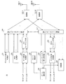
- FIG. 1 is a diagram illustrating a configuration example of a base station 10 according to the present embodiment.
- 1 includes a discovery signal generation unit 101, a PRS generation unit 102, a data signal generation unit 103, a precoding unit 104, a weight selection unit 105, a transmission beamforming unit 106, and a communication unit.
- 107, an antenna 108, a reception beam forming unit 151, a feedback signal processing unit 152, a post coding unit 153, and a data signal processing unit 154 are employed.
- a configuration unit for transmitting / receiving an OFDM (Orthogonal Frequency Division Multiplexing) signal in the base station 10 for example, an IFFT (Inverse Fast Fourier Transform) processing unit, a CP (Cyclic Prefix) addition unit, a CP removal unit) , FFT (Fast Fourier Transform) processing unit) and the like are omitted.
- OFDM Orthogonal Frequency Division Multiplexing
- the discovery signal generation unit 101 generates the same number of discovery signals as the number M of candidate BF weights (M is an integer of 2 or more).
- the discovery signal is a reference signal used to determine a beam (BF weight).
- Discovery signal generation section 101 outputs the generated discovery signal to transmission beamforming section 106.
- the PRS generation unit 102 generates the same number of PRSs as the number M of BF weight candidates.
- PRS is a reference signal used for positioning.
- the PRS generation unit 102 outputs the generated PRS to the transmission beamforming unit 106.
- the data signal generation unit 103 performs encoding processing and modulation processing on data of K streams (K is an integer equal to or less than M) for the terminal 20, and generates a data signal (downlink signal).
- the data signal generation unit 103 outputs the generated data signal to the precoding unit 104.
- FIG. 1 only the data signal generation unit 103 for one terminal 20 (i-th terminal 20) is shown, but the base station 10 has a data signal generation unit 103 for each of the plurality of terminals 20. Shall.
- the precoding unit 104 multiplies the K data signals output from the data signal generation unit 103 by a precoding matrix for each subcarrier to generate M data signals after precoding. Precoding section 104 outputs the generated M data signals to transmission beamforming section 106.
- the weight selection unit 105 selects a BF weight that forms the transmission beam selected by the terminal 20 based on the transmission beam information output from the feedback signal processing unit 152, and transmits the transmission beam forming unit 106 and the reception beam forming unit. 151 is output.
- the transmission beamforming unit 106 multiplies the discovery signal output from the discovery signal generation unit 101 by a BF weight candidate before starting data transmission. Transmit beamforming section 106 outputs a discovery signal after multiplication by BF weight candidates to communication section 107.
- the transmission beamforming unit 106 multiplies the PRS output from the PRS generation unit 102 by a BF weight candidate after the discovery signal is transmitted and before the data transmission is started. Transmit beamforming section 106 outputs to PRS 107 the PRS after multiplying by the BF weight candidate.
- the transmission beamforming unit 106 multiplies the data signal output from the precoding unit 104 by the BF weight output from the weight selection unit 105 during data transmission. Transmit beamforming section 106 outputs the data signal after being multiplied by the BF weight to communication section 107.
- Communication units 107-1 to 107-M are provided corresponding to M antennas 108 (antenna elements), respectively.
- Each communication unit 107 performs transmission processing such as D / A conversion and up-conversion on the signal output from the transmission beamforming unit 106 to generate a radio frequency transmission signal.
- Each communication unit 107 transmits the generated radio frequency transmission signal from each of the M antennas 108 to the terminal 20.
- M beam candidates are formed by transmitting a signal obtained by multiplying each of the BF weight candidates from the M antennas 108 (see FIG. 4).
- each communication unit 107 performs reception processing such as down-conversion and A / D conversion on the signal transmitted from the terminal 20 and received by each of the M antennas 108.
- Each communication unit 107 outputs a data signal and a feedback signal obtained by performing reception processing to the reception beamforming unit 151.
- the reception beamforming unit 151 multiplies the feedback signal output from each communication unit 107 by a BF weight candidate before starting data reception.
- Reception beamforming section 151 outputs a feedback signal after multiplication by BF weight candidates to feedback signal processing section 152.
- reception beamforming unit 151 multiplies the data signal output from each communication unit 107 by the BF weight output from the weight selection unit 105 at the time of data reception.
- Reception beamforming section 151 outputs the data signal after being multiplied by the BF weight to postcoding section 153.
- the feedback signal processing unit 152 performs demodulation processing and decoding processing on the feedback signal output from the reception beam forming unit 151, and extracts transmission beam information indicating the index of the transmission beam selected by the terminal 20.
- the feedback signal processing unit 152 outputs the extracted transmission beam information to the weight selection unit 105.
- the post-coding unit 153 performs post-coding on the data signal output from the reception beamforming unit 151 using the post-coding matrix.
- the post coding unit 153 outputs the post-coded data signal to the data signal processing unit 154.
- the data signal processing unit 154 performs demodulation processing and decoding processing on the data signal output from the post-coding unit 153, and obtains K streams of data from the i-th terminal 20.
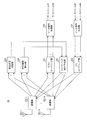
- FIG. 2 is a block diagram illustrating a configuration example of the terminal 20 according to the first embodiment.
- the terminal 20 shown in FIG. 2 includes an antenna 201, a communication unit 202, a reception quality measurement unit 203, a positioning accuracy calculation unit 204, a beam selection unit 205, a positioning unit 206, a post coding unit 207, and a data signal.
- a configuration including a processing unit 208, a feedback signal generation unit 251, a data signal generation unit 252, and a precoding unit 253 is employed.
- FIG. 2 shows the configuration of the i-th terminal 20 as an example.
- description of components for example, IFFT processing unit, CP adding unit, CP removing unit, FFT processing unit for transmitting / receiving the OFDM signal in the terminal 20 is omitted.
- Communication units 202-1 to 202-N are provided corresponding to N antennas 201 (N is an integer of 2 or more), respectively.
- Each communication unit 202 performs reception processing such as down-conversion and A / D conversion on the reception signal received via the antenna 201.
- Each communication unit 202 outputs the discovery signal obtained by performing the reception process to the reception quality measurement unit 203 and the positioning accuracy calculation unit 204, and outputs the PRS obtained by performing the reception process to the positioning unit 206, The signal is output to the post coding unit 207.
- each communication unit 202 performs transmission processing such as D / A conversion and up-conversion on the feedback signal output from the feedback signal generation unit 251 or the data signal output from the precoding unit 253 to perform radio frequency transmission.
- the transmission signal is generated.
- Each communication unit 202 transmits the generated radio frequency transmission signal from each of the N antennas 201 to the base station 10.
- the reception quality measurement unit 203 uses the discovery signal output from the communication unit 202 to measure RSRP between the base station 10 and the terminal 20 of each beam candidate. Reception quality measurement section 203 outputs the measured RSRP of each beam candidate to beam selection section 205.
- the positioning accuracy calculation unit 204 uses the discovery signal output from the communication unit 202 to calculate a parameter related to the positioning accuracy of each beam candidate (hereinafter simply referred to as “positioning accuracy”).
- the positioning accuracy calculation unit 204 outputs the calculated positioning accuracy of each beam candidate to the beam selection unit 205. A specific method for calculating the positioning accuracy in the positioning accuracy calculation unit 204 will be described later.
- the beam selection unit 205 selects a transmission beam in the base station 10 from the M beams based on the RSRP from the reception quality measurement unit 203. Specifically, the beam selection unit 205 selects a beam having the highest RSRP as a transmission beam. The beam selection unit 205 outputs transmission beam information indicating the index of the selected transmission beam to the feedback signal generation unit 251.
- the beam selection unit 205 selects a positioning beam at the base station 10 from the M beams based on the positioning accuracy from the positioning accuracy calculation unit 204. Specifically, the beam selection unit 205 selects a beam having the best positioning accuracy as a positioning beam. The beam selection unit 205 outputs positioning beam information indicating the index of the selected positioning beam to the positioning unit 206.
- the positioning unit 206 performs positioning (position estimation) of the own device (terminal 20) using the PRS transmitted in the positioning beam of the positioning beam information output from the beam selection unit 205. Specifically, the positioning unit 206 estimates the direction of the terminal 20 with respect to the base station 10 based on the AOD corresponding to the positioning beam. Further, the positioning unit 206 estimates the distance from the base station 10 to the terminal 20 based on the PRS TOA, TDOA, RSSI, and the like.
- the post-coding unit 207 performs post-coding on the data signal output from the communication unit 202 using the post-coding matrix, and outputs the post-coded data signal to the data signal processing unit 208.
- the data signal processing unit 208 performs demodulation processing and decoding processing on the data signal output from the post-coding unit 207 to obtain K streams of data for the i-th terminal 20.
- the feedback signal generation unit 251 performs encoding processing and modulation processing on the transmission beam information output from the beam selection unit 205 to generate a feedback signal.
- the feedback signal generation unit 251 outputs the generated feedback signal to the communication unit 202.
- the feedback signal may include position information acquired by the terminal 20 by other means such as a satellite signal.
- the data signal generation unit 252 performs encoding processing and modulation processing on data of K streams (K is an integer equal to or less than M) for the base station 10 to generate a data signal (uplink signal).
- the data signal generation unit 252 outputs the generated data signal to the precoding unit 253.
- the precoding unit 253 multiplies the K data signals output from the data signal generation unit 252 by a precoding matrix for each subcarrier to generate M data signals after precoding.
- the precoding unit 253 outputs the generated M data signals to the communication unit 202.
- the base station 10 switches beam candidates #i (i is an index value and any integer from 1 to M) at a constant transmission interval ⁇ ref from # 1 to #M. To do. Further, it is assumed that the transmission interval ⁇ ref is known in the terminal 20.
- Positioning accuracy computing section 204 first uses a discovery signal output from the communication unit 202, measures the reception time t i of each beam candidate #i.
- the arrival time difference T of the beam candidate #i with reference to the beam candidate # 1 by the following equation (1) from the reception time t 1 of the beam candidate # 1 , the reception time t i of the beam candidate #i, and the transmission interval ⁇ ref. i is calculated.
- the arrival time is the time from the signal transmission time of the base station 10 to the signal reception time of the terminal 20.
- T i (t i ⁇ t 1 ) ⁇ (i ⁇ 1) ⁇ ⁇ ref (1)
- the arrival time difference T i of the beam candidate #i is set as the positioning accuracy. That is, as the arrival time difference T i is short, the positioning accuracy is improved.
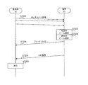
- FIG. 3 is a sequence diagram showing operations of base station 10 and terminal 20 according to the present embodiment.
- FIG. 4 is a figure which shows an example of the propagation path condition between the base station 10 and the terminal 20 which concerns on this Embodiment.
- the base station 10 transmits a discovery signal to the terminal 20 (ST101).
- Each discovery signal is multiplied by a BF weight candidate.
- the discovery signal transmitted for each beam candidate (BF weight candidate) is not precoded and transmitted to all antennas 201 of all terminals 20.
- terminal 20 uses the discovery signal to measure RSRP and positioning accuracy corresponding to each beam candidate, and selects a transmission beam and a positioning beam (ST102, ST103).
- the terminal 20 since the RSRP of the discovery signal transmitted in the beam # 2 is the highest, the terminal 20 selects the beam # 2 as a transmission beam. Further, since the positioning signal transmitted with the beam #m has the best positioning accuracy, the terminal 20 selects the beam #m as the positioning beam. As a result, the beam #m directed in the direction in which the terminal 20 exists is used for positioning.
- the base station 10 transmits a PRS to the terminal 20 (ST104).
- Each PRS is multiplied by a BF weight candidate.
- the PRS transmitted for each BF weight candidate is not precoded and transmitted to all antennas 201 of all terminals 20.
- terminal 20 performs positioning (position estimation of terminal 20) using the PRS transmitted in the positioning beam (#m) (ST105).
- the transmission beam and the positioning beam are selected using the discovery signal transmitted by each beam candidate.
- PRS is also transmitted by each beam candidate. Therefore, the transmission beam may be selected using the discovery signal, and the positioning beam may be selected using the PRS.
- the beam having the highest reception quality is selected as the transmission beam, and the beam having the best positioning accuracy is selected as the positioning beam.
- the terminal 20 performs positioning processing using a signal transmitted from the base station 10 in a beam directed in the direction in which the terminal 20 exists. Therefore, positioning using Massive MIMO technology can be performed with high accuracy.
- the beam selection unit 205 selects a positioning beam based only on the calculation result of the positioning accuracy calculation unit 204 has been described.
- the present embodiment is not limited to this, and the positioning accuracy calculation is performed.
- the positioning beam may be selected by referring to the positioning beam selected in the past together with the calculation result of the unit 204.
- the beam selection unit 205 sets an allowable value of the beam index difference, and the difference between the index of the positioning beam selected last time and the index of the beam candidate with the highest positioning accuracy is greater than the allowable value.
- the previously selected beam may be selected again as a positioning beam.
- the allowable value is “4”
- the index of the positioning beam selected last time is “# 1”
- the index of the beam candidate having the highest positioning accuracy this time is “# 5”
- the beam selection unit 205 selects beam # 1 without selecting beam # 5 as a positioning beam.
- a positioning beam can be selected with high accuracy without being affected by a temporary change in the propagation path state between the base station 10 and the terminal 20.
- the user can arbitrarily determine the allowable value.
- the allowable value may be set to a smaller value as the beam width is wider. Thereby, it is possible to cope with a change in the beam index due to the movement of the terminal 20. Further, the allowable value may be set to a smaller value as the arrival time is shorter.
- the beam selection unit 205 may refer to the probability distribution of the beam index within a certain period and select the beam having the highest selection probability as the positioning beam.
- a positioning beam may be selected by combining the above methods. Furthermore, a measurement result of received power (reception quality) may be combined with the above method.
- FIG. 5 is a diagram illustrating a configuration example of the base station 10 according to Variation 1 of the present embodiment.
- the base station 10 shown in FIG. 5 employs a configuration in which a positioning unit 155 is added to the base station 10 shown in FIG.
- the feedback signal processing unit 152 performs demodulation processing and decoding processing on the feedback signal output from the reception beam forming unit 151, transmission beam information indicating the index of the transmission beam selected in the terminal 20, and the terminal 20 Positioning beam information indicating the index of the positioning beam selected in is extracted.
- the feedback signal processing unit 152 outputs the extracted transmission beam information to the weight selection unit 105, and outputs the extracted positioning beam information to the positioning unit 155.
- the positioning unit 155 estimates the direction of the terminal 20 based on the AOD corresponding to the positioning beam of the positioning beam information output from the feedback signal processing unit 152.
- each of the plurality of base stations 10 estimates the direction of the terminal 20 from the AOD corresponding to the positioning beam. Thereby, the positioning of the terminal 20 can be performed with high accuracy.
- FIG. 6 is a block diagram illustrating a configuration example of the terminal 20 according to Variation 1 of the present embodiment.
- the same components as those in FIG. 2 are denoted by the same reference numerals as those in FIG.
- the terminal 20 shown in FIG. 6 employs a configuration in which the positioning unit 206 is deleted from the terminal 20 shown in FIG.
- the beam selection unit 205 outputs the transmission beam information and the positioning beam information to the feedback signal generation unit 251.
- the feedback signal generation unit 251 performs encoding processing and modulation processing on the transmission beam information and positioning beam information output from the beam selection unit 205, and generates a feedback signal.
- the feedback signal generation unit 251 outputs the generated feedback signal to the communication unit 202.
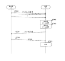
- FIG. 7 is a sequence diagram showing operations of base station 10 and terminal 20 according to variation 1 of the present embodiment.
- the steps common to those in FIG. 3 are denoted by the same reference numerals as those in FIG.
- the terminal 20 After selecting the transmission beam and the positioning beam (ST102, ST103), the terminal 20 transmits a feedback signal including the transmission beam information and the positioning beam information to the base station 10 (ST111).
- the base station 10 performs positioning (position estimation) of the terminal 20 using the signal transmitted by the positioning beam (#m) (ST112).
- the beam having the highest reception quality is selected as the transmission beam, and the beam having the best positioning accuracy is selected as the positioning beam.
- the base station 10 performs a positioning process using a signal received by a beam directed in the direction in which the terminal 20 exists. Therefore, positioning using Massive MIMO technology can be performed with high accuracy.
- a configuration example of the base station 10 according to Variation 2 of the present embodiment is the same as FIG. However, in variation 2, the functions of the PRS generation unit 102 and the feedback signal processing unit 152 are changed, and the functions of the weight selection unit 105 and the transmission beamforming unit 106 are added as described below.
- the PRS generation unit 102 generates one PRS and outputs it to the transmission beamforming unit 106.
- the weight selection unit 105 is a BF weight that forms the positioning beam selected by the terminal 20 based on the positioning beam information output from the feedback signal processing unit 152 after the discovery signal is transmitted and before the data transmission is started. Is output to the transmission beamforming unit 106.
- the transmission beamforming unit 106 multiplies the PRS output from the PRS generation unit 102 by the BF weight corresponding to the positioning beam after transmitting the discovery signal and before starting data transmission, and Output.
- the feedback signal processing unit 152 performs demodulation processing and decoding processing on the feedback signal output from the reception beam forming unit 151, and extracts transmission beam information and positioning beam information.
- the feedback signal processing unit 152 outputs the extracted transmission beam information and positioning beam information to the weight selection unit 105.
- ⁇ Terminal configuration> The configuration of terminal 20 according to variation 2 of the present embodiment is the same as FIG. However, in the variation 2, the functions of the beam selection unit 205 and the feedback signal generation unit 251 are changed as follows.
- the beam selection unit 205 outputs the positioning beam information to the positioning unit 206 and outputs the transmission beam information and the positioning beam information to the feedback signal generation unit 251.
- the feedback signal generation unit 251 performs encoding processing and modulation processing on the transmission beam information and positioning beam information output from the beam selection unit 205, and generates a feedback signal.
- the feedback signal generation unit 251 outputs the generated feedback signal to the communication unit 202.
- FIG. 8 is a sequence diagram showing operations of base station 10 and terminal 20 according to variation 2 of the present embodiment.
- steps common to those in FIG. 3 are denoted by the same reference numerals as those in FIG.
- the terminal 20 After selecting the transmission beam and the positioning beam (ST102, ST103), the terminal 20 transmits a feedback signal including the transmission beam information and the positioning beam information to the base station 10 (ST121).
- the base station 10 transmits a PRS using the positioning beam (#m) (ST122).
- terminal 20 performs positioning (position estimation of terminal 20) using the PRS transmitted in the positioning beam (#m) (ST123). Specifically, the positioning unit 206 estimates the direction of the terminal 20 with respect to the base station 10 based on the AOD corresponding to the positioning beam. Further, the positioning unit 206 estimates the distance from the base station 10 to the terminal 20 based on the PRS TOA, TDOA, RSSI, and the like.
- a plurality of base stations 10 may estimate the position of the terminal 20 based on AOD, TOA, TDOA, RSSI, and the like.
- the beam having the highest reception quality is selected as the transmission beam, and the beam having the best positioning accuracy is selected as the positioning beam.
- the terminal 20 can perform the positioning process using the signal transmitted in the beam directed in the direction in which the terminal 20 exists. Therefore, positioning using MassiveMaMIMO technology can be performed with high accuracy.
- the base station 10 since the terminal 20 feeds back the positioning beam information to the base station 10, the base station 10 only needs to transmit one PRS using the positioning beam, and overhead. Can be reduced.
- a configuration example of the base station 10 according to Variation 3 of the present embodiment is the same as FIG. However, in variation 3, the functions of the PRS generation unit 102 and the feedback signal processing unit 152 are changed as described below, and the functions of the weight selection unit 105 and the transmission beamforming unit 106 are added.
- the PRS generation unit 102 generates one PRS and outputs it to the transmission beamforming unit 106.
- the weight selection unit 105 is a BF weight that forms the positioning beam selected by the terminal 20 based on the positioning beam information output from the feedback signal processing unit 152 after the discovery signal is transmitted and before the data transmission is started. Is output to the transmission beamforming unit 106.
- the transmission beamforming unit 106 multiplies the PRS output from the PRS generation unit 102 by the BF weight corresponding to the positioning beam after transmitting the discovery signal and before starting data transmission, and Output.
- the feedback signal processing unit 152 performs demodulation processing and decoding processing on the feedback signal output from the reception beam forming unit 151, and extracts transmission beam information and positioning beam information.
- the feedback signal processing unit 152 outputs the extracted transmission beam information and positioning beam information to the weight selection unit 105.
- Terminal 20 The configuration of terminal 20 according to variation 2 of the present embodiment is the same as FIG. However, in the variation 2, the functions of the positioning accuracy calculation unit 204 and the feedback signal generation unit 251 are added as follows.
- the positioning accuracy calculation unit 204 calculates the positioning accuracy of the positioning beam using the PRS output from the communication unit 202.
- the positioning accuracy calculation unit 204 outputs the calculated positioning accuracy of the positioning beam to the feedback signal generation unit 251.
- the feedback signal generation unit 251 performs encoding processing and modulation processing on the positioning accuracy output from the positioning accuracy calculation unit 204, and generates a feedback signal.
- the feedback signal generation unit 251 outputs the generated feedback signal to the communication unit 202.
- FIG. 9 is a sequence diagram showing operations of base station 10 and terminal 20 according to variation 3 of the present embodiment.
- the same steps as those in FIG. 7 are denoted by the same reference numerals as those in FIG.
- the base station 10 After receiving the feedback signal from the terminal 20 (ST111), the base station 10 transmits a PRS using the positioning beam (#m) (ST131).
- the terminal 20 calculates positioning information (positioning accuracy, TOA, TDOA, RSSI, etc.) using the PRS transmitted in the positioning beam (#m) (ST132), and a feedback signal including the positioning information. Is transmitted to the base station 10 (ST133).
- the base station 10 performs positioning (position estimation) of the terminal 20 based on the terminal direction corresponding to the positioning beam (#m) selected by the terminal and the positioning information acquired using the positioning beam. (ST134).
- the beam having the highest reception quality is selected as the transmission beam, and the beam having the best positioning accuracy is selected as the positioning beam.
- the base station 10 performs a positioning process using a signal received by a beam directed in the direction in which the terminal 20 exists. Therefore, positioning using Massive MIMO technology can be performed with high accuracy.
- the base station 10 since the terminal 20 feeds back the positioning beam information to the base station 10, the base station 10 only needs to transmit one PRS using the positioning beam, and overhead. Can be reduced. Furthermore, since position estimation can be performed in consideration of not only AOD but also TOA or TDOA, positioning with higher accuracy is possible.
- PRS is used as a positioning reference signal.
- the present invention is not limited to this, and a signal other than PRS may be used as a positioning reference signal.
- the present invention is not limited to this, and other parameters such as RSRQ, RSSI, path loss, and SINR may be used.
- the terminal direction may be estimated using a plurality of these parameters.
- the first embodiment has been described above.
- FIG. 10 is a sequence diagram showing operations of base station 10 and terminal 20 according to the present embodiment.
- FIG. 11 is a figure which shows an example of the propagation path condition between the base station 10 and the terminal 20 which concerns on this Embodiment.
- the base station 10 transmits a discovery signal to the terminal 20 (ST201).
- Each discovery signal is multiplied by a BF weight candidate.
- the discovery signal transmitted for each beam candidate (BF weight candidate) is not precoded and transmitted to all antennas 201 of all terminals 20.
- terminal 20 uses the discovery signal to measure RSRP and positioning accuracy corresponding to each beam candidate, and selects a transmission beam and a positioning beam (ST202, ST203).
- terminal 20 transmits a feedback signal including transmission beam information and positioning beam information to base station 10 (ST204).
- terminal 20 transmits a UL signal to base station 10 (ST205).
- the base station 10 performs positioning (position estimation of the terminal 20) based on the terminal direction corresponding to the positioning beam (#m) and the positioning information acquired using the UL signal (ST206).
- the beam having the highest reception quality is selected as the transmission beam, and the beam having the best positioning accuracy is selected as the positioning beam.
- the base station 10 performs a positioning process using a signal received by a beam directed in the direction in which the terminal 20 exists. Therefore, positioning using Massive MIMO technology can be performed with high accuracy.
- FIG. 12 is a diagram illustrating a configuration example of the base station 10 according to variation 1 of the second embodiment.
- components common to those in FIG. 5 are assigned the same reference numerals as those in FIG.
- the base station 10 shown in FIG. 12 employs a configuration in which a beam selection unit 156 is added to the base station 10 shown in FIG.
- the feedback signal processing unit 152 performs demodulation processing and decoding processing on the feedback signal output from the reception beam forming unit 151, and extracts the RSRP and positioning accuracy of each beam candidate measured at the terminal 20.
- the feedback signal processing unit 152 outputs the extracted RSRP and positioning accuracy of each beam candidate to the beam selection unit 156.
- the beam selection unit 156 selects a transmission beam based on the RSRP of each beam candidate. Specifically, the beam selection unit 156 selects a beam having the highest RSRP as a transmission beam. The beam selection unit 156 outputs transmission beam information indicating the index of the selected transmission beam to the weight selection unit 105.
- the beam selection unit 156 selects a positioning beam based on the positioning accuracy of each beam candidate. Specifically, the beam selection unit 156 selects a beam having the best positioning accuracy as a positioning beam. The beam selection unit 156 outputs positioning beam information indicating the index of the selected positioning beam to the weight selection unit 105 and the positioning unit 155.
- the weight selection unit 105 selects a BF weight that forms a transmission beam based on the transmission beam information output from the beam selection unit 156, and outputs the BF weight to the transmission beamforming unit 106 and the reception beamforming unit 151.
- the weight selection unit 105 selects a BF weight that forms a positioning beam based on the positioning beam information output from the beam selection unit 156 and outputs the BF weight to the reception beam forming unit 151.
- the positioning unit 155 performs positioning (position estimation) of the terminal 20 using the signal received in the positioning beam selected by the beam selection unit 156.
- FIG. 13 is a block diagram illustrating a configuration example of the terminal 20 according to the second embodiment.
- the terminal 20 shown in FIG. 13 employs a configuration in which the beam selection unit 205 is deleted from the terminal 20 shown in FIG.
- the reception quality measurement unit 203 uses the discovery signal output from the communication unit 202 to measure RSRP between the base station 10 and the terminal 20 of each beam candidate. Reception quality measurement section 203 outputs the measured RSRP of each beam candidate to feedback signal generation section 251.
- the positioning accuracy calculation unit 204 uses the discovery signal output from the communication unit 202 to calculate the positioning accuracy of each beam candidate.
- the positioning accuracy calculation unit 204 outputs the calculated positioning accuracy of each beam candidate to the feedback signal generation unit 251.
- the feedback signal generation unit 251 performs encoding processing and modulation processing on the RSRP and positioning accuracy of each beam candidate output from the reception quality measurement unit 203 to generate a feedback signal.
- the feedback signal generation unit 251 outputs the generated feedback signal to the communication unit 202.
- FIG. 14 is a sequence diagram showing operations of base station 10 and terminal 20 according to variation 1 of the present embodiment.
- terminal 20 transmits a UL (uplink) signal to base station 10 (ST211). At this time, the terminal 20 transmits the same number of UL signals as the number of beam candidates. Note that the terminal 20 may add reference information to the UL signal when the base station 10 performs beam selection.
- the reference information is, for example, position information acquired by the terminal 20 using other means such as GPS or BLE (Bluetooth (registered trademark) Low Energy).
- the base station 10 selects a transmission beam based on the RSRP of the UL signal of each candidate beam (ST212), and selects a positioning beam based on the positioning accuracy of the UL signal of each candidate beam (ST212). ST213).
- terminal 20 transmits a UL signal to base station 10 (ST214).
- the base station 10 performs positioning (position estimation of the terminal 20) based on the terminal direction corresponding to the positioning beam (#m) and the positioning information acquired using the UL signal (ST215).
- the position of the terminal 20 can be estimated based on the positioning information acquired by the plurality of base stations 10.
- the beam having the highest reception quality is selected as the transmission beam, and the beam having the best positioning accuracy is selected as the positioning beam.
- the terminal 20 can perform the positioning process using the signal transmitted in the beam directed in the direction in which the terminal 20 exists. Therefore, positioning using MassiveMaMIMO technology can be performed with high accuracy.
- PRS is used as a positioning reference signal.
- the present invention is not limited to this, and a signal other than PRS may be used as a positioning reference signal.
- the present invention is not limited to this, and other parameters such as RSRQ, RSSI, path loss, and SINR may be used.
- the terminal direction may be estimated using a plurality of these parameters.
- the embodiment 2 has been described above.
- Embodiment 3 In Embodiment 3, a case where the base station 10 and the terminal 20 perform BF will be described.
- the configuration of base station 10 of Embodiment 3 is the same as that shown in FIG.
- FIG. 15 is a block diagram illustrating a configuration example of the terminal 20 according to the third embodiment.
- the same components as those in FIG. 2 are denoted by the same reference numerals as those in FIG.
- the terminal 20 shown in FIG. 15 adopts a configuration in which a weight selection unit 209, a reception beamforming unit 210, and a transmission beamforming unit 254 are added to the terminal 20 shown in FIG.
- the weight selection unit 209 selects a BF weight forming a transmission beam based on the transmission beam information output from the beam selection unit 205, and outputs the BF weight to the reception beam forming unit 210 and the transmission beam forming unit 254.
- the weight selection unit 209 selects a BF weight forming a positioning beam based on the positioning beam information output from the beam selection unit 205, and outputs the BF weight to the reception beam forming unit 210 and the transmission beam forming unit 254.
- the reception beamforming unit 210 multiplies the downlink signal output from each communication unit 202 by the BF weight that forms the transmission beam output from the weight selection unit 209 during data reception, and receives the reception quality measurement unit. 203, the positioning accuracy calculation unit 204, and the post coding unit 207.
- reception beamforming unit 210 multiplies the downlink signal output from each communication unit 202 by a BF weight that forms a positioning beam output from the weight selection unit 209 during positioning, and performs positioning unit 206. Output to.
- the transmission beamforming unit 254 transmits the transmission beam output from the weight selection unit 209 in response to the data signal output from the precoding unit 253 or the feedback signal output from the feedback signal generation unit during data transmission. Is multiplied by the BF weight forming the signal, and output to the communication unit 202.
- the transmission beamforming unit 254 multiplies the data signal output from the precoding unit 253 by the BF weight forming the positioning beam output from the weight selection unit 209 during positioning, and the communication unit 202 Output to.
- FIG. 16 is a sequence diagram showing operations of base station 10 and terminal 20 according to the present embodiment.
- FIG. 17 is a diagram illustrating an example of a propagation path condition between the base station 10 and the terminal 20 according to the present embodiment.
- the base station 10 transmits a discovery signal to the terminal 20 (ST301).
- Each discovery signal is multiplied by a BF weight candidate.
- the discovery signal transmitted for each beam candidate (BF weight candidate) is not precoded and transmitted to all antennas 201 of all terminals 20.
- terminal 20 uses the discovery signal to measure RSRP and positioning accuracy corresponding to each beam candidate, and selects a transmission beam and a positioning beam (ST302, ST303).
- the terminal 20 since the RSRP of the discovery signal transmitted from the base station 10 in the beam # 2 and received in the beam # 2 of the terminal 20 is the highest, the terminal 20 has the beam # 2 of the base station 10 and the terminal 20 Beam # 2 is selected as a transmission beam.
- the terminal 20 since the positioning accuracy of the discovery signal transmitted from the base station 10 in the beam #m and received in the beam #n of the terminal 20 is the best, the terminal 20 uses the beam #m of the base station 10 and the beam # of the terminal 20. Select n as a positioning beam. Accordingly, the beam #m of the base station 10 directed in the direction in which the terminal 20 exists and the beam #n of the terminal 20 directed in the direction in which the base station 10 exists are used for positioning. become.
- the base station 10 transmits a PRS to the terminal 20 (ST304).
- Each PRS is multiplied by a BF weight candidate.
- the PRS transmitted for each BF weight candidate is not precoded and transmitted to all antennas 201 of all terminals 20.
- the terminal 20 performs positioning (position estimation of the terminal 20) using the PRS transmitted in the positioning beam (#m) of the base station 10 and received in the positioning beam (#n) of the terminal 20. Perform (ST305).
- the base station 10 and the terminal 20 may be interchanged to perform the operation.
- the beam of the base station 10 and the beam of the terminal 20 with the highest reception quality are selected as the transmission beams, and the beam of the base station 10 and the terminal 20 of the positioning accuracy with the highest positioning accuracy are selected.
- Each of the beams is selected as a positioning beam.
- the terminal 20 performs positioning processing using a signal transmitted from the base station 10 in a beam directed in the direction in which the terminal 20 exists. Therefore, positioning using Massive MIMO technology can be performed with high accuracy.
- the base station 10 transmits the PRS using the positioning beam selected by the terminal 20, and the terminal 20 can perform positioning.
- the terminal 20 can perform positioning.
- operations of base station 10 and terminal 20 in this case will be described.
- FIG. 18 is a sequence diagram showing operations of base station 10 and terminal 20 according to variation 1 of the present embodiment.
- steps common to FIG. 16 are denoted by the same reference numerals as those in FIG.
- the terminal 20 After selecting the transmission beam and the positioning beam (ST302, ST303), the terminal 20 transmits a feedback signal including the transmission beam information and the positioning beam information to the base station 10 (ST321).
- the base station 10 transmits a PRS using the positioning beam (#m) (ST322).
- the terminal 20 performs positioning (position estimation of the terminal 20) using the PRS transmitted in the positioning beam (#m) of the base station 10 and received in the positioning beam (#n) of the terminal 20. Perform (ST323).
- the base station 10 can transmit the PRS using the positioning beam selected by the terminal 20, and the base station 10 can perform the positioning. .
- the base station 10 and terminal 20 in this case will be described.
- FIG. 19 is a sequence diagram showing operations of base station 10 and terminal 20 according to variation 2 of the present embodiment.
- steps common to those in FIG. 18 are denoted by the same reference numerals as those in FIG.
- the base station 10 After receiving the feedback signal from the terminal 20 (ST321), the base station 10 transmits a PRS using the positioning beam (#m) (ST331).
- terminal 20 calculates the positioning accuracy using the PRS transmitted in the positioning beam (#m) of base station 10 and received in the positioning beam (#n) of terminal 20 (ST332). Then, a feedback signal including positioning accuracy is transmitted to the base station 10 (ST333).
- base station 10 performs positioning (position estimation) of terminal 20 based on the positioning accuracy of positioning beam (#m) of base station 10 and positioning beam (#n) of terminal 20 (ST334). .
- PRS is used as a positioning reference signal.
- the present invention is not limited to this, and a signal other than PRS may be used as a positioning reference signal.
- the present invention is not limited to this, and other parameters such as RSRQ, RSSI, path loss, and SINR may be used.
- the terminal direction may be estimated using a plurality of these parameters.
- the base station 10 transmits a discovery signal using a relatively wide beam candidate in the low frequency band, and the base station 10 or the terminal 20 selects the first positioning beam. .
- a high frequency band beam having a center direction within a range of ⁇ X ° from the center direction of the first positioning beam is selected as a beam candidate. Then, the final positioning beam is selected from the selected beam candidates in the high frequency band.
- the low-frequency band beam candidate having the highest PRPS in the first stage is selected as the first positioning beam
- the high-frequency band candidate having the best measurement accuracy is selected in the second stage. It may be selected as a positioning beam.
- the low-frequency band candidate with the best positioning accuracy is selected as the first positioning beam
- the high-frequency band candidate with the highest PRPS is selected as the final positioning beam. May be.
- each functional block may be realized by one device physically and / or logically coupled, and two or more devices physically and / or logically separated may be directly and / or indirectly. (For example, wired and / or wireless) and may be realized by these plural devices.
- a wireless base station, a user terminal, etc. in an embodiment of the present invention may function as a computer that performs processing of the wireless communication method of the present invention.
- FIG. 20 is a diagram illustrating an example of a hardware configuration of a radio base station and a user terminal according to an embodiment of the present invention.
- the base station 10 and the terminal 20 described above may be physically configured as a computer device including a processor 1001, a memory 1002, a storage 1003, a communication device 1004, an input device 1005, an output device 1006, a bus 1007, and the like.
- the term “apparatus” can be read as a circuit, a device, a unit, or the like.
- the hardware configuration of the base station 10 and the terminal 20 may be configured to include one or a plurality of devices illustrated in the figure, or may be configured not to include some devices.
- processor 1001 may be implemented by one or more chips.
- Each function in the base station 10 and the terminal 20 is obtained by reading predetermined software (program) on hardware such as the processor 1001 and the memory 1002, so that the processor 1001 performs computation and communication by the communication device 1004 or memory This is realized by controlling data reading and / or writing in the storage 1003 and the storage 1003.
- the processor 1001 controls the entire computer by operating an operating system, for example.
- the processor 1001 may be configured by a central processing unit (CPU) including an interface with peripheral devices, a control device, an arithmetic device, a register, and the like.
- CPU central processing unit
- the processor 1001 reads a program (program code), software module, or data from the storage 1003 and / or the communication device 1004 to the memory 1002, and executes various processes according to these.
- a program program code
- the control unit 101 of the base station 10 may be realized by a control program stored in the memory 1002 and operated by the processor 1001, and may be realized similarly for other functional blocks.
- the above-described various processes have been described as being executed by one processor 1001, they may be executed simultaneously or sequentially by two or more processors 1001.
- the processor 1001 may be implemented by one or more chips. Note that the program may be transmitted from a network via a telecommunication line.
- the memory 1002 is a computer-readable recording medium and includes at least one of ROM (Read Only Memory), EPROM (Erasable Programmable ROM), EEPROM (Electrically Erasable Programmable ROM), RAM (Random Access Memory), and the like. May be.
- the memory 1002 may be called a register, a cache, a main memory (main storage device), or the like.
- the memory 1002 can store a program (program code), a software module, and the like that can be executed to implement the wireless communication method according to the embodiment of the present invention.
- the storage 1003 is a computer-readable recording medium such as an optical disc such as a CD-ROM (Compact Disc ROM), a hard disc drive, a flexible disc, a magneto-optical disc (eg, a compact disc, a digital versatile disc, a Blu-ray). (Registered trademark) disk, smart card, flash memory (for example, card, stick, key drive), floppy (registered trademark) disk, magnetic strip, and the like.
- the storage 1003 may be referred to as an auxiliary storage device.
- the above-described storage medium may be, for example, a database including the memory 1002 and / or the storage 1003, a server, or other suitable medium.
- the communication device 1004 is hardware (transmission / reception device) for performing communication between computers via a wired and / or wireless network, and is also referred to as a network device, a network controller, a network card, a communication module, or the like.
- a network device a network controller, a network card, a communication module, or the like.
- the communication units 107 and 202 and the antennas 108 and 201 described above may be realized by the communication device 1004.
- the input device 1005 is an input device (for example, a keyboard, a mouse, a microphone, a switch, a button, a sensor, etc.) that accepts an input from the outside.
- the output device 1006 is an output device (for example, a display, a speaker, an LED lamp, etc.) that performs output to the outside.
- the input device 1005 and the output device 1006 may have an integrated configuration (for example, a touch panel).
- each device such as the processor 1001 and the memory 1002 is connected by a bus 1007 for communicating information.
- the bus 1007 may be configured with a single bus or may be configured with different buses between apparatuses.
- the base station 10 and the terminal 20 include hardware such as a microprocessor, digital signal processor (DSP), application specific integrated circuit (ASIC), programmable logic device (PLD), and field programmable gate array (FPGA). And a part or all of each functional block may be realized by the hardware.
- the processor 1001 may be implemented by at least one of these hardware.
- information notification includes physical layer signaling (for example, DCI (Downlink Control Information), UCI (Uplink Control Information)), upper layer signaling (for example, RRC (Radio Resource Control) signaling, MAC (Medium Access Control) signaling), It may be implemented by broadcast information (MIB (Master Information Block), SIB (System Information Block))), other signals, or a combination thereof.
- RRC signaling may be referred to as an RRC message, and may be, for example, an RRC connection setup message, an RRC connection reconfiguration message, or the like.
- Each aspect / embodiment described herein includes LTE (Long Term Evolution), LTE-A (LTE-Advanced), SUPER 3G, IMT-Advanced, 4G, 5G, FRA (Future Radio Access), W-CDMA.
- LTE Long Term Evolution
- LTE-A Long Term Evolution-Advanced
- SUPER 3G IMT-Advanced
- 4G 5G
- FRA Full Radio Access
- W-CDMA Wideband
- GSM registered trademark
- CDMA2000 Code Division Multiple Access 2000
- UMB User Mobile Broadband
- IEEE 802.11 Wi-Fi
- IEEE 802.16 WiMAX
- IEEE 802.20 UWB (Ultra-WideBand
- the present invention may be applied to a Bluetooth (registered trademark), a system using another appropriate system, and / or a next generation system extended based on the system.
- the specific operation assumed to be performed by the base station (radio base station) in this specification may be performed by the upper node in some cases.
- various operations performed for communication with a terminal may be performed by the base station and / or other network nodes other than the base station (e.g., It is obvious that this can be performed by MME (Mobility Management Entity) or S-GW (Serving Gateway).
- MME Mobility Management Entity
- S-GW Serving Gateway
- Information, signals, and the like can be output from the upper layer (or lower layer) to the lower layer (or upper layer). Input / output may be performed via a plurality of network nodes.
- Input / output information and the like may be stored in a specific location (for example, a memory) or may be managed by a management table. Input / output information and the like can be overwritten, updated, or additionally written. The output information or the like may be deleted. The input information or the like may be transmitted to another device.
- the determination may be performed by a value represented by 1 bit (0 or 1), may be performed by a true / false value (Boolean: true or false), or may be performed by comparing numerical values (for example, a predetermined value) Comparison with the value).
- software, instructions, etc. may be transmitted / received via a transmission medium.
- software may use websites, servers, or other devices using wired technology such as coaxial cable, fiber optic cable, twisted pair and digital subscriber line (DSL) and / or wireless technology such as infrared, wireless and microwave.
- wired technology such as coaxial cable, fiber optic cable, twisted pair and digital subscriber line (DSL) and / or wireless technology such as infrared, wireless and microwave.
- DSL digital subscriber line
- wireless technology such as infrared, wireless and microwave.
- Information, signal Information, signals, etc. described herein may be represented using any of a variety of different technologies.
- data, commands, commands, information, signals, bits, symbols, chips, etc. that may be referred to throughout the above description are voltages, currents, electromagnetic waves, magnetic fields or magnetic particles, light fields or photons, or any of these May be represented by a combination of
- the channel and / or symbol may be a signal.
- the signal may be a message.
- the component carrier (CC) may be called a carrier frequency, a cell, or the like.
- radio resource may be indicated by an index.
- a base station can accommodate one or more (eg, three) cells (also referred to as sectors). When the base station accommodates multiple cells, the entire coverage area of the base station can be partitioned into multiple smaller areas, each smaller area being a base station subsystem (eg, indoor small base station RRH: Remote Radio Head) can also provide communication services.
- the term “cell” or “sector” refers to part or all of the coverage area of a base station and / or base station subsystem that provides communication services in this coverage. Further, the terms “base station”, “eNB”, “cell”, and “sector” may be used interchangeably herein.
- a base station may also be referred to in terms such as a fixed station, NodeB, eNodeB (eNB), access point, femtocell, small cell, and the like.
- a user terminal is a mobile station, subscriber station, mobile unit, subscriber unit, wireless unit, remote unit, mobile device, wireless device, wireless communication device, remote device, mobile subscriber station, access terminal, mobile by a person skilled in the art It may also be referred to as a terminal, wireless terminal, remote terminal, handset, user agent, mobile client, client, UE (User Equipment), or some other appropriate terminology.
- determining may encompass a wide variety of actions. “Judgment” and “determination” are, for example, judgment, calculation, calculation, processing, derivation, investigating, looking up (eg, table , Searching in a database or another data structure), considering ascertaining as “determining”, “deciding”, and the like.
- determination and “determination” include receiving (for example, receiving information), transmitting (for example, transmitting information), input (input), output (output), and access. (accessing) (e.g., accessing data in a memory) may be considered as “determined” or "determined”.
- determination and “decision” means that “resolving”, “selecting”, “choosing”, “establishing”, and “comparing” are regarded as “determining” and “deciding”. May be included. In other words, “determination” and “determination” may include considering some operation as “determination” and “determination”.
- connection means any direct or indirect connection or coupling between two or more elements and It can include the presence of one or more intermediate elements between two “connected” or “coupled” elements.
- the coupling or connection between the elements may be physical, logical, or a combination thereof.
- the two elements are radio frequency by using one or more wires, cables and / or printed electrical connections, and as some non-limiting and non-inclusive examples
- electromagnetic energy such as electromagnetic energy having a wavelength in the region, microwave region, and light (both visible and invisible) region, it can be considered to be “connected” or “coupled” to each other.
- the reference signal may be abbreviated as RS (Reference Signal), and may be referred to as a pilot depending on an applied standard.
- the correction RS may be referred to as TRS (Tracking ⁇ RS), PC-RS (Phase Compensation RS), PTRS (Phase Tracking RS), or Additional RS.
- the demodulation RS and the correction RS may be called differently corresponding to each. Further, the demodulation RS and the correction RS may be defined by the same name (for example, the demodulation RS).
- the phrase “based on” does not mean “based only on”, unless expressly specified otherwise. In other words, the phrase “based on” means both “based only on” and “based at least on.”
- the radio frame may be composed of one or a plurality of frames in the time domain.
- One or more frames in the time domain may be referred to as subframes, time units, etc.
- a subframe may further be composed of one or more slots in the time domain.
- the slot may be further configured with one or a plurality of symbols (OFDM (Orthogonal-Frequency-Division-Multiplexing) symbol, SC-FDMA (Single-Carrier-Frequency-Division-Multiple-Access) symbol, etc.) in the time domain.
- OFDM Orthogonal-Frequency-Division-Multiplexing
- SC-FDMA Single-Carrier-Frequency-Division-Multiple-Access
- the radio frame, subframe, slot, and symbol all represent a time unit when transmitting a signal. Radio frames, subframes, slots, and symbols may be called differently corresponding to each.
- the base station performs scheduling to allocate radio resources (frequency bandwidth, transmission power, etc. that can be used in each mobile station) to each mobile station.
- the minimum time unit of scheduling may be called TTI (Transmission Time Interval).
- one subframe may be referred to as TTI
- a plurality of consecutive subframes may be referred to as TTI
- one slot may be referred to as TTI.
- the resource unit is a resource allocation unit in the time domain and the frequency domain, and may include one or a plurality of continuous subcarriers in the frequency domain.
- one or a plurality of symbols may be included, and one slot, one subframe, or a length of 1 TTI may be included.
- One TTI and one subframe may each be composed of one or a plurality of resource units.
- the resource unit may also be called a resource block (RB: Resource Block), a physical resource block (PRB: Physical RB), a PRB pair, an RB pair, a scheduling unit, a frequency unit, or a subband.
- the resource unit may be composed of one or a plurality of REs.
- 1 RE may be any resource (for example, the smallest resource unit) smaller than a resource unit serving as a resource allocation unit, and is not limited to the name RE.
- the structure of the radio frame described above is merely an example, and the number of subframes included in the radio frame, the number of slots included in the subframe, the number of symbols and resource blocks included in the slots, and the subframes included in the resource block
- the number of carriers can be variously changed.
- notification of predetermined information is not limited to explicitly performed, but is performed implicitly (for example, notification of the predetermined information is not performed). Also good.
- One embodiment of the present invention is useful for a mobile communication system.
Abstract
基地局と端末との間に障害物が存在する場合でも、Massive MIMO技術を用いた測位を高精度に行うこと。ユーザ端末(20)において、受信品質測定部(203)は、通信部(202)から出力されたディスカバリ信号を用いて、各ビーム候補のRSRP(受信品質に関係するパラメータ)を測定する。測位精度算出部(204)は、通信部(202)から出力されたディスカバリ信号を用いて、各ビーム候補の測位精度に関係するパラメータを算出する。ビーム選択部(205)は、RSRPに基づいて伝送用ビームを選択し、測位精度に基づいて測位用ビームを選択する。
Description
本発明は、ユーザ端末および測位方法に関する。
UMTS(Universal Mobile Telecommunication System)ネットワークにおいて、更なる高速データレート、低遅延などを目的としてロングタームエボリューション(LTE:Long Term Evolution)が仕様化された。また、LTEからの更なる広帯域化および高速化を目的として、LTEの後継システムも検討されている。LTEの後継システムには、例えば、LTE-A(LTE-Advanced)、FRA(Future Radio Access)、5G(5th generation mobile communication system)、5G+(5G plus)、New-RAT(Radio Access Technology)などと呼ばれるものがある。
将来の無線通信システム(例えば、5G)では、信号伝送の更なる高速化及び干渉低減を図るために、高周波数帯(例えば、5GHz以上)において多数のアンテナ素子(例えば、100素子以上)を用いる大規模(Massive)MIMO(Multiple Input Multiple Output)技術を用いてBF(ビームフォーミング)を行うことが検討されている。
無線基地局(以下、単に「基地局」という)において、Massive MIMO技術により形成されるビームは、ユーザ端末(以下、単に「端末」という)における受信品質が最も高い方向に向けられる。
また、近年、無線技術を用いたアプリケーションとして、端末の位置情報を用いたサービスが注目されている。そのため、将来的には現在よりも高精度に測位が可能な技術が求められている。
端末等の装置の測位方法として、GNSS(Global Navigation Satellite System)の衛星(図示せず)からの測位信号を利用する方法が知られている(例えば、特許文献1参照)。なお、GNSSとは、GPS(Global Positioning System)、GLONASS、Galileo等の民間航空航法に使用可能な性能(精度・信頼性)を持つ衛星航法システムの総称である。
端末が基地局の見通し内(LOS(Line Of Site))にある場合、端末が存在する方向にビームを向けることにより、端末における受信品質(以下、「端末受信品質」という)が最も高くなるので、Massive MIMO技術により形成されるビームは、端末が存在する方向に向けられる。そのため、Massive MIMO技術のビーム制御の過程のなかにおいて端末が存在する方向を推定することができる。さらに、高周波数帯になるほど多数のアンテナ素子を用いてより細いビームを形成することができるため、上記推定精度も高まる。よって、Massive MIMO技術と端末測位との親和性は高いと考えられる。
例えば、端末が、2つの基地局のそれぞれの見通し内にある場合、各基地局の位置座標と、各基地局が選択したビームに対応したAOD(Angle Of Departure)とにより、端末の測位(位置推定)を高精度に行うことができる。また、端末からの上り信号を用いて基地局が受信に用いたビームに対応したAOA(Angle Of Arrival)を用いて位置推定を行うことができる。他にも、基地局から選択ビームを用いて送信されたPRS(Positioning Reference Signal)を用いて、TOA(Time Of Arrival)、DTOA(Difference Time Of Arrival)、RSS(Received Signal Strength)等を算出することにより、端末の測位を高精度に行うことができる。
しかしながら、基地局と端末との間に障害物が存在する場合、端末方向のビームが障害物によって減衰し、該ビームの端末受信品質が低下するので、端末方向以外のビームが選択され、測位精度が低下するおそれがある。
現在まで、Massive MIMO技術を用いた測位において、基地局と端末との間に障害物を考慮したものは開示されていない。
本発明の一態様は、基地局と端末との間に障害物が存在する場合でも、Massive MIMO技術を用いた測位を高精度に行うことができる新たな構成を提供する。
本発明の一態様に係るユーザ端末は、ビーム送信及びビーム受信を行う無線基地局と通信を行うユーザ端末であって、ビーム候補毎に、受信品質に関係する第1パラメータを測定する受信品質測定部と、前記ビーム候補毎に、前記第1パラメータと異なる、測位精度に関係する第2パラメータを算出する測位精度算出部と、を具備する。
本発明の一態様に係る測位方法は、無線基地局が、ユーザ端末に向けてビーム候補毎に信号をビーム送信し、前記ユーザ端末が、ビーム候補毎に、受信品質に関係する第1パラメータを測定し、前記第1パラメータと異なる、測位精度に関係する第2パラメータを算出し、前記ユーザ端末あるいは前記無線基地局が、前記第1パラメータに基づいてデータ伝送用ビームを選択し、前記第2パラメータに基づいて測位用ビームを選択し、前記ユーザ端末あるいは前記無線基地局が、前記測位用ビームを用いて伝送された信号を用いて測位処理を行う。
本発明の一態様によれば、基地局と端末との間に障害物が存在する場合でも、Massive MIMO技術を用いた端末の測位を高精度に行うことができる新たな構成を提供する。
以下、本発明の各実施の形態について、図面を参照して説明する。本実施の形態では、受信品質に関係するパラメータとしてRSRP(Reference Signal Received Power)を用いる。なお、他の受信品質に関係するパラメータとして、例えば、RSRQ(Reference Signal Received Quality)、RSSI(Received Signal Strength Indicator)、パスロス(伝搬損失)、SINR(Signal to Interference plus Noise Ratio)等が挙げられる。
[実施の形態1]
実施の形態1に係る無線通信システムは、少なくとも、図1に示す基地局10および図2に示す端末20を備える。端末20は、基地局10に接続している。基地局10は、端末20に対して、DL(Down Link)信号を送信する。DL信号には、例えば、DLデータ信号(例えば、PDSCH(Physical Downlink Shared Channel))と、DLデータ信号を復調および復号するためのDL制御信号(例えば、PDCCH(Physical Downlink Control Channel))とが含まれている。
実施の形態1に係る無線通信システムは、少なくとも、図1に示す基地局10および図2に示す端末20を備える。端末20は、基地局10に接続している。基地局10は、端末20に対して、DL(Down Link)信号を送信する。DL信号には、例えば、DLデータ信号(例えば、PDSCH(Physical Downlink Shared Channel))と、DLデータ信号を復調および復号するためのDL制御信号(例えば、PDCCH(Physical Downlink Control Channel))とが含まれている。
実施の形態1では、基地局10がBFを行い、端末20において、データ伝送に用いられる伝送用ビーム、及び、測位に用いられる測位用ビームを選択する場合について説明する。
<基地局の構成>
図1は、本実施の形態に係る基地局10の構成例を示す図である。図1に示す基地局10は、ディスカバリ信号生成部101と、PRS生成部102と、データ信号生成部103と、プリコーディング部104と、ウェイト選択部105と、送信ビームフォーミング部106と、通信部107と、アンテナ108と、受信ビームフォーミング部151と、フィードバック信号処理部152と、ポストコーディング部153と、データ信号処理部154と、を含む構成を採る。
図1は、本実施の形態に係る基地局10の構成例を示す図である。図1に示す基地局10は、ディスカバリ信号生成部101と、PRS生成部102と、データ信号生成部103と、プリコーディング部104と、ウェイト選択部105と、送信ビームフォーミング部106と、通信部107と、アンテナ108と、受信ビームフォーミング部151と、フィードバック信号処理部152と、ポストコーディング部153と、データ信号処理部154と、を含む構成を採る。
なお、図1では、基地局10におけるOFDM(Orthogonal Frequency Division Multiplexing)信号を送信/受信するための構成部(例えば、IFFT(Inverse Fast Fourier Transform)処理部、CP(Cyclic Prefix)付加部、CP除去部、FFT(Fast Fourier Transform)処理部)等の記載を省略している。
ディスカバリ信号生成部101は、BFウェイトの候補数M(Mは2以上の整数)と同数のディスカバリ信号を生成する。ディスカバリ信号は、ビーム(BFウェイト)を決定するために使用される参照信号である。ディスカバリ信号生成部101は、生成したディスカバリ信号を送信ビームフォーミング部106に出力する。
PRS生成部102は、BFウェイトの候補数Mと同数のPRSを生成する。PRSは、測位に使用される参照信号である。PRS生成部102は、生成したPRSを送信ビームフォーミング部106に出力する。
データ信号生成部103は、端末20向けのK個(KはM以下の整数)のストリームのデータに対して符号化処理及び変調処理を行い、データ信号(下りリンク信号)を生成する。データ信号生成部103は、生成したデータ信号をプリコーディング部104に出力する。なお、図1では、1つの端末20(第i番の端末20)に対するデータ信号生成部103のみを示しているが、基地局10は、複数の端末20にそれぞれ対するデータ信号生成部103を有するものとする。
プリコーディング部104は、データ信号生成部103から出力されたK個のデータ信号に対してプリコーディング行列をサブキャリア毎に乗算し、プリコーディング後のM個のデータ信号を生成する。プリコーディング部104は、生成したM個のデータ信号を送信ビームフォーミング部106に出力する。
ウェイト選択部105は、フィードバック信号処理部152から出力された伝送ビーム情報に基づいて、端末20において選択された伝送用ビームを形成するBFウェイトを選択し、送信ビームフォーミング部106及び受信ビームフォーミング部151に出力する。
送信ビームフォーミング部106は、データ送信開始前において、ディスカバリ信号生成部101から出力されたディスカバリ信号に対して、BFウェイトの候補をそれぞれ乗算する。送信ビームフォーミング部106は、BFウェイトの候補を乗算した後のディスカバリ信号を通信部107に出力する。
また、送信ビームフォーミング部106は、ディスカバリ信号の送信後であってデータ送信開始前において、PRS生成部102から出力されたPRSに対して、BFウェイトの候補をそれぞれ乗算する。送信ビームフォーミング部106は、BFウェイトの候補を乗算した後のPRSを通信部107に出力する。
また、送信ビームフォーミング部106は、データ送信時において、プリコーディング部104から出力されたデータ信号に対して、ウェイト選択部105から出力されたBFウェイトを乗算する。送信ビームフォーミング部106は、BFウェイトを乗算した後のデータ信号を通信部107に出力する。
通信部107-1~107-Mは、M個のアンテナ108(アンテナ素子)にそれぞれ対応して備えられる。各通信部107は、送信ビームフォーミング部106から出力された信号に対して、D/A変換、アップコンバート等の送信処理を行って無線周波数の送信信号を生成する。各通信部107は、生成した無線周波数の送信信号を、M個のアンテナ108のそれぞれから端末20に向けて送信する。なお、M個のアンテナ108から、BFウェイトの候補のそれぞれを乗算した信号を送信することにより、M個のビーム候補が形成される(図4参照)。
また、各通信部107は、端末20から送信され、M個のアンテナ108のそれぞれに受信された信号に対して、ダウンコンバート、A/D変換等の受信処理を行う。各通信部107は、受信処理を行って得られたデータ信号及びフィードバック信号を受信ビームフォーミング部151に出力する。
受信ビームフォーミング部151は、データ受信開始前において、各通信部107から出力されたフィードバック信号に対して、BFウェイトの候補をそれぞれ乗算する。受信ビームフォーミング部151は、BFウェイトの候補を乗算した後のフィードバック信号をフィードバック信号処理部152に出力する。
また、受信ビームフォーミング部151は、データ受信時において、各通信部107から出力されたデータ信号に対して、ウェイト選択部105から出力されたBFウェイトを乗算する。受信ビームフォーミング部151は、BFウェイトを乗算した後のデータ信号をポストコーディング部153に出力する。
フィードバック信号処理部152は、受信ビームフォーミング部151から出力されたフィードバック信号に対して復調処理及び復号処理を行い、端末20において選択された、伝送用ビームのインデックスを示す伝送ビーム情報を抽出する。フィードバック信号処理部152は、抽出した伝送ビーム情報をウェイト選択部105に出力する。
ポストコーディング部153は、ポストコーディング行列を用いて、受信ビームフォーミング部151から出力されたデータ信号に対してポストコーディングを行う。ポストコーディング部153は、ポストコーディング後のデータ信号をデータ信号処理部154に出力する。
データ信号処理部154は、ポストコーディング部153から出力されたデータ信号に対して復調処理及び復号処理を行い、第i番の端末20からのK個のストリームのデータを得る。
<端末の構成>
図2は、実施の形態1に係る端末20の構成例を示すブロック図である。図2に示す端末20は、アンテナ201と、通信部202と、受信品質測定部203と、測位精度算出部204と、ビーム選択部205と、測位部206と、ポストコーディング部207と、データ信号処理部208と、フィードバック信号生成部251と、データ信号生成部252と、プリコーディング部253と、を含む構成を採る。
図2は、実施の形態1に係る端末20の構成例を示すブロック図である。図2に示す端末20は、アンテナ201と、通信部202と、受信品質測定部203と、測位精度算出部204と、ビーム選択部205と、測位部206と、ポストコーディング部207と、データ信号処理部208と、フィードバック信号生成部251と、データ信号生成部252と、プリコーディング部253と、を含む構成を採る。
なお、図2は、第i番の端末20の構成を一例として示す。また、図2では、端末20におけるOFDM信号を送信/受信するための構成部(例えば、IFFT処理部、CP付加部、CP除去部、FFT処理部)等の記載を省略している。
通信部202-1~202-Nは、N個(Nは2以上の整数)のアンテナ201にそれぞれ対応して備えられる。各通信部202は、アンテナ201を介して受信した受信信号に対して、ダウンコンバート、A/D変換等の受信処理を行う。各通信部202は、受信処理を行って得られたディスカバリ信号を受信品質測定部203及び測位精度算出部204に出力し、受信処理を行って得られたPRSを測位部206に出力し、データ信号をポストコーディング部207へ出力する。
また、各通信部202は、フィードバック信号生成部251から出力されたフィードバック信号あるいはプリコーディング部253から出力されたデータ信号に対して、D/A変換、アップコンバート等の送信処理を行って無線周波数の送信信号を生成する。各通信部202は、生成した無線周波数の送信信号を、N個のアンテナ201のそれぞれから基地局10に向けて送信する。
受信品質測定部203は、通信部202から出力されたディスカバリ信号を用いて、各ビーム候補の基地局10と端末20との間のRSRPを測定する。受信品質測定部203は、測定した各ビーム候補のRSRPをビーム選択部205に出力する。
測位精度算出部204は、通信部202から出力されたディスカバリ信号を用いて、各ビーム候補の測位精度に関係するパラメータ(以下、単に「測位精度」という)を算出する。測位精度算出部204は、算出した各ビーム候補の測位精度をビーム選択部205に出力する。なお、測位精度算出部204における測位精度の具体的な算出方法については後述する。
ビーム選択部205は、M個のビームの中から、受信品質測定部203からRSRPに基づいて、基地局10における伝送用ビームを選択する。具体的には、ビーム選択部205は、RSRPが最も高いビームを伝送用ビームとして選択する。ビーム選択部205は、選択した伝送用ビームのインデックスを示す伝送ビーム情報をフィードバック信号生成部251に出力する。
また、ビーム選択部205は、M個のビームの中から、測位精度算出部204から測位精度に基づいて、基地局10における測位用ビームを選択する。具体的には、ビーム選択部205は、測位精度が最も良いビームを測位用ビームとして選択する。ビーム選択部205は、選択した測位用ビームのインデックスを示す測位ビーム情報を測位部206に出力する。
測位部206は、ビーム選択部205から出力された測位ビーム情報の測位用ビームにおいて送信されたPRSを用いて、自機(端末20)の測位(位置推定)を行う。具体的には、測位部206は、測位用ビームに対応したAODにより、基地局10に対する端末20の方向の推定を行う。さらに、測位部206は、PRSのTOA、TDOA、RSSI等に基づいて基地局10から端末20までの距離の推定を行う。
ポストコーディング部207は、ポストコーディング行列を用いて、通信部202から出力されたデータ信号に対してポストコーディングを行い、ポストコーディング後のデータ信号をデータ信号処理部208に出力する。
データ信号処理部208は、ポストコーディング部207から出力されたデータ信号に対して復調処理及び復号処理を行い、第i番の端末20に対するK個のストリームのデータを得る。
フィードバック信号生成部251は、ビーム選択部205から出力された伝送ビーム情報に対して符号化処理及び変調処理を行い、フィードバック信号を生成する。フィードバック信号生成部251は、生成したフィードバック信号を通信部202に出力する。なお、フィードバック信号には、端末20が、衛星信号等の他の手段により取得した位置情報が含まれていても良い。
データ信号生成部252は、基地局10向けのK個(KはM以下の整数)のストリームのデータに対して符号化処理及び変調処理を行い、データ信号(上りリンク信号)を生成する。データ信号生成部252は、生成したデータ信号をプリコーディング部253に出力する。
プリコーディング部253は、データ信号生成部252から出力されたK個のデータ信号に対してプリコーディング行列をサブキャリア毎に乗算し、プリコーディング後のM個のデータ信号を生成する。プリコーディング部253は、生成したM個のデータ信号を通信部202に出力する。
<測位精度の算出方法>
次に、測位精度の具体的な算出方法について、詳細に説明する。なお、前提として、基地局10は、#1から#Mまで、一定の送信間隔Δrefにおいてビーム候補#i(iは、インデックス値であり、1からMまでのいずれかの整数)を切り替えるものとする。また、端末20において、送信間隔Δrefが既知であるものとする。
次に、測位精度の具体的な算出方法について、詳細に説明する。なお、前提として、基地局10は、#1から#Mまで、一定の送信間隔Δrefにおいてビーム候補#i(iは、インデックス値であり、1からMまでのいずれかの整数)を切り替えるものとする。また、端末20において、送信間隔Δrefが既知であるものとする。
測位精度算出部204は、まず、通信部202から出力されたディスカバリ信号を用いて、各ビーム候補#iの受信時刻tiを測定する。
そして、ビーム候補#1の受信時刻t1、ビーム候補#iの受信時刻ti及び送信間隔Δrefから以下の式(1)により、ビーム候補#1を基準としたビーム候補#iの到来時間差Tiを算出する。なお、到来時間とは、基地局10の信号送信時刻から端末20の信号受信時刻までの時間である。
Ti=(ti-t1)-(i-1)×Δref ・・・(1)
Ti=(ti-t1)-(i-1)×Δref ・・・(1)
そして、ビーム候補#iの到来時間差Tiを、測位精度とする。すなわち、到来時間差Tiが短いほど、測位精度が良くなる。
<基地局及び端末の動作>
次に、本実施の形態の基地局10及び端末20の動作について図3、図4を用いて詳細に説明する。図3は、本実施の形態に係る基地局10及び端末20の動作を示すシーケンス図である。また、図4は、本実施の形態に係る基地局10と端末20との間の伝搬路状況の一例を示す図である。
次に、本実施の形態の基地局10及び端末20の動作について図3、図4を用いて詳細に説明する。図3は、本実施の形態に係る基地局10及び端末20の動作を示すシーケンス図である。また、図4は、本実施の形態に係る基地局10と端末20との間の伝搬路状況の一例を示す図である。
まず、基地局10は、ディスカバリ信号を端末20へ送信する(ST101)。ディスカバリ信号には、BFウェイトの候補がそれぞれ乗算されている。また、ビーム候補(BFウェイトの候補)毎に送信されるディスカバリ信号は、プリコーディングされず、全ての端末20の全てのアンテナ201に送信される。
次に、端末20は、ディスカバリ信号を用いて、各ビーム候補に対応するRSRP及び測位精度を測定し、伝送用ビームと測位用ビームの選択を行う(ST102、ST103)。図4の例では、ビーム#2において送信されたディスカバリ信号のRSRPが最も高いので、端末20は、ビーム#2を伝送用ビームとして選択する。また、ビーム#mにおいて送信されたディスカバリ信号の測位精度が最も良いので、端末20は、ビーム#mを測位用ビームとして選択する。これにより、端末20が存在する方向に向けられているビーム#mが測位用に使用されることになる。
次に、基地局10は、PRSを端末20へ送信する(ST104)。PRSには、BFウェイトの候補がそれぞれ乗算されている。また、BFウェイトの候補毎に送信されるPRSは、プリコーディングされず、全ての端末20の全てのアンテナ201に送信される。
次に、端末20は、測位用ビーム(#m)において送信されたPRSを用いて、測位(端末20の位置推定)を行う(ST105)。
なお、上記の説明では、各ビーム候補により送信されるディスカバリ信号を用いて伝送用ビームおよび測位用ビームを選択する場合について説明したが、本実施の形態では、PRSも各ビーム候補により送信されるので、ディスカバリ信号を用いて伝送用ビームを選択し、PRSを用いて測位用ビームを選択しても良い。
<本実施の形態の効果>
このように、本実施の形態では、受信品質が最も高いビームを伝送用ビームとして選択するとともに、測位精度が最も良いビームを測位用ビームとして選択する。
このように、本実施の形態では、受信品質が最も高いビームを伝送用ビームとして選択するとともに、測位精度が最も良いビームを測位用ビームとして選択する。
これにより、基地局10と端末20との間に障害物が存在する場合でも、端末20が存在する方向に向けられているビームにおいて基地局10から送信された信号を用いて端末20が測位処理を行うことができるので、Massive MIMO技術を用いた測位を高精度に行うことができる。
<その他>
なお、上記の説明では、ビーム選択部205が、測位精度算出部204の算出結果にのみ基づいて測位用ビームを選択する場合について説明したが、本実施の形態はこれに限られず、測位精度算出部204の算出結果とともに、過去に選択された測位用ビームを参照して、測位用ビームを選択しても良い。
なお、上記の説明では、ビーム選択部205が、測位精度算出部204の算出結果にのみ基づいて測位用ビームを選択する場合について説明したが、本実施の形態はこれに限られず、測位精度算出部204の算出結果とともに、過去に選択された測位用ビームを参照して、測位用ビームを選択しても良い。
例えば、ビーム選択部205が、ビームインデックス差の許容値を設定し、前回選択された測位用ビームのインデックスと今回測位精度が最も高いビーム候補のインデックスとの差が許容値以上となる場合には、前回選択されたものを、測位用ビームとして再び選択するようにしても良い。この例において、許容値が「4」であり、前回選択された測位用ビームのインデックスが「#1」、今回測位精度が最も高いビーム候補のインデックスが「#5」である場合、ビーム選択部205は、測位用ビームとして、ビーム#5を選択せず、ビーム#1を選択する。これにより、基地局10と端末20との間の伝搬路状態の一時的な変化に影響されることなく、精度良く、測位用ビームを選択できる。
なお、本実施の形態では、ユーザが許容値を任意に決定できる。例えば、ビーム幅が広いほど許容値を小さい値に設定しても良い。これにより、端末20の移動によるビームインデックスの変化に対応できる。また、到来時間が短いほど許容値を小さい値に設定してもよい。
また、本実施の形態では、ビーム選択部205が、一定期間内のビームインデックスの確率分布を参照し、最も選択確率が高いビームを、測位用ビームとして選択するようにしても良い。
また、本実施の形態では、上記の手法を組み合わせて測位用ビームを選択しても良い。さらに、上記の手法に、受信電力(受信品質)の測定結果を組み合わせても良い。
(バリエーション1)
本実施の形態のバリエーション1では、基地局10が測位を行う場合について説明する。
本実施の形態のバリエーション1では、基地局10が測位を行う場合について説明する。
<基地局の構成>
図5は、本実施の形態のバリエーション1に係る基地局10の構成例を示す図である。なお、図5において、図1と共通する構成要素には、図1と同一符号を付して説明を省略する。図5に示す基地局10は、図1に示した基地局10に対して測位部155を追加した構成を採る。
図5は、本実施の形態のバリエーション1に係る基地局10の構成例を示す図である。なお、図5において、図1と共通する構成要素には、図1と同一符号を付して説明を省略する。図5に示す基地局10は、図1に示した基地局10に対して測位部155を追加した構成を採る。
フィードバック信号処理部152は、受信ビームフォーミング部151から出力されたフィードバック信号に対して復調処理及び復号処理を行い、端末20において選択された伝送用ビームのインデックスを示す伝送ビーム情報、及び、端末20において選択された測位用ビームのインデックスを示す測位ビーム情報を抽出する。フィードバック信号処理部152は、抽出した伝送ビーム情報をウェイト選択部105に出力し、抽出した測位ビーム情報を測位部155に出力する。
測位部155は、フィードバック信号処理部152から出力された測位ビーム情報の測位用ビームに対応したAODにより、端末20の方向の推定を行う。
なお、バリエーション1では、複数の基地局10のそれぞれが、測位用ビームに対応したAODにより端末20の方向を推定する。これにより、端末20の測位を高精度に行うことができる。
<端末の構成>
図6は、本実施の形態のバリエーション1に係る端末20の構成例を示すブロック図である。なお、図6において、図2と共通する構成要素には、図2と同一符号を付して説明を省略する。図6に示す端末20は、図2に示した端末20に対して測位部206を削除した構成を採る。
図6は、本実施の形態のバリエーション1に係る端末20の構成例を示すブロック図である。なお、図6において、図2と共通する構成要素には、図2と同一符号を付して説明を省略する。図6に示す端末20は、図2に示した端末20に対して測位部206を削除した構成を採る。
ビーム選択部205は、伝送ビーム情報及び測位ビーム情報をフィードバック信号生成部251に出力する。
フィードバック信号生成部251は、ビーム選択部205から出力された伝送ビーム情報及び測位ビーム情報に対して符号化処理及び変調処理を行い、フィードバック信号を生成する。フィードバック信号生成部251は、生成したフィードバック信号を通信部202に出力する。
<基地局及び端末の動作>
次に、本実施の形態のバリエーション1の基地局10及び端末20の動作について図7を用いて詳細に説明する。図7は、本実施の形態のバリエーション1に係る基地局10及び端末20の動作を示すシーケンス図である。なお、図7において、図3と共通するステップには、図3と同一符号を付して説明を省略する。
次に、本実施の形態のバリエーション1の基地局10及び端末20の動作について図7を用いて詳細に説明する。図7は、本実施の形態のバリエーション1に係る基地局10及び端末20の動作を示すシーケンス図である。なお、図7において、図3と共通するステップには、図3と同一符号を付して説明を省略する。
端末20は、伝送用ビームと測位用ビームの選択を行った後(ST102、ST103)、伝送ビーム情報及び測位ビーム情報を含むフィードバック信号を基地局10に送信する(ST111)。
次に、基地局10は、測位用ビーム(#m)により送信された信号を用いて、端末20の測位(位置推定)を行う(ST112)。
<バリエーション1の効果>
このように、本実施の形態のバリエーション1でも、受信品質が最も高いビームを伝送用ビームとして選択するとともに、測位精度が最も良いビームを測位用ビームとして選択する。
このように、本実施の形態のバリエーション1でも、受信品質が最も高いビームを伝送用ビームとして選択するとともに、測位精度が最も良いビームを測位用ビームとして選択する。
これにより、基地局10と端末20との間に障害物が存在する場合でも、端末20が存在する方向に向けられているビームにより受信された信号を用いて基地局10が測位処理を行うことができるので、Massive MIMO技術を用いた測位を高精度に行うことができる。
(バリエーション2)
本実施の形態のバリエーション2では、基地局10が端末20にて選択された測位用ビームを使用してPRSを送信し、端末20が測位を行う場合について説明する。
本実施の形態のバリエーション2では、基地局10が端末20にて選択された測位用ビームを使用してPRSを送信し、端末20が測位を行う場合について説明する。
<基地局の構成>
本実施の形態のバリエーション2に係る基地局10の構成例は、図1と同一である。ただし、バリエーション2では、以下のように、PRS生成部102、フィードバック信号処理部152の機能が変更され、ウェイト選択部105、送信ビームフォーミング部106の機能が追加される。
本実施の形態のバリエーション2に係る基地局10の構成例は、図1と同一である。ただし、バリエーション2では、以下のように、PRS生成部102、フィードバック信号処理部152の機能が変更され、ウェイト選択部105、送信ビームフォーミング部106の機能が追加される。
PRS生成部102は、1つのPRSを生成し、送信ビームフォーミング部106に出力する。
ウェイト選択部105は、ディスカバリ信号の送信後であってデータ送信開始前において、フィードバック信号処理部152から出力された測位ビーム情報に基づいて、端末20において選択された測位用ビームを形成するBFウェイトを選択し、送信ビームフォーミング部106に出力する。
送信ビームフォーミング部106は、ディスカバリ信号の送信後であってデータ送信開始前において、PRS生成部102から出力されたPRSに対して、測位用ビームに対応するBFウェイトを乗算し、通信部107に出力する。
フィードバック信号処理部152は、受信ビームフォーミング部151から出力されたフィードバック信号に対して復調処理及び復号処理を行い、伝送ビーム情報及び測位ビーム情報を抽出する。フィードバック信号処理部152は、抽出した伝送ビーム情報及び測位ビーム情報をウェイト選択部105に出力する。
<端末の構成>
本実施の形態のバリエーション2に係る端末20の構成は、図2と同一である。ただし、バリエーション2では、以下のように、ビーム選択部205、フィードバック信号生成部251の機能が変更される。
本実施の形態のバリエーション2に係る端末20の構成は、図2と同一である。ただし、バリエーション2では、以下のように、ビーム選択部205、フィードバック信号生成部251の機能が変更される。
ビーム選択部205は、測位ビーム情報を測位部206に出力すると供に、伝送ビーム情報及び測位ビーム情報をフィードバック信号生成部251に出力する。
フィードバック信号生成部251は、ビーム選択部205から出力された伝送ビーム情報及び測位ビーム情報に対して符号化処理及び変調処理を行い、フィードバック信号を生成する。フィードバック信号生成部251は、生成したフィードバック信号を通信部202に出力する。
<基地局及び端末の動作>
次に、本実施の形態のバリエーション2の基地局10及び端末20の動作について図8を用いて詳細に説明する。図8は、本実施の形態のバリエーション2に係る基地局10及び端末20の動作を示すシーケンス図である。なお、図8において、図3と共通するステップには、図3と同一符号を付して説明を省略する。
次に、本実施の形態のバリエーション2の基地局10及び端末20の動作について図8を用いて詳細に説明する。図8は、本実施の形態のバリエーション2に係る基地局10及び端末20の動作を示すシーケンス図である。なお、図8において、図3と共通するステップには、図3と同一符号を付して説明を省略する。
端末20は、伝送用ビームと測位用ビームの選択を行った後(ST102、ST103)、伝送ビーム情報及び測位ビーム情報を含むフィードバック信号を基地局10に送信する(ST121)。
次に、基地局10は、測位用ビーム(#m)を使用してPRSを送信する(ST122)。
次に、端末20は、測位用ビーム(#m)において送信されたPRSを用いて、測位(端末20の位置推定)を行う(ST123)。具体的には、測位部206は、測位用ビームに対応したAODにより、基地局10に対する端末20の方向の推定を行う。さらに、測位部206は、PRSのTOA、TDOA、RSSI等に基づいて基地局10から端末20までの距離の推定を行う。
なお、複数の基地局10がAOD、TOA、TDOA、RSSI等に基づいて端末20の位置を推定してもよい。
<バリエーション2の効果>
このように、本実施の形態のバリエーション2でも、受信品質が最も高いビームを伝送用ビームとして選択するとともに、測位精度が最も良いビームを測位用ビームとして選択する。
このように、本実施の形態のバリエーション2でも、受信品質が最も高いビームを伝送用ビームとして選択するとともに、測位精度が最も良いビームを測位用ビームとして選択する。
これにより、基地局10と端末20との間に障害物が存在する場合でも、端末20が存在する方向に向けられているビームにおいて送信された信号を用いて端末20が測位処理を行うことができるので、Massive MIMO技術を用いた測位を高精度に行うことができる。
また、本実施の形態のバリエーション2では、端末20が測位ビーム情報を基地局10にフィードバックしているので、基地局10は、測位用ビームを使用して1つのPRSを送信すれば良く、オーバーヘッドを削減できる。
(バリエーション3)
本実施の形態のバリエーション3では、基地局10が端末20にて選択された測位用ビームを使用してPRSを送信し、基地局10が測位を行う場合について説明する。
本実施の形態のバリエーション3では、基地局10が端末20にて選択された測位用ビームを使用してPRSを送信し、基地局10が測位を行う場合について説明する。
<基地局の構成>
本実施の形態のバリエーション3に係る基地局10の構成例は、図5と同一である。ただし、バリエーション3では、以下のように、PRS生成部102、フィードバック信号処理部152の機能が変更され、ウェイト選択部105、送信ビームフォーミング部106の機能が追加される。
本実施の形態のバリエーション3に係る基地局10の構成例は、図5と同一である。ただし、バリエーション3では、以下のように、PRS生成部102、フィードバック信号処理部152の機能が変更され、ウェイト選択部105、送信ビームフォーミング部106の機能が追加される。
PRS生成部102は、1つのPRSを生成し、送信ビームフォーミング部106に出力する。
ウェイト選択部105は、ディスカバリ信号の送信後であってデータ送信開始前において、フィードバック信号処理部152から出力された測位ビーム情報に基づいて、端末20において選択された測位用ビームを形成するBFウェイトを選択し、送信ビームフォーミング部106に出力する。
送信ビームフォーミング部106は、ディスカバリ信号の送信後であってデータ送信開始前において、PRS生成部102から出力されたPRSに対して、測位用ビームに対応するBFウェイトを乗算し、通信部107に出力する。
フィードバック信号処理部152は、受信ビームフォーミング部151から出力されたフィードバック信号に対して復調処理及び復号処理を行い、伝送ビーム情報及び測位ビーム情報を抽出する。フィードバック信号処理部152は、抽出した伝送ビーム情報及び測位ビーム情報をウェイト選択部105に出力する。
<端末の構成>
本実施の形態のバリエーション2に係る端末20の構成は、図2と同一である。ただし、バリエーション2では、以下のように、測位精度算出部204、フィードバック信号生成部251の機能が追加される。
本実施の形態のバリエーション2に係る端末20の構成は、図2と同一である。ただし、バリエーション2では、以下のように、測位精度算出部204、フィードバック信号生成部251の機能が追加される。
測位精度算出部204は、通信部202から出力されたPRSを用いて、測位用ビームの測位精度を算出する。測位精度算出部204は、算出した測位用ビームの測位精度をフィードバック信号生成部251に出力する。
フィードバック信号生成部251は、測位精度算出部204から出力された測位精度に対して符号化処理及び変調処理を行い、フィードバック信号を生成する。フィードバック信号生成部251は、生成したフィードバック信号を通信部202に出力する。
<基地局及び端末の動作>
次に、本実施の形態のバリエーション3の基地局10及び端末20の動作について図9を用いて詳細に説明する。図9は、本実施の形態のバリエーション3に係る基地局10及び端末20の動作を示すシーケンス図である。なお、図9において、図7と共通するステップには、図7と同一符号を付して説明を省略する。
次に、本実施の形態のバリエーション3の基地局10及び端末20の動作について図9を用いて詳細に説明する。図9は、本実施の形態のバリエーション3に係る基地局10及び端末20の動作を示すシーケンス図である。なお、図9において、図7と共通するステップには、図7と同一符号を付して説明を省略する。
基地局10は、端末20からフィードバック信号を受信した後(ST111)、測位用ビーム(#m)を使用してPRSを送信する(ST131)。
次に、端末20は、測位用ビーム(#m)において送信されたPRSを用いて、測位情報(測位精度、TOA、TDOA、RSSI等)の算出を行い(ST132)、測位情報を含むフィードバック信号を基地局10に送信する(ST133)。
次に、基地局10は、端末が選択した測位用ビーム(#m)に対応した端末方向、測位用ビームを用いて取得された測位情報に基づいて、端末20の測位(位置推定)を行う(ST134)。
<バリエーション3の効果>
このように、本実施の形態のバリエーション3でも、受信品質が最も高いビームを伝送用ビームとして選択するとともに、測位精度が最も良いビームを測位用ビームとして選択する。
このように、本実施の形態のバリエーション3でも、受信品質が最も高いビームを伝送用ビームとして選択するとともに、測位精度が最も良いビームを測位用ビームとして選択する。
これにより、基地局10と端末20との間に障害物が存在する場合でも、端末20が存在する方向に向けられているビームで受信された信号を用いて基地局10が測位処理を行うことができるので、Massive MIMO技術を用いた測位を高精度に行うことができる。
また、本実施の形態のバリエーション3では、端末20が測位ビーム情報を基地局10にフィードバックしているので、基地局10は、測位用ビームを使用して1つのPRSを送信すれば良く、オーバーヘッドを削減できる。さらに、AODだけでなくTOAあるいはTDOAを考慮して位置推定を行うことができるため、より精度の高い測位が可能となる。
なお、本実施の形態では、測位用の参照信号としてPRSを用いる場合について説明したが、本発明はこれに限られず、測位用の参照信号としてPRS以外の信号を用いても良い。
また、本実施の形態では、受信品質に関係するパラメータとしてRSRPを用いる場合について説明したが、本発明はこれに限られず、RSRQ、RSSI、パスロス、SINR等、他のパラメータを用いても良い。また、本発明では、これらのパラメータの複数を用いて端末方向を推定しても良い。
以上、実施の形態1について説明した。
[実施の形態2]
実施の形態2では、基地局10がBFを行い、端末20において伝送用ビーム及び測位用ビームを選択し、基地局10がUL信号を用いて測位を行う場合について説明する。なお、本実施の形態に係る基地局10の構成例は、図5と同一である。また、本実施の形態に係る端末20の構成例は、図6と同一である。
実施の形態2では、基地局10がBFを行い、端末20において伝送用ビーム及び測位用ビームを選択し、基地局10がUL信号を用いて測位を行う場合について説明する。なお、本実施の形態に係る基地局10の構成例は、図5と同一である。また、本実施の形態に係る端末20の構成例は、図6と同一である。
<基地局及び端末の動作>
次に、本実施の形態の基地局10及び端末20の動作について図10、図11を用いて詳細に説明する。図10は、本実施の形態に係る基地局10及び端末20の動作を示すシーケンス図である。また、図11は、本実施の形態に係る基地局10と端末20との間の伝搬路状況の一例を示す図である。
次に、本実施の形態の基地局10及び端末20の動作について図10、図11を用いて詳細に説明する。図10は、本実施の形態に係る基地局10及び端末20の動作を示すシーケンス図である。また、図11は、本実施の形態に係る基地局10と端末20との間の伝搬路状況の一例を示す図である。
まず、基地局10は、ディスカバリ信号を端末20へ送信する(ST201)。ディスカバリ信号には、BFウェイトの候補がそれぞれ乗算されている。また、ビーム候補(BFウェイトの候補)毎に送信されるディスカバリ信号は、プリコーディングされず、全ての端末20の全てのアンテナ201に送信される。
次に、端末20は、ディスカバリ信号を用いて、各ビーム候補に対応するRSRP及び測位精度を測定し、伝送用ビームと測位用ビームの選択を行う(ST202、ST203)。
次に、端末20は、伝送ビーム情報及び測位ビーム情報を含むフィードバック信号を基地局10に送信する(ST204)。
その後、端末20は、UL信号を基地局10へ送信する(ST205)。
次に、基地局10は、測位用ビーム(#m)に対応した端末方向、UL信号を用いて取得した測位情報に基づいて、測位(端末20の位置推定)を行う(ST206)。
<本実施の形態の効果>
このように、本実施の形態では、受信品質が最も高いビームを伝送用ビームとして選択するとともに、測位精度が最も良いビームを測位用ビームとして選択する。
このように、本実施の形態では、受信品質が最も高いビームを伝送用ビームとして選択するとともに、測位精度が最も良いビームを測位用ビームとして選択する。
これにより、基地局10と端末20との間に障害物が存在する場合でも、端末20が存在する方向に向けられているビームで受信された信号を用いて基地局10が測位処理を行うことができるので、Massive MIMO技術を用いた測位を高精度に行うことができる。
(バリエーション1)
本実施の形態のバリエーション1では、基地局10が端末20からのUL信号を用いてビーム選択を行う場合について説明する。
本実施の形態のバリエーション1では、基地局10が端末20からのUL信号を用いてビーム選択を行う場合について説明する。
<基地局の構成>
図12は、実施の形態2のバリエーション1に係る基地局10の構成例を示す図である。なお、図12において、図5と共通する構成要素には、図5と同一符号を付して説明を省略する。図12に示す基地局10は、図5に示した基地局10に対してビーム選択部156を追加した構成を採る。
図12は、実施の形態2のバリエーション1に係る基地局10の構成例を示す図である。なお、図12において、図5と共通する構成要素には、図5と同一符号を付して説明を省略する。図12に示す基地局10は、図5に示した基地局10に対してビーム選択部156を追加した構成を採る。
フィードバック信号処理部152は、受信ビームフォーミング部151から出力されたフィードバック信号に対して復調処理及び復号処理を行い、端末20において測定された各ビーム候補のRSRP及び測位精度を抽出する。フィードバック信号処理部152は、抽出した各ビーム候補のRSRP及び測位精度をビーム選択部156に出力する。
ビーム選択部156は、各ビーム候補のRSRPに基づいて伝送用ビームを選択する。具体的には、ビーム選択部156は、RSRPが最も高いビームを伝送用ビームとして選択する。ビーム選択部156は、選択した伝送用ビームのインデックスを示す伝送ビーム情報をウェイト選択部105に出力する。
また、ビーム選択部156は、各ビーム候補の測位精度に基づいて測位用ビームを選択する。具体的には、ビーム選択部156は、測位精度が最も良いビームを測位用ビームとして選択する。ビーム選択部156は、選択した測位用ビームのインデックスを示す測位ビーム情報をウェイト選択部105及び測位部155に出力する。
ウェイト選択部105は、ビーム選択部156から出力された伝送ビーム情報に基づいて伝送用ビームを形成するBFウェイトを選択し、送信ビームフォーミング部106及び受信ビームフォーミング部151に出力する。
また、ウェイト選択部105は、測位を行う際に、ビーム選択部156から出力された測位ビーム情報に基づいて測位用ビームを形成するBFウェイトを選択し、受信ビームフォーミング部151に出力する。
測位部155は、ビーム選択部156において選択された測位用ビームにおいて受信した信号を用いて、端末20の測位(位置推定)を行う。
<端末の構成>
図13は、実施の形態2に係る端末20の構成例を示すブロック図である。なお、図13において、図6と共通する構成要素には、図6と同一符号を付して説明を省略する。図13に示す端末20は、図6に示した端末20に対してビーム選択部205を削除した構成を採る。
図13は、実施の形態2に係る端末20の構成例を示すブロック図である。なお、図13において、図6と共通する構成要素には、図6と同一符号を付して説明を省略する。図13に示す端末20は、図6に示した端末20に対してビーム選択部205を削除した構成を採る。
受信品質測定部203は、通信部202から出力されたディスカバリ信号を用いて、各ビーム候補の基地局10と端末20との間のRSRPを測定する。受信品質測定部203は、測定した各ビーム候補のRSRPをフィードバック信号生成部251に出力する。
測位精度算出部204は、通信部202から出力されたディスカバリ信号を用いて、各ビーム候補の測位精度を算出する。測位精度算出部204は、算出した各ビーム候補の測位精度をフィードバック信号生成部251に出力する。
フィードバック信号生成部251は、受信品質測定部203から出力された各ビーム候補のRSRP及び測位精度に対して符号化処理及び変調処理を行い、フィードバック信号を生成する。フィードバック信号生成部251は、生成したフィードバック信号を通信部202に出力する。
<基地局及び端末の動作>
次に、本実施の形態のバリエーション1の基地局10及び端末20の動作について図14を用いて詳細に説明する。図14は、本実施の形態のバリエーション1に係る基地局10及び端末20の動作を示すシーケンス図である。
次に、本実施の形態のバリエーション1の基地局10及び端末20の動作について図14を用いて詳細に説明する。図14は、本実施の形態のバリエーション1に係る基地局10及び端末20の動作を示すシーケンス図である。
まず、端末20が、UL(上りリンク)信号を基地局10へ送信する(ST211)。このとき、端末20は、ビーム候補数と同数のUL信号を送信する。なお、端末20は、基地局10がビーム選択をする際の参考情報をUL信号に付加しても良い。参考情報とは、例えば、端末20がGPS、BLE(Bluetooth(登録商標) Low Energy)等の他の手段を用いて取得した位置情報である。
次に、基地局10は、各候補ビームのUL信号のRSRPに基づいて伝送用ビームの選択を行い(ST212)、各候補ビームのUL信号の測位精度に基づいて測位用ビームの選択を行う(ST213)。
次に、端末20は、UL信号を基地局10へ送信する(ST214)。
次に、基地局10は、測位用ビーム(#m)に対応した端末方向、UL信号を用いて取得した測位情報に基づいて、測位(端末20の位置推定)を行う(ST215)。
なお、複数の基地局10が取得した測位情報に基づいて端末20の位置を推定することもできる。
<バリエーション1の効果>
このように、本実施の形態のバリエーション1でも、受信品質が最も高いビームを伝送用ビームとして選択するとともに、測位精度が最も良いビームを測位用ビームとして選択する。
このように、本実施の形態のバリエーション1でも、受信品質が最も高いビームを伝送用ビームとして選択するとともに、測位精度が最も良いビームを測位用ビームとして選択する。
これにより、基地局10と端末20との間に障害物が存在する場合でも、端末20が存在する方向に向けられているビームにおいて送信された信号を用いて端末20が測位処理を行うことができるので、Massive MIMO技術を用いた測位を高精度に行うことができる。
なお、本実施の形態では、測位用の参照信号としてPRSを用いる場合について説明したが、本発明はこれに限られず、測位用の参照信号としてPRS以外の信号を用いても良い。
また、本実施の形態では、受信品質に関係するパラメータとしてRSRPを用いる場合について説明したが、本発明はこれに限られず、RSRQ、RSSI、パスロス、SINR等、他のパラメータを用いても良い。また、本発明では、これらのパラメータの複数を用いて端末方向を推定しても良い。
以上、実施の形態2について説明した。
[実施の形態3]
実施の形態3では、基地局10及び端末20がBFを行う場合について説明する。なお、実施の形態3の基地局10の構成は、図1に示したものと同一である。
実施の形態3では、基地局10及び端末20がBFを行う場合について説明する。なお、実施の形態3の基地局10の構成は、図1に示したものと同一である。
<端末の構成>
図15は、実施の形態3に係る端末20の構成例を示すブロック図である。なお、図15において、図2と共通する構成要素には、図2と同一符号を付して説明を省略する。図15に示す端末20は、図2に示した端末20に対して、ウェイト選択部209、受信ビームフォーミング部210、送信ビームフォーミング部254、を追加した構成を採る。
図15は、実施の形態3に係る端末20の構成例を示すブロック図である。なお、図15において、図2と共通する構成要素には、図2と同一符号を付して説明を省略する。図15に示す端末20は、図2に示した端末20に対して、ウェイト選択部209、受信ビームフォーミング部210、送信ビームフォーミング部254、を追加した構成を採る。
ウェイト選択部209は、ビーム選択部205から出力された伝送ビーム情報に基づいて、伝送用ビームを形成するBFウェイトを選択し、受信ビームフォーミング部210及び送信ビームフォーミング部254に出力する。
また、ウェイト選択部209は、ビーム選択部205から出力された測位ビーム情報に基づいて、測位用ビームを形成するBFウェイトを選択し、受信ビームフォーミング部210及び送信ビームフォーミング部254に出力する。
受信ビームフォーミング部210は、データ受信時において、各通信部202から出力された下り信号に対して、ウェイト選択部209から出力された伝送用ビームを形成するBFウェイトを乗算し、受信品質測定部203、測位精度算出部204、ポストコーディング部207に出力する。
また、受信ビームフォーミング部210は、測位時において、各通信部202から出力された下り信号に対して、ウェイト選択部209から出力された測位用ビームを形成するBFウェイトを乗算し、測位部206に出力する。
送信ビームフォーミング部254は、データ送信時において、プリコーディング部253から出力されたデータ信号、あるいは、フィードバック信号生成部から出力されたフィードバック信号に対して、ウェイト選択部209から出力された伝送用ビームを形成するBFウェイトを乗算し、通信部202に出力する。
また、送信ビームフォーミング部254は、測位時において、プリコーディング部253から出力されたデータ信号に対して、ウェイト選択部209から出力された測位用ビームを形成するBFウェイトを乗算し、通信部202に出力する。
<基地局及び端末の動作>
次に、本実施の形態の基地局10及び端末20の動作について図16、図17を用いて詳細に説明する。図16は、本実施の形態に係る基地局10及び端末20の動作を示すシーケンス図である。また、図17は、本実施の形態に係る基地局10と端末20との間の伝搬路状況の一例を示す図である。
次に、本実施の形態の基地局10及び端末20の動作について図16、図17を用いて詳細に説明する。図16は、本実施の形態に係る基地局10及び端末20の動作を示すシーケンス図である。また、図17は、本実施の形態に係る基地局10と端末20との間の伝搬路状況の一例を示す図である。
まず、基地局10は、ディスカバリ信号を端末20へ送信する(ST301)。ディスカバリ信号には、BFウェイトの候補がそれぞれ乗算されている。また、ビーム候補(BFウェイトの候補)毎に送信されるディスカバリ信号は、プリコーディングされず、全ての端末20の全てのアンテナ201に送信される。
次に、端末20は、ディスカバリ信号を用いて、各ビーム候補に対応するRSRP及び測位精度を測定し、伝送用ビームと測位用ビームの選択を行う(ST302、ST303)。図17の例では、基地局10からビーム#2において送信され、端末20のビーム#2において受信されたディスカバリ信号のRSRPが最も高いので、端末20は、基地局10のビーム#2及び端末20のビーム#2を伝送用ビームとして選択する。また、基地局10からビーム#mにおいて送信され、端末20のビーム#nにおいて受信されたディスカバリ信号の測位精度が最も良いので、端末20は、基地局10のビーム#m及び端末20のビーム#nを測位用ビームとして選択する。これにより、端末20が存在する方向に向けられている基地局10のビーム#m、および、基地局10が存在する方向に向けられている端末20のビーム#nが測位用に使用されることになる。
次に、基地局10は、PRSを端末20へ送信する(ST304)。PRSには、BFウェイトの候補がそれぞれ乗算されている。また、BFウェイトの候補毎に送信されるPRSは、プリコーディングされず、全ての端末20の全てのアンテナ201に送信される。
次に、端末20は、基地局10の測位用ビーム(#m)において送信され、端末20の測位用ビーム(#n)において受信されたPRSを用いて、測位(端末20の位置推定)を行う(ST305)。
なお、図16において、基地局10と端末20と入れ替えて、動作を行っても良い。
<本実施の形態の効果>
このように、本実施の形態では、受信品質が最も高い基地局10のビームと端末20のビームのそれぞれを伝送用ビームとして選択するとともに、測位精度が最も良い基地局10のビームと端末20のビームのそれぞれを測位用ビームとして選択する。
このように、本実施の形態では、受信品質が最も高い基地局10のビームと端末20のビームのそれぞれを伝送用ビームとして選択するとともに、測位精度が最も良い基地局10のビームと端末20のビームのそれぞれを測位用ビームとして選択する。
これにより、基地局10と端末20との間に障害物が存在する場合でも、端末20が存在する方向に向けられているビームにおいて基地局10から送信された信号を用いて端末20が測位処理を行うことができるので、Massive MIMO技術を用いた測位を高精度に行うことができる。
(バリエーション1)
本実施の形態では、実施の形態1のバリエーション2と同様に、基地局10が端末20にて選択された測位用ビームを使用してPRSを送信し、端末20が測位を行うことができる。本実施の形態のバリエーション1では、この場合の基地局10と端末20の動作について説明する。
本実施の形態では、実施の形態1のバリエーション2と同様に、基地局10が端末20にて選択された測位用ビームを使用してPRSを送信し、端末20が測位を行うことができる。本実施の形態のバリエーション1では、この場合の基地局10と端末20の動作について説明する。
<基地局及び端末の動作>
本実施の形態のバリエーション1の基地局10及び端末20の動作について図18を用いて詳細に説明する。図18は、本実施の形態のバリエーション1に係る基地局10及び端末20の動作を示すシーケンス図である。なお、図18において、図16と共通するステップには、図16と同一符号を付して説明を省略する。
本実施の形態のバリエーション1の基地局10及び端末20の動作について図18を用いて詳細に説明する。図18は、本実施の形態のバリエーション1に係る基地局10及び端末20の動作を示すシーケンス図である。なお、図18において、図16と共通するステップには、図16と同一符号を付して説明を省略する。
端末20は、伝送用ビームと測位用ビームの選択を行った後(ST302、ST303)、伝送ビーム情報及び測位ビーム情報を含むフィードバック信号を基地局10に送信する(ST321)。
次に、基地局10は、測位用ビーム(#m)を使用してPRSを送信する(ST322)。
次に、端末20は、基地局10の測位用ビーム(#m)において送信され、端末20の測位用ビーム(#n)において受信されたPRSを用いて、測位(端末20の位置推定)を行う(ST323)。
(バリエーション2)
本実施の形態では、実施の形態1のバリエーション3と同様に、基地局10が端末20にて選択された測位用ビームを使用してPRSを送信し、基地局10が測位を行うことができる。本実施の形態のバリエーション2では、この場合の基地局10と端末20の動作について説明する。
本実施の形態では、実施の形態1のバリエーション3と同様に、基地局10が端末20にて選択された測位用ビームを使用してPRSを送信し、基地局10が測位を行うことができる。本実施の形態のバリエーション2では、この場合の基地局10と端末20の動作について説明する。
<基地局及び端末の動作>
本実施の形態のバリエーション2の基地局10及び端末20の動作について図19を用いて詳細に説明する。図19は、本実施の形態のバリエーション2に係る基地局10及び端末20の動作を示すシーケンス図である。なお、図19において、図18と共通するステップには、図18と同一符号を付して説明を省略する。
本実施の形態のバリエーション2の基地局10及び端末20の動作について図19を用いて詳細に説明する。図19は、本実施の形態のバリエーション2に係る基地局10及び端末20の動作を示すシーケンス図である。なお、図19において、図18と共通するステップには、図18と同一符号を付して説明を省略する。
基地局10は、端末20からフィードバック信号を受信した後(ST321)、測位用ビーム(#m)を使用してPRSを送信する(ST331)。
次に、端末20は、基地局10の測位用ビーム(#m)において送信され、端末20の測位用ビーム(#n)において受信されたPRSを用いて、測位精度の算出を行い(ST332)、測位精度を含むフィードバック信号を基地局10に送信する(ST333)。
次に、基地局10は、基地局10の測位用ビーム(#m)と端末20の測位用ビーム(#n)の測位精度に基づいて、端末20の測位(位置推定)を行う(ST334)。
なお、本実施の形態では、測位用の参照信号としてPRSを用いる場合について説明したが、本発明はこれに限られず、測位用の参照信号としてPRS以外の信号を用いても良い。
また、本実施の形態では、受信品質に関係するパラメータとしてRSRPを用いる場合について説明したが、本発明はこれに限られず、RSRQ、RSSI、パスロス、SINR等、他のパラメータを用いても良い。また、本発明では、これらのパラメータの複数を用いて端末方向を推定しても良い。
以上、実施の形態3について説明した。
[実施の形態4]
実施の形態4では、測位用ビームの選択を2段階に分けて行う場合について説明する。なお、実施の形態4の基地局10の構成は、図1に示したものと同一である。また、実施の形態4の端末20の構成は、図2に示したものと同一である。
実施の形態4では、測位用ビームの選択を2段階に分けて行う場合について説明する。なお、実施の形態4の基地局10の構成は、図1に示したものと同一である。また、実施の形態4の端末20の構成は、図2に示したものと同一である。
まず、第1段階として、基地局10が、低周波帯において、比較的幅が広いビーム候補を使用してディスカバリ信号を送信し、基地局10あるいは端末20が、第1測位用ビームを選択する。
次に、第2段階として、第1測位用ビームの中心方向から±X°の範囲内に、中心方向が存在する高周波帯のビームをビーム候補として選択する。そして、選択した高周波帯のビーム候補の中から、最終的な測位用ビームを選択する。
<本実施の形態の効果>
以上ように、本実施の形態によれば、第1段階において、ビーム候補数を絞ることができるので、測位用ビームを選択するまでに時間を短縮できる。
以上ように、本実施の形態によれば、第1段階において、ビーム候補数を絞ることができるので、測位用ビームを選択するまでに時間を短縮できる。
なお、本実施の形態において、第1段階においてPRPSが最も高い低周波帯のビーム候補を第1測位用ビームとして選択し、第2段階において測定精度が最も良い高周波帯のビーム候補を最終的な測位用ビームとして選択しても良い。また、第1段階において測位精度が最も良い低周波帯のビーム候補を第1測位用ビームとして選択し、第2段階においてPRPSが最も高い高周波帯のビーム候補を最終的な測位用ビームとして選択しても良い。
以上、実施の形態4について説明した。
(ハードウェア構成)
なお、上記実施の形態の説明に用いたブロック図は、機能単位のブロックを示している。これらの機能ブロック(構成部)は、ハードウェア及び/又はソフトウェアの任意の組み合わせによって実現される。また、各機能ブロックの実現手段は特に限定されない。すなわち、各機能ブロックは、物理的及び/又は論理的に結合した1つの装置により実現されてもよいし、物理的及び/又は論理的に分離した2つ以上の装置を直接的及び/又は間接的に(例えば、有線及び/又は無線)で接続し、これら複数の装置により実現されてもよい。
なお、上記実施の形態の説明に用いたブロック図は、機能単位のブロックを示している。これらの機能ブロック(構成部)は、ハードウェア及び/又はソフトウェアの任意の組み合わせによって実現される。また、各機能ブロックの実現手段は特に限定されない。すなわち、各機能ブロックは、物理的及び/又は論理的に結合した1つの装置により実現されてもよいし、物理的及び/又は論理的に分離した2つ以上の装置を直接的及び/又は間接的に(例えば、有線及び/又は無線)で接続し、これら複数の装置により実現されてもよい。
例えば、本発明の一実施の形態における無線基地局、ユーザ端末などは、本発明の無線通信方法の処理を行うコンピュータとして機能してもよい。図20は、本発明の一実施の形態に係る無線基地局及びユーザ端末のハードウェア構成の一例を示す図である。上述の基地局10及び端末20は、物理的には、プロセッサ1001、メモリ1002、ストレージ1003、通信装置1004、入力装置1005、出力装置1006、バス1007などを含むコンピュータ装置として構成されてもよい。
なお、以下の説明では、「装置」という文言は、回路、デバイス、ユニットなどに読み替えることができる。基地局10及び端末20のハードウェア構成は、図に示した各装置を1つ又は複数含むように構成されてもよいし、一部の装置を含まずに構成されてもよい。
例えば、プロセッサ1001は1つだけ図示されているが、複数のプロセッサがあってもよい。また、処理は、1のプロセッサで実行されてもよいし、処理が同時に、逐次に、又はその他の手法で、一以上のプロセッサで実行されてもよい。なお、プロセッサ1001は、一以上のチップで実装されてもよい。
基地局10及び端末20における各機能は、プロセッサ1001、メモリ1002などのハードウェア上に所定のソフトウェア(プログラム)を読み込ませることで、プロセッサ1001が演算を行い、通信装置1004による通信、又は、メモリ1002及びストレージ1003におけるデータの読み出し及び/又は書き込みを制御することで実現される。
プロセッサ1001は、例えば、オペレーティングシステムを動作させてコンピュータ全体を制御する。プロセッサ1001は、周辺装置とのインターフェース、制御装置、演算装置、レジスタなどを含む中央処理装置(CPU:Central Processing Unit)で構成されてもよい。例えば、上述のディスカバリ信号生成部101、PRS生成部102、データ信号生成部103、252、プリコーディング部104、253、ウェイト選択部105、209送信ビームフォーミング部106、254、受信ビームフォーミング部151、210、フィードバック信号処理部152、ポストコーディング部153、207、データ信号処理部154、208、測位部155、206、ビーム選択部156、205、受信品質測定部203、測位精度算出部204などは、プロセッサ1001で実現されてもよい。
また、プロセッサ1001は、プログラム(プログラムコード)、ソフトウェアモジュール又はデータを、ストレージ1003及び/又は通信装置1004からメモリ1002に読み出し、これらに従って各種の処理を実行する。プログラムとしては、上述の実施の形態で説明した動作の少なくとも一部をコンピュータに実行させるプログラムが用いられる。例えば、基地局10の制御部101は、メモリ1002に格納され、プロセッサ1001で動作する制御プログラムによって実現されてもよく、他の機能ブロックについても同様に実現されてもよい。上述の各種処理は、1つのプロセッサ1001で実行される旨を説明してきたが、2以上のプロセッサ1001により同時又は逐次に実行されてもよい。プロセッサ1001は、1以上のチップで実装されてもよい。なお、プログラムは、電気通信回線を介してネットワークから送信されてもよい。
メモリ1002は、コンピュータ読み取り可能な記録媒体であり、例えば、ROM(Read Only Memory)、EPROM(Erasable Programmable ROM)、EEPROM(Electrically Erasable Programmable ROM)、RAM(Random Access Memory)などの少なくとも1つで構成されてもよい。メモリ1002は、レジスタ、キャッシュ、メインメモリ(主記憶装置)などと呼ばれてもよい。メモリ1002は、本発明の一実施の形態に係る無線通信方法を実施するために実行可能なプログラム(プログラムコード)、ソフトウェアモジュールなどを保存することができる。
ストレージ1003は、コンピュータ読み取り可能な記録媒体であり、例えば、CD-ROM(Compact Disc ROM)などの光ディスク、ハードディスクドライブ、フレキシブルディスク、光磁気ディスク(例えば、コンパクトディスク、デジタル多用途ディスク、Blu-ray(登録商標)ディスク)、スマートカード、フラッシュメモリ(例えば、カード、スティック、キードライブ)、フロッピー(登録商標)ディスク、磁気ストリップなどの少なくとも1つで構成されてもよい。ストレージ1003は、補助記憶装置と呼ばれてもよい。また、上述の記憶媒体は、例えば、メモリ1002及び/又はストレージ1003を含むデータベース、サーバその他の適切な媒体であってもよい。
通信装置1004は、有線及び/又は無線ネットワークを介してコンピュータ間の通信を行うためのハードウェア(送受信デバイス)であり、例えばネットワークデバイス、ネットワークコントローラ、ネットワークカード、通信モジュールなどともいう。例えば、上述の通信部107、202、アンテナ108、201などは、通信装置1004で実現されてもよい。
入力装置1005は、外部からの入力を受け付ける入力デバイス(例えば、キーボード、マウス、マイクロフォン、スイッチ、ボタン、センサなど)である。出力装置1006は、外部への出力を実施する出力デバイス(例えば、ディスプレイ、スピーカー、LEDランプなど)である。なお、入力装置1005及び出力装置1006は、一体となった構成(例えば、タッチパネル)であってもよい。
また、プロセッサ1001及びメモリ1002などの各装置は、情報を通信するためのバス1007で接続される。バス1007は、単一のバスで構成されてもよいし、装置間で異なるバスで構成されてもよい。
また、基地局10及び端末20は、マイクロプロセッサ、デジタル信号プロセッサ(DSP:Digital Signal Processor)、ASIC(Application Specific Integrated Circuit)、PLD(Programmable Logic Device)、FPGA(Field Programmable Gate Array)などのハードウェアを含んで構成されてもよく、当該ハードウェアにより、各機能ブロックの一部又は全てが実現されてもよい。例えば、プロセッサ1001は、これらのハードウェアの少なくとも1つで実装されてもよい。
(情報の通知、シグナリング)
また、情報の通知は、本明細書で説明した態様/実施形態に限られず、他の方法で行われてもよい。例えば、情報の通知は、物理レイヤシグナリング(例えば、DCI(Downlink Control Information)、UCI(Uplink Control Information))、上位レイヤシグナリング(例えば、RRC(Radio Resource Control)シグナリング、MAC(Medium Access Control)シグナリング、報知情報(MIB(Master Information Block)、SIB(System Information Block)))、その他の信号又はこれらの組み合わせによって実施されてもよい。また、RRCシグナリングは、RRCメッセージと呼ばれてもよく、例えば、RRC接続セットアップ(RRC Connection Setup)メッセージ、RRC接続再構成(RRC Connection Reconfiguration)メッセージなどであってもよい。
また、情報の通知は、本明細書で説明した態様/実施形態に限られず、他の方法で行われてもよい。例えば、情報の通知は、物理レイヤシグナリング(例えば、DCI(Downlink Control Information)、UCI(Uplink Control Information))、上位レイヤシグナリング(例えば、RRC(Radio Resource Control)シグナリング、MAC(Medium Access Control)シグナリング、報知情報(MIB(Master Information Block)、SIB(System Information Block)))、その他の信号又はこれらの組み合わせによって実施されてもよい。また、RRCシグナリングは、RRCメッセージと呼ばれてもよく、例えば、RRC接続セットアップ(RRC Connection Setup)メッセージ、RRC接続再構成(RRC Connection Reconfiguration)メッセージなどであってもよい。
(適応システム)
本明細書で説明した各態様/実施形態は、LTE(Long Term Evolution)、LTE-A(LTE-Advanced)、SUPER 3G、IMT-Advanced、4G、5G、FRA(Future Radio Access)、W-CDMA(登録商標)、GSM(登録商標)、CDMA2000、UMB(Ultra Mobile Broadband)、IEEE 802.11(Wi-Fi)、IEEE 802.16(WiMAX)、IEEE 802.20、UWB(Ultra-WideBand)、Bluetooth(登録商標)、その他の適切なシステムを利用するシステム及び/又はこれらに基づいて拡張された次世代システムに適用されてもよい。
本明細書で説明した各態様/実施形態は、LTE(Long Term Evolution)、LTE-A(LTE-Advanced)、SUPER 3G、IMT-Advanced、4G、5G、FRA(Future Radio Access)、W-CDMA(登録商標)、GSM(登録商標)、CDMA2000、UMB(Ultra Mobile Broadband)、IEEE 802.11(Wi-Fi)、IEEE 802.16(WiMAX)、IEEE 802.20、UWB(Ultra-WideBand)、Bluetooth(登録商標)、その他の適切なシステムを利用するシステム及び/又はこれらに基づいて拡張された次世代システムに適用されてもよい。
(処理手順等)
本明細書で説明した各態様/実施形態の処理手順、シーケンス、フローチャートなどは、矛盾の無い限り、順序を入れ替えてもよい。例えば、本明細書で説明した方法については、例示的な順序で様々なステップの要素を提示しており、提示した特定の順序に限定されない。
本明細書で説明した各態様/実施形態の処理手順、シーケンス、フローチャートなどは、矛盾の無い限り、順序を入れ替えてもよい。例えば、本明細書で説明した方法については、例示的な順序で様々なステップの要素を提示しており、提示した特定の順序に限定されない。
(基地局の操作)
本明細書において基地局(無線基地局)によって行われるとした特定動作は、場合によってはその上位ノード(upper node)によって行われることもある。基地局を有する1つまたは複数のネットワークノード(network nodes)からなるネットワークにおいて、端末との通信のために行われる様々な動作は、基地局および/または基地局以外の他のネットワークノード(例えば、MME(Mobility Management Entity)またはS-GW(Serving Gateway)などが考えられるが、これらに限られない)によって行われ得ることは明らかである。上記において基地局以外の他のネットワークノードが1つである場合を例示したが、複数の他のネットワークノードの組み合わせ(例えば、MMEおよびS-GW)であってもよい。
本明細書において基地局(無線基地局)によって行われるとした特定動作は、場合によってはその上位ノード(upper node)によって行われることもある。基地局を有する1つまたは複数のネットワークノード(network nodes)からなるネットワークにおいて、端末との通信のために行われる様々な動作は、基地局および/または基地局以外の他のネットワークノード(例えば、MME(Mobility Management Entity)またはS-GW(Serving Gateway)などが考えられるが、これらに限られない)によって行われ得ることは明らかである。上記において基地局以外の他のネットワークノードが1つである場合を例示したが、複数の他のネットワークノードの組み合わせ(例えば、MMEおよびS-GW)であってもよい。
(入出力の方向)
情報及び信号等は、上位レイヤ(または下位レイヤ)から下位レイヤ(または上位レイヤ)に出力され得る。複数のネットワークノードを介して入出力されてもよい。
情報及び信号等は、上位レイヤ(または下位レイヤ)から下位レイヤ(または上位レイヤ)に出力され得る。複数のネットワークノードを介して入出力されてもよい。
(入出力された情報等の扱い)
入出力された情報等は特定の場所(例えば、メモリ)に保存されてもよいし、管理テーブルで管理してもよい。入出力される情報等は、上書き、更新、または追記され得る。出力された情報等は削除されてもよい。入力された情報等は他の装置に送信されてもよい。
入出力された情報等は特定の場所(例えば、メモリ)に保存されてもよいし、管理テーブルで管理してもよい。入出力される情報等は、上書き、更新、または追記され得る。出力された情報等は削除されてもよい。入力された情報等は他の装置に送信されてもよい。
(判定方法)
判定は、1ビットで表される値(0か1か)によって行われてもよいし、真偽値(Boolean:trueまたはfalse)によって行われてもよいし、数値の比較(例えば、所定の値との比較)によって行われてもよい。
判定は、1ビットで表される値(0か1か)によって行われてもよいし、真偽値(Boolean:trueまたはfalse)によって行われてもよいし、数値の比較(例えば、所定の値との比較)によって行われてもよい。
(ソフトウェア)
ソフトウェアは、ソフトウェア、ファームウェア、ミドルウェア、マイクロコード、ハードウェア記述言語と呼ばれるか、他の名称で呼ばれるかを問わず、命令、命令セット、コード、コードセグメント、プログラムコード、プログラム、サブプログラム、ソフトウェアモジュール、アプリケーション、ソフトウェアアプリケーション、ソフトウェアパッケージ、ルーチン、サブルーチン、オブジェクト、実行可能ファイル、実行スレッド、手順、機能などを意味するよう広く解釈されるべきである。
ソフトウェアは、ソフトウェア、ファームウェア、ミドルウェア、マイクロコード、ハードウェア記述言語と呼ばれるか、他の名称で呼ばれるかを問わず、命令、命令セット、コード、コードセグメント、プログラムコード、プログラム、サブプログラム、ソフトウェアモジュール、アプリケーション、ソフトウェアアプリケーション、ソフトウェアパッケージ、ルーチン、サブルーチン、オブジェクト、実行可能ファイル、実行スレッド、手順、機能などを意味するよう広く解釈されるべきである。
また、ソフトウェア、命令などは、伝送媒体を介して送受信されてもよい。例えば、ソフトウェアが、同軸ケーブル、光ファイバケーブル、ツイストペア及びデジタル加入者回線(DSL)などの有線技術及び/又は赤外線、無線及びマイクロ波などの無線技術を使用してウェブサイト、サーバ、又は他のリモートソースから送信される場合、これらの有線技術及び/又は無線技術は、伝送媒体の定義内に含まれる。
(情報、信号)
本明細書で説明した情報、信号などは、様々な異なる技術のいずれかを使用して表されてもよい。例えば、上記の説明全体に渡って言及され得るデータ、命令、コマンド、情報、信号、ビット、シンボル、チップなどは、電圧、電流、電磁波、磁界若しくは磁性粒子、光場若しくは光子、又はこれらの任意の組み合わせによって表されてもよい。
本明細書で説明した情報、信号などは、様々な異なる技術のいずれかを使用して表されてもよい。例えば、上記の説明全体に渡って言及され得るデータ、命令、コマンド、情報、信号、ビット、シンボル、チップなどは、電圧、電流、電磁波、磁界若しくは磁性粒子、光場若しくは光子、又はこれらの任意の組み合わせによって表されてもよい。
なお、本明細書で説明した用語及び/又は本明細書の理解に必要な用語については、同一の又は類似する意味を有する用語と置き換えてもよい。例えば、チャネル及び/又はシンボルは信号(シグナル)であってもよい。また、信号はメッセージであってもよい。また、コンポーネントキャリア(CC)は、キャリア周波数、セルなどと呼ばれてもよい。
(「システム」、「ネットワーク」)
本明細書で使用する「システム」および「ネットワーク」という用語は、互換的に使用される。
本明細書で使用する「システム」および「ネットワーク」という用語は、互換的に使用される。
(パラメータ、チャネルの名称)
また、本明細書で説明した情報、パラメータなどは、絶対値で表されてもよいし、所定の値からの相対値で表されてもよいし、対応する別の情報で表されてもよい。例えば、無線リソースはインデックスで指示されるものであってもよい。
また、本明細書で説明した情報、パラメータなどは、絶対値で表されてもよいし、所定の値からの相対値で表されてもよいし、対応する別の情報で表されてもよい。例えば、無線リソースはインデックスで指示されるものであってもよい。
上述したパラメータに使用する名称はいかなる点においても限定的なものではない。さらに、これらのパラメータを使用する数式等は、本明細書で明示的に開示したものと異なる場合もある。様々なチャネル(例えば、PUCCH、PDCCHなど)及び情報要素(例えば、TPCなど)は、あらゆる好適な名称によって識別できるので、これらの様々なチャネル及び情報要素に割り当てている様々な名称は、いかなる点においても限定的なものではない。
(基地局)
基地局(無線基地局)は、1つまたは複数(例えば、3つ)の(セクタとも呼ばれる)セルを収容することができる。基地局が複数のセルを収容する場合、基地局のカバレッジエリア全体は複数のより小さいエリアに区分でき、各々のより小さいエリアは、基地局サブシステム(例えば、屋内用の小型基地局RRH:Remote Radio Head)によって通信サービスを提供することもできる。「セル」または「セクタ」という用語は、このカバレッジにおいて通信サービスを行う基地局、および/または基地局サブシステムのカバレッジエリアの一部または全体を指す。さらに、「基地局」、「eNB」、「セル」、および「セクタ」という用語は、本明細書では互換的に使用され得る。基地局は、固定局(fixed station)、NodeB、eNodeB(eNB)、アクセスポイント(access point)、フェムトセル、スモールセルなどの用語で呼ばれる場合もある。
基地局(無線基地局)は、1つまたは複数(例えば、3つ)の(セクタとも呼ばれる)セルを収容することができる。基地局が複数のセルを収容する場合、基地局のカバレッジエリア全体は複数のより小さいエリアに区分でき、各々のより小さいエリアは、基地局サブシステム(例えば、屋内用の小型基地局RRH:Remote Radio Head)によって通信サービスを提供することもできる。「セル」または「セクタ」という用語は、このカバレッジにおいて通信サービスを行う基地局、および/または基地局サブシステムのカバレッジエリアの一部または全体を指す。さらに、「基地局」、「eNB」、「セル」、および「セクタ」という用語は、本明細書では互換的に使用され得る。基地局は、固定局(fixed station)、NodeB、eNodeB(eNB)、アクセスポイント(access point)、フェムトセル、スモールセルなどの用語で呼ばれる場合もある。
(端末)
ユーザ端末は、当業者によって、移動局、加入者局、モバイルユニット、加入者ユニット、ワイヤレスユニット、リモートユニット、モバイルデバイス、ワイヤレスデバイス、ワイヤレス通信デバイス、リモートデバイス、モバイル加入者局、アクセス端末、モバイル端末、ワイヤレス端末、リモート端末、ハンドセット、ユーザエージェント、モバイルクライアント、クライアント、UE(User Equipment)、またはいくつかの他の適切な用語で呼ばれる場合もある。
ユーザ端末は、当業者によって、移動局、加入者局、モバイルユニット、加入者ユニット、ワイヤレスユニット、リモートユニット、モバイルデバイス、ワイヤレスデバイス、ワイヤレス通信デバイス、リモートデバイス、モバイル加入者局、アクセス端末、モバイル端末、ワイヤレス端末、リモート端末、ハンドセット、ユーザエージェント、モバイルクライアント、クライアント、UE(User Equipment)、またはいくつかの他の適切な用語で呼ばれる場合もある。
(用語の意味、解釈)
本明細書で使用する「判断(determining)」、「決定(determining)」という用語は、多種多様な動作を包含する場合がある。「判断」、「決定」は、例えば、判定(judging)、計算(calculating)、算出(computing)、処理(processing)、導出(deriving)、調査(investigating)、探索(looking up)(例えば、テーブル、データベースまたは別のデータ構造での探索)、確認(ascertaining)した事を「判断」「決定」したとみなす事などを含み得る。また、「判断」、「決定」は、受信(receiving)(例えば、情報を受信すること)、送信(transmitting)(例えば、情報を送信すること)、入力(input)、出力(output)、アクセス(accessing)(例えば、メモリ中のデータにアクセスすること)した事を「判断」「決定」したとみなす事などを含み得る。また、「判断」、「決定」は、解決(resolving)、選択(selecting)、選定(choosing)、確立(establishing)、比較(comparing)などした事を「判断」「決定」したとみなす事を含み得る。つまり、「判断」「決定」は、何らかの動作を「判断」「決定」したとみなす事を含み得る。
本明細書で使用する「判断(determining)」、「決定(determining)」という用語は、多種多様な動作を包含する場合がある。「判断」、「決定」は、例えば、判定(judging)、計算(calculating)、算出(computing)、処理(processing)、導出(deriving)、調査(investigating)、探索(looking up)(例えば、テーブル、データベースまたは別のデータ構造での探索)、確認(ascertaining)した事を「判断」「決定」したとみなす事などを含み得る。また、「判断」、「決定」は、受信(receiving)(例えば、情報を受信すること)、送信(transmitting)(例えば、情報を送信すること)、入力(input)、出力(output)、アクセス(accessing)(例えば、メモリ中のデータにアクセスすること)した事を「判断」「決定」したとみなす事などを含み得る。また、「判断」、「決定」は、解決(resolving)、選択(selecting)、選定(choosing)、確立(establishing)、比較(comparing)などした事を「判断」「決定」したとみなす事を含み得る。つまり、「判断」「決定」は、何らかの動作を「判断」「決定」したとみなす事を含み得る。
「接続された(connected)」、「結合された(coupled)」という用語、又はこれらのあらゆる変形は、2又はそれ以上の要素間の直接的又は間接的なあらゆる接続又は結合を意味し、互いに「接続」又は「結合」された2つの要素間に1又はそれ以上の中間要素が存在することを含むことができる。要素間の結合又は接続は、物理的なものであっても、論理的なものであっても、或いはこれらの組み合わせであってもよい。本明細書で使用する場合、2つの要素は、1又はそれ以上の電線、ケーブル及び/又はプリント電気接続を使用することにより、並びにいくつかの非限定的かつ非包括的な例として、無線周波数領域、マイクロ波領域及び光(可視及び不可視の両方)領域の波長を有する電磁エネルギーなどの電磁エネルギーを使用することにより、互いに「接続」又は「結合」されると考えることができる。
参照信号は、RS(Reference Signal)と略称することもでき、適用される標準によってパイロット(Pilot)と呼ばれてもよい。また、補正用RSは、TRS(Tracking RS)、PC-RS(Phase Compensation RS)、PTRS(Phase Tracking RS)、Additional RSと呼ばれてもよい。また、復調用RS及び補正用RSは、それぞれに対応する別の呼び方であってもよい。また、復調用RS及び補正用RSは同じ名称(例えば復調RS)で規定されてもよい。
本明細書で使用する「に基づいて」という記載は、別段に明記されていない限り、「のみに基づいて」を意味しない。言い換えれば、「に基づいて」という記載は、「のみに基づいて」と「に少なくとも基づいて」の両方を意味する。
上記の各装置の構成における「部」を、「手段」、「回路」、「デバイス」等に置き換えてもよい。
「含む(including)」、「含んでいる(comprising)」、およびそれらの変形が、本明細書あるいは特許請求の範囲で使用されている限り、これら用語は、用語「備える」と同様に、包括的であることが意図される。さらに、本明細書あるいは特許請求の範囲において使用されている用語「または(or)」は、排他的論理和ではないことが意図される。
無線フレームは時間領域において1つまたは複数のフレームで構成されてもよい。時間領域において1つまたは複数の各フレームはサブフレーム、タイムユニット等と呼ばれてもよい。サブフレームは更に時間領域において1つまたは複数のスロットで構成されてもよい。スロットはさらに時間領域において1つまたは複数のシンボル(OFDM(Orthogonal Frequency Division Multiplexing)シンボル、SC-FDMA(Single Carrier-Frequency Division Multiple Access)シンボル等)で構成されてもよい。
無線フレーム、サブフレーム、スロット、およびシンボルは、いずれも信号を伝送する際の時間単位を表す。無線フレーム、サブフレーム、スロット、およびシンボルは、それぞれに対応する別の呼び方であってもよい。
例えば、LTEシステムでは、基地局が各移動局に無線リソース(各移動局において使用することが可能な周波数帯域幅、送信電力等)を割り当てるスケジューリングを行う。スケジューリングの最小時間単位をTTI(Transmission Time Interval)と呼んでもよい。
例えば、1サブフレームをTTIと呼んでもよいし、複数の連続したサブフレームをTTIと呼んでもよいし、1スロットをTTIと呼んでもよい。
リソースユニットは、時間領域および周波数領域のリソース割当単位であり、周波数領域では1つまたは複数個の連続した副搬送波(subcarrier)を含んでもよい。また、リソースユニットの時間領域では、1つまたは複数個のシンボルを含んでもよく、1スロット、1サブフレーム、または1TTIの長さであってもよい。1TTI、1サブフレームは、それぞれ1つまたは複数のリソースユニットで構成されてもよい。また、リソースユニットは、リソースブロック(RB:Resource Block)、物理リソースブロック(PRB:Physical RB)、PRBペア、RBペア、スケジューリングユニット、周波数ユニット、サブバンドと呼ばれてもよい。また、リソースユニットは、1つ又は複数のREで構成されてもよい。例えば、1REは、リソース割当単位となるリソースユニットより小さい単位のリソース(例えば、最小のリソース単位)であればよく、REという呼称に限定されない。
上述した無線フレームの構造は例示に過ぎず、無線フレームに含まれるサブフレームの数、サブフレームに含まれるスロットの数、スロットに含まれるシンボルおよびリソースブロックの数、および、リソースブロックに含まれるサブキャリアの数は様々に変更することができる。
本開示の全体において、例えば、英語でのa, an, 及びtheのように、翻訳により冠詞が追加された場合、これらの冠詞は、文脈から明らかにそうではないことが示されていなければ、複数のものを含むものとする。
(態様のバリエーション等)
本明細書で説明した各態様/実施形態は単独で用いてもよいし、組み合わせて用いてもよいし、実行に伴って切り替えて用いてもよい。また、所定の情報の通知(例えば、「Xであること」の通知)は、明示的に行うものに限られず、暗黙的(例えば、当該所定の情報の通知を行わない)ことによって行われてもよい。
本明細書で説明した各態様/実施形態は単独で用いてもよいし、組み合わせて用いてもよいし、実行に伴って切り替えて用いてもよい。また、所定の情報の通知(例えば、「Xであること」の通知)は、明示的に行うものに限られず、暗黙的(例えば、当該所定の情報の通知を行わない)ことによって行われてもよい。
以上、本発明について詳細に説明したが、当業者にとっては、本発明が本明細書中に説明した実施形態に限定されるものではないということは明らかである。本発明は、特許請求の範囲の記載により定まる本発明の趣旨及び範囲を逸脱することなく修正及び変更態様として実施することができる。したがって、本明細書の記載は、例示説明を目的とするものであり、本発明に対して何ら制限的な意味を有するものではない。
本特許出願は、2017年3月17日に出願した日本国特許出願第2017-053162号に基づきその優先権を主張するものであり、日本国特許出願第2017-053162号の全内容を本願に援用する。
本発明の一態様は、移動通信システムに有用である。
10 無線基地局
101 ディスカバリ信号生成部
102 PRS生成部
103、252 データ信号生成部
104、253 プリコーディング部
105、209 ウェイト選択部
106、254 送信ビームフォーミング部
151、210 受信ビームフォーミング部
152 フィードバック信号処理部
153、207 ポストコーディング部
154、208 データ信号処理部
155、206 測位部
156、205 ビーム選択部
20 ユーザ端末
203 受信品質測定部
204 測位精度算出部
251 フィードバック信号生成部
101 ディスカバリ信号生成部
102 PRS生成部
103、252 データ信号生成部
104、253 プリコーディング部
105、209 ウェイト選択部
106、254 送信ビームフォーミング部
151、210 受信ビームフォーミング部
152 フィードバック信号処理部
153、207 ポストコーディング部
154、208 データ信号処理部
155、206 測位部
156、205 ビーム選択部
20 ユーザ端末
203 受信品質測定部
204 測位精度算出部
251 フィードバック信号生成部
Claims (5)
- ビーム送信及びビーム受信を行う無線基地局と通信を行うユーザ端末であって、
ビーム候補毎に、受信品質に関係する第1パラメータを測定する受信品質測定部と、
前記ビーム候補毎に、前記第1パラメータと異なる、測位精度に関係する第2パラメータを算出する測位精度算出部と、
を具備するユーザ端末。 - 前記第1パラメータに基づいてデータ伝送用ビームを選択し、前記第2パラメータに基づいて測位用ビームを選択するビーム選択部と、
前記測位用ビームを用いて測位処理を行う測位部と、
をさらに具備する、
請求項1に記載のユーザ端末。 - 前記測位用ビームのインデックスを示す測位ビーム情報を前記無線基地局にフィードバックする送信部をさらに具備する、
請求項2に記載のユーザ端末。 - 前記各ビーム候補の前記第1パラメータ及び前記第2パラメータを前記無線基地局に送信する送信部をさらに具備する、
請求項1に記載のユーザ端末。 - 無線基地局が、ユーザ端末に向けてビーム候補毎に信号をビーム送信し、
前記ユーザ端末が、ビーム候補毎に、受信品質に関係する第1パラメータを測定し、前記第1パラメータと異なる、測位精度に関係する第2パラメータを算出し、
前記ユーザ端末あるいは前記無線基地局が、前記第1パラメータに基づいてデータ伝送用ビームを選択し、前記第2パラメータに基づいて測位用ビームを選択し、
前記ユーザ端末あるいは前記無線基地局が、前記測位用ビームを用いて伝送された信号を用いて測位処理を行う、
測位方法。
Applications Claiming Priority (2)
| Application Number | Priority Date | Filing Date | Title |
|---|---|---|---|
| JP2017-053162 | 2017-03-17 | ||
| JP2017053162 | 2017-03-17 |
Publications (1)
| Publication Number | Publication Date |
|---|---|
| WO2018168670A1 true WO2018168670A1 (ja) | 2018-09-20 |
Family
ID=63523514
Family Applications (1)
| Application Number | Title | Priority Date | Filing Date |
|---|---|---|---|
| PCT/JP2018/009129 WO2018168670A1 (ja) | 2017-03-17 | 2018-03-09 | ユーザ端末および測位方法 |
Country Status (1)
| Country | Link |
|---|---|
| WO (1) | WO2018168670A1 (ja) |
Cited By (6)
| Publication number | Priority date | Publication date | Assignee | Title |
|---|---|---|---|---|
| WO2020066103A1 (ja) * | 2018-09-27 | 2020-04-02 | 三菱電機株式会社 | 基地局、端末装置、測位方法、および無線通信システム |
| WO2020069164A1 (en) * | 2018-09-28 | 2020-04-02 | Intel Corporation | Systems and methods for measurement period and accuracy for beam reporting based on l1-rsrp |
| WO2020068310A1 (en) * | 2018-09-27 | 2020-04-02 | Sony Corporation | On demand positioning in a wireless communication system |
| CN113167852A (zh) * | 2019-01-24 | 2021-07-23 | 瑞典爱立信有限公司 | 网络节点及在其中执行的用于处理通信网络中的物体的数据的方法 |
| CN113765547A (zh) * | 2020-06-03 | 2021-12-07 | 华为技术有限公司 | 一种波束对齐方法及相关设备 |
| JP2022506416A (ja) * | 2018-11-06 | 2022-01-17 | テレフオンアクチーボラゲット エルエム エリクソン(パブル) | 参照シンボル送信のためのスペクトル領域の識別 |
Citations (2)
| Publication number | Priority date | Publication date | Assignee | Title |
|---|---|---|---|---|
| JP2007013500A (ja) * | 2005-06-29 | 2007-01-18 | Canon Inc | 無線端末位置推定システム、無線端末位置推定システムの位置推定方法及びデータ処理装置 |
| JP2015185952A (ja) * | 2014-03-20 | 2015-10-22 | 株式会社Nttドコモ | 移動通信システム、基地局、およびユーザ装置 |
-
2018
- 2018-03-09 WO PCT/JP2018/009129 patent/WO2018168670A1/ja active Application Filing
Patent Citations (2)
| Publication number | Priority date | Publication date | Assignee | Title |
|---|---|---|---|---|
| JP2007013500A (ja) * | 2005-06-29 | 2007-01-18 | Canon Inc | 無線端末位置推定システム、無線端末位置推定システムの位置推定方法及びデータ処理装置 |
| JP2015185952A (ja) * | 2014-03-20 | 2015-10-22 | 株式会社Nttドコモ | 移動通信システム、基地局、およびユーザ装置 |
Non-Patent Citations (2)
| Title |
|---|
| ERICSSON ET AL.: "Multipath RSTD reporting per cell for enhanced indoor positioning", 3GPP TSG-RAN WGL#86B R1-1610383, 10 October 2016 (2016-10-10), XP051150393, Retrieved from the Internet <URL:http://www.3gpp.org/ftp/tsg_ran/WG1_RL1/TSGR1_86b/Docs/R1-1610383.zip> * |
| NOKIA NETWORKS: "Potential enhancements for OTDOA", 3GPP TSG-RAN WG1#82 R1-154738, 24 August 2015 (2015-08-24), XP051001952, Retrieved from the Internet <URL:http://www.3gpp.org/ftp/tsg_ran/WG1_RL1/TSGR1_82/Docs/R1-154738.zip> * |
Cited By (20)
| Publication number | Priority date | Publication date | Assignee | Title |
|---|---|---|---|---|
| US20220026517A1 (en) * | 2018-09-27 | 2022-01-27 | Mitsubishi Electric Corporation | Base station, terminal device, positioning method, and wireless communication system |
| US11736904B2 (en) | 2018-09-27 | 2023-08-22 | Sony Group Corporation | On demand positioning in a wireless communication system |
| WO2020065894A1 (ja) * | 2018-09-27 | 2020-04-02 | 三菱電機株式会社 | 基地局、端末装置および測位方法 |
| WO2020068310A1 (en) * | 2018-09-27 | 2020-04-02 | Sony Corporation | On demand positioning in a wireless communication system |
| CN112771946A (zh) * | 2018-09-27 | 2021-05-07 | 三菱电机株式会社 | 基站、终端装置、定位方法及无线通信系统 |
| CN112771947A (zh) * | 2018-09-27 | 2021-05-07 | 索尼公司 | 无线通信系统中的按需定位 |
| JP7323543B2 (ja) | 2018-09-27 | 2023-08-08 | 三菱電機株式会社 | 基地局、端末装置、測位方法、および無線通信システム |
| WO2020066103A1 (ja) * | 2018-09-27 | 2020-04-02 | 三菱電機株式会社 | 基地局、端末装置、測位方法、および無線通信システム |
| US11576008B2 (en) | 2018-09-27 | 2023-02-07 | Sony Group Corporation | On demand positioning in a wireless communication system |
| EP3860241A4 (en) * | 2018-09-27 | 2022-06-01 | Mitsubishi Electric Corporation | BASE STATION, TERMINAL DEVICE, POSITIONING METHOD AND WIRELESS COMMUNICATION SYSTEM |
| JPWO2020066103A1 (ja) * | 2018-09-27 | 2021-09-02 | 三菱電機株式会社 | 基地局、端末装置、測位方法、および無線通信システム |
| WO2020069164A1 (en) * | 2018-09-28 | 2020-04-02 | Intel Corporation | Systems and methods for measurement period and accuracy for beam reporting based on l1-rsrp |
| US11956048B2 (en) | 2018-09-28 | 2024-04-09 | Apple Inc. | Systems and methods for measurement period and accuracy for beam reporting based on L1-RSRP |
| JP7269334B2 (ja) | 2018-11-06 | 2023-05-08 | テレフオンアクチーボラゲット エルエム エリクソン(パブル) | 参照シンボル送信のためのスペクトル領域の識別 |
| JP2022506416A (ja) * | 2018-11-06 | 2022-01-17 | テレフオンアクチーボラゲット エルエム エリクソン(パブル) | 参照シンボル送信のためのスペクトル領域の識別 |
| EP3914923A4 (en) * | 2019-01-24 | 2022-09-07 | Telefonaktiebolaget Lm Ericsson (Publ) | NETWORK NODE AND METHOD EMBODIED THEREIN FOR HANDLING OBJECT DATA IN A COMMUNICATION NETWORK |
| CN113167852A (zh) * | 2019-01-24 | 2021-07-23 | 瑞典爱立信有限公司 | 网络节点及在其中执行的用于处理通信网络中的物体的数据的方法 |
| US11789120B2 (en) | 2019-01-24 | 2023-10-17 | Telefonaktiebolaget Lm Ericsson (Publ) | Network node and method performed therein for handling data of objects in a communication network |
| CN113765547B (zh) * | 2020-06-03 | 2023-04-07 | 华为技术有限公司 | 一种波束对齐方法及相关设备 |
| CN113765547A (zh) * | 2020-06-03 | 2021-12-07 | 华为技术有限公司 | 一种波束对齐方法及相关设备 |
Similar Documents
| Publication | Publication Date | Title |
|---|---|---|
| WO2018168670A1 (ja) | ユーザ端末および測位方法 | |
| US20200336194A1 (en) | Joint beam reporting for wireless networks | |
| US11595171B2 (en) | Methods and apparatuses for reference signal configuration | |
| US11742926B2 (en) | Beam management | |
| US11128353B2 (en) | Radio base station | |
| KR20160131519A (ko) | 무선 통신 시스템에서 안테나를 선택하기 위한 방법 및 장치 | |
| WO2016129725A1 (ko) | 밀리미터 웨이브를 지원하는 무선 접속 시스템에서 하이브리드 스캐닝 수행 방법 및 장치 | |
| WO2018020900A1 (ja) | 端末装置、基地局、方法及び記録媒体 | |
| WO2018168630A1 (ja) | 無線基地局 | |
| JP2018137552A (ja) | 無線基地局、及び、無線通信方法 | |
| WO2018143275A1 (ja) | ユーザ端末および無線通信方法 | |
| JP6441970B2 (ja) | ユーザ端末及び無線通信方法 | |
| WO2018128034A1 (ja) | ユーザ装置、基地局及び復調用参照信号送信方法 | |
| JP7109883B2 (ja) | 無線基地局及び無線通信方法 | |
| JPWO2018147060A1 (ja) | 基地局及びユーザ装置 | |
| WO2019182134A1 (ja) | 基地局及び送信方法 | |
| WO2018168996A1 (ja) | ユーザ端末 | |
| JP7100645B2 (ja) | 位置算出装置、無線基地局、位置算出方法、および測位制御方法 | |
| JP2018148313A (ja) | 無線基地局および送信電力制御方法 | |
| US11184844B2 (en) | User terminal and cell selection method | |
| US20210204144A1 (en) | Base station | |
| WO2023168624A1 (en) | Mechanism for disruptive signal discovery | |
| WO2018168994A1 (ja) | ユーザ端末及び測位システム | |
| US11800322B2 (en) | Signalling for positioning latency control | |
| US11811475B2 (en) | Method and access network node for beam control |
Legal Events
| Date | Code | Title | Description |
|---|---|---|---|
| 121 | Ep: the epo has been informed by wipo that ep was designated in this application |
Ref document number: 18768568 Country of ref document: EP Kind code of ref document: A1 |
|
| NENP | Non-entry into the national phase |
Ref country code: DE |
|
| 122 | Ep: pct application non-entry in european phase |
Ref document number: 18768568 Country of ref document: EP Kind code of ref document: A1 |
|
| NENP | Non-entry into the national phase |
Ref country code: JP |