WO2018159151A1 - 冷蔵庫 - Google Patents
冷蔵庫 Download PDFInfo
- Publication number
- WO2018159151A1 WO2018159151A1 PCT/JP2018/001785 JP2018001785W WO2018159151A1 WO 2018159151 A1 WO2018159151 A1 WO 2018159151A1 JP 2018001785 W JP2018001785 W JP 2018001785W WO 2018159151 A1 WO2018159151 A1 WO 2018159151A1
- Authority
- WO
- WIPO (PCT)
- Prior art keywords
- cooler
- refrigeration
- refrigerator
- room
- refrigeration cooler
- Prior art date
Links
- 235000013311 vegetables Nutrition 0.000 claims abstract description 34
- 239000003507 refrigerant Substances 0.000 claims abstract description 33
- 238000001816 cooling Methods 0.000 claims abstract description 18
- 238000005057 refrigeration Methods 0.000 claims description 158
- 238000007710 freezing Methods 0.000 claims description 11
- 230000008014 freezing Effects 0.000 claims description 11
- XLYOFNOQVPJJNP-UHFFFAOYSA-N water Substances O XLYOFNOQVPJJNP-UHFFFAOYSA-N 0.000 description 37
- 230000000694 effects Effects 0.000 description 9
- 238000009434 installation Methods 0.000 description 9
- 238000007664 blowing Methods 0.000 description 7
- 238000001704 evaporation Methods 0.000 description 6
- 239000007788 liquid Substances 0.000 description 6
- 238000005192 partition Methods 0.000 description 6
- 238000010257 thawing Methods 0.000 description 6
- 230000009471 action Effects 0.000 description 5
- 230000005484 gravity Effects 0.000 description 4
- 238000009413 insulation Methods 0.000 description 4
- 238000004891 communication Methods 0.000 description 3
- 230000007423 decrease Effects 0.000 description 3
- 235000013305 food Nutrition 0.000 description 3
- 238000000034 method Methods 0.000 description 3
- 230000008569 process Effects 0.000 description 3
- 238000011144 upstream manufacturing Methods 0.000 description 3
- 239000011810 insulating material Substances 0.000 description 2
- 229910000831 Steel Inorganic materials 0.000 description 1
- 238000010521 absorption reaction Methods 0.000 description 1
- 238000010586 diagram Methods 0.000 description 1
- 230000008020 evaporation Effects 0.000 description 1
- 239000007769 metal material Substances 0.000 description 1
- 238000012986 modification Methods 0.000 description 1
- 230000004048 modification Effects 0.000 description 1
- 230000009467 reduction Effects 0.000 description 1
- 239000010959 steel Substances 0.000 description 1
- 229920003002 synthetic resin Polymers 0.000 description 1
- 239000000057 synthetic resin Substances 0.000 description 1
- 238000009423 ventilation Methods 0.000 description 1
Images


Classifications
-
- F—MECHANICAL ENGINEERING; LIGHTING; HEATING; WEAPONS; BLASTING
- F25—REFRIGERATION OR COOLING; COMBINED HEATING AND REFRIGERATION SYSTEMS; HEAT PUMP SYSTEMS; MANUFACTURE OR STORAGE OF ICE; LIQUEFACTION SOLIDIFICATION OF GASES
- F25B—REFRIGERATION MACHINES, PLANTS OR SYSTEMS; COMBINED HEATING AND REFRIGERATION SYSTEMS; HEAT PUMP SYSTEMS
- F25B5/00—Compression machines, plants or systems, with several evaporator circuits, e.g. for varying refrigerating capacity
- F25B5/02—Compression machines, plants or systems, with several evaporator circuits, e.g. for varying refrigerating capacity arranged in parallel
-
- F—MECHANICAL ENGINEERING; LIGHTING; HEATING; WEAPONS; BLASTING
- F25—REFRIGERATION OR COOLING; COMBINED HEATING AND REFRIGERATION SYSTEMS; HEAT PUMP SYSTEMS; MANUFACTURE OR STORAGE OF ICE; LIQUEFACTION SOLIDIFICATION OF GASES
- F25B—REFRIGERATION MACHINES, PLANTS OR SYSTEMS; COMBINED HEATING AND REFRIGERATION SYSTEMS; HEAT PUMP SYSTEMS
- F25B5/00—Compression machines, plants or systems, with several evaporator circuits, e.g. for varying refrigerating capacity
- F25B5/04—Compression machines, plants or systems, with several evaporator circuits, e.g. for varying refrigerating capacity arranged in series
-
- F—MECHANICAL ENGINEERING; LIGHTING; HEATING; WEAPONS; BLASTING
- F25—REFRIGERATION OR COOLING; COMBINED HEATING AND REFRIGERATION SYSTEMS; HEAT PUMP SYSTEMS; MANUFACTURE OR STORAGE OF ICE; LIQUEFACTION SOLIDIFICATION OF GASES
- F25D—REFRIGERATORS; COLD ROOMS; ICE-BOXES; COOLING OR FREEZING APPARATUS NOT OTHERWISE PROVIDED FOR
- F25D17/00—Arrangements for circulating cooling fluids; Arrangements for circulating gas, e.g. air, within refrigerated spaces
- F25D17/04—Arrangements for circulating cooling fluids; Arrangements for circulating gas, e.g. air, within refrigerated spaces for circulating air, e.g. by convection
- F25D17/06—Arrangements for circulating cooling fluids; Arrangements for circulating gas, e.g. air, within refrigerated spaces for circulating air, e.g. by convection by forced circulation
-
- F—MECHANICAL ENGINEERING; LIGHTING; HEATING; WEAPONS; BLASTING
- F25—REFRIGERATION OR COOLING; COMBINED HEATING AND REFRIGERATION SYSTEMS; HEAT PUMP SYSTEMS; MANUFACTURE OR STORAGE OF ICE; LIQUEFACTION SOLIDIFICATION OF GASES
- F25D—REFRIGERATORS; COLD ROOMS; ICE-BOXES; COOLING OR FREEZING APPARATUS NOT OTHERWISE PROVIDED FOR
- F25D19/00—Arrangement or mounting of refrigeration units with respect to devices or objects to be refrigerated, e.g. infrared detectors
Definitions
- Embodiment of this invention is related with a refrigerator.
- a storage room is cooled by a refrigeration cycle including a compressor, a condenser, an evaporator, and the like.
- the evaporator may be provided, for example, in a duct on the back side of the storage chamber (see, for example, Patent Document 1).
- the evaporator when the evaporator is arranged on the back side of the refrigerator as in Patent Document 1, the length of the installation space in the front-rear direction is shortened by vertically arranging the main body of the evaporator. In order to earn, a certain length is required in the vertical direction of the evaporator, so that the space occupied by the evaporator has been increased. As a result, in order to secure the depth of the storage room, a fan has to be arranged above or below the evaporator, and there is a large dead space on the back side, that is, a space that cannot be used as a storage room.
- a refrigerator capable of earning an effective internal volume that can be used as a storage room is provided.
- the refrigerator of the embodiment uses a plurality of multi-flow type evaporators having a flat tube in which a plurality of channels through which a refrigerant flows are formed for cooling a storage room in the same temperature range.
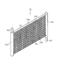
- FIG. 1 Schematic view of the appearance of the refrigerator for refrigeration (evaporator) Diagram showing the structure of a flat tube
- positioning aspect of the refrigerator for refrigeration The figure which shows typically the arrangement
- positioning aspect of the cooler for refrigeration typically 2 Figure 3 schematically showing the arrangement of the refrigeration cooler
- 1 schematically showing another structure of a refrigerator for refrigeration Figure 2 schematically showing another structure of the refrigerator for refrigeration
- Figure 2 schematically showing the location of the refrigerator for refrigeration Figure 3 schematically showing the location of the refrigerator for refrigeration
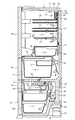
- the refrigerator 1 has a plurality of storage chambers arranged side by side in a vertical direction in a heat insulating box 2 having a vertically long rectangular box shape with an open front.
- a refrigeration room 3 and a vegetable room 4 are provided as storage rooms in order from the top, and an ice making room 5 and a small freezer room 6 are provided side by side on the lower side.
- a freezer compartment 7 is provided below these.
- a known automatic ice making device 8 (see FIG. 1) is provided in the ice making chamber 5.
- the heat insulating box 2 is basically composed of a steel plate outer box 2a, a synthetic resin inner box 2b, and a heat insulating material 2c provided between the outer box 2a and the inner box 2b. Yes.
- the refrigerator compartment 3 and the vegetable compartment 4 are both storage compartments in a refrigerated temperature zone (for example, 1 to 4 ° C.), and the refrigerator compartment 3 and the vegetable compartment 4 are partitioned vertically by a plastic partition wall 10. ing.
- a hinged heat insulating door 3 a is provided on the front surface of the refrigerator compartment 3.
- a drawer-type heat insulating door 4 a is provided on the front surface of the vegetable compartment 4.
- the lower case 11 which comprises a storage container is connected with the back surface part of the heat insulation door 4a.
- An upper case 12 that is smaller than the lower case 11 is provided at the rear of the upper portion of the lower case 11.
- the inside of the refrigerator compartment 3 is divided into a plurality of stages vertically by a plurality of shelf boards 13.
- a chilled chamber 14 is provided on the right side at the lowermost part (the upper part of the partition wall 10) in the refrigerator compartment 3, and egg cases and accessory cases are provided vertically on the left side thereof.
- a tank is provided.
- the water storage tank is for storing water to be supplied to the ice tray 8 a of the automatic ice making device 8.
- a chilled case 18 is provided in the chilled chamber 14 so that it can be taken in and out.
- the ice making room 5, the small freezing room 6 and the freezing room 7 are all storage rooms in a freezing temperature zone (for example, ⁇ 10 to ⁇ 20 ° C.). Further, the vegetable compartment 4 and the ice making compartment 5 and the small freezer compartment 6 are vertically partitioned by a heat insulating partition wall 19 as shown in FIG.
- a drawer-type heat insulating door 5 a is provided on the front surface of the ice making chamber 5.
- An ice storage container 20 is connected to the rear of the heat insulating door 5a.
- a drawer-type heat insulating door connected to a storage container is also provided on the front surface of the small freezer compartment 6.
- a drawer-type heat insulating door 7 a to which a storage container 22 is connected is also provided on the front surface of the freezer compartment 7.
- the refrigerator 1 incorporates a refrigeration cycle that includes two coolers, a refrigeration cooler 24 and a refrigeration cooler 25, although not shown in detail.
- the refrigerating cooler 24 generates cold air for cooling the refrigerating room 3 and the vegetable room 4, and is provided on the back surface of the refrigerator 1.
- the refrigeration cooler 24 is formed in a flat shape, and a flat tube 24c (see FIGS. 2 and 3) in which a plurality of channels through which a refrigerant flows is formed, and a flat tube 24c.
- the main body 24g (see FIG. 2) is formed in a substantially rectangular parallelepiped shape, and has a header 24a (see FIG. 2) serving as a refrigerant inlet and a header 24b (see FIG. 2) serving as a refrigerant outlet. It is a multi-flow type evaporator (evaporator).
- the freezer cooler 25 generates cold air for cooling the ice making room 5, the small freezer room 6, and the freezer room 7, and is provided at the back of the refrigerator 1 and below the refrigerating cooler 24. ing.
- a machine room 26 is provided on the lower back surface of the refrigerator 1. Although not shown in detail, this machine room 26 has a compressor 27, a condenser (not shown), and a cooling fan (not shown) for cooling the compressor 27 and the condenser constituting the above-described refrigeration cycle. ), A defrosted water evaporating dish 28 and the like are provided.
- the refrigeration cooler 25 also employs a multiflow evaporator.
- a control device 29 in which a microcomputer or the like for controlling the whole is mounted is provided near the lower rear portion of the refrigerator 1. Although not shown, the ground wire of the electric device provided in the refrigerator 1 is grounded via the outer box 2a or the like.
- a freezer cooler room 30 is provided on the back of the freezer room 7 in the refrigerator 1.
- a refrigeration cooler 25 In the refrigeration cooler chamber 30, a refrigeration cooler 25, a defrost heater (not shown), a refrigeration blower fan 31 serving as a blowing means, and the like are provided.
- the refrigeration blower fan 31 circulates the cold air generated by the refrigeration cooler 25 by generating air by the blowing action caused by the rotation of the fan, and is provided above the refrigeration cooler 25.
- a cold air outlet 30a is provided in the middle part of the front surface of the freezer cooler chamber 30, and a return port 30b is provided in the lower part.
- a refrigeration cooler 24, a cold air duct 34, a refrigeration blower fan 35 serving as a blowing means, and the like are provided behind the refrigeration room 3 and the vegetable room 4. That is, a refrigeration cooler chamber 36 that constitutes a part of the cold air duct 34 is provided behind the lowermost stage of the refrigeration chamber 3 in the refrigerator 1 (behind the chilled chamber 14). A refrigeration cooler 24 is provided therein.
- the cold air duct 34 forms a passage for supplying the cold air generated by the refrigerating cooler 24 to the refrigerating room 3 and the vegetable room 4.
- the refrigeration blower fan 35 circulates the cool air generated by the refrigeration cooler 24 by generating air by the blowing action caused by the rotation of the fan, and is provided below the refrigeration cooler 24.
- a cold air supply duct 37 extending upward is provided above the refrigerating cooler chamber 36, and the upper end portion of the refrigerating cooler chamber 36 communicates with the lower end portion of the cold air supply duct 37.
- the cold air duct 34 is constituted by the refrigeration cooler chamber 36 and the cold air supply duct 37.
- the front wall 36 a of the refrigeration cooler chamber 36 bulges forward from the cold air supply duct 37.
- a heat insulating material 38 having heat insulation covering the front surface of the refrigeration cooler 24 is provided on the back side (the refrigeration cooler 24 side) of the front wall 36a.
- a plurality of cold air supply ports 39 that open into the refrigerator compartment 3 are provided.
- a drainage basin 40 is provided in the lower part of the refrigeration cooler chamber 36 and below the refrigeration cooler 24.
- the drainage basin 40 receives defrosted water from the refrigeration cooler 24.
- the defrost water received by the drainage basin 40 is guided to the defrosting water evaporating dish 28 provided in the machine room 26 in the same manner as the defrosting water received by the drainage basin 32, and the defrosting water evaporating dish is provided. It is evaporated at 28.
- the left and right length dimensions and the front and rear depth dimensions of the drainage basin 40 are larger than the left and right length dimensions and the front and rear depth dimensions of the refrigeration cooler 24, and receive all the defrost water dripping from the refrigeration cooler 24. It is configured in the size that can be.
- a ventilation duct 42 is provided behind the vegetable room 4.
- a refrigeration blower fan 35 serving as a blower is provided in the blower duct 42.
- the air duct 42 has a suction port 43 at its lower end, and communicates with the refrigeration cooler chamber 36 (cold air duct 34) so that the upper end of the air duct 42 bypasses the drain 40.
- the suction port 43 is open in the vegetable compartment 4.
- a plurality of communication ports communicating with the vegetable compartment 4 are formed at the left and right corners of the rear part of the partition wall 10 that constitutes the bottom of the refrigerator compartment 3.
- the air blown into the refrigerator compartment 3 is also supplied into the vegetable compartment 4 through the communication port 44 and is finally sucked into the refrigerator fan 35 for refrigerator. In this way, the wind is circulated by the blowing action of the refrigeration blower fan 35.
- the refrigeration cycle is driven during the wind circulation process, the air passing through the refrigeration cooler chamber 36 is cooled by the refrigeration cooler 24 to become cold air, and the cold air is stored in the refrigerator compartment 3 and the vegetable compartment 4. , The refrigerator compartment 3 and the vegetable compartment 4 are cooled to temperatures in the refrigerator temperature zone.
- a water storage container 56 constituting a water storage section is provided at the front part of the lower part in the refrigeration cooler chamber 36.
- the water storage container 56 is provided between the refrigeration cooler 24 and the drain 40 and below the water supply unit 53.
- the front part of the water storage container 56 is attached to the front part wall 36a of the refrigerator room 36 for refrigeration, and is provided in the cantilever state which protrudes back.
- the water storage container 56 receives and stores defrost water dripped from the refrigeration cooler 24.
- a header 24a serving as a refrigerant inlet, a header 24b serving as a refrigerant outlet, a flat tube 24c connecting the header 24a and the header 24b, and the flat tubes 24c are provided.
- the main body 24g which is a portion where the flat tube 24c is provided, has a rectangular parallelepiped shape.
- the header 24a and the header 24b are formed in a hollow cylindrical shape, and the respective hollow portions (not shown) are in communication with each flat tube 24c. More specifically, as shown in FIG. 3, the flat tube 24c has a flat outer shape and a plurality of flow paths 24h through which the refrigerant flows. And each hollow part of the header 24a and the header 24b is connected by each flow path 24h.
- the contact area between the refrigerant and the flat tube 24c is increased as compared with the conventional type in which one large flow path is provided. Thereby, heat is efficiently transferred from the refrigerant to the flat tube 24c. Further, since the flat tubes 24c and the fins 24d are in contact, heat is efficiently transferred from the flat tubes 24c to the fins 24d. Since the fins 24d are formed in a wave shape, the contact area with air, that is, the heat exchange area can be further increased.
- the multi-flow type refrigeration cooler 24 can efficiently exchange heat with air.
- the refrigeration cooler 24 has the same volume, it can be expected to have an endothermic effect that is two to three times that of a conventional fin tube type, while it is only required to obtain the same endothermic effect.
- the volume can be greatly reduced, such as being thin.
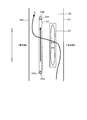
- the refrigerator 24 for refrigeration is arranged such that the inlet-side header 24a is on the lower side and the outlet-side header 24b is on the upper side.
- the refrigeration cooler 24 is disposed such that the main body 24g, which is a portion where the flat tube 24c is disposed, is perpendicular to the installation surface of the refrigerator 1, and the flat tube 24c is also disposed on the installation surface. It is arrange
- the term “perpendicular” here is not limited to a state of 90 degrees with respect to the installation surface, but includes a state that can be regarded as being substantially vertical, for example, a state that is slightly inclined.
- the refrigerant flowing into the refrigeration cooler 24 flows into the refrigeration cooler 24 in a liquid state from the inlet side connection portion 24e as indicated by an arrow F, and evaporates in the refrigeration cooler 24 to become a gas state. After that, the gas mainly flows out from the upper outlet side connection portion 24f. At this time, since the refrigerant in the liquid state flows down due to gravity, the refrigerant moves by installing the refrigerant at the lower side and installing the outlet at the upper side as schematically shown in FIG. Can be made smooth and efficient heat exchange can be performed.
- 4B schematically shows a state where the refrigeration cooler 24 shown in FIG. 4A is viewed from the left side in the figure.
- the refrigeration cooler 24 decreases in temperature and generates frost. Since this frost reduces the heat exchange performance, a defrosting process for removing the frost is performed, for example, at regular intervals. In this defrosting process, the attached frost is melted and discharged downward as defrosted water. Therefore, the flow of the defrost water can be promoted by arranging the main body 24g of the refrigeration cooler 24 vertically as in this embodiment. Furthermore, by arranging the flat tube 24c so as to be vertical, the defrost water is easily transmitted through the flat tube 24c, and can further promote the flow down.
- the refrigerator 1 performs heat exchange of the refrigeration cycle using a multi-flow type refrigeration cooler 24 (evaporator) having a flat tube 24c in which a plurality of flow paths 24h through which refrigerant flows are formed.
- a multi-flow type refrigeration cooler 24 evaporator
- a flat tube 24c in which a plurality of flow paths 24h through which refrigerant flows are formed.
- the multi-flow type refrigeration cooler 24 has a high heat exchange performance as described above, and the volume can be greatly reduced as compared with the conventional fin tube type if the performance is the same. Further, since the thickness can be reduced, the degree of freedom of the arrangement location is also improved. Therefore, the freedom degree of arrangement
- the flow of the defrost water can be promoted by arranging the main body 24g of the refrigeration cooler 24 vertically.
- the defrost water is easily transmitted through the flat tubes 24c, and the flow of the defrost water can be further promoted.
- the refrigeration cooler 24 and the refrigeration cooler 25 can be defrosted every cycle for each operation cycle. .
- the refrigerating cooler 24 is cooled if the refrigerant is flowing, while the internal temperature of the refrigerating chamber 3 is 0 ° C. or higher. Therefore, if the refrigerant is not flowing, the refrigerating fan 35 is kept running. Eva can be warmed and defrosted.
- the defrosting time is shorter than that of the conventional fin tube type, and an efficient operation can be achieved, thereby saving power. it can.
- the inlet side connecting portion 24e and the outlet side connecting portion 24f are provided substantially in parallel with the main body portion 24g, the length (thickness) in the front-rear direction of the refrigeration cooler 24 can be reduced, and the storage chamber Can be increased.
- the defrost water flows down on the lower side of the refrigeration cooler 24, if the refrigeration blower fan 35 is disposed in the range (flow area (Rx, see FIG. 7)), the defrost treatment is performed. When it is performed, there is a possibility that the defrost water is applied to the refrigeration blower fan 35.
- the fan 60 for sending air to the refrigeration cooler 24 is arranged at a position substantially parallel to the refrigeration cooler 24. It is possible to do.
- the fan 60 may be the refrigeration blower fan 35.
- the multi-flow type refrigeration cooler 24 can be thinned as described above, and therefore can be provided with the fan 60 in the refrigeration cooler chamber 36.
- the fan 60 is arranged on the upstream side of the wind flow, that is, on the windward side with respect to the refrigeration cooler 24. Thereby, even if the frost generated in the refrigeration cooler 24 is scattered or evaporated, it is possible to prevent moisture from being applied to the fan 60.
- the fan 60 when arranged in the cold air duct 34 as shown in FIG. 6, the fan 60 can be arranged above the refrigeration cooler 24. Thereby, it can prevent that defrost water applies to the fan 60.
- FIG. In this case, although the air sucked from the lower side passes through the refrigeration cooler 24 as indicated by an arrow B, it is considered that the scattered water droplets move downward due to gravity. The risk of 60 is reduced.
- the defrost water flow area (Rx) that is, a position that is substantially out of the range immediately below the refrigeration cooler 24. It is considered that defrost water can be prevented from being applied to the fan 60.
- the fan 60 may be disposed on the side opposite to the wind direction when passing through the refrigeration cooler 24 with respect to the refrigeration cooler 24.
- the direction of the wind when passing through the refrigeration cooler 24 is leftward in the figure, and therefore, the fan 60 may be positioned on the right side of the refrigeration cooler 24 in the figure. Thereby, even if the frost adhering to the surface of the refrigeration cooler 24 is blown off by the wind, the risk of being applied to the fan 60 can be reduced.
- the refrigeration cooler 24 can be disposed at an arbitrary position as long as it is outside the flow area of the defrost water. Therefore, for example, in FIG. 6, if there is a space in the horizontal direction in the figure, the fan 60 can be disposed obliquely above the refrigeration cooler 24.
- the refrigerator 24 for refrigeration can be arrange
- the term “horizontal” includes a state that can be regarded as being almost horizontal, for example, a state that is slightly inclined.
- the main body portion 24g can be thinned to improve the degree of freedom of installation and reduce the required space.
- the wind direction is upward, that is, the direction from the refrigeration cooler 24 toward the fan 60, but the frost peeled off from the refrigeration cooler 24 moves downward due to gravity, so the wind direction is a problem. None become.
- the meandering refrigeration cooler 24 has a configuration in which the refrigerant is connected from the inlet to the outlet while folding one flat tube 24c.
- the flat tube 24c is provided with a header 24a on the refrigerant inlet side and a header 24b on the refrigerant outlet side.
- a fin 24d is provided between the folded flat tubes 24c.
- the heat exchange performance is high and the same performance as in the parallel type shown in the first aspect, compared to the conventional fin tube type.
- the volume can be greatly reduced and the thickness can be reduced, so that the degree of freedom of the arrangement location is also improved, so that an effective internal volume usable as a storage room can be earned.
- the refrigeration cooler 24 flows in the liquid state refrigerant and flows out in the gaseous state. At this time, there may be a so-called liquid back in which the refrigerant that cannot be evaporated flows out in a liquid state.
- FIG. 10 schematically shows a difference in volume due to a difference in diameter between the header 24a and the header 24b.
- the header 24b on the outlet side functions like an accumulator, and the possibility that the refrigerant circulates in the liquid state on the rear stage side of the refrigeration cooler 24 can be reduced. If a sufficient volume can be secured, accumulator-less operation can be achieved.
- the refrigerator 24 for refrigeration can also be arrange
- the refrigeration cooler 24 can be disposed inside the refrigerator 1 on the ceiling side and the back side (hereinafter referred to as the upper back side for convenience).
- the upper back side of the refrigerator 1 is a place that is relatively difficult to reach when putting food into and out of the refrigerator compartment 3 depending on the size of the refrigerator 1. Further, since the multi-flow type refrigeration cooler 24 is downsized as described above, the required space is also reduced.
- the refrigeration cooler 24 and the refrigeration blower fan 35 are provided side by side (see FIG. 5) and arranged on the upper back side, so that an empty space is provided behind the vegetable compartment 4 in this embodiment. Therefore, the vegetable compartment 4 can also be enlarged.
- the vegetable compartment 4 may be enlarged. it can.
- the refrigeration cooler 24 and the refrigeration blower fan 35 are provided side by side (see FIG. 5) and arranged behind the chilled chamber 14, the vegetable compartment 4 may be enlarged. it can.
- the refrigeration cooler 24 not only the refrigeration cooler 24 but also the refrigeration blower fan 35 can be arranged and the degree of freedom is improved.
- the effective internal volume which can be used as a storage room can be earned, such as being able to effectively utilize the upper back side where it is difficult to put in and out food.
- the same effect as that of the refrigeration cooler 24 can be obtained for the refrigeration cooler 25.
- the cooling with a single cooler requires the cold air duct to be routed, and the internal volume that can be used as the storage chamber decreases accordingly.
- the conventional finned-tube type cooler has a certain size, so that the internal volume is also reduced. End up.
- a plurality of multiflow evaporators having a flat tube 24c in which a plurality of flow paths through which a refrigerant flows are formed are used for cooling the storage chamber in the same temperature range.
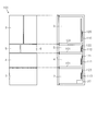
- FIG. 14 schematically shows the refrigerator 100 of this aspect.
- the refrigerator compartment 3 is provided on the uppermost side
- the ice making chamber 5 and the small freezer compartment 6 are provided side by side on the lower side
- the vegetable compartment 4 is provided below these
- the freezer is placed on the lower side.
- a chamber 7 is provided.
- the refrigerator compartment 3 and the vegetable compartment 4 are storage compartments in a refrigerated temperature zone, that is, roughly the same temperature zone
- the ice making chamber 5, the small freezer compartment 6 and the freezer compartment 7 are storage compartments in a freezing temperature zone. In other words, it is a storage room of almost the same temperature range.
- the refrigerator 100 includes a first R cooler 110 for cooling the refrigerator compartment 3, a second R cooler 111 for cooling the vegetable compartment 4, the first ice cooling for cooling the ice making chamber 5 and the small freezer compartment 6. And a second F cooler 113 for cooling the freezer compartment 7. Further, the storage rooms are partitioned by a heat insulating partition 101.
- the multi-flow type evaporator can be expected to have a heat absorption effect of 2 to 3 times as long as the volume is the same as that of the conventional fin tube type, while it is only required to obtain the same endothermic effect as the conventional one. If it is, it will become possible to reduce in size and thickness, and a required installation space can be reduced significantly. Therefore, by using a plurality of multi-flow type evaporators for the storage chamber in the same temperature range, it is possible to suppress a large decrease in the internal volume. That is, the multiflow type cooler (evaporator) can be reduced in thickness and size as compared with the conventional fin tube type cooler.
- the first R cooler 110, the second R cooler 111, the first F cooler 112, and the second F cooler 113 are provided with blower fans 120 to 122, respectively. Thereby, the heat exchange in each cooler can be promoted, and the endothermic effect can be improved.
- FIG. 15 schematically shows a connection mode when the coolers are connected in series.
- the first R cooler 110 and the second R cooler 111 are connected to the upstream side in the path through which the refrigerant for the refrigeration temperature zone switched by the switching valve 104 configured by, for example, a three-way valve flows.
- the second R cooler 111 is connected to the downstream side.
- first F cooler 112 and the second F cooler 113 are connected to the upstream side of the first F cooler 112 in the path through which the refrigerant for the refrigeration temperature zone switched by the switching valve 104 flows.
- a 2F cooler 113 is connected. These coolers constitute a refrigeration cycle 105 together with the compressor 27 and the condenser 103.
- FIG. 16 schematically shows a connection mode when the coolers are connected in parallel.
- the path through which the refrigerant flows by the switching valve 104 including a five-way valve or a plurality of three-way valves is the first R cooler 110, the second R cooler 111, the first F cooler 112, and the second F cooler 113. Can be switched individually.
- each cooler can be individually switched, and each cooler can be operated at an appropriate evaporation temperature, saving energy. Can be promoted.
- each cooler cools a separate storage room.
- the storage room of the same temperature zone is cooled with a single cooler as in the prior art, for example, when the refrigerator compartment 3 is cooled, the vegetable compartment 4 is inevitably cooled. Therefore, although the vegetable compartment 4 may be cooled even if the vegetable compartment 4 is not opened and closed, for example, the doors of the refrigerator compartment 3 can be cooled by cooling separate storage compartments with individual coolers. Even when the temperature of the refrigerator compartment 3 is increased by opening and closing, only the refrigerator compartment 3 can be cooled. That is, each storage room can be individually maintained at an appropriate temperature. Moreover, since the compact cooler is used, the influence on the internal volume can be kept small.
- the structure of the storage room of the refrigerator 100 shown in FIG. 14 is an example.
- the order of the vegetable room 4 and the freezing room 7 is changed, and the refrigerator room 3 is arranged at the top and the vegetable room 4 is arranged at the bottom. It can also be set as the structure which arranged.
- the refrigerator compartment 3 and the vegetable compartment 4 which are arranged apart from each other are cooled by separate coolers, and the ice making compartment 5, the small freezer compartment 6 and the freezer compartment 7 which are arranged adjacent to each other are one. It can also be set as the structure cooled with a cooler.
- the storage room in the refrigeration temperature range can be efficiently cooled. It can be carried out.
- the structure illustrated by this aspect is applicable.
- a third R cooler 114 is provided in the chilled chamber 14, and the refrigerated chamber 3, the vegetable chamber 4, and the chilled chamber 14 are provided.
- Each can be individually cooled.
- food can be stored in a more appropriate temperature range, and convenience can be improved. That is, it can be set as the structure which provides 3 or more of storage rooms of the same temperature range.
- the multi-flow type evaporator having the headers 24a and 24b has been exemplified.
- the external pipe can be directly connected to the flat tube 24c without using the header 24a or the like.
- the direction in which the inlet side connection part 24e and the outlet side connection part 24f extend is not limited to the direction illustrated in the embodiment.
- the inlet side connecting portion 24e and the outlet side connecting portion 24f are arranged in the vertical direction, that is, in the direction extending in the thickness direction of the fan 60. can do. Thereby, space saving can be achieved by arranging the fan 60 within the range of the length of the inlet side connection part 24e and the outlet side connection part 24f.
Landscapes
- Engineering & Computer Science (AREA)
- Physics & Mathematics (AREA)
- Mechanical Engineering (AREA)
- Thermal Sciences (AREA)
- General Engineering & Computer Science (AREA)
- Chemical & Material Sciences (AREA)
- Combustion & Propulsion (AREA)
- Cold Air Circulating Systems And Constructional Details In Refrigerators (AREA)
Priority Applications (1)
| Application Number | Priority Date | Filing Date | Title |
|---|---|---|---|
| CN201880008804.2A CN110226074A (zh) | 2017-03-03 | 2018-01-22 | 冰箱 |
Applications Claiming Priority (2)
| Application Number | Priority Date | Filing Date | Title |
|---|---|---|---|
| JP2017-040421 | 2017-03-03 | ||
| JP2017040421A JP6955348B2 (ja) | 2017-03-03 | 2017-03-03 | 冷蔵庫 |
Publications (1)
| Publication Number | Publication Date |
|---|---|
| WO2018159151A1 true WO2018159151A1 (ja) | 2018-09-07 |
Family
ID=63370403
Family Applications (1)
| Application Number | Title | Priority Date | Filing Date |
|---|---|---|---|
| PCT/JP2018/001785 WO2018159151A1 (ja) | 2017-03-03 | 2018-01-22 | 冷蔵庫 |
Country Status (4)
| Country | Link |
|---|---|
| JP (1) | JP6955348B2 (zh) |
| CN (1) | CN110226074A (zh) |
| TW (1) | TWI658245B (zh) |
| WO (1) | WO2018159151A1 (zh) |
Citations (9)
| Publication number | Priority date | Publication date | Assignee | Title |
|---|---|---|---|---|
| JPS5245864U (zh) * | 1975-09-27 | 1977-03-31 | ||
| JP2003194448A (ja) * | 2001-12-26 | 2003-07-09 | Mitsubishi Electric Corp | 冷蔵庫 |
| JP2003314945A (ja) * | 2002-04-18 | 2003-11-06 | Matsushita Refrig Co Ltd | 冷蔵庫 |
| JP2004028354A (ja) * | 2002-06-21 | 2004-01-29 | Hitachi Home & Life Solutions Inc | 冷蔵庫 |
| JP2005114345A (ja) * | 2003-10-10 | 2005-04-28 | Hussmann Corp | 冷蔵マーチャンダイザー用蒸発器 |
| JP2007333299A (ja) * | 2006-06-14 | 2007-12-27 | Toshiba Corp | 冷蔵庫 |
| JP2008020159A (ja) * | 2006-07-14 | 2008-01-31 | Toshiba Corp | 冷蔵庫 |
| KR20110085603A (ko) * | 2010-01-21 | 2011-07-27 | 엘지전자 주식회사 | 냉장고 |
| US20130098081A1 (en) * | 2011-10-24 | 2013-04-25 | Whirlpool Corporation | Higher efficiency appliance employing thermal load shifting in refrigerators having horizontal mullion |
Family Cites Families (4)
| Publication number | Priority date | Publication date | Assignee | Title |
|---|---|---|---|---|
| KR20070054531A (ko) * | 2005-11-23 | 2007-05-29 | 엘지전자 주식회사 | 냉장고 |
| TWM468663U (zh) * | 2013-06-07 | 2013-12-21 | Man Zai Ind Co Ltd | 具微通道之熱交換器 |
| JP6261432B2 (ja) * | 2014-04-03 | 2018-01-17 | 三菱電機株式会社 | 冷蔵庫 |
| CN205245622U (zh) * | 2015-11-30 | 2016-05-18 | 河南新飞电器有限公司 | 一种多流路微通道冷凝器 |
-
2017
- 2017-03-03 JP JP2017040421A patent/JP6955348B2/ja active Active
-
2018
- 2018-01-08 TW TW107100587A patent/TWI658245B/zh not_active IP Right Cessation
- 2018-01-22 CN CN201880008804.2A patent/CN110226074A/zh active Pending
- 2018-01-22 WO PCT/JP2018/001785 patent/WO2018159151A1/ja active Application Filing
Patent Citations (9)
| Publication number | Priority date | Publication date | Assignee | Title |
|---|---|---|---|---|
| JPS5245864U (zh) * | 1975-09-27 | 1977-03-31 | ||
| JP2003194448A (ja) * | 2001-12-26 | 2003-07-09 | Mitsubishi Electric Corp | 冷蔵庫 |
| JP2003314945A (ja) * | 2002-04-18 | 2003-11-06 | Matsushita Refrig Co Ltd | 冷蔵庫 |
| JP2004028354A (ja) * | 2002-06-21 | 2004-01-29 | Hitachi Home & Life Solutions Inc | 冷蔵庫 |
| JP2005114345A (ja) * | 2003-10-10 | 2005-04-28 | Hussmann Corp | 冷蔵マーチャンダイザー用蒸発器 |
| JP2007333299A (ja) * | 2006-06-14 | 2007-12-27 | Toshiba Corp | 冷蔵庫 |
| JP2008020159A (ja) * | 2006-07-14 | 2008-01-31 | Toshiba Corp | 冷蔵庫 |
| KR20110085603A (ko) * | 2010-01-21 | 2011-07-27 | 엘지전자 주식회사 | 냉장고 |
| US20130098081A1 (en) * | 2011-10-24 | 2013-04-25 | Whirlpool Corporation | Higher efficiency appliance employing thermal load shifting in refrigerators having horizontal mullion |
Also Published As
| Publication number | Publication date |
|---|---|
| TW201833497A (zh) | 2018-09-16 |
| JP2018146158A (ja) | 2018-09-20 |
| CN110226074A (zh) | 2019-09-10 |
| JP6955348B2 (ja) | 2021-10-27 |
| TWI658245B (zh) | 2019-05-01 |
Similar Documents
| Publication | Publication Date | Title |
|---|---|---|
| US8261573B2 (en) | Refrigerator | |
| JP5872143B2 (ja) | 冷蔵庫 | |
| JP2009133504A (ja) | 冷凍冷蔵庫 | |
| JP2008249292A (ja) | 冷蔵庫 | |
| US7950247B2 (en) | Refrigerator related technology | |
| JP5450462B2 (ja) | 冷蔵庫 | |
| JP7369434B2 (ja) | 冷蔵庫 | |
| JP2012127629A (ja) | 冷却貯蔵庫 | |
| JP2021076296A (ja) | 冷蔵庫 | |
| JP7032055B2 (ja) | 冷蔵庫 | |
| JP2014048031A (ja) | 冷蔵庫 | |
| JP2015102320A (ja) | 冷蔵庫 | |
| JP5916174B2 (ja) | 冷蔵庫 | |
| JP2014077615A (ja) | 冷蔵庫 | |
| JP2008111640A (ja) | 冷蔵庫 | |
| WO2018159151A1 (ja) | 冷蔵庫 | |
| JP2005345061A (ja) | 冷蔵庫 | |
| JP6940424B2 (ja) | 冷蔵庫 | |
| WO2010092625A1 (ja) | 冷蔵庫 | |
| JP2021101136A (ja) | 冷蔵庫 | |
| JP2005016903A (ja) | 冷蔵庫 | |
| JP5990731B2 (ja) | 冷蔵庫 | |
| JP6139286B2 (ja) | 冷蔵庫 | |
| JP2013096607A (ja) | 冷蔵庫 | |
| JP4203662B2 (ja) | 冷蔵庫 |
Legal Events
| Date | Code | Title | Description |
|---|---|---|---|
| 121 | Ep: the epo has been informed by wipo that ep was designated in this application |
Ref document number: 18760538 Country of ref document: EP Kind code of ref document: A1 |
|
| NENP | Non-entry into the national phase |
Ref country code: DE |
|
| 122 | Ep: pct application non-entry in european phase |
Ref document number: 18760538 Country of ref document: EP Kind code of ref document: A1 |