WO2018159151A1 - Refrigerator - Google Patents
Refrigerator Download PDFInfo
- Publication number
- WO2018159151A1 WO2018159151A1 PCT/JP2018/001785 JP2018001785W WO2018159151A1 WO 2018159151 A1 WO2018159151 A1 WO 2018159151A1 JP 2018001785 W JP2018001785 W JP 2018001785W WO 2018159151 A1 WO2018159151 A1 WO 2018159151A1
- Authority
- WO
- WIPO (PCT)
- Prior art keywords
- cooler
- refrigeration
- refrigerator
- room
- refrigeration cooler
- Prior art date
Links
- 235000013311 vegetables Nutrition 0.000 claims abstract description 34
- 239000003507 refrigerant Substances 0.000 claims abstract description 33
- 238000001816 cooling Methods 0.000 claims abstract description 18
- 238000005057 refrigeration Methods 0.000 claims description 158
- 238000007710 freezing Methods 0.000 claims description 11
- 230000008014 freezing Effects 0.000 claims description 11
- XLYOFNOQVPJJNP-UHFFFAOYSA-N water Substances O XLYOFNOQVPJJNP-UHFFFAOYSA-N 0.000 description 37
- 230000000694 effects Effects 0.000 description 9
- 238000009434 installation Methods 0.000 description 9
- 238000007664 blowing Methods 0.000 description 7
- 238000001704 evaporation Methods 0.000 description 6
- 239000007788 liquid Substances 0.000 description 6
- 238000005192 partition Methods 0.000 description 6
- 238000010257 thawing Methods 0.000 description 6
- 230000009471 action Effects 0.000 description 5
- 230000005484 gravity Effects 0.000 description 4
- 238000009413 insulation Methods 0.000 description 4
- 238000004891 communication Methods 0.000 description 3
- 230000007423 decrease Effects 0.000 description 3
- 235000013305 food Nutrition 0.000 description 3
- 238000000034 method Methods 0.000 description 3
- 230000008569 process Effects 0.000 description 3
- 238000011144 upstream manufacturing Methods 0.000 description 3
- 239000011810 insulating material Substances 0.000 description 2
- 229910000831 Steel Inorganic materials 0.000 description 1
- 238000010521 absorption reaction Methods 0.000 description 1
- 238000010586 diagram Methods 0.000 description 1
- 230000008020 evaporation Effects 0.000 description 1
- 239000007769 metal material Substances 0.000 description 1
- 238000012986 modification Methods 0.000 description 1
- 230000004048 modification Effects 0.000 description 1
- 230000009467 reduction Effects 0.000 description 1
- 239000010959 steel Substances 0.000 description 1
- 229920003002 synthetic resin Polymers 0.000 description 1
- 239000000057 synthetic resin Substances 0.000 description 1
- 238000009423 ventilation Methods 0.000 description 1
Images


Classifications
-
- F—MECHANICAL ENGINEERING; LIGHTING; HEATING; WEAPONS; BLASTING
- F25—REFRIGERATION OR COOLING; COMBINED HEATING AND REFRIGERATION SYSTEMS; HEAT PUMP SYSTEMS; MANUFACTURE OR STORAGE OF ICE; LIQUEFACTION SOLIDIFICATION OF GASES
- F25B—REFRIGERATION MACHINES, PLANTS OR SYSTEMS; COMBINED HEATING AND REFRIGERATION SYSTEMS; HEAT PUMP SYSTEMS
- F25B5/00—Compression machines, plants or systems, with several evaporator circuits, e.g. for varying refrigerating capacity
- F25B5/02—Compression machines, plants or systems, with several evaporator circuits, e.g. for varying refrigerating capacity arranged in parallel
-
- F—MECHANICAL ENGINEERING; LIGHTING; HEATING; WEAPONS; BLASTING
- F25—REFRIGERATION OR COOLING; COMBINED HEATING AND REFRIGERATION SYSTEMS; HEAT PUMP SYSTEMS; MANUFACTURE OR STORAGE OF ICE; LIQUEFACTION SOLIDIFICATION OF GASES
- F25B—REFRIGERATION MACHINES, PLANTS OR SYSTEMS; COMBINED HEATING AND REFRIGERATION SYSTEMS; HEAT PUMP SYSTEMS
- F25B5/00—Compression machines, plants or systems, with several evaporator circuits, e.g. for varying refrigerating capacity
- F25B5/04—Compression machines, plants or systems, with several evaporator circuits, e.g. for varying refrigerating capacity arranged in series
-
- F—MECHANICAL ENGINEERING; LIGHTING; HEATING; WEAPONS; BLASTING
- F25—REFRIGERATION OR COOLING; COMBINED HEATING AND REFRIGERATION SYSTEMS; HEAT PUMP SYSTEMS; MANUFACTURE OR STORAGE OF ICE; LIQUEFACTION SOLIDIFICATION OF GASES
- F25D—REFRIGERATORS; COLD ROOMS; ICE-BOXES; COOLING OR FREEZING APPARATUS NOT OTHERWISE PROVIDED FOR
- F25D17/00—Arrangements for circulating cooling fluids; Arrangements for circulating gas, e.g. air, within refrigerated spaces
- F25D17/04—Arrangements for circulating cooling fluids; Arrangements for circulating gas, e.g. air, within refrigerated spaces for circulating air, e.g. by convection
- F25D17/06—Arrangements for circulating cooling fluids; Arrangements for circulating gas, e.g. air, within refrigerated spaces for circulating air, e.g. by convection by forced circulation
-
- F—MECHANICAL ENGINEERING; LIGHTING; HEATING; WEAPONS; BLASTING
- F25—REFRIGERATION OR COOLING; COMBINED HEATING AND REFRIGERATION SYSTEMS; HEAT PUMP SYSTEMS; MANUFACTURE OR STORAGE OF ICE; LIQUEFACTION SOLIDIFICATION OF GASES
- F25D—REFRIGERATORS; COLD ROOMS; ICE-BOXES; COOLING OR FREEZING APPARATUS NOT OTHERWISE PROVIDED FOR
- F25D19/00—Arrangement or mounting of refrigeration units with respect to devices or objects to be refrigerated, e.g. infrared detectors
Landscapes
- Engineering & Computer Science (AREA)
- Physics & Mathematics (AREA)
- Mechanical Engineering (AREA)
- Thermal Sciences (AREA)
- General Engineering & Computer Science (AREA)
- Chemical & Material Sciences (AREA)
- Combustion & Propulsion (AREA)
- Cold Air Circulating Systems And Constructional Details In Refrigerators (AREA)
Abstract
For cooling a refrigerator compartment 3 and a vegetable compartment 4 that are storage compartments in the same temperature zone and a small freezer compartment 6 and a freezer compartment 7 that are storage compartments in the same temperature zone, this refrigerator 100 uses a plurality of multi-flow type evaporators (first R cooler 110, second R cooler 111, first F cooler 112, and second F cooler 113) that have flat tubes in which a plurality of flow paths in which refrigerant flows are formed.
Description
本発明の実施形態は、冷蔵庫に関する。
Embodiment of this invention is related with a refrigerator.
従来、冷蔵庫では、コンプレッサ、コンデンサおよびエバポレータ等で構成された冷凍サイクルにより貯蔵室を冷却することが行われている。このとき、エバポレータは、例えば貯蔵室の背面側のダクトに設けられることがある(例えば、特許文献1参照)。
Conventionally, in a refrigerator, a storage room is cooled by a refrigeration cycle including a compressor, a condenser, an evaporator, and the like. At this time, the evaporator may be provided, for example, in a duct on the back side of the storage chamber (see, for example, Patent Document 1).
さて、特許文献1のように冷蔵庫の背面側にエバポレータを配置する場合、エバポレータの本体部を垂直に配置することで設置スペースの前後方向の長さを短くするようにしているものの、吸熱量を稼ぐためにはエバポレータの上下方向もある程度の長さが必要になることから、エバポレータによって占有されるスペースが大きくなっていた。その結果、貯蔵室の奥行きを確保するためにはエバポレータの上部もしくは下部にファンを配置せざるを得ず、背面側に大きなデッドスペースつまりは貯蔵室として利用できないスペースが存在していた。
Now, when the evaporator is arranged on the back side of the refrigerator as in Patent Document 1, the length of the installation space in the front-rear direction is shortened by vertically arranging the main body of the evaporator. In order to earn, a certain length is required in the vertical direction of the evaporator, so that the space occupied by the evaporator has been increased. As a result, in order to secure the depth of the storage room, a fan has to be arranged above or below the evaporator, and there is a large dead space on the back side, that is, a space that cannot be used as a storage room.
そこで、貯蔵室として利用可能な有効な庫内体積を稼ぐことができる冷蔵庫を提供する。
Therefore, a refrigerator capable of earning an effective internal volume that can be used as a storage room is provided.
実施形態の冷蔵庫は、同一温度帯の貯蔵室の冷却用に、内部に冷媒が流れる流路が複数形成された偏平管を有するマルチフロー型のエバポレータを複数用いる。
The refrigerator of the embodiment uses a plurality of multi-flow type evaporators having a flat tube in which a plurality of channels through which a refrigerant flows are formed for cooling a storage room in the same temperature range.
(第1実施形態)
以下、実施形態について、図面を参照しながら説明する。なお、説明の簡略化のために、まず第1態様から第3態様としてマルチフロー型のエバポレータの構造や特徴ならびにそれを用いた冷蔵庫について説明し、その後、複数配置態様として複数のマルチフロー型のエバポレータを用いる具体例について説明する。 (First embodiment)
Hereinafter, embodiments will be described with reference to the drawings. For the sake of simplification of explanation, first, the structure and characteristics of a multi-flow type evaporator as a first to third aspect and a refrigerator using the same will be described, and then a plurality of multi-flow type as a plurality of arrangement aspects. A specific example using an evaporator will be described.
<第1態様>
以下、第1態様について、図1から図4を参照して説明する。
図1に示すように、冷蔵庫1は、前面が開口した縦長矩形箱状の断熱箱体2内に、上下方向に並んで配置された複数の貯蔵室を有している。具体的には、断熱箱体2内には、上段から順に、貯蔵室として、冷蔵室3、野菜室4が設けられ、その下方に製氷室5と小冷凍室6が左右に並べて設けられ、これらの下方に冷凍室7が設けられている。製氷室5内には、周知の自動製氷装置8(図1参照)が設けられている。断熱箱体2は、基本的には、鋼板製の外箱2aと、合成樹脂製の内箱2bと、外箱2aと内箱2bとの間に設けられた断熱材2cとから構成されている。 <First aspect>
Hereinafter, the first aspect will be described with reference to FIGS. 1 to 4.
As shown in FIG. 1, therefrigerator 1 has a plurality of storage chambers arranged side by side in a vertical direction in a heat insulating box 2 having a vertically long rectangular box shape with an open front. Specifically, in the heat insulation box 2, a refrigeration room 3 and a vegetable room 4 are provided as storage rooms in order from the top, and an ice making room 5 and a small freezer room 6 are provided side by side on the lower side. A freezer compartment 7 is provided below these. A known automatic ice making device 8 (see FIG. 1) is provided in the ice making chamber 5. The heat insulating box 2 is basically composed of a steel plate outer box 2a, a synthetic resin inner box 2b, and a heat insulating material 2c provided between the outer box 2a and the inner box 2b. Yes.
以下、第1態様について、図1から図4を参照して説明する。
図1に示すように、冷蔵庫1は、前面が開口した縦長矩形箱状の断熱箱体2内に、上下方向に並んで配置された複数の貯蔵室を有している。具体的には、断熱箱体2内には、上段から順に、貯蔵室として、冷蔵室3、野菜室4が設けられ、その下方に製氷室5と小冷凍室6が左右に並べて設けられ、これらの下方に冷凍室7が設けられている。製氷室5内には、周知の自動製氷装置8(図1参照)が設けられている。断熱箱体2は、基本的には、鋼板製の外箱2aと、合成樹脂製の内箱2bと、外箱2aと内箱2bとの間に設けられた断熱材2cとから構成されている。 <First aspect>
Hereinafter, the first aspect will be described with reference to FIGS. 1 to 4.
As shown in FIG. 1, the
冷蔵室3および野菜室4は、いずれも冷蔵温度帯(例えば1~4℃)の貯蔵室であり、冷蔵室3と野菜室4との間は、プラスチック製の仕切壁10により上下に仕切られている。冷蔵室3の前面部には、図1に示すように、ヒンジ開閉式の断熱扉3aが設けられている。野菜室4の前面部には、引出し式の断熱扉4aが設けられている。断熱扉4aの背面部には、貯蔵容器を構成する下部ケース11が連結されている。下部ケース11の上部の後部には、下部ケース11よりも小型の上部ケース12が設けられている。
The refrigerator compartment 3 and the vegetable compartment 4 are both storage compartments in a refrigerated temperature zone (for example, 1 to 4 ° C.), and the refrigerator compartment 3 and the vegetable compartment 4 are partitioned vertically by a plastic partition wall 10. ing. As shown in FIG. 1, a hinged heat insulating door 3 a is provided on the front surface of the refrigerator compartment 3. A drawer-type heat insulating door 4 a is provided on the front surface of the vegetable compartment 4. The lower case 11 which comprises a storage container is connected with the back surface part of the heat insulation door 4a. An upper case 12 that is smaller than the lower case 11 is provided at the rear of the upper portion of the lower case 11.
冷蔵室3内は、複数の棚板13により上下に複数段に区切られている。冷蔵室3内の最下部(仕切壁10の上部)には、右側にはチルド室14が設けられ、その左側には卵ケースおよび小物ケースが上下に設けられ、さらに、これらの左側には貯水タンクが設けられている。貯水タンクは、自動製氷装置8の製氷皿8aに供給する水を貯留するためのものである。チルド室14には、チルドケース18が出し入れ可能に設けられている。
The inside of the refrigerator compartment 3 is divided into a plurality of stages vertically by a plurality of shelf boards 13. A chilled chamber 14 is provided on the right side at the lowermost part (the upper part of the partition wall 10) in the refrigerator compartment 3, and egg cases and accessory cases are provided vertically on the left side thereof. A tank is provided. The water storage tank is for storing water to be supplied to the ice tray 8 a of the automatic ice making device 8. A chilled case 18 is provided in the chilled chamber 14 so that it can be taken in and out.
製氷室5、小冷凍室6および冷凍室7は、いずれも冷凍温度帯(例えば-10~-20℃)の貯蔵室である。また、野菜室4と、製氷室5および小冷凍室6との間は、図1に示すように断熱仕切壁19により上下に仕切られている。製氷室5の前面部には、引出し式の断熱扉5aが設けられている。断熱扉5aの後方には、貯氷容器20が連結されている。小冷凍室6の前面部にも、図示はしないが貯蔵容器が連結された引出し式の断熱扉が設けられている。冷凍室7の前面部にも、貯蔵容器22が連結された引出し式の断熱扉7aが設けられている。
The ice making room 5, the small freezing room 6 and the freezing room 7 are all storage rooms in a freezing temperature zone (for example, −10 to −20 ° C.). Further, the vegetable compartment 4 and the ice making compartment 5 and the small freezer compartment 6 are vertically partitioned by a heat insulating partition wall 19 as shown in FIG. A drawer-type heat insulating door 5 a is provided on the front surface of the ice making chamber 5. An ice storage container 20 is connected to the rear of the heat insulating door 5a. Although not shown, a drawer-type heat insulating door connected to a storage container is also provided on the front surface of the small freezer compartment 6. A drawer-type heat insulating door 7 a to which a storage container 22 is connected is also provided on the front surface of the freezer compartment 7.
冷蔵庫1には、詳しく図示はしないが、冷蔵用冷却器24および冷凍用冷却器25の2つの冷却器を備える冷凍サイクルが組み込まれている。冷蔵用冷却器24は、冷蔵室3および野菜室4を冷却するための冷気を生成するものであり、冷蔵庫1の背面部に設けられている。この冷蔵用冷却器24は、詳細は後述するが、偏平状に形成され、その内部に冷媒が流れる流路が複数形成されている偏平管24c(図2、図3参照)と、偏平管24cへの冷媒の入口となるヘッダ24a(図2参照)と、冷媒の出口となるヘッダ24b(図2参照)とを有し、本体部24g(図2参照)が概ね薄い直方体状に形成されたマルチフロー型のエバポレータ(蒸発器)である。
The refrigerator 1 incorporates a refrigeration cycle that includes two coolers, a refrigeration cooler 24 and a refrigeration cooler 25, although not shown in detail. The refrigerating cooler 24 generates cold air for cooling the refrigerating room 3 and the vegetable room 4, and is provided on the back surface of the refrigerator 1. As will be described in detail later, the refrigeration cooler 24 is formed in a flat shape, and a flat tube 24c (see FIGS. 2 and 3) in which a plurality of channels through which a refrigerant flows is formed, and a flat tube 24c. The main body 24g (see FIG. 2) is formed in a substantially rectangular parallelepiped shape, and has a header 24a (see FIG. 2) serving as a refrigerant inlet and a header 24b (see FIG. 2) serving as a refrigerant outlet. It is a multi-flow type evaporator (evaporator).
冷凍用冷却器25は、製氷室5、小冷凍室6および冷凍室7を冷却するための冷気を生成するものであり、冷蔵庫1の背面部であって冷蔵用冷却器24の下方に設けられている。冷蔵庫1の下部背面部には、機械室26が設けられている。詳しく図示はしないが、この機械室26内には、上述の冷凍サイクルを構成する圧縮機27、凝縮器(図示せず)、圧縮機27および凝縮器を冷却するための冷却ファン(図示せず)、除霜水蒸発皿28などが設けられている。また、冷凍用冷却器25も、マルチフロー型のエバポレータを採用している。
The freezer cooler 25 generates cold air for cooling the ice making room 5, the small freezer room 6, and the freezer room 7, and is provided at the back of the refrigerator 1 and below the refrigerating cooler 24. ing. A machine room 26 is provided on the lower back surface of the refrigerator 1. Although not shown in detail, this machine room 26 has a compressor 27, a condenser (not shown), and a cooling fan (not shown) for cooling the compressor 27 and the condenser constituting the above-described refrigeration cycle. ), A defrosted water evaporating dish 28 and the like are provided. The refrigeration cooler 25 also employs a multiflow evaporator.
冷蔵庫1の背面下部寄り部分には、全体を制御するマイコン等を実装した制御装置29が設けられている。なお、図示はしないが、冷蔵庫1に設けられる電気機器のアース線は、外箱2aなどを介して接地されている。
A control device 29 in which a microcomputer or the like for controlling the whole is mounted is provided near the lower rear portion of the refrigerator 1. Although not shown, the ground wire of the electric device provided in the refrigerator 1 is grounded via the outer box 2a or the like.
冷蔵庫1内の冷凍室7の背面部には、冷凍用冷却器室30が設けられている。冷凍用冷却器室30内には、冷凍用冷却器25、除霜用ヒータ(図示せず)、送風手段たる冷凍用送風ファン31などが設けられている。冷凍用送風ファン31は、ファンが回転することによる送風作用によって風を発生させて冷凍用冷却器25によって生成した冷気を循環させるものであり、冷凍用冷却器25の上方に設けられている。冷凍用冷却器室30の前面の中間部には、冷気吹出口30aが設けられ、下部には、戻り口30bが設けられている。
A freezer cooler room 30 is provided on the back of the freezer room 7 in the refrigerator 1. In the refrigeration cooler chamber 30, a refrigeration cooler 25, a defrost heater (not shown), a refrigeration blower fan 31 serving as a blowing means, and the like are provided. The refrigeration blower fan 31 circulates the cold air generated by the refrigeration cooler 25 by generating air by the blowing action caused by the rotation of the fan, and is provided above the refrigeration cooler 25. A cold air outlet 30a is provided in the middle part of the front surface of the freezer cooler chamber 30, and a return port 30b is provided in the lower part.
この構成において、冷凍用送風ファン31および冷凍サイクルが駆動されると、送風作用によって風が生成され、冷凍用冷却器25によって生成した冷気は、冷気吹出口30aから製氷室5、小冷凍室6、冷凍室7内に供給され、戻り口30bから冷凍用冷却器室30内に戻される循環をする。これにより、それら製氷室5、小冷凍室6および冷凍室7は冷却される。なお、冷凍用冷却器25の下方には、当該冷凍用冷却器25の除霜時の除霜水を受ける排水樋32が設けられている。その排水樋32に受けられた除霜水は、機械室26内に設けられた除霜水蒸発皿28に導かれ、除霜水蒸発皿28の所で蒸発される。
In this configuration, when the refrigeration blower fan 31 and the refrigeration cycle are driven, wind is generated by the air blowing action, and the cold air generated by the refrigeration cooler 25 is supplied from the cold air outlet 30a to the ice making chamber 5 and the small freezer compartment 6. Then, it is circulated in the freezer compartment 7 and returned to the freezer cooler compartment 30 from the return port 30b. Thereby, the ice making room 5, the small freezer room 6, and the freezer room 7 are cooled. A drainage basin 32 that receives defrost water when the refrigeration cooler 25 is defrosted is provided below the refrigeration cooler 25. The defrost water received by the drainage basin 32 is guided to the defrost water evaporating dish 28 provided in the machine room 26 and evaporated at the defrost water evaporating dish 28.
そして、冷蔵庫1内における冷蔵室3および野菜室4の後方には、冷蔵用冷却器24、冷気ダクト34、送風手段たる冷蔵用送風ファン35などが設けられている。即ち、冷蔵庫1内における冷蔵室3の最下段の後方(チルド室14の後方)には、冷気ダクト34の一部を構成する冷蔵用冷却器室36が設けられ、この冷蔵用冷却器室36内に冷蔵用冷却器24が設けられている。冷気ダクト34は、冷蔵用冷却器24によって生成した冷気を冷蔵室3および野菜室4に供給するための通路を形成するものである。冷蔵用送風ファン35は、ファンが回転することによる送風作用によって風を発生させ冷蔵用冷却器24によって生成した冷気を循環させるものであり、冷蔵用冷却器24の下方に設けられている。
In the refrigerator 1, a refrigeration cooler 24, a cold air duct 34, a refrigeration blower fan 35 serving as a blowing means, and the like are provided behind the refrigeration room 3 and the vegetable room 4. That is, a refrigeration cooler chamber 36 that constitutes a part of the cold air duct 34 is provided behind the lowermost stage of the refrigeration chamber 3 in the refrigerator 1 (behind the chilled chamber 14). A refrigeration cooler 24 is provided therein. The cold air duct 34 forms a passage for supplying the cold air generated by the refrigerating cooler 24 to the refrigerating room 3 and the vegetable room 4. The refrigeration blower fan 35 circulates the cool air generated by the refrigeration cooler 24 by generating air by the blowing action caused by the rotation of the fan, and is provided below the refrigeration cooler 24.
冷蔵用冷却器室36の上方には、上方に延びる冷気供給ダクト37が設けられ、冷蔵用冷却器室36の上端部が冷気供給ダクト37の下端部に連通している。この場合、冷蔵用冷却器室36と冷気供給ダクト37とから冷気ダクト34が構成される。冷蔵用冷却器室36の前部壁36aは、冷気供給ダクト37よりも前方に膨出している。また、その前部壁36aの背面側(冷蔵用冷却器24側)には、冷蔵用冷却器24の前面を覆う断熱性を有する断熱材38が設けられている。冷気供給ダクト37の前部には、冷蔵室3内に開口する冷気供給口39が複数個設けられている。
A cold air supply duct 37 extending upward is provided above the refrigerating cooler chamber 36, and the upper end portion of the refrigerating cooler chamber 36 communicates with the lower end portion of the cold air supply duct 37. In this case, the cold air duct 34 is constituted by the refrigeration cooler chamber 36 and the cold air supply duct 37. The front wall 36 a of the refrigeration cooler chamber 36 bulges forward from the cold air supply duct 37. In addition, a heat insulating material 38 having heat insulation covering the front surface of the refrigeration cooler 24 is provided on the back side (the refrigeration cooler 24 side) of the front wall 36a. In front of the cold air supply duct 37, a plurality of cold air supply ports 39 that open into the refrigerator compartment 3 are provided.
冷蔵用冷却器室36内の下部であって冷蔵用冷却器24の下方には、排水樋40が設けられている。排水樋40は、冷蔵用冷却器24からの除霜水を受けるものである。この排水樋40に受けられた除霜水も、排水樋32で受けられた除霜水と同様に、機械室26内に設けられた除霜水蒸発皿28に導かれ、除霜水蒸発皿28の所で蒸発される。排水樋40の左右の長さ寸法および前後の奥行き寸法は、冷蔵用冷却器24の左右の長さ寸法および前後の奥行き寸法よりも大きく、冷蔵用冷却器24から滴下する除霜水をすべて受けられる大きさに構成されている。
A drainage basin 40 is provided in the lower part of the refrigeration cooler chamber 36 and below the refrigeration cooler 24. The drainage basin 40 receives defrosted water from the refrigeration cooler 24. The defrost water received by the drainage basin 40 is guided to the defrosting water evaporating dish 28 provided in the machine room 26 in the same manner as the defrosting water received by the drainage basin 32, and the defrosting water evaporating dish is provided. It is evaporated at 28. The left and right length dimensions and the front and rear depth dimensions of the drainage basin 40 are larger than the left and right length dimensions and the front and rear depth dimensions of the refrigeration cooler 24, and receive all the defrost water dripping from the refrigeration cooler 24. It is configured in the size that can be.
野菜室4の後方には、送風ダクト42が設けられている。送風ダクト42内には、送風手段たる冷蔵用送風ファン35が設けられている。送風ダクト42は、下端部に吸込み口43を有し、上端部が排水樋40をう回するようにして冷蔵用冷却器室36(冷気ダクト34)に連通している。吸込み口43は、野菜室4において開口している。なお、冷蔵室3の底部を構成する仕切壁10の後部の左右の両隅部には、野菜室4に連通する複数の連通口が形成されている。
A ventilation duct 42 is provided behind the vegetable room 4. A refrigeration blower fan 35 serving as a blower is provided in the blower duct 42. The air duct 42 has a suction port 43 at its lower end, and communicates with the refrigeration cooler chamber 36 (cold air duct 34) so that the upper end of the air duct 42 bypasses the drain 40. The suction port 43 is open in the vegetable compartment 4. A plurality of communication ports communicating with the vegetable compartment 4 are formed at the left and right corners of the rear part of the partition wall 10 that constitutes the bottom of the refrigerator compartment 3.
この構成において、冷蔵用送風ファン35が駆動されると送風作用によって、主に図1の白抜き矢印で示すように、風が発生する。すなわち、野菜室4内の空気は、吸込み口43から冷蔵用送風ファン35側に吸い込まれ、送風ダクト42側へ吹き出される。送風ダクト42側へ吹き出された空気は、冷気ダクト34、具体的には冷蔵用冷却器室36および冷気供給ダクト37を通り、複数の冷気供給口39から冷蔵室3内に吹き出される。
In this configuration, when the refrigeration blower fan 35 is driven, wind is generated by the blowing action mainly as indicated by the white arrow in FIG. That is, the air in the vegetable compartment 4 is sucked into the refrigeration blower fan 35 side from the suction port 43 and blown out to the blower duct 42 side. The air blown to the air duct 42 side passes through the cold air duct 34, specifically, the refrigeration cooler chamber 36 and the cold air supply duct 37, and is blown out from the plurality of cold air supply ports 39 into the refrigerator compartment 3.
冷蔵室3内に吹き出された空気は、連通口44を通して野菜室4内にも供給され、最終的に冷蔵用送風ファン35に吸い込まれる。このように、冷蔵用送風ファン35の送風作用により風の循環が行われる。この風の循環の過程中に冷凍サイクルが駆動されていると、冷蔵用冷却器室36内を通る空気が冷蔵用冷却器24によって冷却されて冷気となり、その冷気が冷蔵室3および野菜室4に供給されることによって、冷蔵室3および野菜室4が冷蔵温度帯の温度に冷却される。
The air blown into the refrigerator compartment 3 is also supplied into the vegetable compartment 4 through the communication port 44 and is finally sucked into the refrigerator fan 35 for refrigerator. In this way, the wind is circulated by the blowing action of the refrigeration blower fan 35. When the refrigeration cycle is driven during the wind circulation process, the air passing through the refrigeration cooler chamber 36 is cooled by the refrigeration cooler 24 to become cold air, and the cold air is stored in the refrigerator compartment 3 and the vegetable compartment 4. , The refrigerator compartment 3 and the vegetable compartment 4 are cooled to temperatures in the refrigerator temperature zone.
また、冷蔵用冷却器室36内の下部の前部には、貯水部を構成する貯水容器56が設けられている。この貯水容器56は、冷蔵用冷却器24と排水樋40との間で、かつ給水部53の下方に設けられている。そして、貯水容器56は、前部が冷蔵用冷却器室36の前部壁36aに取り付けられ、後方へ突出する片持ち状態に設けられている。この貯水容器56は、冷蔵用冷却器24から滴下する除霜水を受けて貯留するものである。
Further, a water storage container 56 constituting a water storage section is provided at the front part of the lower part in the refrigeration cooler chamber 36. The water storage container 56 is provided between the refrigeration cooler 24 and the drain 40 and below the water supply unit 53. And the front part of the water storage container 56 is attached to the front part wall 36a of the refrigerator room 36 for refrigeration, and is provided in the cantilever state which protrudes back. The water storage container 56 receives and stores defrost water dripped from the refrigeration cooler 24.
次に上記した構成の作用について説明する。
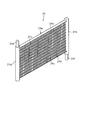
まず、冷蔵用冷却器24の詳細な構造について説明する。図2に示すように、冷媒の入口となるヘッダ24a、冷媒の出口となるヘッダ24b、これらヘッダ24aとヘッダ24bとの間を接続する偏平管24c、各偏平管24cの間に設けられている金属材料で波状に形成された吸熱用のフィン24d、入口側のヘッダ24aに設けられ、冷媒配管(図示省略)が接続される入口側接続部24e、および、出口側のヘッダ24bに設けられ、外部配管(図示省略)が接続される出口側接続部24fを備えている。このとき、偏平管24cが設けられている部位である本体部24gは、その外形が概ね薄い直方体状となっている。 Next, the operation of the above configuration will be described.
First, the detailed structure of therefrigeration cooler 24 will be described. As shown in FIG. 2, a header 24a serving as a refrigerant inlet, a header 24b serving as a refrigerant outlet, a flat tube 24c connecting the header 24a and the header 24b, and the flat tubes 24c are provided. An endothermic fin 24d formed in a wave shape with a metal material, provided on the inlet-side header 24a, provided on the inlet-side connecting portion 24e to which a refrigerant pipe (not shown) is connected, and provided on the outlet-side header 24b, The outlet side connection part 24f to which external piping (illustration omitted) is connected is provided. At this time, the main body 24g, which is a portion where the flat tube 24c is provided, has a rectangular parallelepiped shape.
まず、冷蔵用冷却器24の詳細な構造について説明する。図2に示すように、冷媒の入口となるヘッダ24a、冷媒の出口となるヘッダ24b、これらヘッダ24aとヘッダ24bとの間を接続する偏平管24c、各偏平管24cの間に設けられている金属材料で波状に形成された吸熱用のフィン24d、入口側のヘッダ24aに設けられ、冷媒配管(図示省略)が接続される入口側接続部24e、および、出口側のヘッダ24bに設けられ、外部配管(図示省略)が接続される出口側接続部24fを備えている。このとき、偏平管24cが設けられている部位である本体部24gは、その外形が概ね薄い直方体状となっている。 Next, the operation of the above configuration will be described.
First, the detailed structure of the
ヘッダ24aおよびヘッダ24bは、中空円筒状に形成されており、互いの中空部(図示省略)が各偏平管24cによってそれぞれ連通した状態となっている。より具体的には、偏平管24cは、図3に示すように、その外形が偏平状に形成されているとともに、その内部に冷媒が流れる複数の流路24hが形成されている。そして、各流路24hによって、ヘッダ24aおよびヘッダ24bの互いの中空部が連通している。
The header 24a and the header 24b are formed in a hollow cylindrical shape, and the respective hollow portions (not shown) are in communication with each flat tube 24c. More specifically, as shown in FIG. 3, the flat tube 24c has a flat outer shape and a plurality of flow paths 24h through which the refrigerant flows. And each hollow part of the header 24a and the header 24b is connected by each flow path 24h.
このように流路24hを複数設けることにより、従来のような系の大きい流路が1つ設けられているタイプのものに比べて、冷媒と偏平管24cとの接触面積が増大する。これにより、冷媒から偏平管24cに効率よく熱が伝わる。また、偏平管24cとフィン24dとが接触しているため、偏平管24cからフィン24dにも効率よく熱が伝わる。そして、フィン24dが波状に形成されていることから、空気との接触面積つまりは熱交換面積を一層大きくすることが可能となる。
By providing a plurality of the flow paths 24h in this way, the contact area between the refrigerant and the flat tube 24c is increased as compared with the conventional type in which one large flow path is provided. Thereby, heat is efficiently transferred from the refrigerant to the flat tube 24c. Further, since the flat tubes 24c and the fins 24d are in contact, heat is efficiently transferred from the flat tubes 24c to the fins 24d. Since the fins 24d are formed in a wave shape, the contact area with air, that is, the heat exchange area can be further increased.
このように、マルチフロー型の冷蔵用冷却器24は、空気との間で効率的な熱交換を行うことが可能となっている。例えば、冷蔵用冷却器24は、同体積であれば従来のフィンチューブ型のものに比べて2~3倍の吸熱効果が期待できる一方、従来と同様の吸熱効果を得られればよいのであれば薄型にできる等、体積を大きく削減することができる。これにより、本態様のように冷蔵庫1の背面側に冷蔵用冷却器24を配置する場合には、背面側のデッドスペースつまりは貯蔵室として利用できないスペースを削減することができる。
Thus, the multi-flow type refrigeration cooler 24 can efficiently exchange heat with air. For example, if the refrigeration cooler 24 has the same volume, it can be expected to have an endothermic effect that is two to three times that of a conventional fin tube type, while it is only required to obtain the same endothermic effect. The volume can be greatly reduced, such as being thin. Thereby, when arrange | positioning the refrigerator 24 for refrigeration on the back side of the refrigerator 1 like this aspect, the dead space on the back side, ie, the space which cannot be used as a storage room, can be reduced.
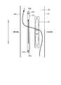
また、本態様の場合、冷蔵用冷却器24は、図4に示すように、入口側のヘッダ24aが下方に、出口側のヘッダ24bが上方となるように配置されている。換言すると、冷蔵用冷却器24は、偏平管24cが配置されている部位である本体部24gが冷蔵庫1の設置面に対して垂直となるように配置されているとともに、偏平管24cも設置面に対して垂直となるように配置されている。なお、ここでいう垂直とは、設置面に対して90度の状態に限らず、概ね垂直と見なせる状態、例えば若干斜めになった状態も含んでいる。
In the case of this embodiment, as shown in FIG. 4, the refrigerator 24 for refrigeration is arranged such that the inlet-side header 24a is on the lower side and the outlet-side header 24b is on the upper side. In other words, the refrigeration cooler 24 is disposed such that the main body 24g, which is a portion where the flat tube 24c is disposed, is perpendicular to the installation surface of the refrigerator 1, and the flat tube 24c is also disposed on the installation surface. It is arrange | positioned so that it may become perpendicular | vertical to. The term “perpendicular” here is not limited to a state of 90 degrees with respect to the installation surface, but includes a state that can be regarded as being substantially vertical, for example, a state that is slightly inclined.
冷蔵用冷却器24に流入する冷媒は、矢印Fにて示すように入口側接続部24eから冷蔵用冷却器24に液体状態で流入し、冷蔵用冷却器24内で蒸発して気体状態となった後、上方の出口側接続部24fから主に気体状態となって流出する。このとき、液体状態の冷媒は重力によって下方に流下することから、図4(B)に模式的に示すように冷媒の入口を下方に設置し、出口を上方に設置することにより、冷媒の移動をスムーズにすることができ、効率的な熱交換を行うことができる。なお、図4(B)は、図4(A)に示す冷蔵用冷却器24を図示左方側から視た状態を模式的に示している。
The refrigerant flowing into the refrigeration cooler 24 flows into the refrigeration cooler 24 in a liquid state from the inlet side connection portion 24e as indicated by an arrow F, and evaporates in the refrigeration cooler 24 to become a gas state. After that, the gas mainly flows out from the upper outlet side connection portion 24f. At this time, since the refrigerant in the liquid state flows down due to gravity, the refrigerant moves by installing the refrigerant at the lower side and installing the outlet at the upper side as schematically shown in FIG. Can be made smooth and efficient heat exchange can be performed. 4B schematically shows a state where the refrigeration cooler 24 shown in FIG. 4A is viewed from the left side in the figure.
さて、冷蔵用冷却器24は、冷凍サイクルが運転されると、温度が低下して霜が生じる。この霜は熱交換性能を低下させることから、霜を除去する除霜処理が例えば一定期間毎に行われている。この除霜処理では、付着した霜を溶かして除霜水として下方に排出している。そのため、本態様のように冷蔵用冷却器24の本体部24gを垂直に配置することにより、除霜水の流下を促すことができる。さらに、偏平管24cも垂直になるように配置していることにより、除霜水が偏平管24cを伝わりやすくなり、流下をさらに促すことができる。
Now, when the refrigerating cycle 24 is operated, the refrigeration cooler 24 decreases in temperature and generates frost. Since this frost reduces the heat exchange performance, a defrosting process for removing the frost is performed, for example, at regular intervals. In this defrosting process, the attached frost is melted and discharged downward as defrosted water. Therefore, the flow of the defrost water can be promoted by arranging the main body 24g of the refrigeration cooler 24 vertically as in this embodiment. Furthermore, by arranging the flat tube 24c so as to be vertical, the defrost water is easily transmitted through the flat tube 24c, and can further promote the flow down.
以上説明した冷蔵庫1によれば、次のような効果を得ることができる。
冷蔵庫1は、内部に冷媒が流れる流路24hが複数形成されている偏平管24cを有するマルチフロー型の冷蔵用冷却器24(エバポレータ)を用いて冷凍サイクルの熱交換を行う。 According to therefrigerator 1 demonstrated above, the following effects can be acquired.
Therefrigerator 1 performs heat exchange of the refrigeration cycle using a multi-flow type refrigeration cooler 24 (evaporator) having a flat tube 24c in which a plurality of flow paths 24h through which refrigerant flows are formed.
冷蔵庫1は、内部に冷媒が流れる流路24hが複数形成されている偏平管24cを有するマルチフロー型の冷蔵用冷却器24(エバポレータ)を用いて冷凍サイクルの熱交換を行う。 According to the
The
マルチフロー型の冷蔵用冷却器24は、上記したように熱交換性能が高く、同一性能であれば従来のフィンチューブ型のものに比べてその体積を大きく削減することができる。また、薄型化が可能となるため、配置場所の自由度も向上する。したがって、冷蔵用冷却器24の配置の自由度を高めることができ、有効な庫内体積つまりは貯蔵室に利用できる庫内スペースを稼ぐことができる。
The multi-flow type refrigeration cooler 24 has a high heat exchange performance as described above, and the volume can be greatly reduced as compared with the conventional fin tube type if the performance is the same. Further, since the thickness can be reduced, the degree of freedom of the arrangement location is also improved. Therefore, the freedom degree of arrangement | positioning of the cooler 24 for refrigeration can be raised, and the effective internal volume, ie, the internal space which can be utilized for a storage room, can be earned.
また、冷蔵用冷却器24の本体部24gを垂直に配置したことにより、除霜水の流下を促すことができる。この場合、偏平管24cも垂直になるように配置したことにより、除霜水が偏平管24cを伝わり易くなり、除霜水の流下をさらに促すことができる。
Moreover, the flow of the defrost water can be promoted by arranging the main body 24g of the refrigeration cooler 24 vertically. In this case, by arranging the flat tubes 24c so as to be vertical, the defrost water is easily transmitted through the flat tubes 24c, and the flow of the defrost water can be further promoted.
また、本態様のように冷蔵用冷却器24と冷凍用冷却器25の2つのエバポレータを有している場合には、冷蔵用冷却器24をその動作サイクル毎に毎サイクル除霜することができる。冷蔵用冷却器24は、冷媒がながれていれば冷却される一方、冷蔵室3の庫内温度が0℃以上であることから、冷媒が流れていなければ冷蔵用送風ファン35を回し続けることによりエバを温めて除霜することができる。
Moreover, when it has two evaporators, the refrigeration cooler 24 and the refrigeration cooler 25 as in this embodiment, the refrigeration cooler 24 can be defrosted every cycle for each operation cycle. . The refrigerating cooler 24 is cooled if the refrigerant is flowing, while the internal temperature of the refrigerating chamber 3 is 0 ° C. or higher. Therefore, if the refrigerant is not flowing, the refrigerating fan 35 is kept running. Eva can be warmed and defrosted.
このとき、マルチフロー型の冷蔵用冷却器24は熱容量が小さくなるため、従来のフィンチューブ型のものに比べて除霜時間が短くなり、効率の良い運転ができ、省電力化を図ることができる。
At this time, since the heat capacity of the multi-flow type refrigeration cooler 24 becomes smaller, the defrosting time is shorter than that of the conventional fin tube type, and an efficient operation can be achieved, thereby saving power. it can.
また、入口側接続部24eおよび出口側接続部24fを本体部24gと概ね平行に設けているので、冷蔵用冷却器24の前後方向への長さ(厚み)を薄くすることができ、貯蔵室を大きくすることができる。
Further, since the inlet side connecting portion 24e and the outlet side connecting portion 24f are provided substantially in parallel with the main body portion 24g, the length (thickness) in the front-rear direction of the refrigeration cooler 24 can be reduced, and the storage chamber Can be increased.
また、冷凍用冷却器25についても、冷蔵用冷却器24と同様の効果を得ることができる。
<第2態様>
以下、第2態様について、図5から図10を参照しながら説明する。第2態様では、冷蔵用冷却器24の配置態様および構造の他の例について説明する。 Further, the same effect as that of therefrigeration cooler 24 can be obtained for the refrigeration cooler 25.
<Second aspect>
Hereinafter, the second mode will be described with reference to FIGS. In the second aspect, another example of the arrangement and structure of therefrigeration cooler 24 will be described.
<第2態様>
以下、第2態様について、図5から図10を参照しながら説明する。第2態様では、冷蔵用冷却器24の配置態様および構造の他の例について説明する。 Further, the same effect as that of the
<Second aspect>
Hereinafter, the second mode will be described with reference to FIGS. In the second aspect, another example of the arrangement and structure of the
上記したように、冷蔵用冷却器24の下方側は、除霜水が流下するため、その範囲(流下領域(Rx。図7参照)内に冷蔵用送風ファン35を配置すると、除霜処理が行われた際に冷蔵用送風ファン35に除霜水がかかるおそれがある。
As described above, since the defrost water flows down on the lower side of the refrigeration cooler 24, if the refrigeration blower fan 35 is disposed in the range (flow area (Rx, see FIG. 7)), the defrost treatment is performed. When it is performed, there is a possibility that the defrost water is applied to the refrigeration blower fan 35.
そのため、例えば図5に示すように冷蔵用冷却器室36内に配置する場合には、冷蔵用冷却器24に送風するためのファン60を、冷蔵用冷却器24と概ね平行となる位置に配置することが考えられる。なお、ファン60は冷蔵用送風ファン35であってもよい。
Therefore, for example, as shown in FIG. 5, when arranged in the refrigeration cooler chamber 36, the fan 60 for sending air to the refrigeration cooler 24 is arranged at a position substantially parallel to the refrigeration cooler 24. It is possible to do. The fan 60 may be the refrigeration blower fan 35.
これにより、重力によって流下する除霜水がファン60にかかることを防止できる。なお、マルチフロー型の冷蔵用冷却器24であれば、上記したように薄型にできるため、冷蔵用冷却器室36内にファン60と併設することも可能である。
Thereby, it is possible to prevent the defrost water flowing down due to gravity from being applied to the fan 60. Note that the multi-flow type refrigeration cooler 24 can be thinned as described above, and therefore can be provided with the fan 60 in the refrigeration cooler chamber 36.
この場合、冷蔵用冷却器24の下方側には貯水容器56(図1参照)が設けられているため、この貯水容器56によって冷蔵用冷却器24の下方側の空間は、庫内側が一部塞がれた状態となっている。この状態でファン60を回転させた場合には、空気の流れは、矢印Bにて示すようにまず下方側からファン60に吸い込まれた後、冷蔵用冷却器24を通過して上方に抜けていく。
In this case, since a water storage container 56 (see FIG. 1) is provided on the lower side of the refrigeration cooler 24, the space on the lower side of the refrigeration cooler 24 by the water storage container 56 is partially on the inside of the refrigerator. It is in a blocked state. When the fan 60 is rotated in this state, the air flow is first sucked into the fan 60 from the lower side as indicated by an arrow B, and then passes upward through the refrigeration cooler 24. Go.
つまり、このファン60は、冷蔵用冷却器24に対して風の流れの上流側つまりは風上側に配置されている。これにより、冷蔵用冷却器24に生じた霜が飛び散ったり蒸発したりした場合であっても、水分がファン60にかかることを防止できる。
That is, the fan 60 is arranged on the upstream side of the wind flow, that is, on the windward side with respect to the refrigeration cooler 24. Thereby, even if the frost generated in the refrigeration cooler 24 is scattered or evaporated, it is possible to prevent moisture from being applied to the fan 60.
あるいは、図6に示すように冷気ダクト34内に配置する場合には、冷蔵用冷却器24の上方側にファン60を配置することができる。これにより、除霜水がファン60にかかることを防止できる。この場合、下方側から吸い上げられた空気は、矢印Bにて示すように冷蔵用冷却器24を通った後に上方に抜けていくものの、飛び散った水滴は重力によって下方に移動すると考えられるため、ファン60にかかるおそれは低減される。
Alternatively, when arranged in the cold air duct 34 as shown in FIG. 6, the fan 60 can be arranged above the refrigeration cooler 24. Thereby, it can prevent that defrost water applies to the fan 60. FIG. In this case, although the air sucked from the lower side passes through the refrigeration cooler 24 as indicated by an arrow B, it is considered that the scattered water droplets move downward due to gravity. The risk of 60 is reduced.
あるいは、図7に示すように、冷蔵用冷却器24よりも下方であっても、除霜水の流下領域(Rx)つまりは概ね冷蔵用冷却器24の真下の範囲から外れた位置であれば除霜水がファン60にかかることを防止できると考えられる。このとき、ファン60を、冷蔵用冷却器24に対して、冷蔵用冷却器24を通過する際の風向きとは逆側に配置するとよい。
Alternatively, as shown in FIG. 7, even if it is below the refrigeration cooler 24, the defrost water flow area (Rx), that is, a position that is substantially out of the range immediately below the refrigeration cooler 24. It is considered that defrost water can be prevented from being applied to the fan 60. At this time, the fan 60 may be disposed on the side opposite to the wind direction when passing through the refrigeration cooler 24 with respect to the refrigeration cooler 24.
図7の場合には冷蔵用冷却器24を通過する際の風向きが図示左向きであることから、ファン60を、冷蔵用冷却器24よりも図示右方側にするとよい。これにより、冷蔵用冷却器24の表面に付着した霜が風によって飛ばされたとしても、ファン60にかかるおそれを低減できる。
In the case of FIG. 7, the direction of the wind when passing through the refrigeration cooler 24 is leftward in the figure, and therefore, the fan 60 may be positioned on the right side of the refrigeration cooler 24 in the figure. Thereby, even if the frost adhering to the surface of the refrigeration cooler 24 is blown off by the wind, the risk of being applied to the fan 60 can be reduced.
このように、冷蔵用冷却器24は、除霜水の流下領域外であれば、任意の位置に配置することができる。そのため、例えば図6において、図示左右方向にスペースがあれば、ファン60を冷蔵用冷却器24の斜め上方等に配置することもできる。
As described above, the refrigeration cooler 24 can be disposed at an arbitrary position as long as it is outside the flow area of the defrost water. Therefore, for example, in FIG. 6, if there is a space in the horizontal direction in the figure, the fan 60 can be disposed obliquely above the refrigeration cooler 24.
また、冷蔵用冷却器24は、図8に示すように、冷蔵庫1の設置面に対して水平に配置できる。なお、ここで言う水平とは、概ね水平と見なせる状態、例えば若干斜めになった状態を含んでいる。
Moreover, the refrigerator 24 for refrigeration can be arrange | positioned horizontally with respect to the installation surface of the refrigerator 1, as shown in FIG. Here, the term “horizontal” includes a state that can be regarded as being almost horizontal, for example, a state that is slightly inclined.
このように概ね水平に配置することにより、高さ方向の必要スペースを削減することができる。また、天井に沿って配置したり、断熱仕切り部分に配置できたりするため、庫内容積を増大させることができる。
¡By arranging horizontally in this way, the required space in the height direction can be reduced. Moreover, since it can arrange | position along a ceiling or can arrange | position to a heat insulation partition part, the volume in a store | warehouse | chamber can be increased.
この場合、ファン60を冷蔵用冷却器24の上方に配置することで、除霜水がファン60にかかることを防止できる。また、概ね水平にすることにより、本体部24gを大きくして表面積を稼いだり、本体部24gを薄型化することで設置の自由度の向上や必要スペースの削減を図ったりすることができる。
In this case, it is possible to prevent the defrost water from being applied to the fan 60 by disposing the fan 60 above the refrigeration cooler 24. Further, by making the main body portion 24g large to increase the surface area, the main body portion 24g can be thinned to improve the degree of freedom of installation and reduce the required space.
また、図8では風向きを上向き、つまりは、冷蔵用冷却器24からファン60に向かう向きにしているが、冷蔵用冷却器24から剥離した霜は重力によって下方に移動するため、風向きが問題になることはない。なお、風向きを下向き、つまりは、ファン60から冷蔵用冷却器24に向かう向きにすることで、冷蔵用冷却器24から剥離した霜がファン60に付着することをさらに抑制できるようになる。
Further, in FIG. 8, the wind direction is upward, that is, the direction from the refrigeration cooler 24 toward the fan 60, but the frost peeled off from the refrigeration cooler 24 moves downward due to gravity, so the wind direction is a problem. Never become. In addition, it becomes possible to further suppress the frost peeled from the refrigeration cooler 24 from adhering to the fan 60 by making the wind direction downward, that is, the direction from the fan 60 toward the refrigeration cooler 24.
さて、ここまでは冷蔵用冷却器24としていわゆる並行式のものを説明したが、冷蔵用冷却器24は、図9に示すように蛇行式のものを採用できる。蛇行式の冷蔵用冷却器24は、1本の偏平管24cを折り返しながら冷媒の入口から出口までが接続された構成となっている。この偏平管24cには、冷媒の入口側にはヘッダ24aが設けられ、冷媒の出口側にはヘッダ24bが設けられている。また、折り返されている偏平管24cの間には、フィン24dが設けられている。
So far, the so-called parallel type has been described as the refrigeration cooler 24, but the refrigeration cooler 24 can adopt a meandering type as shown in FIG. The meandering refrigeration cooler 24 has a configuration in which the refrigerant is connected from the inlet to the outlet while folding one flat tube 24c. The flat tube 24c is provided with a header 24a on the refrigerant inlet side and a header 24b on the refrigerant outlet side. A fin 24d is provided between the folded flat tubes 24c.
このような蛇行式の冷蔵用冷却器24であっても、第1態様で示した並行式のものと同様に、熱交換性能が高く、同一性能であれば従来のフィンチューブ型のものに比べてその体積を大きく削減することができ、薄型化が可能となるため配置場所の自由度も向上することから、貯蔵室として利用可能な有効な庫内体積を稼ぐことができる。
Even in such a meandering refrigeration cooler 24, the heat exchange performance is high and the same performance as in the parallel type shown in the first aspect, compared to the conventional fin tube type. Thus, the volume can be greatly reduced and the thickness can be reduced, so that the degree of freedom of the arrangement location is also improved, so that an effective internal volume usable as a storage room can be earned.
ところで、冷蔵用冷却器24は、上記したように、液体状態の冷媒が流入し、気体状態で流出する。このとき、蒸発しきれなかった冷媒が、液体状態で流出するいわゆる液バックが生じる可能性がある。
By the way, as described above, the refrigeration cooler 24 flows in the liquid state refrigerant and flows out in the gaseous state. At this time, there may be a so-called liquid back in which the refrigerant that cannot be evaporated flows out in a liquid state.
そこで、図10(a)に模式的に示す並行式の冷蔵用冷却器24や図10(b)に模式的に示す蛇行式の冷蔵用冷却器24において、出口側のヘッダ24bの容積を、入口側のヘッダ24aの容積よりも大きく形成する。なお、図10は、ヘッダ24aとヘッダ24bの直径の違いにより、容積の違いを模式的に示している。
Therefore, in the parallel refrigeration cooler 24 schematically shown in FIG. 10 (a) and the meandering refrigeration cooler 24 schematically shown in FIG. 10 (b), the volume of the header 24b on the outlet side is It is formed larger than the volume of the header 24a on the inlet side. FIG. 10 schematically shows a difference in volume due to a difference in diameter between the header 24a and the header 24b.
これにより、出口側のヘッダ24bがアキュムレータのように機能し、冷蔵用冷却器24の後段側において冷媒が液体状態のまま循環するおそれを低減することができる。また、十分な容積を確保できれば、アキュムレータレス化を図ることもできる。
Thereby, the header 24b on the outlet side functions like an accumulator, and the possibility that the refrigerant circulates in the liquid state on the rear stage side of the refrigeration cooler 24 can be reduced. If a sufficient volume can be secured, accumulator-less operation can be achieved.
また、冷凍用冷却器25についても、冷蔵用冷却器24と同様の効果を得ることができる。
<第3態様>
以下、第3態様について、図11から図13を参照しながら説明する。第3態様では、冷蔵用冷却器24の設置場所の他の例について説明する。 Further, the same effect as that of therefrigeration cooler 24 can be obtained for the refrigeration cooler 25.
<Third aspect>
Hereinafter, the third aspect will be described with reference to FIGS. 11 to 13. In the third aspect, another example of the installation location of therefrigeration cooler 24 will be described.
<第3態様>
以下、第3態様について、図11から図13を参照しながら説明する。第3態様では、冷蔵用冷却器24の設置場所の他の例について説明する。 Further, the same effect as that of the
<Third aspect>
Hereinafter, the third aspect will be described with reference to FIGS. 11 to 13. In the third aspect, another example of the installation location of the
第1態様では冷蔵室3内のチルド室14の後方に冷蔵用冷却器24を配置した例を示したが、冷蔵用冷却器24は、他の場所にも配置することができる。
例えば、図11に示すように、冷蔵用冷却器24を、冷蔵庫1の内部であって天井側且つ背面側(以下、便宜的に上部背面側と称する)に配置することができる。冷蔵庫1の上部背面側は、冷蔵庫1の大きさにもよるものの、冷蔵室3に食材を出し入れする際に比較的手が届き難い場所である。また、マルチフロー型の冷蔵用冷却器24は上記したように小型化されているため、その必要スペースも小さくなっている。 Although the example which has arrange | positioned therefrigeration cooler 24 behind the chilled chamber 14 in the refrigerator compartment 3 in the 1st aspect was shown, the refrigerator 24 for refrigeration can also be arrange | positioned in another place.
For example, as shown in FIG. 11, therefrigeration cooler 24 can be disposed inside the refrigerator 1 on the ceiling side and the back side (hereinafter referred to as the upper back side for convenience). The upper back side of the refrigerator 1 is a place that is relatively difficult to reach when putting food into and out of the refrigerator compartment 3 depending on the size of the refrigerator 1. Further, since the multi-flow type refrigeration cooler 24 is downsized as described above, the required space is also reduced.
例えば、図11に示すように、冷蔵用冷却器24を、冷蔵庫1の内部であって天井側且つ背面側(以下、便宜的に上部背面側と称する)に配置することができる。冷蔵庫1の上部背面側は、冷蔵庫1の大きさにもよるものの、冷蔵室3に食材を出し入れする際に比較的手が届き難い場所である。また、マルチフロー型の冷蔵用冷却器24は上記したように小型化されているため、その必要スペースも小さくなっている。 Although the example which has arrange | positioned the
For example, as shown in FIG. 11, the
そこで、上部背面側に冷蔵用冷却器室36のスペースを確保し、そこに冷蔵用冷却器24を配置することにより、比較的手が届き難い場所を有効活用することができる。また、チルド室14の後方側には冷蔵用冷却器室36用のスペースが不要となることから、チルド室14を大きくすることができる。
Therefore, by securing a space for the refrigeration cooler chamber 36 on the upper back side and arranging the refrigeration cooler 24 there, it is possible to effectively utilize a place that is relatively difficult to reach. Further, since the space for the refrigeration cooler chamber 36 is not required on the rear side of the chilled chamber 14, the chilled chamber 14 can be enlarged.
この場合、図12に示すように、冷蔵用冷却器24と冷蔵用送風ファン35を併設(図5参照)して上部背面側に配置することにより、本態様では野菜室4の後方に空きスペースができることから、野菜室4も大型化することができる。
In this case, as shown in FIG. 12, the refrigeration cooler 24 and the refrigeration blower fan 35 are provided side by side (see FIG. 5) and arranged on the upper back side, so that an empty space is provided behind the vegetable compartment 4 in this embodiment. Therefore, the vegetable compartment 4 can also be enlarged.
また、図13に示すように、冷蔵用冷却器24と冷蔵用送風ファン35を併設(図5参照)してチルド室14の後方に配置した場合には、野菜室4を大型化することができる。
このように、冷蔵用冷却器24にマルチフロー型のものを採用することにより、冷蔵用冷却器24だけでなく冷蔵用送風ファン35の配置場所や配置態様の自由度も向上する。これにより、食材の出し入れがし辛い上部背面側を有効活用できる等、貯蔵室として利用可能な有効な庫内体積を稼ぐことができる。また、冷凍用冷却器25についても、冷蔵用冷却器24と同様の効果を得ることができる。 Moreover, as shown in FIG. 13, when therefrigeration cooler 24 and the refrigeration blower fan 35 are provided side by side (see FIG. 5) and arranged behind the chilled chamber 14, the vegetable compartment 4 may be enlarged. it can.
Thus, by adopting a multi-flow type as therefrigeration cooler 24, not only the refrigeration cooler 24 but also the refrigeration blower fan 35 can be arranged and the degree of freedom is improved. Thereby, the effective internal volume which can be used as a storage room can be earned, such as being able to effectively utilize the upper back side where it is difficult to put in and out food. Further, the same effect as that of the refrigeration cooler 24 can be obtained for the refrigeration cooler 25.
このように、冷蔵用冷却器24にマルチフロー型のものを採用することにより、冷蔵用冷却器24だけでなく冷蔵用送風ファン35の配置場所や配置態様の自由度も向上する。これにより、食材の出し入れがし辛い上部背面側を有効活用できる等、貯蔵室として利用可能な有効な庫内体積を稼ぐことができる。また、冷凍用冷却器25についても、冷蔵用冷却器24と同様の効果を得ることができる。 Moreover, as shown in FIG. 13, when the
Thus, by adopting a multi-flow type as the
<複数配置態様>
まず、複数配置態様の背景について説明する。従来では、異なる温度帯の貯蔵室を冷却する際、冷蔵室3や冷凍室7をそれぞれ別の冷却器で冷却していた。しかし、近年では、概ね同一温度帯となる冷蔵室3や野菜室4あるいはチルド室14、概ね同一温度帯となる製氷室5や小冷凍室6あるは冷凍室7等、同一温度帯の複数の貯蔵庫を備えるものが増えてきている。 <Multiple arrangement mode>
First, the background of the multiple arrangement mode will be described. Conventionally, when cooling storage rooms in different temperature zones, therefrigerator compartment 3 and the freezer compartment 7 are cooled by separate coolers. However, in recent years, a plurality of the same temperature range such as the refrigeration room 3, the vegetable room 4 or the chilled room 14, which are in the same temperature range, the ice making room 5, the small freezer room 6 or the freezer room 7 in the same temperature range, etc. An increasing number of stores are equipped.
まず、複数配置態様の背景について説明する。従来では、異なる温度帯の貯蔵室を冷却する際、冷蔵室3や冷凍室7をそれぞれ別の冷却器で冷却していた。しかし、近年では、概ね同一温度帯となる冷蔵室3や野菜室4あるいはチルド室14、概ね同一温度帯となる製氷室5や小冷凍室6あるは冷凍室7等、同一温度帯の複数の貯蔵庫を備えるものが増えてきている。 <Multiple arrangement mode>
First, the background of the multiple arrangement mode will be described. Conventionally, when cooling storage rooms in different temperature zones, the
このように同一温度帯の貯蔵室が複数ある場合、単一の冷却器による冷却では、冷気ダクトを引き回す必要があり、その分だけ貯蔵室として利用可能な庫内容積が低下してしまう。また、同一温度帯の貯蔵室に対して複数の冷却器を用いる構成とすると、従来のフィンチューブ型の冷却器では、冷却器がある程度の大きさを有することから、やはり庫内容積が低下してしまう。
When there are a plurality of storage chambers in the same temperature range as described above, the cooling with a single cooler requires the cold air duct to be routed, and the internal volume that can be used as the storage chamber decreases accordingly. In addition, when a plurality of coolers are used for a storage room in the same temperature range, the conventional finned-tube type cooler has a certain size, so that the internal volume is also reduced. End up.
そこで、複数配置態様では、同一温度帯の貯蔵室の冷却用に、内部に冷媒が流れる流路が複数形成された偏平管24c(図2等参照)を有するマルチフロー型のエバポレータを複数用いている。以下、マルチフロー型のエバポレータを複数設ける具体的な構成例について説明する。
Therefore, in the multiple arrangement mode, a plurality of multiflow evaporators having a flat tube 24c (see FIG. 2 and the like) in which a plurality of flow paths through which a refrigerant flows are formed are used for cooling the storage chamber in the same temperature range. Yes. A specific configuration example in which a plurality of multiflow evaporators are provided will be described below.
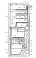
図14は、本態様の冷蔵庫100を模式的に示している。この冷蔵庫100には、最上段側に冷蔵室3が設けられ、その下方に製氷室5と小冷凍室6が左右に並べて設けられ、これらの下方に野菜室4が設けられ、その下方に冷凍室7が設けられている。ここで、冷蔵室3および野菜室4は、冷蔵温度帯の貯蔵室つまりは概ね同一温度帯の貯蔵室であり、製氷室5、小冷凍室6および冷凍室7は、冷凍温度帯の貯蔵室つまりは概ね同一温度帯の貯蔵室である。
FIG. 14 schematically shows the refrigerator 100 of this aspect. In the refrigerator 100, the refrigerator compartment 3 is provided on the uppermost side, the ice making chamber 5 and the small freezer compartment 6 are provided side by side on the lower side, the vegetable compartment 4 is provided below these, and the freezer is placed on the lower side. A chamber 7 is provided. Here, the refrigerator compartment 3 and the vegetable compartment 4 are storage compartments in a refrigerated temperature zone, that is, roughly the same temperature zone, and the ice making chamber 5, the small freezer compartment 6 and the freezer compartment 7 are storage compartments in a freezing temperature zone. In other words, it is a storage room of almost the same temperature range.
つまり、冷蔵庫100の場合、同一温度帯の冷蔵室3と野菜室4との間に、異なる温度帯の製氷室5および小冷凍室6が配置されている。そして、冷蔵庫100は、冷蔵室3を冷却するための第1R冷却器110、野菜室4を冷却するための第2R冷却器111、製氷室5および小冷凍室6を冷却するための第1F冷却器112、および、冷凍室7を冷却するための第2F冷却器113を備えている。また、各貯蔵室の間は、断熱仕切り101により区切られている。
That is, in the case of the refrigerator 100, the ice making room 5 and the small freezer room 6 in different temperature zones are arranged between the refrigerator compartment 3 and the vegetable compartment 4 in the same temperature zone. The refrigerator 100 includes a first R cooler 110 for cooling the refrigerator compartment 3, a second R cooler 111 for cooling the vegetable compartment 4, the first ice cooling for cooling the ice making chamber 5 and the small freezer compartment 6. And a second F cooler 113 for cooling the freezer compartment 7. Further, the storage rooms are partitioned by a heat insulating partition 101.
上記したように、マルチフロー型のエバポレータは、従来のフィンチューブ型のものに比べて同体積であれば2~3倍の吸熱効果が期待できる一方、従来と同等の吸熱効果を得られればよいのであれば、小型化且つ薄型化が可能となり、必要な設置スペースを大きく削減することができる。そのため、同一温度帯の貯蔵室に対して複数のマルチフロー型のエバポレータを用いることにより、庫内容積が大きく低下してしまうことを抑制することができる。すなわち、マルチフロー型の冷却器(エバポレータ)は、従来のフィンチューブ型の冷却器に比べると、薄型化および小型化を図ることができる。
As described above, the multi-flow type evaporator can be expected to have a heat absorption effect of 2 to 3 times as long as the volume is the same as that of the conventional fin tube type, while it is only required to obtain the same endothermic effect as the conventional one. If it is, it will become possible to reduce in size and thickness, and a required installation space can be reduced significantly. Therefore, by using a plurality of multi-flow type evaporators for the storage chamber in the same temperature range, it is possible to suppress a large decrease in the internal volume. That is, the multiflow type cooler (evaporator) can be reduced in thickness and size as compared with the conventional fin tube type cooler.
また、例えば冷蔵室3と野菜室4との間等を冷気ダクトで接続しなくてもよいことから、冷気ダクトを引き回す必要がなく、庫内容積が低下することを防止できる。
また、第1R冷却器110、第2R冷却器111、第1F冷却器112および第2F冷却器113には、それぞれ送風ファン120~122が設けられている。これにより各冷却器における熱交換が促進することができ、吸熱効果を向上させることができる。 Moreover, since it is not necessary to connect between therefrigerator compartment 3 and the vegetable compartment 4 etc. with a cold air duct, for example, it is not necessary to route a cold air duct and it can prevent that a warehouse volume falls.
Further, thefirst R cooler 110, the second R cooler 111, the first F cooler 112, and the second F cooler 113 are provided with blower fans 120 to 122, respectively. Thereby, the heat exchange in each cooler can be promoted, and the endothermic effect can be improved.
また、第1R冷却器110、第2R冷却器111、第1F冷却器112および第2F冷却器113には、それぞれ送風ファン120~122が設けられている。これにより各冷却器における熱交換が促進することができ、吸熱効果を向上させることができる。 Moreover, since it is not necessary to connect between the
Further, the
ここで、第1R冷却器110、第2R冷却器111、第1F冷却器112および第2F冷却器113の接続態様について説明する。
まず、図15は、冷却器を直列に接続する際の接続態様を模式的に示している。この場合、第1R冷却器110および第2R冷却器111は、例えば三方弁で構成される切換弁104により切り替えられる冷蔵温度帯用の冷媒が流れる経路において、第1R冷却器110が上流側に接続され、その下流側に第2R冷却器111が接続されている。 Here, a connection mode of thefirst R cooler 110, the second R cooler 111, the first F cooler 112, and the second F cooler 113 will be described.
First, FIG. 15 schematically shows a connection mode when the coolers are connected in series. In this case, thefirst R cooler 110 and the second R cooler 111 are connected to the upstream side in the path through which the refrigerant for the refrigeration temperature zone switched by the switching valve 104 configured by, for example, a three-way valve flows. The second R cooler 111 is connected to the downstream side.
まず、図15は、冷却器を直列に接続する際の接続態様を模式的に示している。この場合、第1R冷却器110および第2R冷却器111は、例えば三方弁で構成される切換弁104により切り替えられる冷蔵温度帯用の冷媒が流れる経路において、第1R冷却器110が上流側に接続され、その下流側に第2R冷却器111が接続されている。 Here, a connection mode of the
First, FIG. 15 schematically shows a connection mode when the coolers are connected in series. In this case, the
同様に、第1F冷却器112および第2F冷却器113は、切換弁104により切り替えられる冷凍温度帯用の冷媒が流れる経路において、第1F冷却器112が上流側に接続され、その下流側に第2F冷却器113が接続されている。これらの冷却器は、圧縮機27や凝縮器103とともに、冷凍サイクル105を構成している。
Similarly, the first F cooler 112 and the second F cooler 113 are connected to the upstream side of the first F cooler 112 in the path through which the refrigerant for the refrigeration temperature zone switched by the switching valve 104 flows. A 2F cooler 113 is connected. These coolers constitute a refrigeration cycle 105 together with the compressor 27 and the condenser 103.
このように、冷却器を直列に接続することにより、各冷却器への冷媒の流れを個別に切り替える構成が不要となることから、コストの増加を抑制することができる。
また、本態様のように同一温度帯の貯蔵室が複数且つ隣り合わない位置に配置されている場合には、つまりは、同一温度帯の貯蔵室の間に異なる温度帯の貯蔵室が設けられている場合には、複数の冷却器によりそれぞれ別の貯蔵室を冷却することにより、冷却ダクトを大きく引き回す必要がなくなり、庫内容積の低下を大きく抑制することができる。 Thus, by connecting the coolers in series, a configuration for individually switching the flow of the refrigerant to each cooler becomes unnecessary, so that an increase in cost can be suppressed.
In addition, when the storage chambers of the same temperature range are arranged in a plurality of positions that are not adjacent to each other as in this aspect, that is, storage chambers of different temperature zones are provided between the storage chambers of the same temperature range. In this case, by cooling the separate storage chambers with a plurality of coolers, it is not necessary to draw a large cooling duct, and a reduction in the internal volume can be greatly suppressed.
一方、図16は、冷却器を並列に接続する際の接続態様を模式的に示している。この場合、例えば五方弁や複数の三方弁で構成される切換弁104によって、冷媒が流れる経路は、第1R冷却器110、第2R冷却器111、第1F冷却器112および第2F冷却器113に対して個別に切り替えられる。
On the other hand, FIG. 16 schematically shows a connection mode when the coolers are connected in parallel. In this case, for example, the path through which the refrigerant flows by the switching valve 104 including a five-way valve or a plurality of three-way valves is the first R cooler 110, the second R cooler 111, the first F cooler 112, and the second F cooler 113. Can be switched individually.
このように、冷却器を並列に接続することにより、各冷却器への冷媒の流れを個別に切り替えることが可能となり、冷却器毎に適切な蒸発温度で運転させることが可能となり、省エネルギー化を促進することができる。
In this way, by connecting the coolers in parallel, the refrigerant flow to each cooler can be individually switched, and each cooler can be operated at an appropriate evaporation temperature, saving energy. Can be promoted.
また、各冷却器は、それぞれ別の貯蔵室を冷却する。従来のように同一温度帯の貯蔵室を単一の冷却器で冷却する場合、例えば冷蔵室3を冷却する際には、野菜室4も必然的に冷却されていた。そのため、野菜室4が開閉されていなくても野菜室4も冷却されてしまう可能性があったが、個別の冷却器によりそれぞれ別の貯蔵室を冷却することにより、例えば冷蔵室3の扉が開閉されて冷蔵室3の温度が上昇した場合であっても、冷蔵室3だけを冷却することができる。すなわち、各貯蔵室を、それぞれ個別に適切な温度に維持することができる。また、コンパクトな冷却器を用いていることから、庫内容積への影響を小さく抑えることができる。
Also, each cooler cools a separate storage room. When the storage room of the same temperature zone is cooled with a single cooler as in the prior art, for example, when the refrigerator compartment 3 is cooled, the vegetable compartment 4 is inevitably cooled. Therefore, although the vegetable compartment 4 may be cooled even if the vegetable compartment 4 is not opened and closed, for example, the doors of the refrigerator compartment 3 can be cooled by cooling separate storage compartments with individual coolers. Even when the temperature of the refrigerator compartment 3 is increased by opening and closing, only the refrigerator compartment 3 can be cooled. That is, each storage room can be individually maintained at an appropriate temperature. Moreover, since the compact cooler is used, the influence on the internal volume can be kept small.
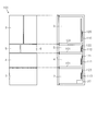
また、図14に示した冷蔵庫100の貯蔵室の構成は一例であり、例えば図14において野菜室4と冷凍室7との順序を入れ替えて、最上段に冷蔵室3、最下段に野菜室4を配置した構成とすることもできる。その場合、離間して配置されている冷蔵室3と野菜室4とをそれぞれ別の冷却器で冷却し、隣り合って配置されている製氷室5、小冷凍室6、冷凍室7は1つの冷却器で冷却する構成とすることもできる。
Moreover, the structure of the storage room of the refrigerator 100 shown in FIG. 14 is an example. For example, in FIG. 14, the order of the vegetable room 4 and the freezing room 7 is changed, and the refrigerator room 3 is arranged at the top and the vegetable room 4 is arranged at the bottom. It can also be set as the structure which arranged. In that case, the refrigerator compartment 3 and the vegetable compartment 4 which are arranged apart from each other are cooled by separate coolers, and the ice making compartment 5, the small freezer compartment 6 and the freezer compartment 7 which are arranged adjacent to each other are one. It can also be set as the structure cooled with a cooler.
つまり、同一温度帯の貯蔵室として冷蔵温度帯の冷蔵室3、野菜室4またはチルド室14のいずれか、あるいは、それらの組み合わせであっても、冷蔵温度帯の貯蔵室の冷却を効率的に行うことができる。同様に、同一温度帯の貯蔵室として冷凍温度帯の製氷室5、小冷凍室6または冷凍室7のいずれか、あるいは、それらの組み合わせであっても、冷凍温度帯の貯蔵室の冷却を効率的に行うことができる。また、製氷室5や小冷凍室6を備えていない場合であっても、本態様で例示した構成を適用することができる。
That is, even if the storage room in the same temperature range is any of the refrigeration room 3 in the refrigeration temperature range, the vegetable room 4 or the chilled room 14, or a combination thereof, the storage room in the refrigeration temperature range can be efficiently cooled. It can be carried out. Similarly, it is possible to efficiently cool the storage room in the freezing temperature zone even if any of the ice making room 5 in the freezing temperature zone, the small freezing room 6 or the freezing room 7 or a combination thereof as the storage room in the same temperature zone. Can be done automatically. Moreover, even if it is a case where the ice making room 5 and the small freezer compartment 6 are not provided, the structure illustrated by this aspect is applicable.
また、図17に示すように、冷蔵室3内にチルド室14が設けられている場合には、チルド室14に第3R冷却器114を設け、冷蔵室3、野菜室4およびチルド室14をそれぞれ個別に冷却する構成とすることができる。この場合、例えばチルド室14の温度をユーザが設定可能とすること等によって、より適切な温度範囲での食品等の保存が可能となり、利便性を向上させることができる。すなわち、同一温度帯の貯蔵室を3以上設ける構成とすることができる。
As shown in FIG. 17, when the chilled chamber 14 is provided in the refrigerated chamber 3, a third R cooler 114 is provided in the chilled chamber 14, and the refrigerated chamber 3, the vegetable chamber 4, and the chilled chamber 14 are provided. Each can be individually cooled. In this case, for example, by enabling the user to set the temperature of the chilled chamber 14, food can be stored in a more appropriate temperature range, and convenience can be improved. That is, it can be set as the structure which provides 3 or more of storage rooms of the same temperature range.
(その他の実施形態)
実施形態ではヘッダ24a、24bを有するマルチフロー型のエバポレータを例示したが、ヘッダ24a等を介さず、偏平管24cに直接的に外部配管を接続する構成にすることができる。 (Other embodiments)
In the embodiment, the multi-flow type evaporator having the headers 24a and 24b has been exemplified. However, the external pipe can be directly connected to the flat tube 24c without using the header 24a or the like.
実施形態ではヘッダ24a、24bを有するマルチフロー型のエバポレータを例示したが、ヘッダ24a等を介さず、偏平管24cに直接的に外部配管を接続する構成にすることができる。 (Other embodiments)
In the embodiment, the multi-flow type evaporator having the
入口側接続部24eおよび出口側接続部24fが延びる向きは、実施形態で例示した向きに限らない。例えば、第1態様や図8に示したような冷蔵用冷却器24の配置の場合には、入口側接続部24eおよび出口側接続部24fを上下方向つまりはファン60の厚み方向に延びる向きとすることができる。これにより、入口側接続部24eおよび出口側接続部24fの長さの範囲内にファン60を配置することにより省スペース化を図ることができる。
The direction in which the inlet side connection part 24e and the outlet side connection part 24f extend is not limited to the direction illustrated in the embodiment. For example, in the case of the arrangement of the refrigeration cooler 24 as shown in the first mode or FIG. 8, the inlet side connecting portion 24e and the outlet side connecting portion 24f are arranged in the vertical direction, that is, in the direction extending in the thickness direction of the fan 60. can do. Thereby, space saving can be achieved by arranging the fan 60 within the range of the length of the inlet side connection part 24e and the outlet side connection part 24f.
各実施形態は、例として提示したものであり、発明の範囲を限定することは意図していない。これら新規な実施形態は、その他の様々な形態で実施されることが可能であり、発明の要旨を逸脱しない範囲で、種々の省略、置き換え、変更を行うことができる。本態様およびその変形は、発明の範囲および要旨に含まれるとともに、特許請求の範囲に記載された発明とその均等の範囲に含まれる。
Each embodiment is presented as an example, and is not intended to limit the scope of the invention. These novel embodiments can be implemented in various other forms, and various omissions, replacements, and changes can be made without departing from the scope of the invention. This aspect and its modifications are included in the scope and gist of the invention, and are included in the invention described in the claims and the equivalents thereof.
Claims (8)
- 同一温度帯の貯蔵室の冷却用に、内部に冷媒が流れる流路が複数形成された偏平管を有するマルチフロー型のエバポレータを複数用いることを特徴とする冷蔵庫。 Refrigerator characterized by using a plurality of multi-flow type evaporators having a flat tube in which a plurality of flow paths through which a refrigerant flows are formed for cooling a storage room in the same temperature range.
- 前記エバポレータに送風ファンを設けたことを特徴とする請求項1記載の冷蔵庫。 The refrigerator according to claim 1, wherein a blower fan is provided in the evaporator.
- 複数の前記エバポレータは、冷媒の流路に並列に接続されていることを特徴とする請求項1または2記載の冷蔵庫。 The refrigerator according to claim 1 or 2, wherein the plurality of evaporators are connected in parallel to a refrigerant flow path.
- 複数の前記エバポレータは、冷媒の流路に直列に接続されていることを特徴とする請求項1または2記載の冷蔵庫。 The refrigerator according to claim 1 or 2, wherein the plurality of evaporators are connected in series to a refrigerant flow path.
- 複数の前記エバポレータは、それぞれ別の貯蔵室を冷却することを特徴とする請求項1から4のいずれか一項記載の冷蔵庫。 The refrigerator according to any one of claims 1 to 4, wherein the plurality of evaporators cool different storage chambers.
- 同一温度帯の前記貯蔵室は、複数設けられており、当該冷蔵庫において隣り合わない位置に配置されていることを特徴とする請求項5記載の冷蔵庫。 6. The refrigerator according to claim 5, wherein a plurality of the storage chambers in the same temperature zone are provided and are arranged at positions not adjacent to each other in the refrigerator.
- 前記貯蔵室は、冷蔵温度帯の冷蔵室、野菜室またはチルド室のいずれか、あるいは、それらの組み合わせであることを特徴とする請求項1から6のいずれか一項記載の冷蔵庫。 The refrigerator according to any one of claims 1 to 6, wherein the storage room is any one of a refrigeration room in a refrigeration temperature zone, a vegetable room, a chilled room, or a combination thereof.
- 前記貯蔵室は、冷凍温度帯の冷凍室または製氷室のいずれか、あるいは、それらの組み合わせであることを特徴とする請求項1から7のいずれか一項記載の冷蔵庫。 The refrigerator according to any one of claims 1 to 7, wherein the storage room is either a freezing room or an ice making room in a freezing temperature zone, or a combination thereof.
Priority Applications (1)
| Application Number | Priority Date | Filing Date | Title |
|---|---|---|---|
| CN201880008804.2A CN110226074A (en) | 2017-03-03 | 2018-01-22 | Refrigerator |
Applications Claiming Priority (2)
| Application Number | Priority Date | Filing Date | Title |
|---|---|---|---|
| JP2017-040421 | 2017-03-03 | ||
| JP2017040421A JP6955348B2 (en) | 2017-03-03 | 2017-03-03 | refrigerator |
Publications (1)
| Publication Number | Publication Date |
|---|---|
| WO2018159151A1 true WO2018159151A1 (en) | 2018-09-07 |
Family
ID=63370403
Family Applications (1)
| Application Number | Title | Priority Date | Filing Date |
|---|---|---|---|
| PCT/JP2018/001785 WO2018159151A1 (en) | 2017-03-03 | 2018-01-22 | Refrigerator |
Country Status (4)
| Country | Link |
|---|---|
| JP (1) | JP6955348B2 (en) |
| CN (1) | CN110226074A (en) |
| TW (1) | TWI658245B (en) |
| WO (1) | WO2018159151A1 (en) |
Citations (9)
| Publication number | Priority date | Publication date | Assignee | Title |
|---|---|---|---|---|
| JPS5245864U (en) * | 1975-09-27 | 1977-03-31 | ||
| JP2003194448A (en) * | 2001-12-26 | 2003-07-09 | Mitsubishi Electric Corp | Refrigerator |
| JP2003314945A (en) * | 2002-04-18 | 2003-11-06 | Matsushita Refrig Co Ltd | Refrigerator |
| JP2004028354A (en) * | 2002-06-21 | 2004-01-29 | Hitachi Home & Life Solutions Inc | Refrigerator |
| JP2005114345A (en) * | 2003-10-10 | 2005-04-28 | Hussmann Corp | Evaporator for refrigerated merchandiser |
| JP2007333299A (en) * | 2006-06-14 | 2007-12-27 | Toshiba Corp | Refrigerator |
| JP2008020159A (en) * | 2006-07-14 | 2008-01-31 | Toshiba Corp | Refrigerator |
| KR20110085603A (en) * | 2010-01-21 | 2011-07-27 | 엘지전자 주식회사 | Refrigerator |
| US20130098081A1 (en) * | 2011-10-24 | 2013-04-25 | Whirlpool Corporation | Higher efficiency appliance employing thermal load shifting in refrigerators having horizontal mullion |
Family Cites Families (4)
| Publication number | Priority date | Publication date | Assignee | Title |
|---|---|---|---|---|
| KR20070054531A (en) * | 2005-11-23 | 2007-05-29 | 엘지전자 주식회사 | Refrigerator |
| TWM468663U (en) * | 2013-06-07 | 2013-12-21 | Man Zai Ind Co Ltd | Micro-channel heat exchanger |
| JP6261432B2 (en) * | 2014-04-03 | 2018-01-17 | 三菱電機株式会社 | refrigerator |
| CN205245622U (en) * | 2015-11-30 | 2016-05-18 | 河南新飞电器有限公司 | Little micro -channel condenser in multithread way |
-
2017
- 2017-03-03 JP JP2017040421A patent/JP6955348B2/en active Active
-
2018
- 2018-01-08 TW TW107100587A patent/TWI658245B/en not_active IP Right Cessation
- 2018-01-22 CN CN201880008804.2A patent/CN110226074A/en active Pending
- 2018-01-22 WO PCT/JP2018/001785 patent/WO2018159151A1/en active Application Filing
Patent Citations (9)
| Publication number | Priority date | Publication date | Assignee | Title |
|---|---|---|---|---|
| JPS5245864U (en) * | 1975-09-27 | 1977-03-31 | ||
| JP2003194448A (en) * | 2001-12-26 | 2003-07-09 | Mitsubishi Electric Corp | Refrigerator |
| JP2003314945A (en) * | 2002-04-18 | 2003-11-06 | Matsushita Refrig Co Ltd | Refrigerator |
| JP2004028354A (en) * | 2002-06-21 | 2004-01-29 | Hitachi Home & Life Solutions Inc | Refrigerator |
| JP2005114345A (en) * | 2003-10-10 | 2005-04-28 | Hussmann Corp | Evaporator for refrigerated merchandiser |
| JP2007333299A (en) * | 2006-06-14 | 2007-12-27 | Toshiba Corp | Refrigerator |
| JP2008020159A (en) * | 2006-07-14 | 2008-01-31 | Toshiba Corp | Refrigerator |
| KR20110085603A (en) * | 2010-01-21 | 2011-07-27 | 엘지전자 주식회사 | Refrigerator |
| US20130098081A1 (en) * | 2011-10-24 | 2013-04-25 | Whirlpool Corporation | Higher efficiency appliance employing thermal load shifting in refrigerators having horizontal mullion |
Also Published As
| Publication number | Publication date |
|---|---|
| JP6955348B2 (en) | 2021-10-27 |
| CN110226074A (en) | 2019-09-10 |
| JP2018146158A (en) | 2018-09-20 |
| TW201833497A (en) | 2018-09-16 |
| TWI658245B (en) | 2019-05-01 |
Similar Documents
| Publication | Publication Date | Title |
|---|---|---|
| US8261573B2 (en) | Refrigerator | |
| JP5872143B2 (en) | refrigerator | |
| JP2009133504A (en) | Refrigerator freezer | |
| JP2008249292A (en) | Refrigerator | |
| US7950247B2 (en) | Refrigerator related technology | |
| JP5450462B2 (en) | refrigerator | |
| JP7369434B2 (en) | refrigerator | |
| JP2012127629A (en) | Cooling storage cabinet | |
| JP2021076296A (en) | refrigerator | |
| JP2015102320A (en) | Refrigerator | |
| JP7032055B2 (en) | refrigerator | |
| JP2014048031A (en) | Refrigerator | |
| JP2014077615A (en) | Refrigerator | |
| JP2008111640A (en) | Refrigerator | |
| WO2018159151A1 (en) | Refrigerator | |
| JP2005345061A (en) | Refrigerator | |
| JP5916174B2 (en) | refrigerator | |
| JP6940424B2 (en) | refrigerator | |
| JP2021101136A (en) | refrigerator | |
| JP2005016903A (en) | Refrigerator | |
| JP5990731B2 (en) | refrigerator | |
| JP6139286B2 (en) | refrigerator | |
| JP2013096607A (en) | Refrigerator | |
| JP4203662B2 (en) | refrigerator | |
| WO2010092625A1 (en) | Refrigerator |
Legal Events
| Date | Code | Title | Description |
|---|---|---|---|
| 121 | Ep: the epo has been informed by wipo that ep was designated in this application |
Ref document number: 18760538 Country of ref document: EP Kind code of ref document: A1 |
|
| NENP | Non-entry into the national phase |
Ref country code: DE |
|
| 122 | Ep: pct application non-entry in european phase |
Ref document number: 18760538 Country of ref document: EP Kind code of ref document: A1 |