WO2018135518A1 - 黒色めっき鋼板の製造方法およびその製造装置 - Google Patents
黒色めっき鋼板の製造方法およびその製造装置 Download PDFInfo
- Publication number
- WO2018135518A1 WO2018135518A1 PCT/JP2018/001153 JP2018001153W WO2018135518A1 WO 2018135518 A1 WO2018135518 A1 WO 2018135518A1 JP 2018001153 W JP2018001153 W JP 2018001153W WO 2018135518 A1 WO2018135518 A1 WO 2018135518A1
- Authority
- WO
- WIPO (PCT)
- Prior art keywords
- sealed container
- water vapor
- plated steel
- steel sheet
- pressure
- Prior art date
Links
- 229910000831 Steel Inorganic materials 0.000 title claims abstract description 194
- 239000010959 steel Substances 0.000 title claims abstract description 194
- 238000004519 manufacturing process Methods 0.000 title claims abstract description 30
- 238000000034 method Methods 0.000 title abstract description 37
- XLYOFNOQVPJJNP-UHFFFAOYSA-N water Chemical compound O XLYOFNOQVPJJNP-UHFFFAOYSA-N 0.000 claims abstract description 183
- 238000007747 plating Methods 0.000 claims abstract description 67
- 229910052749 magnesium Inorganic materials 0.000 claims description 24
- 229910052782 aluminium Inorganic materials 0.000 claims description 23
- 239000007789 gas Substances 0.000 description 125
- 239000010410 layer Substances 0.000 description 59
- 230000007246 mechanism Effects 0.000 description 52
- 238000010438 heat treatment Methods 0.000 description 30
- UFHFLCQGNIYNRP-UHFFFAOYSA-N Hydrogen Chemical compound [H][H] UFHFLCQGNIYNRP-UHFFFAOYSA-N 0.000 description 23
- 230000008569 process Effects 0.000 description 20
- 238000006243 chemical reaction Methods 0.000 description 18
- 125000006850 spacer group Chemical group 0.000 description 13
- 238000009833 condensation Methods 0.000 description 11
- 230000005494 condensation Effects 0.000 description 11
- 238000012545 processing Methods 0.000 description 11
- 238000003756 stirring Methods 0.000 description 11
- QVGXLLKOCUKJST-UHFFFAOYSA-N atomic oxygen Chemical compound [O] QVGXLLKOCUKJST-UHFFFAOYSA-N 0.000 description 7
- 230000005496 eutectics Effects 0.000 description 7
- 229910052751 metal Inorganic materials 0.000 description 7
- 239000002184 metal Substances 0.000 description 7
- 239000001301 oxygen Substances 0.000 description 7
- 229910052760 oxygen Inorganic materials 0.000 description 7
- 238000001816 cooling Methods 0.000 description 6
- XLYOFNOQVPJJNP-UHFFFAOYSA-M hydroxide Chemical compound [OH-] XLYOFNOQVPJJNP-UHFFFAOYSA-M 0.000 description 5
- 239000000463 material Substances 0.000 description 5
- 239000000203 mixture Substances 0.000 description 5
- IJGRMHOSHXDMSA-UHFFFAOYSA-N Atomic nitrogen Chemical compound N#N IJGRMHOSHXDMSA-UHFFFAOYSA-N 0.000 description 4
- 230000007547 defect Effects 0.000 description 4
- 230000002950 deficient Effects 0.000 description 4
- 238000007599 discharging Methods 0.000 description 4
- 229910000765 intermetallic Inorganic materials 0.000 description 4
- 238000009529 body temperature measurement Methods 0.000 description 3
- 239000013078 crystal Substances 0.000 description 3
- 238000010586 diagram Methods 0.000 description 3
- 239000001257 hydrogen Substances 0.000 description 3
- 229910052739 hydrogen Inorganic materials 0.000 description 3
- 238000005259 measurement Methods 0.000 description 3
- 239000006104 solid solution Substances 0.000 description 3
- 229910052725 zinc Inorganic materials 0.000 description 3
- OKTJSMMVPCPJKN-UHFFFAOYSA-N Carbon Chemical compound [C] OKTJSMMVPCPJKN-UHFFFAOYSA-N 0.000 description 2
- 229910052799 carbon Inorganic materials 0.000 description 2
- 230000007423 decrease Effects 0.000 description 2
- 229910001873 dinitrogen Inorganic materials 0.000 description 2
- 150000004679 hydroxides Chemical class 0.000 description 2
- 239000011261 inert gas Substances 0.000 description 2
- 239000003973 paint Substances 0.000 description 2
- 230000002093 peripheral effect Effects 0.000 description 2
- 239000011347 resin Substances 0.000 description 2
- 229920005989 resin Polymers 0.000 description 2
- 229920006395 saturated elastomer Polymers 0.000 description 2
- 230000003595 spectral effect Effects 0.000 description 2
- 230000007480 spreading Effects 0.000 description 2
- 239000000758 substrate Substances 0.000 description 2
- 241001163841 Albugo ipomoeae-panduratae Species 0.000 description 1
- 229910000851 Alloy steel Inorganic materials 0.000 description 1
- 229910018571 Al—Zn—Mg Inorganic materials 0.000 description 1
- 229910000677 High-carbon steel Inorganic materials 0.000 description 1
- 229910001209 Low-carbon steel Inorganic materials 0.000 description 1
- 229910000954 Medium-carbon steel Inorganic materials 0.000 description 1
- 229910009369 Zn Mg Inorganic materials 0.000 description 1
- 229910007573 Zn-Mg Inorganic materials 0.000 description 1
- XAGFODPZIPBFFR-UHFFFAOYSA-N aluminium Chemical compound [Al] XAGFODPZIPBFFR-UHFFFAOYSA-N 0.000 description 1
- 230000008901 benefit Effects 0.000 description 1
- 230000015572 biosynthetic process Effects 0.000 description 1
- 238000007664 blowing Methods 0.000 description 1
- 239000006227 byproduct Substances 0.000 description 1
- 230000008859 change Effects 0.000 description 1
- 238000007796 conventional method Methods 0.000 description 1
- 230000007797 corrosion Effects 0.000 description 1
- 238000005260 corrosion Methods 0.000 description 1
- 238000013461 design Methods 0.000 description 1
- 230000000694 effects Effects 0.000 description 1
- 238000005265 energy consumption Methods 0.000 description 1
- 238000005516 engineering process Methods 0.000 description 1
- 239000012530 fluid Substances 0.000 description 1
- 150000002431 hydrogen Chemical class 0.000 description 1
- 230000001771 impaired effect Effects 0.000 description 1
- 238000011835 investigation Methods 0.000 description 1
- 239000007788 liquid Substances 0.000 description 1
- 238000000691 measurement method Methods 0.000 description 1
- 238000012544 monitoring process Methods 0.000 description 1
- 229910052757 nitrogen Inorganic materials 0.000 description 1
- 230000035699 permeability Effects 0.000 description 1
- 229910052698 phosphorus Inorganic materials 0.000 description 1
- 238000007789 sealing Methods 0.000 description 1
- 239000002356 single layer Substances 0.000 description 1
- 239000008400 supply water Substances 0.000 description 1
- 230000026683 transduction Effects 0.000 description 1
- 238000010361 transduction Methods 0.000 description 1
Images

Classifications
-
- B—PERFORMING OPERATIONS; TRANSPORTING
- B32—LAYERED PRODUCTS
- B32B—LAYERED PRODUCTS, i.e. PRODUCTS BUILT-UP OF STRATA OF FLAT OR NON-FLAT, e.g. CELLULAR OR HONEYCOMB, FORM
- B32B15/00—Layered products comprising a layer of metal
- B32B15/01—Layered products comprising a layer of metal all layers being exclusively metallic
- B32B15/013—Layered products comprising a layer of metal all layers being exclusively metallic one layer being formed of an iron alloy or steel, another layer being formed of a metal other than iron or aluminium
-
- B—PERFORMING OPERATIONS; TRANSPORTING
- B32—LAYERED PRODUCTS
- B32B—LAYERED PRODUCTS, i.e. PRODUCTS BUILT-UP OF STRATA OF FLAT OR NON-FLAT, e.g. CELLULAR OR HONEYCOMB, FORM
- B32B15/00—Layered products comprising a layer of metal
- B32B15/01—Layered products comprising a layer of metal all layers being exclusively metallic
- B32B15/012—Layered products comprising a layer of metal all layers being exclusively metallic one layer being formed of an iron alloy or steel, another layer being formed of aluminium or an aluminium alloy
-
- C—CHEMISTRY; METALLURGY
- C21—METALLURGY OF IRON
- C21D—MODIFYING THE PHYSICAL STRUCTURE OF FERROUS METALS; GENERAL DEVICES FOR HEAT TREATMENT OF FERROUS OR NON-FERROUS METALS OR ALLOYS; MAKING METAL MALLEABLE, e.g. BY DECARBURISATION OR TEMPERING
- C21D8/00—Modifying the physical properties by deformation combined with, or followed by, heat treatment
- C21D8/02—Modifying the physical properties by deformation combined with, or followed by, heat treatment during manufacturing of plates or strips
- C21D8/04—Modifying the physical properties by deformation combined with, or followed by, heat treatment during manufacturing of plates or strips to produce plates or strips for deep-drawing
- C21D8/0447—Modifying the physical properties by deformation combined with, or followed by, heat treatment during manufacturing of plates or strips to produce plates or strips for deep-drawing characterised by the heat treatment
-
- C—CHEMISTRY; METALLURGY
- C21—METALLURGY OF IRON
- C21D—MODIFYING THE PHYSICAL STRUCTURE OF FERROUS METALS; GENERAL DEVICES FOR HEAT TREATMENT OF FERROUS OR NON-FERROUS METALS OR ALLOYS; MAKING METAL MALLEABLE, e.g. BY DECARBURISATION OR TEMPERING
- C21D8/00—Modifying the physical properties by deformation combined with, or followed by, heat treatment
- C21D8/02—Modifying the physical properties by deformation combined with, or followed by, heat treatment during manufacturing of plates or strips
- C21D8/04—Modifying the physical properties by deformation combined with, or followed by, heat treatment during manufacturing of plates or strips to produce plates or strips for deep-drawing
- C21D8/0478—Modifying the physical properties by deformation combined with, or followed by, heat treatment during manufacturing of plates or strips to produce plates or strips for deep-drawing involving a particular surface treatment
-
- C—CHEMISTRY; METALLURGY
- C21—METALLURGY OF IRON
- C21D—MODIFYING THE PHYSICAL STRUCTURE OF FERROUS METALS; GENERAL DEVICES FOR HEAT TREATMENT OF FERROUS OR NON-FERROUS METALS OR ALLOYS; MAKING METAL MALLEABLE, e.g. BY DECARBURISATION OR TEMPERING
- C21D9/00—Heat treatment, e.g. annealing, hardening, quenching or tempering, adapted for particular articles; Furnaces therefor
- C21D9/46—Heat treatment, e.g. annealing, hardening, quenching or tempering, adapted for particular articles; Furnaces therefor for sheet metals
-
- C—CHEMISTRY; METALLURGY
- C21—METALLURGY OF IRON
- C21D—MODIFYING THE PHYSICAL STRUCTURE OF FERROUS METALS; GENERAL DEVICES FOR HEAT TREATMENT OF FERROUS OR NON-FERROUS METALS OR ALLOYS; MAKING METAL MALLEABLE, e.g. BY DECARBURISATION OR TEMPERING
- C21D9/00—Heat treatment, e.g. annealing, hardening, quenching or tempering, adapted for particular articles; Furnaces therefor
- C21D9/52—Heat treatment, e.g. annealing, hardening, quenching or tempering, adapted for particular articles; Furnaces therefor for wires; for strips ; for rods of unlimited length
- C21D9/54—Furnaces for treating strips or wire
- C21D9/56—Continuous furnaces for strip or wire
- C21D9/561—Continuous furnaces for strip or wire with a controlled atmosphere or vacuum
-
- C—CHEMISTRY; METALLURGY
- C22—METALLURGY; FERROUS OR NON-FERROUS ALLOYS; TREATMENT OF ALLOYS OR NON-FERROUS METALS
- C22C—ALLOYS
- C22C18/00—Alloys based on zinc
- C22C18/04—Alloys based on zinc with aluminium as the next major constituent
-
- C—CHEMISTRY; METALLURGY
- C22—METALLURGY; FERROUS OR NON-FERROUS ALLOYS; TREATMENT OF ALLOYS OR NON-FERROUS METALS
- C22C—ALLOYS
- C22C21/00—Alloys based on aluminium
- C22C21/10—Alloys based on aluminium with zinc as the next major constituent
-
- C—CHEMISTRY; METALLURGY
- C22—METALLURGY; FERROUS OR NON-FERROUS ALLOYS; TREATMENT OF ALLOYS OR NON-FERROUS METALS
- C22C—ALLOYS
- C22C23/00—Alloys based on magnesium
- C22C23/04—Alloys based on magnesium with zinc or cadmium as the next major constituent
-
- C—CHEMISTRY; METALLURGY
- C22—METALLURGY; FERROUS OR NON-FERROUS ALLOYS; TREATMENT OF ALLOYS OR NON-FERROUS METALS
- C22C—ALLOYS
- C22C38/00—Ferrous alloys, e.g. steel alloys
-
- C—CHEMISTRY; METALLURGY
- C23—COATING METALLIC MATERIAL; COATING MATERIAL WITH METALLIC MATERIAL; CHEMICAL SURFACE TREATMENT; DIFFUSION TREATMENT OF METALLIC MATERIAL; COATING BY VACUUM EVAPORATION, BY SPUTTERING, BY ION IMPLANTATION OR BY CHEMICAL VAPOUR DEPOSITION, IN GENERAL; INHIBITING CORROSION OF METALLIC MATERIAL OR INCRUSTATION IN GENERAL
- C23C—COATING METALLIC MATERIAL; COATING MATERIAL WITH METALLIC MATERIAL; SURFACE TREATMENT OF METALLIC MATERIAL BY DIFFUSION INTO THE SURFACE, BY CHEMICAL CONVERSION OR SUBSTITUTION; COATING BY VACUUM EVAPORATION, BY SPUTTERING, BY ION IMPLANTATION OR BY CHEMICAL VAPOUR DEPOSITION, IN GENERAL
- C23C2/00—Hot-dipping or immersion processes for applying the coating material in the molten state without affecting the shape; Apparatus therefor
- C23C2/04—Hot-dipping or immersion processes for applying the coating material in the molten state without affecting the shape; Apparatus therefor characterised by the coating material
- C23C2/06—Zinc or cadmium or alloys based thereon
-
- C—CHEMISTRY; METALLURGY
- C23—COATING METALLIC MATERIAL; COATING MATERIAL WITH METALLIC MATERIAL; CHEMICAL SURFACE TREATMENT; DIFFUSION TREATMENT OF METALLIC MATERIAL; COATING BY VACUUM EVAPORATION, BY SPUTTERING, BY ION IMPLANTATION OR BY CHEMICAL VAPOUR DEPOSITION, IN GENERAL; INHIBITING CORROSION OF METALLIC MATERIAL OR INCRUSTATION IN GENERAL
- C23C—COATING METALLIC MATERIAL; COATING MATERIAL WITH METALLIC MATERIAL; SURFACE TREATMENT OF METALLIC MATERIAL BY DIFFUSION INTO THE SURFACE, BY CHEMICAL CONVERSION OR SUBSTITUTION; COATING BY VACUUM EVAPORATION, BY SPUTTERING, BY ION IMPLANTATION OR BY CHEMICAL VAPOUR DEPOSITION, IN GENERAL
- C23C2/00—Hot-dipping or immersion processes for applying the coating material in the molten state without affecting the shape; Apparatus therefor
- C23C2/26—After-treatment
- C23C2/261—After-treatment in a gas atmosphere, e.g. inert or reducing atmosphere
-
- C—CHEMISTRY; METALLURGY
- C23—COATING METALLIC MATERIAL; COATING MATERIAL WITH METALLIC MATERIAL; CHEMICAL SURFACE TREATMENT; DIFFUSION TREATMENT OF METALLIC MATERIAL; COATING BY VACUUM EVAPORATION, BY SPUTTERING, BY ION IMPLANTATION OR BY CHEMICAL VAPOUR DEPOSITION, IN GENERAL; INHIBITING CORROSION OF METALLIC MATERIAL OR INCRUSTATION IN GENERAL
- C23C—COATING METALLIC MATERIAL; COATING MATERIAL WITH METALLIC MATERIAL; SURFACE TREATMENT OF METALLIC MATERIAL BY DIFFUSION INTO THE SURFACE, BY CHEMICAL CONVERSION OR SUBSTITUTION; COATING BY VACUUM EVAPORATION, BY SPUTTERING, BY ION IMPLANTATION OR BY CHEMICAL VAPOUR DEPOSITION, IN GENERAL
- C23C2/00—Hot-dipping or immersion processes for applying the coating material in the molten state without affecting the shape; Apparatus therefor
- C23C2/50—Controlling or regulating the coating processes
- C23C2/52—Controlling or regulating the coating processes with means for measuring or sensing
-
- C—CHEMISTRY; METALLURGY
- C23—COATING METALLIC MATERIAL; COATING MATERIAL WITH METALLIC MATERIAL; CHEMICAL SURFACE TREATMENT; DIFFUSION TREATMENT OF METALLIC MATERIAL; COATING BY VACUUM EVAPORATION, BY SPUTTERING, BY ION IMPLANTATION OR BY CHEMICAL VAPOUR DEPOSITION, IN GENERAL; INHIBITING CORROSION OF METALLIC MATERIAL OR INCRUSTATION IN GENERAL
- C23C—COATING METALLIC MATERIAL; COATING MATERIAL WITH METALLIC MATERIAL; SURFACE TREATMENT OF METALLIC MATERIAL BY DIFFUSION INTO THE SURFACE, BY CHEMICAL CONVERSION OR SUBSTITUTION; COATING BY VACUUM EVAPORATION, BY SPUTTERING, BY ION IMPLANTATION OR BY CHEMICAL VAPOUR DEPOSITION, IN GENERAL
- C23C28/00—Coating for obtaining at least two superposed coatings either by methods not provided for in a single one of groups C23C2/00 - C23C26/00 or by combinations of methods provided for in subclasses C23C and C25C or C25D
- C23C28/30—Coatings combining at least one metallic layer and at least one inorganic non-metallic layer
- C23C28/32—Coatings combining at least one metallic layer and at least one inorganic non-metallic layer including at least one pure metallic layer
- C23C28/321—Coatings combining at least one metallic layer and at least one inorganic non-metallic layer including at least one pure metallic layer with at least one metal alloy layer
-
- C—CHEMISTRY; METALLURGY
- C23—COATING METALLIC MATERIAL; COATING MATERIAL WITH METALLIC MATERIAL; CHEMICAL SURFACE TREATMENT; DIFFUSION TREATMENT OF METALLIC MATERIAL; COATING BY VACUUM EVAPORATION, BY SPUTTERING, BY ION IMPLANTATION OR BY CHEMICAL VAPOUR DEPOSITION, IN GENERAL; INHIBITING CORROSION OF METALLIC MATERIAL OR INCRUSTATION IN GENERAL
- C23C—COATING METALLIC MATERIAL; COATING MATERIAL WITH METALLIC MATERIAL; SURFACE TREATMENT OF METALLIC MATERIAL BY DIFFUSION INTO THE SURFACE, BY CHEMICAL CONVERSION OR SUBSTITUTION; COATING BY VACUUM EVAPORATION, BY SPUTTERING, BY ION IMPLANTATION OR BY CHEMICAL VAPOUR DEPOSITION, IN GENERAL
- C23C28/00—Coating for obtaining at least two superposed coatings either by methods not provided for in a single one of groups C23C2/00 - C23C26/00 or by combinations of methods provided for in subclasses C23C and C25C or C25D
- C23C28/30—Coatings combining at least one metallic layer and at least one inorganic non-metallic layer
- C23C28/34—Coatings combining at least one metallic layer and at least one inorganic non-metallic layer including at least one inorganic non-metallic material layer, e.g. metal carbide, nitride, boride, silicide layer and their mixtures, enamels, phosphates and sulphates
- C23C28/345—Coatings combining at least one metallic layer and at least one inorganic non-metallic layer including at least one inorganic non-metallic material layer, e.g. metal carbide, nitride, boride, silicide layer and their mixtures, enamels, phosphates and sulphates with at least one oxide layer
-
- C—CHEMISTRY; METALLURGY
- C23—COATING METALLIC MATERIAL; COATING MATERIAL WITH METALLIC MATERIAL; CHEMICAL SURFACE TREATMENT; DIFFUSION TREATMENT OF METALLIC MATERIAL; COATING BY VACUUM EVAPORATION, BY SPUTTERING, BY ION IMPLANTATION OR BY CHEMICAL VAPOUR DEPOSITION, IN GENERAL; INHIBITING CORROSION OF METALLIC MATERIAL OR INCRUSTATION IN GENERAL
- C23C—COATING METALLIC MATERIAL; COATING MATERIAL WITH METALLIC MATERIAL; SURFACE TREATMENT OF METALLIC MATERIAL BY DIFFUSION INTO THE SURFACE, BY CHEMICAL CONVERSION OR SUBSTITUTION; COATING BY VACUUM EVAPORATION, BY SPUTTERING, BY ION IMPLANTATION OR BY CHEMICAL VAPOUR DEPOSITION, IN GENERAL
- C23C30/00—Coating with metallic material characterised only by the composition of the metallic material, i.e. not characterised by the coating process
- C23C30/005—Coating with metallic material characterised only by the composition of the metallic material, i.e. not characterised by the coating process on hard metal substrates
-
- C—CHEMISTRY; METALLURGY
- C23—COATING METALLIC MATERIAL; COATING MATERIAL WITH METALLIC MATERIAL; CHEMICAL SURFACE TREATMENT; DIFFUSION TREATMENT OF METALLIC MATERIAL; COATING BY VACUUM EVAPORATION, BY SPUTTERING, BY ION IMPLANTATION OR BY CHEMICAL VAPOUR DEPOSITION, IN GENERAL; INHIBITING CORROSION OF METALLIC MATERIAL OR INCRUSTATION IN GENERAL
- C23C—COATING METALLIC MATERIAL; COATING MATERIAL WITH METALLIC MATERIAL; SURFACE TREATMENT OF METALLIC MATERIAL BY DIFFUSION INTO THE SURFACE, BY CHEMICAL CONVERSION OR SUBSTITUTION; COATING BY VACUUM EVAPORATION, BY SPUTTERING, BY ION IMPLANTATION OR BY CHEMICAL VAPOUR DEPOSITION, IN GENERAL
- C23C8/00—Solid state diffusion of only non-metal elements into metallic material surfaces; Chemical surface treatment of metallic material by reaction of the surface with a reactive gas, leaving reaction products of surface material in the coating, e.g. conversion coatings, passivation of metals
- C23C8/06—Solid state diffusion of only non-metal elements into metallic material surfaces; Chemical surface treatment of metallic material by reaction of the surface with a reactive gas, leaving reaction products of surface material in the coating, e.g. conversion coatings, passivation of metals using gases
- C23C8/08—Solid state diffusion of only non-metal elements into metallic material surfaces; Chemical surface treatment of metallic material by reaction of the surface with a reactive gas, leaving reaction products of surface material in the coating, e.g. conversion coatings, passivation of metals using gases only one element being applied
- C23C8/10—Oxidising
- C23C8/16—Oxidising using oxygen-containing compounds, e.g. water, carbon dioxide
- C23C8/18—Oxidising of ferrous surfaces
-
- C—CHEMISTRY; METALLURGY
- C23—COATING METALLIC MATERIAL; COATING MATERIAL WITH METALLIC MATERIAL; CHEMICAL SURFACE TREATMENT; DIFFUSION TREATMENT OF METALLIC MATERIAL; COATING BY VACUUM EVAPORATION, BY SPUTTERING, BY ION IMPLANTATION OR BY CHEMICAL VAPOUR DEPOSITION, IN GENERAL; INHIBITING CORROSION OF METALLIC MATERIAL OR INCRUSTATION IN GENERAL
- C23C—COATING METALLIC MATERIAL; COATING MATERIAL WITH METALLIC MATERIAL; SURFACE TREATMENT OF METALLIC MATERIAL BY DIFFUSION INTO THE SURFACE, BY CHEMICAL CONVERSION OR SUBSTITUTION; COATING BY VACUUM EVAPORATION, BY SPUTTERING, BY ION IMPLANTATION OR BY CHEMICAL VAPOUR DEPOSITION, IN GENERAL
- C23C2222/00—Aspects relating to chemical surface treatment of metallic material by reaction of the surface with a reactive medium
-
- Y—GENERAL TAGGING OF NEW TECHNOLOGICAL DEVELOPMENTS; GENERAL TAGGING OF CROSS-SECTIONAL TECHNOLOGIES SPANNING OVER SEVERAL SECTIONS OF THE IPC; TECHNICAL SUBJECTS COVERED BY FORMER USPC CROSS-REFERENCE ART COLLECTIONS [XRACs] AND DIGESTS
- Y10—TECHNICAL SUBJECTS COVERED BY FORMER USPC
- Y10T—TECHNICAL SUBJECTS COVERED BY FORMER US CLASSIFICATION
- Y10T428/00—Stock material or miscellaneous articles
- Y10T428/31504—Composite [nonstructural laminate]
- Y10T428/31678—Of metal
Definitions
- the present invention relates to a method for manufacturing a black-plated steel sheet and an apparatus for manufacturing the same.
- Patent Document 1 describes a method of forming a blackened oxide film on a molten Al, Mg-containing Zn plating layer by bringing a molten Al, Mg-containing Zn-plated steel sheet into contact with water vapor inside a sealed container. ing.
- Patent Document 2 describes a method in which a spacer is disposed between plated steel sheets and water vapor is brought into contact with the plated steel sheets. According to this method, by disposing a spacer between the plated steel sheets, water vapor can be brought into contact with the peripheral and central portions of the plated steel sheet in the same manner, so that the surface of the plated layer can be blackened more uniformly. .
- the molten Al and Mg-containing Zn-plated steel sheet may be simply referred to as “plated steel sheet”.
- the molten Al / Mg-containing Zn plating layer of the molten Al / Mg-containing Zn-plated steel sheet may be simply referred to as a “plating layer”.
- simply bringing the water vapor into contact with the molten Al / Mg-containing Zn-plated steel sheet inside the hermetic container is simply “steam It is also called “processing”.
- an object of the present invention is to provide a method for producing a black-plated steel sheet having a better appearance by uniformly blackening the plating layer.
- a method for producing a black-plated steel sheet by bringing molten Al, Mg-containing Zn-plated steel sheet into contact with water vapor in a sealed container, wherein the sealed container has a flow rate of water vapor introduced into the sealed container It is configured such that the pressure in the sealed container is maintained at a predetermined value by variably controlling at least one of the flow rate of water vapor discharged from the sealed container, and the pressure is the predetermined value.
- a method for producing a black-plated steel sheet comprising bringing the water vapor introduced into the sealed container into contact with the molten Al and Mg-containing Zn-plated steel sheet in the sealed container that can be maintained at a constant temperature.
- the predetermined value is a pressure value of 80% or more and 120% or less with respect to a prescribed pressure value in the sealed container, The black plated steel sheet according to (1), Production method.
- An apparatus for producing a black-plated steel sheet by bringing a molten Al, Mg-containing Zn-plated steel sheet into contact with water vapor in a sealed container, wherein the molten Al, Mg-containing Zn-plated steel sheet can be disposed therein;
- the pressure in the airtight container can be maintained at a predetermined value by variably controlling at least one of the flow rate of water vapor introduced into the airtight container and the flow rate of water vapor discharged from the airtight container.
- Pressure control means and in the sealed container in which the pressure can be maintained at the predetermined value by the pressure control means, water vapor introduced into the sealed container, the molten Al, Mg-containing Zn-plated steel sheet, A device for manufacturing a black-plated steel sheet that makes it possible to contact the steel plate.
- the predetermined value is a pressure value of 80% or more and 120% or less with respect to a prescribed pressure value in the sealed container, The black-plated steel sheet according to (3) Manufacturing equipment.
- the molten Al, Mg-containing Zn-plated steel sheet is brought into contact with water vapor in the airtight container to be blackened, while introducing water vapor from the inlet into the airtight container, By discharging the water vapor in the sealed container from the discharge port, hydrogen gas generated by reacting with the water vapor when blackening can be properly discharged, and the necessary amount of water vapor is secured in the sealed container Can do.
- the pressure in the sealed container is maintained at a predetermined pressure by variably controlling at least one of the flow rate of water vapor introduced into the sealed container and the flow rate of water vapor discharged from the sealed container. It is comprised so that it can be performed.
- the method for producing a black-plated steel sheet according to the present invention is a method for producing a black-plated steel sheet by bringing molten Al containing Mg and Al and Mg-containing Zn-plated steel sheet into contact with water vapor inside the sealed container.
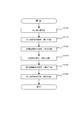
- the method of the present invention includes a first step (S110) for heating molten Al and Mg-containing Zn-plated steel sheets arranged in a sealed container, and an atmosphere inside the sealed container.
- the fifth step (S150) for cooling the inner plated steel sheet is performed in this order.
- atmospheric gas means the gas which exists in the inside of an airtight container, and is a general term such as air
- the airtight container 10 has the arrangement
- the sealed container 10 can take either a sealed state in which inflow of gas from the outside to the inside is substantially impossible or an open state in which the plated steel sheet can be carried from the outside to the inside. It is configured.
- the hermetic container 10 has an opening on its wall surface or bottom surface to which an exhaust pipe 31, a water vapor supply pipe 41, a gas introduction pipe 51, a drain pipe 35 and the like, which will be described later, can be connected, and an open / close valve provided in these pipes.
- the airtight container 10 may be provided with the temperature adjustment mechanisms 20 and 21 which adjust the temperature in an airtight container by heating or cooling the airtight container 10 in the outer wall surface.
- the plated steel plate 1 has a base steel plate and a molten Al, Mg-containing Zn plating layer formed on the surface of the base steel plate.
- the type of the base steel plate is not particularly limited, and for example, a steel plate made of low carbon steel, medium carbon steel, high carbon steel, alloy steel, or the like can be used.
- steel sheets for deep drawing such as low carbon Ti-added steel and low carbon Nb-added steel are preferred as the base steel sheet.
- the molten Al and Mg-containing Zn plating layer only needs to have a composition that is blackened by contact with water vapor.
- the mechanism by which the plating layer is blackened by contact with water vapor is unknown, but one hypothesis is that Zn, Al, Mg having an oxygen-deficient defect structure in the surface of the plating layer and in the plating layer by contact with water vapor. This is presumed to be due to the formation of oxides (eg, ZnO 1-x ) and hydroxides. As described above, when an oxygen-deficient oxide or hydroxide is generated, light is trapped in the defect level, so that the oxide or hydroxide has a black appearance.
- a plating layer having a composition in which Al is 0.1% by mass or more and 60% by mass or less, Mg is 0.01% by mass or more and 10% by mass or less, and Zn is the balance should be suitably blackened by contact with steam. Can do.
- the molten Al- and Mg-containing Zn-plated steel sheets most widely distributed in the market contain about 6% by mass of Al and about 3% by mass of Mg in the plating layer.
- the metal structure having such a plating composition is [Primary Al phase] or [Primary Al phase] and [Zn] in a substrate of [Al / Zn / Zn 2 Mg ternary eutectic structure].
- Single phase] and the plating layer can be suitably blackened by steam treatment.
- Each phase (Al phase, Zn phase, and Zn 2 Mg phase) is intricate in size and shape, and is intricate with each other.
- the Al phase in the primary eutectic Al phase and the Al / Zn / Zn 2 Mg ternary eutectic structure is the Al ”phase (Zn solid solution at high temperature in the Al—Zn—Mg ternary equilibrium diagram). This is a solid solution of Al and contains a small amount of Mg.
- the Al "phase at a high temperature usually appears separated into a fine Al phase and a fine Zn phase at room temperature.
- the Zn phase in the ternary eutectic structure is a Zn solid solution in which a small amount of Al is dissolved, and in some cases, Mg is further dissolved.
- the Zn 2 Mg phase in the ternary eutectic structure is an intermetallic compound phase in the vicinity of a point where Zn is about 84 mass% in the Zn—Mg binary equilibrium diagram.
- the plating layer that can be suitably blackened by contact with water vapor has [Primary Al phase] or [Primary crystal] in the [Al / Zn / Zn 2 Mg ternary eutectic structure] substrate.
- the Al phase] and [Zn single phase] are not limited to those having a mixed metal structure, and the primary crystal may be a Zn phase, and is contained in the plating layer, for example, Si.
- An intermetallic compound derived from another element may be a primary crystal.
- an intermetallic compound of Zn 2 Mg or Zn 11 Mg 2 may be used.
- the thickness of the plating layer is not particularly limited, but is preferably 3 ⁇ m or more and 100 ⁇ m or less. If the thickness of the plating layer is 3 ⁇ m or more, scratches that occur when the plated steel sheet 1 is handled are difficult to reach the base steel sheet, and the black appearance retainability and corrosion resistance are higher. Moreover, when the thickness of the plating layer is 100 ⁇ m or less, peeling between the plating layer and the base steel plate in the processed portion is less likely to occur due to the difference in ductility between the plating layer and the base steel plate when compressed.
- the shape of the plated steel sheet 1 is not particularly limited as long as the plating layer in the region to be blackened can come into contact with water vapor.
- the shape of the plated steel plate 1 may be a flat shape (for example, a flat plate shape) or a bent shape (for example, a coil shape).
- coil shape means the shape by which the metal strip comprised by the plated steel plate 1 was wound at intervals in the radial direction. From the viewpoint of ease of arrangement inside the sealed container 10 and ease of conveyance before and after that, the shape of the plated steel sheet 1 is preferably coiled.
- the minimum distance between the adjacent surfaces in the radial direction is 0.05 mm so that the water vapor can easily enter the radial interval of the plated steel plate 1. It is preferable to ensure the above.
- a spacer can be arrange
- the spacer may have any shape as long as water vapor can be sufficiently distributed to the plating layer on the surface of the coiled plated steel sheet.
- the spacer may be a linear spacer or a planar spacer.
- the linear spacer is a wire disposed on a part of the plated steel sheet surface
- the planar spacer is a flat member disposed on at least a part of the plated steel sheet surface.
- the area where the plated steel sheet surface and the spacer are in contact with each other is preferably small, and the contact area at one contact point is preferably 15 mm 2 or less.
- the material of the spacer is not particularly limited as long as it is not significantly deteriorated, ignited, fused or melted with the plated steel sheet during the water vapor treatment, but the material is preferably a metal or a resin, and may be a material having water vapor permeability. More preferred.
- the portion that is not blackened may be masked with an aluminum tape or a resin tape.
- the plated steel sheet 1 when the plated steel sheet 1 is disposed inside the sealed container 10, it may be disposed in a single layer or may be stacked.
- the coiled plated steel sheet 1 can be arranged with eye-up.
- the two or more coiled plated steel sheets 1 when two or more coiled plated steel sheets 1 are blackened simultaneously, the two or more coiled plated steel sheets 1 can be placed in an airtight container by overlapping each other with eye-up.
- positioning in an airtight container in order to make water vapor
- the plated steel plate 1 processed into an arbitrary shape may be arranged in a closed container to be blackened.
- a shelf may be provided in the sealed container 10 and the processed plated steel sheet may be placed on the shelf.
- the processed plated steel sheet may be suspended from the shelf.
- the plated steel sheet 1 is heated in the presence of a gas (low steam gas) whose dew point is always lower than the temperature of the plated steel sheet.
- the atmospheric gas present inside the sealed container 10 is a low water vapor gas.
- the low water vapor gas may be air, but may be replaced with an inert gas such as nitrogen as long as the plated steel sheet 1 can be blackened.
- the atmosphere may be replaced with an atmosphere having a lower dew point than the atmosphere.
- the low water vapor gas can be introduced into the sealed container 10 from the gas introduction unit 50 connected to the sealed container 10.
- a gas having a dew point lower than the plated steel plate temperature is referred to as “low steam gas”.
- the temperature of the plated steel sheet 1 before heating is usually around room temperature, and the heat capacity of the plated steel sheet 1 is large. Therefore, when the plated steel sheet 1 is heated in the presence of an atmosphere gas containing a large amount of water vapor, the dew point is equal to or higher than the plated steel sheet temperature, the atmosphere gas in the vicinity of the surface of the plated steel sheet 1 is cooled by the plated steel sheet 1 to the plated steel sheet surface. Condensation may occur. As a result, water vapor cannot be brought into contact with the portion of the plated steel sheet 1 where condensation has occurred, and blackening is hindered, and the plating layer may not be uniformly blackened. Further, the surface of the plated steel sheet is corroded by condensation, and the appearance may be impaired by being covered with white rust.
- the plated steel sheet 1 in the first step (S110), is heated in the presence of a low water vapor gas.
- the dew point of the atmospheric gas in the first step (S110) is normal temperature or lower.
- the atmospheric gas in this step can be the atmosphere.
- the temperature of the plated steel sheet 1 increases with heating, if the dew point of the atmospheric gas at the start of heating is lower than the temperature of the plated steel sheet 1, the dew point of the atmospheric gas is usually always the temperature of the plated steel sheet. Therefore, the occurrence of condensation on the plated steel sheet 1 is prevented.
- the heating of the plated steel sheet 1 in the first step (S110) is performed until the surface temperature of the plating layer reaches a temperature at which the plating layer is blackened by contact with water vapor (hereinafter also referred to as “black processing temperature”). .
- heating is preferably performed until the surface temperature of the plated steel sheet 1 installed in the sealed container 10 exceeds the black processing temperature while being measured with a temperature measurement sensor.
- the surface temperature may not rise uniformly, and the surface temperature may be uneven. Therefore, it is preferable that heating is performed while measuring the temperature of a plurality of points or regions on the surface of the plated steel sheet, or the entire surface, and heating is performed until the lowest measured surface temperature reaches the black processing temperature. . By accumulating the measurement data, it is possible to set the heating condition and finish the heating without actually measuring the temperature.
- the black processing temperature can be arbitrarily set according to the composition of the plating layer (for example, the amount of Al and Mg in the plating layer) or thickness, or the required brightness, but is 50 ° C. or higher and 350 ° C. or lower. It is preferable that the temperature is 105 ° C. or higher and 200 ° C. or lower. When the black processing temperature is 105 ° C. or higher, blackening can be performed in a shorter time. In addition, if the black processing temperature is 350 ° C. or lower, the blackening device can be reduced in size, energy consumption required for heating the steam and the plated steel sheet 1 during blackening can be suppressed, and the black color of the plating layer can be reduced. The degree of conversion can be easily controlled.
- the method for heating the plated steel sheet 1 is not particularly limited as long as the surface of the plating layer can be brought to the black processing temperature.
- a heating device 24 such as a sheath heater may be provided in the hermetic container 10 to heat the atmospheric gas in the hermetic container 10 to heat the plated steel sheet 1, or the temperature provided on the outer wall surface of the hermetic container 10.
- the plated steel sheet 1 may be heated by adjusting the temperature in the sealed container 10 by the adjusting mechanisms 20 and 21.
- the heating device 24 such as a sheath heater and the temperature adjusting mechanisms 20 and 21 may be used alone, or they may be used in combination.
- the atmospheric gas in the sealed container is heated, if the atmospheric gas is stirred by the stirring device 70 such as the circulation fan 71 provided in the sealed container 10, the plated steel sheet 1 is efficiently heated in a short time without unevenness. Is possible.
- the atmospheric gas in the sealed container 10 is exhausted through the exhaust pipe 31, and the pressure of the gas in the sealed container 10 is set to 70 kPa or less.
- the pressure of the gas in the sealed container 10 can be set to the above range by discharging the atmospheric gas in the sealed container 10 with an exhaust pump (not shown) installed outside the sealed container 10.
- the atmospheric gas may be exhausted only once, or in order to reduce the amount of gas components other than water vapor remaining in the sealed container 10, the exhaust of the atmospheric gas and the gas The introduction of the low water vapor gas from the introduction pipe 51 may be repeated.
- the atmospheric gas in the sealed container 10 is exhausted in the second process (S120) to lower the gas pressure in the sealed container 10, thereby being introduced in the third process (S130) described later.
- Water vapor can be sufficiently distributed to the gaps between the plated steel sheets 1.
- the entire plating layer to be blackened can be more uniformly steamed, and blackening unevenness can be made difficult to occur.
- the exhaust gas in the second step (S120) can reduce the oxygen concentration in the sealed container 10 after introducing the water vapor in the third step (S130) to 13% or less.
- the gas pressure in the sealed container 10 is preferably 70 kPa or less, and more preferably 50 kPa or less.
- the third step (S 130) includes a plurality of points or regions in the surface of the plating layer, or the temperature at the highest measured temperature among the entire surface.
- the temperature difference is preferably 30 ° C. or less, preferably 20 ° C. or less, more preferably 10 ° C. or less, when the measured temperature is the lowest. That is, it is more preferable that the third step (S130) is performed after the surface temperature of the entire plated steel plate becomes uniform.
- the third step (S130) is performed after the surface temperature of the entire plated steel plate becomes uniform.
- the atmospheric temperature in the airtight container 10 during a water vapor process is 105 degreeC or more, and the relative humidity in the airtight container 10 during a water vapor process is 80% or more and 100% or less.
- the atmospheric temperature is 105 ° C. or higher and the relative humidity of water vapor to 80% or higher, blackening can be performed in a shorter time.
- the ambient temperature is set to 105 ° C. or higher, the plating layer is sufficiently blackened, and for example, the brightness L of the plating layer in the L * a * b * color space is 60 or less, preferably 40 or less, more preferably 35.
- the lightness (L * value) of the plating layer surface is measured by a spectral reflection measurement method using a spectral color difference meter. Moreover, since it becomes difficult for water to condense by setting the atmospheric temperature to 105 ° C. or higher, it is possible to suppress the occurrence of condensation on the inside of the sealed container 10 and the plating layer surface.
- the ambient temperature is more preferably 105 ° C. or more and 350 ° C. or less, and further preferably 105 ° C. or more and 200 ° C. or less. More preferably, the relative humidity is 100%.
- the oxygen concentration in the airtight container 10 during the water vapor treatment is 13% or less, and by making the oxygen concentration 13% or less, occurrence of unevenness in blackening can be suppressed.
- the temperature of the atmospheric gas inside the sealed container is referred to as “atmospheric temperature”.
- the ambient temperature can be measured by a gas temperature measuring unit 62 provided inside the sealed container.
- the heating method controls the temperature and relative humidity inside an airtight container to the said range.
- the temperature adjustment mechanisms 21 and 20 may be used, and a heating device 24 such as a sheath heater provided in the sealed container 10 may be used.
- the value of the pressure gauge 61 measured inside the sealed container 10 is set to the temperature at that time. What is divided by the saturated water vapor pressure below is the relative humidity in the sealed container 10.
- a value of 61 is the total pressure of the water vapor partial pressure and the hydrogen partial pressure.
- Zn reacts with water vapor to generate an oxide or hydroxide of Zn, and hydrogen gas is generated at the same time.
- the reaction formulas are considered to be the following formulas (1) and (2).
- hydrogen gas accumulates in the hermetic container 10 and the relative humidity decreases due to the coexistence of water vapor and hydrogen gas.
- the present inventors considered that such a phenomenon occurred in the sealed container 10, and thus the plating layer could not be sufficiently brought into contact with water vapor, and the black-plated steel sheet 1 having a uniform appearance could not be obtained.
- a certain amount of atmospheric gas is introduced from the inside of the sealed container 10.
- the water vapor is discharged and water vapor is further introduced into the sealed container. That is, hydrogen gas generated inside the hermetic container 10 by discharging a certain amount of atmospheric gas from the hermetic container 10 and performing the third step (S130) while further introducing water vapor into the hermetic container 10.
- the atmospheric gas containing the gas is discharged out of the sealed container 10.
- the sealed container 10 has a one-component system consisting of only water (water vapor), and the total pressure and temperature in the sealed container 10 are Does not become two independent variables. If one of the saturated water vapor pressure and the saturated vapor temperature is determined, the other is determined. In such a state, the total pressure and temperature in the sealed container 10 need only be controlled whichever has better controllability, and the advantage of easy control is born. As a result, the generated hydrogen gas can be discharged efficiently and reliably without complicating the management of water vapor treatment in the manufacturing process, and the plating layer is uniformly blackened by spreading sufficient water vapor throughout the plated steel sheet. It becomes possible to manufacture the black-plated steel sheet 1 with better appearance.
- reaction formula (2) When the reaction formula (2) occurs, according to the reaction formula (2), 2 mol of water vapor is consumed and 1 mol of hydrogen gas is generated. The amount of water vapor necessary for the blackening of the plating layer is ensured even if it decreases. That is, even if the pressure in the sealed container is reduced to about 80% of the set value, the generated hydrogen gas can be discharged and the amount of water vapor necessary for blackening the plating layer can be supplied.
- the temperature in the sealed container during the steam treatment may be higher than the set black processing temperature. That is, the higher the temperature, the higher the saturated water vapor pressure. In such a case, the water vapor necessary for blackening the plating layer is increased by increasing the pressure to a range of about 120% according to the temperature in the sealed container. A sufficient amount can be supplied.
- the pressure during the steam treatment in the sealed container is preferably controlled in the range of 80 to 120% with respect to the predetermined value of the set pressure according to the reaction state in the sealed container.
- the discharge of atmospheric gas and the introduction of water vapor may be performed continuously from the start to the end of the third step (S130) or may be performed only once. Further, it may be performed a plurality of times at regular intervals.
- the atmosphere gas inside the sealed container 10 is stirred by the stirring unit 70 after introducing water vapor into the sealed container 10 or during the blackening process during the introduction. May be.
- the treatment time for the steam treatment can be arbitrarily set according to the composition of the plating layer (for example, the amount of Al and Mg in the plating layer) or thickness, and the required brightness. It is preferable to carry out for about 24 hours.
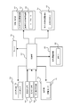
- the amount of water vapor introduced into the sealed container 10 and the exhaust amount of the atmospheric gas in the sealed container 10 are configured to be adjustable. As shown in FIG. 2, plating is performed by an introduction water vapor adjustment mechanism 40 that adjusts the amount of water vapor introduced into the sealed container 10 and an exhaust gas adjustment mechanism 30 that adjusts the exhaust amount of the atmospheric gas in the sealed container 10. The amount of water vapor in the sealed container 10 necessary for blackening the layer is adjusted to maintain a predetermined pressure.
- each of the adjustment mechanisms 30 and 40 is provided with a plurality of pipes (20A, 25A, and 80A in the embodiment) having different nominal diameters, and the exhaust valves 322, 324, and 326 (hereinafter collectively referred to as the exhaust valves) provided in the pipes.
- the steam supply valves 422, 424, and 426 (hereinafter collectively referred to as “steam supply valve 42”) are controlled to be opened and closed by a control unit 90 described later, and the amount of steam introduced.
- the pressure in the sealed container is maintained at an appropriate predetermined value.
- the opening of the exhaust valve 32 of the exhaust adjustment mechanism 30 is set to a predetermined opening so that the necessary amount of water vapor can be secured in the sealed container 10, and the steam supply valve 42 of the introduction steam adjustment mechanism 40 is set.
- the opening is variably controlled.
- the present invention is not necessarily limited to the above embodiment, and the opening degree of the steam supply valve 42 of the introduction steam adjustment mechanism 40 is set to a predetermined opening degree, and the opening degree of the exhaust valve 32 of the exhaust adjustment mechanism 30 is variably controlled. May be. Further, both the opening degree of the exhaust valve 32 of the exhaust adjustment mechanism 30 and the opening degree of the water vapor supply valve 42 of the introduction water vapor adjustment mechanism 40 may be controlled to be adjusted in a timely manner.
- the reaction according to the above reaction formula (1) is an exothermic reaction, it is considered that the temperature of the plated steel sheet 1 increases as the blackening process proceeds. At that time, if the pressure in the sealed container remains at the predetermined value, the relative humidity is lowered for the plated steel sheet 1, and from the viewpoint of performing the blackening reaction in a short time. It is not preferable. Therefore, at least one of the opening degree of the exhaust valve 32 of the exhaust adjustment mechanism 30 and the opening degree of the steam supply valve 42 of the introduction water vapor adjustment mechanism 40 is adjusted so that the pressure in the sealed container is predetermined. While maintaining the value, a larger amount of water vapor than before is introduced into the sealed container, so that the relative humidity for the plated steel sheet 1 can be increased and the blackening reaction can proceed.
- a 4th process In a 4th process (S140), after returning the pressure inside the airtight container 10 to atmospheric pressure once, the atmospheric gas inside the airtight container 10 is exhausted, and the gas pressure inside an airtight container is made 70 kPa or less.
- the atmospheric pressure release valve (not shown) provided in the sealed container.
- an exhaust pump (not shown) installed outside the sealed container is used, and the atmospheric gas in the sealed container 10 is discharged through the exhaust pipe 31. As a result, the pressure in the sealed container 10 can be lowered.
- the fourth step (S140) when the plated steel sheet 1 is cooled in the fifth step (S150), which will be described later, with water vapor remaining inside the sealed container 10, it remains in the gaps of the plated steel sheet 1 and the like. Water vapor may be cooled and condensed, and condensation may occur on the surface of the plated steel sheet 1 or inside the sealed container 10. When dew condensation occurs on the surface of the plated steel sheet 1, moisture may adhere to the surface of the plated steel sheet 1, which may cause unevenness in the black color of the plated steel sheet 1. Therefore, in the fourth step (S140), after the pressure inside the sealed container 10 is once returned to atmospheric pressure, the atmospheric gas inside the sealed container 10 is exhausted to reduce the amount of water vapor inside the sealed container 10. Yes.
- the gas pressure in the sealed container 10 is preferably 70 kPa or less, and more preferably 30 kPa or less.
- a gas (low water vapor gas) whose dew point is always lower than the temperature of the plated steel sheet is introduced from the gas introduction pipe 51 into the sealed container 10 to cool the plated steel sheet 1.
- the gas introduced in the fifth step (S150) is preferably not heated, but may be heated to a temperature lower than the ambient temperature in the sealed container 10 as necessary.
- the low water vapor gas introduced in the fifth step (S150) can be the atmosphere, nitrogen gas, or inert gas.
- the sealed container 10 is opened to the atmosphere and the atmosphere is introduced. It is preferable to do.
- the temperature of the atmospheric gas in the sealed container 10 may be lowered using the temperature adjusting mechanisms 20 and 21 to cool the plated steel sheet 1.
- the atmospheric gas in the sealed container is cooled, if the atmospheric gas is stirred by the stirring device 70 such as the circulation fan 71 provided in the sealed container 10, the plated steel sheet 1 is efficiently cooled in a short time without unevenness. Is possible.
- FIG. 2 is a schematic sectional view showing an example thereof.
- An airtight container 10 having an arrangement part 12 that can be arranged, a ceiling temperature adjusting mechanism 21 that heats (or cools) the inside of the airtight container 10, a vertical wall temperature adjusting mechanism 20, a heating device 24 such as a sheath heater, and an airtight
- An exhaust adjustment mechanism 30 that exhausts atmospheric gas inside the container 10 and an introduction water vapor adjustment mechanism 40 that introduces water vapor into the closed container 10 are provided.
- the apparatus of the present invention further includes a gas introduction part 50 for introducing a gas containing the atmosphere into the sealed container 10 and an atmospheric pressure release valve (not shown) for returning the pressure inside the sealed container 10 to atmospheric pressure. ).
- the apparatus of the present invention further includes a temperature measuring unit 60 that measures the temperature of the plated steel sheet 1, a pressure measuring unit 61 that measures the pressure in the sealed container 10, and a gas temperature measuring unit 62 that measures the temperature of the atmospheric gas. It may be.
- stirring parts 70 such as the circulation fan 71 which stirs the atmospheric gas inside the airtight container 10. FIG. Further, as shown in FIG.
- the apparatus of the present invention includes temperature adjusting mechanisms 21 and 20, a heating device 24 such as a sheath heater, an exhaust adjusting mechanism 30, an introduced water vapor adjusting mechanism 40, a gas introducing unit 50, and a stirring unit.
- a control unit 90 that controls the opening / closing operation of each valve device to manufacture the black-plated steel sheet 1 may be provided.
- the control part 90 may control operation
- the sealed container 10 has a bottom frame 8 and an upper cover 9.
- the bottom frame 8 includes an arrangement portion 12 on which the plated steel plate 1 is arranged.
- the upper cover 9 has an upper cover ceiling portion 13 whose ceiling surface is formed in a dome shape, and an upper cover vertical wall portion 14 whose side surface is formed in a circular cylindrical shape.
- the upper cover 9 is configured by a shape in which the lower part is opened.
- the ceiling part temperature adjustment mechanism 21 and the vertical wall part temperature adjustment mechanism 20 which can heat and cool the inside of the sealed container 10 by flowing a fluid are separately provided on the outer wall of the sealed container 10. It has been.
- the airtight container 10 is not cooled by the ceiling temperature adjusting mechanism 21 when the inside of the airtight container is cooled, and the vertical wall temperature adjusting mechanism 20 is not cooled. This is because the airtight container 10 is cooled.
- the sealed container 10 is configured by sealing the bottom frame 8 and the upper cover 9, and the internal gas pressure is reduced by exhausting atmospheric gas, the internal pressure is increased by introducing water vapor, and heating and cooling are performed. It has enough strength to withstand
- a water vapor supply pipe 41 for introducing water vapor from a water vapor supply source, an exhaust pipe 31, a gas introduction pipe 51, and a drain pipe 35 for discharging atmospheric gas, water vapor and the like in the sealed container 10.
- the inside of the airtight container 10 can be made into the airtight state by closing the on-off valve provided in these piping.
- the plated steel plate 1 is disposed on the disposition portion 12 provided on the bottom frame 8.
- the plated steel sheet 1 may be laminated by the spacer 2.
- the disposing portion 12 has a through hole 12 ⁇ / b> A for blowing the atmospheric gas flowing from the upper part of the plated steel plate 1 to the lower part of the plated steel plate 1 to the vicinity of the circulation fan 71.
- the exhaust adjustment mechanism 30 has an exhaust pipe 31, an exhaust valve 32, and an exhaust pump (not shown).
- the exhaust pipe 31 is a pipe provided through the bottom frame 8 so as to communicate the inside of the sealed container 10 and the outside of the sealed container 10.
- the atmospheric gas such as low-water vapor gas
- the atmospheric gas such as water vapor gas or generated hydrogen gas
- pipes 332, 334, and 336 having different nominal diameters are connected to adjust the amount of water vapor in the sealed container during the water vapor treatment.
- An exhaust pipe 31 is provided.
- An exhaust valve 32 is provided in each of the pipe 332, the pipe 334, and the pipe 336.
- a pipe having a nominal diameter of 20 A is used for the pipe 332
- a pipe having a nominal diameter of 25 A is used for the pipe 334
- a pipe having a nominal diameter of 80 A is used for the pipe 336.
- the control unit 90 controls the opening and closing of the exhaust valve 32 so that the exhaust amount can be finely and accurately adjusted.
- the present invention is not limited to this embodiment, and the nominal diameter and number of exhaust pipes can be set as necessary.
- the exhaust adjustment mechanism 30 is comprised so that the pressure of the gas in the airtight container 10 can be 70 kPa or less by exhausting atmospheric gas.
- the drain pipe 35 is a pipe provided through the bottom frame 8 so as to communicate the inside of the sealed container 10 and the outside of the sealed container 10.
- the liquid (condensed water or the like) inside the sealed container 10 is discharged to the outside through the drain pipe 35.
- the introduced water vapor adjusting mechanism 40 has a water vapor supply pipe 41 and a water vapor supply valve 42, and adjusts the amount of water vapor supplied into the sealed container 10 with the water vapor supply valve 42.
- the water vapor supply valve 42 is closed and the supply of water vapor into the sealed container 10 through the water vapor supply pipe 41 is shut off.
- the pipe 432, the pipe 434, the pipe 436, Exhaust pipes 41 to which pipes having different nominal diameters are connected are provided, and each pipe is provided with a water vapor supply valve 42.
- a pipe having a nominal diameter of 20 A is used for the pipe 432
- a pipe having a nominal diameter of 25 A is used for the pipe 434
- a pipe having a nominal diameter of 80 A is used for the pipe 436.
- the water vapor supply valve 42 is controlled to be opened and closed so that the amount of introduced water vapor can be adjusted finely and accurately.
- the present invention is not limited to this embodiment, and the nominal diameter and number of the water vapor supply pipe 41 can be set as necessary.
- the gas introduction unit 50 includes a gas introduction pipe 51 and a gas introduction valve 52.
- the gas introduction pipe 51 is a pipe provided through the bottom frame 8 so as to communicate the inside of the sealed container 10 with the outside of the sealed container 10 or a gas supply source (not shown).
- the gas introduction unit 50 can be used, for example, to introduce a low water vapor gas into the sealed container 10 in the first step (S110) and the fifth step (S150).
- the temperature measuring unit 60 is a plurality of temperature sensors installed in contact with different areas of the surface of the plated steel sheet 1 and measures the temperature of the plated steel sheet 1 using, for example, a thermocouple.
- a thermocouple may be inserted between the coils.
- the pressure measuring unit 61 is a pressure gauge for measuring the pressure inside the sealed container 10.
- This pressure gauge includes a pressure gauge capable of measuring the gauge pressure in the first step (S110), the third step (S130), and the fifth step (S150), and the second step (S120) and the fourth step (S140).
- a vacuum pressure gauge capable of measuring a pressure below atmospheric pressure is provided, and each pressure gauge may be switched and used.
- the gas temperature measuring unit 62 is a temperature sensor for measuring the temperature of the atmospheric gas inside the sealed container 10, and for example, a thermocouple can be used.
- the temperature sensor is not provided at only one place, but may be provided at a plurality of places inside the sealed container 10 and switched appropriately.
- the stirring unit 70 includes a circulation fan 71 disposed on the bottom frame 8 and a drive motor 72 that rotationally drives the circulation fan 71.
- the drive motor 72 rotates the circulation fan 71, the atmospheric gas inside the sealed container 10 during the water vapor treatment flows from the side of the placement section 12 to the inner wall surface of the sealed container 10 as indicated by arrows in FIG. Flows into the gap between the two, passes through the outer peripheral surface of the plated steel sheet 1, and flows into the gap between the metal strips from the top of the plated steel sheet 1.
- the stirring unit 70 is not used only during the steam treatment, and may be used in the heating process or the cooling process of the plated steel sheet 1.
- FIG. 3 is an Example of this invention
- movement of the apparatus which manufactures the black plating steel plate of this invention, and its control system are demonstrated in detail.
- the control unit 90 introduces the temperature adjustment mechanisms 20 and 21, the heating device 24 such as a sheath heater, the exhaust adjustment mechanism 30, and the like as follows.
- the operations of the water vapor adjusting mechanism 40, the gas introducing unit 50, and the stirring unit 70 are controlled.
- the control unit 90 heats the inside of the sealed container 10 in the presence of low steam gas using the temperature adjusting mechanism 20, 21 or / and a heating device 24 such as a sheath heater. Then, the plated steel sheet 1 is heated. At this time, the control unit 90 operates each of the heating means until the temperature of the plating layer measured by the temperature measurement unit 60 reaches the black processing temperature.
- the target temperature of the black processing temperature is 105 ° C.
- the circulation fan 71 may be rotated as necessary to control heating while circulating the atmospheric gas inside the sealed container.
- the control unit 90 opens the exhaust valve 32 of the exhaust adjustment mechanism 30 and operates an exhaust pump (not shown) to thereby increase the gas pressure in the sealed container 10.
- the atmospheric gas in the sealed container 10 is discharged through the exhaust pipe 31 until the pressure reaches 70 kPa or less.
- the exhaust valve 32 is closed. Before opening the exhaust valve 32 of the exhaust adjustment mechanism 30 and operating the exhaust pump, an operation is performed to open the atmospheric pressure release valve (not shown) and return the pressure in the sealed container 10 to atmospheric pressure once. Also good.
- the control unit 90 opens the steam supply valve 42 of the introduced steam adjustment mechanism 40 and opens the sealed container 10 from the steam supply source. To supply water vapor. Thereby, the water vapor from the water vapor supply source is introduced into the sealed container 10 through the water vapor supply pipe 41.
- the control unit 90 has recognized that the difference between the lowest temperature and the highest temperature among the temperatures measured by the plurality of temperature measurement units 60 is within the predetermined range.
- the steam supply valve 42 can be opened. At this time, the introduced steam may be heated by a steam heater (not shown) as necessary.
- control unit 90 may rotate the circulation fan 71 by driving the drive motor 72 of the stirring unit 70 as necessary, and stir and circulate the atmospheric gas including water vapor in the sealed container 10.
- the control unit 90 includes an introduction water vapor adjustment mechanism 40 that adjusts the amount of water vapor introduced into the sealed container 10, and an exhaust adjustment mechanism 30 that adjusts the exhaust amount of atmospheric gas in the sealed container 10. And the amount of water vapor in the sealed container that is always necessary for blackening the plating layer is adjusted to appropriately exclude the hydrogen gas generated in the sealed container, and at an appropriate relative humidity (the target value is 100). %) Is maintained. That is, the control unit 90 controls the opening and closing of the exhaust valve 32 and the water vapor supply valve 42 provided for each of the pipes having different nominal diameters of the adjustment mechanisms 30 and 40, thereby introducing the water vapor amount and the atmospheric gas exhaust amount. Adjustments are made.
- the control unit 90 When adjusting the amount of water vapor in the sealed container 10, since the amount of water vapor necessary for the blackening treatment is determined according to the surface area of the plated steel sheet 1 placed in the sealed container 10, the control unit 90.
- the opening of the exhaust valve 32 of the exhaust adjustment mechanism 30 is fixedly controlled to a predetermined opening so that the necessary amount of water vapor can be secured in the sealed container 10, and the steam supply valve 42 of the introduction steam adjustment mechanism 40 is opened.
- the degree is variably controlled.
- the opening degree of the steam supply valve 42 of the introduction steam adjustment mechanism 40 may be fixedly controlled to a predetermined opening degree, and the opening degree of the exhaust valve 32 of the exhaust adjustment mechanism 30 may be variably controlled. Both the opening degree of the exhaust valve 32 of the mechanism 30 and the opening degree of the water vapor supply valve 42 of the introduction water vapor adjusting mechanism 40 may be adjusted and controlled in a timely manner.
- the control unit 90 uses the measurement data of the pressure measuring unit 61. Monitoring is always performed and control is performed so that the necessary pressure is maintained in the sealed container 10. Thereby, the amount of water vapor necessary for the water vapor treatment can be secured in the sealed container 10.
- a saturated water vapor pressure of 121 kPa corresponding to the temperature of 105 ° C. in the sealed container 10 is set in the control unit 90 as the set pressure in the sealed container 10 during the steam treatment.
- the amount of water vapor to be introduced or discharged may be controlled, or the amount of water vapor to be introduced and the amount of water vapor to be discharged may be timely controlled so as to always maintain a constant value of a predetermined pressure.
- the control unit 90 closes the water vapor supply valve 42 of the introduction water vapor adjustment mechanism 40 and connects the inside and the outside of the sealed container 10 through the water vapor supply pipe 41. Block the gas flow between them. Thereafter, the exhaust valve 32 of the exhaust adjustment mechanism 30 is opened, and an exhaust pump (not shown) is operated to discharge the atmospheric gas in the sealed container 10. Thereby, the gas pressure in the airtight container 10 is made 70 kPa or less. When the gas pressure inside the sealed container 10 becomes 70 kPa or less, the control unit 90 closes the exhaust valve 32 of the exhaust adjustment mechanism 30 and distributes the gas between the inside and the outside of the sealed container 10 through the exhaust pipe 31. Shut off.
- the control unit 90 opens the gas introduction valve 52 of the gas introduction unit 50.
- the gas whose dew point is always lower than the plated steel plate temperature is introduced into the sealed container 10 through the gas introduction pipe 51.
- the atmosphere is introduced until the pressure of the gas in the sealed container 10 reaches 101 kPa (approximately the same as the atmospheric pressure).
- the plated steel sheet 1 is cooled by the gas thus introduced (atmosphere in this embodiment).
- the control unit 90 may control the opening of the drain valve 36 at any point in time, including cooling the plated steel plate 1, and discharge condensed water in the sealed container 10 to the outside of the sealed container 10. Control of the operation of the drain valve 36 may be performed only once or a plurality of times during the operation of the apparatus of the present invention, or as long as the plating layer is blackened to a desired level. The drain valve 36 may remain closed throughout operation.
- the method of the present invention appropriately discharges hydrogen gas generated during the steam treatment of the plated steel sheet and supplies it with an appropriately controlled amount of water vapor necessary for the steam treatment, it is more uniformly blackened and looks good Therefore, it is expected to contribute to further popularization of the blackened plated steel sheet.
Landscapes
- Chemical & Material Sciences (AREA)
- Engineering & Computer Science (AREA)
- Organic Chemistry (AREA)
- Materials Engineering (AREA)
- Mechanical Engineering (AREA)
- Metallurgy (AREA)
- Chemical Kinetics & Catalysis (AREA)
- Physics & Mathematics (AREA)
- Thermal Sciences (AREA)
- Crystallography & Structural Chemistry (AREA)
- Inorganic Chemistry (AREA)
- Coating With Molten Metal (AREA)
- Chemical Treatment Of Metals (AREA)
- Other Surface Treatments For Metallic Materials (AREA)
Abstract
Description
本願発明に係る黒色めっき鋼板を製造する方法は、AlおよびMgを含有する溶融Al、Mg含有Znめっき鋼板を密閉容器の内部で水蒸気に接触させて黒色めっき鋼板を製造する方法である。
第1工程(S110)では、密閉容器の内部に配置しためっき鋼板を加熱する。
第2工程(S120)では、密閉容器10内の雰囲気ガスを、排気配管31を通じて排気し、密閉容器10内の気体の圧力を70kPa以下にする。例えば、密閉容器10外に設置した排気ポンプ(図示せず。)で、密閉容器10の中の雰囲気ガスを排出することで、密閉容器10内の気体の圧力を上記範囲にすることができる。第2工程(S120)においては、雰囲気ガスの排気を1回のみ行ってもよいし、密閉容器10内に残存する水蒸気以外の気体成分の量をより少なくするため、雰囲気ガスの排気と、ガス導入配管51からの低水蒸気ガスの導入を繰り返し行ってもよい。
第3工程(S130)では、密閉容器10内に水蒸気を導入してめっき鋼板1のめっき層を黒色化する。すなわち、第3工程(S130)では、めっき鋼板1に対して、水蒸気処理を行う。
(1)Zn + H2O → ZnO + H2
(2)Zn + 2H2O → Zn(OH)2 + H2
(3)密閉容器に導入される水蒸気量=排出される正味の水蒸気量+発生した水素ガス量
第4工程(S140)では、密閉容器10の内部の圧力をいったん大気圧に戻した後に、密閉容器10の内部の雰囲気ガスを排気して、密閉容器の内部の気体圧力を70kPa以下にする。例えば、密閉容器10の内部の圧力をいったん大気圧に戻すためには、密閉容器に設けた大気圧開放弁(図示せず。)を開くことで行うことができる。また、密閉容器10内の気体圧力を70kPa以下とするためには、密閉容器外に設置した排気ポンプ(図示せず。)使用し、密閉容器10内の雰囲気ガスを、排気配管31を通じて排出することで密閉容器10内の圧力を低くすることができる。
第5工程(S150)では、密閉容器10の内部に露点が常にめっき鋼板温度未満であるガス(低水蒸気ガス)をガス導入管51から導入してめっき鋼板1を冷却する。第5工程(S150)で導入されるガスは、加熱されていないことが好ましいが、必要に応じて、密閉容器10内の雰囲気温度よりも低温に加熱されていてもよい。
(装置の構成)
本願発明に係る黒色めっき鋼板を製造する装置(以下、「本発明の装置」ともいう。)は、その一例を示す模式断面図である図2に示されているように、めっき鋼板1を取り出し可能に配置できる配置部12を有する密閉容器10と、密閉容器10の内部を加熱(または冷却)する天井部温度調整機構21、縦壁部温度調整機構20、シースヒータ等の加熱装置24と、密閉容器10の内部の雰囲気ガスを排気する排気調整機構30と、密閉容器10の内部に水蒸気を導入する導入水蒸気調整機構40とを有する。本発明の装置は、さらに、密閉容器10の内部に大気を含むガスを導入するガス導入部50や、密閉容器10の内部の圧力を大気圧に戻すための大気圧開放弁(図示せず。)を有していてもよい。本発明の装置は、さらに、めっき鋼板1の温度を測定する温度計測部60や密閉容器10内の圧力を測定する圧力計測部61、雰囲気ガスの温度を計測するガス温度計測部62を有していてもよい。さらに、密閉容器10の内部の雰囲気ガスを撹拌するサーキュレーションファン71などの撹拌部70を有していてもよい。また、本発明の装置は、図3に示されているように、温度調整機構21、20、シースヒータ等の加熱装置24、排気調整機構30、導入水蒸気調整機構40、ガス導入部50、撹拌部70の他、各弁装置の開閉動作を制御して、黒色めっき鋼板1を製造させる制御部90を有していてもよい。また、ドレン配管35およびドレン弁36を有しているとき、制御部90はドレン弁36の動作を制御して、装置内部から外部へ水を排出させてもよい。
以下に、本願発明の実施例である図3を参照して、本願発明の黒色めっき鋼板を製造する装置の例示的な動作と、その制御システムについて詳しく説明する。
上記本願発明の方法によれば、製造工程における水蒸気処理の管理を複雑化させることなくめっき鋼板の水蒸気処理中に発生する水素ガスを効率よく確実に排出することができ、十分な水蒸気をめっき鋼板全体に行き渡らせてめっき層を均一に黒色化し、より見栄えの良い黒色めっき鋼板を提供することができる。
10 密閉容器
Claims (4)
- 溶融Al、Mg含有Znめっき鋼板を密閉容器中で水蒸気と接触させて黒色めっき鋼板を製造する方法であって、
前記密閉容器は、当該密閉容器内に導入される水蒸気の流量と当該密閉容器内から排出される水蒸気の流量とのうち少なくともいずれか一方が可変制御されることにより、当該密閉容器内の圧力が所定値に維持されるように構成されており、
圧力が前記所定値に維持されうる前記密閉容器内において、当該密閉容器内に導入された水蒸気と、前記溶融Al、Mg含有Znめっき鋼板とを接触させる、
ことを特徴とする黒色めっき鋼板の製造方法。 - 前記所定値は、前記密閉容器内の所定の圧力値に対して、80%以上、120%以下の圧力値であることを特徴とする、
請求項1に記載の黒色めっき鋼板の製造方法。 - 溶融Al、Mg含有Znめっき鋼板を密閉容器中で水蒸気と接触させて黒色めっき鋼板を製造する装置であって、
前記溶融Al、Mg含有Znめっき鋼板を内部に配置可能な密閉容器と、
前記密閉容器内に導入される水蒸気の流量と当該密閉容器内から排出される水蒸気の流量とのうち少なくともいずれか一方を可変制御することにより、当該密閉容器内の圧力を所定値に維持可能な圧力制御手段と、を備え、
圧力が前記圧力制御手段によって前記所定値に維持されうる前記密閉容器内において、当該密閉容器内に導入された水蒸気と、前記溶融Al、Mg含有Znめっき鋼板とを接触させることを可能にした、
黒色めっき鋼板の製造装置。 - 前記所定値は、前記密閉容器内の所定の圧力値に対して、80%以上、120%以下の圧力値であることを特徴とする、
請求項3に記載の黒色めっき鋼板の製造装置。
Priority Applications (11)
| Application Number | Priority Date | Filing Date | Title |
|---|---|---|---|
| AU2018210488A AU2018210488B2 (en) | 2017-01-18 | 2018-01-17 | Method and device for manufacturing black plated steel sheet |
| KR1020197020758A KR102269060B1 (ko) | 2017-01-18 | 2018-01-17 | 흑색 도금 강판의 제조 방법 및 그 제조 장치 |
| MX2019008527A MX2019008527A (es) | 2017-01-18 | 2018-01-17 | Metodo y dispositivo para fabricar lamina de acero chapada en negro. |
| EP18742024.5A EP3572552A4 (en) | 2017-01-18 | 2018-01-17 | PROCESS AND DEVICE FOR MANUFACTURING BLACK PLATED STEEL SHEET |
| RU2019125031A RU2762073C2 (ru) | 2017-01-18 | 2018-01-17 | Способ и устройство для изготовления стального листа с черным покрытием |
| US16/478,851 US11512380B2 (en) | 2017-01-18 | 2018-01-17 | Method and device for manufacturing black coated steel sheets |
| CA3050416A CA3050416A1 (en) | 2017-01-18 | 2018-01-17 | Method and device for manufacturing black plated steel sheet |
| CN201880004757.4A CN110225993A (zh) | 2017-01-18 | 2018-01-17 | 黑色镀覆钢板的制造方法以及黑色镀覆钢板的制造装置 |
| MYPI2019004108A MY192083A (en) | 2017-01-18 | 2018-01-17 | Method and device for manufacturing black plated steel sheet |
| BR112019014818-3A BR112019014818B1 (pt) | 2017-01-18 | 2018-01-17 | Método e dispositivo para fabricação de chapas de aço revestidas em preto |
| PH12019501620A PH12019501620A1 (en) | 2017-01-18 | 2019-07-11 | Method and device for manufacturing black plated steel sheet |
Applications Claiming Priority (2)
| Application Number | Priority Date | Filing Date | Title |
|---|---|---|---|
| JP2017-006606 | 2017-01-18 | ||
| JP2017006606A JP6676555B2 (ja) | 2017-01-18 | 2017-01-18 | 黒色めっき鋼板の製造方法およびその製造装置 |
Publications (1)
| Publication Number | Publication Date |
|---|---|
| WO2018135518A1 true WO2018135518A1 (ja) | 2018-07-26 |
Family
ID=62908904
Family Applications (1)
| Application Number | Title | Priority Date | Filing Date |
|---|---|---|---|
| PCT/JP2018/001153 WO2018135518A1 (ja) | 2017-01-18 | 2018-01-17 | 黒色めっき鋼板の製造方法およびその製造装置 |
Country Status (14)
| Country | Link |
|---|---|
| US (1) | US11512380B2 (ja) |
| EP (1) | EP3572552A4 (ja) |
| JP (1) | JP6676555B2 (ja) |
| KR (1) | KR102269060B1 (ja) |
| CN (1) | CN110225993A (ja) |
| AU (1) | AU2018210488B2 (ja) |
| BR (1) | BR112019014818B1 (ja) |
| CA (1) | CA3050416A1 (ja) |
| MX (1) | MX2019008527A (ja) |
| MY (1) | MY192083A (ja) |
| PH (1) | PH12019501620A1 (ja) |
| RU (1) | RU2762073C2 (ja) |
| TW (1) | TWI733975B (ja) |
| WO (1) | WO2018135518A1 (ja) |
Families Citing this family (4)
| Publication number | Priority date | Publication date | Assignee | Title |
|---|---|---|---|---|
| WO2018181685A1 (ja) | 2017-03-31 | 2018-10-04 | 日新製鋼株式会社 | 水蒸気処理製品の製造方法および製造装置 |
| JP6886936B2 (ja) * | 2017-03-31 | 2021-06-16 | 日本製鉄株式会社 | 水蒸気処理製品の製造方法および製造装置 |
| WO2020213688A1 (ja) | 2019-04-19 | 2020-10-22 | 日本製鉄株式会社 | めっき鋼板 |
| KR102438477B1 (ko) * | 2020-12-21 | 2022-08-31 | 주식회사 포스코 | 흑색 도금 강판 및 이의 제조방법 |
Citations (4)
| Publication number | Priority date | Publication date | Assignee | Title |
|---|---|---|---|---|
| JPS5335159B2 (ja) | 1973-02-28 | 1978-09-26 | ||
| JP2012240371A (ja) * | 2011-05-23 | 2012-12-10 | Panasonic Corp | 集成材の製造方法及びその製造方法により製造された集成材 |
| JP2013241671A (ja) * | 2012-04-25 | 2013-12-05 | Nisshin Steel Co Ltd | 黒色めっき鋼板の製造方法および黒色めっき鋼板の成形体の製造方法 |
| JP2013241676A (ja) | 2012-04-25 | 2013-12-05 | Nisshin Steel Co Ltd | 黒色めっき鋼板の製造方法 |
Family Cites Families (11)
| Publication number | Priority date | Publication date | Assignee | Title |
|---|---|---|---|---|
| SU850739A1 (ru) * | 1979-05-15 | 1981-08-10 | Рижское Производственное Объединениевэф Им. B.И.Ленина | Раствор дл дополнительнойОбРАбОТКи ОКСидНыХ пОКРыТий |
| TW359688B (en) * | 1995-02-28 | 1999-06-01 | Nisshin Steel Co Ltd | High anticorrosion Zn-Mg series-plated steel sheet and method of manufacture it |
| TWI239357B (en) * | 1999-07-15 | 2005-09-11 | Jfe Steel Corp | Galvannealed steel sheet and method for manufacturing the same |
| JP5005138B2 (ja) | 2001-08-23 | 2012-08-22 | 株式会社日阪製作所 | 高温湿熱処理装置 |
| JP5097305B1 (ja) * | 2012-04-25 | 2012-12-12 | 日新製鋼株式会社 | 黒色めっき鋼板 |
| JP2013227623A (ja) * | 2012-04-25 | 2013-11-07 | Nisshin Steel Co Ltd | 黒色めっき鋼板の製造方法および黒色めっき鋼板の成形体の製造方法 |
| JP5335159B1 (ja) * | 2012-04-25 | 2013-11-06 | 日新製鋼株式会社 | 黒色めっき鋼板の製造方法および黒色めっき鋼板の成形体の製造方法 |
| EP2963152B1 (en) * | 2013-02-28 | 2020-07-15 | Nippon Steel Coated Sheet Corporation | Steel sheet plated with aluminum-containing zinc and process for producing same |
| MX2017012548A (es) * | 2015-03-31 | 2018-01-25 | Nisshin Steel Co Ltd | Lamina de acero absorbente y radiante de calor, y miembro absorbente y radiante de calor. |
| JP6072952B1 (ja) * | 2016-03-01 | 2017-02-01 | 日新製鋼株式会社 | 黒色めっき鋼板を製造する方法、黒色めっき鋼板を製造する装置および黒色めっき鋼板を製造するシステム |
| CN105821343B (zh) * | 2016-05-24 | 2017-10-27 | 江苏金基特钢有限公司 | 一种特种钢的生产方法 |
-
2017
- 2017-01-18 JP JP2017006606A patent/JP6676555B2/ja active Active
-
2018
- 2018-01-17 KR KR1020197020758A patent/KR102269060B1/ko active IP Right Grant
- 2018-01-17 EP EP18742024.5A patent/EP3572552A4/en not_active Withdrawn
- 2018-01-17 US US16/478,851 patent/US11512380B2/en active Active
- 2018-01-17 CA CA3050416A patent/CA3050416A1/en active Pending
- 2018-01-17 RU RU2019125031A patent/RU2762073C2/ru active
- 2018-01-17 MX MX2019008527A patent/MX2019008527A/es unknown
- 2018-01-17 AU AU2018210488A patent/AU2018210488B2/en active Active
- 2018-01-17 TW TW107101701A patent/TWI733975B/zh active
- 2018-01-17 CN CN201880004757.4A patent/CN110225993A/zh active Pending
- 2018-01-17 WO PCT/JP2018/001153 patent/WO2018135518A1/ja unknown
- 2018-01-17 BR BR112019014818-3A patent/BR112019014818B1/pt active IP Right Grant
- 2018-01-17 MY MYPI2019004108A patent/MY192083A/en unknown
-
2019
- 2019-07-11 PH PH12019501620A patent/PH12019501620A1/en unknown
Patent Citations (4)
| Publication number | Priority date | Publication date | Assignee | Title |
|---|---|---|---|---|
| JPS5335159B2 (ja) | 1973-02-28 | 1978-09-26 | ||
| JP2012240371A (ja) * | 2011-05-23 | 2012-12-10 | Panasonic Corp | 集成材の製造方法及びその製造方法により製造された集成材 |
| JP2013241671A (ja) * | 2012-04-25 | 2013-12-05 | Nisshin Steel Co Ltd | 黒色めっき鋼板の製造方法および黒色めっき鋼板の成形体の製造方法 |
| JP2013241676A (ja) | 2012-04-25 | 2013-12-05 | Nisshin Steel Co Ltd | 黒色めっき鋼板の製造方法 |
Also Published As
| Publication number | Publication date |
|---|---|
| KR20190104545A (ko) | 2019-09-10 |
| RU2762073C2 (ru) | 2021-12-15 |
| EP3572552A4 (en) | 2020-09-09 |
| RU2019125031A (ru) | 2021-02-19 |
| BR112019014818A2 (pt) | 2020-02-27 |
| JP6676555B2 (ja) | 2020-04-08 |
| TW201831709A (zh) | 2018-09-01 |
| RU2019125031A3 (ja) | 2021-07-14 |
| US20200190654A1 (en) | 2020-06-18 |
| JP2018115365A (ja) | 2018-07-26 |
| KR102269060B1 (ko) | 2021-06-24 |
| CA3050416A1 (en) | 2018-07-26 |
| AU2018210488B2 (en) | 2022-12-22 |
| EP3572552A1 (en) | 2019-11-27 |
| PH12019501620A1 (en) | 2020-03-16 |
| BR112019014818B1 (pt) | 2021-10-19 |
| TWI733975B (zh) | 2021-07-21 |
| MX2019008527A (es) | 2019-09-09 |
| CN110225993A (zh) | 2019-09-10 |
| AU2018210488A1 (en) | 2019-08-29 |
| US11512380B2 (en) | 2022-11-29 |
| MY192083A (en) | 2022-07-26 |
Similar Documents
| Publication | Publication Date | Title |
|---|---|---|
| WO2018135518A1 (ja) | 黒色めっき鋼板の製造方法およびその製造装置 | |
| JP6072952B1 (ja) | 黒色めっき鋼板を製造する方法、黒色めっき鋼板を製造する装置および黒色めっき鋼板を製造するシステム | |
| US20130125797A1 (en) | Vertical Heat Treating Furnace | |
| JP6875918B2 (ja) | 黒色めっき鋼板の製造装置および製造システム | |
| JP6854673B2 (ja) | 水蒸気処理用の密閉容器 | |
| JP6832200B2 (ja) | 水蒸気処理用の密閉容器 | |
| JP6905358B2 (ja) | 水蒸気処理用の密閉容器 | |
| JP6905376B2 (ja) | 水蒸気処理製品の製造方法および製造装置 | |
| JP2018172746A (ja) | 水蒸気処理方法および水蒸気処理装置 | |
| JP2018172744A (ja) | 水蒸気処理方法および水蒸気処理装置 | |
| JP2019056171A (ja) | 水蒸気処理製品の製造方法および製造装置 | |
| JP2009221502A (ja) | 合金化溶融亜鉛めっき鋼板製造用合金化炉の温度制御方法及び合金化炉 |
Legal Events
| Date | Code | Title | Description |
|---|---|---|---|
| 121 | Ep: the epo has been informed by wipo that ep was designated in this application |
Ref document number: 18742024 Country of ref document: EP Kind code of ref document: A1 |
|
| ENP | Entry into the national phase |
Ref document number: 3050416 Country of ref document: CA Ref document number: 20197020758 Country of ref document: KR Kind code of ref document: A |
|
| NENP | Non-entry into the national phase |
Ref country code: DE |
|
| REG | Reference to national code |
Ref country code: BR Ref legal event code: B01A Ref document number: 112019014818 Country of ref document: BR |
|
| ENP | Entry into the national phase |
Ref document number: 2018742024 Country of ref document: EP Effective date: 20190819 |
|
| ENP | Entry into the national phase |
Ref document number: 2018210488 Country of ref document: AU Date of ref document: 20180117 Kind code of ref document: A |
|
| ENP | Entry into the national phase |
Ref document number: 112019014818 Country of ref document: BR Kind code of ref document: A2 Effective date: 20190718 |