WO2018123085A1 - 非水電解液二次電池 - Google Patents
非水電解液二次電池 Download PDFInfo
- Publication number
- WO2018123085A1 WO2018123085A1 PCT/JP2017/009360 JP2017009360W WO2018123085A1 WO 2018123085 A1 WO2018123085 A1 WO 2018123085A1 JP 2017009360 W JP2017009360 W JP 2017009360W WO 2018123085 A1 WO2018123085 A1 WO 2018123085A1
- Authority
- WO
- WIPO (PCT)
- Prior art keywords
- aqueous electrolyte
- battery
- negative electrode
- secondary battery
- electrolyte secondary
- Prior art date
Links
Images


Classifications
-
- H—ELECTRICITY
- H01—ELECTRIC ELEMENTS
- H01M—PROCESSES OR MEANS, e.g. BATTERIES, FOR THE DIRECT CONVERSION OF CHEMICAL ENERGY INTO ELECTRICAL ENERGY
- H01M50/00—Constructional details or processes of manufacture of the non-active parts of electrochemical cells other than fuel cells, e.g. hybrid cells
- H01M50/40—Separators; Membranes; Diaphragms; Spacing elements inside cells
- H01M50/409—Separators, membranes or diaphragms characterised by the material
-
- H—ELECTRICITY
- H01—ELECTRIC ELEMENTS
- H01M—PROCESSES OR MEANS, e.g. BATTERIES, FOR THE DIRECT CONVERSION OF CHEMICAL ENERGY INTO ELECTRICAL ENERGY
- H01M10/00—Secondary cells; Manufacture thereof
- H01M10/05—Accumulators with non-aqueous electrolyte
- H01M10/052—Li-accumulators
-
- H—ELECTRICITY
- H01—ELECTRIC ELEMENTS
- H01M—PROCESSES OR MEANS, e.g. BATTERIES, FOR THE DIRECT CONVERSION OF CHEMICAL ENERGY INTO ELECTRICAL ENERGY
- H01M10/00—Secondary cells; Manufacture thereof
- H01M10/05—Accumulators with non-aqueous electrolyte
- H01M10/056—Accumulators with non-aqueous electrolyte characterised by the materials used as electrolytes, e.g. mixed inorganic/organic electrolytes
- H01M10/0564—Accumulators with non-aqueous electrolyte characterised by the materials used as electrolytes, e.g. mixed inorganic/organic electrolytes the electrolyte being constituted of organic materials only
- H01M10/0566—Liquid materials
- H01M10/0567—Liquid materials characterised by the additives
-
- H—ELECTRICITY
- H01—ELECTRIC ELEMENTS
- H01M—PROCESSES OR MEANS, e.g. BATTERIES, FOR THE DIRECT CONVERSION OF CHEMICAL ENERGY INTO ELECTRICAL ENERGY
- H01M10/00—Secondary cells; Manufacture thereof
- H01M10/05—Accumulators with non-aqueous electrolyte
- H01M10/056—Accumulators with non-aqueous electrolyte characterised by the materials used as electrolytes, e.g. mixed inorganic/organic electrolytes
- H01M10/0564—Accumulators with non-aqueous electrolyte characterised by the materials used as electrolytes, e.g. mixed inorganic/organic electrolytes the electrolyte being constituted of organic materials only
- H01M10/0566—Liquid materials
- H01M10/0568—Liquid materials characterised by the solutes
-
- H—ELECTRICITY
- H01—ELECTRIC ELEMENTS
- H01M—PROCESSES OR MEANS, e.g. BATTERIES, FOR THE DIRECT CONVERSION OF CHEMICAL ENERGY INTO ELECTRICAL ENERGY
- H01M10/00—Secondary cells; Manufacture thereof
- H01M10/05—Accumulators with non-aqueous electrolyte
- H01M10/056—Accumulators with non-aqueous electrolyte characterised by the materials used as electrolytes, e.g. mixed inorganic/organic electrolytes
- H01M10/0564—Accumulators with non-aqueous electrolyte characterised by the materials used as electrolytes, e.g. mixed inorganic/organic electrolytes the electrolyte being constituted of organic materials only
- H01M10/0566—Liquid materials
- H01M10/0569—Liquid materials characterised by the solvents
-
- H—ELECTRICITY
- H01—ELECTRIC ELEMENTS
- H01M—PROCESSES OR MEANS, e.g. BATTERIES, FOR THE DIRECT CONVERSION OF CHEMICAL ENERGY INTO ELECTRICAL ENERGY
- H01M50/00—Constructional details or processes of manufacture of the non-active parts of electrochemical cells other than fuel cells, e.g. hybrid cells
- H01M50/40—Separators; Membranes; Diaphragms; Spacing elements inside cells
- H01M50/489—Separators, membranes, diaphragms or spacing elements inside the cells, characterised by their physical properties, e.g. swelling degree, hydrophilicity or shut down properties
- H01M50/491—Porosity
-
- Y—GENERAL TAGGING OF NEW TECHNOLOGICAL DEVELOPMENTS; GENERAL TAGGING OF CROSS-SECTIONAL TECHNOLOGIES SPANNING OVER SEVERAL SECTIONS OF THE IPC; TECHNICAL SUBJECTS COVERED BY FORMER USPC CROSS-REFERENCE ART COLLECTIONS [XRACs] AND DIGESTS
- Y02—TECHNOLOGIES OR APPLICATIONS FOR MITIGATION OR ADAPTATION AGAINST CLIMATE CHANGE
- Y02E—REDUCTION OF GREENHOUSE GAS [GHG] EMISSIONS, RELATED TO ENERGY GENERATION, TRANSMISSION OR DISTRIBUTION
- Y02E60/00—Enabling technologies; Technologies with a potential or indirect contribution to GHG emissions mitigation
- Y02E60/10—Energy storage using batteries
Definitions
- the present invention relates to a nonaqueous electrolyte secondary battery excellent in high temperature storage characteristics.
- Non-aqueous electrolyte batteries are used in various applications by taking advantage of characteristics such as high capacity and high voltage. And with the expansion of the application field, various characteristics improvement is calculated
- non-aqueous electrolyte batteries secondary batteries
- an emergency call system is currently under development to notify the relevant places when a vehicle encounters an accident.
- a non-aqueous electrolyte battery primary battery or secondary battery
- Application of battery is under consideration.
- Such a system is required to operate reliably in an emergency, although the opportunity to actually operate is limited. For this reason, a battery serving as a power source is required to have a reliability capable of maintaining its characteristics well even when stored for a long period of time.
- Patent Documents 1 and 2 a phosphoric acid ester compound having a structure to a non-aqueous electrolyte
- the present invention has been made in view of the above circumstances, and can be used in a high temperature environment, and can maintain excellent reliability even when held at a high temperature for a long time. Is to provide.
- the non-aqueous electrolyte secondary battery of the present invention includes a negative electrode, a positive electrode, a separator, and a non-aqueous electrolyte.
- the negative electrode contains Li or a Li alloy, and has a melting point or a thermal decomposition temperature of 200 as the separator. It has a porous film composed of a resin having a temperature of not lower than ° C., and the non-aqueous electrolyte contains a phosphoric acid compound or a boric acid compound having a group represented by the following general formula (1) in the molecule. It is characterized by that.
- X is Si, Ge or Sn
- R 1 , R 2 and R 3 are each independently an alkyl group having 1 to 10 carbon atoms, an alkenyl group having 2 to 10 carbon atoms or Represents an aryl group having 6 to 10 carbon atoms, and part or all of the hydrogen atoms may be substituted with fluorine.
- non-aqueous electrolyte secondary battery that can be used in a high temperature environment and can maintain excellent reliability even when held at a high temperature for a long time.
- FIG. 2 is a perspective view of FIG. 1.
- the non-aqueous electrolyte secondary battery of the present invention includes a negative electrode, a positive electrode, a separator, and a non-aqueous electrolyte
- the negative electrode contains Li (lithium) or a Li alloy, and has a melting point or thermal decomposition as the separator. It has a porous film composed of a resin having a temperature of 200 ° C. or higher, and the non-aqueous electrolyte contains a phosphate compound or a boric acid compound having a group represented by the general formula (1) in the molecule. Contains.
- the phosphoric acid compound having a group represented by the general formula (1) in the molecule is added to the non-aqueous electrolyte in a non-aqueous electrolyte secondary battery using a carbon material as a negative electrode active material, It is known that it has the effect
- a non-aqueous electrolyte battery using a negative electrode having Li or a Li alloy a non-aqueous electrolyte solution to which a phosphoric acid compound or a boric acid compound having a group represented by the general formula (1) in the molecule is added.
- a phosphoric acid compound or a boric acid compound having a group represented by the general formula (1) in the molecule is added.
- the phosphoric acid compound or the boric acid compound When the phosphoric acid compound or the boric acid compound is added to the non-aqueous electrolyte, it is considered that a thin and good-quality film is formed on the surface of Li or Li alloy of the negative electrode. Accordingly, the deterioration of the negative electrode during high-temperature storage is suppressed, and the formed film is thin, so that it is possible to suppress a decrease in load characteristics due to the film, and a battery due to gas generation in charge and discharge in a high-temperature environment. It is presumed that a battery having excellent load characteristics can be formed even after high temperature storage.
- a porous film made of a resin having a melting point or a thermal decomposition temperature of 200 ° C. or higher is used as the separator.
- the additives phosphoric acid compound and boric acid compound
- the separator By using the porous film as a separator, the additives (phosphoric acid compound and boric acid compound) are effectively acted on, while preventing deterioration of characteristics when the battery is used in a high-temperature environment, thereby improving battery reliability. It becomes possible to raise.
- the separator according to the non-aqueous electrolyte secondary battery is a porous film made of a resin having a melting point or a thermal decomposition temperature of 200 ° C. or higher.
- polyester aromatic polyester represented by wholly aromatic polyester, polybutylene terephthalate, etc.
- polyacetal polyamide [fully aromatic]
- Polyamides aromatic polyamides typified by aramids
- polyethers aromatic polyethers typified by wholly aromatic polyethers
- polyketones aromatic polyketones typified by wholly aromatic polyketones, etc.
- the separator is dried at a temperature of 100 ° C. or higher and the moisture content is adjusted before use in battery assembly. It is preferable.
- a drying process can be performed at a relatively high temperature in a short time and the water content can be easily adjusted.
- the thickness of the separator is preferably 5 ⁇ m or more, more preferably 10 ⁇ m or more, from the viewpoint of better suppressing the occurrence of a short circuit.
- the thickness of the separator is preferably 30 ⁇ m or less from the viewpoint of reducing the thickness of the separator to suppress an increase in internal resistance and a decrease in volume energy density or to improve load characteristics. More preferably.
- the porosity of the separator (the porosity of the porous film used for the separator) is preferably 40 to 70%.
- the average pore diameter of the separator is preferably 0.01 ⁇ m or more, more preferably 0.05 ⁇ m or more, from the viewpoint of increasing the Li ion permeability in the separator and improving the high output characteristics of the battery.
- the thickness is preferably 0.1 ⁇ m or more.
- the average pore diameter is preferably 1 ⁇ m or less, and more preferably 0.5 ⁇ m or less.
- the average pore diameter of the separator referred to in the present specification is a value measured based on the bubble point method defined in Japanese Industrial Standard (JIS) K 3832, and is measured using a commercially available through-pore distribution measuring device or the like. be able to.
- the air permeability (Gurley value) of the separator is preferably 500 sec / 100 mL or less, and more preferably 300 sec / 100 mL or less in order to enhance load characteristics.
- the air permeability is preferably 50 sec / 100 mL or more, and more preferably 100 sec / 100 mL or more, in order to prevent an internal short circuit due to the maximum pore diameter becoming too large.
- a solution prepared by dissolving a lithium salt in the following non-aqueous solvent can be used for the non-aqueous electrolyte related to the non-aqueous electrolyte secondary battery.
- numerator is contained and used.
- the phosphoric acid compound has a structure in which at least one of hydrogen atoms of phosphoric acid is substituted with a group represented by the general formula (1).
- the boric acid compound has a structure in which at least one of hydrogen atoms of boric acid is substituted with a group represented by the general formula (1).
- X is Si, Ge, or Sn.
- a phosphoric acid silyl ester in which X is Si is preferably used.
- X is Si.
- the boric acid silyl ester is preferably used.
- R 1 , R 2 and R 3 each independently represents an alkyl group having 1 to 10 carbon atoms, an alkenyl group having 2 to 10 carbon atoms, or an aryl group having 6 to 10 carbon atoms. However, a methyl group or an ethyl group is more preferable.
- R 1 , R 2 and R 3 may have part or all of the hydrogen atoms substituted with fluorine.
- the group represented by the general formula (1) is particularly preferably a trimethylsilyl group.
- the phosphoric acid compound only one of the hydrogen atoms of phosphoric acid may be substituted with the group represented by the general formula (1), and two of the hydrogen atoms of phosphoric acid may be substituted.
- the group represented by the general formula (1) may be substituted, and all three hydrogen atoms of phosphoric acid may be substituted with the group represented by the general formula (1). It is more preferable that all three hydrogen atoms of phosphoric acid are substituted with the group represented by the general formula (1).
- Examples of the phosphoric acid compound include mono (trimethylsilyl) phosphate, di (trimethylsilyl) phosphate, tris (trimethylsilyl) phosphate, dimethyltrimethylsilyl phosphate, methylbis (trimethylsilyl) phosphate, diethyltrimethylsilyl phosphate, Diphenyl phosphate (trimethylsilyl), Tris phosphate (triethylsilyl), Tris phosphate (vinyldimethylsilyl), Tris phosphate (triisopropylsilyl), Tris phosphate (dimethylethylsilyl), Tris phosphate (methyldiethylsilyl) , Tris (butyldimethylsilyl) phosphate, tris (vinyldimethylsilyl) phosphate, tris (triphenylsilyl) phosphate, mono (trimethylsilyl) phosphate, di (trimethylsilyl) phosphate, Phos
- boric acid compound only one of the hydrogen atoms possessed by boric acid may be substituted with the group represented by the general formula (1). Two of them may be substituted with the group represented by the general formula (1), and all three hydrogen atoms of boric acid may be substituted with the group represented by the general formula (1). However, it is more preferable that all three hydrogen atoms of boric acid are substituted with the group represented by the general formula (1).
- boric acid compounds include mono (trimethylsilyl) borate, di (trimethylsilyl) borate, tris (trimethylsilyl) borate, dimethyltrimethylsilylborate, methylbis (trimethylsilyl) borate, diethyltrimethylsilylborate, Diphenyl borate (trimethylsilyl), tris (triethylsilyl) borate, tris (vinyldimethylsilyl) borate, tris (triisopropylsilyl) borate, tris (dimethylethylsilyl) borate, tris (methyldiethylsilyl) borate, Examples thereof include tris (butyldimethylsilyl) borate, tris (vinyldimethylsilyl) borate, tris (triphenylsilyl) borate, mono (trimethylsilyl) borate, di (trimethylsilyl) borate, Tris (trimethylsilyl) borate dimethyl trimethyl trimethyl
- the addition amount of the phosphoric acid compound or boric acid compound having in the molecule thereof the group represented by the general formula (1) in the non-aqueous electrolyte is from the viewpoint of ensuring better the above-mentioned effects due to its use. It is preferably 0.1% by mass or more, more preferably 0.3% by mass or more, particularly preferably 0.5% by mass or more, and most preferably 0.7% by mass or more. . If the amount is too large, the thickness of the coating that can be formed on the surface of the negative electrode increases, which may increase resistance and decrease load characteristics.
- the amount of the phosphoric acid compound or boric acid compound having the group represented by (1) in the molecule is preferably 8% by mass or less, more preferably 7% by mass or less, and 5% by mass or less. Particularly preferred is 3% by mass or less.
- the addition amount may be adjusted to be in the above range.
- Examples of the solvent for the non-aqueous electrolyte include cyclic carbonates such as ethylene carbonate (EC), propylene carbonate (PC), butylene carbonate, and vinylene carbonate; chain carbonates such as dimethyl carbonate, diethyl carbonate, and methyl ethyl carbonate (MEC); 1,2-dimethoxyethane, diglyme (diethylene glycol dimethyl ether), triglyme (triethylene glycol dimethyl ether), tetraglyme (tetraethylene glycol dimethyl ether), ethers such as methoxyethoxyethane, 1,2-diethoxyethane, tetrahydrofuran; ⁇ -butyrolactone Cyclic ester such as nitrile; and the like, and only one of these may be used, or two or more may be used in combinationIn particular, it is preferable to use the cyclic carbonate and the chain carbonate in combination.
- cyclic carbonates such as ethylene carbonate (EC), prop
- the lithium salt according to the non-aqueous electrolyte solution for example, LiClO 4, LiPF 6, LiBF 4, LiAsF 6, LiSbF 6, LiCF 3 SO 3, LiCF 3 CO 2, Li 2 C 2 F 4 (SO 3) 2, LiN (FSO 2 ) 2 , LiN (CF 3 SO 2 ) 2 , LiC (CF 3 SO 2 ) 3 , LiC n F 2n + 1 SO 3 (n ⁇ 2), LiN (RfOSO 2 ) 2 [where Rf is fluoroalkyl And at least one selected from the group].
- the concentration of these lithium salts in the non-aqueous electrolyte is preferably 0.6 to 1.8 mol / l, and more preferably 0.9 to 1.6 mol / l.
- the nonaqueous electrolytic solution may contain an additive other than the phosphoric acid compound or boric acid compound having the group represented by the general formula (1) in the molecule, if necessary.
- Additives that can be used in combination include sultone compounds having no unsaturated bond in the ring such as 1,3-propane sultone and 1,4-butane sultone; having an unsaturated bond in the ring such as 1,3-propene sultone Sultone compounds; acid anhydrides such as maleic anhydride and phthalic anhydride; dinitriles such as succinonitrile, glutaronitrile and adiponitrile; LiB (C 2 O 4 ) 2 ;
- non-aqueous electrolyte may be in the form of a gel (gel electrolyte) using a known gelling agent such as a polymer.
- Li metal Li
- Li alloy is used as the negative electrode active material for the negative electrode of the non-aqueous electrolyte secondary battery.
- a negative electrode containing Li as a negative electrode active material a negative electrode having a structure in which a foil made of Li is used as it is, a negative electrode having a structure in which a foil made of Li is attached to one or both sides of a current collector, etc. Can be used.
- examples of the Li alloy include an alloy of an element that can be alloyed with Li (Al, Si, Sn, etc.) and Li.
- examples of these negative electrode active materials an alloy of Li and Al is preferable.
- a Li—Al alloy as a negative electrode active material
- a Li foil and an Al foil are bonded together and introduced into a battery, and Li and Al are reacted in the presence of a non-aqueous electrolyte.
- the negative electrode is made using Al powder as described above, or the negative electrode is made using Al foil, etc. What is necessary is just to charge a battery and to make Al react with Li electrochemically.
- a metal foil (Cu (copper) foil, Cu alloy foil, etc.) to be a current collector is simply stacked on a laminate of Li foil and Al foil. If the battery is simply inserted into the battery, the internal resistance of the battery may increase after storage (particularly after storage in a high temperature environment), and sufficient characteristics may not be obtained.
- the volume change occurs when the Li—Al alloy is formed by the laminated body of the Li foil and the Al foil, or the Li—Al alloy is formed and pulverization occurs. This is because the water electrolyte solution is easily absorbed and a volume change occurs, and the adhesion between the Li—Al alloy layer (Al foil) and the current collector cannot be secured.
- an Al metal layer (Al foil or the like) for forming a Li—Al alloy, and Li acting as a current collector. It is preferable to use a laminate (laminated metal foil) in which a metal base layer (such as a Cu foil) that is not alloyed with a metal substrate is joined in advance for battery assembly. Further, it is preferable to form a Li—Al alloy by alloying at least the surface side of the Al metal layer with Li, and to form a negative electrode composed of a laminate of the metal base layer and the Li—Al alloy layer. Let it be an aspect.
- the formation of the Li—Al alloy on at least the surface side of the Al metal layer may be performed in the step of chemical conversion treatment of the battery assembled using the laminate (laminated metal foil).
- an electrode body is constituted by laminating a laminated metal foil in which an Al metal layer is bonded to the surface of a metal base layer and a positive electrode through a separator.
- the battery that has it is assembled.
- the assembled battery has a step of charging (charging step), preferably further through a chemical conversion treatment step that also includes a step of discharging (discharge step), thereby changing the negative electrode precursor to a negative electrode,
- a sufficient function as a water electrolyte secondary battery can be produced. That is, in the charging step, Al in the Al metal layer electrochemically reacts with Li ions in the non-aqueous electrolyte, and a Li—Al alloy is formed on at least the surface side of the Al metal layer facing the positive electrode. A negative electrode having a laminate of the metal substrate layer and the Li—Al alloy layer is formed.
- the metal base layer described above as a preferred embodiment for forming the negative electrode is a metal such as Cu, Ni, Ti, Fe, or other elements and other elements.
- the base material layer may be made of a material having a high tensile strength such as a metal selected from nickel, titanium and iron or an alloy thereof, and a material having a tensile strength at room temperature of 400 N / mm 2 or more. It is preferable to do.
- a battery having a predetermined characteristic can be formed by resistance welding the base material layer to the sealing plate.
- the characteristic deterioration due to the expansion of the negative electrode is increased.
- the base material layer is made of a metal selected from Ni, Ti and Fe, such as Ni (490 N / mm 2 ), Ti (410 N / mm 2 ), SUS304 (600 N / mm 2 ), or an alloy thereof.
- Ni 490 N / mm 2
- Ti 410 N / mm 2
- SUS304 600 N / mm 2
- an alloy thereof an alloy thereof.
- the base material layer should be composed of a material having a low volume resistivity at room temperature, and the volume resistivity should be 80 ⁇ 10 ⁇ 6 ⁇ ⁇ cm or less. More preferably, the material has a volume resistivity of 30 ⁇ 10 ⁇ 6 ⁇ ⁇ cm or less, and particularly preferably a material having a volume resistivity of 15 ⁇ 10 ⁇ 6 ⁇ ⁇ cm or less.
- the volume resistivity of the material is Ni: 6.8 ⁇ 10 ⁇ 6 ⁇ ⁇ cm, Ti: 55 ⁇ 10 ⁇ 6 ⁇ ⁇ cm, and SUS304: 72 ⁇ 10 ⁇ 6 ⁇ ⁇ cm, respectively. From the point of view, it is particularly preferable that the base material layer is made of Ni or an alloy thereof.
- the base material layer is composed of the metal or alloy foil, a vapor deposition film, a plating film, or the like.
- the Al metal layer is made of an Al or Al alloy foil, a vapor-deposited film, a plating film, etc., and the laminated metal foil formed by joining the base material layer and the Al metal layer constitutes the base material layer.
- a clad material of a metal foil and an Al or Al alloy foil, or a laminated film in which an Al metal layer is formed by vapor-depositing Al or an Al alloy on the surface of the metal foil constituting the base layer is preferably used. .
- the Al metal layer can be provided on one side or both sides of the base material layer, but the Al metal layer is bonded to both sides of the base material layer, and at least on the surface side of each Al metal layer.
- the deformation (curvature, etc.) of the negative electrode and the accompanying battery are compared with the case where the Al metal layer is bonded to only one surface of the base material layer and the Li—Al alloy is formed. Therefore, it is desirable to assemble a battery using a laminated metal foil in which an Al metal layer is bonded to both surfaces of a base material layer.
- the base material layer is Cu (Cu foil) and the case where the base material layer is Ni (Ni foil) will be described as an example, but the base material layer is a material other than Cu or Ni. Is the same.
- the Cu layer related to the laminated metal foil formed by joining the Cu layer and the Al metal layer a layer made of Cu (and inevitable impurities), Zr, Cr, Zn, Ni, Si, P, etc. as alloy components are used. And a layer composed of Cu alloy with the balance being Cu and inevitable impurities (the content of the alloy components is, for example, 10% by mass or less, preferably 1% by mass or less in total).
- the Ni layer related to the laminated metal foil formed by joining the Ni layer and the Al metal layer includes a layer made of Ni (and inevitable impurities), and Zr, Cr, Zn, Cu, Fe, Si, P as alloy components. And the like, and the balance is Ni and an inevitable impurity Ni alloy (the content of the alloy components is, for example, 20% by mass or less in total).
- Al As an Al metal layer related to a laminated metal foil formed by joining a Cu layer and an Al metal layer or a laminated metal foil formed by joining an Ni layer and an Al metal layer, Al (and inevitable impurities) is used.
- the ratio of the Li—Al alloy serving as the negative electrode active material is a certain level or more. Therefore, when the thickness of the Cu layer or Ni layer as the base material layer is 100, the thickness of the Al metal layer (however, the Al metal layer is bonded to both sides of the Cu layer or Ni layer as the base material layer). In this case, the thickness per side.
- the thickness of the Al metal layer is preferably 180 or less, more preferably 150 or less, when the thickness of the Cu layer or Ni layer as the base material layer is 100. It is particularly preferred that it be less than 100, and most preferred is 100 or less.
- the thickness of the Cu layer or Ni layer as the base material layer is preferably 10 to 50 ⁇ m, more preferably 40 ⁇ m or less, and particularly preferably 30 ⁇ m or less.
- the thickness of the Al metal layer (however, when the Al metal layer is bonded to both surfaces of the Cu layer and Ni layer as the base material layer), the thickness per side is preferably 5 ⁇ m or more. More preferably, it is 15 ⁇ m or more, more preferably 100 ⁇ m or less, more preferably 70 ⁇ m or less, particularly preferably 50 ⁇ m or less, and 30 ⁇ m or less. Is most preferred.
- the thickness of the laminated metal foil formed by joining the Cu layer and the Al metal layer and the thickness of the laminated metal foil formed by joining the Ni layer and the Al metal layer are 50 ⁇ m or more in order to make the capacity of the negative electrode constant or more.
- it is preferably 200 ⁇ m or less, and more preferably 150 ⁇ m or less. It is especially preferable that it is 120 micrometers or less.
- a laminated metal foil in which a Li foil is previously laminated on the surface of the Al metal layer and the Li foil is further laminated. It is also possible to assemble a battery using, and charge the assembled battery to form a Li—Al alloy layer having a desired composition.
- a negative electrode lead body can be provided on the Cu layer or Ni layer in the laminate used as the negative electrode precursor for forming the negative electrode according to a conventional method before the battery is assembled.
- the positive electrode related to the non-aqueous electrolyte secondary battery for example, one having a structure in which a positive electrode mixture layer containing a positive electrode active material, a conductive additive, a binder and the like is provided on one side or both sides of a current collector can be used.
- a positive electrode active material lithium-containing composite oxides (lithium-containing composite oxides capable of inserting and extracting Li ions) and positive electrode active materials other than lithium-containing composite oxides can be used.
- the lithium-containing composite oxide used as the positive electrode active material is represented by Li 1 + x M 1 O 2 ( ⁇ 0.1 ⁇ x ⁇ 0.1, M 1 : Co, Ni, Mn, Al, Mg, etc.).
- the olivine type compound etc. which are represented by this.
- Examples of the lithium-containing composite oxide having a layered structure include lithium cobalt oxide such as LiCoO 2 and LiNi 1-a Co ab Al b O 2 (0.1 ⁇ a ⁇ 0.3, 0.01 ⁇ b ⁇ 0).
- examples of the positive electrode active material other than the lithium-containing composite oxide include metal oxides such as manganese dioxide, vanadium pentoxide, and chromium oxide, and metal sulfides such as titanium disulfide and molybdenum disulfide. .
- the positive electrode active material only one of the above-exemplified compounds may be used, or two or more of them may be used in combination.
- the lithium-containing composite has a high capacity and excellent storage stability. It is preferable to use an oxide, and it is more preferable to use lithium cobaltate.
- Examples of the conductive auxiliary agent related to the positive electrode mixture layer include acetylene black; ketjen black; carbon blacks such as channel black, furnace black, lamp black, and thermal black; carbon materials such as carbon fibers; and metal fibers.
- Conductive fibers such as carbon fluoride, metal powders such as copper and nickel, organic conductive materials such as polyphenylene derivatives, and the like can be used.
- binder related to the positive electrode mixture layer examples include polyvinylidene fluoride (PVDF), polytetrafluoroethylene (PTFE), styrene butadiene rubber (SBR), carboxymethyl cellulose (CMC), polyvinyl pyrrolidone (PVP), and the like.
- PVDF polyvinylidene fluoride
- PTFE polytetrafluoroethylene
- SBR styrene butadiene rubber
- CMC carboxymethyl cellulose
- PVP polyvinyl pyrrolidone
- a positive electrode mixture containing a positive electrode active material, a conductive additive and a binder is dispersed in a solvent (an organic solvent such as NMP or water) to form a positive electrode mixture-containing composition (paste, slurry, etc.).
- a solvent an organic solvent such as NMP or water
- the positive electrode mixture-containing composition can be prepared, applied to one side or both sides of the current collector, dried, and subjected to a press treatment as necessary.
- a molded body may be formed using the positive electrode mixture, and a part or all of one side of the molded body may be bonded to a positive electrode current collector to form a positive electrode. Bonding of the positive electrode mixture molded body and the positive electrode current collector can be performed by press treatment or the like.
- metal foil such as Al or Al alloy, punching metal, net, expanded metal, or the like can be used, but Al foil is usually preferably used.
- the thickness of the positive electrode current collector is preferably 10 to 30 ⁇ m.
- the composition of the positive electrode mixture layer is, for example, 80.0 to 99.8% by mass of the positive electrode active material, 0.1 to 10% by mass of the conductive auxiliary agent, and 0.1 to 10% by mass of the binder. It is preferable.
- the thickness of the positive electrode mixture layer is preferably 30 to 300 ⁇ m per side of the current collector.
- the positive electrode current collector can be provided with a positive electrode lead body according to a conventional method.
- the positive electrode and the negative electrode are, for example, an electrode body formed by overlapping with a separator, and a winding formed by further winding the electrode body in a spiral shape. It is used in the form of a rotating electrode body or a laminated electrode body in which a plurality of positive electrodes and a plurality of negative electrodes are alternately stacked.
- the non-aqueous electrolyte secondary battery is formed by, for example, loading an electrode body into the exterior body, injecting the non-aqueous electrolyte into the exterior body and immersing the electrode body in the non-aqueous electrolyte, and then opening the exterior body. It is manufactured by sealing the part.
- an exterior body made of steel, aluminum, aluminum alloy, an exterior body composed of a laminated film on which a metal is deposited, or the like can be used.
- the non-aqueous electrolyte secondary battery of the present invention in the case where the negative electrode precursor is used, in order to form an alloy of Li with an element that can be alloyed with Li, at least one battery is assembled. It is preferable to perform the chemical conversion treatment which has a charge process of 1 time or has a discharge process in addition to the charge process.
- an element that can be alloyed with Li contained in the negative electrode precursor electrochemically reacts with Li ions in the nonaqueous electrolytic solution to form an alloy of Li and an element that can be alloyed with Li.
- the negative electrode precursor changes to a negative electrode.
- the Al metal layer undergoes a large volume expansion, so that a large number of cracks are generated in the Li—Al alloy layer, compared with the case where the chemical conversion treatment is not performed.
- the load characteristics after high temperature storage can be further improved.
- Conditions for chemical conversion treatment such as charging conditions can be appropriately set according to required characteristics.
- Example 1 ⁇ Preparation of positive electrode> LiNi 0.8 Co 0.15 Al 0.05 O 2 as a positive electrode active material: 97 parts by mass, acetylene black as a conductive auxiliary agent: 1.5 parts by mass, PVDF as a binder: 1.5 parts by mass Is applied to both surfaces of a 12 ⁇ m-thick Al foil, dried, and subjected to a press treatment, whereby approximately 12.7 mg / ml is applied to one surface of the Al foil current collector. A positive electrode mixture layer having a mass of cm 2 was formed. Furthermore, the positive electrode mixture layer was pressed and an aluminum lead body was attached to produce a strip-like positive electrode having a length of 974 mm and a width of 43 mm.
- a clad material (laminated metal foil) having a size of 988 mm ⁇ 44.5 mm, in which an Al foil having a thickness of 20 ⁇ m was laminated on both surfaces of a 35 ⁇ m-thick Cu foil, was used for the production of the negative electrode.
- a nickel lead body for conductive connection with the outside of the battery was attached to the clad material to form a negative electrode (negative electrode precursor).
- the polyamic acid solution is applied on a polished stainless steel substrate with a uniform thickness, and the surface of the coating solution is covered with a polyolefin porous film, and then the volume ratio of methanol to isopropyl alcohol is 1: 1.
- the whole coating solution was immersed in the mixed solvent to be left and allowed to stand for 5 minutes to precipitate a polyimide precursor.
- the film of the precipitate is peeled off from the substrate, dried at room temperature, and then heat treated at 400 ° C. in a state of being fixed to the pin tenter.
- a polyimide porous film having a thickness of 23 ⁇ m, a Gurley value of 197 seconds / 100 ml, an average pore diameter of 0.2 ⁇ m, and a porosity of 48% was obtained.
- the positive electrode and the negative electrode were laminated via the polyimide porous film, wound in a spiral shape, and then crushed to form a flat electrode body.
- LiBF 4 was dissolved at a concentration of 1.2 mol / l in a mixed solvent of propylene carbonate (PC), ethyl methyl carbonate (EMC) and dimethyl carbonate (DEC) at a volume ratio of 17:63:20, and adiponitrile was further added.
- a nonaqueous electrolytic solution was prepared by adding 5 mass% and tris (trimethylsilyl) phosphate (TMSP): 2 mass%.
- the electrode body is inserted into a rectangular battery container made of aluminum alloy having a thickness of 0.8 mm, and after the nonaqueous electrolyte is injected, the battery container is sealed, so that the standard capacity is 1200 mAh.
- a 103450-size square nonaqueous electrolyte secondary battery having the structure shown in FIG. 2 was assembled.
- FIG. 1 is a partial sectional view of the battery, and the positive electrode 1 and the negative electrode 2 are spirally wound via a separator 3 and then flattened.
- the flat wound electrode body 6 is pressurized and accommodated in a rectangular (rectangular tube) battery container 4 together with a non-aqueous electrolyte.
- the layers of the positive electrode 1 and the negative electrode 2, the nonaqueous electrolytic solution, and the like are not shown in order to avoid complication.
- the battery container 4 is made of an aluminum alloy and constitutes an outer package of the battery, and the battery container 4 also serves as a positive electrode terminal.
- the insulator 5 which consists of PE sheets is arrange
- the positive electrode lead body 7 and the negative electrode lead body 8 thus drawn are drawn out.
- a stainless steel terminal 11 is attached to a sealing lid plate 9 made of aluminum alloy for sealing the opening of the battery container 4 via an insulating packing 10 made of polypropylene, and an insulator 12 is attached to the terminal 11.
- a stainless steel lead plate 13 is attached.
- this cover plate 9 is inserted into the opening of the battery container 4, and the opening of the battery container 4 is sealed and the inside of the battery is sealed by welding the joint of both.
- a non-aqueous electrolyte inlet 14 is provided in the cover plate 9, and a sealing member is inserted into the non-aqueous electrolyte inlet 14, for example, laser welding or the like.
- the lid plate 9 is provided with a cleavage vent 15 as a mechanism for discharging the internal gas to the outside when the temperature of the battery rises.
- the positive electrode lead body 7 is directly welded to the lid plate 9 so that the battery container 4 and the lid plate 9 function as a positive electrode terminal, and the negative electrode lead body 8 is welded to the lead plate 13.
- the terminal 11 functions as a negative electrode terminal by connecting the negative electrode lead body 8 and the terminal 11 through the lead plate 13.
- the sign may be reversed. There is also.
- FIG. 2 is a perspective view schematically showing the external appearance of the battery shown in FIG. 1.
- FIG. 2 is shown for the purpose of showing that the battery is a square battery.
- FIG. 1 schematically shows a battery, and only specific members of the battery constituent members are shown. Also in FIG. 1, the inner peripheral portion of the electrode body is not cross-sectional.
- Example 1 A square nonaqueous electrolyte secondary battery was assembled in the same manner as in Example 1 except that a polyethylene porous film having a thickness of 20 ⁇ m, a Gurley value of 271 seconds / 100 ml, and a porosity of 45% was used as the separator. .
- Example 1 and Comparative Example 1 were subjected to chemical conversion treatment by charging and discharging at a constant current-constant voltage up to 3.8 V and then charging and discharging three times at a constant current up to 2.0 V. It was.
- the battery after chemical conversion treatment is charged to 3.8 V at a constant current of 0.2 C (240 mA), and then charged until the current value decreases to 0.01 C (12 mA) at a constant voltage of 3.8 V.
- the battery was charged in a constant current-constant voltage state and charged, and then placed in a constant temperature bath at 100 ° C. and held for 7 days.
- the thickness of the battery is measured immediately after taking out the held battery from the thermostat, the thickness in the charged state before being held in the thermostat: difference from t: ⁇ t, and the ratio: ⁇ t / t is determined as the battery It was evaluated as a percentage (%) of swelling.
- each of the five batteries after chemical conversion treatment is placed in a constant temperature bath at 100 ° C., charged to 3.8 V with a constant current of 0.2 C (240 mA), and then 0.01 C (12 mA at a constant voltage of 3.8 V).
- a constant current-constant voltage charge that continues to be charged until the current value decreases, and a constant current discharge that discharges the battery voltage to 2.0 V at a constant current of 0.2 C (240 mA). Went.
- the battery voltage in the said charging / discharging cycle was measured, the voltage change was confirmed, and the number of the batteries in which a fine short circuit was recognized was investigated.
- each of the five batteries after chemical conversion treatment is charged to 3.8 V with a constant current of 0.2 C (240 mA), and then the current value decreases to 0.01 C (12 mA) with a constant voltage of 3.8 V.
- constant current-constant voltage charging put the charged battery in a thermostat, raise the temperature at a rate of 5 ° C / min until it reaches 150 ° C, and hold at 150 ° C for 3 hours
- the battery was taken out and allowed to cool to room temperature. Then, the battery voltage from the start of the temperature rise to the removal of the battery was measured, and whether or not an abnormality occurred in the voltage change was checked, and the number of batteries in which a slight short circuit was observed was examined.
- Table 1 shows the evaluation results.
- the non-aqueous electrolyte secondary battery of Example 1 having a separator made of a porous film is that of Comparative Example 1 using a separator made of a polyethylene porous film that is widely used in ordinary non-aqueous electrolyte secondary batteries.
- the proportion of swelling after high temperature storage was small.
- the battery that caused a slight short circuit occurred during the high-temperature charge / discharge test and the temperature rise test whereas the battery of Example 1 produced a slight short circuit during any test. There wasn't.
- the non-aqueous electrolyte secondary battery of the present invention can be used in a high temperature environment and can maintain excellent reliability even when kept at a high temperature for a long time.
- the present invention can be preferably applied to an application that requires good discharge even after being placed in a high temperature environment, such as a power supply application for a vehicle emergency notification system.
Abstract
高温環境下での使用が可能であり、高温で長時間保持された場合にも優れた信頼性を維持できる非水電解液二次電池を提供する。 本発明の非水電解液二次電池は、負極、正極、セパレータおよび非水電解液を備え、前記負極は、LiまたはLi合金を含有しており、前記セパレータとして、融点または熱分解温度が200℃以上である樹脂により構成された多孔質フィルムを有しており、前記非水電解液は、下記一般式(1)で表される基を分子内に有するリン酸化合物またはホウ酸化合物を含有していることを特徴とするものである。 〔前記一般式(1)中、XはSi、GeまたはSnであり、R1、R2およびR3は、それぞれ独立に、炭素数1~10のアルキル基、炭素数2~10のアルケニル基または炭素数6~10のアリール基を表し、水素原子の一部または全部がフッ素で置換されていてもよい。〕
Description
本発明は、高温貯蔵特性に優れた非水電解液二次電池に関するものである。
非水電解液電池は、高容量、高電圧などの特性を生かして、種々の用途に利用されている。そして、その適用分野の広がりと共に、非水電解液電池には、各種の特性向上が求められている。
特に、近年では電気自動車の実用化などに伴い、車載用の非水電解液電池(二次電池)の需要が伸びており、電気自動車のモーターの駆動電源への適用が主である一方で、それ以外への適用も進められている。例えば、現在、車両が事故などに遭遇した際に、それを関係各所へ通報するための緊急通報システムの開発が進行中であるが、その電源として、非水電解液電池(一次電池または二次電池)の適用が検討されている。
そのようなシステムは、実際に作動する機会が限られているものの、緊急時に確実に作動することが必要とされる。そのため、電源となる電池には、長期にわたって貯蔵しても、その特性を良好に維持できる信頼性が要求される。
また、車両の走行中にタイヤがパンクして重大事故につながるケースが散見されるようになったことに鑑み、車両走行中の安全性を確保するために、タイヤ空気圧監視システム〔Tire Pressure Monitoring System(TPMS)〕を装着した車両が普及しつつある。前記システムの電源として、非水電解液電池(一次電池)が利用されているが、高温多湿環境となるタイヤ内にシステムが設置されることから、その電源となる電池に対しても、長期間特性を維持することのできる信頼性が要求される。
更に、加熱滅菌などを必要とする医療用途や、150℃以上の高温環境が想定される宇宙用途など、電池の更なる高温耐性が要求される用途もあり、高温環境下で長時間耐え得るように、非水電解液電池の耐熱性を向上させる技術の検討が進められている。
そのような特性向上を図る技術の一つとして、非水電解液の改良が検討されており、電池の安全性を向上させるためや、電池の耐久性や耐電圧性能を向上させるために、特定構造のリン酸エステル化合物などを非水電解液に添加することが提案されている(特許文献1および2)。
しかしながら、車載用途などにおいては、高温環境下での耐久性のより一層の向上が要求されるようになってきており、電池構成の更なる改良が必要とされている。
本発明は、前記事情に鑑みてなされたものであり、高温環境下での使用が可能であり、高温で長時間保持された場合にも優れた信頼性を維持できる非水電解液二次電池を提供するものである。
本発明の非水電解液二次電池は、負極、正極、セパレータおよび非水電解液を備え、前記負極は、LiまたはLi合金を含有しており、前記セパレータとして、融点または熱分解温度が200℃以上である樹脂により構成された多孔質フィルムを有しており、前記非水電解液は、下記一般式(1)で表される基を分子内に有するリン酸化合物またはホウ酸化合物を含有していることを特徴とするものである。

前記一般式(1)中、XはSi、GeまたはSnであり、R1、R2およびR3は、それぞれ独立に、炭素数1~10のアルキル基、炭素数2~10のアルケニル基または炭素数6~10のアリール基を表し、水素原子の一部または全部がフッ素で置換されていてもよい。
本発明によれば、高温環境下での使用が可能であり、高温で長時間保持された場合にも優れた信頼性を維持できる非水電解液二次電池を提供することができる。
本発明の非水電解液二次電池は、負極、正極、セパレータおよび非水電解液を備え、前記負極は、Li(リチウム)またはLi合金を含有しており、前記セパレータとして、融点または熱分解温度が200℃以上である樹脂により構成された多孔質フィルムを有し、前記非水電解液は、前記一般式(1)で表される基を分子内に有するリン酸化合物またはホウ酸化合物を含有している。
前記一般式(1)で表される基を分子内に有するリン酸化合物は、炭素材料を負極活物質に使用した非水電解液二次電池において、非水電解液に添加されることで、その安全性を高める作用を有していることが知られている。
一方、LiまたはLi合金を有する負極を用いた非水電解液電池において、前記一般式(1)で表される基を分子内に有するリン酸化合物またはホウ酸化合物を添加した非水電解液を使用した場合には、高温での貯蔵を経た後の電池の特性劣化を抑制することが可能となる。
非水電解液に前記リン酸化合物または前記ホウ酸化合物が添加されている場合、負極のLiまたはLi合金の表面に、薄くかつ良質な被膜を形成すると考えられる。従って、高温貯蔵での負極の劣化が抑制されると共に、形成される被膜が薄いため、その被膜による負荷特性の低下を抑制できることが可能となり、高温環境下での充放電において、ガス発生による電池の膨れなどの問題が生じ難く、また高温貯蔵後においても、負荷特性に優れた電池を構成することができるものと推測される。
一方、非水電解液二次電池において通常使用されているポリオレフィン製の微多孔フィルムを用いた場合には、例えば、100℃以上の厳しい温度環境下で充放電を行うと、樹脂の軟化などが原因で、充電時の電極の体積膨張による押圧にセパレータが耐えられなくなり、微短絡が生じる可能性が高くなる。また、150℃程度の温度に曝されると、短時間であっても微多孔フィルムが収縮し、やはり微短絡が生じる可能性が高くなる。
以上の観点から、本発明においては、セパレータとして、融点または熱分解温度が200℃以上である樹脂により構成された多孔質フィルムが用いられる。前記多孔質フィルムをセパレータとすることにより、前記添加剤(リン酸化合物およびホウ酸化合物)を有効に作用させながら、高温環境下で電池を使用する際の特性低下を防ぎ、電池の信頼性を高めることが可能となる。
非水電解液二次電池に係るセパレータは、前記の通り、融点または熱分解温度が200℃以上である樹脂により構成された多孔質フィルムである。
前記多孔質フィルムを構成する、融点または熱分解温度が200℃以上である樹脂としては、ポリエステル(全芳香族ポリエステルに代表される芳香族ポリエステル、ポリブチレンテレフタレートなど)、ポリアセタール、ポリアミド〔全芳香族ポリアミド(アラミド)に代表される芳香族ポリアミド、ナイロンなど〕、ポリエーテル(全芳香族ポリエーテルに代表される芳香族ポリエーテルなど)、ポリケトン(全芳香族ポリケトンに代表される芳香族ポリケトンなど)、ポリイミド、ポリアミドイミド、ポリフェニレンスルフィド、ポリベンゾイミダゾール、ポリエーテルエーテルケトン、ポリエーテルスルホン、ポリ(パラ-フェニレンベンゾビスチアゾール)、ポリ(パラ-フェニレン-2,6-ベンゾビスオキサゾール)、ポリウレタン、セルロース、ポリビニルアルコールなどを用いることができる。
一方、吸湿性が高い材料(例えば、ポリアミド、ポリイミド、ポリアミドイミド、セルロース、ポリビニルアルコールなど)により構成された多孔質フィルムをセパレータに使用する場合は、通常は、電池内に持ち込まれる水分量が多くなり、非水電解液との反応に伴うガス発生により、電池の膨れなどの問題を生じやすくなる。しかし、本発明においては、前記添加剤(リン酸化合物およびホウ酸化合物)が負極の表面に被膜を形成する反応に、電池内の水分が関与しており、良好な被膜の形成に一定量の水分が必要になると推測されるため、吸湿性が高い材料により構成された多孔質膜を用いることにより、却って前記添加剤の効果が生じやすくなるものと考えられる。
ただし、セパレータの吸湿量が多すぎる場合は逆効果となり、電池の高温耐久性を著しく損なう虞が生じるため、例えば100℃以上の温度で乾燥させ、含有水分量を調整した後に電池の組み立てに用いることが好ましい。
ポリオレフィン製の微多孔フィルムの場合は、100℃以上の温度で乾燥させようとすると、フィルムが収縮する虞があるが、前記耐熱性の高い樹脂により構成された多孔質フィルムを用いる場合には、比較的高温で短時間での乾燥処理が可能となり、含有水分量を調整しやすくなるので好ましい。
セパレータの厚みは、短絡の発生をより良好に抑制する観点から、5μm以上であることが好ましく、10μm以上であることがより好ましい。一方、セパレータを薄くして、内部抵抗の増大および体積エネルギー密度の低下を抑制したり、負荷特性を向上させたりする観点からは、セパレータの厚みは、30μm以下であることが好ましく、20μm以下であることがより好ましい。
また、セパレータの空孔率(セパレータに使用する多孔質フィルムの空孔率)は、40~70%であることが好ましい。
前記セパレータの平均細孔径は、セパレータ内のLiイオンの透過性を高めて、電池の高出力特性を向上させる観点から、0.01μm以上であることが好ましく、0.05μm以上であることがより好ましく、0.1μm以上であることが特に好ましい。また、セパレータのLiデンドライトの防止性を高めて、電池の微短絡の発生を抑える観点から、前記平均細孔径は、1μm以下であることが好ましく、0.5μm以下であることがより好ましい。本明細書でいうセパレータの平均細孔径は、日本工業規格(JIS)K 3832に規定のバブルポイント法に基づいて測定される値であり、市販の貫通細孔分布測定装置などを用いて測定することができる。
セパレータの透気度(ガーレー値)は、負荷特性を高めるために、500sec/100mL以下であることが好ましく、300sec/100mL以下であることがより好ましい。一方、最大細孔径が大きくなりすぎることによる内部短絡を防ぐために、前記透気度は50sec/100mL以上であることが好ましく、100sec/100mL以上であることがより好ましい。
非水電解液二次電池に係る非水電解液には、下記の非水系溶媒中に、リチウム塩を溶解させることで調製した溶液が使用できる。そして、非水電解液には、前記一般式(1)で表される基を分子内に有するリン酸化合物またはホウ酸化合物を含有させて使用する。
前記リン酸化合物は、リン酸が有する水素原子のうちの少なくとも1つが、前記一般式(1)で表される基で置換された構造を有している。
また、前記ホウ酸化合物は、ホウ酸が有する水素原子のうちの少なくとも1つが、前記一般式(1)で表される基で置換された構造を有している。
前記一般式(1)において、XはSi、GeまたはSnであるが、前記リン酸化合物としては、XがSiであるリン酸シリルエステルが好ましく用いられ、前記ホウ酸化合物としては、XがSiであるホウ酸シリルエステルが好ましく用いられる。
また、前記一般式(1)において、R1、R2およびR3は、それぞれ独立に、炭素数1~10のアルキル基、炭素数2~10のアルケニル基または炭素数6~10のアリール基であるが、メチル基またはエチル基がより好ましい。また、R1、R2およびR3は、その水素原子の一部または全部がフッ素で置換されていてもよい。そして、前記一般式(1)で表される基としては、トリメチルシリル基が特に好ましい。
前記リン酸化合物においては、リン酸が有する水素原子のうちの1つのみが前記一般式(1)で表される基で置換されていてもよく、リン酸が有する水素原子のうちの2つが前記一般式(1)で表される基で置換されていてもよく、リン酸が有する水素原子の3つ全てが前記一般式(1)で表される基で置換されていてもよいが、リン酸が有する水素原子の3つ全てが前記一般式(1)で表される基で置換されていることが、より好ましい。
このような前記リン酸化合物としては、例えば、リン酸モノ(トリメチルシリル)、リン酸ジ(トリメチルシリル)、リン酸トリス(トリメチルシリル)、リン酸ジメチルトリメチルシリル、リン酸メチルビス(トリメチルシリル)、リン酸ジエチルトリメチルシリル、リン酸ジフェニル(トリメチルシリル)、リン酸トリス(トリエチルシリル)、リン酸トリス(ビニルジメチルシリル)、リン酸トリス(トリイソプロピルシリル)、リン酸トリス(ジメチルエチルシリル)、リン酸トリス(メチルジエチルシリル)、リン酸トリス(ブチルジメチルシリル)、リン酸トリス(ビニルジメチルシリル)、リン酸トリス(トリフェニルシリル)などを挙げることができ、リン酸モノ(トリメチルシリル)、リン酸ジ(トリメチルシリル)、リン酸トリス(トリメチルシリル)、リン酸ジメチルトリメチルシリル、リン酸メチルビス(トリメチルシリル)が好ましく、リン酸トリス(トリメチルシリル)が、特に好ましい。
また、前記ホウ酸化合物においては、ホウ酸が有する水素原子のうちの1つのみが前記一般式(1)で表される基で置換されていてもよく、ホウ酸が有する水素原子のうちの2つが前記一般式(1)で表される基で置換されていてもよく、ホウ酸が有する水素原子の3つ全てが前記一般式(1)で表される基で置換されていてもよいが、ホウ酸が有する水素原子の3つ全てが前記一般式(1)で表される基で置換されていることが、より好ましい。
このような前記ホウ酸化合物としては、例えば、ホウ酸モノ(トリメチルシリル)、ホウ酸ジ(トリメチルシリル)、ホウ酸トリス(トリメチルシリル)、ホウ酸ジメチルトリメチルシリル、ホウ酸メチルビス(トリメチルシリル)、ホウ酸ジエチルトリメチルシリル、ホウ酸ジフェニル(トリメチルシリル)、ホウ酸トリス(トリエチルシリル)、ホウ酸トリス(ビニルジメチルシリル)ホウ酸トリス(トリイソプロピルシリル)、ホウ酸トリス(ジメチルエチルシリル)、ホウ酸トリス(メチルジエチルシリル)、ホウ酸トリス(ブチルジメチルシリル)、ホウ酸トリス(ビニルジメチルシリル)、ホウ酸トリス(トリフェニルシリル)などを挙げることができ、ホウ酸モノ(トリメチルシリル)、ホウ酸ジ(トリメチルシリル)、ホウ酸トリス(トリメチルシリル)、ホウ酸ジメチルトリメチルシリル、ホウ酸メチルビス(トリメチルシリル)が好ましく、ホウ酸トリス(トリメチルシリル)が、特に好ましい。
非水電解液中の、前記一般式(1)で表される基を分子内に有するリン酸化合物またはホウ酸化合物の添加量は、その使用による前記の効果をより良好に確保する観点から、0.1質量%以上であることが好ましく、0.3質量%以上であることがより好ましく、0.5質量%以上であることが特に好ましく、0.7質量%以上であることが最も好ましい。また、その量が多くなりすぎると、負極表面に形成され得る被膜の厚みが増大し、これにより抵抗が大きくなり負荷特性が低下する虞があることから、非水電解液中の、前記一般式(1)で表される基を分子内に有するリン酸化合物またはホウ酸化合物の添加量は、8質量%以下であることが好ましく、7質量%以下であることがより好ましく、5質量%以下であることが特に好ましく、3質量%以下であることが最も好ましい。
前記リン酸化合物と前記ホウ酸化合物とを共に含有する場合には、その添加量が前記範囲となるように調整すればよい。
非水電解液に係る溶媒としては、エチレンカーボネート(EC)、プロピレンカーボネート(PC)、ブチレンカーボネート、ビニレンカーボネートなどの環状カーボネート;ジメチルカーボネート、ジエチルカーボネート、メチルエチルカーボネート(MEC)などの鎖状カーボネート;1,2-ジメトキシエタン、ジグライム(ジエチレングリコールジメチルエーテル)、トリグライム(トリエチレングリコールジメチルエーテル)、テトラグライム(テトラエチレングリコールジメチルエーテル)、メトキシエトキシエタン、1,2-ジエトキシエタン、テトラヒドロフランなどのエーテル;γ-ブチロラクトンなどの環状エステル;ニトリル;などが挙げられ、これらのうちの1種のみを用いてもよく、2種以上を併用してもよい。特に、前記の環状カーボネートと鎖状カーボネートとを併用することが好ましい。
また、前記リン酸化合物および前記ホウ酸化合物の効果をより生じやすくさせ、更に低温での負荷特性をより向上させるために、プロピレンカーボネートを全溶媒中で10体積%以上含有させることが好ましく、20体積%以上含有させることがより好ましい。
非水電解液に係るリチウム塩としては、例えば、LiClO4、LiPF6、LiBF4、LiAsF6、LiSbF6、LiCF3SO3、LiCF3CO2、Li2C2F4(SO3)2、LiN(FSO2)2、LiN(CF3SO2)2、LiC(CF3SO2)3、LiCnF2n+1SO3(n≧2)、LiN(RfOSO2)2〔ここでRfはフルオロアルキル基〕などから選ばれる少なくとも1種が挙げられる。これらのリチウム塩の非水電解液中の濃度としては、0.6~1.8mol/lとすることが好ましく、0.9~1.6mol/lとすることがより好ましい。
更に、非水電解液には、必要に応じて、前記一般式(1)で表される基を分子内に有するリン酸化合物またはホウ酸化合物以外の添加剤を含有させることもできる。併用可能な添加剤としては、1,3-プロパンスルトン、1,4-ブタンスルトンなどの環内に不飽和結合を持たないスルトン化合物;1,3-プロペンスルトンなどの環内に不飽和結合を有するスルトン化合物;無水マレイン酸、無水フタル酸などの酸無水物;スクシノニトリル、グルタロニトリル、アジポニトリルなどのジニトリル;LiB(C2O4)2;などが挙げられる。
更に、非水電解液は、公知のポリマーなどのゲル化剤を用いてゲル状(ゲル状電解質)としてもよい。
非水電解液二次電池に係る負極には、Li(金属Li)またはLi合金を負極活物質として使用する。
負極活物質としてLiを含有する負極の場合、Liで構成された箔をそのまま用いた構造の負極や、Liで構成された箔を集電体の片面または両面に貼り付けた構造の負極などが使用できる。
Li合金を負極活物質として使用する負極の場合、前記Li合金としては、Liと合金化可能な元素(Al、Si、Snなど)とLiとの合金が挙げられる。これらの負極活物質の中でも、LiとAlとの合金が好ましい。
前記の各種合金を負極活物質として用いるには、前記合金の粉末をバインダなどと共に合剤化し、これを集電体となる金属箔の表面に塗布して負極を構成する方法や、Liと合金化可能な元素からなる粉末をバインダなどと共に合剤化し、これを集電体となる金属箔の表面に塗布して負極を構成するための電極を作製し、電池を組み立てた後で充電することにより、前記電極の前記粉末をLiと合金化させる方法などが挙げられる。
また、例えば、Li-Al合金を負極活物質とする場合には、Li箔とAl箔とを貼り合わせて電池内に導入し、非水電解液の共存下でLiとAlとを反応させてLi-Al合金を形成する方法などを用いることも可能である。電池の組み立て後に、充電によりAlをLiと合金化させる工程を経て、目的とする負極のLi-Al合金を形成することにより、高温貯蔵後の負荷特性をより向上させることが可能となる。
電池の組み立て後に、充電によりAlをLiと合金化させる場合は、前記のようにAlの粉末を用いて負極を作製したり、Al箔などを用いて負極を作製したりし、電池の組み立て後に電池を充電して電気化学的にAlをLiと反応させればよい。
なお、Al箔を用いる場合、集電体を用いるケースでは、集電体となる金属箔〔Cu(銅)箔やCu合金箔など〕を、Li箔とAl箔との積層体に単に重ねただけで電池内に挿入すると、貯蔵後(特に高温環境下での貯蔵後)に電池の内部抵抗が増大して、十分な特性が得られない場合がある。
これは、電池内において、Li箔とAl箔との積層体でLi-Al合金が形成される際に体積変化が生じたり、Li-Al合金が形成されて微粉化が生じることで負極が非水電解液を吸収しやすくなって体積変化が生じたりして、Li-Al合金の層(Al箔)と集電体との密着性が確保できなくなるためである。
そこで、本発明においては、合金化の際の体積変化による負極の変形などを抑制するため、Li-Al合金を形成するためのAl金属層(Al箔など)と、集電体として作用するLiと合金化しない金属基材層(Cu箔など)とをあらかじめ接合した積層体(積層金属箔)を電池の組み立てに用いることが好ましい。更に、前記Al金属層の少なくとも表面側をLiと合金化させることによりLi-Al合金とし、前記金属基材層とLi-Al合金層との積層体で構成された負極とすることを好ましい実施態様とする。
前記負極を構成するにあたり、Al金属層の少なくとも表面側におけるLi-Al合金の形成は、前記積層体(積層金属箔)を用いて組み立てられた電池を化成処理する工程において行えばよい。まず、金属基材層の表面にAl金属層が接合された積層金属箔と、正極とを、セパレータを介して積層することなどより電極体を構成する。次いで、前記電極体を外装体内に装填し、更に外装体内に非水電解液を注入した後、外装体の開口部を封止することにより、前記負極となる前の電極(負極前駆体)を有する電池が組み立てられる。組み立てられた電池は、充電を行う工程(充電工程)を有し、好ましくは更に放電を行う工程(放電工程)も有する化成処理の工程を経ることにより、負極前駆体を負極に変化させ、非水電解液二次電池として十分な機能を生じさせることができる。すなわち、前記充電工程において、前記Al金属層のAlが非水電解液中のLiイオンと電気化学的に反応し、正極と対向するAl金属層の少なくとも表面側にLi-Al合金が形成され、前記金属基材層とLi-Al合金層との積層体を有する負極が構成される。
負極を形成するための好ましい実施態様として先に記載した前記金属基材層(以下、単に「基材層」という)は、Cu、Ni、Ti、Feなどの金属、またはそれら元素と他の元素との合金(ただし、ステンレス鋼などの、Liと反応しない合金)により構成することができるが、基材層の厚みを薄くしても充電時の負極の膨張を充分に抑制するためには、基材層を、ニッケル、チタンおよび鉄より選択される金属またはその合金のように、引っ張り強さが高い材料で構成すればよく、室温での引っ張り強さが400N/mm2以上の材料で構成することが好ましい。
すなわち、電極の面積が比較的小さいコイン形電池などでは、Cu(引っ張り強さ:220N/mm2)のように引っ張り強さが低い材料により基材層を構成しても、負極の膨張による影響が小さいため、例えば、基材層を封口板に抵抗溶接することにより、所定の特性の電池を構成することができるが、電極の面積が大きくなった場合、または複数の負極が積層された場合などでは、負極の膨張による特性低下が大きくなってしまう。一方、Ni(490N/mm2)、Ti(410N/mm2)、SUS304(600N/mm2)など、Ni、TiおよびFeより選択される金属か、またはその合金で基材層を構成することにより、厚みが薄くても優れた膨張抑制の効果を得ることができ、特に、Al活性層の面積(複数ある場合は、総面積)が、10cm2以上となる場合には、前記材料とすることによる効果がより顕著となる。
一方、負極のインピーダンスを低くするためには、室温での体積固有抵抗が低い材料で基材層を構成するのがよく、体積固有抵抗が80×10-6Ω・cm以下の材料であることが好ましく、体積固有抵抗が30×10-6Ω・cm以下の材料であることがより好ましく、体積固有抵抗が15×10-6Ω・cm以下の材料であることが特に好ましい。
前記材料の体積固有抵抗は、それぞれNi:6.8×10⁻⁶Ω・cm、Ti:55×10-6Ω・cm、SUS304:72×10-6Ω・cmであり、体積固有抵抗の点からは、Niまたはその合金によって基材層を構成することが特に好ましい。
前記基材層は、具体的には、前記金属または合金の箔や蒸着膜、めっき膜などにより構成される。
また、前記Al金属層は、AlまたはAl合金の箔や蒸着膜、めっき膜などにより構成され、基材層とAl金属層とを接合して形成した積層金属箔としては、基材層を構成する金属の箔とAlまたはAl合金の箔とのクラッド材や、基材層を構成する金属の箔の表面にAlまたはAl合金を蒸着してAl金属層を形成した積層膜などが好ましく用いられる。
なお、Al金属層は、基材層の片面に設けることも、両面に設けることも可能であるが、基材層の両面にAl金属層を接合し、それぞれのAl金属層の少なくとも表面側に、Li-Al合金を形成する場合には、基材層の片面のみにAl金属層の接合およびLi-Al合金の形成を行う場合に比べて、負極の変形(湾曲など)や、それに伴う電池の特性劣化をより一層抑制することが可能となることから、基材層の両面にAl金属層がそれぞれ接合された積層金属箔を用いて電池を組み立てることが望ましい。
以下では、基材層がCu(Cu箔)である場合、および基材層がNi(Ni箔)である場合を例示して説明するが、基材層がCuやNi以外の材料である場合も同様である。
Cu層とAl金属層とを接合して形成した積層金属箔に係るCu層としては、Cu(および不可避不純物)からなる層や、合金成分としてZr、Cr、Zn、Ni、Si、Pなどを含み、残部がCuおよび不可避不純物であるCu合金(前記合金成分の含有量は、例えば、合計で10質量%以下、好ましくは1質量%以下)からなる層などが挙げられる。
Ni層とAl金属層とを接合して形成した積層金属箔に係るNi層としては、Ni(および不可避不純物)からなる層や、合金成分としてZr、Cr、Zn、Cu、Fe、Si、Pなどを含み、残部がNiおよび不可避不純物であるNi合金(前記合金成分の含有量は、例えば、合計で20質量%以下)からなる層などが挙げられる。
更に、Cu層とAl金属層とを接合して形成した積層金属箔やNi層とAl金属層とを接合して形成した積層金属箔に係るAl金属層としては、Al(および不可避不純物)からなる層や、合金成分としてFe、Ni、Co、Mn、Cr、V、Ti、Zr、Nb、Moなどを含み、残部がAlおよび不可避不純物であるAl合金(前記合金成分の含有量は、例えば、合計で50質量%以下)からなる層などが挙げられる。
Cu層とAl金属層とを接合して形成した積層金属箔やNi層とAl金属層とを接合して形成した積層金属箔においては、負極活物質となるLi-Al合金の割合を一定以上とするために、基材層であるCu層やNi層の厚みを100としたときに、Al金属層の厚み(ただし、基材層であるCu層やNi層の両面にAl金属層を接合させた場合には、片面あたりの厚み。以下同じ。)は、10以上であることが好ましく、20以上であることがより好ましく、50以上であることが更に好ましく、70以上であることが特に好ましい。また、集電効果を高め、Li-Al合金を十分に保持するためには、Cu層とAl金属層とを接合して形成した積層金属箔やNi層とAl金属層とを接合して形成した積層金属箔において、基材層であるCu層やNi層の厚みを100としたときに、Al金属層の厚みは、180以下であることが好ましく、150以下であることがより好ましく、120以下であることが特に好ましく、100以下であることが最も好ましい。
なお、基材層であるCu層やNi層の厚みは、10~50μmであることが好ましく、40μm以下であることがより好ましく、30μm以下であることが特に好ましい。また、Al金属層の厚み(ただし、基材層であるCu層やNi層の両面にAl金属層を接合させた場合には、片面あたりの厚み)は、5μm以上であることが好ましく、10μm以上であることがより好ましく、15μm以上であることが特に好ましく、また、100μm以下であることが好ましく、70μm以下であることがより好ましく、50μm以下であることが特に好ましく、30μm以下であることが最も好ましい。
Cu層とAl金属層とを接合して形成した積層金属箔やNi層とAl金属層とを接合して形成した積層金属箔の厚みは、負極の容量を一定以上とするために、50μm以上であることが好ましく、60μm以上であることがより好ましく、また、正極活物質との容量比を適切な範囲とするために、200μm以下であることが好ましく、150μm以下であることがより好ましく、120μm以下であることが特に好ましい。
なお、正極活物質の種類に応じ、あるいは、Li-Al合金の不可逆容量を調整するために、Al金属層の表面にあらかじめLi箔を貼り合わせておき、Li箔が更に積層された積層金属箔を用いて電池を組み立て、組み立て後の電池を充電して、目的とする組成のLi-Al合金層を形成することも可能である。
また、負極を形成するための負極前駆体として使用する前記積層体におけるCu層やNi層には、電池の組み立て前に、常法に従って負極リード体を設けることができる。
非水電解液二次電池に係る正極には、例えば、正極活物質、導電助剤およびバインダなどを含有する正極合剤層を、集電体の片面または両面に有する構造のものが使用できる。正極活物質には、リチウム含有複合酸化物(Liイオンを吸蔵および放出可能なリチウム含有複合酸化物)や、リチウム含有複合酸化物以外の正極活物質を使用することができる。
正極活物質として使用されるリチウム含有複合酸化物としては、Li1+xM1O2(-0.1<x<0.1、M1:Co、Ni、Mn、Al、Mgなど)で表される層状構造のリチウム含有複合酸化物、LiMn2O4やその元素の一部を他元素で置換したスピネル構造のリチウムマンガン酸化物、LiM2PO4(M2:Co、Ni、Mn、Feなど)で表されるオリビン型化合物などが挙げられる。前記層状構造のリチウム含有複合酸化物としては、LiCoO2などのコバルト酸リチウムやLiNi1-aCoa-bAlbO2(0.1≦a≦0.3、0.01≦b≦0.2)などの他、少なくともCo、NiおよびMnを含む酸化物(LiMn1/3Ni1/3Co1/3O2、LiMn5/12Ni5/12Co1/6O2、LiNi3/5Mn1/5Co1/5O2など)などを例示することができる。
また、リチウム含有複合酸化物以外の正極活物質としては、二酸化マンガン、五酸化バナジウム、クロム酸化物などの金属酸化物や、二硫化チタン、二硫化モリブデンなどの金属硫化物を例示することができる。
正極活物質には、前記例示の化合物のうちの1種のみを使用してもよく、2種以上を併用してもよいが、高容量で貯蔵安定性に優れていることから、リチウム含有複合酸化物を使用することが好ましく、コバルト酸リチウムを使用することがより好ましい。
正極合剤層に係る導電助剤には、例えば、アセチレンブラック;ケッチェンブラック;チャンネルブラック、ファーネスブラック、ランプブラック、サーマルブラックなどのカーボンブラック類;炭素繊維;などの炭素材料の他、金属繊維などの導電性繊維類;フッ化カーボン;銅、ニッケルなどの金属粉末類;ポリフェニレン誘導体などの有機導電性材料;などを用いることができる。
正極合剤層に係るバインダとしては、例えば、ポリフッ化ビニリデン(PVDF)、ポリテトラフルオロエチレン(PTFE)、スチレンブタジエンゴム(SBR)、カルボキシメチルセルロース(CMC)、ポリビニルピロリドン(PVP)などが挙げられる。
正極は、例えば、正極活物質、導電助剤およびバインダなどを含有する正極合剤を、溶剤(NMPなどの有機溶剤や水)に分散させて正極合剤含有組成物(ペースト、スラリーなど)を調製し、この正極合剤含有組成物を集電体の片面または両面などに塗布して乾燥し、必要に応じてプレス処理を施す工程を経て製造することができる。
また、前記正極合剤を用いて成形体を形成し、この成形体の片面の一部または全部を正極集電体と貼り合わせて正極としてもよい。正極合剤成形体と正極集電体との貼り合わせは、プレス処理などにより行うことができる。
正極の集電体としては、AlやAl合金などの金属の箔、パンチングメタル、網、エキスパンドメタルなどを用い得るが、通常、Al箔が好適に用いられる。正極集電体の厚みは、10~30μmであることが好ましい。
正極合剤層の組成としては、例えば、正極活物質を80.0~99.8質量%とし、導電助剤を0.1~10質量%とし、バインダを0.1~10質量%とすることが好ましい。また、正極合剤層の厚みは、集電体の片面あたり、30~300μmであることが好ましい。
正極の集電体には、常法に従って正極リード体を設けることができる。
非水電解液二次電池において、正極と負極(負極前駆体を含む)とは、例えば、セパレータを介して重ねて構成した電極体、前記電極体を更に渦巻状に巻回して形成された巻回電極体、または複数の正極と複数の負極とを交互に積層した積層電極体の形態で使用される。
非水電解液二次電池は、例えば、電極体を外装体内に装填し、更に外装体内に非水電解液を注入して非水電解液中に電極体を浸漬させた後、外装体の開口部を封止することで製造される。
非水電解液二次電池の外装体には、スチール製やアルミニウム製、アルミニウム合金製の外装缶や、金属を蒸着したラミネートフィルムで構成される外装体などを用いることができる。
本発明の非水電解液二次電池を構成するにあたり、前記負極前駆体を用いた場合において、Liと合金化可能な元素とLiとの合金を形成するために、組み立て後の電池に少なくとも1回の充電工程を有するか、または充電工程に加えて放電工程も有する化成処理を施すことが好ましい。
前記充電工程において、負極前駆体が含有するLiと合金化可能な元素が、非水電解液中のLiイオンと電気化学的に反応してLiと合金化可能な元素とLiとの合金が形成されることで、負極前駆体が負極に変化する。
なお、前記化成処理においては、Li-Al合金が形成されるときにAl金属層が大きな体積膨張を生じるため、Li-Al合金層に多数のクラックを生じ、化成処理を行わない場合と比較して、高温貯蔵後の負荷特性をより向上させることができる。充電条件などの化成処理の条件は、必要とされる特性に応じて適宜設定することができる。
以下、実施例に基づいて本発明を詳細に述べる。ただし、下記実施例は、本発明を制限するものではない。
(実施例1)
<正極の作製>
正極活物質であるLiNi0.8Co0.15Al0.05O2:97質量部と、導電助剤であるアセチレンブラック:1.5質量部と、バインダであるPVDF:1.5質量部とを、NMPに分散させたスラリーを調製し、これを厚さ12μmのAl箔の両面に塗布し、乾燥し、プレス処理を行うことにより、Al箔集電体の片面におよそ12.7mg/cm2の質量の正極合剤層を形成した。更に、正極合剤層のプレス処理を行うと共に、アルミニウム製のリード体を取り付けることにより、長さ974mm、幅43mmの帯状の正極を作製した。
<正極の作製>
正極活物質であるLiNi0.8Co0.15Al0.05O2:97質量部と、導電助剤であるアセチレンブラック:1.5質量部と、バインダであるPVDF:1.5質量部とを、NMPに分散させたスラリーを調製し、これを厚さ12μmのAl箔の両面に塗布し、乾燥し、プレス処理を行うことにより、Al箔集電体の片面におよそ12.7mg/cm2の質量の正極合剤層を形成した。更に、正極合剤層のプレス処理を行うと共に、アルミニウム製のリード体を取り付けることにより、長さ974mm、幅43mmの帯状の正極を作製した。
<負極の作製>
厚さ35μmのCu箔の両面に、それぞれ、厚さ20μmのAl箔を積層した988mm×44.5mmの大きさのクラッド材(積層金属箔)を負極の作製に用いた。前記クラッド材には、電池外部との導電接続のためのニッケル製のリード体を取り付けて負極(負極前駆体)とした。
厚さ35μmのCu箔の両面に、それぞれ、厚さ20μmのAl箔を積層した988mm×44.5mmの大きさのクラッド材(積層金属箔)を負極の作製に用いた。前記クラッド材には、電池外部との導電接続のためのニッケル製のリード体を取り付けて負極(負極前駆体)とした。
<セパレータの作製>
3,3’,4,4’- ビフェニルテトラカルボン酸二無水物:22.031重量部と、4,4’-ジアミノジフェニルエ-テル:15.018重量部とを、N,N-ジメチルアセトアミドを用いて重合させ、更に3,3’,4,4’-ビフェニルテトラカルボン酸:0.263重量部を加えて攪拌してポリアミック酸溶液を得た。
3,3’,4,4’- ビフェニルテトラカルボン酸二無水物:22.031重量部と、4,4’-ジアミノジフェニルエ-テル:15.018重量部とを、N,N-ジメチルアセトアミドを用いて重合させ、更に3,3’,4,4’-ビフェニルテトラカルボン酸:0.263重量部を加えて攪拌してポリアミック酸溶液を得た。
前記ポリアミック酸溶液を、研磨したステンレス基板上に均一な厚みで塗布し、塗液の表面をポリオレフィン製の多孔質フィルムで覆った後、メタノ-ルとイソプロピルアルコ-ルの体積比が1:1となる混合溶媒中に、前記塗液全体を浸漬させて5分間静置し、ポリイミド前駆体を析出させた。次に、析出物を有するステンレス板を水中に10分間浸漬した後、析出物の膜を基板から剥離させ、室温で乾燥させた後、ピンテンターに固定した状態で400℃で熱処理を行い、厚み:23μm、ガーレー値:197秒/100ml、平均細孔径:0.2μm、空孔率が48%のポリイミド多孔質フィルムを得た。
<電池の組み立て>
前記正極と前記負極とを、前記ポリイミド多孔質フィルムを介して積層し、渦巻状に巻回した後、押しつぶして扁平状の電極体を形成した。
前記正極と前記負極とを、前記ポリイミド多孔質フィルムを介して積層し、渦巻状に巻回した後、押しつぶして扁平状の電極体を形成した。
また、プロピレンカーボネート(PC)とエチルメチルカーボネート(EMC)とジメチルカーボネート(DEC)との体積比17:63:20の混合溶媒に、LiBF4を1.2mol/lの濃度で溶解させ、更にアジポニトリル:5質量%およびリン酸トリス(トリメチルシリル)(TMSP):2質量%を添加することにより、非水電解液を調製した。
前記電極体を、厚さ0.8mmのアルミニウム合金製の角形電池容器に挿入し、前記非水電解液を注入した後、電池容器を封止することにより、規格容量が1200mAhであり、図1および図2に示す構造で、103450サイズの角形非水電解液二次電池を組み立てた。
ここで図1および図2に示す電池について説明すると、図1はその部分断面図であって、正極1と負極2はセパレータ3を介して渦巻状に巻回した後、扁平状になるように加圧して扁平状の巻回電極体6として、角形(角筒形)の電池容器4に非水電解液と共に収容されている。ただし、図1では、煩雑化を避けるため、正極1や負極2の各層や非水電解液などは図示していない。
電池容器4はアルミニウム合金製で電池の外装体を構成するものであり、この電池容器4は正極端子を兼ねている。そして、電池容器4の底部にはPEシートからなる絶縁体5が配置され、正極1、負極2およびセパレータ3からなる扁平状巻回電極体6からは、正極1および負極2のそれぞれ一端に接続された正極リード体7と負極リード体8が引き出されている。また、電池容器4の開口部を封口するアルミニウム合金製の封口用蓋板9にはポリプロピレン製の絶縁パッキング10を介してステンレス鋼製の端子11が取り付けられ、この端子11には絶縁体12を介してステンレス鋼製のリード板13が取り付けられている。
そして、この蓋板9は電池容器4の開口部に挿入され、両者の接合部を溶接することによって、電池容器4の開口部が封口され、電池内部が密閉されている。また、図1の電池では、蓋板9に非水電解液注入口14が設けられており、この非水電解液注入口14には、封止部材が挿入された状態で、例えばレーザー溶接などにより溶接封止されて、電池の密閉性が確保されている。更に、蓋板9には、電池の温度が上昇した際に内部のガスを外部に排出する機構として、開裂ベント15が設けられている。
この実施例1の電池では、正極リード体7を蓋板9に直接溶接することによって電池容器4と蓋板9とが正極端子として機能し、負極リード体8をリード板13に溶接し、そのリード板13を介して負極リード体8と端子11とを導通させることによって端子11が負極端子として機能するようになっているが、電池容器4の材質などによっては、その正負が逆になる場合もある。
図2は前記図1に示す電池の外観を模式的に示す斜視図であり、この図2は前記電池が角形電池であることを示すことを目的として図示されたものであって、この図1では電池を概略的に示しており、電池の構成部材のうち特定のものしか図示していない。また、図1においても、電極体の内周側の部分は断面にしていない。
(比較例1)
セパレータとして、厚み:20μm、ガーレー値:271秒/100ml、空孔率が45%のポリエチレン多孔質フィルムを用いた以外は、実施例1と同様にして角形非水電解液二次電池を組み立てた。
セパレータとして、厚み:20μm、ガーレー値:271秒/100ml、空孔率が45%のポリエチレン多孔質フィルムを用いた以外は、実施例1と同様にして角形非水電解液二次電池を組み立てた。
実施例1および比較例1の電池に対して、3.8Vまで定電流-定電圧充電し、その後、2.0Vまで定電流で放電を続ける充放電を3回行うことにより、化成処理を行った。
化成処理後の電池に対し、0.2C(240mA)の定電流で3.8Vまで充電し、その後、3.8Vの定電圧で0.01C(12mA)に電流値が減少するまで充電を続ける定電流-定電圧充電を行い、充電状態とした電池を100℃の恒温槽に入れ7日間保持した。
保持後の電池を恒温槽から取り出してすぐに電池の厚みを測定し、恒温槽中で保持する前の充電状態での厚み:tとの差:Δtを求め、その比:Δt/tを電池の膨れの割合(%)として評価した。
また、化成処理後の電池5個ずつを100℃の恒温槽に入れ、0.2C(240mA)の定電流で3.8Vまで充電し、その後、3.8Vの定電圧で0.01C(12mA)に電流値が減少するまで充電を続ける定電流-定電圧充電と、0.2C(240mA)の定電流で電池電圧が2.0Vに低下するまで放電させる定電流放電とからなる充放電サイクルを行った。そして、前記充放電サイクル中の電池電圧を測定し、電圧変化に異常が生じないかを確認して微短絡が認められる電池の個数を調べた。
また、化成処理後の電池5個ずつに対し、0.2C(240mA)の定電流で3.8Vまで充電し、その後、3.8Vの定電圧で0.01C(12mA)に電流値が減少するまで充電を続ける定電流-定電圧充電を行い、充電状態とした電池を恒温槽に入れ、5℃/分の割合で150℃に達するまで温度を上昇させ、150℃で3時間保持した後、電池を取り出して室温まで放冷させた。そして、前記昇温開始から電池を取り出すまでの間の電池電圧を測定し、電圧変化に異常が生じないかを確認して微短絡が認められる電池の個数を調べた。
前記の各評価結果を表1に示す。
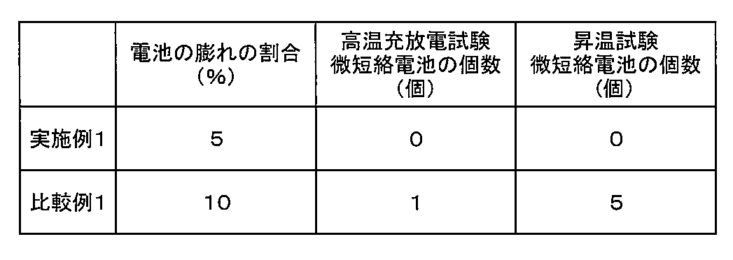
表1に示す通り、前記一般式(1)で表される基を分子内に有するリン酸化合物を含有する非水電解液を用い、かつ熱分解温度が200℃以上のポリイミドにより構成された多孔質フィルムからなるセパレータを有する実施例1の非水電解液二次電池は、通常の非水電解液二次電池に汎用されているポリエチレン製の多孔質フィルムからなるセパレータを用いた比較例1の電池に比べて、高温貯蔵後の膨れの割合が小さかった。また、比較例1の電池では、高温充放電試験時および昇温試験時に微短絡を起こすものが生じたのに対し、実施例1の電池では、いずれの試験時にも微短絡を起こしたものがなかった。
本発明は、その趣旨を逸脱しない範囲で、前記以外の形態としても実施が可能である。本出願に開示された実施形態は一例であって、本発明は、これらの実施形態には限定されない。本発明の範囲は、前記の明細書の記載よりも、添付されている請求の範囲の記載を優先して解釈され、請求の範囲と均等の範囲内での全ての変更は、請求の範囲に含まれる。
本発明の非水電解液二次電池は、高温環境下での使用が可能であり、高温で長時間保持された場合にも優れた信頼性を維持できるものであることから、こうした特性を生かして、例えば車両緊急通報システムの電源用途のように、高温環境下に置かれた後にも良好に放電できることが求められる用途に好ましく適用することができる。
1 正極
2 負極
3 セパレータ
4 電池容器
6 扁平状の巻回電極体
9 封口用蓋体
2 負極
3 セパレータ
4 電池容器
6 扁平状の巻回電極体
9 封口用蓋体
Claims (5)
- 負極、正極、セパレータおよび非水電解液を有する非水電解液二次電池であって、
前記負極は、LiまたはLi合金を含有しており、
前記セパレータとして、融点または熱分解温度が200℃以上である樹脂により構成された多孔質フィルムを有しており、
前記非水電解液は、下記一般式(1)で表される基を分子内に有するリン酸化合物またはホウ酸化合物を含有していることを特徴とする非水電解液二次電池。

- 前記リン酸化合物またはホウ酸化合物の非水電解液中での含有量が、8質量%以下である請求項1に記載の非水電解液二次電池。
- 前記多孔質フィルムを構成する樹脂が、ポリイミドまたはアラミドである請求項1または2に記載の非水電解液二次電池。
- 前記非水電解液は、プロピレンカーボネートを全溶媒中で10体積%以上含有する請求項1~3のいずれかに記載の非水電解液二次電池。
- 前記非水電解液は、LiBF4、LiCF3SO3、Li2C2F4(SO3)2、LiClO4、LiN(FSO2)2、LiN(CF3SO2)2、LiC(CF3SO2)3およびLiCF3CO2より選択される少なくとも1種のリチウム塩を含有する請求項1~4のいずれかに記載の非水電解液二次電池。
Priority Applications (1)
| Application Number | Priority Date | Filing Date | Title |
|---|---|---|---|
| JP2017516968A JPWO2018123085A1 (ja) | 2016-12-26 | 2017-03-09 | 非水電解液二次電池 |
Applications Claiming Priority (2)
| Application Number | Priority Date | Filing Date | Title |
|---|---|---|---|
| JP2016250864 | 2016-12-26 | ||
| JP2016-250864 | 2016-12-26 |
Publications (1)
| Publication Number | Publication Date |
|---|---|
| WO2018123085A1 true WO2018123085A1 (ja) | 2018-07-05 |
Family
ID=62710979
Family Applications (1)
| Application Number | Title | Priority Date | Filing Date |
|---|---|---|---|
| PCT/JP2017/009360 WO2018123085A1 (ja) | 2016-12-26 | 2017-03-09 | 非水電解液二次電池 |
Country Status (2)
| Country | Link |
|---|---|
| JP (1) | JPWO2018123085A1 (ja) |
| WO (1) | WO2018123085A1 (ja) |
Cited By (2)
| Publication number | Priority date | Publication date | Assignee | Title |
|---|---|---|---|---|
| JP2020149763A (ja) * | 2019-03-11 | 2020-09-17 | マクセルホールディングス株式会社 | 非水電解液電池 |
| WO2020246520A1 (ja) * | 2019-06-05 | 2020-12-10 | セントラル硝子株式会社 | 非水電解液 |
Citations (4)
| Publication number | Priority date | Publication date | Assignee | Title |
|---|---|---|---|---|
| JP2007123097A (ja) * | 2005-10-28 | 2007-05-17 | Sony Corp | 電池 |
| JP2007173113A (ja) * | 2005-12-22 | 2007-07-05 | Gs Yuasa Corporation:Kk | 非水電解質二次電池 |
| JP2014137996A (ja) * | 2013-01-16 | 2014-07-28 | Samsung Sdi Co Ltd | リチウム電池 |
| JP2014240189A (ja) * | 2013-05-16 | 2014-12-25 | 東レ株式会社 | 芳香族ポリアミド/芳香族ポリイミド複合多孔質膜および非水電解液系二次電池用セパレータならびに非水電解液系二次電池 |
-
2017
- 2017-03-09 JP JP2017516968A patent/JPWO2018123085A1/ja active Pending
- 2017-03-09 WO PCT/JP2017/009360 patent/WO2018123085A1/ja active Application Filing
Patent Citations (4)
| Publication number | Priority date | Publication date | Assignee | Title |
|---|---|---|---|---|
| JP2007123097A (ja) * | 2005-10-28 | 2007-05-17 | Sony Corp | 電池 |
| JP2007173113A (ja) * | 2005-12-22 | 2007-07-05 | Gs Yuasa Corporation:Kk | 非水電解質二次電池 |
| JP2014137996A (ja) * | 2013-01-16 | 2014-07-28 | Samsung Sdi Co Ltd | リチウム電池 |
| JP2014240189A (ja) * | 2013-05-16 | 2014-12-25 | 東レ株式会社 | 芳香族ポリアミド/芳香族ポリイミド複合多孔質膜および非水電解液系二次電池用セパレータならびに非水電解液系二次電池 |
Cited By (3)
| Publication number | Priority date | Publication date | Assignee | Title |
|---|---|---|---|---|
| JP2020149763A (ja) * | 2019-03-11 | 2020-09-17 | マクセルホールディングス株式会社 | 非水電解液電池 |
| JP7337515B2 (ja) | 2019-03-11 | 2023-09-04 | マクセル株式会社 | 非水電解液電池 |
| WO2020246520A1 (ja) * | 2019-06-05 | 2020-12-10 | セントラル硝子株式会社 | 非水電解液 |
Also Published As
| Publication number | Publication date |
|---|---|
| JPWO2018123085A1 (ja) | 2019-10-31 |
Similar Documents
| Publication | Publication Date | Title |
|---|---|---|
| TWI663763B (zh) | Non-aqueous electrolyte | |
| JP6775500B2 (ja) | 非水電解質電池およびその製造方法 | |
| JP5016814B2 (ja) | 非水系二次電池 | |
| JP6521883B2 (ja) | 非水電解液電池、およびその製造方法 | |
| US8940439B2 (en) | Secondary battery, electronic device, electric power tool, electrical vehicle, and electric power storage system | |
| WO2013005521A1 (ja) | 二次電池 | |
| WO2017154592A1 (ja) | 非水電解液電池 | |
| JP2017195028A (ja) | 非水電解液電池およびその製造方法 | |
| US10833364B2 (en) | Lithium-ion secondary battery | |
| WO2018123085A1 (ja) | 非水電解液二次電池 | |
| JPWO2018212027A1 (ja) | リチウムイオン二次電池用電解液及びこれを用いたリチウムイオン二次電池 | |
| WO2018116491A1 (ja) | 非水電解液二次電池およびその製造方法 | |
| JP2004055154A (ja) | 積層型電池の密封構造および密封処理方法 | |
| US20180159105A1 (en) | Lithium-ion battery | |
| JP2018113164A (ja) | 非水電解液電池およびその製造方法 | |
| JP6973621B2 (ja) | リチウムイオン二次電池 | |
| JP6796477B2 (ja) | 非水電解液電池の製造方法 | |
| WO2019102883A1 (ja) | 非水電解質電池 | |
| JP2019220380A (ja) | 非水電解液電池の製造方法 | |
| JP7112265B2 (ja) | 非水電解液二次電池およびその製造方法 | |
| JP2019040682A (ja) | 非水系電解液及び非水系二次電池 | |
| JP2018106983A (ja) | 非水電解液電池およびその製造方法 | |
| JP2017073334A (ja) | 非水電解液電池 | |
| JP2019220381A (ja) | 非水電解液電池 | |
| JP2016105373A (ja) | 非水電解質二次電池 |
Legal Events
| Date | Code | Title | Description |
|---|---|---|---|
| ENP | Entry into the national phase |
Ref document number: 2017516968 Country of ref document: JP Kind code of ref document: A |
|
| 121 | Ep: the epo has been informed by wipo that ep was designated in this application |
Ref document number: 17887721 Country of ref document: EP Kind code of ref document: A1 |
|
| NENP | Non-entry into the national phase |
Ref country code: DE |
|
| 122 | Ep: pct application non-entry in european phase |
Ref document number: 17887721 Country of ref document: EP Kind code of ref document: A1 |