WO2018116760A1 - 端面切削加工装置及び端面切削加工方法 - Google Patents
端面切削加工装置及び端面切削加工方法 Download PDFInfo
- Publication number
- WO2018116760A1 WO2018116760A1 PCT/JP2017/042602 JP2017042602W WO2018116760A1 WO 2018116760 A1 WO2018116760 A1 WO 2018116760A1 JP 2017042602 W JP2017042602 W JP 2017042602W WO 2018116760 A1 WO2018116760 A1 WO 2018116760A1
- Authority
- WO
- WIPO (PCT)
- Prior art keywords
- cutting
- face
- rotating body
- end surface
- rotating
- Prior art date
- Legal status (The legal status is an assumption and is not a legal conclusion. Google has not performed a legal analysis and makes no representation as to the accuracy of the status listed.)
- Ceased
Links
Images


Classifications
-
- B—PERFORMING OPERATIONS; TRANSPORTING
- B23—MACHINE TOOLS; METAL-WORKING NOT OTHERWISE PROVIDED FOR
- B23C—MILLING
- B23C3/00—Milling particular work; Special milling operations; Machines therefor
-
- B—PERFORMING OPERATIONS; TRANSPORTING
- B23—MACHINE TOOLS; METAL-WORKING NOT OTHERWISE PROVIDED FOR
- B23C—MILLING
- B23C5/00—Milling-cutters
- B23C5/02—Milling-cutters characterised by the shape of the cutter
- B23C5/06—Face-milling cutters, i.e. having only or primarily a substantially flat cutting surface
-
- B—PERFORMING OPERATIONS; TRANSPORTING
- B26—HAND CUTTING TOOLS; CUTTING; SEVERING
- B26D—CUTTING; DETAILS COMMON TO MACHINES FOR PERFORATING, PUNCHING, CUTTING-OUT, STAMPING-OUT OR SEVERING
- B26D1/00—Cutting through work characterised by the nature or movement of the cutting member or particular materials not otherwise provided for; Apparatus or machines therefor; Cutting members therefor
- B26D1/01—Cutting through work characterised by the nature or movement of the cutting member or particular materials not otherwise provided for; Apparatus or machines therefor; Cutting members therefor involving a cutting member which does not travel with the work
- B26D1/12—Cutting through work characterised by the nature or movement of the cutting member or particular materials not otherwise provided for; Apparatus or machines therefor; Cutting members therefor involving a cutting member which does not travel with the work having a cutting member moving about an axis
- B26D1/25—Cutting through work characterised by the nature or movement of the cutting member or particular materials not otherwise provided for; Apparatus or machines therefor; Cutting members therefor involving a cutting member which does not travel with the work having a cutting member moving about an axis with a non-circular cutting member
- B26D1/26—Cutting through work characterised by the nature or movement of the cutting member or particular materials not otherwise provided for; Apparatus or machines therefor; Cutting members therefor involving a cutting member which does not travel with the work having a cutting member moving about an axis with a non-circular cutting member moving about an axis substantially perpendicular to the line of cut
- B26D1/28—Cutting through work characterised by the nature or movement of the cutting member or particular materials not otherwise provided for; Apparatus or machines therefor; Cutting members therefor involving a cutting member which does not travel with the work having a cutting member moving about an axis with a non-circular cutting member moving about an axis substantially perpendicular to the line of cut and rotating continuously in one direction during cutting
- B26D1/29—Cutting through work characterised by the nature or movement of the cutting member or particular materials not otherwise provided for; Apparatus or machines therefor; Cutting members therefor involving a cutting member which does not travel with the work having a cutting member moving about an axis with a non-circular cutting member moving about an axis substantially perpendicular to the line of cut and rotating continuously in one direction during cutting with cutting member mounted in the plane of a rotating disc, e.g. for slicing beans
-
- B—PERFORMING OPERATIONS; TRANSPORTING
- B26—HAND CUTTING TOOLS; CUTTING; SEVERING
- B26D—CUTTING; DETAILS COMMON TO MACHINES FOR PERFORATING, PUNCHING, CUTTING-OUT, STAMPING-OUT OR SEVERING
- B26D3/00—Cutting work characterised by the nature of the cut made; Apparatus therefor
Definitions
- the present invention relates to an end face cutting apparatus and an end face cutting method.
- a sheet such as a polarizing plate is formed by cutting a sheet-like sheet into a predetermined shape and size one by one with a rotary blade having a blade portion on the outer periphery, and is used for various applications.
- the end face of the sheet formed by such cutting is rough due to the occurrence of crusting or the adhesive sticking out, so the end face of the sheet is cut to remove these. End face cutting devices have been proposed.
- a rotating body portion that has a rotating shaft and rotates around the rotating shaft, and a cutting portion that is fixed to one surface of the rotating body portion and that cuts the end surface of the laminated body in which sheets are stacked.
- the cutting part has a fixed part fixed to the rotating body part, and a cutting blade part protruding from the fixed part toward the end surface of the laminate, and the cutting blade part is the rotating body part.
- an end face cutting apparatus having a cutting edge for cutting the end face at an end portion on the downstream side in the rotation direction (see Patent Document 1).
- the cutting edge is formed along a direction orthogonal to the side surface portion of the cutting blade portion, and the downstream side in the rotation direction of the cutting portion (that is, the cutting blade portion) is positioned on the rotating shaft side.
- the cutting edge is inclined to the downstream side in the rotation direction with respect to a virtual straight line passing through the rotating shaft and the end of the cutting edge on the rotating shaft side.
- the cutting edge of the laminated sheets is suppressed while suppressing the cracks (cracks) and delaminations (peeling) of the sheets by tilting the cutting edge with respect to the virtual straight line toward the downstream side in the rotation method direction.
- the end face can be subjected to end face cutting.
- an object of the present invention is to provide an end face cutting apparatus and an end face cutting method capable of suppressing the consumption of a cutting portion.
- An end face cutting apparatus for cutting an end face of a laminate formed by laminating sheets, A rotating body portion having a rotating shaft and rotating about the rotating shaft center; A cutting portion that is disposed on one surface of the rotating body portion and cuts the end surface; The cutting portion has a cutting blade portion protruding from the rotating body portion toward the end surface, The cutting blade portion has a cutting edge for cutting the end face at an end portion on the downstream side in the rotation direction of the rotating body portion, The cutting edge is configured to be inclined to the upstream side in the rotation direction with respect to a virtual straight line that is orthogonal to the rotation axis and passes through the end of the cutting edge on the rotation axis side.
- the angle at which the cutting edge is inclined with respect to the virtual straight line is preferably 5 to 40 °.
- the end face cutting method according to the present invention is: An end face cutting method for cutting an end face of a laminate formed by laminating sheets, Using the end face cutting device, the end face is cut by the cutting edge of the rotating cutting part while rotating the cutting part by rotating the rotating body part about the rotation axis. Is the method.
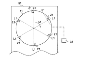
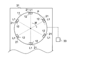
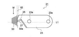
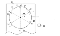
- FIG. 1 is a schematic plan view of the periphery of the rotating body portion and the cutting blade portion of the end face cutting apparatus of FIG. 1 viewed from the right side of FIG.
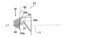
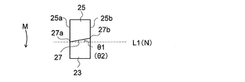
- the schematic front view which shows the cutting blade part with which the end surface cutting apparatus of FIG. 2 was equipped
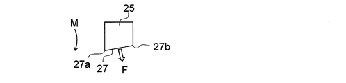
- the schematic side view which looked at the state which the cutting-blade part of FIG. 3 is cutting the end surface of a laminated body (sheet
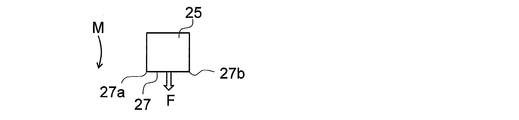
- the schematic plan view which shows the direction of the force applied to the end surface of a laminated body (sheet
- the schematic plan view which shows the rotary body part and cutting blade part periphery of the end surface cutting apparatus of another aspect of this embodiment.
- the schematic front view which shows the cutting blade part with which the end surface cutting apparatus of FIG. 6 was equipped.
- Schematic side view of the cutting blade part of FIG. 7 viewed from the right side of FIG.
- arranged to the rotary body part The schematic plan view which shows the direction of the force applied to the end surface of a laminated body (sheet
- the end surface cutting apparatus 1 of the present embodiment is An end face cutting apparatus 1 for cutting an end face 60a of a laminate 60 in which sheets 50 are laminated (that is, an end face 50a of the laminated sheets 50), A rotating body 11 having a rotation axis R and rotating about the rotation axis R; A cutting portion 21 disposed on one surface 11a of the rotating body portion 11 and cutting the end surface 60a (end surface 50a);
- the cutting part 21 has a cutting blade part 25 protruding from the rotating body part 11 toward the end face 60 (end face 50a),
- the cutting blade portion 25 has a cutting edge 27 for cutting the end surface 60a (end surface 50a) at an end portion on the downstream side in the rotation direction M of the rotating body portion 11;
- the cutting edge 27 is configured to be inclined to the upstream side in the rotation direction M with respect to a virtual straight line L1 that is orthogonal to the rotation axis R and passes through the end 27a of the cutting edge 27 on the rotation axis R side.
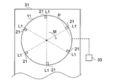
- the end surface cutting apparatus 1 is capable of rotating the rotating body 11, and the supporting section 31 is movable so that the supporting cutting section 21 cuts the entire end surface 60a (end surface 50a), and the rotating body.
- a drive unit 33 that rotates the unit 11 and a holding unit 35 that holds the stacked body 60 (the stacked sheets 50) from the lowermost surface side and the uppermost surface side are further provided.
- the upstream side of the rotational direction M means the rear side of the rotational direction M (the side opposite to the traveling direction), and the downstream side of the rotational direction M means the front side (the traveling side) of the rotational direction M.
- seat 50 is not specifically limited, For example, a polarizing plate is mentioned. As this polarizing plate, what laminated
- the shape of the sheet 50 is, for example, a rectangular shape.
- the number of sheets 50 to be laminated is not particularly limited.
- the rotating body portion 11 applies cutting force to the cutting edge 27 of the cutting blade portion 25 of the cutting portion 21 by rotating.
- the shape, material, size, etc. of the rotating body 11 are not particularly limited.
- the shape of the rotating body portion 11 is a disk shape, and the rotating body portion 11 is formed of a metal material such as stainless steel.
- size of the rotary body part 11 can be suitably set according to the quantity etc. of the sheet
- the rotating body portion 11 is configured to be movable in the direction of the rotation axis R and the direction perpendicular to the rotation axis R as the support portion 31 moves.
- the rotating body portion 11 is rotatably supported on a support shaft 32 disposed on the support portion 31.
- the quantity of the rotating body part 11 is not specifically limited. Even if one rotating body portion 11 is provided so that one end face 60a of the laminated body 60 (one end face 50a of the laminated sheets 50) can be cut, two end faces 60a (two end faces) facing each other are provided. Two may be provided so that 50a) can be cut at once.
- the rotational speed of the rotating body portion 11 is not particularly limited, but may be, for example, 1000 to 6000 rpm.
- the cutting part 21 is arranged on one surface 11a of the rotating body part 11 and cuts the end face 60 (end face 50a).
- 1 and 2 show a mode in which six cutting parts 21 are arranged on the rotating body part 11, the number of cutting parts 21 arranged on the rotating body part 11 is not particularly limited.
- the cutting part 21 has the cutting blade part 25 which protrudes from the rotating body part 11 toward the end surface 60a (end surface 50a) from the rotating body part 11.
- the cutting blade part 25 cuts the end surface 60a of the laminated body 60 (end surface 50a of the laminated
- the cutting blade portion 25 protrudes from the rotating body portion 11 toward the end surface 50 a, and has a cutting edge 27 at an end portion on the downstream side in the rotation direction M of the rotating body portion 11. In the aspect shown in FIG. 2, the cutting blade part 25 protrudes directly from the rotary body part 11 toward the end surface 50a.
- the cutting blade portion 25 is formed in a rectangular shape when viewed along the extending direction of the rotation axis R, and has a side surface portion 25a on the rotation axis R side and a side surface portion 25b on the side away from the rotation axis R. is doing.
- the cutting blade portion 25 is disposed on one surface 11a of the rotating body portion 11 along the direction P perpendicular to the virtual straight line L1.
- the imaginary straight line L1 is on the one surface 11a of the rotating body portion 11 (and parallel to the one surface 11a of the rotating body portion 11) and the end of the rotation axis R and the cutting edge 27 on the rotation axis R side. This is a virtual straight line passing through the portion 27a.
- the blade edge 27 is formed so as to cut the end surface 60a of the laminated body 60 (the end surface 50a of the laminated sheets 50).
- the cutting edge 27 is inclined with respect to a direction N orthogonal to the side surface portion 25 a of the cutting blade portion 25.
- the blade edge 27 is inclined to the upstream side in the rotation direction M with respect to the virtual straight line L1 in a state of being arranged in the rotating body portion 11 (opposite to the rotation axis R than the end portion 27a on the rotation axis R side).
- the end portion 27b on the other side is inclined so as to be located on the upstream side in the rotation direction M).
- the angle ⁇ 1 formed by the cutting edge 27 with respect to the virtual straight line L1 is not particularly limited, but is preferably 5 to 40 °, more preferably 5 to 25 °.
- the angle is 5 ° or more, the stress received from the stacked body 60 (the stacked sheets 50) can be sufficiently reduced, so that the wear of the cutting edge 27 can be suppressed.
- the inclination angle is too large, the cutting force toward the end face direction of the laminate 60 (laminated sheet 50) becomes too large than the force toward the direction perpendicular to the end face direction. There is a possibility that the sheet 50 is displaced. If an attempt is made to hold the laminate 60 (laminated sheets 50) strongly in order to suppress this deviation, the sheets 50 may be damaged.
- the angle is 40 ° or less, the stacked sheets 50 can be prevented from shifting, and therefore, end face cutting can be performed more sufficiently.
- the material of the cutting blade part 25 is not specifically limited. Examples of the material include carbon steel (S45C).
- the material of the blade edge 27 is not particularly limited as long as the end surface 60a (end surface 50a) can be cut.
- the cutting edge 27 may have a diamond crystal layer laminated on the surface of carbon steel (S45C). Examples of the particle diameter of such diamond particles include 5 to 50 ⁇ m.
- the shape of the blade edge 27 is not particularly limited.
- the cutting edge 27 may be linear or curved so as to protrude toward the downstream side in the rotation direction when viewed along the extending direction of the rotation axis R.
- the radius of curvature is preferably 1 to 50% with respect to the distance connecting the rotation axis R and the end 27a of the cutting edge 27 on the rotation axis R side in the shortest distance.
- the cutting blade portion 25 has inclined portions 26a and 26b that are inclined in a direction away from the end surface 60a (end surface 50a) from the cutting edge 27 toward the end opposite to the cutting edge 27. . Since the cutting blade portion 25 has the inclined portions 26a and 26b, the cutting blade portion 25 can be further suppressed from coming into contact with the uncut region of the end surface 60a (end surface 50a).
- the inclination angle of the inclined portion 26a closest to the cutting edge 27 is, for example, 0 ° And 15 ° or less (0 ° ⁇ 2 ⁇ 15 °).
- the inclination angle of the inclined portion 26b (the second front relief angle and the angle formed with respect to the virtual plane including the rotation direction M) can be set as appropriate. Further, the inclination angle (rake angle) of the cutting edge 27 with respect to the virtual plane including the rotation direction M can be set to be more than 0 ° and 20 ° or less (0 ° ⁇ rake angle ⁇ 20 °). In the present invention, a mode in which the cutting blade portion 25 does not have the inclined portions 26a and 26b may be employed.
- the cutting edge 27 when the cutting edge 27 is arranged along the imaginary straight line L1 as in the conventional end face cutting apparatus shown in FIG. 9, as shown in FIG. 10, it is perpendicular to the end face direction of the sheet 50.
- the cutting force F is applied from the cutting edge 27 in a proper direction (stacking direction).
- the cutting force is uniformly applied to the laminated body 60 (the laminated sheets 50) from the blade edge 27.
- the cutting force is uniformly applied to the laminated body 60 (laminated sheets 50) from the blade edge 27 in the direction in which the sheets 50 are separated from each other, there is a possibility that cracks and delamination may occur in the sheet 50.
- the cutting edge 27 is inclined to the upstream side in the rotation direction M with respect to the virtual straight line L1, so that the cutting edge 27 rotates on the stacked sheets 50 as shown in FIG.
- a cutting force is applied in the direction from the end portion 27a on the axis R side to the end portion 27b on the side opposite to the rotation axis R in the direction of pulling the stacked body 60 (the stacked sheets 50).
- the cutting force (pushing force) applied from the blade edge 27 to the laminated body 60 (laminated sheet 50) is smaller than when the blade edge 27 is inclined downstream with respect to the virtual straight line L1, Accordingly, the stress (load) received by the blade edge 27 from the laminated body 60 (laminated sheet 50) is reduced, so that consumption is reduced. Therefore, according to the cutting part 21 of this embodiment, it can suppress that a crack and delamination generate
- the support portion 31 is configured to be movable in a direction parallel to a plane including the rotation direction of the rotating body portion 11 and in a direction perpendicular to the plane. For example, it is moved by a conventionally known moving device. By moving the support portion 31 in the vertical direction, the cutting depth with respect to the end surface 60a (end surface 50a) of the cutting edge 27 is adjusted, and by moving in the parallel direction, the end surface 60a ( The entire end surface 50a) is cut from one end to the other end.
- the drive unit 33 rotates the rotating body unit 11.
- An example of the drive unit 33 is a motor.
- the holding unit 35 holds the laminated body 60 (laminated sheets 50) sandwiched from the lowermost surface side and the uppermost surface side.
- the holding unit 35 includes a first portion 35a that comes into contact with the uppermost surface of the laminate 60 (the laminated sheets 50) and a second portion 35b that comes into contact with the lowermost surface.
- the laminated body 60 (laminated sheet 50) is held by being sandwiched between the portions 35a and 35b.
- the holding unit 35 rotates around a virtual straight line L2 connecting the center of the lowermost surface and the center of the uppermost surface of the laminated body 60 (laminated sheet 50).
- the end surface 60a (end surface 50a) of the end surface of the sheet 50) can be changed.
- the cutting blade portion 25 is formed integrally with the rotating body portion 11, but may be formed separately from the rotating body portion 11.
- the cutting part 21 further includes a fixing part 23 that fixes the cutting blade part 25 to the rotating body part 11, and the aspect in which the cutting blade part 25 is fixed to the rotating body part 11 via the fixing part 23 is also adopted.
- the cutting blade portion 25 protrudes from the fixed portion 23 toward the end surface 60a (end surface 50a). That is, the cutting blade part 25 protrudes toward the end surface 60a (end surface 50a) from the rotating body part 11 via the fixed part 23 (indirectly).
- the rotating body portion 11 has a recess 12 that is recessed from the outer peripheral edge of the rotating body portion 11 so that the cutting portion 21 fits snugly.
- the cutting part 21 has a fixing part 23 fixed to the rotating body part 11 and a cutting blade part 25 protruding from the fixing part 23 toward the end face 60a (end face 50a).
- the fixing portion 23 is orthogonal to the rotation axis R and extends along a direction P perpendicular to an imaginary straight line L1 passing through the end portion 27a of the cutting edge 27 on the rotation axis R side.
- the fixed portion 23 is formed in a rectangular shape when viewed along the extending direction of the rotation axis R.
- the fixing portion 23 is fitted into and fixed to the concave portion 12 formed in the rotating body portion 11.
- the rotating body portion 11 is configured to be fitted into a recess 12 formed so as to be recessed inward from the outer periphery, and fixed by a fixing member 23 a such as a screw.
- the cutting blade portion 25 protrudes from the fixed portion 23 to the side opposite to the rotating body portion 11 and has a cutting edge 27 at the tip portion.
- the cutting blade portion 25 has a blade edge 27 at an end portion on the downstream side in the rotation direction M of the rotating body portion 11.
- the cutting blade portion 25 is formed in a rectangular shape when viewed along the extending direction of the rotation axis R, and has a side surface portion 25a on the rotation axis R side and a side surface portion 25b on the side away from the rotation axis R. is doing.
- the cutting edge 27 is inclined with respect to a direction N orthogonal to the side surface portion 25 a of the cutting blade portion 25.
- the cutting blade portion 25 may be formed integrally with the fixed portion 23 or may be formed separately from the fixed portion 23.
- the material of the fixing part 23 is not particularly limited. As the material thereof, for example, the same material as that of the cutting blade portion 25 is used.
- the arrangement of the cutting blade portion 25 (that is, the cutting portion 21) in the rotating body portion 11 is such that the cutting edge 27 is inclined as described above with respect to the side surface portion 25a and the cutting portion 21 is fixed to the fixing portion 23.
- the cutting edge 27 is inclined upstream in the rotational direction M with respect to the imaginary straight line L1 (the end 27a on the rotational axis R side is more rotational than the end 27b on the opposite side of the rotational axis R). If it inclines so that it may be located in the downstream of M), it will not specifically limit.
- the cutting part 21 may be arranged along the direction P perpendicular to the virtual straight line L ⁇ b> 1 on the one surface 11 a of the rotating body part 11.
- the upstream end in the rotational direction M is closer to the rotational axis R side than the downstream end.
- the end on the downstream side in the rotation direction M with respect to the direction P perpendicular to the virtual straight line L1 may be inclined so as to be farther from the rotation axis R side than the end on the upstream side.
- the end surface cutting apparatus 1 of the present embodiment When the rotating body 11 is rotated by the drive unit 33 while the support 31 is moved, the end surface 60a (the end surface of the stacked sheets 50) facing the rotating body 11 of the stacked body 60 (the stacked sheets 50). 50a) is cut by the cutting edge 27 of the cutting blade portion 25 of the cutting portion 21 from one end to the other end.
- the end surface cutting apparatus 1 of the present embodiment is An end face cutting apparatus 1 for cutting an end face 60a of a laminate 60 in which sheets 50 are laminated (an end face 50a of the laminated sheets 50), A rotating body 11 having a rotation axis R and rotating about the rotation axis R; A cutting part 21 disposed on one surface 11a of the rotating body part 11 and cutting the end face 50a; The cutting part 21 has a cutting blade part 25 protruding from the rotating body part 11 toward the end face 60a (end face 50a), The cutting blade portion 25 has a cutting edge 27 that cuts the end surface 50a at an end portion on the downstream side in the rotation direction M of the rotating body portion 11; The cutting edge 27 is configured to be inclined to the upstream side in the rotation direction M with respect to a virtual straight line L1 that is orthogonal to the rotation axis R and passes through the end 27a of the cutting edge 27 on the rotation axis R side. ing.
- the blade edge 27 is inclined toward the upstream side in the rotational direction M with respect to the virtual straight line L1, whereby the blade edge when cutting the end surface 60a (end surface 50a). Since the load applied to the blade 27 can be reduced, consumption of the blade edge 27 can be suppressed.
- the angle at which the blade edge 27 is inclined with respect to the virtual straight line L1 is preferably 5 to 40 °. When the angle is 5 ° or more, consumption of the cutting edge 27 can be sufficiently suppressed. On the other hand, if the inclination is too large, the cutting force directed in the extending direction of the end surface 60a (end surface 50a) of the laminate 60 (laminated sheet 50) is directed in the direction perpendicular to the extending direction of the end surface. And the stacked sheets 50 are displaced from each other. As a result, the sheet 50 deviating from a desired dimension may be formed.
- the sheet 50 may be damaged. However, since the sheet 50 can be prevented from shifting when the angle is 40 ° or less, the end face cutting can be performed more sufficiently.
- the end face cutting method of this embodiment is An end face cutting method for cutting an end face 60a (end face 50a of a laminated sheet 50) of a laminate 60 in which sheets 50 are laminated,
- the cutting edge 21 of the cutting part 21 that rotates while rotating the cutting part 21 by rotating the rotating body part 11 about the rotation axis R using the end face cutting device 1,
- This is a method of cutting the end face 60a (end face 50a).
- the end face cutting apparatus 1 and the end face cutting method capable of suppressing the consumption of the cutting portion 21 are provided.
- Example 1 As the sheet 50, a protective film is laminated on both sides of the polarizer via an adhesive layer, a surface protective film is laminated on one protective film via an adhesive layer, and an adhesive layer is interposed on the other protective film.
- a polarizing plate surface protective film / adhesive layer / protective film / adhesive layer / polarizer / adhesive layer / protective film / adhesive layer / separator formed by laminating a separator was used.
- the end face cutting apparatus 1 shown in FIG. 1 only one cutting part 21 is arranged on the rotating body part 11, 200 sheets 50 are laminated to form a laminated body 60, and the laminated body 60 is held by a holding part.
- the inclination angle ⁇ 1 with respect to the virtual straight line L1 of the cutting edge 27 held at 35 and inclined to the upstream side in the rotation direction M with respect to the virtual straight line L1 is changed as shown in Table 1, and the end face 60a (end face 50a) is changed.
- the cutting process was performed.
- the diameter of the rotating body 11 was 180 mm, the number of cutting parts 21 was three, and the following conditions were set.
- Clamping pressure of holding part 0.2MPa -Clamp height (corresponding to the thickness (height) of the laminate of sheets): 80 mm -Moving speed of the support part 31: 600 mm / min ⁇
- Rotating speed of the rotating body 11 6000 rpm
- Cutting position The cutting position was set so that the center of the rotating body portion 11 was positioned at the center of the laminated body 60 of the sheet 50.
- -Arrangement of the laminated body 60 of the sheet 50 The arrangement of the laminated body 60 of the sheet 50 was set so that the separator side was positioned upward.
- Example 2 In the same manner as in Example 1, the end face cutting of the laminate 60 of 200 sheets 50 was performed 5 times, and it was examined whether or not it was within a desired processing accuracy range. ⁇ 0.05 mm was adopted as the range of processing accuracy. Of the five times, the number of times (success times) within the range of the desired processing accuracy was examined. Specifically, in one end (200 sheets) end face processing, when all 200 sheets were within the range of the desired processing accuracy, it was considered successful. That is, if one of the 200 sheets is out of the range of the desired processing accuracy, it is determined as a failure. The results are shown in Table 2.
Landscapes
- Engineering & Computer Science (AREA)
- Mechanical Engineering (AREA)
- Life Sciences & Earth Sciences (AREA)
- Forests & Forestry (AREA)
- Milling Processes (AREA)
- Nonmetal Cutting Devices (AREA)
Priority Applications (2)
| Application Number | Priority Date | Filing Date | Title |
|---|---|---|---|
| KR1020187034593A KR102019137B1 (ko) | 2016-12-22 | 2017-11-28 | 단면 절삭 가공 장치 및 단면 절삭 가공 방법 |
| CN201780031584.0A CN109311176B (zh) | 2016-12-22 | 2017-11-28 | 端面切削加工装置及端面切削加工方法 |
Applications Claiming Priority (2)
| Application Number | Priority Date | Filing Date | Title |
|---|---|---|---|
| JP2016249771A JP6482522B2 (ja) | 2016-12-22 | 2016-12-22 | 端面切削加工装置及び端面切削加工方法 |
| JP2016-249771 | 2016-12-22 |
Publications (1)
| Publication Number | Publication Date |
|---|---|
| WO2018116760A1 true WO2018116760A1 (ja) | 2018-06-28 |
Family
ID=62627323
Family Applications (1)
| Application Number | Title | Priority Date | Filing Date |
|---|---|---|---|
| PCT/JP2017/042602 Ceased WO2018116760A1 (ja) | 2016-12-22 | 2017-11-28 | 端面切削加工装置及び端面切削加工方法 |
Country Status (5)
| Country | Link |
|---|---|
| JP (1) | JP6482522B2 (enExample) |
| KR (1) | KR102019137B1 (enExample) |
| CN (1) | CN109311176B (enExample) |
| TW (1) | TWI674161B (enExample) |
| WO (1) | WO2018116760A1 (enExample) |
Citations (4)
| Publication number | Priority date | Publication date | Assignee | Title |
|---|---|---|---|---|
| JPS5924909A (ja) * | 1982-06-02 | 1984-02-08 | ジエイ・ピイ・ツ−ル・リミテツド | 正面フライスカツタ− |
| JP2002059308A (ja) * | 2000-08-21 | 2002-02-26 | Tadashi Sugiyama | フライスカッター |
| JP2008260077A (ja) * | 2007-04-10 | 2008-10-30 | Nakao Technica Kk | 切削加工機用旋回同期装置及び切削加工機 |
| JP2011093086A (ja) * | 2009-09-30 | 2011-05-12 | Sumitomo Chemical Co Ltd | フィルムの端面加工用カッターおよびこれを備える加工機、並びに、フィルムの端面加工方法 |
Family Cites Families (7)
| Publication number | Priority date | Publication date | Assignee | Title |
|---|---|---|---|---|
| JPS5354490U (enExample) * | 1976-10-13 | 1978-05-10 | ||
| JP2547925Y2 (ja) * | 1991-05-31 | 1997-09-17 | 東芝タンガロイ株式会社 | スローアウェイカッタ |
| JP3619813B2 (ja) * | 2002-02-08 | 2005-02-16 | 三和研磨工業株式会社 | 回転工具 |
| DE102009012433A1 (de) * | 2009-03-10 | 2010-09-16 | Kennametal Inc. | Zerspanungswerkzeug für eine Werkzeugmaschine |
| SE534649C2 (sv) * | 2009-12-18 | 2011-11-08 | Sandvik Intellectual Property | Planfräs för finfräsning |
| JP5939687B2 (ja) * | 2013-02-19 | 2016-06-22 | 株式会社ソディック | 切削工具 |
| JP5743291B2 (ja) * | 2013-04-09 | 2015-07-01 | 住友化学株式会社 | 切削加工方法 |
-
2016
- 2016-12-22 JP JP2016249771A patent/JP6482522B2/ja active Active
-
2017
- 2017-11-28 KR KR1020187034593A patent/KR102019137B1/ko active Active
- 2017-11-28 WO PCT/JP2017/042602 patent/WO2018116760A1/ja not_active Ceased
- 2017-11-28 CN CN201780031584.0A patent/CN109311176B/zh active Active
- 2017-12-14 TW TW106143898A patent/TWI674161B/zh active
Patent Citations (4)
| Publication number | Priority date | Publication date | Assignee | Title |
|---|---|---|---|---|
| JPS5924909A (ja) * | 1982-06-02 | 1984-02-08 | ジエイ・ピイ・ツ−ル・リミテツド | 正面フライスカツタ− |
| JP2002059308A (ja) * | 2000-08-21 | 2002-02-26 | Tadashi Sugiyama | フライスカッター |
| JP2008260077A (ja) * | 2007-04-10 | 2008-10-30 | Nakao Technica Kk | 切削加工機用旋回同期装置及び切削加工機 |
| JP2011093086A (ja) * | 2009-09-30 | 2011-05-12 | Sumitomo Chemical Co Ltd | フィルムの端面加工用カッターおよびこれを備える加工機、並びに、フィルムの端面加工方法 |
Also Published As
| Publication number | Publication date |
|---|---|
| KR102019137B1 (ko) | 2019-09-06 |
| TWI674161B (zh) | 2019-10-11 |
| CN109311176B (zh) | 2020-02-14 |
| CN109311176A (zh) | 2019-02-05 |
| KR20190050740A (ko) | 2019-05-13 |
| JP6482522B2 (ja) | 2019-03-13 |
| TW201827146A (zh) | 2018-08-01 |
| JP2018103277A (ja) | 2018-07-05 |
Similar Documents
| Publication | Publication Date | Title |
|---|---|---|
| JP5823677B2 (ja) | フィルムの端面加工用カッターおよびこれを備える加工機、並びに、フィルムの端面加工方法 | |
| CN110461519B (zh) | 经非直线加工的带粘合剂层的光学层叠体的制造方法 | |
| CN101952091B (zh) | 使用旋转圆形刀片的纵切剪机装置以及片材的制造方法 | |
| CN109477932B (zh) | 光学叠层的制造方法 | |
| CN111558741A (zh) | 光学薄膜的制造方法 | |
| JP4662357B2 (ja) | 光学フィルムシートの切断方法、および光学フィルムシートの切断装置 | |
| JP6464136B2 (ja) | 端面切削加工装置及び端面切削加工方法 | |
| JP6482522B2 (ja) | 端面切削加工装置及び端面切削加工方法 | |
| CN116748577B (zh) | 复合切削工具及使用它的树脂片的制造方法 | |
| CN104972487A (zh) | 形成光学膜层积体条带的装置以及方法 | |
| CN113423527B (zh) | 光学薄膜的制造方法 | |
| TWI845603B (zh) | 光學薄膜的製造方法 | |
| US10144075B2 (en) | Flat file | |
| JP2009195995A (ja) | ブレードによる切断方法 | |
| CN118804808A (zh) | 树脂片材的制造方法 | |
| WO2018220959A1 (ja) | 光学積層体の製造方法 | |
| JP2021516626A (ja) | 切削装置およびこれを用いたフィルム積層体の面取方法 | |
| JP2023087193A (ja) | カッター、カッティング装置およびカッティング方法 | |
| JP2015085430A (ja) | スリッティング工具用切断刃およびスリッティング工具 |
Legal Events
| Date | Code | Title | Description |
|---|---|---|---|
| 121 | Ep: the epo has been informed by wipo that ep was designated in this application |
Ref document number: 17883736 Country of ref document: EP Kind code of ref document: A1 |
|
| ENP | Entry into the national phase |
Ref document number: 20187034593 Country of ref document: KR Kind code of ref document: A |
|
| NENP | Non-entry into the national phase |
Ref country code: DE |
|
| 122 | Ep: pct application non-entry in european phase |
Ref document number: 17883736 Country of ref document: EP Kind code of ref document: A1 |