WO2018110167A1 - 動力伝達装置 - Google Patents
動力伝達装置 Download PDFInfo
- Publication number
- WO2018110167A1 WO2018110167A1 PCT/JP2017/040492 JP2017040492W WO2018110167A1 WO 2018110167 A1 WO2018110167 A1 WO 2018110167A1 JP 2017040492 W JP2017040492 W JP 2017040492W WO 2018110167 A1 WO2018110167 A1 WO 2018110167A1
- Authority
- WO
- WIPO (PCT)
- Prior art keywords
- friction surface
- armature
- rotor
- side friction
- power transmission
- Prior art date
- Legal status (The legal status is an assumption and is not a legal conclusion. Google has not performed a legal analysis and makes no representation as to the accuracy of the status listed.)
- Ceased
Links
Images


Classifications
-
- F—MECHANICAL ENGINEERING; LIGHTING; HEATING; WEAPONS; BLASTING
- F16—ENGINEERING ELEMENTS AND UNITS; GENERAL MEASURES FOR PRODUCING AND MAINTAINING EFFECTIVE FUNCTIONING OF MACHINES OR INSTALLATIONS; THERMAL INSULATION IN GENERAL
- F16D—COUPLINGS FOR TRANSMITTING ROTATION; CLUTCHES; BRAKES
- F16D27/00—Magnetically- or electrically- actuated clutches; Control or electric circuits therefor
- F16D27/10—Magnetically- or electrically- actuated clutches; Control or electric circuits therefor with an electromagnet not rotating with a clutching member, i.e. without collecting rings
- F16D27/108—Magnetically- or electrically- actuated clutches; Control or electric circuits therefor with an electromagnet not rotating with a clutching member, i.e. without collecting rings with axially movable clutching members
- F16D27/112—Magnetically- or electrically- actuated clutches; Control or electric circuits therefor with an electromagnet not rotating with a clutching member, i.e. without collecting rings with axially movable clutching members with flat friction surfaces, e.g. discs
-
- H—ELECTRICITY
- H02—GENERATION; CONVERSION OR DISTRIBUTION OF ELECTRIC POWER
- H02K—DYNAMO-ELECTRIC MACHINES
- H02K1/00—Details of the magnetic circuit
- H02K1/06—Details of the magnetic circuit characterised by the shape, form or construction
- H02K1/22—Rotating parts of the magnetic circuit
-
- F—MECHANICAL ENGINEERING; LIGHTING; HEATING; WEAPONS; BLASTING
- F16—ENGINEERING ELEMENTS AND UNITS; GENERAL MEASURES FOR PRODUCING AND MAINTAINING EFFECTIVE FUNCTIONING OF MACHINES OR INSTALLATIONS; THERMAL INSULATION IN GENERAL
- F16D—COUPLINGS FOR TRANSMITTING ROTATION; CLUTCHES; BRAKES
- F16D27/00—Magnetically- or electrically- actuated clutches; Control or electric circuits therefor
- F16D2027/007—Bias of an armature of an electromagnetic clutch by flexing of substantially flat springs, e.g. leaf springs
-
- F—MECHANICAL ENGINEERING; LIGHTING; HEATING; WEAPONS; BLASTING
- F16—ENGINEERING ELEMENTS AND UNITS; GENERAL MEASURES FOR PRODUCING AND MAINTAINING EFFECTIVE FUNCTIONING OF MACHINES OR INSTALLATIONS; THERMAL INSULATION IN GENERAL
- F16D—COUPLINGS FOR TRANSMITTING ROTATION; CLUTCHES; BRAKES
- F16D27/00—Magnetically- or electrically- actuated clutches; Control or electric circuits therefor
- F16D2027/008—Details relating to the magnetic circuit, or to the shape of the clutch parts to achieve a certain magnetic path
-
- F—MECHANICAL ENGINEERING; LIGHTING; HEATING; WEAPONS; BLASTING
- F16—ENGINEERING ELEMENTS AND UNITS; GENERAL MEASURES FOR PRODUCING AND MAINTAINING EFFECTIVE FUNCTIONING OF MACHINES OR INSTALLATIONS; THERMAL INSULATION IN GENERAL
- F16D—COUPLINGS FOR TRANSMITTING ROTATION; CLUTCHES; BRAKES
- F16D27/00—Magnetically- or electrically- actuated clutches; Control or electric circuits therefor
- F16D27/02—Magnetically- or electrically- actuated clutches; Control or electric circuits therefor with electromagnets incorporated in the clutch, i.e. with collecting rings
- F16D27/04—Magnetically- or electrically- actuated clutches; Control or electric circuits therefor with electromagnets incorporated in the clutch, i.e. with collecting rings with axially-movable friction surfaces
- F16D27/06—Magnetically- or electrically- actuated clutches; Control or electric circuits therefor with electromagnets incorporated in the clutch, i.e. with collecting rings with axially-movable friction surfaces with friction surfaces arranged within the flux
Definitions
- the present disclosure relates to a power transmission device that transmits a rotational driving force output from a driving source to a device to be driven.
- a rotor that is rotated by a rotational driving force output from a driving source, an armature that is disposed opposite to the rotor and is made of the same magnetic material as the rotor, and an electromagnet that attracts the friction surface of the armature to the friction surface of the rotor when energized
- a power transmission device comprising:
- Patent Document 1 discloses a technique in which a groove is formed on a friction surface of an armature and the fixed component of the friction material is scraped off by the groove.
- Patent Document 1 since the plurality of grooves formed on the friction surface of the armature extend from the inner peripheral end portion to the outer peripheral end portion, the contact between the friction surface of the rotor and the friction surface of the armature. The area becomes smaller. This is not preferable because it causes slippage between the friction surface of the rotor and the friction surface of the armature.
- Patent Document 1 discloses a technique for preventing the friction material embedded in the friction surface of the rotor from sticking, but does not discuss any adhesion between the friction surface of the rotor and the friction surface of the armature. .
- the adhesion phenomenon is a phenomenon in which a part of the contact portion between the friction surface of the rotor and the friction surface of the armature made of the same kind of magnetic material melts (so-called tonnage phenomenon), and the friction surface of the rotor. This phenomenon is different from the sticking phenomenon of the friction material embedded in.
- adhesion between the friction surface of the rotor and the friction surface of the armature is caused by a drive source whose output is assisted by a generator with a motor function (ISG: Abbreviation of Integrated Starter Generator). It has been found that there is a tendency to occur particularly when a power transmission device is applied.
- ISG Abbreviation of Integrated Starter Generator
- the present inventors diligently studied factors that cause a large growth of the melt produced by adhesion between the friction surface of the rotor and the friction surface of the armature.
- the inner peripheral side of the rotor is deformed so as to bulge toward the armature side, and the surface pressure of each friction surface is locally increased, so that It has been found that one of the factors is that the melted material caused by deposition is biased toward the inner periphery.
- the adhesion between the friction surface of the rotor and the friction surface of the armature is not limited to the case where it is applied to a drive source on which a generator with a motor function is mounted. It also occurs when applied.
- the present disclosure provides a power transmission device capable of suppressing various problems caused by adhesion between a friction surface of a rotor and a friction surface of an armature while ensuring a contact area between the friction surface of the rotor and the friction surface of the armature. With the goal.
- the power transmission device of the present disclosure is intended for a power transmission device that transmits a rotational driving force output from a driving source to a device to be driven.
- the power transmission device includes an electromagnet that generates an electromagnetic attractive force when energized and a rotor that rotates by a rotational driving force.
- the power transmission device includes an annular armature that is connected to the rotor by electromagnetic attraction when the electromagnet is energized and is disconnected from the rotor when the electromagnet is not energized.
- the rotor has a rotor-side friction surface that contacts the armature when the electromagnet is energized.
- the armature is formed with an armature-side friction surface that contacts the rotor-side friction surface when the electromagnet is energized. Then, at least one of the rotor-side friction surface and the armature-side friction surface is from the inner peripheral end that is the inner peripheral end to the front of the outer peripheral end that is the outer peripheral end.
- a plurality of extending grooves are formed.
- the plurality of grooves are formed in a region where adhesion on the friction surface is likely to occur, that is, a region from the inner peripheral end to the outer peripheral end of the friction surface.
- the contact area between the rotor-side friction surface and the armature-side friction surface can be ensured as compared with a configuration in which the groove extends over the entire region from the inner peripheral end to the outer peripheral end.
- the power transmission device can suppress various problems caused by adhesion between the friction surface of the rotor and the friction surface of the armature while ensuring a contact area between the friction surface of the rotor and the friction surface of the armature. it can.
- FIG. 4 is a sectional view taken along line IV-IV in FIG. 3. It is a typical front view of the driven side rotary body of 1st Embodiment.
- FIG. 6 is a sectional view taken along line VI-VI in FIG. 5.
- FIG. 7 is a sectional view taken along line VII-VII in FIG. 5. It is sectional drawing for demonstrating the state of a rotor when the rotational driving force output from the engine is transmitted.
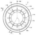
- FIG. 20 is a sectional view taken along line XX-XX in FIG.
- the refrigeration cycle 1 functions as a device that adjusts the temperature of air blown into the vehicle interior in a vehicle air conditioner that performs air conditioning of the vehicle interior.
- the refrigeration cycle 1 includes a compressor 2 that compresses and discharges refrigerant, a radiator 3 that radiates heat discharged from the compressor 2, an expansion valve 4 that decompresses refrigerant that flows out of the radiator 3, and decompresses the expansion valve 4.
- the evaporator 5 for evaporating the refrigerant is composed of a closed circuit connected in an annular shape.
- Rotational driving force output from the engine 6 via the power transmission device 10 is transmitted to the compressor 2 via the V belt 7 and the power transmission device 10.
- the engine 6 constitutes a drive source that outputs a rotational driving force
- the compressor 2 constitutes a drive target device.
- the engine 6 of the present embodiment is equipped with a generator ISG with a motor function capable of assisting the output of the engine 6 in order to reduce fuel consumption.
- the motor function generator ISG is a device in which a function as a starter for starting the engine 6 and a function as a generator are integrated.
- the motor function generator ISG is connected to the rotation output portion 6 a of the engine 6 via the V belt 7.
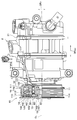
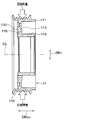
- FIG. 2 is a schematic diagram schematically showing both the power transmission device 10 and the compressor 2 of the first embodiment. 2, in order to illustrate the internal structure of the power transmission device 10, the power transmission device 10 is shown in a half sectional view.
- DRax shown in FIG. 2 indicates the axial direction of the shaft 20 extending along the axial center CL of the shaft 20 of the compressor 2.
- DRr shown in FIG. 2 indicates the radial direction of the shaft 20 orthogonal to the axial direction DRax. The same applies to drawings other than FIG.
- the power transmission device 10 is a device that intermittently transmits the rotational driving force output from the engine 6 that is a drive source for vehicle travel to the compressor 2 that is a drive target device. As shown in FIG. 1, the power transmission device 10 is connected to a rotation output unit 6 a of the engine 6 via a V-belt 7.
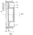
- the power transmission device 10 is connected to the rotor 11, the rotor 11, the driven-side rotating body 13 that rotates together with the shaft 20, and the electromagnetic attraction force that connects the driven-side rotating body 13 and the rotor 11. It has the electromagnet 12 which generate
- the outer cylindrical portion 111 is formed in a cylindrical shape and is arranged coaxially with the shaft 20.
- the inner cylindrical portion 112 is configured in a cylindrical shape, and is disposed on the inner peripheral side of the outer cylindrical portion 111 and is disposed coaxially with the shaft 20.
- the end surface portion 113 is a connecting portion that connects one end sides of the outer cylindrical portion 111 and the inner cylindrical portion 112 in the axial direction DRax.
- the end surface portion 113 is configured in a disk shape. That is, the end surface portion 113 extends in the radial direction DRr of the shaft 20, and a circular through hole penetrating the front and back is formed in the center portion thereof.
- the rotor 11 of the present embodiment has a C-shaped cross section in the axial direction DRax of the shaft 20.
- An annular space having the end surface portion 113 as a bottom surface portion is formed between the outer cylindrical portion 111 and the inner cylindrical portion 112.
- the space formed between the outer cylindrical portion 111 and the inner cylindrical portion 112 is coaxial with the shaft 20. As shown in FIG. 2, the electromagnet 12 is disposed in a space formed between the outer cylindrical portion 111 and the inner cylindrical portion 112.
- the electromagnet 12 includes a stator 121, a coil 122 disposed inside the stator 121, and the like.
- the stator 121 is formed in a ring shape with a ferromagnetic material such as iron.
- the coil 122 is fixed to the stator 121 in a state of being molded with an insulating resin material such as an epoxy resin.
- the electromagnet 12 is energized by a control voltage output from a control device (not shown).
- the outer cylindrical portion 111, the inner cylindrical portion 112, and the end surface portion 113 are integrally formed of a metallic ferromagnetic material (for example, a steel material).
- the outer cylindrical portion 111, the inner cylindrical portion 112, and the end surface portion 113 constitute a part of a magnetic circuit generated by energizing the electromagnet 12.
- a V-groove portion 114 in which a plurality of V-shaped grooves are formed is formed on the outer peripheral side of the outer cylindrical portion 111.
- a V-belt 7 that transmits the rotational driving force output from the engine 6 is stretched over the V-groove 114.
- the V-groove portion 114 may be formed of a resin or the like instead of a metallic ferromagnetic material.
- the outer peripheral side of the ball bearing 19 is fixed to the inner peripheral side of the inner cylindrical portion 112.
- a cylindrical boss portion 22 protruding from the housing 21 constituting the outer shell of the compressor 2 toward the power transmission device 10 is fixed to the inner peripheral side of the ball bearing 19.
- the rotor 11 is fixed to the housing 21 of the compressor 2 so as to be rotatable.
- the boss portion 22 covers the root portion of the shaft 20 exposed outside the housing.
- the outer surface on one end side in the axial direction DRax in the end surface portion 113 constitutes the rotor side friction surface 110 that comes into contact with the armature 14 when the rotor 11 and the armature 14 of the driven side rotating body 13 described later are connected. is doing.
- the rotor side friction surface 110 is formed with a slit hole portion 115 for magnetic shielding at an intermediate portion in the radial direction DRr.
- the slit hole 115 has an arc shape extending along the circumferential direction of the rotor 11, and a plurality of slit holes 115 are formed on the rotor-side friction surface 110.
- the magnetic flux flow in the radial direction DRr is blocked by the slit hole 115.
- a friction member for increasing the coefficient of friction is disposed on a part of the rotor-side friction surface 110.
- the friction member is made of a nonmagnetic material.
- a material obtained by solidifying alumina with a resin, a sintered body of metal powder such as aluminum, or the like can be used.
- the driven-side rotator 13 includes an armature 14, a hub 15, and a leaf spring 16 as shown in FIGS.
- the armature 14 is an annular plate member that extends in the radial direction DRr and has a through hole that penetrates the front and back at the center.
- the armature 14 is formed of the same kind of ferromagnetic material as the rotor 11 (for example, steel material).
- the armature 14 together with the rotor 11 constitutes a part of a magnetic circuit generated when the electromagnet 12 is energized.
- the armature 14 is disposed to face the rotor-side friction surface 110 with a predetermined minute gap (for example, about 0.5 mm).
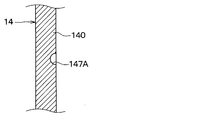
- a flat portion of the armature 14 that faces the rotor-side friction surface 110 forms an armature-side friction surface 140 that contacts the rotor-side friction surface 110 when the rotor 11 and the armature 14 are connected.
- a slit hole portion 141 for magnetic shielding is formed at an intermediate portion in the radial direction DRr.
- the slit hole portion 141 has an arc shape extending along the circumferential direction of the armature 14, and a plurality of the slit hole portions 141 are formed with respect to the armature 14.
- the magnetic flux flow in the radial direction DRr is blocked by the slit hole portion 141.
- the armature 14 is divided into an outer peripheral part 142 located on the outer peripheral side of the slit hole part 141 and an inner peripheral part 143 located on the inner peripheral side of the slit hole part 141.
- the outer peripheral portion 142 of the armature 14 is connected to the outer peripheral side of the leaf spring 16 by a fastening member 144 such as a rivet.
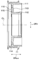
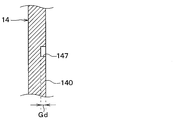
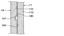
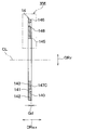
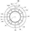
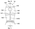
- the armature-side friction surface 140 of the present embodiment is formed with a plurality of grooves 147 extending in a slit shape from the inner peripheral side to the outer peripheral side with the axis CL of the shaft 20 as the center.
- the plurality of grooves 147 are formed radially so as to be arranged at equal intervals in the circumferential direction of the armature-side friction surface 140. Twelve grooves 147 are formed in the armature side friction surface 140 of the present embodiment. Note that the number of the groove portions 147 is not limited to twelve, and for example, about eight grooves may be provided.
- the plurality of groove portions 147 of the present embodiment are formed from an inner peripheral side end portion 145 that is an end portion on the inner peripheral side of the armature side friction surface 140 to an outer peripheral side end portion 146 that is an end portion on the outer peripheral side of the armature side friction surface 140. It extends to the front. That is, the plurality of groove portions 147 are such that outer groove end portions 148, which are outer ends thereof, are positioned on the inner side of the outer peripheral side end portion 146 on the armature-side friction surface 140.
- the groove outer end portion 148 is located closer to the outer peripheral side end portion 146 than the inner peripheral side end portion 145 in the armature side friction surface 140. Thereby, as for the some groove part 147 of this embodiment, the groove outer end part 148 is located in the outer side of radial direction DRr rather than the slit hole part 141.
- the plurality of groove portions 147 of the present embodiment extend linearly along the radial direction DRr of the shaft 20.
- the plurality of grooves 147 may partially or entirely extend linearly in a direction intersecting the radial direction DRr of the shaft 20, or may be partially or entirely curved.
- the groove width Gw and the groove depth Gd of the plurality of groove portions 147 of the present embodiment are substantially constant. Furthermore, as shown in FIG. 7, the plurality of groove portions 147 of the present embodiment has a rectangular cross-sectional shape.
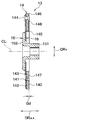
- the hub 15 constitutes a connecting member that connects the armature 14 to the shaft 20 of the compressor 2 via a leaf spring 16 or the like.
- the hub 15 is made of an iron-based metal material.
- the hub 15 of the present embodiment includes a cylindrical tubular portion 151 and a connecting flange portion 152.
- the cylindrical portion 151 is disposed coaxially with the shaft 20.
- the cylindrical portion 151 is formed with an insertion hole into which one end side of the shaft 20 can be inserted.
- the insertion hole is a through hole extending along the axial direction DRax of the shaft 20.
- the hub 15 and the shaft 20 of the present embodiment are connected by a fastening technique such as a screw in a state where one end side in the axial direction DRax is inserted into the insertion hole of the cylindrical portion 151.
- the leaf spring 16 is a member that applies an urging force to the armature 14 in a direction away from the rotor 11.
- the biasing force of the leaf spring 16 causes the armature-side friction surface 140 and the rotor-side friction surface 110 to be interposed. A gap is created.
- the leaf spring 16 is composed of a circular plate-like member made of an iron-based metal material.
- a plate-like elastic member is interposed between the leaf spring 16 and the armature 14.
- the leaf spring 16 and the armature 14 are integrally connected by a fastening member 144 with an elastic member interposed.
- the elastic member performs a torque transmission function between the leaf spring 16 and the armature 14 and also functions to suppress vibration.
- the elastic member is made of, for example, a rubber-based elastic material.
- the operation of the power transmission device 10 of this embodiment will be described.
- the electromagnet 12 when the electromagnet 12 is in a non-energized state, the electromagnetic attractive force of the electromagnet 12 is not generated. For this reason, the armature 14 is held at a position away from the end surface portion 113 of the rotor 11 by a biasing force of the leaf spring 16.
- the power transmission device 10 when the electromagnet 12 is energized, the power transmission device 10 generates an electromagnetic attractive force of the electromagnet 12.
- the armature 14 is attracted to the rotor 11 by being attracted to the end surface portion 113 side of the rotor 11 against the biasing force of the leaf spring 16 by the electromagnetic attraction force of the electromagnet 12.
- adhesion between the rotor-side friction surface 110 and the armature-side friction surface 140 occurs when the power transmission device 10 is applied to the engine 6 on which the motor function generator ISG is mounted. It has been found that there is a particular tendency to occur.
- the present inventors diligently studied the factors that cause a large growth of the melt generated by the adhesion between the rotor-side friction surface 110 and the armature-side friction surface 140. As a result, as shown in FIG. 8, when an excessive compressive load is applied to the rotor 11, the inner peripheral side of the rotor 11 bulges toward the armature 14, and the surface pressure of each friction surface 110, 140 is locally high. As a result, it was found that one factor is that the melt is biased toward the inner periphery.
- a plurality of grooves 147 are provided on the armature side friction surface 140 in order to suppress the growth of the melt produced by the adhesion between the rotor side friction surface 110 and the armature side friction surface 140.
- the plurality of groove portions 147 of the present embodiment extend from the inner peripheral side end portion 145 of the armature side friction surface 140 to the front side of the outer peripheral side end portion 146. That is, the plurality of groove portions 147 of the present embodiment are formed in a region from the inner peripheral side end portion 145 to the front side of the outer peripheral side end portion 146, which is a region where adhesion on the armature side friction surface 140 is likely to occur.
- the rotor-side friction surface 110 and the armature-side friction surface 140 are compared with a configuration in which the plurality of groove portions 147 extend over the entire region from the inner peripheral side end 145 to the outer peripheral side end 146 of the armature-side friction surface 140.
- the contact area with the can be ensured. Since the outer peripheral side end portion 146 side region of the armature side friction surface 140 has a higher peripheral speed than the inner peripheral side end portion 145 side region, the friction between the rotor side friction surface 110 and the armature side friction surface 140 is high. It becomes an area that is hard to stick by wearing.
- the power transmission device 10 secures a contact area between the rotor-side friction surface 110 and the armature-side friction surface 140, while maintaining the contact between the rotor-side friction surface 110 and the armature-side friction surface 140.
- Various problems caused by wearing can be suppressed.
- the power transmission device 10 of the present embodiment has a structure in which the rotor-side friction surface 110, the armature-side friction surface 140, and the melt MC generated by adhesion are difficult to grow. For this reason, the power transmission device 10 of this embodiment is suitable for the engine 6 on which the generator ISG with a motor function that is particularly likely to cause adhesion between the rotor-side friction surface 110 and the armature-side friction surface 140 is mounted.
- the groove outer end portion 148 is located closer to the outer peripheral side end portion 146 than the inner peripheral side end portion 145 of the armature side friction surface 140. This makes it easier for the plurality of grooves 147 to flow in the melt MC generated by the adhesion between the rotor-side friction surface 110 and the armature-side friction surface 140. For this reason, various problems caused by adhesion between the rotor-side friction surface 110 and the armature-side friction surface 140 can be sufficiently suppressed.
- the armature-side friction surface 140 may have a plurality of grooves 147 ⁇ / b> A whose cross-sectional shape is a round shape (that is, a C shape).
- FIG. 12 is a cross-sectional view corresponding to FIG. 7 of the first embodiment.
- the armature-side friction surface 140 may have a plurality of grooves 147 ⁇ / b> B having a V-shaped cross section.
- FIG. 13 is a cross-sectional view corresponding to FIG. 7 of the first embodiment.
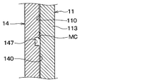
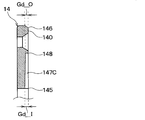
- the groove depths Gd of the plurality of grooves 147C formed on the armature-side friction surface 140 are different from the plurality of grooves 147 of the first embodiment.
- the armature side friction surface 140 of the present embodiment has a plurality of grooves 147C.
- the groove depth Gd on the inner side of the plurality of groove portions 147 ⁇ / b> C is increased in consideration of the fact that a melt due to adhesion tends to grow on the inner peripheral side of the armature-side friction surface 140.
- the groove depth Gd of the plurality of groove portions 147 ⁇ / b> C of the present embodiment increases from the outer side to the inner side on the armature side friction surface 140. That is, in the plurality of groove portions 147C of this embodiment, the groove depth Gd_I on the inner side near the inner peripheral side end portion 145 is larger than the groove depth Gd_O on the outer side near the outer peripheral side end portion 146.
- the power transmission device 10 of the present embodiment can obtain the same effects as those of the first embodiment, which are obtained from the configuration common to the first embodiment.
- the groove depth Gd_I on the inner side of the plurality of groove portions 147C is larger than the groove depth Gd_O on the outer side. According to this, since the groove depth Gd of the groove portion 147C on the inner side where the adhesion on the armature side friction surface 140 is likely to occur is increased, the melt produced by the adhesion tends to stay in the plurality of groove portions 147C. As a result, various problems caused by adhesion between the rotor-side friction surface 110 and the armature-side friction surface 140 can be sufficiently suppressed.
- the groove depth Gd of the groove portion 147C on the outer side of the friction surface where adhesion hardly occurs is smaller than that on the inner side, so that the rotor 11 and the armature 14 are formed when the electromagnet 12 is energized.
- the magnetic resistance of the magnetic circuit can be suppressed. That is, according to this configuration, it is possible to improve the magnetic performance of the magnetic circuit formed in the rotor 11 and the armature 14 when the electromagnet 12 is energized.
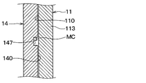
- the groove widths Gw of the plurality of groove portions 147D formed on the armature-side friction surface 140 are different from the plurality of groove portions 147 of the first embodiment.
- a plurality of groove portions 147D are formed on the armature side friction surface 140 of the present embodiment.
- the groove width Gw on the inner side of the plurality of groove portions 147 ⁇ / b> D is increased in consideration of the fact that a melt due to adhesion tends to grow on the inner peripheral side of the armature-side friction surface 140.
- the plurality of groove portions 147D of the present embodiment have a groove width Gw that increases from the outer side to the inner side on the armature side friction surface 140. That is, in the plurality of groove portions 147 ⁇ / b> D of the present embodiment, the inner groove width Gw_I close to the inner peripheral end portion 145 is larger than the outer groove width Gw_O close to the outer peripheral end portion 146.
- the power transmission device 10 of the present embodiment can obtain the same effects as those of the first embodiment, which are obtained from the configuration common to the first embodiment.
- the groove width Gw_I inside the plurality of groove portions 147D is larger than the groove width Gw_O on the outside. According to this, since the groove width Gw of the inner groove portion 147D where adhesion on the armature-side friction surface 140 is likely to occur is larger than that on the outer side, the melt produced by the adhesion easily flows into the plurality of groove portions 147D. Become. As a result, various problems caused by adhesion between the rotor-side friction surface 110 and the armature-side friction surface 140 can be sufficiently suppressed.
- the outer groove width Gw in which the adhesion on the armature side friction surface 140 is less likely to occur in the plurality of groove portions 147D of the present embodiment is smaller than the inner side, the rotor side friction surface 110 and the armature side friction surface 140 are reduced. A sufficient contact area can be secured.
- the power transmission device 10 of the present embodiment is different from the first embodiment in that a plurality of grooves 118 are also formed in the rotor side friction surface 110.
- a plurality of grooves 118 and 147 are formed on both the rotor side friction surface 110 and the armature side friction surface 140.
- the armature-side friction surface 140 is the same as that in the first embodiment, and a description thereof will be omitted.
- the rotor 11 has a plurality of grooves extending in a slit shape from the inner peripheral side to the outer peripheral side around the axis CL of the shaft 20 on the rotor-side friction surface 110. 118 is formed.
- the plurality of grooves 118 are formed radially so as to be arranged at equal intervals in the circumferential direction of the rotor-side friction surface 110. Twelve grooves 118 are formed on the rotor side friction surface 110 of the present embodiment. Note that the number of the groove portions 118 is not limited to twelve, and for example, about eight grooves may be provided.
- the plurality of groove portions 118 are formed from an inner peripheral side end portion 116 that is an inner peripheral end portion of the rotor side friction surface 110 to an outer peripheral side end portion 117 that is an outer peripheral end portion of the rotor side friction surface 110. It extends to the front. That is, in the plurality of groove portions 118, the groove outer end portion 119, which is an outer end portion thereof, is located on the inner peripheral side with respect to the outer peripheral side end portion 117 in the rotor side friction surface 110.
- the groove outer end portion 119 is positioned closer to the outer peripheral side end portion 117 than the inner peripheral side end portion 116 in the rotor side friction surface 110. Thereby, as for the some groove part 118 of this embodiment, the groove outer end part 119 is located in the outer side of radial direction DRr rather than the slit hole part 115.
- the plurality of groove portions 118 of the present embodiment extend linearly along the radial direction DRr of the shaft 20.
- some or all of the plurality of grooves 118 may extend linearly in a direction intersecting the radial direction DRr of the shaft 20, or some or all may be curved.
- the groove width Gw and the groove depth Gd of the plurality of groove portions 118 of the present embodiment are substantially constant.
- the cross-sectional shape of the groove part 118 is a rectangular shape in the some groove part 118 of this embodiment.
- the power transmission device 10 of the present embodiment can obtain the same effects as those of the first embodiment, which are obtained from the configuration common to the first embodiment.
- a plurality of grooves 118 and 147 are formed on both the rotor-side friction surface 110 and the armature-side friction surface 140. According to this, it is possible to secure a sufficient space for the melt produced by the adhesion between the rotor-side friction surface 110 and the armature-side friction surface 140 to flow in, so that the melt produced by the adhesion grows greatly. Can be sufficiently suppressed. As a result, various problems caused by adhesion between the rotor-side friction surface 110 and the armature-side friction surface 140 can be sufficiently suppressed.
- the present invention is not limited to this.
- the plurality of grooves 118 formed on the rotor side friction surface 110 may have a different groove shape from the plurality of grooves 147 formed on the armature side friction surface 140.
- the groove outer end portions 119 and 148 of the plurality of groove portions 118 and 147 are positioned closer to the outer peripheral end portions 117 and 146 than the inner peripheral end portions 116 and 145 of the friction surface. Although desirable, it is not limited to this.
- the plurality of groove portions 118 and 147 may be formed such that the groove outer end portions 119 and 148 are located closer to the inner peripheral side end portions 116 and 145 of the friction surface than the outer peripheral side end portions 117 and 146. Good.
- the power transmission device 10 may have a configuration in which a plurality of grooves 118 are formed only on the rotor side friction surface 110, for example.
- the power transmission device 10 may be configured such that the armature 14 and the hub 15 are connected via an elastic member such as rubber, for example.
- the present invention is not limited thereto.
- the power transmission device 10 of the present disclosure can be applied to the engine 6 in which the generator with motor function ISG is not mounted.
- the present invention is not limited thereto.
- the power transmission device 10 of the present disclosure can be applied to a device for intermittently transmitting power between a drive source such as the engine 6 or an electric motor and a generator that is operated by a rotational driving force.
- the power transmission device has an inner peripheral side end portion on at least one of the rotor-side friction surface and the armature-side friction surface.
- a plurality of grooves extending from the outer periphery side to the front of the outer peripheral side end are formed.
- the outer groove end located outside is located closer to the outer peripheral end than the inner peripheral end. According to this, since the melt produced by the adhesion easily flows into the plurality of grooves, various problems caused by the adhesion between the friction surface of the rotor and the friction surface of the armature can be sufficiently suppressed.
- the groove depth inside the plurality of groove portions is larger than the groove depth outside. According to this, since the groove depth of the groove portion on the inner side of the friction surface where adhesion is likely to occur is increased, the melt produced by the adhesion tends to stay in the plurality of groove portions. As a result, various problems caused by adhesion between the friction surface of the rotor and the friction surface of the armature can be sufficiently suppressed. Further, since the groove depth of the groove portion on the outer side of the friction surface where adhesion is difficult to occur is smaller than that on the inner side, it is possible to suppress the magnetic resistance of the magnetic circuit formed in the rotor and the armature when the electromagnet is energized. . That is, according to this configuration, it is possible to improve the magnetic performance of the magnetic circuit formed in the rotor and the armature when the electromagnet is energized.
- the groove width on the inner side of the plurality of groove portions is larger than the groove width on the outer side. According to this, since the groove width of the groove portion on the inner side of the friction surface where adhesion is likely to occur is larger than that on the outer side, the melt produced by the adhesion easily flows into the plurality of groove portions. As a result, various problems caused by adhesion between the friction surface of the rotor and the friction surface of the armature can be sufficiently suppressed. Further, since the groove width of the groove portion on the outer side of the friction surface where adhesion hardly occurs is smaller than that on the inner side, a sufficient contact area between the rotor side friction surface and the armature side friction surface can be ensured.
- the plurality of grooves are formed on both the rotor side friction surface and the armature side friction surface. According to this, it is possible to sufficiently secure a space into which the melt produced by the adhesion flows, so that the melt produced by the adhesion can be sufficiently prevented from growing. As a result, various problems caused by adhesion between the friction surface of the rotor and the friction surface of the armature can be sufficiently suppressed.
- the power transmission device is equipped with a generator with a motor function that assists the output of the drive source with respect to the drive source.
- the power transmission device of the present disclosure has a structure in which a melt generated by adhesion between the rotor-side friction surface and the armature-side friction surface is difficult to grow. For this reason, the power transmission device of the present disclosure is suitable for a drive source on which a generator with a motor function that is particularly likely to cause adhesion between the rotor-side friction surface and the armature-side friction surface is mounted.
Landscapes
- Engineering & Computer Science (AREA)
- General Engineering & Computer Science (AREA)
- Physics & Mathematics (AREA)
- Electromagnetism (AREA)
- Mechanical Engineering (AREA)
- Power Engineering (AREA)
- Connection Of Motors, Electrical Generators, Mechanical Devices, And The Like (AREA)
- Mechanical Operated Clutches (AREA)
Priority Applications (3)
| Application Number | Priority Date | Filing Date | Title |
|---|---|---|---|
| CN201780077371.1A CN110073123B (zh) | 2016-12-16 | 2017-11-09 | 动力传递装置 |
| DE112017006317.5T DE112017006317T5 (de) | 2016-12-16 | 2017-11-09 | Leistungsübertragungsgerät |
| US16/409,955 US11333205B2 (en) | 2016-12-16 | 2019-05-13 | Power transmission device |
Applications Claiming Priority (2)
| Application Number | Priority Date | Filing Date | Title |
|---|---|---|---|
| JP2016-244647 | 2016-12-16 | ||
| JP2016244647A JP6645414B2 (ja) | 2016-12-16 | 2016-12-16 | 動力伝達装置 |
Related Child Applications (1)
| Application Number | Title | Priority Date | Filing Date |
|---|---|---|---|
| US16/409,955 Continuation US11333205B2 (en) | 2016-12-16 | 2019-05-13 | Power transmission device |
Publications (1)
| Publication Number | Publication Date |
|---|---|
| WO2018110167A1 true WO2018110167A1 (ja) | 2018-06-21 |
Family
ID=62558997
Family Applications (1)
| Application Number | Title | Priority Date | Filing Date |
|---|---|---|---|
| PCT/JP2017/040492 Ceased WO2018110167A1 (ja) | 2016-12-16 | 2017-11-09 | 動力伝達装置 |
Country Status (5)
| Country | Link |
|---|---|
| US (1) | US11333205B2 (enExample) |
| JP (1) | JP6645414B2 (enExample) |
| CN (1) | CN110073123B (enExample) |
| DE (1) | DE112017006317T5 (enExample) |
| WO (1) | WO2018110167A1 (enExample) |
Families Citing this family (2)
| Publication number | Priority date | Publication date | Assignee | Title |
|---|---|---|---|---|
| JP6645414B2 (ja) | 2016-12-16 | 2020-02-14 | 株式会社デンソー | 動力伝達装置 |
| US12104659B2 (en) * | 2019-10-25 | 2024-10-01 | The Hilliard Corporation | Flexible armature plate for an electro-magnetic overrunning clutch |
Citations (6)
| Publication number | Priority date | Publication date | Assignee | Title |
|---|---|---|---|---|
| US3550739A (en) * | 1968-10-25 | 1970-12-29 | Eaton Yale & Towne | Friction coupling |
| JPS5719233U (enExample) * | 1980-07-04 | 1982-02-01 | ||
| JPS636224A (ja) * | 1986-06-24 | 1988-01-12 | Taiho Kogyo Co Ltd | 電磁クラツチ装置 |
| JPH0519671U (ja) * | 1991-08-22 | 1993-03-12 | 株式会社ゼクセル | マグネツトクラツチ |
| JP2003314584A (ja) * | 2002-04-19 | 2003-11-06 | Mitsubishi Heavy Ind Ltd | 電磁クラッチ |
| JP2004124815A (ja) * | 2002-10-02 | 2004-04-22 | Ntn Corp | 車両用ベルト動力伝達装置 |
Family Cites Families (9)
| Publication number | Priority date | Publication date | Assignee | Title |
|---|---|---|---|---|
| US3624767A (en) * | 1970-08-05 | 1971-11-30 | Warner Electric Brake & Clutch | Self-adjusting clutch or brake |
| JPS60205026A (ja) * | 1984-03-28 | 1985-10-16 | Ogura Clutch Co Ltd | 電磁連結装置 |
| US5195625A (en) * | 1992-05-29 | 1993-03-23 | General Motors Corporation | Torque cushion for electromagnetic clutch |
| US5273409A (en) * | 1993-05-20 | 1993-12-28 | General Motors Corporation | Compressor assembly including an electromagnetically triggered pressure actuated internal clutch |
| JP2002098170A (ja) | 2000-09-20 | 2002-04-05 | Mitsubishi Heavy Ind Ltd | 電磁クラッチ |
| JP2003240018A (ja) | 2002-02-20 | 2003-08-27 | Mitsubishi Heavy Ind Ltd | 電磁クラッチ |
| CN203847593U (zh) * | 2014-05-12 | 2014-09-24 | 苏州新智机电工业有限公司 | 汽车空调压缩机上的两体结构线圈外壳组件 |
| JP6645415B2 (ja) | 2016-12-16 | 2020-02-14 | 株式会社デンソー | 動力伝達装置 |
| JP6645414B2 (ja) | 2016-12-16 | 2020-02-14 | 株式会社デンソー | 動力伝達装置 |
-
2016
- 2016-12-16 JP JP2016244647A patent/JP6645414B2/ja not_active Expired - Fee Related
-
2017
- 2017-11-09 WO PCT/JP2017/040492 patent/WO2018110167A1/ja not_active Ceased
- 2017-11-09 DE DE112017006317.5T patent/DE112017006317T5/de not_active Withdrawn
- 2017-11-09 CN CN201780077371.1A patent/CN110073123B/zh not_active Expired - Fee Related
-
2019
- 2019-05-13 US US16/409,955 patent/US11333205B2/en active Active
Patent Citations (6)
| Publication number | Priority date | Publication date | Assignee | Title |
|---|---|---|---|---|
| US3550739A (en) * | 1968-10-25 | 1970-12-29 | Eaton Yale & Towne | Friction coupling |
| JPS5719233U (enExample) * | 1980-07-04 | 1982-02-01 | ||
| JPS636224A (ja) * | 1986-06-24 | 1988-01-12 | Taiho Kogyo Co Ltd | 電磁クラツチ装置 |
| JPH0519671U (ja) * | 1991-08-22 | 1993-03-12 | 株式会社ゼクセル | マグネツトクラツチ |
| JP2003314584A (ja) * | 2002-04-19 | 2003-11-06 | Mitsubishi Heavy Ind Ltd | 電磁クラッチ |
| JP2004124815A (ja) * | 2002-10-02 | 2004-04-22 | Ntn Corp | 車両用ベルト動力伝達装置 |
Also Published As
| Publication number | Publication date |
|---|---|
| JP2018096523A (ja) | 2018-06-21 |
| US20190264758A1 (en) | 2019-08-29 |
| JP6645414B2 (ja) | 2020-02-14 |
| DE112017006317T5 (de) | 2019-09-19 |
| CN110073123B (zh) | 2020-06-26 |
| CN110073123A (zh) | 2019-07-30 |
| US11333205B2 (en) | 2022-05-17 |
Similar Documents
| Publication | Publication Date | Title |
|---|---|---|
| WO2018110167A1 (ja) | 動力伝達装置 | |
| CN107110244A (zh) | 电磁离合器 | |
| JP6645415B2 (ja) | 動力伝達装置 | |
| CN112105831B (zh) | 电磁离合器 | |
| JP6597746B2 (ja) | 動力伝達装置 | |
| US9835205B2 (en) | Friction clutch | |
| JP6680272B2 (ja) | 動力伝達装置 | |
| WO2019239837A1 (ja) | 動力伝達装置 | |
| JP6747399B2 (ja) | 動力伝達装置 | |
| JP5910472B2 (ja) | クラッチ機構 | |
| JP6569600B2 (ja) | クラッチおよびその製造方法 | |
| JP6606972B2 (ja) | 動力伝達装置 | |
| JP2019124267A (ja) | トルク伝達装置 | |
| JP7255528B2 (ja) | トルク伝達装置 | |
| JP2020176710A (ja) | 動力断続装置 | |
| JP2008025598A (ja) | 電磁クラッチ | |
| JP2017219092A (ja) | 動力伝達装置 |
Legal Events
| Date | Code | Title | Description |
|---|---|---|---|
| 121 | Ep: the epo has been informed by wipo that ep was designated in this application |
Ref document number: 17880907 Country of ref document: EP Kind code of ref document: A1 |
|
| 122 | Ep: pct application non-entry in european phase |
Ref document number: 17880907 Country of ref document: EP Kind code of ref document: A1 |