WO2018105161A1 - チャック装置 - Google Patents
チャック装置 Download PDFInfo
- Publication number
- WO2018105161A1 WO2018105161A1 PCT/JP2017/024757 JP2017024757W WO2018105161A1 WO 2018105161 A1 WO2018105161 A1 WO 2018105161A1 JP 2017024757 W JP2017024757 W JP 2017024757W WO 2018105161 A1 WO2018105161 A1 WO 2018105161A1
- Authority
- WO
- WIPO (PCT)
- Prior art keywords
- rotating cylinder
- rotating
- ratchet teeth
- spring body
- locking spring
- Prior art date
- Legal status (The legal status is an assumption and is not a legal conclusion. Google has not performed a legal analysis and makes no representation as to the accuracy of the status listed.)
- Ceased
Links
Images


Classifications
-
- B—PERFORMING OPERATIONS; TRANSPORTING
- B23—MACHINE TOOLS; METAL-WORKING NOT OTHERWISE PROVIDED FOR
- B23B—TURNING; BORING
- B23B31/00—Chucks; Expansion mandrels; Adaptations thereof for remote control
- B23B31/02—Chucks
- B23B31/10—Chucks characterised by the retaining or gripping devices or their immediate operating means
- B23B31/12—Chucks with simultaneously-acting jaws, whether or not also individually adjustable
- B23B31/1207—Chucks with simultaneously-acting jaws, whether or not also individually adjustable moving obliquely to the axis of the chuck in a plane containing this axis
- B23B31/123—Chucks with simultaneously-acting jaws, whether or not also individually adjustable moving obliquely to the axis of the chuck in a plane containing this axis with locking arrangements
-
- B—PERFORMING OPERATIONS; TRANSPORTING
- B23—MACHINE TOOLS; METAL-WORKING NOT OTHERWISE PROVIDED FOR
- B23B—TURNING; BORING
- B23B31/00—Chucks; Expansion mandrels; Adaptations thereof for remote control
- B23B31/02—Chucks
- B23B31/10—Chucks characterised by the retaining or gripping devices or their immediate operating means
- B23B31/12—Chucks with simultaneously-acting jaws, whether or not also individually adjustable
- B23B31/1207—Chucks with simultaneously-acting jaws, whether or not also individually adjustable moving obliquely to the axis of the chuck in a plane containing this axis
- B23B31/1238—Jaws movement actuated by a nut with conical screw-thread
-
- B—PERFORMING OPERATIONS; TRANSPORTING
- B23—MACHINE TOOLS; METAL-WORKING NOT OTHERWISE PROVIDED FOR
- B23B—TURNING; BORING
- B23B2260/00—Details of constructional elements
- B23B2260/136—Springs
Definitions
- the present invention relates to a chuck device.
- Patent Document 1 a rotating cylinder provided in a main body is rotated, and the rotating nut rotated together with the rotating cylinder is screwed with the rotating nut.
- a chuck device that extends and retracts a claw and holds a tool with the claw.
- the chuck device disclosed in Patent Document 1 has a loosening prevention mechanism that uses a ratchet tooth provided in the main body and a locking spring body that is provided between the rotating cylinder and the ratchet tooth and engages with the ratchet tooth. Is provided. In a state where the ratchet teeth and the locking spring body are locked, a part of the locking spring body is fitted into a recess provided on the inner surface of the rotating cylinder, and the locked state is maintained.
- the present invention has been made in view of the above-described situation, and when the rotating cylinder is rotated in the tightening direction and the tightening is completed, when the hand is released and the rotational force in the tightening direction is reduced to zero, the ratchet
- a lock release mechanism that forcibly releases the lock between the teeth and the lock spring body, it is easy to rotate the rotating cylinder in the loosening direction when changing the tool, and wear of the ratchet teeth is reduced. It is an object of the present invention to provide a chuck device that is extremely practical and capable of suppressing the lifetime.
- a plurality of claws 3 inserted into a hole 2 a provided at the tip of the main body 2 are expanded and contracted, and the tool 4 is held by the claws 3.
- An annular rotating body 8 that is engaged with the claw 3 and rotates together with the rotating cylinder 1 is fitted into the main body 2 inward of the rotating cylinder 1, and is attached to the main body 2.
- 2 or the rotating body 8 is provided with an annular ratchet tooth 5, and a detachable locking spring body 9 for locking with the ratchet tooth 5 is provided to rotate the rotating cylinder 1 in the tightening direction.
- the present invention relates to a chuck device characterized in that a stop release mechanism is provided.
- the 2nd aspect of this invention rotates the said rotation cylinder 1 in the tightening direction on the inner surface of the said rotation cylinder 1 in the 1st aspect
- the to-be-pressed of the said latching spring body 9 is carried out.
- a pressing deformation portion 11 is provided for pressing and elastically deforming the portion 9a.
- the rotational force in the tightening direction is reduced to zero.
- the ratchet teeth 5 and the locking spring body 9 are forcibly locked.
- the present invention relates to a chuck device characterized in that the unlocking mechanism for releasing is employed.
- the chuck device when the rotating cylinder 1 is rotated in a tightening direction in which the claw 3 is contracted, the ratchet teeth 5 are engaged.
- the chuck device is characterized in that a pressing portion 10 that presses the locking spring body 9 that is not engaged and is locked with the ratchet teeth 5 is provided on the inner surface of the rotating cylinder 1.
- the present invention is configured as described above, it is easy to rotate the rotating cylinder in the loosening direction at the time of tool replacement, and it is extremely practical for suppressing the wear of the ratchet teeth and extending the life. It becomes a chuck device.
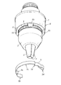
- FIG. 1 is an exploded perspective view of Example 1.
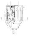
- FIG. 1 is a front view in which a part of Example 1 is cut away.
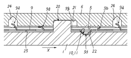
- FIG. 3 is a cross-sectional view taken along line AA in FIG. 2.
- FIG. 3 is a cross-sectional view taken along line AA in FIG. 2. It is a disassembled explanatory perspective view of Example 2.
- FIG. 6 is a front view in which a part of Example 2 is cut away. It is an expanded view of the latching spring body of Example 2, and its peripheral member. It is an expanded view of the latching spring body of Example 2, and its peripheral member. It is an expanded view of the latching spring body of Example 2, and its peripheral member.
- the locking spring body 9 fitted into the recess on the inner surface of the rotating cylinder 1 is provided before the rotating cylinder 1 is rotated in the loosening direction, as in Patent Document 1. It is not necessary to twist the rotating cylinder 1 by applying a suitable force in order to escape a part from the recess, and the claw 3 can be expanded by instantly rotating the rotating cylinder 1 in the loosening direction. Become.
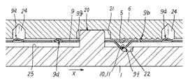
- the first embodiment is a chuck device in which a plurality of claws 3 inserted into a hole 2 a provided at the tip of a main body 2 are expanded and contracted by rotating a rotating cylinder 1, and a tool 4 is clamped by the claws 3.
- the main body 2 is provided with an annular ratchet tooth 5, and the main body 2 is engaged with the claw 3 inwardly of the rotating cylinder 1 and is rotated with the rotating cylinder 1.
- a rotating body 8 is fitted, and a detachable locking spring body 9 that is locked to the ratchet teeth 5 is disposed on the outer side of the ratchet teeth 5.
- the locking spring body 9 is provided in a state of rotating around the ratchet teeth 5 as it rotates, and the locking spring body 9 is attached to the rotating body 1 by means of concave and convex fitting means, and the rotating cylinder 1 is attached to the claw.
- the locking spring which is not locked with the ratchet teeth 5 when rotating in the tightening direction in which 3 is contracted
- a pressing portion 10 that presses 9 and engages with the ratchet teeth 5 is provided on the inner surface of the rotating cylinder 1, and the rotating cylinder 1 is rotated in a loosening direction in which the claw 3 is expanded.
- the locking spring body 9 is configured not to be locked with the ratchet teeth 5, and further, the ratchet teeth 5 and the locking spring body 9 are locked by rotating the rotating cylinder 1 in the tightening direction. After the gripping force on the tool 4 reaches a predetermined value, when the turning force in the tightening direction is reduced to zero, the latch that forcibly releases the latching of the ratchet teeth 5 and the locking spring body 9 A release mechanism is provided.
- Example 1 is used for an electric rotating tool such as a so-called hammer drill, vibration drill, or driver drill that applies vibration or impact.
- the main body 2 is made of metal (for example, steel). As shown in FIGS. 1 to 4, the hole 2 a formed in the main body 2 is provided with three claws 3 in an inclined state, and an annular nut that is screwed with a screw portion 3 a formed on the outer surface of the claw 3. A body 6 is provided on the claw 3 in a fitted state.
- This nut body 6 is a split nut body 6 and is retained by a shape retaining ring 7.
- the rotating body 8 in the claims rotates together with the rotating cylinder 1 and is screwed with the claw 3.
- the rotating body 8 includes the nut body 6 and the shape retaining ring 7. . Therefore, in the first embodiment, the nut body 6 and the rotating cylinder 1 are connected, and the rotating cylinder 1 is rotated to rotate the nut body 6.
- the shape retaining ring 7 and the rotating cylinder 1 rotate. It is good also as a structure which connects the cylinder 1 and rotates the rotation cylinder 1 and rotates the shape-retaining ring 7 and the nut body 6.
- the nut body 6 has projections 6 a, 6 b, 6 c, 6 d for engaging with projections 16, 17 provided on the inner surface of the rotating cylinder 1 and transmitting the rotational force of the rotating cylinder 1 to the nut body 6.
- a locking spring body 9 is attached to the protrusions 6a and 6b in a co-rotating state with respect to the nut body 6.
- the locking spring body 9 includes a folded curved portion 9a as a pressed portion 9a formed by folding a base end portion into a U shape, and a distal end locking portion 9b at the distal end portion.
- the intermediate part 9c is attached so as to be fitted over the two convex parts 6a and 6b.
- the locking spring body 9 is bent so that curved portions 9d and 9e are formed at both ends of the intermediate portion 9c so as to face and lock the outer end surfaces of the convex portions 6a and 6b.
- the locking spring body 9 is attached to the nut body 6 in a co-rotating state by the curved portions 9 d and 9 e of the locking spring body 9 and the protrusions 6 a and 6 b of the nut body 6.
- the attachment of the locking spring body 9 and the nut body 6 is not limited to the above configuration as long as the both are in a joint state.
- the latching spring body 9 is set as the structure attached to the nut body 6 by the uneven
- annular ratchet tooth 5 is formed on the peripheral surface of the main body 2 in front of the nut body 6 and meshes with the front end locking portion 9b of the locking spring body 9. Due to the engagement between the ratchet teeth 5 and the tip engaging portion 9b, the nut body 6 appears to be rotatable only in one direction (unreversible state).
- a rotating cylinder 1 whose tip is in contact with the main body 2 is fitted on the nut body 6, and the rotating cylinder 1 rotates together with the nut body 6.
- the locking spring body 9 is made of metal (iron or steel), and is arranged around the ratchet teeth 5 so as to be supported on the inner surface of the rotating cylinder 1.
- the rotational force of the rotating cylinder 1 is transmitted in the same manner even if it is transmitted via the shape retaining ring 7.
- the locking spring body 9 is provided with a distal end locking portion 9 b that contacts the pressing portion 10 and locks with the ratchet teeth 5 at the distal end portion.
- the portion is provided with a folded curved portion 9a that comes into contact with the pressing deformation portion 11.
- the base end of the locking spring body 9 is configured not to be locked with the ratchet teeth 5.
- the locking spring body 9 can be configured as described above by bending the band material, and can be manufactured economically.
- the pressing portion 10 provided on the inner surface of the rotating cylinder 1 presses the outer surface of the locking spring body 9 with the tip tapered surface to lock the tip locking portion 9b of the locking spring body 9 to the ratchet teeth 5. It is configured to let you.
- the inner surface of the rotating cylinder 1 is provided with a convex pressing deformation portion 11 that presses the folded bending portion 9a of the locking spring body 9 and elastically deforms when the rotating cylinder 1 is rotated in the tightening direction. It has been.
- the unlocking mechanism is illustrated by rotating the rotating cylinder 1 in the tightening direction (X direction) from the unlocking state where the locking spring body 9 and the ratchet teeth 5 illustrated in FIG. 3 are not locked. 4, when the gripping force on the tool 4 is set to a predetermined value and the hand is released from the rotating cylinder 1 (when the turning force in the tightening direction is reduced to zero after the tightening is completed), the folded bending portion 9 a The pressing deformation portion 11 is pushed back by the repulsive force (restoring force) due to the return deformation, and the rotating cylinder 1 is forcibly rotated in the loosening direction (Y direction), and the engagement between the ratchet teeth 5 and the locking spring body 9. The stop is forcibly released (the state shown in FIG. 3).
- Anti-slip ridges are formed on the outer surface of the rotating cylinder 1 (synthetic resin), and the rotating cylinder 1 is received by a receiving member 15 provided at the front end at the main body 2 and at the rear end at the main body 2. Yes.
- Numeral 12 is a steel ball and 13 is a steel ball receiver. Since the steel ball receiver 13 has elasticity, the rotating cylinder 1 is prevented from rotating more than necessary in the tightening direction due to vibration or impact torque of the electric rotating tool.
- Reference numeral 14 denotes a C-shaped retaining ring of the rotating cylinder 1.
- Example 1 Since Example 1 is configured as described above, the following operational effects are achieved.
- this fastening state is automatically released by the above-described locking release mechanism when the hand is released from the rotating cylinder 1, in order to widen the claw 3, the rotating cylinder 1 is simply loosened and rotated. Just move it.
- the first embodiment can be easily rotated in the loosening direction of the rotating cylinder at the time of changing the tool, and is extremely practical in that the wear of the ratchet teeth can be suppressed and the life can be extended. .
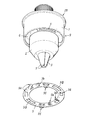
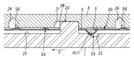
- Example 2 is an example in which the ratchet teeth 5 in Example 1 are provided not on the main body 2 but on the rotating body 8 as illustrated in FIGS.
- a ratchet tooth 5 is provided in a semicircular arc shape on the distal end surface of the nut body 6 of the rotating body 8, and between the inner surface (upward surface 25) of the distal end portion of the rotating cylinder 1 facing this ratchet tooth 5.
- the latch spring body 9 is held and the latch spring body 9 and the ratchet teeth 5 are latched.
- Two recesses 21 are provided at intervals of 180 °.
- a retaining portion 23 protrudes from the proximal end side of the shape retaining ring 7, and the retaining portion 23 is secured to the rotating cylinder 1 by retaining.
- the locking spring body 9 in the second embodiment is a thin plate-like annular member made of metal, and protrudes upward to be locked to the front end surface of the nut body 6 or a recess 24 provided on the front end surface of the nut body 6.
- a pressed portion 9a disposed on the upper side, a locking portion 9b protruding upward and locking with the ratchet teeth 5, and a protruding portion 9f protruding downward and locking with the upward surface 25 of the rotating body 1 are provided.
- a portion to be pressed 9a the engagement is formed by making a cut in the locking spring body 9 (thin plate), and bending and projecting a portion surrounded or sandwiched by the cut (three sides) upward or downward.
- a portion 9b and a protruding portion 9f are formed.
- Reference numeral 9g denotes a window hole for allowing the convex portion 20 to pass therethrough.
- the projecting portion 9f may have a shape in which a cantilever-shaped portion surrounded by cutting on three sides is bent at a substantially right angle downward, and further, the middle portion thereof is folded back and bent so that the tip is close to the thin plate. In this case, the protruding portion 9f can be satisfactorily formed even when the hardness of the thin plate is high.
- the locking spring body 9 has a protrusion 9 f that protrudes downward from the locking spring body 9 when the rotating cylinder 1 is rotated in the tightening direction.
- the locking spring body 9 is moved upward and pressed against the ratchet teeth 5 side by being pressed by the tapered surface that also serves as the pressing portion 10 and the pressing deformation portion 11, the locking portion 9 b protruding upward is the ratchet teeth 5. And the reverse rotation impossible state appears.
- the pressed portion 9a is pressed against the tip surface of the nut body 6 or the edge of the recess 24 and deformed.
- the locking between the ratchet teeth 5 and the locking portion 9b is automatically released by the restoring force of the pressed portion 9a.
- the automatic release of the locking of the locking spring body 9 with the ratchet teeth 5 is favorably performed.
- the lock release mechanism rotates the rotary cylinder 1 in the tightening direction (X direction) from the lock release state where the lock spring body 9 and the ratchet teeth 5 shown in FIG. 7 are not locked. 8 to the locked state shown in FIG. 8, and after further rotating and tightening in the state shown in FIG. 9, when the hand is released from the rotating cylinder 1 (after tightening is completed, in the tightening direction).
- the rotational force of the pressed portion 9a is zero
- the pressing deformation portion 11 (the tapered surface of the recess 22) is pushed back by the repulsive force (restoring force) due to the return deformation of the pressed portion 9a, so that the rotating cylinder 1 is loosened (Y direction).
- the ratchet teeth 5 and the locking spring body 9 are forcibly released (the state shown in FIG. 7).
Landscapes
- Engineering & Computer Science (AREA)
- Mechanical Engineering (AREA)
- Gripping On Spindles (AREA)
- Clamps And Clips (AREA)
Priority Applications (3)
| Application Number | Priority Date | Filing Date | Title |
|---|---|---|---|
| US15/775,276 US11364546B2 (en) | 2016-12-06 | 2017-07-06 | Chuck apparatus |
| CN201780004556.XA CN108472743B (zh) | 2016-12-06 | 2017-07-06 | 夹持装置 |
| DE112017000211.7T DE112017000211T5 (de) | 2016-12-06 | 2017-07-06 | Spannvorrichtung |
Applications Claiming Priority (2)
| Application Number | Priority Date | Filing Date | Title |
|---|---|---|---|
| JP2016236896A JP6787571B2 (ja) | 2016-12-06 | 2016-12-06 | チャック装置 |
| JP2016-236896 | 2016-12-06 |
Publications (1)
| Publication Number | Publication Date |
|---|---|
| WO2018105161A1 true WO2018105161A1 (ja) | 2018-06-14 |
Family
ID=62492231
Family Applications (1)
| Application Number | Title | Priority Date | Filing Date |
|---|---|---|---|
| PCT/JP2017/024757 Ceased WO2018105161A1 (ja) | 2016-12-06 | 2017-07-06 | チャック装置 |
Country Status (5)
| Country | Link |
|---|---|
| US (1) | US11364546B2 (enExample) |
| JP (1) | JP6787571B2 (enExample) |
| CN (1) | CN108472743B (enExample) |
| DE (1) | DE112017000211T5 (enExample) |
| WO (1) | WO2018105161A1 (enExample) |
Families Citing this family (2)
| Publication number | Priority date | Publication date | Assignee | Title |
|---|---|---|---|---|
| CN112338242A (zh) * | 2019-08-07 | 2021-02-09 | 浙江三鸥机械股份有限公司 | 一种自锁钻夹头 |
| USD1034129S1 (en) * | 2022-03-23 | 2024-07-09 | Biocut, Llc | Chuck |
Citations (3)
| Publication number | Priority date | Publication date | Assignee | Title |
|---|---|---|---|---|
| WO2007036082A1 (en) * | 2005-09-30 | 2007-04-05 | Zhou, Wenhua | A self-locking type manually tightened drill chuck |
| JP2010514574A (ja) * | 2006-12-23 | 2010-05-06 | ロェーム ゲーエムベーハー | ドリルチャック |
| JP2010260122A (ja) * | 2009-04-30 | 2010-11-18 | Yukiwa Seiko Inc | チャック装置 |
Family Cites Families (12)
| Publication number | Priority date | Publication date | Assignee | Title |
|---|---|---|---|---|
| FR2702975B1 (fr) * | 1993-03-26 | 1995-06-16 | Amyot Ets Sa | Mandrin porte-outil pour l'equipement d'une machine tournante, telle qu'une perceuse. |
| DE4438991C5 (de) * | 1994-10-31 | 2009-07-30 | Röhm Gmbh | Bohrfutter |
| CN2403525Y (zh) * | 2000-01-19 | 2000-11-01 | 山东威达机床工具集团总公司 | 锁紧式钻夹头 |
| EP1170079B2 (de) * | 2000-07-03 | 2010-10-06 | Röhm GmbH | Bohrfutter |
| CN1204989C (zh) * | 2000-08-18 | 2005-06-08 | 罗姆股份有限公司 | 钻卡头 |
| JP2003071618A (ja) * | 2001-08-30 | 2003-03-12 | Yukiwa Seiko Inc | チャック装置 |
| US6959931B2 (en) * | 2001-08-30 | 2005-11-01 | Yukiwa Seiko Inc. | Keyless chuck and associated method |
| CN2582790Y (zh) | 2002-11-25 | 2003-10-29 | 山东威达机械股份有限公司 | 自锁钻夹头 |
| JP4616576B2 (ja) | 2004-04-20 | 2011-01-19 | ユキワ精工株式会社 | チャック装置 |
| CN2723084Y (zh) * | 2004-09-14 | 2005-09-07 | 山东威达机械股份有限公司 | 锁紧式手紧钻夹头 |
| CN101041187B (zh) * | 2006-03-24 | 2012-06-13 | 山东威达机械股份有限公司 | 手动锁紧钻夹头 |
| CN201815693U (zh) * | 2010-09-21 | 2011-05-04 | 浙江超力机械工具制造有限公司 | 一种锁紧式钻夹头的传动机构 |
-
2016
- 2016-12-06 JP JP2016236896A patent/JP6787571B2/ja active Active
-
2017
- 2017-07-06 CN CN201780004556.XA patent/CN108472743B/zh active Active
- 2017-07-06 DE DE112017000211.7T patent/DE112017000211T5/de active Pending
- 2017-07-06 US US15/775,276 patent/US11364546B2/en active Active
- 2017-07-06 WO PCT/JP2017/024757 patent/WO2018105161A1/ja not_active Ceased
Patent Citations (3)
| Publication number | Priority date | Publication date | Assignee | Title |
|---|---|---|---|---|
| WO2007036082A1 (en) * | 2005-09-30 | 2007-04-05 | Zhou, Wenhua | A self-locking type manually tightened drill chuck |
| JP2010514574A (ja) * | 2006-12-23 | 2010-05-06 | ロェーム ゲーエムベーハー | ドリルチャック |
| JP2010260122A (ja) * | 2009-04-30 | 2010-11-18 | Yukiwa Seiko Inc | チャック装置 |
Also Published As
| Publication number | Publication date |
|---|---|
| CN108472743A (zh) | 2018-08-31 |
| JP2018089751A (ja) | 2018-06-14 |
| JP6787571B2 (ja) | 2020-11-18 |
| DE112017000211T5 (de) | 2018-08-09 |
| US11364546B2 (en) | 2022-06-21 |
| US20210170499A1 (en) | 2021-06-10 |
| CN108472743B (zh) | 2021-04-09 |
Similar Documents
| Publication | Publication Date | Title |
|---|---|---|
| JP4015857B2 (ja) | チャック装置 | |
| JP5378056B2 (ja) | チャック装置 | |
| JP4053301B2 (ja) | チャック装置 | |
| KR20180055880A (ko) | 로킹 장치를 구비한 척 | |
| JP4616576B2 (ja) | チャック装置 | |
| US6554289B1 (en) | Anti-slip type electric drill chuck | |
| JP2010046793A (ja) | ロッキングプライヤ | |
| JP2010260122A5 (enExample) | ||
| JP2003071618A (ja) | チャック装置 | |
| CN102598418A (zh) | 锁定棘轮力矩辅助件 | |
| WO2018105161A1 (ja) | チャック装置 | |
| US20210031336A1 (en) | Reversible ratchet wrench | |
| TWI674951B (zh) | 用於從凸耳上移除的帶凹槽的工具頭 | |
| CN110072657B (zh) | 具有滑动保护的夹头 | |
| TW201703933A (zh) | 操作桿之鎖定構造 | |
| US20090224491A1 (en) | Chuck wrench for a drill | |
| US7556269B2 (en) | Tool-carrier chuck for rotating machine, furnished with locking means | |
| JP4996020B2 (ja) | 手持ち式電動工具用のロック装置 | |
| JP6603569B2 (ja) | ナット取外し工具 | |
| JP2018089751A5 (enExample) | ||
| US1283217A (en) | Pipe-tongs. | |
| JP2000301402A (ja) | ツールチャック | |
| JP7489166B2 (ja) | ソケットレンチ用ハンドル | |
| EP3703908B1 (en) | Improved shaft securing mechanism for a tool | |
| JP6271363B2 (ja) | 医療用ネジのドライバー |
Legal Events
| Date | Code | Title | Description |
|---|---|---|---|
| WWE | Wipo information: entry into national phase |
Ref document number: 112017000211 Country of ref document: DE |
|
| 121 | Ep: the epo has been informed by wipo that ep was designated in this application |
Ref document number: 17878977 Country of ref document: EP Kind code of ref document: A1 |
|
| 122 | Ep: pct application non-entry in european phase |
Ref document number: 17878977 Country of ref document: EP Kind code of ref document: A1 |