WO2018092646A1 - 充電用インレット - Google Patents
充電用インレット Download PDFInfo
- Publication number
- WO2018092646A1 WO2018092646A1 PCT/JP2017/040186 JP2017040186W WO2018092646A1 WO 2018092646 A1 WO2018092646 A1 WO 2018092646A1 JP 2017040186 W JP2017040186 W JP 2017040186W WO 2018092646 A1 WO2018092646 A1 WO 2018092646A1
- Authority
- WO
- WIPO (PCT)
- Prior art keywords
- peripheral wall
- charging inlet
- lock
- connector
- inlet
- Prior art date
- Legal status (The legal status is an assumption and is not a legal conclusion. Google has not performed a legal analysis and makes no representation as to the accuracy of the status listed.)
- Ceased
Links
Images





Classifications
-
- H—ELECTRICITY
- H01—ELECTRIC ELEMENTS
- H01R—ELECTRICALLY-CONDUCTIVE CONNECTIONS; STRUCTURAL ASSOCIATIONS OF A PLURALITY OF MUTUALLY-INSULATED ELECTRICAL CONNECTING ELEMENTS; COUPLING DEVICES; CURRENT COLLECTORS
- H01R13/00—Details of coupling devices of the kinds covered by groups H01R12/70 or H01R24/00 - H01R33/00
- H01R13/46—Bases; Cases
- H01R13/52—Dustproof, splashproof, drip-proof, waterproof, or flameproof cases
- H01R13/5202—Sealing means between parts of housing or between housing part and a wall, e.g. sealing rings
-
- B—PERFORMING OPERATIONS; TRANSPORTING
- B60—VEHICLES IN GENERAL
- B60L—PROPULSION OF ELECTRICALLY-PROPELLED VEHICLES; SUPPLYING ELECTRIC POWER FOR AUXILIARY EQUIPMENT OF ELECTRICALLY-PROPELLED VEHICLES; ELECTRODYNAMIC BRAKE SYSTEMS FOR VEHICLES IN GENERAL; MAGNETIC SUSPENSION OR LEVITATION FOR VEHICLES; MONITORING OPERATING VARIABLES OF ELECTRICALLY-PROPELLED VEHICLES; ELECTRIC SAFETY DEVICES FOR ELECTRICALLY-PROPELLED VEHICLES
- B60L53/00—Methods of charging batteries, specially adapted for electric vehicles; Charging stations or on-board charging equipment therefor; Exchange of energy storage elements in electric vehicles
- B60L53/10—Methods of charging batteries, specially adapted for electric vehicles; Charging stations or on-board charging equipment therefor; Exchange of energy storage elements in electric vehicles characterised by the energy transfer between the charging station and the vehicle
- B60L53/14—Conductive energy transfer
- B60L53/16—Connectors, e.g. plugs or sockets, specially adapted for charging electric vehicles
-
- H—ELECTRICITY
- H01—ELECTRIC ELEMENTS
- H01R—ELECTRICALLY-CONDUCTIVE CONNECTIONS; STRUCTURAL ASSOCIATIONS OF A PLURALITY OF MUTUALLY-INSULATED ELECTRICAL CONNECTING ELEMENTS; COUPLING DEVICES; CURRENT COLLECTORS
- H01R13/00—Details of coupling devices of the kinds covered by groups H01R12/70 or H01R24/00 - H01R33/00
- H01R13/46—Bases; Cases
-
- H—ELECTRICITY
- H01—ELECTRIC ELEMENTS
- H01R—ELECTRICALLY-CONDUCTIVE CONNECTIONS; STRUCTURAL ASSOCIATIONS OF A PLURALITY OF MUTUALLY-INSULATED ELECTRICAL CONNECTING ELEMENTS; COUPLING DEVICES; CURRENT COLLECTORS
- H01R13/00—Details of coupling devices of the kinds covered by groups H01R12/70 or H01R24/00 - H01R33/00
- H01R13/46—Bases; Cases
- H01R13/52—Dustproof, splashproof, drip-proof, waterproof, or flameproof cases
-
- B—PERFORMING OPERATIONS; TRANSPORTING
- B60—VEHICLES IN GENERAL
- B60L—PROPULSION OF ELECTRICALLY-PROPELLED VEHICLES; SUPPLYING ELECTRIC POWER FOR AUXILIARY EQUIPMENT OF ELECTRICALLY-PROPELLED VEHICLES; ELECTRODYNAMIC BRAKE SYSTEMS FOR VEHICLES IN GENERAL; MAGNETIC SUSPENSION OR LEVITATION FOR VEHICLES; MONITORING OPERATING VARIABLES OF ELECTRICALLY-PROPELLED VEHICLES; ELECTRIC SAFETY DEVICES FOR ELECTRICALLY-PROPELLED VEHICLES
- B60L2270/00—Problem solutions or means not otherwise provided for
-
- H—ELECTRICITY
- H01—ELECTRIC ELEMENTS
- H01R—ELECTRICALLY-CONDUCTIVE CONNECTIONS; STRUCTURAL ASSOCIATIONS OF A PLURALITY OF MUTUALLY-INSULATED ELECTRICAL CONNECTING ELEMENTS; COUPLING DEVICES; CURRENT COLLECTORS
- H01R13/00—Details of coupling devices of the kinds covered by groups H01R12/70 or H01R24/00 - H01R33/00
- H01R13/46—Bases; Cases
- H01R13/502—Bases; Cases composed of different pieces
- H01R13/512—Bases; Cases composed of different pieces assembled by screw or screws
-
- H—ELECTRICITY
- H01—ELECTRIC ELEMENTS
- H01R—ELECTRICALLY-CONDUCTIVE CONNECTIONS; STRUCTURAL ASSOCIATIONS OF A PLURALITY OF MUTUALLY-INSULATED ELECTRICAL CONNECTING ELEMENTS; COUPLING DEVICES; CURRENT COLLECTORS
- H01R13/00—Details of coupling devices of the kinds covered by groups H01R12/70 or H01R24/00 - H01R33/00
- H01R13/46—Bases; Cases
- H01R13/52—Dustproof, splashproof, drip-proof, waterproof, or flameproof cases
- H01R13/5227—Dustproof, splashproof, drip-proof, waterproof, or flameproof cases with evacuation of penetrating liquids
-
- H—ELECTRICITY
- H01—ELECTRIC ELEMENTS
- H01R—ELECTRICALLY-CONDUCTIVE CONNECTIONS; STRUCTURAL ASSOCIATIONS OF A PLURALITY OF MUTUALLY-INSULATED ELECTRICAL CONNECTING ELEMENTS; COUPLING DEVICES; CURRENT COLLECTORS
- H01R13/00—Details of coupling devices of the kinds covered by groups H01R12/70 or H01R24/00 - H01R33/00
- H01R13/73—Means for mounting coupling parts to apparatus or structures, e.g. to a wall
- H01R13/74—Means for mounting coupling parts in openings of a panel
-
- H—ELECTRICITY
- H01—ELECTRIC ELEMENTS
- H01R—ELECTRICALLY-CONDUCTIVE CONNECTIONS; STRUCTURAL ASSOCIATIONS OF A PLURALITY OF MUTUALLY-INSULATED ELECTRICAL CONNECTING ELEMENTS; COUPLING DEVICES; CURRENT COLLECTORS
- H01R13/00—Details of coupling devices of the kinds covered by groups H01R12/70 or H01R24/00 - H01R33/00
- H01R13/73—Means for mounting coupling parts to apparatus or structures, e.g. to a wall
- H01R13/74—Means for mounting coupling parts in openings of a panel
- H01R13/748—Means for mounting coupling parts in openings of a panel using one or more screws
-
- H—ELECTRICITY
- H01—ELECTRIC ELEMENTS
- H01R—ELECTRICALLY-CONDUCTIVE CONNECTIONS; STRUCTURAL ASSOCIATIONS OF A PLURALITY OF MUTUALLY-INSULATED ELECTRICAL CONNECTING ELEMENTS; COUPLING DEVICES; CURRENT COLLECTORS
- H01R2201/00—Connectors or connections adapted for particular applications
- H01R2201/26—Connectors or connections adapted for particular applications for vehicles
-
- Y—GENERAL TAGGING OF NEW TECHNOLOGICAL DEVELOPMENTS; GENERAL TAGGING OF CROSS-SECTIONAL TECHNOLOGIES SPANNING OVER SEVERAL SECTIONS OF THE IPC; TECHNICAL SUBJECTS COVERED BY FORMER USPC CROSS-REFERENCE ART COLLECTIONS [XRACs] AND DIGESTS
- Y02—TECHNOLOGIES OR APPLICATIONS FOR MITIGATION OR ADAPTATION AGAINST CLIMATE CHANGE
- Y02T—CLIMATE CHANGE MITIGATION TECHNOLOGIES RELATED TO TRANSPORTATION
- Y02T10/00—Road transport of goods or passengers
- Y02T10/60—Other road transportation technologies with climate change mitigation effect
- Y02T10/70—Energy storage systems for electromobility, e.g. batteries
-
- Y—GENERAL TAGGING OF NEW TECHNOLOGICAL DEVELOPMENTS; GENERAL TAGGING OF CROSS-SECTIONAL TECHNOLOGIES SPANNING OVER SEVERAL SECTIONS OF THE IPC; TECHNICAL SUBJECTS COVERED BY FORMER USPC CROSS-REFERENCE ART COLLECTIONS [XRACs] AND DIGESTS
- Y02—TECHNOLOGIES OR APPLICATIONS FOR MITIGATION OR ADAPTATION AGAINST CLIMATE CHANGE
- Y02T—CLIMATE CHANGE MITIGATION TECHNOLOGIES RELATED TO TRANSPORTATION
- Y02T10/00—Road transport of goods or passengers
- Y02T10/60—Other road transportation technologies with climate change mitigation effect
- Y02T10/7072—Electromobility specific charging systems or methods for batteries, ultracapacitors, supercapacitors or double-layer capacitors
-
- Y—GENERAL TAGGING OF NEW TECHNOLOGICAL DEVELOPMENTS; GENERAL TAGGING OF CROSS-SECTIONAL TECHNOLOGIES SPANNING OVER SEVERAL SECTIONS OF THE IPC; TECHNICAL SUBJECTS COVERED BY FORMER USPC CROSS-REFERENCE ART COLLECTIONS [XRACs] AND DIGESTS
- Y02—TECHNOLOGIES OR APPLICATIONS FOR MITIGATION OR ADAPTATION AGAINST CLIMATE CHANGE
- Y02T—CLIMATE CHANGE MITIGATION TECHNOLOGIES RELATED TO TRANSPORTATION
- Y02T90/00—Enabling technologies or technologies with a potential or indirect contribution to GHG emissions mitigation
- Y02T90/10—Technologies relating to charging of electric vehicles
- Y02T90/14—Plug-in electric vehicles
-
- Y—GENERAL TAGGING OF NEW TECHNOLOGICAL DEVELOPMENTS; GENERAL TAGGING OF CROSS-SECTIONAL TECHNOLOGIES SPANNING OVER SEVERAL SECTIONS OF THE IPC; TECHNICAL SUBJECTS COVERED BY FORMER USPC CROSS-REFERENCE ART COLLECTIONS [XRACs] AND DIGESTS
- Y02—TECHNOLOGIES OR APPLICATIONS FOR MITIGATION OR ADAPTATION AGAINST CLIMATE CHANGE
- Y02T—CLIMATE CHANGE MITIGATION TECHNOLOGIES RELATED TO TRANSPORTATION
- Y02T90/00—Enabling technologies or technologies with a potential or indirect contribution to GHG emissions mitigation
- Y02T90/10—Technologies relating to charging of electric vehicles
- Y02T90/16—Information or communication technologies improving the operation of electric vehicles
Definitions
- the technology disclosed in this specification relates to a charging inlet.
- the vehicle-side connector has a housing main body, and the housing main body has a substantially gate-shaped lock that encloses a connector fitting portion into which the charging connector is fitted, and a locked portion to which the lock arm of the charging connector is locked. It is configured with a fitting portion and the like.
- a drain outlet is provided for draining water that has entered the lock fitting portion to the connector fitting portion side.
- the drainage port communicates the inside of the lock fitting portion and the inside of the connector fitting portion by providing a hole so as to straddle the partition wall separating the lock fitting portion and the connector fitting portion. Since such a drain outlet is generally formed by die-cutting backward, it is necessary to close the die-cut hole with a rubber stopper. In addition, since a rubber stopper presser is required to hold the rubber stopper so that the rubber stopper does not come out from the punching hole, the number of parts increases and the assembling work becomes complicated.
- the charging inlet disclosed in the present specification includes a plate provided with a connector insertion hole, and an inlet body having a connector fitting portion inserted through the connector insertion hole and fixed to the plate.
- the connector fitting portion includes a cylindrical peripheral wall and a lock portion provided on an outer peripheral surface of the peripheral wall, and the connector insertion hole accommodates the peripheral wall.
- a peripheral wall housing space and a lock portion housing space in which the lock portion is housed, and the peripheral wall is provided with a drain port for communicating the lock portion housing space with the inside of the peripheral wall.
- the drain port since the drain port is provided in the peripheral wall of the connector fitting portion, the drain port does not have to be provided behind the connector fitting portion.
- the peripheral wall storage space and the lock part storage space are provided on the plate, the outer peripheral surface of the peripheral wall faces the outside before assembling the inlet main body and the plate, and when the inlet main body is molded, the die is released sideways. By doing so, a drain outlet can be provided. Therefore, the number of parts can be reduced, and the assembly workability can be improved.
- the charging inlet disclosed in the present specification may have the following configuration.
- the inlet main body is configured to include a plate-like substrate portion and the peripheral wall provided to protrude from the substrate portion, and the drain port may be provided at a position in contact with the substrate portion.
- the charging inlet is installed in a posture that faces obliquely upward with respect to the vehicle body, so that the water collected on the board part side can be drained from the drain outlet as it is by providing the drain outlet at a position in contact with the board part. it can.
- the said drain outlet is good also as a structure provided in the lower end part of the said lock part accommodation space in the outer peripheral surface of the said surrounding wall. According to such a configuration, after the water that has entered the lock portion accommodation space flows down the lower end portion of the lock portion accommodation space along the outer peripheral surface of the peripheral wall, it can easily flow through the drain port to the peripheral wall accommodation space.
- the number of parts can be reduced, and the assembly workability can be improved.
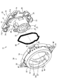
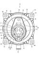
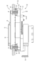
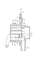
- FIG. 1 Perspective view of charging inlet as seen from diagonally forward Exploded perspective view showing components of charging inlet Front view of charging inlet Side view of charging inlet Partially cutaway side view showing the charging inlet fixed to the vehicle body Rear view of charging inlet Front view of inlet body Side view of inlet body Bottom view of inlet body AA line sectional view in FIG. BB sectional view in FIG.
- the charging inlet 10 in the present embodiment includes an inlet body 20, a holding plate (hereinafter referred to as “plate”) 50, and a seal member 80.
- the charging inlet 10 is attached in a posture facing obliquely upward with respect to the vehicle body 90.
- FIG. 5 for easy understanding, a state where the charging inlet 10 is attached to the body 90 in a horizontal posture is illustrated.
- the charging gun connected to the charger is connected to the charging inlet 10 so that the battery mounted on the vehicle is charged.
- the inlet main body 20 is made of a synthetic resin, and has a plate-like board part 21, a connector fitting part 22 provided in a form penetrating the board part 21 in the front-rear direction, and a board part 21 in the connector fitting part 22. And a tubular drain portion 23 provided so as to protrude downward from a portion protruding rearward. As shown in FIG. 7, a plurality of fixing portions 24 are provided on the outer peripheral side of the substrate portion 21. As shown in FIG. 6, the plate 50 is attached and fixed to the inlet body 20 by inserting bolts 24 ⁇ / b> A into the respective fixing portions 24 and tightening them into the plate 50.
- the connector fitting portion 22 includes a peripheral wall 25, a terminal accommodating portion 26 provided inside the peripheral wall 25, and a lock portion 34 provided on the outer peripheral upper surface of the peripheral wall 25.
- the terminal accommodating portion 26 has a circular block shape when viewed from the front, and a plurality of large and small cavities 27 and 28 are provided in the terminal accommodating portion 26 so as to penetrate in the front-rear direction.
- the large cavity 27 accommodates a large terminal (not shown) for large current
- the small cavity 28 accommodates a small terminal (not shown) for communication.
- two types of large and small drain holes 29 and 30 extending in an arc shape when viewed from the front are provided.
- the large drainage hole 29 is provided at the lower end of the terminal support wall 32 provided with the terminal insertion hole 31.
- a fitting space 33 in which a hood portion (not shown) provided in the charging gun is fitted is provided between the inner peripheral surface of the peripheral wall 25 and the outer peripheral surface of the terminal accommodating portion 26, a fitting space 33 in which a hood portion (not shown) provided in the charging gun is fitted is provided.
- the fitting space 33 communicates with the large cavity 27 and also communicates with the internal space of the drain portion 23. Therefore, the water that has entered the large cavity 27 flows into the fitting space 33 through the large drain hole 29, and is drained to the outside through the inner space of the drain part 23 from the fitting space 33.
- the small cavity 28 also has the same drainage structure as the large cavity 27, description thereof is omitted here.
- a pair of lock protection walls 35 are integrally provided on the left and right sides of the lock portion 34.
- the upper surface of the lock portion 34 is at a position lower than the upper end portion of the lock protection wall 35.
- the rear surface of the lock portion 34 is an engaging surface 36 having an undercut shape, and protrudes rearward from the rear end portion of the protective wall 35.
- a mounting groove 37 for mounting the seal member 80 is provided at a position surrounding the peripheral wall 25 and the lock portion 34.
- the lower half of the mounting groove 37 is configured by the outer peripheral surface of the peripheral wall 25, and the upper half of the mounting groove 37 is configured by the outer peripheral surface of the pedestal portion 38 connected to the rear end of the lock portion 34.
- the upper edge portion and the left and right side edge portions of the pedestal portion 38 have a substantially gate-shaped outer peripheral shape when viewed from the front, and the lower edge portion of the pedestal portion 38 has an arcuate concave shape along the outer peripheral upper surface of the peripheral wall 25. It is said that.
- a drain port 39 is provided on the outer peripheral side surface of the peripheral wall 25.
- the drainage port 39 has a rectangular shape that is long in the vertical direction when viewed from the side. Further, the drainage port 39 is formed by die cutting to the side when the inlet body 20 is molded.
- the front edge of the drain port 39 substantially coincides with the locking surface 36 of the lock portion 34 in the front-rear direction, and the rear edge of the drain port 39 is disposed at a position in contact with the front surface of the substrate unit 21.
- the drainage port 39 communicates with the fitting space 33 of the connector fitting portion 22. Therefore, the water that has entered the fitting space 33 from the drain port 39 through the outer peripheral surface of the peripheral wall 25 flows downward through the inner peripheral surface of the peripheral wall 25, and is drained to the outside through the internal space of the drain portion 23.
- the plate 50 is made of synthetic resin, and has a connector insertion hole 51 through which the connector fitting portion 22 is inserted, as shown in FIG.
- the connector insertion hole 51 is configured as a single hole in which the connector fitting portion 22 and the base portion 38 can be fitted and fitted.
- the connector insertion hole 51 is divided into a peripheral wall accommodating space 56 in which the peripheral wall 25 is accommodated and a lock portion accommodating space 57 in which the lock portion 34 is accommodated.
- a pair of left and right drain ports 39 are provided on the lower end of the lock portion accommodating space 57 on the outer peripheral surface of the peripheral wall 25, that is, on the outer peripheral side surface of the peripheral wall 25.
- the plate 50 projects outward from the intermediate wall 52 that forms the inner peripheral surface of the connector insertion hole 51, the annular outer cylindrical portion 53 provided around the intermediate wall 52, and the outer peripheral surface of the outer cylindrical portion 53. And a mounting portion 54 provided.
- the attachment portion 54 has a substantially square outer peripheral shape when viewed from the front, and four vehicle fastening portions 55 are provided at four corners of the attachment portion 54.
- a metal collar 40 is fixed to each vehicle fastening portion 55.
- the bolt 91 is fastened with the metal collar 90 in contact with the metal body 90 (metal touch), and the body 90 is placed between the head of the bolt 91 and the collar 40.
- the charging inlet 10 is attached and fixed to the body 90 by clamping.
- a pair of relief portions 21 ⁇ / b> A that allow the shaft portion of the bolt 91 to escape is provided at the upper corner portion of the substrate portion 21.
- This embodiment is configured as described above, and its operation will be described subsequently.
- the assembly and attachment work of the charging inlet 10 will be briefly described.
- a seal member 80 is fitted into the mounting groove 37 of the inlet body 20, and the plate 50 is assembled to the inlet body 20.
- the bolt 24A is inserted into the fixing portion 24, and the bolt 24A is fastened to the mounting portion 54 of the plate 50.
- the seal member 80 is sandwiched between the inlet body 20 and the plate 50, and water can be prevented from entering between the inlet body 20 and the plate 50.
- the charging inlet 10 is attached to the vehicle body 90.
- the mounting operation is performed by bringing the collar 40 of the vehicle fastening portion 55 of the plate 50 into contact with the body 90 and tightening the bolt 91.
- the charging inlet 10 since the charging inlet 10 is used outside the vehicle, rainwater or the like may fall on the charging inlet 10.
- the water adhering to the periphery of the lock portion 34 flows downward along the outer peripheral surface of the peripheral wall 25 toward the substrate portion 21 side (rear), and enters the fitting space 33 through the drainage port 39.
- the water that has entered the fitting space 33 flows down along the substrate portion 21 along the inner peripheral surface of the peripheral wall 25, and is drained outside the vehicle through the inside of the drain portion 23.
- the water that has entered the cavities 27 and 28 enters the fitting space 33 through the drain holes 29 and 30, flows downward along the board portion 21, and is drained outside the vehicle through the inside of the drain portion 23.
- the water adhering to the charging inlet 10 does not enter the interior of the vehicle (behind the board portion 21).
- the drainage port 39 is provided in the peripheral wall 25 of the connector fitting portion 22, it is not necessary to provide the drainage port behind the connector fitting portion 22. Further, since the peripheral wall accommodating space 56 and the lock portion accommodating space 57 are provided on the plate 50, the outer peripheral surface of the peripheral wall 25 faces the outside before the inlet main body 20 and the plate 50 are assembled, and the inlet main body 20 is molded. In this case, the drain port 39 can be provided by punching out sideways. Therefore, the number of parts can be reduced, and the assembly workability can be improved.
- the inlet main body 20 is configured to include a plate-shaped substrate portion 21 and a peripheral wall 25 provided so as to protrude from the substrate portion 21, and the drain port 39 is provided at a position in contact with the substrate portion 21. Also good.
- the charging inlet 10 is attached to the vehicle body 90 so as to face obliquely upward. Therefore, by providing the drain port 39 at a position in contact with the substrate unit 21, the water collected on the substrate unit 21 side can be used as it is. 39 can be drained.
- the drain port 39 may be configured to be provided at the lower end portion of the lock portion accommodating space 57 on the outer peripheral surface of the peripheral wall 25.
- the water that has entered the lock housing space 57 flows along the outer peripheral surface of the peripheral wall 25 and then flows down to the lower end of the lock housing space 57, and then flows into the peripheral wall housing space 56 through the drain port 39. Easy to do.
- the connector insertion hole 51 is exemplified by the peripheral wall accommodation space 56 and the lock portion accommodation space 57.
- the space constituting the connector insertion hole is other than the peripheral wall accommodation space 56 and the lock portion accommodation space 57. It is good also as what contains the space of.
- drain port 39 is provided at a position in contact with the substrate unit 21 in the above embodiment, the drain port may be provided at a position away from the substrate unit 21.
Landscapes
- Engineering & Computer Science (AREA)
- Power Engineering (AREA)
- Transportation (AREA)
- Mechanical Engineering (AREA)
- Connector Housings Or Holding Contact Members (AREA)
- Electric Propulsion And Braking For Vehicles (AREA)
- Charge And Discharge Circuits For Batteries Or The Like (AREA)
Abstract
本明細書によって開示された充電用インレット10は、コネクタ挿通孔51が設けられたプレート50と、コネクタ挿通孔51に挿通されるコネクタ嵌合部22を有し、プレート50に固定されたインレット本体20とを備えた充電用インレット10であって、コネクタ嵌合部22は、円筒状をなす周壁25と、周壁25の外周面に設けられたロック部34とを備えて構成され、コネクタ挿通孔51は、周壁25が収容された周壁収容空間56と、ロック部34が収容されたロック部収容空間57とを有し、周壁25には、ロック部収容空間57と周壁25内とを連通させる排水口39が設けられている構成とした。
Description
本明細書によって開示される技術は、充電用インレットに関する。
従来、充電器に接続された充電用コネクタが前方から嵌合可能な車両側コネクタとして、特開2015-103379号公報(下記特許文献1)に記載のものが知られている。車両側コネクタはハウジング本体を有し、このハウジング本体は、充電用コネクタが内部に嵌合するコネクタ嵌合部、充電用コネクタのロックアームが係止する被係止部を囲う略門形のロック嵌合部などを備えて構成されている。
上記の車両側コネクタにおいては、ロック嵌合部内に浸入した水をコネクタ嵌合部側に排水するための排水口が設けられている。排水口は、ロック嵌合部とコネクタ嵌合部を隔離する隔壁をまたぐようにして孔を設けることでロック嵌合部内とコネクタ嵌合部内とを連通させたものである。このような排水口は一般に、後方へ型抜きすることによって形成されているため、型抜き孔をゴム栓で閉じる必要がある。また、型抜き孔からゴム栓が抜けないように保持するゴム栓押さえが必要になるため、部品点数が増加し、組立作業が煩雑になる。
本明細書によって開示された充電用インレットは、コネクタ挿通孔が設けられたプレートと、前記コネクタ挿通孔に挿通されるコネクタ嵌合部を有し、前記プレートに固定されたインレット本体とを備えた充電用インレットであって、前記コネクタ嵌合部は、円筒状をなす周壁と、前記周壁の外周面に設けられたロック部とを備えて構成され、前記コネクタ挿通孔は、前記周壁が収容された周壁収容空間と、前記ロック部が収容されたロック部収容空間とを有し、前記周壁には、前記ロック部収容空間と前記周壁内とを連通させる排水口が設けられている構成とした。
このような構成によると、コネクタ嵌合部の周壁に排水口が設けられているため、コネクタ嵌合部の後方に排水口を設けなくてもよい。また、プレートに周壁収容空間とロック部収容空間とを設けたから、インレット本体とプレートを組み付ける前においては周壁の外周面が外部に臨んだ状態となり、インレット本体を成形する際に側方に型抜きすることで排水口を設けることができる。したがって、部品点数を削減し、もって組立作業性を向上させることができる。
本明細書によって開示される充電用インレットは、以下の構成としてもよい。
前記インレット本体は、板状をなす基板部と、前記基板部に突出して設けられた前記周壁とを備えて構成され、前記排水口は、前記基板部に接する位置に設けられている構成としてもよい。
一般に充電用インレットは車両のボディに対して斜め上を向いた姿勢で取り付けられるため、排水口を基板部に接する位置に設けることで基板部側に溜まった水をそのまま排水口から排水することができる。
前記インレット本体は、板状をなす基板部と、前記基板部に突出して設けられた前記周壁とを備えて構成され、前記排水口は、前記基板部に接する位置に設けられている構成としてもよい。
一般に充電用インレットは車両のボディに対して斜め上を向いた姿勢で取り付けられるため、排水口を基板部に接する位置に設けることで基板部側に溜まった水をそのまま排水口から排水することができる。
前記排水口は、前記周壁の外周面における前記ロック部収容空間の下端部に設けられている構成としてもよい。
このような構成によると、ロック部収容空間に浸入した水が周壁の外周面を伝ってロック部収容空間の下端部に流れ落ちた後、排水口を通って周壁収容空間に流れやすくできる。
このような構成によると、ロック部収容空間に浸入した水が周壁の外周面を伝ってロック部収容空間の下端部に流れ落ちた後、排水口を通って周壁収容空間に流れやすくできる。
本明細書によって開示される充電用インレットによれば、部品点数を削減し、もって組立作業性を向上させることができる。
<実施形態>
実施形態を図1から図11の図面を参照しながら説明する。本実施形態における充電用インレット10は、図1および図2に示すように、インレット本体20と、ホールディングプレート(以下「プレート」という)50と、シール部材80とを備えて構成されている。充電用インレット10は、車両のボディ90に対して斜め上を向いた姿勢で取り付けられる。ただし、図5においては理解を容易にするため、充電用インレット10を水平姿勢でボディ90に取り付けた状態を図示している。充電器に接続された充電用ガンが充電用インレット10に接続されることで車両に搭載されたバッテリへの充電が行われるようになっている。
実施形態を図1から図11の図面を参照しながら説明する。本実施形態における充電用インレット10は、図1および図2に示すように、インレット本体20と、ホールディングプレート(以下「プレート」という)50と、シール部材80とを備えて構成されている。充電用インレット10は、車両のボディ90に対して斜め上を向いた姿勢で取り付けられる。ただし、図5においては理解を容易にするため、充電用インレット10を水平姿勢でボディ90に取り付けた状態を図示している。充電器に接続された充電用ガンが充電用インレット10に接続されることで車両に搭載されたバッテリへの充電が行われるようになっている。
インレット本体20は合成樹脂製であって、板状をなす基板部21と、基板部21を前後方向に貫通する形態で設けられたコネクタ嵌合部22と、コネクタ嵌合部22における基板部21の後方に突出した部分から下方に突出して設けられた管状のドレイン部23とを備えて構成されている。図7に示すように、基板部21の外周側には、複数の固定部24が設けられている。図6に示すように、各固定部24にボルト24Aを挿入してプレート50に締め込むことでプレート50がインレット本体20に取り付けられて固定されている。
コネクタ嵌合部22は、図7に示すように、周壁25と、周壁25の内部に設けられた端子収容部26と、周壁25の外周上面に設けられたロック部34とを備えている。端子収容部26は、前方から見て円形のブロック状をなし、端子収容部26の内部には、大小2種類のキャビティ27、28が前後方向に貫通して複数設けられている。大きいキャビティ27には、大電流用の大型端子(図示せず)が収容され、小さいキャビティ28には、通信用の小型端子(図示せず)が収容される。各キャビティ27、28の下端部には、前方から見て弧状に延びる大小2種類の排水孔29、30が設けられている。
図10に示すように、大きい排水孔29は、端子挿通孔31が設けられた端子支持壁32の下端部に設けられている。一方、周壁25の内周面と端子収容部26の外周面との間には、充電用ガンに設けられたフード部(図示せず)が嵌合する嵌合空間33が設けられている。嵌合空間33は大きいキャビティ27に連通するとともに、ドレイン部23の内部空間にも連通している。したがって、大きいキャビティ27に浸入した水は、大きい排水孔29を通って嵌合空間33に流れ込み、嵌合空間33からドレイン部23の内部空間を通って外部に排水される。なお、小さいキャビティ28についても大きいキャビティ27と同様の排水構造を有しているため、ここでは説明を省略する。
図7に示すように、ロック部34の左右両側には、一対のロック保護壁35が一体に設けられている。図10に示すように、ロック部34の上面は、ロック保護壁35の上端部よりも低い位置にある。また、ロック部34の後面は、アンダーカット形状をなす係止面36とされ、保護壁35の後端部よりも後方に突出している。ロック部34の係止面36は、インレット本体20を成形する際、側方に型抜きすることによって形成されており、基板部21の後方に型抜き孔を設けて後方に型抜きする必要がないものとされている。
図7に示すように、周壁25およびロック部34を囲む位置には、シール部材80を装着するための装着溝37が周設されている。装着溝37の下半分は、周壁25の外周面によって構成され、装着溝37の上半分は、ロック部34の後端に連結された台座部38の外周面によって構成されている。台座部38の上縁部および左右の両側縁部は、前方から見て略門形の外周形状とされ、台座部38の下縁部は、周壁25の外周上面に沿った円弧状の凹形状とされている。
図8に示すように、周壁25の外周側面には、排水口39が設けられている。排水口39は、側方から見て上下に長い長方形状とされている。また、排水口39は、インレット本体20を成形する際、側方に型抜きすることによって形成されている。排水口39の前縁は、前後方向においてロック部34の係止面36とほぼ一致しており、排水口39の後縁は、基板部21の前面に接する位置に配されている。図11に示すように、排水口39は、コネクタ嵌合部22の嵌合空間33と連通している。したがって、周壁25の外周面を伝って排水口39から嵌合空間33に浸入した水は、周壁25の内周面を伝って下方に流れ、ドレイン部23の内部空間を通って外部に排水される。
プレート50は合成樹脂製であって、図2に示すように、コネクタ嵌合部22を挿通させるコネクタ挿通孔51を有している。図3に示すように、コネクタ挿通孔51は、コネクタ嵌合部22と台座部38が適合して嵌合可能な単一の孔として構成されている。コネクタ挿通孔51は詳細には、周壁25が収容された周壁収容空間56と、ロック部34が収容されたロック部収容空間57とに分けられる。前記した排水口39は、周壁25の外周面におけるロック部収容空間57の下端部、すなわち周壁25の外周側面に左右一対設けられている。インレット本体20とプレート50を組み付けると、台座部38および周壁25の外周面に嵌着されたシール部材80がコネクタ挿通孔51の内周面との間で挟持される。
プレート50は、コネクタ挿通孔51の内周面を構成する中間壁52と、中間壁52の周囲に設けられた円環状の外筒部53と、外筒部53の外周面から外方に張り出して設けられた取付部54とを備えて構成されている。取付部54は、図3に示すように、前方から見て略正方形の外周形状とされ、取付部54の四隅には、図示4つの車両締結部55が設けられている。各車両締結部55には、金属製のカラー40がそれぞれ固着されている。図5に示すように、金属製のボディ90に金属製のカラー40を当接させた状態(メタルタッチ)でボルト91を締結し、ボルト91の頭部とカラー40との間にボディ90を挟持することで充電用インレット10がボディ90に取り付けられて固定されている。なお、図1に示すように、基板部21の上端角部には、ボルト91の軸部を逃がす一対の逃がし部21Aが設けられている。
本実施形態は以上のような構成であって、続いてその作用を説明する。まず、充電用インレット10の組立および取付作業について簡単に説明する。インレット本体20の装着溝37にシール部材80を嵌着し、このインレット本体20にプレート50を組み付ける。固定部24にボルト24Aを挿入しプレート50の取付部54にボルト24Aを締結する。この結果、シール部材80がインレット本体20とプレート50の間に挟持され、インレット本体20とプレート50の間から水が浸入することを防止できる。その後、充電用インレット10を車両のボディ90に取り付ける。取り付け作業は、プレート50の車両締結部55のカラー40をボディ90に当接させ、ボルト91を締め込むことで行う。
通常、充電用インレット10は車外で使用されるため、雨水などが充電用インレット10に降り掛かるおそれがある。ロック部34の周辺に付着した水は、周壁25の外周面を伝って基板部21側(後方)に向かいつつ下方に流れ、排水口39を通って嵌合空間33に入る。嵌合空間33に入った水は、周壁25の内周面を伝って基板部21に沿うように下方に流れ、ドレイン部23の内部を通って車外に排水される。また、キャビティ27、28に浸入した水は、排水孔29、30を通って嵌合空間33に入り、基板部21に沿うように下方に流れ、ドレイン部23の内部を通って車外に排水される。このように、充電用インレット10に付着した水が車両の内部(基板部21よりも後方)に浸入することはないものとされている。
以上のように本実施形態によると、コネクタ嵌合部22の周壁25に排水口39が設けられているため、コネクタ嵌合部22の後方に排水口を設けなくてもよい。また、プレート50に周壁収容空間56とロック部収容空間57とを設けたから、インレット本体20とプレート50を組み付ける前においては周壁25の外周面が外部に臨んだ状態となり、インレット本体20を成形する際に側方に型抜きすることで排水口39を設けることができる。したがって、部品点数を削減し、もって組立作業性を向上させることができる。
インレット本体20は、板状をなす基板部21と、基板部21に突出して設けられた周壁25とを備えて構成され、排水口39は、基板部21に接する位置に設けられている構成としてもよい。
一般に充電用インレット10は車両のボディ90に対して斜め上を向いた姿勢で取り付けられるため、排水口39を基板部21に接する位置に設けることで基板部21側に溜まった水をそのまま排水口39から排水することができる。
排水口39は、周壁25の外周面におけるロック部収容空間57の下端部に設けられている構成としてもよい。
このような構成によると、ロック部収容空間57に浸入した水が周壁25の外周面を伝ってロック部収容空間57の下端部に流れ落ちた後、排水口39を通って周壁収容空間56に流れやすくできる。
<他の実施形態>
本明細書によって開示される技術は上記記述及び図面によって説明した実施形態に限定されるものではなく、例えば次のような種々の態様も含まれる。
(1)上記実施形態ではコネクタ挿通孔51が周壁収容空間56とロック部収容空間57とからなるものを例示したが、コネクタ挿通孔を構成する空間は周壁収容空間56とロック部収容空間57以外の空間を含むものとしてもよい。
本明細書によって開示される技術は上記記述及び図面によって説明した実施形態に限定されるものではなく、例えば次のような種々の態様も含まれる。
(1)上記実施形態ではコネクタ挿通孔51が周壁収容空間56とロック部収容空間57とからなるものを例示したが、コネクタ挿通孔を構成する空間は周壁収容空間56とロック部収容空間57以外の空間を含むものとしてもよい。
(2)上記実施形態では排水口39が基板部21に接する位置に設けられているものの、基板部21から離れた位置に排水口を設けてもよい。
(3)上記実施形態では左右一対の排水口39が周壁25の外周側面に設けられているものの、いずれか一方の外周側面に排水口39を1つだけ設けてもよい。
10…充電用インレット
20…インレット本体
21…基板部
22…コネクタ嵌合部
25…周壁
33…嵌合空間(周壁内)
34…ロック部
39…排水口
50…ホールディングプレート
51…コネクタ挿通孔
56…周壁収容空間
57…ロック部収容空間
20…インレット本体
21…基板部
22…コネクタ嵌合部
25…周壁
33…嵌合空間(周壁内)
34…ロック部
39…排水口
50…ホールディングプレート
51…コネクタ挿通孔
56…周壁収容空間
57…ロック部収容空間
Claims (3)
- コネクタ挿通孔が設けられたプレートと、
前記コネクタ挿通孔に挿通されるコネクタ嵌合部を有し、前記プレートに固定されたインレット本体とを備えた充電用インレットであって、
前記コネクタ嵌合部は、円筒状をなす周壁と、前記周壁の外周面に設けられたロック部とを備えて構成され、
前記コネクタ挿通孔は、前記周壁が収容された周壁収容空間と、前記ロック部が収容されたロック部収容空間とを有し、
前記周壁には、前記ロック部収容空間と前記周壁内とを連通させる排水口が設けられている充電用インレット。 - 前記インレット本体は、板状をなす基板部と、前記基板部に突出して設けられた前記周壁とを備えて構成され、前記排水口は、前記基板部に接する位置に設けられている請求項1に記載の充電用インレット。
- 前記排水口は、前記周壁の外周面における前記ロック部収容空間の下端部に設けられている請求項1または請求項2に記載の充電用インレット。
Priority Applications (3)
| Application Number | Priority Date | Filing Date | Title |
|---|---|---|---|
| US16/346,567 US10594071B2 (en) | 2016-11-21 | 2017-11-08 | Charging inlet with a drainage port in a peripheral wall |
| CN201780068726.0A CN109923740B (zh) | 2016-11-21 | 2017-11-08 | 充电用插入口 |
| DE112017005882.1T DE112017005882T5 (de) | 2016-11-21 | 2017-11-08 | Ladestecker |
Applications Claiming Priority (2)
| Application Number | Priority Date | Filing Date | Title |
|---|---|---|---|
| JP2016225850A JP2018085173A (ja) | 2016-11-21 | 2016-11-21 | 充電用インレット |
| JP2016-225850 | 2016-11-21 |
Publications (1)
| Publication Number | Publication Date |
|---|---|
| WO2018092646A1 true WO2018092646A1 (ja) | 2018-05-24 |
Family
ID=62146274
Family Applications (1)
| Application Number | Title | Priority Date | Filing Date |
|---|---|---|---|
| PCT/JP2017/040186 Ceased WO2018092646A1 (ja) | 2016-11-21 | 2017-11-08 | 充電用インレット |
Country Status (5)
| Country | Link |
|---|---|
| US (1) | US10594071B2 (ja) |
| JP (1) | JP2018085173A (ja) |
| CN (1) | CN109923740B (ja) |
| DE (1) | DE112017005882T5 (ja) |
| WO (1) | WO2018092646A1 (ja) |
Cited By (2)
| Publication number | Priority date | Publication date | Assignee | Title |
|---|---|---|---|---|
| CN110943331A (zh) * | 2018-07-27 | 2020-03-31 | 南京灵雀智能制造有限公司 | 一种高防护电动汽车快速充电用充电枪 |
| IT202100018752A1 (it) | 2021-07-15 | 2023-01-15 | Te Connectivity Italia Distribution Srl | Presa di ricarica dotata di un elemento bifunzionale per le funzioni di drenaggio e fissaggio |
Families Citing this family (5)
| Publication number | Priority date | Publication date | Assignee | Title |
|---|---|---|---|---|
| CN211265834U (zh) * | 2020-03-04 | 2020-08-14 | 东莞崧腾电子有限公司 | 高压连接器 |
| USD1014364S1 (en) | 2021-11-19 | 2024-02-13 | Polestar Performance Ab | Snow protector for vehicle charge port |
| US11993167B2 (en) * | 2021-11-19 | 2024-05-28 | Polestar Performance Ab | Snow protector for vehicle charge port |
| CN218569335U (zh) * | 2022-08-04 | 2023-03-03 | 宁波萌烨电器有限公司 | 防水插座 |
| BE1032529B1 (de) * | 2024-04-10 | 2025-11-10 | Phoenix Contact E Mobility Gmbh | Ladesteckverbinderteil eines Ladesystems zum elektrischen Aufladen eines Elektrofahrzeugs |
Citations (5)
| Publication number | Priority date | Publication date | Assignee | Title |
|---|---|---|---|---|
| JP2011175764A (ja) * | 2010-02-23 | 2011-09-08 | Toyota Motor Corp | インレット組立体 |
| JP2015225771A (ja) * | 2014-05-28 | 2015-12-14 | 住友電装株式会社 | 複合型充電用インレット |
| JP2016051673A (ja) * | 2014-09-02 | 2016-04-11 | 住友電装株式会社 | 車両用給電コネクタ |
| JP2016072003A (ja) * | 2014-09-29 | 2016-05-09 | 住友電装株式会社 | 車両用給電コネクタ |
| US20160248195A1 (en) * | 2013-09-24 | 2016-08-25 | Phoenix Contact E-Mobility Gmbh | Electrical plug connector part with a drain |
Family Cites Families (6)
| Publication number | Priority date | Publication date | Assignee | Title |
|---|---|---|---|---|
| JP5679191B2 (ja) * | 2011-04-05 | 2015-03-04 | 住友電装株式会社 | 車両側コネクタ |
| JP2014519685A (ja) * | 2011-05-31 | 2014-08-14 | コリア・エレクトリック・ターミナル・コーポレイション・リミテッド | 充電コネクタ掛止装置 |
| JP5981294B2 (ja) * | 2012-10-12 | 2016-08-31 | 矢崎総業株式会社 | 充電インレット装置 |
| JP6032495B2 (ja) | 2013-11-25 | 2016-11-30 | 住友電装株式会社 | 車両側コネクタ |
| JP5898708B2 (ja) * | 2014-01-30 | 2016-04-06 | 京楽産業.株式会社 | 遊技機 |
| JP2016046180A (ja) * | 2014-08-26 | 2016-04-04 | 住友電装株式会社 | 充電用インレット |
-
2016
- 2016-11-21 JP JP2016225850A patent/JP2018085173A/ja active Pending
-
2017
- 2017-11-08 CN CN201780068726.0A patent/CN109923740B/zh not_active Expired - Fee Related
- 2017-11-08 US US16/346,567 patent/US10594071B2/en not_active Expired - Fee Related
- 2017-11-08 DE DE112017005882.1T patent/DE112017005882T5/de not_active Withdrawn
- 2017-11-08 WO PCT/JP2017/040186 patent/WO2018092646A1/ja not_active Ceased
Patent Citations (5)
| Publication number | Priority date | Publication date | Assignee | Title |
|---|---|---|---|---|
| JP2011175764A (ja) * | 2010-02-23 | 2011-09-08 | Toyota Motor Corp | インレット組立体 |
| US20160248195A1 (en) * | 2013-09-24 | 2016-08-25 | Phoenix Contact E-Mobility Gmbh | Electrical plug connector part with a drain |
| JP2015225771A (ja) * | 2014-05-28 | 2015-12-14 | 住友電装株式会社 | 複合型充電用インレット |
| JP2016051673A (ja) * | 2014-09-02 | 2016-04-11 | 住友電装株式会社 | 車両用給電コネクタ |
| JP2016072003A (ja) * | 2014-09-29 | 2016-05-09 | 住友電装株式会社 | 車両用給電コネクタ |
Cited By (7)
| Publication number | Priority date | Publication date | Assignee | Title |
|---|---|---|---|---|
| CN110943331A (zh) * | 2018-07-27 | 2020-03-31 | 南京灵雀智能制造有限公司 | 一种高防护电动汽车快速充电用充电枪 |
| CN110943331B (zh) * | 2018-07-27 | 2021-02-05 | 南京灵雀智能制造有限公司 | 一种高防护电动汽车快速充电用充电枪 |
| IT202100018752A1 (it) | 2021-07-15 | 2023-01-15 | Te Connectivity Italia Distribution Srl | Presa di ricarica dotata di un elemento bifunzionale per le funzioni di drenaggio e fissaggio |
| EP4120484A1 (en) | 2021-07-15 | 2023-01-18 | TE Connectivity Italia Distribution S.r.l. | Charging socket provided with a dual-functional feature for drainage and fixing functions |
| JP2023014020A (ja) * | 2021-07-15 | 2023-01-26 | ティーイー コネクティビティ イタリア ディストリビューション エッセ エッルレ エッレ | 排水機能および固定機能のための二重機能機構を備える充電ソケット |
| JP7466591B2 (ja) | 2021-07-15 | 2024-04-12 | ティーイー コネクティビティ イタリア ディストリビューション エッセ エッルレ エッレ | 排水機能および固定機能のための二重機能機構を備える充電ソケット |
| US12296699B2 (en) | 2021-07-15 | 2025-05-13 | TE Connectivity Italia Distribution S.r.l. | Charging socket provided with a dual-functional feature for drainage and fixing functions |
Also Published As
| Publication number | Publication date |
|---|---|
| CN109923740B (zh) | 2020-08-11 |
| DE112017005882T5 (de) | 2019-08-08 |
| US20190267749A1 (en) | 2019-08-29 |
| JP2018085173A (ja) | 2018-05-31 |
| US10594071B2 (en) | 2020-03-17 |
| CN109923740A (zh) | 2019-06-21 |
Similar Documents
| Publication | Publication Date | Title |
|---|---|---|
| WO2018092646A1 (ja) | 充電用インレット | |
| JP5673309B2 (ja) | 車両側コネクタ | |
| WO2018092631A1 (ja) | 充電用インレット | |
| JP5644657B2 (ja) | 車載用電気機器のシールカバー | |
| KR101470276B1 (ko) | 차량용 방수 커넥터 | |
| JP4536444B2 (ja) | 機器用コネクタ | |
| JP2016046180A (ja) | 充電用インレット | |
| JP2014232686A (ja) | 端子台 | |
| JPWO2014199576A1 (ja) | バッテリーセンサの位置決め具、これを備えるバッテリーセンサアッセンブリ、及びバッテリーセンサ | |
| JP6287496B2 (ja) | 鉛蓄電池及びこれに設けられた着脱部材 | |
| KR101926934B1 (ko) | 고전압 정션블록의 장착구조 | |
| JP2016072003A (ja) | 車両用給電コネクタ | |
| JP4222219B2 (ja) | 自動車用電気接続箱 | |
| JP6672995B2 (ja) | 防水コネクタ | |
| JP6451996B2 (ja) | コネクタ | |
| JP5660413B2 (ja) | 車両側コネクタ | |
| CN211376724U (zh) | 电池箱 | |
| JP2016192287A (ja) | コネクタ | |
| JP2009106049A (ja) | ケーブル保持構造 | |
| JP2012089297A (ja) | 機器用コネクタ | |
| JP6601310B2 (ja) | 車両側コネクタ | |
| JP2011120314A (ja) | 配線引込口装置 | |
| JP2017045635A (ja) | シール付きリテーナ | |
| JP2025058555A (ja) | コネクタユニット | |
| KR100559424B1 (ko) | 차량의 아웃사이드 미러 어셈블리 |
Legal Events
| Date | Code | Title | Description |
|---|---|---|---|
| 121 | Ep: the epo has been informed by wipo that ep was designated in this application |
Ref document number: 17872354 Country of ref document: EP Kind code of ref document: A1 |
|
| 122 | Ep: pct application non-entry in european phase |
Ref document number: 17872354 Country of ref document: EP Kind code of ref document: A1 |