WO2018092357A1 - 空気調和制御装置及び空気調和制御方法 - Google Patents
空気調和制御装置及び空気調和制御方法 Download PDFInfo
- Publication number
- WO2018092357A1 WO2018092357A1 PCT/JP2017/027502 JP2017027502W WO2018092357A1 WO 2018092357 A1 WO2018092357 A1 WO 2018092357A1 JP 2017027502 W JP2017027502 W JP 2017027502W WO 2018092357 A1 WO2018092357 A1 WO 2018092357A1
- Authority
- WO
- WIPO (PCT)
- Prior art keywords
- room temperature
- temperature
- power consumption
- air
- refrigerant
- Prior art date
Links
Images


Classifications
-
- F—MECHANICAL ENGINEERING; LIGHTING; HEATING; WEAPONS; BLASTING
- F24—HEATING; RANGES; VENTILATING
- F24F—AIR-CONDITIONING; AIR-HUMIDIFICATION; VENTILATION; USE OF AIR CURRENTS FOR SCREENING
- F24F11/00—Control or safety arrangements
- F24F11/30—Control or safety arrangements for purposes related to the operation of the system, e.g. for safety or monitoring
- F24F11/46—Improving electric energy efficiency or saving
-
- F—MECHANICAL ENGINEERING; LIGHTING; HEATING; WEAPONS; BLASTING
- F24—HEATING; RANGES; VENTILATING
- F24F—AIR-CONDITIONING; AIR-HUMIDIFICATION; VENTILATION; USE OF AIR CURRENTS FOR SCREENING
- F24F11/00—Control or safety arrangements
- F24F11/50—Control or safety arrangements characterised by user interfaces or communication
- F24F11/52—Indication arrangements, e.g. displays
-
- F—MECHANICAL ENGINEERING; LIGHTING; HEATING; WEAPONS; BLASTING
- F24—HEATING; RANGES; VENTILATING
- F24F—AIR-CONDITIONING; AIR-HUMIDIFICATION; VENTILATION; USE OF AIR CURRENTS FOR SCREENING
- F24F11/00—Control or safety arrangements
- F24F11/62—Control or safety arrangements characterised by the type of control or by internal processing, e.g. using fuzzy logic, adaptive control or estimation of values
- F24F11/63—Electronic processing
- F24F11/64—Electronic processing using pre-stored data
-
- F—MECHANICAL ENGINEERING; LIGHTING; HEATING; WEAPONS; BLASTING
- F24—HEATING; RANGES; VENTILATING
- F24F—AIR-CONDITIONING; AIR-HUMIDIFICATION; VENTILATION; USE OF AIR CURRENTS FOR SCREENING
- F24F11/00—Control or safety arrangements
- F24F11/62—Control or safety arrangements characterised by the type of control or by internal processing, e.g. using fuzzy logic, adaptive control or estimation of values
- F24F11/63—Electronic processing
- F24F11/65—Electronic processing for selecting an operating mode
- F24F11/67—Switching between heating and cooling modes
-
- F—MECHANICAL ENGINEERING; LIGHTING; HEATING; WEAPONS; BLASTING
- F24—HEATING; RANGES; VENTILATING
- F24F—AIR-CONDITIONING; AIR-HUMIDIFICATION; VENTILATION; USE OF AIR CURRENTS FOR SCREENING
- F24F11/00—Control or safety arrangements
- F24F11/70—Control systems characterised by their outputs; Constructional details thereof
- F24F11/80—Control systems characterised by their outputs; Constructional details thereof for controlling the temperature of the supplied air
- F24F11/83—Control systems characterised by their outputs; Constructional details thereof for controlling the temperature of the supplied air by controlling the supply of heat-exchange fluids to heat-exchangers
-
- G—PHYSICS
- G05—CONTROLLING; REGULATING
- G05B—CONTROL OR REGULATING SYSTEMS IN GENERAL; FUNCTIONAL ELEMENTS OF SUCH SYSTEMS; MONITORING OR TESTING ARRANGEMENTS FOR SUCH SYSTEMS OR ELEMENTS
- G05B13/00—Adaptive control systems, i.e. systems automatically adjusting themselves to have a performance which is optimum according to some preassigned criterion
- G05B13/02—Adaptive control systems, i.e. systems automatically adjusting themselves to have a performance which is optimum according to some preassigned criterion electric
- G05B13/0205—Adaptive control systems, i.e. systems automatically adjusting themselves to have a performance which is optimum according to some preassigned criterion electric not using a model or a simulator of the controlled system
- G05B13/026—Adaptive control systems, i.e. systems automatically adjusting themselves to have a performance which is optimum according to some preassigned criterion electric not using a model or a simulator of the controlled system using a predictor
-
- F—MECHANICAL ENGINEERING; LIGHTING; HEATING; WEAPONS; BLASTING
- F24—HEATING; RANGES; VENTILATING
- F24F—AIR-CONDITIONING; AIR-HUMIDIFICATION; VENTILATION; USE OF AIR CURRENTS FOR SCREENING
- F24F2110/00—Control inputs relating to air properties
- F24F2110/10—Temperature
-
- F—MECHANICAL ENGINEERING; LIGHTING; HEATING; WEAPONS; BLASTING
- F24—HEATING; RANGES; VENTILATING
- F24F—AIR-CONDITIONING; AIR-HUMIDIFICATION; VENTILATION; USE OF AIR CURRENTS FOR SCREENING
- F24F2110/00—Control inputs relating to air properties
- F24F2110/20—Humidity
-
- F—MECHANICAL ENGINEERING; LIGHTING; HEATING; WEAPONS; BLASTING
- F24—HEATING; RANGES; VENTILATING
- F24F—AIR-CONDITIONING; AIR-HUMIDIFICATION; VENTILATION; USE OF AIR CURRENTS FOR SCREENING
- F24F2140/00—Control inputs relating to system states
- F24F2140/20—Heat-exchange fluid temperature
-
- F—MECHANICAL ENGINEERING; LIGHTING; HEATING; WEAPONS; BLASTING
- F24—HEATING; RANGES; VENTILATING
- F24F—AIR-CONDITIONING; AIR-HUMIDIFICATION; VENTILATION; USE OF AIR CURRENTS FOR SCREENING
- F24F2140/00—Control inputs relating to system states
- F24F2140/60—Energy consumption
Definitions
- the present invention relates to an air conditioner control apparatus and an air conditioner control method for a heat pump type air conditioner.
- the outside air condition and the indoor condition are measured, and the evaporation temperature, the condensation temperature, and the COP (Coefficient) of the air conditioner in this air state are measured.
- the relationship of Of Performance (coefficient of performance) is obtained, and the air conditioner is operated using the evaporation temperature and condensation temperature that can respond to the load and give the maximum COP (for example, Patent Document 2) .
- the present invention has been made in order to solve the above-described problems, and the air that is operated by reflecting the set room temperature desired by the user in the air conditioner without increasing the power consumption of the air conditioner. It aims at obtaining the air conditioning control apparatus and the air conditioning control method of a harmony machine.
- the air conditioning control device inputs the second set room temperature changed from the first set room temperature of the air conditioner including the refrigeration cycle, and the refrigerant temperature as a parameter, so that the room according to the second set room temperature is used.
- the air conditioning control device of the present invention inputs a set candidate room temperature of an air conditioner including a refrigeration cycle and a refrigerant temperature that is a parameter, thereby estimating a room humidity and a latent heat load due to the set candidate room temperature.
- a refrigeration cycle estimation unit that estimates the power consumption due to the setting candidate room temperature by inputting the outside air temperature, the refrigerant temperature, the indoor humidity, and the latent heat load, and the indoor humidity estimation unit and the refrigeration cycle estimation unit that change the refrigerant temperature If the power consumption estimated by the refrigeration cycle estimator matches the power consumption due to the current set room temperature of the air conditioner by repeating the estimation, the refrigerant temperature calculation for obtaining the refrigerant temperature when it matches the set candidate room temperature Unit and the candidate temperature when the power consumption obtained by the refrigerant temperature calculation unit matches.
- An air conditioning control device being characterized in that a setting candidate storage display unit for displaying.
- the air conditioning control method of the present invention inputs the second set room temperature, which is changed from the first set room temperature of the air conditioner including the refrigeration cycle, and the refrigerant temperature which is a parameter, so that the second set room temperature is obtained.
- An indoor humidity estimation step for estimating the indoor humidity and latent heat load by the refrigeration cycle estimating step for estimating the power consumption at the second set room temperature by inputting the outside air temperature, the refrigerant temperature, the indoor humidity and the latent heat load;
- An air-conditioning control method comprising: a refrigerant temperature calculation step for instructing an air conditioner to set a refrigerant temperature at the time of coincidence.
- the air conditioning control method of the present invention is configured to estimate the indoor humidity and the latent heat load due to the set candidate room temperature by inputting the set candidate room temperature of the air conditioner including the refrigeration cycle and the refrigerant temperature as a parameter.
- the power consumption estimated by the refrigeration cycle estimation step matches the power consumption due to the current set room temperature of the air conditioner, the refrigerant temperature calculation for obtaining the refrigerant temperature when it matches the set candidate room temperature If the power consumption obtained in the step and the refrigerant temperature calculation step match,
- the product is an air conditioning control method, characterized in that a setting candidate storage display step of displaying a setting candidate room temperature when the power is matched.
- the air conditioning system can be operated at a set room temperature desired by the user without changing the power consumption of the air conditioning system.
- FIG. 1 is a schematic diagram showing a space into which an air conditioning system according to Embodiment 1 of the present invention is introduced.
- FIG. 2 is a schematic diagram of the air conditioning system according to Embodiment 1 of the present invention.
- FIG. 3 is a schematic diagram of the refrigerant circuit of the air conditioner according to Embodiment 1 of the present invention.
- FIG. 4 is a schematic diagram of a ventilation device according to Embodiment 1 of the present invention.
- FIG. 5 is a diagram showing indoor zone division according to Embodiment 1 of the present invention.
- FIG. 6 is a diagram showing an example of load types and zoning classifications according to Embodiment 1 of the present invention.
- FIG. 1 is a schematic diagram showing a space into which an air conditioning system according to Embodiment 1 of the present invention is introduced.
- FIG. 2 is a schematic diagram of the air conditioning system according to Embodiment 1 of the present invention.
- FIG. 3 is a schematic diagram of the refrigerant
- FIG. 7 is a configuration diagram of the air-conditioning control apparatus according to Embodiment 1 of the present invention.
- FIG. 8 is a configuration diagram of the air-conditioning control apparatus according to Embodiment 1 of the present invention.
- FIG. 9 is a flowchart for estimating the number of people in the room according to the first embodiment of the present invention.
- FIG. 10 is a diagram showing a human load according to the first embodiment of the present invention.
- FIG. 11 is a flowchart of internal heat generation estimation according to Embodiment 1 of the present invention.
- FIG. 12 is a flowchart of power consumption estimation according to Embodiment 1 of the present invention.
- FIG. 13 is a diagram for estimating power consumption using the table according to the first embodiment of the present invention.
- FIG. 14 is a flowchart of the air-conditioning control apparatus according to Embodiment 1 of the present invention.
- FIG. 15 is a flowchart of the indoor humidity estimation unit according to Embodiment 1 of the present invention.
- FIG. 16 is a flowchart of the refrigeration cycle estimation unit according to Embodiment 1 of the present invention.
- FIG. 17 is a configuration diagram of an air-conditioning control apparatus according to Embodiment 2 of the present invention.
- FIG. 18 is a configuration diagram of an air-conditioning control apparatus according to Embodiment 2 of the present invention.
- FIG. 19 is a diagram illustrating a configuration example of a notification unit according to the second embodiment of the present invention.
- FIG. 20 is a configuration diagram of an air-conditioning control apparatus according to Embodiment 3 of the present invention.
- FIG. 21 is a configuration diagram of an air-conditioning control apparatus according to Embodiment 3 of the present invention.
- FIG. 22 is a diagram showing an example of the setting candidate accumulation display unit according to the third embodiment of the present invention.
- FIG. 23 is a diagram illustrating an example of an air-conditioning control apparatus according to Embodiment 4 of the present invention.
- FIG. FIG. 1 is a schematic diagram showing a space into which an air conditioning system according to Embodiment 1 of the present invention is introduced.
- the air conditioning system main devices such as the indoor unit 11 and the outdoor unit 12, the ventilation device 13, and the air conditioning control device 102 are shown.
- a ventilation device 13 is introduced in an air conditioning system that assumes a person, but the present invention can be applied even when the ventilation device 13 is not provided.
- the indoor unit 11 may be any type such as a ceiling-embedded type, a ceiling-suspended type, a wall-mounted type, and a floor-standing type.
- the outdoor unit 12 may be installed on the roof as shown in FIG. 1 or may be installed on a balcony or the like installed on the outdoor side of the vertical wall 15.
- the indoor unit 11 and the outdoor unit 12 may be installed as separate housings and connected by piping, or may be installed through the wall 15 and the window 14 as the same housing. It may be a thing.
- the ventilator 13 is installed near the ceiling or near the ceiling surface of the vertical wall 15 to supply the introduced outside air to the space.
- the introduced outside air may be immediately supplied to the space from the place where the ventilator 13 is installed, or may be supplied to the room through a duct provided on the ceiling surface of each position of the room through the duct.
- the introduced outside air outlet may be of the same type as the outlet of the indoor unit 11.
- the space is used as an office.
- the wall 15 is provided with a window 14, which introduces natural light and prevents a closed impression.
- the floor is provided with a desk and an OA device 16 installed on the desk, and facilities for office work are provided.
- An illumination 17 is installed on the ceiling surface to ensure the illuminance at hand of the operator as necessary.
- a human 18 is present in the space and is performing office work.
- the office is used as an example in the description of the first embodiment, the space to which the present technology is applied is not limited to the office, and can be similarly applied to schools, hospitals, commercial facilities, and the like.
- the air conditioning system can be controlled by using the air conditioning control device 102, and the human 18 can command the set room temperature via the air conditioning control device 102 in addition to starting and stopping the air conditioning system as necessary. It can be reflected in the system.
- sensors are installed for grasping the outdoor temperature and humidity and the usage status of the space.
- a temperature and humidity sensor 19 for measuring the temperature and humidity of the outside air is installed on the roof.
- a power meter 20 is installed in the outdoor unit 12, the OA device 16, and the illumination 17, and the power consumption of each device can be measured.
- the wattmeter 20 may be anything as long as it can obtain the power consumption of each device.
- the power may be estimated and output using a measurement value of a sensor provided in the air conditioner in advance for controlling the air conditioner.
- the power consumption of the OA device 16 and the illumination 17 does not need to be measured separately, and a method in which the total value is measured may be used.
- the total value of the power consumption of both devices may be measured with a distribution board.
- FIG. 2 is a schematic diagram of the air conditioning system according to Embodiment 1 of the present invention.
- the air conditioning system includes, for example, an air conditioner 10, a ventilation device 13, and an air conditioning control device 102.
- the air conditioner 10 includes three indoor units 11 and one outdoor unit 12. The indoor unit 11 is installed indoors, and the outdoor unit 12 is installed outdoors.
- the outdoor unit 12 can exchange refrigerant with the indoor unit 11 via the refrigerant pipe 103. While the ventilator 13 can take outdoor air into the room and exhaust the indoor air to the outside, it is not essential for the implementation of the present invention.
- the air conditioning control device 102 allows the user of the air conditioning system to input a set room temperature.
- the indoor unit 11, the outdoor unit 12, the ventilation device 13, and the air conditioning control device 102 are connected by a transmission line 104 indicated by a dotted line.
- the air conditioning control device 102 collects operation data such as measured values, start and stop of the sensors in the indoor unit 11, the outdoor unit 12, and the ventilation device 13 through a transmission line 104 in a storage unit that is a storage medium, You can record.
- the transmission line 104 can transmit a control command issued from the air conditioning control device 102 to the indoor unit 11 and the outdoor unit 12.
- the air conditioner 10 When the user inputs the set room temperature to the air conditioning control device 102 and the air conditioning system starts operation, the air conditioner 10 operates so that the room temperature approaches the set room temperature.
- FIG. 3 is a schematic diagram of a refrigerant circuit of the air conditioner 10 according to Embodiment 1 of the present invention.
- the air conditioner 10 includes a compressor 2, an expansion valve 3, an indoor heat exchanger 4, and an outdoor heat exchanger 6, which are connected by a refrigerant pipe 103.
- the indoor heat exchanger 4 includes an indoor fan 5, and the outdoor heat exchanger 6 includes an outdoor fan 7. Furthermore, the efficiency of heat exchange is improved by sending air to the heat exchanger during operation of the air conditioner 10.
- the air conditioner 10 is a heat pump type.
- the air conditioner 10 compresses the refrigerant by the compressor 2 during cooling, and the refrigerant flows into the outdoor heat exchanger 6 in a high-temperature and high-pressure state, so that the refrigerant temperature is lowered by exchanging heat with the outdoor air. Thereafter, the refrigerant flows into the indoor unit 11 through the refrigerant pipe 103.
- the refrigerant that has flowed into the indoor unit 11 is decompressed by the expansion valve 3, flows into the indoor heat exchanger 4 in a low-temperature and low-pressure state, and heat-exchanges with indoor air, thereby increasing the refrigerant temperature.
- the indoor air is cooled by taking heat away from the refrigerant and returned to the room.
- the refrigerant returns to the compressor 2 again and cools the room by repeating the above cycle.
- the air conditioner 10 flows in the order of the compressor 2, the outdoor heat exchanger 6, the expansion valve 3, and the indoor heat exchanger 4 during cooling, but the compressor 2 includes a four-way valve on the refrigerant circuit.
- the indoor heat exchanger 4, the expansion valve 3, and the outdoor heat exchanger 6 may be flowed in this order to perform heating.
- FIG. 4 is a schematic diagram of the ventilation device 13 according to Embodiment 1 of the present invention.
- the ventilation device 13 includes an air supply fan 131 for introducing outdoor air into the room as indicated by a dashed line arrow, and an exhaust fan 132 for exhausting the indoor air to the outside as indicated by a dotted line arrow. And a total heat exchanger 133 for exchanging total heat between outdoor air and indoor air. In addition to the total heat exchanger 133, an air filter or a humidification unit may be further provided. The heat exchange efficiency of the ventilator 13 is required including the air filter and the humidification unit.
- FIG. 5 is a diagram showing indoor zone division according to Embodiment 1 of the present invention. More specifically, the room 101, which is an overhead view of the room in FIG. 2, is divided into a perimeter 101a that is strongly influenced by the outside and an interior 101b that is relatively less susceptible to the outside. Such distinction of the location of the room 101 is called zoning.
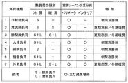
- FIG. 6 is a diagram showing examples of load types and zoning classifications according to Embodiment 1 of the present invention.
- the interior 101b mainly includes a human body load, a lighting load, a device load, and an outside air load accompanying the introduction of outside air for ventilation.
- the perimeter 101a has a heat load for processing a solar heat load, a once-through heat load, and a crevice wind load in addition to the heat load processed by the interior 101b. From this, it can be seen that the perimeter 101a tends to have a larger thermal load than the interior 101b.
- the air conditioner 10 having a larger capacity than the interior 101b is installed in the perimeter 101a, and the perimeter 101a generally corresponds to a larger heat load than the interior 101b.
- the once-through heat load, the solar heat load, and the interstitial wind load that enter from the outside are processed by the air conditioner 10 of the perimeter 101a.
- the operation data of the air conditioner 10 in the interior 101b is analyzed, so that the heat load currently processed by the air conditioner 10 is analyzed.
- the latent heat and sensible heat are separately estimated for each type of load. Even in the case of the perimeter 101a, it is possible to cope with this problem by applying a technique for estimating the solar heat load, the once-through heat load, and the draft air load.
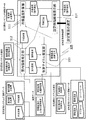
- FIG. 7 and 8 are configuration diagrams of the air-conditioning control apparatus 102 according to Embodiment 1 of the present invention.
- the difference between FIG. 7 and FIG. 8 is that the storage unit 115 as a storage medium is provided outside the air conditioning control apparatus 102, and FIG. 8 is provided outside.
- the air conditioning control apparatus 102 includes at least a refrigerant temperature calculation unit 111, an indoor humidity estimation unit 112, and a refrigeration cycle estimation unit 113.
- the configuration diagram of the air conditioning control device 102 in FIG. 7 all the data obtained from the outside or the specifications of the system are all placed outside, and the minimum necessary configuration of the air conditioning control device 102 is shown.
- the outside air temperature, the power consumption before the change, and the set room temperature after the change, which are operation data of the air conditioning system, are essential information for the air conditioning control device 102.
- the configuration diagram of the air conditioning control device 102 in FIG. 8 shows a configuration in which all data or system specifications that can be obtained from the outside are stored in the storage unit 115.
- the storage unit 115 stores the latent heat load and sensible heat load of the human body at the changed set room temperature as the load data, and the specifications of the air conditioning system include the heat exchange efficiency of the outdoor unit 12 and the efficiency formula of the compressor 2.
- the heat exchange efficiency of the indoor unit 11 and the heat exchange efficiency of the ventilator 13 are stored, and the operation data of the air conditioning system is the power consumption at the set room temperature before the change, the set room temperature after the change, the air volume of the indoor unit 11,
- the air volume, the outside air temperature and the outside air humidity, the condensation temperature and the evaporation temperature, the subcool (supercooling degree), and the superheat (superheating degree) of the ventilation device 13 can be stored.
- the storage unit 115 is used. However, for example, the power consumption due to the set room temperature before the change can be obtained directly from the outside without being stored in the storage unit 115. It is not essential. Further, the heat exchange efficiency of the indoor unit 11 and the heat exchange efficiency of the ventilation device 13 may be stored in the indoor humidity estimation unit 112 without being stored in the storage unit 115. Further, the heat exchange efficiency of the outdoor unit 12 and the efficiency equation of the compressor 2 may be stored in the refrigeration cycle estimation unit 113 without being stored in the storage unit 115. The changed set room temperature, the air volume of the indoor unit 11, the air volume of the ventilator 13, the outside air temperature, and the outside air humidity can be directly obtained from the outside without being stored in the storage unit 115.
- the air conditioning control of FIG. 7 is actually performed except for the outside air temperature, the power consumption due to the set room temperature before the change, and the set room temperature after the change.
- the configuration of the device 102 is the minimum necessary configuration. Further, even when a configuration including the storage unit 115 is assumed, it is apparent that there is no problem if the storage unit 115 does not have all the data or specifications described here.
- the information shown in the specifications of the air conditioning system, the operation data of the air conditioning system, and the load data are used.
- it is indicated by the specifications of the air conditioning system, the operation data of the air conditioning system, and the load data. It is possible to substitute without using a part of the information.
- the air conditioning control device 102 is connected to the ventilating device 13 and the air conditioner 10 through a communication line, and stores the operation data of the air conditioning system in the storage unit 115, or air conditioning the refrigerant temperature (evaporation temperature) or the set room temperature.
- the machine 10 can be commanded.
- the operation data of the air conditioning system includes, for example, the set room temperature before and after the change, the air volume of the indoor unit 11, the air volume of the ventilator 13, the outside air temperature, and the outside air humidity.
- the operation data of these air conditioning systems can also be stored in the storage unit 115.
- the air conditioning control device 102 can store the temperature and humidity of the outside air in the storage unit 115 via the temperature / humidity sensor 19 installed outdoors.
- the temperature / humidity sensor 19 may be installed independently, or may be provided in the ventilation device 13 or the outdoor unit 12 in advance.
- the air conditioning control device 102 is connected to the occupancy sensor 21, and the number of occupants can be stored in the storage unit 115. If the time series pattern of the number of people in the room is known in advance, the time series pattern may be stored in advance without using the in-room sensor 21. Furthermore, the number of people in the room may be estimated from the specifications of the air conditioning system, the operation data of the air conditioning system, and the outside air temperature / humidity without providing the room presence sensor 21. A specific example will be described below.
- FIG. 9 is a flowchart for estimating the number of people in the room according to the first embodiment of the present invention.
- the total heat treatment amount Q of the air conditioner 10 is calculated from the refrigerant side of the air conditioner 10 (ST101).
- the total heat treatment amount Q can be calculated from the flow rate of the refrigerant flowing through each indoor unit 11 and the change in enthalpy before and after passing through each indoor unit 11.
- indoor units 11 If there are a plurality of indoor units 11, they may be calculated separately and summed up. Hereinafter, since the calculation formula when there is one indoor unit 11 is shown, when there are a plurality of units, the values may be calculated for each indoor unit 11 and totaled.
- the sensible heat treatment amount Q is of the air conditioner 10 is calculated from the air side (ST102).
- Q is : sensible heat treatment amount [kW] of indoor unit 11, ⁇ a : air density [kg / m 3 ], C p : air specific heat [kJ / kgK], V a : air volume of indoor unit 11 [m 3 / s ], ⁇ aT : temperature exchange efficiency of the indoor unit 11, ⁇ : operating rate of the indoor unit 11, T in : intake air temperature [K], T hex : heat exchanger surface temperature [K]
- SHF Sensible Heat Factor
- SHF Q is / Q
- SHF sensible heat treatment ratio
- Q total heat treatment amount of the air conditioner 10 [kW]
- SHF can also be expressed as follows using an equation for calculating the amount of sensible heat treatment from the air side and an equation for calculating the amount of latent heat treatment.
- SHF (T in ⁇ T hex ) / (I in ⁇ I hex )
- SHF sensible heat treatment ratio
- T in intake air temperature [K]
- T hex heat exchanger surface temperature [K]
- I in indoor air enthalpy [kJ / kgK]
- I hex heat exchanger Enthalpy of saturated air at surface temperature [kJ / kgK]
- the enthalpy of the room 101 can be calculated (ST104). Now that the temperature and enthalpy of the room 101 are known, the sensible heat load Q vs and the latent heat load Q vl of the ventilator 13 can be calculated (ST105).
- the latent heat load Q pl of the human body can be calculated (ST106).
- Q pl Q l -Q vl
- Q pl Latent heat load [kW] of human body
- Q l Process latent heat amount [kW] of indoor unit 11
- Q vl Latent heat load [kW] of ventilator 13
- FIG. 10 is a diagram showing a human body load according to the first embodiment of the present invention. More specifically, it is an example in which the generated load of the human body is shown separately for sensible heat and latent heat for each temperature and activity. For example, the number of people in the room can be estimated by calculating the latent heat load per person using this table and dividing the latent heat load per person (ST107).
- N p Q pl / Q pl_1 N p : number of people in the room , Q ps — 1: latent heat load per person [kW]
- the number of people in the room may be estimated from the specifications of the air conditioning system, the operation data of the air conditioning system, and the outside temperature and humidity without using the room presence sensor 21.
- the air conditioning control device 102 is connected to the power meter 20, and can store the heat generated by the illumination 17, the heat generated by the OA device 16, and the power consumption of the air conditioner 10 in the storage unit 115.
- the power meter 20 may be installed independently, or may be provided in advance in the illumination 17, the OA device 16, and the air conditioner 10.
- the sensible heat load generated when the room 101 reaches the set room temperature input by the user and the latent heat load of the human body by the human 18 can be calculated as load data and stored in the storage unit 115.
- the internal heat generation can be estimated from the specifications and operation data of the air-conditioning system, and the external temperature and humidity, with the total value of the heat generation of the OA device 16 and the heat generation of the illumination 17 as the internal heat generation.
- FIG. 11 is a flowchart of internal heat generation estimation according to Embodiment 1 of the present invention.
- Total heat treatment amount Q of air conditioner 10 is calculated from the refrigerant side of air conditioner 10 (ST201).
- the sensible heat treatment amount Q is of the air conditioner 10 is calculated from the air side (ST202).
- SHF which is the ratio of the sensible heat treatment amount to the total heat treatment amount of the air conditioner 10, is calculated (ST203).
- the enthalpy of the room 101 is calculated (ST204).
- the sensible heat load Q vs and the latent heat load Q vl of the ventilator 13 are calculated (ST205). Since ST201 to ST205 are exactly the same as ST101 to ST105 in the flow for estimating the number of people in the room, detailed description is omitted here.
- the sensible heat load Q ps of the human body is calculated using the data on the number of people in the room (including estimated cases) and the sensible heat load per person in FIG. 10 (ST206).
- Q ps Q ps — 1 ⁇ N p
- Q ps sensible heat load [kW] of human body
- Q ps_1 sensible heat load [kW] per person
- N p number of people in the room
- the amount of sensible heat treatment of the air conditioner 10 is balanced with the sum of the sensible heat load of the ventilator 13, the sensible heat load of the human body, the heat generation of the lighting 17 and the heat generation of the OA equipment 16, the heat generation of the lighting 17 and the OA equipment 16 Can be calculated, that is, internal heat generation (ST207).
- FIG. 12 is a flowchart of power consumption estimation according to Embodiment 1 of the present invention.
- condensation temperature As physical quantities at each point of the refrigeration cycle, condensation temperature, evaporation temperature, superheat, and subcool are measured in advance.
- the condensation pressure is obtained from the condensation temperature, and the evaporation pressure is calculated from the evaporation temperature (ST301).
- the specific enthalpy at the evaporator inlet is calculated from the subcool and the condensation pressure (ST302).
- the specific enthalpy at the outlet of the evaporator is calculated from the superheat and the evaporation pressure (ST303).
- the mass flow rate of the refrigerant is calculated from the specific enthalpy difference at the inlet / outlet of the evaporator and the total amount of heat processed (ST304).
- the density of the refrigerant at the outlet of the evaporator is calculated from the evaporation pressure and evaporation temperature superheat (ST305).
- the volume flow rate is calculated from the density and mass flow rate of the refrigerant at the outlet of the evaporator (ST306).
- the rotational frequency of the compressor 2 is calculated from the volume flow rate of the refrigerant and the stroke volume of the compressor 2 (ST307). When the frequency of the compressor 2 is known, ST301 to ST307 can be omitted.
- the compression efficiency is calculated from the evaporation temperature, the condensation temperature, the superheat, the subcool, and the compressor frequency (ST308).
- an input value to the compressor 2, that is, power consumption is calculated from the total amount of heat processed and the compression efficiency (ST309). As described above, since the physical quantity at each point of the refrigeration cycle is known from the operation data of the air conditioner 10, the power consumption can be estimated using this.
- FIG. 13 is a diagram for estimating power consumption using a table. If this table is used, the power consumption can be estimated if the outside air temperature and the amount of heat processed by the air conditioner 10 are known. In this example, the power consumption when the outside air temperature is 30 ° C. and the air conditioner 10 has a processing heat amount of 20 kW is obtained as 6.7 kW. When there is no combination of the outside air temperature and the processing heat amount in the table, for example, the power consumption can be obtained by interpolating from a combination in the table. Thus, estimating the power consumption is at the textbook level, and other estimation methods may be used.
- the storage unit 115 need not store them.
- the acquisition route is not limited.
- the operation of the air conditioning control apparatus 102 will be described assuming a cooling operation.
- the evaporation temperature and the condensation temperature are simply switched, and the refrigerant temperature is a generic term for the evaporation temperature and the condensation temperature.
- the air conditioning control apparatus 102 reads the specifications of the air conditioning system, the operation data of the air conditioning system, and the load data stored in the storage unit 115 from the storage unit 115 and stores the evaporation temperature (or condensation temperature). The refrigerant temperature which is is calculated.
- the specific specifications of the air conditioning system are the heat exchange efficiency of the indoor unit 11, the heat exchange efficiency of the outdoor unit 12, the efficiency formula of the compressor 2, and the heat exchange efficiency of the ventilation device 13.
- Specific operation data of the air conditioning system includes power consumption at the set room temperature before the change, set room temperature after the change, the air volume of the indoor unit 11, the air volume of the ventilator 13, the outside air temperature, and the outside air humidity.
- FIG. 14 is a flowchart of the air-conditioning control apparatus 102 according to Embodiment 1 of the present invention.
- the refrigerant temperature calculation unit 111 provisionally determines the refrigerant temperature, which is an evaporation temperature (or condensing temperature) as a parameter, and outputs it to the indoor humidity estimation unit 112 (ST401).
- the indoor humidity estimation unit 112 the set room temperature after the change of the air conditioner 10 including the refrigeration cycle, the refrigerant temperature that is the evaporation temperature (or the condensation temperature) output from the indoor humidity estimation unit 112, the indoor unit of the air conditioner 10
- the indoor humidity and latent heat load at the time of determining the ratio of the time during which the air conditioner 10 has processed the heat amount during the operating time is calculated and estimated (ST402).
- the indoor humidity and latent heat load estimated by the indoor humidity estimation unit 112 the refrigerant temperature that is the evaporation temperature (or the condensation temperature), the outside air temperature and the outside air humidity, the outdoor unit 12 of the air conditioner 10.
- the power consumption of the air conditioner 10 at the changed set room temperature is estimated from the operating state of the refrigeration cycle (ST403). .
- the refrigerant temperature calculation unit 111 compares the power consumption of the air conditioner 10 based on the set room temperature before the change with the power consumption of the air conditioner 10 based on the set room temperature after the change estimated by the refrigeration cycle estimation unit 113. (ST404), and in other words, until the estimated power consumption matches the power consumption of the air conditioner 10 at the set room temperature before the change, the refrigerant temperature as a parameter is changed stepwise. This is repeated (ST405).
- the refrigerant temperature calculation unit 111 matches the air conditioner 10 when the power consumption before and after the change of the set room temperature matches (the estimated power consumption converges to the power consumption of the air conditioner 10 at the set room temperature before the change).
- the refrigerant temperature at the time of (convergence) is commanded to control the air conditioner 10 (ST406).
- the power consumption is the closest before and after the change in the set room temperature. This can be determined by selecting the refrigerant temperature in the case of the power consumption that does not exceed the power consumption before the change of the refrigerant temperature or the set room temperature and that is the power consumption closest to the power consumption before the change.
- the term “match” is not an exact match, but includes a substantial match at a level that can be calculated.
- an error threshold value for determining a match in advance may be provided, and if the absolute value of the error is equal to or less than the threshold value, it may be determined that they match. For example, when the error threshold is set to 1 kW, it is determined that the absolute value of the difference between the power consumption before changing the set room temperature and the power consumption after changing the set room temperature is equal to or less than 1 kW. Can do. In this case, if there is power consumption after changing the set room temperature in the range of ⁇ 1 to +1 kW, centering on power consumption before changing the set room temperature, it is determined that they match.
- both the sensible heat and the latent heat of the ventilator 13 may be treated as zero.
- the heat exchange efficiency of the ventilator 13 is 0. In other words, the air volume of the ventilator 13 is treated as 0.
- FIG. 10 shows an example of the generated load of the human body divided into sensible heat and latent heat according to temperature and activity.
- the total heat load of the human body does not change with room temperature, but the ratio of the sensible heat load and the latent heat load changes.
- the sensible heat load is 55 W, but increases to 92 W at 22 ° C.
- the latent heat load has decreased from 66 W to 29 W, and the total value of the sensible heat load and the latent heat load is kept at 121 W.
- the sensible heat load of the human body can be calculated by multiplying the number of people in the room after obtaining the sensible heat load of the human body per person at the set room temperature after the change from the table.
- the latent heat load per person is obtained from this table, and the latent heat load of the human body at the changed set room temperature can be obtained by multiplying the number of people in the room.
- the sensible heat load Q vs of the ventilator 13 at the changed set room temperature can be calculated by the following equation.
- the air density and air specific heat are given predetermined values, respectively, and the ventilation air volume of the ventilator 13 and the temperature of the room air are stored in the operation data of the air conditioning system, and the temperature exchange efficiency of the total heat exchanger 133 is used. May be calculated using what is stored in the specifications of the air conditioning system, and the outdoor air temperature is stored as outdoor air temperature humidity.
- the total sensible heat load of the human body and ventilation at the set room temperature after the change, the heat generation of the lighting 17 and the heat generation of the OA equipment 16 is taken as the sensible heat load, and the latent heat load of the human body at the changed set room temperature is calculated can do.
- the refrigerant temperature calculation unit 111 tentatively determines a refrigerant temperature that is an evaporation temperature (or condensation temperature) as a parameter (ST401).
- the indoor humidity estimation unit 112 calculates the operating rate of the indoor unit 11.
- the indoor unit 11 can be obtained by solving the following equation for the operating rate ⁇ of the indoor unit 11 under the assumption that the sensible heat load is processed without excess or deficiency.
- the indoor humidity estimation unit 112 calculates the indoor humidity and the latent heat load based on the obtained operating rate ⁇ of the indoor unit 11. In other words, the indoor humidity estimation unit 112 determines the indoor humidity so that the latent heat load and the amount of processing latent heat of the air conditioner 10 are balanced.
- FIG. 15 is a flowchart of the indoor humidity estimation unit 112 according to Embodiment 1 of the present invention.
- the operating rate ⁇ of the indoor unit 11 is calculated (ST501).
- the latent heat load of the human body is determined at the set room temperature according to the table of FIG. 10, and does not depend on the indoor humidity. For this reason, the latent heat load of the human body at the changed set room temperature can be obtained from the table according to the number of people (ST502).
- ST503 a temporary indoor humidity is determined
- the latent heat load of the ventilator 13 is calculated (ST504).
- the latent heat load Q vl of the ventilator 13 can be calculated by the following equation.
- the sum of the latent heat loads of the human body and the ventilator 13 is taken as the total latent heat load (ST505).
- Processing latent heat amount of the air conditioner 10 is calculated (ST506).
- Processing latent heat Q l of the air conditioner 10 can be calculated by the following equation.
- the indoor humidity and latent heat load (ST509) obtained in the indoor humidity estimation unit 112, and the refrigerant temperature (ST401) which is the evaporation temperature (or condensation temperature) temporarily determined by the refrigerant temperature calculation unit 111 are used.
- the refrigerant temperature (ST401) which is the evaporation temperature (or condensation temperature) temporarily determined by the refrigerant temperature calculation unit 111 are used.
- the power consumption at the changed set room temperature is calculated. .
- FIG. 16 is a flowchart of the refrigeration cycle estimation unit 113 according to Embodiment 1 of the present invention.
- the refrigeration cycle estimation unit 113 calculates the ventilation load from the changed set room temperature and the estimated indoor humidity in order to obtain the total heat treatment amount of the air conditioner 10 after the set room temperature has been changed (ST601).
- the thermal load per human body at the set room temperature after the change is obtained from the table, and the human thermal load is calculated by multiplying the number of persons (ST602).
- the total heat treatment amount of the air conditioner 10 is calculated by summing the ventilation load, the human body load, and the internal heat generated previously (ST603).
- an appropriate refrigerant temperature (condensation temperature for cooling, evaporation temperature for heating, and cooling assumed in the following description) is provisionally determined (ST604).
- the specific enthalpy of the evaporator inlet / outlet between the evaporator inlet and outlet is calculated (ST605). At this time, since the superheat and subcool are unknown, respective control target values are given.
- the refrigerant flow rate can be calculated from the specific enthalpy difference at the evaporator inlet / outlet and the total heat exchange amount, and the refrigerant density at the compressor inlet can be calculated from the evaporation pressure, evaporation temperature, and superheat (ST606).
- the volume flow rate of the refrigerant at the compressor inlet can be calculated, and the compressor frequency can be calculated from the stroke volume of the compressor.
- the efficiency of the compressor can be calculated from the evaporation temperature, the condensation temperature, the superheat, and the subcool, and the specific enthalpy at the compressor outlet is calculated from the total heat treatment amount and the specific enthalpy at the compressor inlet (ST607).
- the refrigerant temperature calculation unit 111 compares the power consumption at the set room temperature after the change calculated by the refrigeration cycle estimation unit 113 with the power consumption at the set room temperature before the change. Since the power consumption at the set room temperature before the change is the current power consumption of the air conditioner 10, a value obtained from the wattmeter 20 or the like including the estimation of the power consumption described above may be used.
- the evaporation temperature (or condensation temperature) at that time A certain refrigerant temperature is output and commanded to the air conditioner 10 together with the changed set room temperature (ST406).
- the provisional evaporation temperature (or condensation) The calculation is repeated again from the operating rate of the indoor unit 11 by changing the refrigerant temperature (temperature) (ST405).
- the refrigerant temperature calculation unit 111 moves toward the set room temperature before the change until the refrigerant temperature is obtained.
- the air conditioning system can be operated at a set room temperature close to the set room temperature desired by the user.
- An indoor humidity estimator that estimates the indoor humidity and latent heat load due to the changed set room temperature by inputting at least the changed set room temperature of the air conditioner including the refrigeration cycle and the changed parameter, and at least the outside air Refrigerating cycle estimation unit for estimating power consumption at the changed set room temperature by inputting temperature, refrigerant temperature input by indoor humidity estimation unit, indoor humidity estimated by indoor humidity estimation unit and latent heat load, and air Refrigerant temperature obtained by repeatedly estimating the indoor humidity estimation unit and the refrigeration cycle estimation unit by changing the refrigerant temperature until the power consumption at the set room temperature before the change of the conditioner matches the power consumption estimated by the refrigeration cycle estimation unit
- the air conditioning control unit is equipped with a refrigerant temperature calculation unit that instructs the air conditioner to operate the user without changing the power consumption of the air conditioning system. It can be operated air conditioning system at set room temperature desired.
- the refrigerant temperature calculation unit changes the refrigerant temperature and repeats the estimation in the indoor humidity estimation unit and the refrigeration cycle estimation unit, so that the power consumption estimated by the refrigeration cycle estimation unit is the power consumption of the air conditioner at the set room temperature before the change. If not, the air temperature is instructed to the air conditioner.If not, the refrigerant temperature calculation unit calculates the refrigerant temperature in the direction of the preset room temperature until the refrigerant temperature is obtained. The refrigerant temperature calculation unit obtains the refrigerant temperature in steps, and commands the refrigerant temperature to the air conditioner, so that the air conditioning system can be set at the desired room temperature desired by the user without changing the power consumption of the air conditioning system. Can be driven.
- an indoor humidity estimation step for estimating the indoor humidity and the latent heat load due to the changed set room temperature by inputting at least the set room temperature after the change of the air conditioner including the refrigeration cycle and the change parameter
- a refrigeration cycle estimation step for estimating power consumption at the changed set room temperature by inputting at least the outside air temperature, the refrigerant temperature input in the indoor humidity estimation step, the indoor humidity estimated in the indoor humidity estimation step, and the latent heat load; The refrigerant temperature was changed until the power consumption at the set room temperature before the change of the air conditioner matched the power consumption estimated by the refrigeration cycle estimation step, and the estimation was repeated at the indoor humidity estimation step and the refrigeration cycle estimation step.
- An air conditioning control method comprising a refrigerant temperature calculation step for commanding the refrigerant temperature to the air conditioner. In, without changing the power consumption of the air conditioning system, the user can be operated air conditioning system at set room temperature to the desired.
- Management of the start and stop of the air conditioning system including the set room temperature (particularly the set room temperature at the time of startup) can be performed by a system management unit (not shown) separate from the air conditioning control device 102.
- a system management unit (not shown) separate from the air conditioning control device 102.
- an input unit for changing the set room temperature (Not shown) can be provided in the room 101 which is the control target of the air conditioning control apparatus 102.
- the input unit for changing the set room temperature may be integrated with the air conditioning control device 102 or may be provided in the vicinity of the air conditioning control device 102.
- the user (indoor resident) of the air conditioner 10 can use the energy of the air conditioner 10.
- the set room temperature can be changed without obtaining the consent of the manager (expense manager), and comfort can be pursued.
- the office has been described as an example, but the present technology can also be applied to a residential air conditioning system.
- a residential air-conditioning system allows a resident to freely change the set room temperature, and there is no energy manager who restricts use.
- the point that the power consumption of the air conditioner changes as the set room temperature changes is the same as in the office.
- the resident can change the set room temperature without changing the electric power in a trade-off with the change in humidity, and can pursue comfort without worrying about the electric power.
- FIG. FIG. 17 and FIG.18 is a block diagram of the air conditioning control apparatus 122 which concerns on Embodiment 2.
- the same reference numerals denote the same or corresponding parts, and this is common to the entire text of the specification and all the drawings.
- the form of the constituent elements appearing in the whole specification is merely an example, and is not limited to these descriptions.
- the notification unit 116 receives information on the refrigerant temperature and the room humidity from the refrigerant temperature calculation unit 111. Moreover, the alerting
- FIG. 19 is a diagram illustrating a configuration example of the notification unit 116 according to the second embodiment.
- the current operating value before the change is 28 ° C.
- the humidity is 34%
- the cooling operation is in progress.
- the user (indoor resident) sets the changed value with the input function. A state in which the room temperature is set to 22 ° C. is shown. The display of “cooling” is dark and the display of “heating” is light means that the cooling operation is in progress.
- the user can use the “Enter” button, “Cancel” button, etc. to follow the voice guidance that flows from the “speaker” as necessary, and set the changed set room temperature to 22 ° C. Can be set.
- the “operation” is that the room temperature is 24 ° C. and the humidity is 44%. This means that the user desires a room temperature of 22 ° C., but the temperature closest to the user's desired room temperature is 24 ° C. at a set room temperature at which power consumption does not change.
- the refrigerant temperature calculation unit 111 cannot obtain the refrigerant temperature with the same power consumption (when the calculation does not converge), the refrigerant temperature calculation unit 111 changes the direction to the set room temperature before the change until the refrigerant temperature is obtained. This is because the refrigerant temperature is calculated by the refrigerant temperature calculation unit 111 by shifting the set room temperature step by step.
- the notification unit 116 displays the indoor humidity corresponding to the changed set room temperature on the display screen. For example, in the case of cooling, by raising the set room temperature, the humidity is reduced and becomes crisp. This can be easily predicted in advance.
- the notification unit 116 may perform notification by voice using a speaker or the like.
- the voice guidance will be played, “The room temperature of 22 ° C. cannot be set, so it will be operated at a room temperature of 24 ° C. and a humidity of 44%”. Accordingly, the user can easily know how the set room temperature has been changed even when the set room temperature input by the user is changed.
- the notification unit 116 that is a notification unit notifies the information of the set room temperature used when the refrigerant temperature calculation unit 111 obtains the refrigerant temperature, so that the user desires without changing the power consumption of the air conditioning system.
- the air conditioning system can be operated at a set room temperature or near the set room temperature.
- FIG. 20 and 21 are configuration diagrams of the air-conditioning control apparatus 105 according to Embodiment 3.
- the setting candidate accumulation display unit 114 is provided.
- the refrigerant temperature calculation unit 111 obtains a refrigerant temperature that matches the power consumption, in other words, the estimated power consumption matches the power consumption of the air conditioner 10 at the set room temperature before the change.
- the set candidate room temperature is input to the indoor humidity estimating unit 112 in a stepwise manner from the current set room temperature.
- the temperature shifted stepwise is a value that can be determined as appropriate, and for example, a unit of 0.5 ° C.
- the setting candidate accumulation display unit 114 accumulates the refrigerant temperature at the setting candidate room temperature when the power consumption obtained by the refrigerant temperature calculation unit 111 matches, and displays a plurality of setting candidate room temperatures when the power consumption matches.
- the refrigerant temperature and the room humidity are obtained by the refrigerant temperature calculation unit 111 if they match by repeated calculation by the room humidity estimation unit 112, the refrigeration cycle estimation unit 113, and the refrigerant temperature calculation unit 111.
- This is one of the display records of the setting candidate accumulation display unit 114.
- the refrigerant temperature calculation unit 111 cannot obtain the refrigerant temperature consumed by the power consumption, the candidate room temperature is NG.
- the setting candidate accumulation display unit 114 can accumulate the refrigerant temperature based on the setting candidate room temperature obtained by the refrigerant temperature calculation unit 111, and can display a record of the setting candidate room temperature and the room humidity.
- FIG. 22 is a diagram illustrating an example of the setting candidate accumulation display unit 114 according to the third embodiment.
- the air conditioner is currently in the cooling operation, the room temperature is 28 ° C., and the humidity is 34%. Has been.
- the display of “cooling” is dark and the display of “heating” is light means that the cooling operation is in progress.
- the user can determine the room temperature from among the candidate room temperatures using the “Determine” button, the “Cancel” button, and the like.
- This example shows a state in which room temperature 25 ° C. and humidity 41% are being selected.
- the display of the setting candidate room temperature and humidity only the current room temperature of 28 ° C. and humidity of 34% and the candidate of room temperature of 25 ° C. and humidity of 41% are displayed darkly, and the others are displayed lightly.
- the speaker is omitted, but voice guidance may be used together.
- the setting candidate accumulation and display unit 114 assigns the setting candidate room temperature to one axis and room humidity to the other axis. You may make it display using a dimension graph. With this configuration, the user (indoor resident) can more intuitively determine the comfort when the set room temperature is changed, and can pursue an indoor environment according to his / her preference. .
- the refrigerant temperature that does not change the power consumption of the air conditioner 10 is estimated, and there is no refrigerant temperature that satisfies such a condition, the refrigerant temperature that does not change the power consumption of the air conditioner 10 exists.
- a set of the room temperature value and the room humidity corresponding to the value may be displayed to the user so that the user can select a set room temperature.
- the setting candidate accumulation display unit 114 includes selection means for the user to select the setting room temperature from a list of combinations of the setting candidate room temperature and the room humidity. Further, depending on the preference of the user, the room humidity may be omitted and only a list of setting candidate room temperatures may be displayed. In addition, the thick arrow which goes upwards of FIG.20 and FIG.21 means selection of the setting room temperature by a user.
- the indoor humidity estimation unit that estimates the indoor humidity and latent heat load due to the setting candidate room temperature
- at least A refrigerating cycle estimation unit that estimates power consumption at a set room temperature by inputting the outside air temperature, the refrigerant temperature input by the indoor humidity estimation unit, the indoor humidity and latent heat load estimated by the indoor humidity estimation unit, and air conditioning
- the refrigerant temperature is changed until the power consumption at the current set room temperature of the machine matches the power consumption estimated by the refrigeration cycle estimation unit, and the estimation is repeated at the indoor humidity estimation unit and the refrigeration cycle estimation unit.
- the refrigerant temperature calculation unit can no longer find the refrigerant temperature with the same power consumption. Since the setting candidate room temperature is input to the estimation unit step by step, the refrigerant temperature based on the setting candidate room temperature obtained by the refrigerant temperature calculation unit is accumulated, and the setting candidate accumulation display unit for displaying the setting candidate room temperature is provided.
- the air conditioning system can be operated at a set room temperature desired by the user without changing the power consumption of the conditioning system.
- the indoor humidity estimation unit that estimates the indoor humidity and latent heat load due to the setting candidate room temperature, the outside air temperature, and the refrigerant
- the indoor humidity estimation unit that estimates the indoor humidity and latent heat load due to the setting candidate room temperature, the outside air temperature, and the refrigerant
- the indoor humidity estimation unit that estimates the indoor humidity and latent heat load due to the setting candidate room temperature, the outside air temperature, and the refrigerant
- the power consumption estimated by the refrigeration cycle estimator matches the current power consumption at the set room temperature of the air conditioner, and if it does not match the refrigerant temperature calculator that calculates the refrigerant temperature when matching according to the set candidate room temperature Enters the room temperature estimation unit setting candidate room temperature shifted in stages, accumulates the refrigerant temperature based on the setting candidate room temperature obtained by the refrigerant temperature calculation unit, and sets Since a setting candidate storage display unit for displaying the auxiliary room temperature, without changing the power consumption of the air conditioning system
- an indoor humidity estimation step for estimating the indoor humidity and latent heat load due to the setting candidate room temperature, and at least the outside air temperature
- Refrigerating cycle estimation step for estimating power consumption due to setting room temperature by inputting refrigerant temperature input in indoor humidity estimation step, indoor humidity and latent heat load estimated in indoor humidity estimation step, and current state of air conditioner The refrigerant temperature is changed until the power consumption at the set room temperature matches the power consumption estimated by the refrigeration cycle estimation step, and the estimation is repeated at the indoor humidity estimation step and the refrigeration cycle estimation step to obtain the refrigerant temperature at the set candidate room temperature.
- the setting candidate room temperature is entered by shifting to the indoor humidity estimation step step by step until the step can no longer be obtained, the refrigerant temperature based on the setting candidate room temperature obtained by the refrigerant temperature calculation step is accumulated, and the setting candidate room temperature is displayed. Since the air conditioning control method includes the candidate accumulation display step, the air conditioning system can be operated at the set room temperature desired by the user without changing the power consumption of the air conditioning system.
- the setting candidate accumulation display section includes means for selecting the setting room temperature from a list of combinations of the setting candidate room temperature and the room humidity, the power consumption of the air conditioning system is not changed, and the user can set the desired room temperature.
- the air conditioning system can be operated.
- FIG. 23 is a diagram illustrating an example of an air-conditioning control apparatus according to Embodiment 4.
- the left block is the air conditioning control apparatus 102, 105, 122 according to any one of the first to third embodiments.
- the block on the right side becomes the slave unit 117 when viewed from the air conditioning control devices 102, 105, and 122 described in any of the first to third embodiments.
- the slave unit 117 can exchange information with the air-conditioning control apparatuses 102, 105, and 122 according to any one of the first to third embodiments wirelessly, for example, by infrared rays. At least from the handset 117, a change in the set room temperature can be transmitted to the air conditioning control devices 102, 105, and 122 corresponding to the base unit with respect to the handset 117.
- the air conditioning control devices 102, 105, and 122 corresponding to the master unit have all the functions of the corresponding air conditioning control devices 102, 105, and 122, and the slave unit 117 also has the functions of the air conditioning control devices 102, 105, and 122.
- a part or all of the above may be provided.
- mobile_unit 117 may be a dedicated portable terminal, it may be an application on a cellular phone (smart phone).
- the air conditioning control device is divided into the master unit and the slave unit, and the set room temperature can be changed from the slave unit, so that the user can change the power consumption of the air conditioning system without changing the power consumption.
- the air conditioning system can be operated at a desired set room temperature.
Abstract
空調機の設定室温を変更することは空調機の消費電力の変化につながり、冷房の場合であれば、設定室温を下げることで消費電力が増加する。このため、使用者は自由に設定室温を変更することができなかった。そこで、使用者による設定室温の変更があったときに、変更の前後で空調機の消費電力が変わらない蒸発温度(冷媒温度)を推定し、蒸発温度を空調機に指令するようにしたので、使用者が空調機の消費電力を気にすることなく室内の快適性を追求できるようにした。
Description
この発明は、ヒートポンプ式の空気調和機の空気調和制御装置及び空気調和制御方法に関するものである。
従来の電力の計画を考慮した空気調和システムの設定室温変更では、設定室温を変更した結果、電力が計画を上回ると判断部が判断した場合には、設定室温の変更に制限を加えた上で設定を反映し運転を継続するようにしている(例えば、特許文献1)。
また、従来の設定温湿度を満たしながら消費エネルギーを抑制する空気調和システムの制御方法では、外気条件、室内条件を計測し、この空気状態での空気調和機の蒸発温度、凝縮温度、COP(Coefficient Of Performance:成績係数)の関係を求め、負荷に応じることができて、かつ最大のCOPを与える蒸発温度、凝縮温度を用いて空気調和機を運転するようにしている(例えば、特許文献2)。
このような空気調和システムにあっては、冷房運転で設定室温を下げた時に、及び暖房運転で設定室温を上げた時に、空気調和機の処理する負荷が増加することから、必ず消費電力が増大する。このため、消費電力の計画に反するような変更であった場合には、設定室温の変更が反映されず、空気調和機の使用者に我慢を強いる、快適性を損ねた運転となるという問題点があった。
この発明は、上記のような問題点を解決するためになされたものであり、空気調和機の消費電力を増大させることなく、使用者の所望した設定室温を空気調和機に反映し運転する空気調和機の空気調和制御装置及び空気調和制御方法を得ることを目的としている。
この発明の空気調和制御装置は、冷凍サイクルを備える空気調和機の第1の設定室温から変更した第2の設定室温、及びパラメータである冷媒温度を入力することで、第2の設定室温による室内湿度及び潜熱負荷を推定する室内湿度推定部と、外気温度、冷媒温度、室内湿度及び潜熱負荷を入力することで、第2の設定室温による消費電力を推定する冷凍サイクル推定部と、冷媒温度を変化させて室内湿度推定部及び冷凍サイクル推定部で推定を繰り返すことで、冷凍サイクル推定部が推定する消費電力が第1の設定室温による空気調和機の消費電力に一致する場合には、一致する際の冷媒温度を空気調和機に指令する冷媒温度計算部とを備えたことを特徴とする空気調和制御装置である。
また、この発明の空気調和制御装置は、冷凍サイクルを備える空気調和機の設定候補室温、及びパラメータである冷媒温度を入力することで、設定候補室温による室内湿度及び潜熱負荷を推定する室内湿度推定部と、外気温度、冷媒温度、室内湿度及び潜熱負荷を入力することで、設定候補室温による消費電力を推定する冷凍サイクル推定部と、冷媒温度を変化させて室内湿度推定部及び冷凍サイクル推定部で推定を繰り返すことで、冷凍サイクル推定部が推定する消費電力が空気調和機の現状の設定室温による消費電力に一致する場合には、設定候補室温に一致する際の冷媒温度を求める冷媒温度計算部と、冷媒温度計算部が求めた消費電力が一致する場合の設定候補室温による冷媒温度を蓄積し、消費電力が一致する場合の設定候補室温を表示する設定候補蓄積表示部とを備えたことを特徴とする空気調和制御装置である。
さらに、この発明の空気調和制御方法は、冷凍サイクルを備える空気調和機の第1の設定室温から変更した第2の設定室温、及びパラメータである冷媒温度を入力することで、第2の設定室温による室内湿度及び潜熱負荷を推定する室内湿度推定ステップと、外気温度、冷媒温度、室内湿度及び潜熱負荷を入力することで、第2の設定室温による消費電力を推定する冷凍サイクル推定ステップと、冷媒温度を変化させて室内湿度推定ステップ及び冷凍サイクル推定ステップで推定を繰り返すことで、冷凍サイクル推定ステップが推定する消費電力が第1の設定室温による空気調和機の消費電力に一致する場合には、一致する際の冷媒温度を空気調和機に指令する冷媒温度計算ステップとを備えたことを特徴とする空気調和制御方法である。
また、この発明の空気調和制御方法は、冷凍サイクルを備える空気調和機の設定候補室温、及びパラメータである冷媒温度を入力することで、設定候補室温による室内湿度及び潜熱負荷を推定する室内湿度推定ステップと、外気温度、冷媒温度、室内湿度及び潜熱負荷を入力することで、設定候補室温による消費電力を推定する冷凍サイクル推定ステップと、冷媒温度を変化させて室内湿度推定ステップ及び冷凍サイクル推定ステップで推定を繰り返すことで、冷凍サイクル推定ステップが推定する消費電力が空気調和機の現状の設定室温による消費電力に一致する場合には、設定候補室温に一致する際の冷媒温度を求める冷媒温度計算ステップと、冷媒温度計算ステップが求めた消費電力が一致する場合の設定候補室温による冷媒温度を蓄積し、消費電力が一致する場合の設定候補室温を表示する設定候補蓄積表示ステップとを備えたことを特徴とする空気調和制御方法である。
この発明にかかる空気調和制御装置及び空気調和制御方法によれば、空気調和システムの消費電力を変化させずに、使用者が所望する設定室温で空気調和システムを運転させることができる。
実施の形態1.
図1は本発明の実施の形態1による空気調和システムが導入された空間を示す概略図である。空気調和システムとして、室内機11と室外機12、換気装置13、及び空気調和制御装置102等の主要な装置を示している。一般的に対人を想定した空気調和システムでは換気装置13が導入されるが、本発明は換気装置13が無い場合でも適用は可能である。また、室内機11は天井埋め込み型、天井吊り型、壁掛け型、床置き型等のいずれのタイプであってもよい。さらに、室外機12は図1のように屋上に設置しても、垂直な壁15の屋外側に設置されたバルコニー等に設置してもよい。
図1は本発明の実施の形態1による空気調和システムが導入された空間を示す概略図である。空気調和システムとして、室内機11と室外機12、換気装置13、及び空気調和制御装置102等の主要な装置を示している。一般的に対人を想定した空気調和システムでは換気装置13が導入されるが、本発明は換気装置13が無い場合でも適用は可能である。また、室内機11は天井埋め込み型、天井吊り型、壁掛け型、床置き型等のいずれのタイプであってもよい。さらに、室外機12は図1のように屋上に設置しても、垂直な壁15の屋外側に設置されたバルコニー等に設置してもよい。
また、室内機11と室外機12とは別々の筐体として設置され、配管により接続されるタイプでもよいし、同じ筐体のものとして壁15や窓14を貫通するように設置されるタイプのものでもよい。さらに、換気装置13は天井裏又は垂直な壁15の天井面付近に設置され、導入した外気を空間に供給する。導入した外気は換気装置13が設置された箇所からただちに空間に供給されてもよいし、ダクトを通じて部屋の各位置の天井面に設けられた吹き出し口を介して部屋に供給されてもよい。また、導入した外気の吹き出し口は、室内機11の吹き出し口と同じ吹き出し口となるタイプでもよい。
空間には空気調和システムの他に、例えば、空間を事務所として使用するための環境が整備されている。壁15には窓14が備えられており、自然光が導入され、閉鎖的な印象となることを防いでいる。床面には机と、机の上に設置されたOA機器16が備えられ、事務作業を行うための設備が整備されている。天井面には照明17が設置され、必要に応じて作業者の手元の照度を確保している。空間には人間18が存在し、事務作業を行っている。また、人間18が空間に在室しているかを感知する、さらには在室人数をカウントする在室センサ21がある。実施の形態1の説明では例として事務所を用いるが、本技術が適用される空間は事務所に限定されず、学校、病院、商業施設、などでも同様に適用が可能である。
空気調和システムは空気調和制御装置102を用いて制御することができ、人間18は必要に応じて、空気調和制御装置102を介して空気調和システムの起動及び停止以外に設定室温の指令を空気調和システムに反映することができる。この他に、屋外の温湿度及び空間の使用状況を把握するためのセンサが設置されている。屋上には外気の温湿度を計測するための温湿度センサ19が設置されている。
また、室外機12、OA機器16、照明17には電力計20が設置されており、各機器の消費電力を計測することができる。電力計20は各機器の消費電力を得ることのできるものであれば、なんでもよい。例えば、空気調和機であれば、空気調和機の制御のために予め空気調和機に備えられているセンサの計測値を用いて、電力を推定し出力するようなものでもよい。また、OA機器16と照明17との消費電力は別々に計測する必要はなく、合計値が計測されるような方法でもよい。例えば、分電盤で両方の機器の消費電力の合計値が計測されるようになっていてもよい。
図2は本発明の実施の形態1による空気調和システムの概略図である。空気調和システムは、例えば、空気調和機10と、換気装置13と、空気調和制御装置102とを備えている。図2の例では、空気調和機10は3台の室内機11と、1台の室外機12とを備えている。室内機11は室内に設置されており、室外機12は室外に設置されている。
室外機12は冷媒配管103を介して室内機11と冷媒をやりとりすることができる。換気装置13は室外の空気を室内に取り込む一方で、室内の空気を室外に排出することができるが、本発明の実施にあたって必須のものではない。空気調和制御装置102は空気調和システムの使用者が設定室温を入力することができる。
室内機11と、室外機12と、換気装置13と、空気調和制御装置102とは、点線で表示している伝送線104で接続されている。また、空気調和制御装置102は伝送線104を介して、室内機11と室外機12と換気装置13とにおけるセンサの計測値、起動及び停止といった運転データを記憶媒体である記憶部で収集し、記録することがでる。さらに、伝送線104は空気調和制御装置102から発した制御の指令を室内機11及び室外機12に送信することができる。
空気調和制御装置102に使用者が設定室温を入力し、空気調和システムが運転を開始すると、空気調和機10は室内温度が設定室温に近づくように運転を行う。
図3は本発明の実施の形態1による空気調和機10の冷媒回路の概略図である。空気調和機10は、圧縮機2と、膨張弁3と、室内熱交換器4と、室外熱交換器6とを備え、それぞれが冷媒配管103により接続されている。また、室内熱交換器4は室内ファン5を備え、室外熱交換器6は室外ファン7を備えている。さらに、空気調和機10の運転時は空気を熱交換器に送ることで、熱交換の効率を高めている。
空気調和機10は、ヒートポンプ式である。空気調和機10は、冷房時には、圧縮機2で冷媒を圧縮し、高温高圧の状態で冷媒が室外熱交換器6に流入し、室外の空気と熱交換することで、冷媒温度が下がる。その後、冷媒は冷媒配管103を通って室内機11に流入する。室内機11に流入した冷媒は膨張弁3にて減圧され、低温低圧の状態で室内熱交換器4に流入し、室内の空気と熱交換することで、冷媒温度が上がる。この間、室内の空気は冷媒に熱を奪われることで冷却され、室内に戻される。冷媒は再び圧縮機2に戻り、以上のサイクルを繰り返すことで室内を冷房する。
空気調和機10は、冷房時は、圧縮機2、室外熱交換器6、膨張弁3、室内熱交換器4の順番で流れたが、冷媒回路上に四方弁を備えることで、圧縮機2、室内熱交換器4、膨張弁3、室外熱交換器6の順番で流れ、暖房を行える構成としてもよい。
図4は本発明の実施の形態1による換気装置13の概略図である。換気装置13は、一点鎖線の矢印で示すように室外の空気を室内に導入するための給気ファン131と、点線の矢印で示すように室内の空気を室外に排気するための排気ファン132と、室外の空気と室内の空気とで全熱交換するための全熱交換器133とを備えている。全熱交換器133以外にも、さらにエアフィルターや加湿ユニットを備える場合もある。エアフィルターや加湿ユニットを含めて、換気装置13の熱交換効率が求められる。
図5は本発明の実施の形態1による室内のゾーン分割を示す図である。より具体的には、図2の室内を上方から見た俯瞰図である室内101は室外の影響を強く受けるペリメータ101aと、比較的室外の影響を受けにくいインテリア101bとに分けられる。このような室内101の場所の区別をゾーニングと呼ぶ。
図6は本発明の実施の形態1による負荷種類とゾーニングの区分との例を示す図である。インテリア101bは人体負荷と、照明負荷と、機器負荷と、換気の外気導入に伴う外気負荷とが主な熱負荷である。一方、ペリメータ101aは、インテリア101bが処理する熱負荷に加えて、日射熱負荷と、貫流熱負荷と、隙間風負荷とを処理する熱負荷がある。このことから、ペリメータ101aではインテリア101bより熱負荷が大きい傾向があることが分かる。
空気調和システムの設計では、ペリメータ101aにはインテリア101bに比べて大きな容量の空気調和機10を設置し、ペリメータ101aはインテリア101bに比べて大きい熱負荷に対応するのが一般的である。室外から侵入した貫流熱負荷、日射熱負荷、隙間風負荷は、ペリメータ101aの空気調和機10によって処理される。
本発明では、室内101のインテリア101bとペリメータ101aのこのような区別を利用して、インテリア101bの空気調和機10の運転データを分析することで、現在、空気調和機10が処理する熱負荷を潜熱と顕熱とを別に、負荷の種類毎に推定する。また、ペリメータ101aの場合であっても、日射熱負荷、貫流熱負荷、隙間風負荷を推定する技術を適用することで対応が可能である。
図7及び図8は本発明の実施の形態1による空気調和制御装置102の構成図である。図7と図8との違いは、記憶媒体である記憶部115を空気調和制御装置102の外部に備えるのが図7であり、外部に備えるのが図8である。空気調和制御装置102は、少なくとも冷媒温度計算部111、室内湿度推定部112、冷凍サイクル推定部113を備える。
図7の空気調和制御装置102の構成図では、外部からの得られるデータ或いはシステムの諸元を全て外部に置き、空気調和制御装置102としての必要最小限の構成を示している。もっとも、空気調和システムの運転データである外気温度及び変更前の消費電力、並びに変更後の設定室温は、空気調和制御装置102に必須の情報である。一方、図8の空気調和制御装置102の構成図では、記憶部115に外部から得ることができるデータ或いはシステムの諸元を全て記憶部115に記憶させている構成を示している。
記憶部115には、負荷データとしては変更後の設定室温による人体の潜熱負荷及び顕熱負荷を記憶し、空気調和システムの諸元としては室外機12の熱交換効率、圧縮機2の効率式、室内機11の熱交換効率、及び換気装置13の熱交換効率を記憶し、空気調和システムの運転データとしては変更前の設定室温による消費電力、変更後の設定室温、室内機11の風量、換気装置13の風量、外気温度及び外気湿度、凝縮温度及び蒸発温度、サブクール(過冷却度)、スーパーヒート(過熱度)を記憶することができる。
以下では、記憶部115を用いた説明を行っているが、例えば、変更前の設定室温による消費電力は記憶部115に記憶させなくても、外部から直接入手できるものであり、記憶部115に必須のものではない。また、室内機11の熱交換効率、及び換気装置13の熱交換効率は、記憶部115に記憶させずに、室内湿度推定部112で記憶していてもよい。さらに、室外機12の熱交換効率、及び圧縮機2の効率式は、記憶部115に記憶させずに、冷凍サイクル推定部113で記憶していてもよい。また、変更後の設定室温、室内機11の風量、換気装置13の風量、外気温度及び外気湿度は、記憶部115に記憶させなくても、外部から直接入手できるものである。
このように、記憶部115を用いて説明をしていても、実際には、外気温度、変更前の設定室温による消費電力、及び変更後の設定室温の情報以外は、図7の空気調和制御装置102の構成が必要最小限の構成となっている。また、記憶部115を有する構成を想定した場合でも、ここで述べた全てのデータ或いは諸元を記憶部115に有しなくても問題はないことは明らかである。
さらに、以下の説明では、実施の形態が実施可能なものであることを明示するために、空気調和システムの諸元、空気調和システムの運転データ、及び負荷データで示した情報を用いている。しかしながら、ここで示す情報とは異なる形で、例えば、表形式のデータベースであったり、換算式を用いたりすることで、空気調和システムの諸元、空気調和システムの運転データ、及び負荷データで示した情報の一部を用いずに、代用することができるものである。
空気調和制御装置102は換気装置13及び空気調和機10と通信線で接続されており、空気調和システムの運転データを記憶部115に記憶させたり、冷媒温度(蒸発温度)や設定室温を空気調和機10に指令したりすることができる。
空気調和システムの運転データには、例えば、変更前後の設定室温、室内機11の風量、換気装置13の風量、外気温度、外気湿度がある。これらの空気調和システムの運転データも記憶部115に記憶させることができる。
例えば、空気調和制御装置102は屋外に設置された温湿度センサ19を介して外気の温度と湿度とを記憶部115に記憶することができる。温湿度センサ19は、独立して設置されていてもよいし、換気装置13又は室外機12に予め備えられていてもよい。
また、空気調和制御装置102は在室センサ21と接続されており、在室人数を記憶部115に記憶することができる。在室人数の時系列のパターンが予めわかっているならば、在室センサ21を用いずに、時系列のパターンを予め記憶しておくのでもよい。さらに、在室人数は、在室センサ21を設けずに空気調和システムの諸元と空気調和システムの運転データ及び外気温湿度から推定するようにしてもよい。以下、具体例で説明する。
図9は本発明の実施の形態1による在室人数推定のフロー図である。まず、空気調和機10の全熱処理量Qを空気調和機10の冷媒側から計算する(ST101)。全熱処理量Qは、各室内機11に流れる冷媒の流量と、各室内機11の通過前後でのエンタルピの変化から計算することができる。
Q=G×ΔI
Q:空気調和機10の全熱処理量[kW]、G:室内機11の冷媒流量[kg/s]、ΔI:室内機11通過時の冷媒のエンタルピ変化量[kJ/kg]
Q:空気調和機10の全熱処理量[kW]、G:室内機11の冷媒流量[kg/s]、ΔI:室内機11通過時の冷媒のエンタルピ変化量[kJ/kg]
室内機11が複数台ある場合は、個別に算出して合計すればよい。以下、室内機11が一台ある場合の計算式を示しているので、複数台ある場合は各室内機11について値を計算し合計すればよい。
次に、空気調和機10の顕熱処理量Qisを空気側から計算する(ST102)。
Qis=ρa×Cp×Va×ηaT×φ×(Tin-Thex)
Qis:室内機11の顕熱処理量[kW]、ρa:空気密度[kg/m3]、Cp:空気比熱[kJ/kgK]、Va:室内機11の風量[m3/s]、ηaT:室内機11の温度交換効率、φ:室内機11の稼働率、Tin:吸込空気の温度[K]、Thex:熱交換器表面温度の温度[K]
Qis=ρa×Cp×Va×ηaT×φ×(Tin-Thex)
Qis:室内機11の顕熱処理量[kW]、ρa:空気密度[kg/m3]、Cp:空気比熱[kJ/kgK]、Va:室内機11の風量[m3/s]、ηaT:室内機11の温度交換効率、φ:室内機11の稼働率、Tin:吸込空気の温度[K]、Thex:熱交換器表面温度の温度[K]
以上より、空気調和機10の全熱処理量における顕熱処理量の割合であるSHF(Sensible Heat Factor)を計算することができる(ST103)。
SHF=Qis/Q
SHF:顕熱処理割合、Q:空気調和機10の全熱処理量[kW]
SHF=Qis/Q
SHF:顕熱処理割合、Q:空気調和機10の全熱処理量[kW]
また、SHFは空気側から顕熱処理量を計算する式と潜熱処理量を計算する式とを用いて、以下のように表現することもできる。
SHF=(Tin-Thex)/(Iin-Ihex)
SHF:顕熱処理割合、Tin:吸込空気の温度[K]、Thex:熱交換器表面温度の温度[K]、Iin:室内空気のエンタルピ[kJ/kgK]、Ihex:熱交換器表面温度の飽和空気のエンタルピ[kJ/kgK]
SHF=(Tin-Thex)/(Iin-Ihex)
SHF:顕熱処理割合、Tin:吸込空気の温度[K]、Thex:熱交換器表面温度の温度[K]、Iin:室内空気のエンタルピ[kJ/kgK]、Ihex:熱交換器表面温度の飽和空気のエンタルピ[kJ/kgK]
この式をIinについて解けば、室内101のエンタルピを計算することができる(ST104)。以上で室内101の温度とエンタルピとが分かったので、換気装置13の顕熱負荷Qvs、潜熱負荷Qvlを計算することができる(ST105)。
Qv=ρa×Cp×Vv×ηvT×(Iout-Iin)
Qvs=ρa×Cp×Vv×ηvT×(Tout-Tin)
Qvl=Qv-Qvs
Qv:換気装置13の全熱負荷[kW]、Qvs:換気装置13の顕熱負荷[kW]、Qvl:換気装置13の潜熱負荷[kW]、ρa:空気密度[kg/m3]、Cp:空気比熱[kJ/kgK]、Vv:換気装置13の換気風量[m3/s]、ηvT:全熱交換器133の温度交換効率、Iout:室外空気のエンタルピ[kJ/kgK]、Iin:室内空気のエンタルピ[kJ/kgK]、Tout:室外の空気の温度[K]、Tin:室内101の空気の温度[K]
Qvs=ρa×Cp×Vv×ηvT×(Tout-Tin)
Qvl=Qv-Qvs
Qv:換気装置13の全熱負荷[kW]、Qvs:換気装置13の顕熱負荷[kW]、Qvl:換気装置13の潜熱負荷[kW]、ρa:空気密度[kg/m3]、Cp:空気比熱[kJ/kgK]、Vv:換気装置13の換気風量[m3/s]、ηvT:全熱交換器133の温度交換効率、Iout:室外空気のエンタルピ[kJ/kgK]、Iin:室内空気のエンタルピ[kJ/kgK]、Tout:室外の空気の温度[K]、Tin:室内101の空気の温度[K]
室内機11の潜熱処理量が、換気装置13の潜熱負荷と人体の潜熱負荷の和とバランスしていると考えれば、人体の潜熱負荷Qplを計算することができる(ST106)。
Qpl=Ql-Qvl
Qpl:人体の潜熱負荷[kW]、Ql:室内機11の処理潜熱量[kW]、Qvl:換気装置13の潜熱負荷[kW]
Qpl=Ql-Qvl
Qpl:人体の潜熱負荷[kW]、Ql:室内機11の処理潜熱量[kW]、Qvl:換気装置13の潜熱負荷[kW]
図10は本発明の実施の形態1による人体の負荷を示した図である。より具体的には、人体の発生負荷を温度別、活動別に顕熱と潜熱とを分けて示した例である。例えば、このテーブルを用いて、人体一人あたりの潜熱負荷を求めて、人体一人あたりの潜熱負荷を割れば、在室人数を推定することができる(ST107)。
Np=Qpl/Qpl_1
Np:在室人数、Qps_1:人体一人当たりの潜熱負荷[kW]
Np:在室人数、Qps_1:人体一人当たりの潜熱負荷[kW]
以上のように構成することで、在室センサ21を用いることなく、在室人数は、空気調和システムの諸元と空気調和システムの運転データ及び外気温湿度から推定してもよい。
また、空気調和制御装置102は電力計20と接続されており、照明17の発熱、OA機器16の発熱、空気調和機10の消費電力を記憶部115に記憶させることができる。電力計20は独立に設置されてもよいし、照明17、OA機器16、空気調和機10に予め備えられていてもよい。
さらに、室内101が使用者によって入力された設定室温になったときに発生する顕熱負荷、及び人間18による人体の潜熱負荷を負荷データとして計算することができ、記憶部115に記憶する。
また、OA機器16の発熱と照明17の発熱との合計値を内部発熱として、空気調和システムの諸元及び運転データ、並びに外気温湿度から内部発熱を推定することもできる。
図11は本発明の実施の形態1による内部発熱推定のフロー図である。空気調和機10の全熱処理量Qを空気調和機10の冷媒側から計算する(ST201)。空気調和機10の顕熱処理量Qisを空気側から計算する(ST202)。空気調和機10の全熱処理量における顕熱処理量の割合であるSHFを計算する(ST203)。室内101のエンタルピを計算する(ST204)。換気装置13の顕熱負荷Qvs、潜熱負荷Qvlを計算する(ST205)。ST201からST205までは、在室人数を推定するフローのST101からST105までと全く同じであるため、ここでは詳細な説明は省略している。
次に、在室人数のデータ(推定した場合も含む。)と図10の人体一人当たりの顕熱負荷とを用いて、人体の顕熱負荷Qpsを計算する(ST206)。
Qps=Qps_1×Np
Qps:人体の顕熱負荷[kW]、Qps_1:人一人当たりの顕熱負荷[kW]、Np:在室人数
Qps=Qps_1×Np
Qps:人体の顕熱負荷[kW]、Qps_1:人一人当たりの顕熱負荷[kW]、Np:在室人数
空気調和機10の顕熱処理量が、換気装置13の顕熱負荷、人体の顕熱負荷、照明17の発熱及びOA機器16の発熱の和とバランスすると考えれば、照明17の発熱及びOA機器16の発熱の和、すなわち内部発熱を計算することができる(ST207)。
Qhl+Qhe=Qs-Qvs-Qps
Qhl:照明17の発熱[kW]、Qhe:OA機器16の発熱[kW]、Qs:空気調和機10の処理潜熱量[kW]、Qvs:換気装置13の顕熱負荷[kW]、Qps:人体の顕熱負荷[kW]
Qhl:照明17の発熱[kW]、Qhe:OA機器16の発熱[kW]、Qs:空気調和機10の処理潜熱量[kW]、Qvs:換気装置13の顕熱負荷[kW]、Qps:人体の顕熱負荷[kW]
図12は本発明の実施の形態1による消費電力推定のフロー図である。予め、冷凍サイクルの各点の物理量として、凝縮温度、蒸発温度、スーパーヒート、サブクールが計測されている。消費電力の推定フローでは、まず、凝縮温度から凝縮圧力を求め、蒸発温度から蒸発圧力を計算する(ST301)。次に、サブクールと凝縮圧力とから蒸発器入口の比エンタルピを計算する(ST302)。スーパーヒートと蒸発圧力とから蒸発器出口の比エンタルピを計算する(ST303)。蒸発器出入口の比エンタルピ差と処理全熱量とから冷媒の質量流量が計算する(ST304)。蒸発圧力、蒸発温度スーパーヒートから蒸発器出口の冷媒の密度を計算する(ST305)。蒸発器出口の冷媒の密度及び質量流量から体積流量を計算する(ST306)。冷媒の体積流量と圧縮機2のストロークボリュームとから圧縮機2の回転周波数を計算する(ST307)。なお、圧縮機2の周波数が既知である場合は、ST301からST307までを省略できる。
次に、圧縮機2の圧縮効率を計算するため、蒸発温度、凝縮温度、スーパーヒート、サブクール、圧縮機周波数から圧縮効率を計算する(ST308)。最後に、処理全熱量と圧縮効率とから圧縮機2への入力値、すなわち消費電力を計算する(ST309)。以上のように、消費電力の推定は、空気調和機10の運転データから冷凍サイクルの各点の物理量がわかるので、これを用いて計算することができる。
このような方法とは別に、消費電力の推定はより簡単に、予め用意したテーブルを参照することで求めてもよい。図13は表を用いて消費電力を推定する図である。このテーブルを用いれば、外気温度と空気調和機10の処理熱量とが分かれば、消費電力を推定できる。この例では、外気温度が30℃で空気調和機10が処理熱量20kWの時の消費電力を6.7kWと求めている。テーブルに外気温度、処理熱量の組合せがない場合には、例えば、消費電力については、テーブルの中の近い組合せから補間することで求めることができる。このように、消費電力を推定することは教科書レベルのことであり、他の推定方法を用いてもよい。
以上のように、在室人数、内部発熱、及び消費電力などを直接得られなくても、計算により求められることが分かる。在室センサ21、OA機器16及び照明17に設置する電力計20、消費電力の計測を省略できるのであれば、当然、記憶部115においても記憶する必要はない。このように、空気調和制御装置102にとっては、冷媒温度計算部111、室内湿度推定部112、及び冷凍サイクル推定部113で、計算ができるだけの材料があれば、入手経路は問わない。
以下、冷房運転を想定して空気調和制御装置102の動作の説明を行う。暖房運転の場合は蒸発温度と凝縮温度とが入れ替わるだけであり、蒸発温度と凝縮温度とを総称したものが冷媒温度である。空気調和制御装置102は、記憶部115に記憶されている空気調和システムの諸元、空気調和システムの運転データ、及び負荷データが記憶されている記憶部115から読み込み、蒸発温度(又は凝縮温度)である冷媒温度を算出する。
ここで、具体的な空気調和システムの諸元とは、室内機11の熱交換効率、室外機12の熱交換効率、圧縮機2の効率式、及び換気装置13の熱交換効率である。また、具体的な空気調和システムの運転データとしては、変更前の設定室温による消費電力、変更後の設定室温、室内機11の風量、換気装置13の風量、外気温度、及び外気湿度である。
図14は本発明の実施の形態1による空気調和制御装置102のフロー図である。まず、冷媒温度計算部111は、パラメータとなる蒸発温度(又は凝縮温度)である冷媒温度を仮決めして、室内湿度推定部112へと出力する(ST401)。室内湿度推定部112では、冷凍サイクルを備える空気調和機10の変更後の設定室温、室内湿度推定部112から出力された蒸発温度(又は凝縮温度)である冷媒温度、空気調和機10の室内機11の風量及び熱交換効率、換気装置13の風量及び熱交換効率、外気温度及び外気湿度、変更後の設定室温による顕熱負荷及び人体の潜熱負荷を用いて、空気調和機10の稼働率(運転している時間の内、空気調和機10として熱量を処理していた時間の割合)を決めた時の室内湿度及び潜熱負荷を計算して推定する(ST402)。
また、冷凍サイクル推定部113では、室内湿度推定部112が推定した室内湿度及び潜熱負荷、蒸発温度(又は凝縮温度)である冷媒温度、外気温度及び外気湿度、空気調和機10の室外機12の熱交換効率、圧縮機2の効率式、並びに変更後の設定室温による顕熱負荷を用いて、冷凍サイクルの運転状態から変更後の設定室温による空気調和機10の消費電力を推定する(ST403)。
冷媒温度計算部111では、変更前の設定室温による空気調和機10の消費電力と、冷凍サイクル推定部113が推定した変更後の設定室温による空気調和機10の消費電力を比較し、両者が一致するかを判断し(ST404)、一致するまで、換言すれば推定された消費電力が変更前の設定室温による空気調和機10の消費電力に一致するまでパラメータである冷媒温度を段階的に変更することを繰り返す(ST405)。冷媒温度計算部111は、設定室温の変更前後の消費電力が一致する(推定された消費電力が変更前の設定室温による空気調和機10の消費電力に収束する)と、空気調和機10に一致(収束)した際の冷媒温度を指令して空気調和機10を制御する(ST406)。
ここで、設定室温の変更前後の消費電力が一致したと云えるか否かの判断基準として、例えば、冷媒温度を段階的に変更する場合、設定室温の変更前後で消費電力が最も近くなるケースの冷媒温度、或いは設定室温を変更する前の消費電力を越えない消費電力の内、最も変更前の消費電力に近い消費電力となるケースの冷媒温度を選定することで判断できる。このように、一致とは完全な一致ではなく、計算上一致したと云えるレベルの実質的な一致も含まれるものである。
また、あらかじめ一致を判定するための誤差の閾値を設け、誤差の絶対値が閾値以下の場合には一致したと判定してもよい。例えば、誤差の閾値を1kWと設定した場合、設定室温を変更する前の消費電力と、設定室温を変更した後の消費電力の差の絶対値が、1kW以下であれば一致したと判定させることができる。この場合、設定室温を変更する前の消費電力を中心に、-1~+1kWの範囲に、設定室温を変更した後の消費電力があれば、一致したと判定される。
以下では、換気装置13が存在する場合を想定して説明を行うが、換気装置13が存在しない場合は、換気装置13の負荷を顕熱、潜熱をともに0として扱えばよい。換気装置13の熱交換効率が0となり、換言すれば、換気装置13の風量が0として扱うことになる。
図10は人体の発生負荷を温度別、活動別に顕熱と潜熱とを分けて示した例である。図によると、活動が決まっていれば、人体の全熱負荷は室温によって変化しないが、顕熱負荷と潜熱負荷の割合は変化する。例えば、事務所業務をしている場合を見ると、室温が28℃の場合は、顕熱負荷が55Wであるが、22℃では92Wまで増加する。この間、潜熱負荷は66Wから29Wまで減少しており、顕熱負荷と潜熱負荷との合計値は121Wに保たれている。この図から一人当たりの顕熱負荷を求め、在室人数を乗じることで顕熱負荷を得ることができる。例えば、26℃で100人が在室している場合は、69(W/人)×100(人)=6900(W)が人体の顕熱負荷となる。
このように、変更後の設定室温による人体の一人当たりの顕熱負荷をテーブルから求めた上で、在室人数を乗じることで、人体の顕熱負荷を計算することができる。また、同様に、このテーブルから一人当たりの潜熱負荷を求め、在室人数を乗じることで変更後の設定室温による人体の潜熱負荷を得ることができる。
さらに、変更後の設定室温による換気装置13の顕熱負荷Qvsは以下の式で計算することができる。
Qvs=ρa×Cp×Vv×ηvT×(Tout-Tin)
Qvs:換気装置13の顕熱負荷[kW]、ρa:空気密度[kg/m3]、Cp:空気比熱[kJ/kgK]、Vv:換気装置13の換気風量[m3/s]、ηvT:全熱交換器133の温度交換効率、Tout:室外の空気の温度[K]、Tin:室内101の空気の温度[K]
Qvs:換気装置13の顕熱負荷[kW]、ρa:空気密度[kg/m3]、Cp:空気比熱[kJ/kgK]、Vv:換気装置13の換気風量[m3/s]、ηvT:全熱交換器133の温度交換効率、Tout:室外の空気の温度[K]、Tin:室内101の空気の温度[K]
空気密度と空気比熱とは所定値をそれぞれ与えておき、換気装置13の換気風量と室内空気の温度は空気調和システムの運転データに記憶されているものを、全熱交換器133の温度交換効率は空気調和システムの諸元に記憶されているものを、室外空気の温度は外気温湿度として記憶されているものを、それぞれ用いて計算すればよい。
最後に、変更後の設定室温による人体と換気との顕熱負荷、照明17の発熱、OA機器16の発熱を合計したものを顕熱負荷とし、変更後の設定室温による人体の潜熱負荷を計算することができる。
まず、冷媒温度計算部111では、パラメータとなる蒸発温度(又は凝縮温度)である冷媒温度を仮決めする(ST401)。
次に、室内湿度推定部112では、室内機11の稼働率を計算する。室内機11は顕熱負荷を過不足なく処理するという仮定のもとで、以下の式を室内機11の稼働率φについて解くことで求めることができる。
Qs=ρa×Cp×Va×ηi×φ×(Tin-Thex)
Qs:空気調和機10の処理潜熱量[kW]、ρa:空気密度[kg/m3]、Cp:空気比熱[kJ/kgK]、Va:室内機11の風量、ηi:室内機11の熱交換効率、φ:室内機11の稼働率、Tin:吸込空気の温度[K]、Thex:熱交換器表面温度の温度[K]
Qs:空気調和機10の処理潜熱量[kW]、ρa:空気密度[kg/m3]、Cp:空気比熱[kJ/kgK]、Va:室内機11の風量、ηi:室内機11の熱交換効率、φ:室内機11の稼働率、Tin:吸込空気の温度[K]、Thex:熱交換器表面温度の温度[K]
室内湿度推定部112では、求めた室内機11の稼働率φをもとに、室内湿度及び潜熱負荷を計算する。換言すれば、室内湿度推定部112では、潜熱負荷と空気調和機10の処理潜熱量とがバランスするように室内湿度を決定する。
図15は本発明の実施の形態1による室内湿度推定部112のフロー図である。まず、先に示したように、室内機11の稼働率φを算出する(ST501)。人体の潜熱負荷は図10のテーブルによると、設定室温で決定され、室内湿度には依存しない。このため、変更後の設定室温による人体の潜熱負荷を人数に応じてテーブルから求めることができる(ST502)。次に、仮の室内湿度を決めて(ST503)、換気装置13の潜熱負荷を計算する(ST504)。換気装置13の潜熱負荷Qvlは以下の式で計算することができる。
Qvl=ρa×Cp×Vv×ηvT×(Iin-Iout)-Qvs
Qvl:換気装置13の潜熱負荷[kW]、ρa:空気密度[kg/m3]、Cp:空気比熱[kJ/kgK]、Vv:換気装置13の換気風量[m3/s]、ηvT:室内機11のエンタルピ交換効率、Iin:室内空気のエンタルピ[kJ/kgK]、Iout:室外空気のエンタルピ[kJ/kgK]、Qvs:換気装置13の潜熱負荷[kW]
Qvl:換気装置13の潜熱負荷[kW]、ρa:空気密度[kg/m3]、Cp:空気比熱[kJ/kgK]、Vv:換気装置13の換気風量[m3/s]、ηvT:室内機11のエンタルピ交換効率、Iin:室内空気のエンタルピ[kJ/kgK]、Iout:室外空気のエンタルピ[kJ/kgK]、Qvs:換気装置13の潜熱負荷[kW]
インテリア101bの潜熱負荷は人体と換気装置13のもののみと仮定し、人体と換気装置13との潜熱負荷の和を取って全体の潜熱負荷とする(ST505)。
次に、空気調和機10の処理潜熱量を計算する(ST506)。空気調和機10の処理潜熱量Qlは以下の式で計算することができる。
Ql=ρa×Cp×Va×ηa×(Iin-Ihex)-Qs
Ql:空気調和機10の処理潜熱量[kW]、ρa:空気密度[kg/m3]、Cp:空気比熱[kJ/kgK]、Va:室内機11の風量、ηa:全熱交換器133のエンタルピ交換効率、Iin:室内空気のエンタルピ[kJ/kgK]、Ihex:熱交換器表面温度の飽和空気のエンタルピ[kJ/kgK]、Qs:空気調和機10の処理潜熱量[kW]
Ql:空気調和機10の処理潜熱量[kW]、ρa:空気密度[kg/m3]、Cp:空気比熱[kJ/kgK]、Va:室内機11の風量、ηa:全熱交換器133のエンタルピ交換効率、Iin:室内空気のエンタルピ[kJ/kgK]、Ihex:熱交換器表面温度の飽和空気のエンタルピ[kJ/kgK]、Qs:空気調和機10の処理潜熱量[kW]
全体の潜熱負荷と処理潜熱量とが同等かを確認し(ST507)、ずれがある場合は仮の室内湿度を変化させて、再度、換気装置13の潜熱負荷の計算から繰り返す(ST508)。潜熱負荷と処理潜熱量とが同等となった場合は仮の室内湿度を室内湿度として、潜熱負荷と共に出力する(ST509)。
次に、冷凍サイクル推定部113では、室内湿度推定部112でも求めた室内湿度及び潜熱負荷(ST509)、冷媒温度計算部111で仮決めされた蒸発温度(又は凝縮温度)である冷媒温度(ST401)、変更後の設定室温による顕熱負荷、並びに空気調和システムの諸元である室外機12の熱交換効率及び圧縮機2の効率式に基づいて、変更後の設定室温による消費電力を算出する。
図16は本発明の実施の形態1による冷凍サイクル推定部113のフロー図である。冷凍サイクル推定部113では、まず、設定室温を変更した後の空気調和機10の全熱処理量を求めるために、変更後の設定室温と推定した室内湿度とから換気負荷を計算する(ST601)。次に、変更後の設定室温による人体一人当たりの熱負荷をテーブルから求め、人数倍することで人体の熱負荷を計算する(ST602)。換気負荷、人体負荷、先に求めて置いた内部発熱を合計することで、空気調和機10の全熱処理量を計算する(ST603)。
次に、冷凍サイクルの運転状態を予測する。まず、適当な冷媒温度(冷房の場合は凝縮温度、暖房の場合は蒸発温度、以下の説明では冷房を想定する。)を仮決めする(ST604)。蒸発器入口と出口との蒸発器出入口の比エンタルピを計算する(ST605)。このとき、スーパーヒート、サブクールが不明であるので、それぞれの制御目標値を与える。
蒸発器出入口の比エンタルピ差と全熱交換量とから冷媒の流量が計算でき、また、蒸発圧力、蒸発温度、スーパーヒートから圧縮機入口の冷媒の密度が計算できる(ST606)。以上より、圧縮機入口の冷媒の体積流量が計算でき、圧縮機のストロークボリュームから圧縮機周波数が計算できる。蒸発温度、凝縮温度、スーパーヒート、サブクールから圧縮機の効率を計算でき、全熱処理量と圧縮機入り口の比エンタルピとから圧縮機出口の比エンタルピを計算する(ST607)。
この比エンタルピと蒸発器入口比エンタルピ(=凝縮器出口比エンタルピ)の差、冷媒流量から凝縮器での熱交換量が計算できる(ST607)。この熱交換量を冷媒側から求めた熱交換量とする。一方、熱交換器の性能と凝縮温度とから空気側のどれくらい熱が伝達されるか計算する(ST607)。この熱交換量を空気側から求めた熱交換量とする。
冷媒側から求めた熱交換量と空気側から求めた熱交換量とが合致しないとき(ST608がNOの場合)は、仮決めした冷媒温度を変更し(ST609)、蒸発器入口、出口の比エンタルピを計算する(ST605)。冷媒側から求めた熱交換量と空気側から求めた熱交換量とが合致したとき(ST608がYESの場合)、圧縮機効率と空気調和機10の全熱処理量から圧縮機入力(=消費電力)を計算する(ST610)。
次に、冷凍サイクル推定部113で算出された変更後の設定室温による消費電力と、変更前の設定室温による消費電力との比較を冷媒温度計算部111で行う。変更前の設定室温による消費電力は、現在の空気調和機10の消費電力であるため、先に示した消費電力の推定を含め、電力計20などから得られる値を用いればよい。
設定室温の変更前後で消費電力が一致した場合(推定された消費電力が変更前の設定室温による空気調和機10の消費電力に収束した場合)には、その時の蒸発温度(又は凝縮温度)である冷媒温度を出力し、変更した設定室温とともに空気調和機10に指令することになる(ST406)。また、設定室温の変更前後で消費電力が一致しない場合(推定された消費電力が変更前の設定室温による空気調和機10の消費電力に収束しない場合)には、仮決めの蒸発温度(又は凝縮温度)である冷媒温度を変えて、再度、室内機11の稼働率から計算を繰り返すことになる(ST405)。
特に、消費電力が一致する冷媒温度を冷媒温度計算部111が求めることができない場合(計算が収束しない場合)には、冷媒温度計算部111で冷媒温度が求まるまで変更前の設定室温の方向に変更後の設定室温を段階的にずらして冷媒温度計算部111で冷媒温度を求めることで、使用者が所望する設定室温に近い設定室温で空気調和システムを運転させることができる。
冷凍サイクルを備える空気調和機の少なくとも変更後の設定室温、及び変更パラメータである冷媒温度を入力することで、変更後の設定室温による室内湿度及び潜熱負荷を推定する室内湿度推定部と、少なくとも外気温度、室内湿度推定部で入力された冷媒温度、室内湿度推定部で推定された室内湿度及び潜熱負荷を入力することで、変更後の設定室温による消費電力を推定する冷凍サイクル推定部と、空気調和機の変更前の設定室温による消費電力と冷凍サイクル推定部が推定する消費電力とが一致するまで冷媒温度を変化させて室内湿度推定部及び冷凍サイクル推定部で推定を繰り返して求めた冷媒温度を空気調和機に指令する冷媒温度計算部とを備えた空気調和制御装置なので、空気調和システムの消費電力を変化させずに、使用者が所望する設定室温で空気調和システムを運転させることができる。
冷媒温度計算部は、冷媒温度を変化させて室内湿度推定部及び冷凍サイクル推定部で推定を繰り返すことで、冷凍サイクル推定部が推定する消費電力が変更前の設定室温による空気調和機の消費電力に一致する場合には、一致する際の冷媒温度を空気調和機に指令し、一致しない場合には、冷媒温度計算部で冷媒温度が求まるまで変更前の設定室温の方向に変更後の設定室温を段階的にずらして冷媒温度計算部で冷媒温度を求め、冷媒温度を空気調和機に指令するので、空気調和システムの消費電力を変化させずに、使用者が所望する設定室温で空気調和システムを運転させることができる。
また、冷凍サイクルを備える空気調和機の少なくとも変更後の設定室温、及び変更パラメータである冷媒温度を入力することで、変更後の設定室温による室内湿度及び潜熱負荷を推定する室内湿度推定ステップと、少なくとも外気温度、室内湿度推定ステップで入力された冷媒温度、室内湿度推定ステップで推定された室内湿度及び潜熱負荷を入力することで、変更後の設定室温による消費電力を推定する冷凍サイクル推定ステップと、空気調和機の変更前の設定室温による消費電力と冷凍サイクル推定ステップが推定する消費電力とが一致するまで冷媒温度を変化させて室内湿度推定ステップ及び冷凍サイクル推定ステップで推定を繰り返して求めた冷媒温度を空気調和機に指令する冷媒温度計算ステップとを備えた空気調和制御方法なので、空気調和システムの消費電力を変化させずに、使用者が所望する設定室温で空気調和システムを運転させることができる。
設定室温(特に起動時の設定室温)を含め空気調和システムの起動、停止等の管理は、空気調和制御装置102とは別のシステム管理部(図示せず)で行うことができる。このシステム管理部を空気調和制御装置102が対象とする室内101とは別の管理室に設けることで、室内101の在場者が空気調和システムの起動、停止等を勝手に変更することが防止できる。これによって、エネルギー管理者(経費管理者)が管理室で消費電力、すなわち空気調和システムの起動時間を管理することができるからである。
もっとも、空気調和システムの起動中であれば、設定室温を室内101の在場者が適宜、変更しても、本願の発明では消費電力が変わらないため、設定室温を変更するための入力部(図示せず)を空気調和制御装置102の制御対象である室内101に設けることができる。この設定室温を変更する入力部は、空気調和制御装置102と一体にしてもよく、空気調和制御装置102の近傍に設けてもよい。
また、設定室温の変更前後で空気調和機10の消費電力を変えることなく、運転することが可能となるので、空気調和機10の使用者(室内在場者)は、空気調和機10のエネルギー管理者(経費管理者)の了解を得ることなく設定室温を変更することができ、快適性を追求することができる。
通常、エネルギー管理者は省エネをすることで経費を削減することを考えるが、本願発明の技術思想は省エネを指向するものとは全く異なるものである。何故ならば、エネルギー(電力)の消費量が同等でありながら、使用者がより快適な状態で過ごすことを指向するものであり、省エネにはならないからである。
以上のように、実施の形態1では、事務所を例に説明を行ったが、本技術を住宅向け空調システムに適用することも可能である。一般に住宅向けの空調システムは居住者が自由に設定室温を変更でき、使用の制限を行うエネルギー管理者の存在はない。しかしながら、設定室温の変更にともなって空調機の消費電力が変化する点は、事務所となんら変わらない。本技術を適用することにより、居住者は湿度の変化とのトレードオフで、電力を変化させずに設定室温を変更することができ、電力を気にせずに快適性を追求することができる。
実施の形態2.
図17及び図18は、実施の形態2に係る空気調和制御装置122の構成図である。実施の形態1に係る空気調和制御装置102とは異なり、報知部116を備えている。なお、図において、同一の符号を付したものは、同一またはこれに相当するものであり、このことは明細書の全文、図面の全図において共通することである。さらに、明細書全文に表れている構成要素の形態は、あくまで例示であってこれらの記載に限定されるものではない。
図17及び図18は、実施の形態2に係る空気調和制御装置122の構成図である。実施の形態1に係る空気調和制御装置102とは異なり、報知部116を備えている。なお、図において、同一の符号を付したものは、同一またはこれに相当するものであり、このことは明細書の全文、図面の全図において共通することである。さらに、明細書全文に表れている構成要素の形態は、あくまで例示であってこれらの記載に限定されるものではない。
報知部116は、冷媒温度計算部111から冷媒温度及び室内湿度の情報を受け取る。また、報知部116は、設定室温を変更するための入力部の機能を兼ね備えることもできる。報知部116を用いて設定室温の変更をする場合には、報知部116から冷媒温度計算部111へ変更後の設定室温の情報が送信されることになる。
図19は、実施の形態2に係る報知部116の構成例を示す図である。この構成例では、現状の運用値である変更前の室温が28℃、湿度が34%で冷房運転中であり、これに対して使用者(室内在場者)が入力機能で変更後の設定室温を22℃に設定した状態を示している。「冷房」の表示が濃く、「暖房」の表示が薄くなっているのは、冷房運転中であることを意味している。また、使用者(室内在場者)は、「決定」ボタン、「取消」ボタン等を用いて、必要に応じて「スピーカ」から流れる音声ガイダンスに従うことで、変更後の設定室温を22℃に設定することができる。
また、この構成例では、「運用」として室温が24℃、湿度が44%となっている。これは、使用者は、室温22℃を所望したが、消費電力が変化しない設定室温で最も使用者が所望した室温に近い温度が24℃であったことを意味している。消費電力が一致する冷媒温度を冷媒温度計算部111が求めることができない場合(計算が収束しない場合)には、冷媒温度計算部111で冷媒温度が求まるまで変更前の設定室温の方向に変更後の設定室温を段階的にずらして冷媒温度計算部111で冷媒温度を求めることになるからである。
このように、報知部116は、変更後の設定室温に対応する室内湿度を表示画面に表示するので、例えば、冷房時の場合、設定室温を上げることで、湿度を下げてカラッとした状態になることを事前に容易に予測することができる。
さらに、画面表示による報知以外に、スピーカ等を用いた音声による報知を報知部116がおこなってもよい。例えば、「室温22℃の設定はできませんので、室温24℃、湿度44%で運用します」と音声ガイダンスが流れることになる。これによって、使用者はこれによって、使用者は自分が入力した設定室温が変更された場合でも、設定室温がどの様に変更されたのかを容易に知ることができる。
よって、報知手段である報知部116は、冷媒温度計算部111で冷媒温度を求める際に用いた設定室温の情報を報知するので、空気調和システムの消費電力を変化させずに、使用者が所望する設定室温または設定室温に近い状態で空気調和システムを運転させることができる。
実施の形態3.
図20及び図21は、実施の形態3に係る空気調和制御装置105の構成図である。実施の形態1に係る空気調和制御装置102とは異なり、設定候補蓄積表示部114を備えている。設定候補蓄積表示部114は、消費電力が一致する、換言すれば推定された消費電力が変更前の設定室温による空気調和機10の消費電力に一致する冷媒温度を冷媒温度計算部111が求めることができなくなる(計算が収束しない)まで、現在の設定室温から段階的にずらして設定候補室温を室内湿度推定部112に入力する。段階的にずらす温度は、適宜決めうる値であるが、例えば、0.5℃単位、1.0℃単位が考えられる。当然のことながら、消費電力の一致は完全な一致ではなく、この温度区分の程度に応じた誤差を含む実施的な一致である。設定候補蓄積表示部114は、冷媒温度計算部111が求めた消費電力が一致する場合の設定候補室温による冷媒温度を蓄積し、消費電力が一致する場合の設定候補室温を複数表示する。
図20及び図21は、実施の形態3に係る空気調和制御装置105の構成図である。実施の形態1に係る空気調和制御装置102とは異なり、設定候補蓄積表示部114を備えている。設定候補蓄積表示部114は、消費電力が一致する、換言すれば推定された消費電力が変更前の設定室温による空気調和機10の消費電力に一致する冷媒温度を冷媒温度計算部111が求めることができなくなる(計算が収束しない)まで、現在の設定室温から段階的にずらして設定候補室温を室内湿度推定部112に入力する。段階的にずらす温度は、適宜決めうる値であるが、例えば、0.5℃単位、1.0℃単位が考えられる。当然のことながら、消費電力の一致は完全な一致ではなく、この温度区分の程度に応じた誤差を含む実施的な一致である。設定候補蓄積表示部114は、冷媒温度計算部111が求めた消費電力が一致する場合の設定候補室温による冷媒温度を蓄積し、消費電力が一致する場合の設定候補室温を複数表示する。
候補室温を一つ選ぶ毎に、室内湿度推定部112、冷凍サイクル推定部113、及び冷媒温度計算部111による繰り返し計算で、一致すれば冷媒温度及び室内湿度が冷媒温度計算部111で求まるので、設定候補蓄積表示部114の表示レコードの一つとなる。一方、消費電力がする冷媒温度を冷媒温度計算部111が求めることができなかった場合は、その候補室温はNGとなる。このようにして、設定候補蓄積表示部114は、冷媒温度計算部111が求めた設定候補室温による冷媒温度を蓄積し、設定候補室温及び室内湿度のレコードを表示することができる。
図22は、実施の形態3による設定候補蓄積表示部114の例を示す図である。この例では、現状は冷房運転中であり、室温が28℃、湿度34%で運転されており、室温が24℃から30℃まで1℃刻みで設定候補となる室温が対となる湿度共に表示されている。「冷房」の表示が濃く、「暖房」の表示が薄くなっているのは、冷房運転中であることを意味している。また、使用者は、「決定」ボタン、「取消」ボタン等を用いて候補室温の中から室温を決定することができる。この例では、室温25℃、湿度41%を選択しようとしている状態を示している。設定候補室温及び湿度の表示の中で、現状の室温28℃及び湿度34%と、候補の中では室温25℃及び湿度41%との表示のみが濃く表示され、その他が薄く表示されていることが分かる。ここでは、スピーカを省略しているが、音声ガイダンスを併用してもよい。
また、選択可能な全ての設定候補室温と室内湿度の組を表にする方法以外に、設定候補蓄積表示部114は、一方の軸に設定候補室温、もう一方の軸に室内湿度を割り当てた二次元グラフを用いて表示させるようにしてもよい。このように構成することで、使用者(室内在場者)は設定室温を変更した場合の快適性について、より直感的に判断することができ、好みに応じた室内環境を追求することができる。
さらに、空気調和機10の消費電力が変わらない冷媒温度を推定したときに、そのような条件を満たす冷媒温度が全く存在しない場合、空気調和機10の消費電力が変わらない冷媒温度が存在する設定室温の値と、その値に対応する室内湿度の組を使用者に表示して、どの設定室温にするかを使用者に選択させるようにしてもよい。
このように、設定候補蓄積表示部114は、設定候補室温と室内湿度との組合せ一覧から使用者が設定室温を選定する選定手段を備えている。また、使用者の好みによっては、室内湿度を省略して、設定候補室温の一覧のみを表示するようにしてもよい。なお、図20及び図21の上方向に向かう太い矢印は、使用者による設定室温の選定を意味している。
以上のように、冷凍サイクルを備える空気調和機の少なくとも設定候補室温、及び変更パラメータである冷媒温度を入力することで、設定候補室温による室内湿度及び潜熱負荷を推定する室内湿度推定部と、少なくとも外気温度、室内湿度推定部で入力された冷媒温度、室内湿度推定部で推定された室内湿度及び潜熱負荷を入力することで、設定候補室温による消費電力を推定する冷凍サイクル推定部と、空気調和機の現状の設定室温による消費電力と冷凍サイクル推定部が推定する消費電力とが一致するまで冷媒温度を変化させて室内湿度推定部及び冷凍サイクル推定部で推定を繰り返して設定候補室温による冷媒温度を求める冷媒温度計算部と、消費電力が一致する冷媒温度を冷媒温度計算部が求めることができなくなるまで、室内湿度推定部に段階的にずらして設定候補室温を入力し、冷媒温度計算部が求めた設定候補室温による冷媒温度を蓄積し、設定候補室温を表示する設定候補蓄積表示部とを備えたので、空気調和システムの消費電力を変化させずに、使用者が所望する設定室温で空気調和システムを運転させることができる。
換言すれば、冷凍サイクルを備える空気調和機の設定候補室温、及びパラメータである冷媒温度を入力することで、設定候補室温による室内湿度及び潜熱負荷を推定する室内湿度推定部と、外気温度、冷媒温度、室内湿度及び潜熱負荷を入力することで、設定候補室温による消費電力を推定する冷凍サイクル推定部と、冷媒温度を変化させて室内湿度推定部及び冷凍サイクル推定部で推定を繰り返すことで、冷凍サイクル推定部が推定する消費電力が空気調和機の現状の設定室温による消費電力に一致する場合には、設定候補室温による一致する際の冷媒温度を求める冷媒温度計算部と、一致しない場合には、室内湿度推定部に段階的にずらした設定候補室温を入力し、冷媒温度計算部が求めた設定候補室温による冷媒温度を蓄積し、設定候補室温を表示する設定候補蓄積表示部とを備えたので、空気調和システムの消費電力を変化させずに、使用者が所望する設定室温で空気調和システムを運転させることができる。
また、冷凍サイクルを備える空気調和機の少なくとも設定候補室温、及び変更パラメータである冷媒温度を入力することで、設定候補室温による室内湿度及び潜熱負荷を推定する室内湿度推定ステップと、少なくとも外気温度、室内湿度推定ステップで入力された冷媒温度、室内湿度推定ステップで推定された室内湿度及び潜熱負荷を入力することで、設定候補室温による消費電力を推定する冷凍サイクル推定ステップと、空気調和機の現状の設定室温による消費電力と冷凍サイクル推定ステップが推定する消費電力とが一致するまで冷媒温度を変化させて室内湿度推定ステップ及び冷凍サイクル推定ステップで推定を繰り返して設定候補室温による冷媒温度を求める冷媒温度計算ステップと、消費電力が一致する冷媒温度を冷媒温度計算ステップが求めることができなくなるまで、室内湿度推定ステップに段階的にずらして設定候補室温を入力し、冷媒温度計算ステップが求めた設定候補室温による冷媒温度を蓄積し、設定候補室温を表示する設定候補蓄積表示ステップとを備えた空気調和制御方法なので、空気調和システムの消費電力を変化させずに、使用者が所望する設定室温で空気調和システムを運転させることができる。
また、設定候補蓄積表示部は、設定候補室温と室内湿度との組合せ一覧から設定室温の選定手段を備えたので、空気調和システムの消費電力を変化させずに、使用者が所望する設定室温で空気調和システムを運転させることができる。
実施の形態4.
図23は、実施の形態4による空気調和制御装置の例を示す図である。図において、左側のブロックは、実施の形態1から3のいずれかに記載の空気調和制御装置102,105,122である。一方、右側のブロックは、実施の形態1から3のいずれかに記載の空気調和制御装置102,105,122からみて子機117となるものである。
図23は、実施の形態4による空気調和制御装置の例を示す図である。図において、左側のブロックは、実施の形態1から3のいずれかに記載の空気調和制御装置102,105,122である。一方、右側のブロックは、実施の形態1から3のいずれかに記載の空気調和制御装置102,105,122からみて子機117となるものである。
子機117は、実施の形態1から3のいずれかに記載の空気調和制御装置102,105,122と、例えば、赤外線等の無線で情報のやり取りができるものである。少なくとも子機117からは、設定室温の変更を子機117に対して親機にあたる空気調和制御装置102,105,122に伝達することができる。
親機にあたる空気調和制御装置102,105,122には、該当する空気調和制御装置102,105,122の機能を全て備えた上で、子機117でも空気調和制御装置102,105,122の機能の一部又は全てを備えてもよい。また、子機117は専用の携帯端末でもよいが、携帯電話(スマートフォン)上のアプリケーションであってもよい。
以上のように、空気調和制御装置は、親機と子機とに分かれており、子機から設定室温を変更することができるので、空気調和システムの消費電力を変化させずに、使用者が所望する設定室温で空気調和システムを運転させることができる。
2 圧縮機、3 膨張弁、4 室内熱交換器、5 室内ファン、6 室外熱交換器、7 室外ファン、10 空気調和機、11 室内機、12 室外機、13 換気装置、14 窓、15 壁、16 OA機器、17 照明、18 人間、19 温湿度センサ、20 電力計、21 在室センサ、101 室内、101a ペリメータ、101b インテリア、102,105,122 空気調和制御装置、103 冷媒配管、104 伝送線、111 冷媒温度計算部、112 室内湿度推定部、113 冷凍サイクル推定部、114 設定候補蓄積表示部、115 記憶部、116 報知部、117 子機、131 給気ファン、132 排気ファン、133 全熱交換器。
Claims (10)
- 冷凍サイクルを備える空気調和機の第1の設定室温から変更した第2の設定室温、及びパラメータである冷媒温度を入力することで、前記第2の設定室温による室内湿度及び潜熱負荷を推定する室内湿度推定部と、
外気温度、前記冷媒温度、前記室内湿度及び前記潜熱負荷を入力することで、前記第2の設定室温による消費電力を推定する冷凍サイクル推定部と、
前記冷媒温度を変化させて前記室内湿度推定部及び前記冷凍サイクル推定部で推定を繰り返すことで、前記冷凍サイクル推定部が推定する前記消費電力が前記第1の設定室温による前記空気調和機の消費電力に一致する場合には、一致する際の前記冷媒温度を前記空気調和機に指令する冷媒温度計算部とを備えたことを特徴とする空気調和制御装置。 - 請求項1に記載の空気調和制御装置であって、
一致しない場合には、前記冷媒温度計算部で前記冷媒温度が求まるまで前記第1の設定室温の方向に前記第2の設定室温を段階的にずらした第3の設定室温を用いて前記冷媒温度計算部で前記冷媒温度を求めたことを特徴とする空気調和制御装置。 - 請求項2に記載の空気調和制御装置であって、
前記冷媒温度計算部で前記冷媒温度を求める際に用いた前記第3の設定室温の情報を報知する報知手段を備えたことを特徴とする空気調和制御装置。 - 請求項1または2に記載の空気調和制御装置であって、
前記第2の設定室温に対応する前記室内湿度を表示することを特徴とする空気調和制御装置。 - 請求項3に記載の空気調和制御装置であって、
前記第3の設定室温に対応する前記室内湿度を表示することを特徴とする空気調和制御装置。 - 請求項1から請求項5のいずれか1項に記載の空気調和制御装置であって、
前記空気調和制御装置は、親機と子機とに分かれており、前記子機から前記第2の設定室温を変更することを特徴とする空気調和制御装置。 - 冷凍サイクルを備える空気調和機の設定候補室温、及びパラメータである冷媒温度を入力することで、前記設定候補室温による室内湿度及び潜熱負荷を推定する室内湿度推定部と、
外気温度、前記冷媒温度、前記室内湿度及び前記潜熱負荷を入力することで、前記設定候補室温による消費電力を推定する冷凍サイクル推定部と、
前記冷媒温度を変化させて前記室内湿度推定部及び前記冷凍サイクル推定部で推定を繰り返すことで、前記冷凍サイクル推定部が推定する前記消費電力が前記空気調和機の現状の設定室温による消費電力に一致する場合には、前記設定候補室温に一致する際の前記冷媒温度を求める冷媒温度計算部と、
前記冷媒温度計算部が求めた消費電力が一致する場合の前記設定候補室温による前記冷媒温度を蓄積し、前記消費電力が一致する場合の前記設定候補室温を表示する設定候補蓄積表示部とを備えたことを特徴とする空気調和制御装置。 - 請求項7に記載の空気調和制御装置であって、
設定候補蓄積表示部は、前記設定候補室温と前記室内湿度との組合せ一覧から前記設定室温を選定する選定手段を備えたことを特徴とする空気調和制御装置。 - 冷凍サイクルを備える空気調和機の第1の設定室温から変更した第2の設定室温、及びパラメータである冷媒温度を入力することで、前記第2の設定室温による室内湿度及び潜熱負荷を推定する室内湿度推定ステップと、
外気温度、前記冷媒温度、前記室内湿度及び前記潜熱負荷を入力することで、前記第2の設定室温による消費電力を推定する冷凍サイクル推定ステップと、
前記冷媒温度を変化させて前記室内湿度推定ステップ及び前記冷凍サイクル推定ステップで推定を繰り返すことで、前記冷凍サイクル推定ステップが推定する前記消費電力が前記第1の設定室温による前記空気調和機の消費電力に一致する場合には、前記一致する際の前記冷媒温度を前記空気調和機に指令する冷媒温度計算ステップとを備えたことを特徴とする空気調和制御方法。 - 冷凍サイクルを備える空気調和機の設定候補室温、及びパラメータである冷媒温度を入力することで、前記設定候補室温による室内湿度及び潜熱負荷を推定する室内湿度推定ステップと、
外気温度、前記冷媒温度、前記室内湿度及び前記潜熱負荷を入力することで、前記設定候補室温による消費電力を推定する冷凍サイクル推定ステップと、
前記冷媒温度を変化させて前記室内湿度推定ステップ及び前記冷凍サイクル推定ステップで推定を繰り返すことで、前記冷凍サイクル推定ステップが推定する前記消費電力が前記空気調和機の現状の設定室温による消費電力に一致する場合には、前記設定候補室温に一致する際の前記冷媒温度を求める冷媒温度計算ステップと、
前記冷媒温度計算ステップが求めた消費電力が一致する場合の前記設定候補室温による前記冷媒温度を蓄積し、前記消費電力が一致する場合の前記設定候補室温を表示する設定候補蓄積表示ステップとを備えたことを特徴とする空気調和制御方法。
Priority Applications (4)
| Application Number | Priority Date | Filing Date | Title |
|---|---|---|---|
| US16/331,052 US11041649B2 (en) | 2016-11-16 | 2017-07-28 | Air-conditioning control device and air-conditioning control method |
| CN201780065432.2A CN110192069B (zh) | 2016-11-16 | 2017-07-28 | 空调控制装置及空调控制方法 |
| EP17872597.4A EP3543616A4 (en) | 2016-11-16 | 2017-07-28 | AIR CONDITIONING CONTROL APPARATUS AND AIR CONDITIONING CONTROL METHOD |
| JP2018551026A JP6625240B2 (ja) | 2016-11-16 | 2017-07-28 | 空気調和制御装置及び空気調和制御方法 |
Applications Claiming Priority (2)
| Application Number | Priority Date | Filing Date | Title |
|---|---|---|---|
| JP2016223131 | 2016-11-16 | ||
| JP2016-223131 | 2016-11-16 |
Publications (1)
| Publication Number | Publication Date |
|---|---|
| WO2018092357A1 true WO2018092357A1 (ja) | 2018-05-24 |
Family
ID=62146296
Family Applications (1)
| Application Number | Title | Priority Date | Filing Date |
|---|---|---|---|
| PCT/JP2017/027502 WO2018092357A1 (ja) | 2016-11-16 | 2017-07-28 | 空気調和制御装置及び空気調和制御方法 |
Country Status (5)
| Country | Link |
|---|---|
| US (1) | US11041649B2 (ja) |
| EP (1) | EP3543616A4 (ja) |
| JP (1) | JP6625240B2 (ja) |
| CN (1) | CN110192069B (ja) |
| WO (1) | WO2018092357A1 (ja) |
Cited By (1)
| Publication number | Priority date | Publication date | Assignee | Title |
|---|---|---|---|---|
| JP6811909B1 (ja) * | 2020-03-05 | 2021-01-13 | 三菱電機株式会社 | 熱負荷推定装置、空調制御システムおよび熱負荷推定方法 |
Families Citing this family (4)
| Publication number | Priority date | Publication date | Assignee | Title |
|---|---|---|---|---|
| KR102472214B1 (ko) * | 2018-02-28 | 2022-11-30 | 삼성전자주식회사 | 에어 컨디셔닝 시스템에서 복합 제어 장치 및 방법 |
| JP2021116948A (ja) * | 2020-01-23 | 2021-08-10 | 三菱重工サーマルシステムズ株式会社 | 空調システム制御装置、空調システム、空調システム制御方法およびプログラム |
| US11473806B2 (en) * | 2021-01-20 | 2022-10-18 | Lennox Industries Inc. | Proactive system control using humidity prediction |
| CN113531769B (zh) * | 2021-07-29 | 2022-07-12 | 宁波奥克斯电气股份有限公司 | 一种温湿度控制方法、装置及空调器 |
Citations (4)
| Publication number | Priority date | Publication date | Assignee | Title |
|---|---|---|---|---|
| JP2002022245A (ja) | 2000-07-13 | 2002-01-23 | Daikin Ind Ltd | 空調システム |
| JP2009008390A (ja) * | 2008-10-16 | 2009-01-15 | Mitsubishi Electric Corp | 空気調和装置、空気調和装置の運転方法 |
| JP2013139923A (ja) * | 2011-12-28 | 2013-07-18 | Daikin Industries Ltd | 温度および湿度の調整を行う空調システム |
| JP2015014407A (ja) | 2013-07-04 | 2015-01-22 | アズビル株式会社 | 空調制御システムにおける操作制限方法およびシステム |
Family Cites Families (23)
| Publication number | Priority date | Publication date | Assignee | Title |
|---|---|---|---|---|
| US5927087A (en) * | 1994-11-29 | 1999-07-27 | Ishikawa; Atuyumi | Refrigerating cycle |
| JPH10259944A (ja) * | 1997-03-19 | 1998-09-29 | Hitachi Ltd | 空気調和システム |
| US6070110A (en) * | 1997-06-23 | 2000-05-30 | Carrier Corporation | Humidity control thermostat and method for an air conditioning system |
| US20040034484A1 (en) * | 2002-06-24 | 2004-02-19 | Solomita Michael V. | Demand-response energy management system |
| JP4385698B2 (ja) * | 2003-09-25 | 2009-12-16 | 三菱電機株式会社 | 空気調和機 |
| KR100781501B1 (ko) * | 2004-03-31 | 2007-11-30 | 다이킨 고교 가부시키가이샤 | 공기 조화기 및 공기 조화기의 제어 방법 |
| JP3712000B2 (ja) * | 2004-03-31 | 2005-11-02 | ダイキン工業株式会社 | 空気調和機およびその制御方法 |
| JP2005291569A (ja) * | 2004-03-31 | 2005-10-20 | Daikin Ind Ltd | 空気調和機およびその制御方法 |
| JP4915387B2 (ja) * | 2008-04-25 | 2012-04-11 | 三菱電機株式会社 | 空気調和装置、空気調和方法 |
| KR101362596B1 (ko) * | 2009-05-29 | 2014-02-12 | 다이킨 고교 가부시키가이샤 | 난방 전용 공기 조화 장치 |
| US9316420B2 (en) * | 2009-10-28 | 2016-04-19 | Mitsubishi Electric Corporation | Air-conditioning apparatus |
| JP5591214B2 (ja) | 2011-11-30 | 2014-09-17 | 日立アプライアンス株式会社 | 空気調和機および空気調和機の運転方法 |
| JP5943255B2 (ja) * | 2013-01-22 | 2016-07-05 | 株式会社日立製作所 | エネルギー管理装置及びエネルギー管理システム |
| JP5931281B2 (ja) * | 2013-04-15 | 2016-06-08 | 三菱電機株式会社 | 空調システム制御装置 |
| JP5951120B2 (ja) * | 2013-04-22 | 2016-07-13 | 三菱電機株式会社 | 空調制御システム及び空調制御方法 |
| JP5996107B2 (ja) * | 2013-05-14 | 2016-09-21 | 三菱電機株式会社 | 空気調和システム |
| WO2015029177A1 (ja) * | 2013-08-29 | 2015-03-05 | 三菱電機株式会社 | 空気調和システム |
| WO2015173897A1 (ja) * | 2014-05-13 | 2015-11-19 | 三菱電機株式会社 | 空気調和機及び空気調和システム |
| CN104633857B (zh) * | 2014-10-16 | 2018-04-10 | 联和环保科技有限公司 | 一种空调节能优化控制方法及装置 |
| EP3318809B1 (en) * | 2015-07-01 | 2019-10-16 | Mitsubishi Electric Corporation | Air-conditioning system control device and air-conditioning system |
| KR102435203B1 (ko) * | 2015-10-20 | 2022-08-24 | 삼성전자주식회사 | 공기조화기 및 그 제어방법 |
| WO2017134847A1 (ja) * | 2016-02-04 | 2017-08-10 | 三菱電機株式会社 | 空調制御評価装置、空調システム、空調制御評価方法及びプログラム |
| KR102034629B1 (ko) * | 2018-01-11 | 2019-11-08 | 엘지전자 주식회사 | 이동식 실내 유닛 및 이를 포함하는 공기조화 시스템 |
-
2017
- 2017-07-28 WO PCT/JP2017/027502 patent/WO2018092357A1/ja unknown
- 2017-07-28 EP EP17872597.4A patent/EP3543616A4/en active Pending
- 2017-07-28 CN CN201780065432.2A patent/CN110192069B/zh active Active
- 2017-07-28 US US16/331,052 patent/US11041649B2/en active Active
- 2017-07-28 JP JP2018551026A patent/JP6625240B2/ja active Active
Patent Citations (4)
| Publication number | Priority date | Publication date | Assignee | Title |
|---|---|---|---|---|
| JP2002022245A (ja) | 2000-07-13 | 2002-01-23 | Daikin Ind Ltd | 空調システム |
| JP2009008390A (ja) * | 2008-10-16 | 2009-01-15 | Mitsubishi Electric Corp | 空気調和装置、空気調和装置の運転方法 |
| JP2013139923A (ja) * | 2011-12-28 | 2013-07-18 | Daikin Industries Ltd | 温度および湿度の調整を行う空調システム |
| JP2015014407A (ja) | 2013-07-04 | 2015-01-22 | アズビル株式会社 | 空調制御システムにおける操作制限方法およびシステム |
Non-Patent Citations (1)
| Title |
|---|
| See also references of EP3543616A4 * |
Cited By (2)
| Publication number | Priority date | Publication date | Assignee | Title |
|---|---|---|---|---|
| JP6811909B1 (ja) * | 2020-03-05 | 2021-01-13 | 三菱電機株式会社 | 熱負荷推定装置、空調制御システムおよび熱負荷推定方法 |
| WO2021176631A1 (ja) * | 2020-03-05 | 2021-09-10 | 三菱電機株式会社 | 熱負荷推定装置、空調制御システムおよび熱負荷推定方法 |
Also Published As
| Publication number | Publication date |
|---|---|
| US20200271346A1 (en) | 2020-08-27 |
| CN110192069B (zh) | 2021-03-16 |
| EP3543616A1 (en) | 2019-09-25 |
| EP3543616A4 (en) | 2019-12-04 |
| US11041649B2 (en) | 2021-06-22 |
| JPWO2018092357A1 (ja) | 2019-03-22 |
| CN110192069A (zh) | 2019-08-30 |
| JP6625240B2 (ja) | 2019-12-25 |
Similar Documents
| Publication | Publication Date | Title |
|---|---|---|
| WO2018092357A1 (ja) | 空気調和制御装置及び空気調和制御方法 | |
| US20210310792A1 (en) | Mobile device building layout determination systems and methods | |
| WO2014041896A1 (ja) | 空気調和システム | |
| JP5858062B2 (ja) | 空気調和システム | |
| WO2015029177A1 (ja) | 空気調和システム | |
| JP5058325B2 (ja) | 空気調和システムのコントローラおよび空気調和システム | |
| JP6125039B2 (ja) | 空調制御装置 | |
| JP5014376B2 (ja) | 空気調和システム | |
| JP2011112298A (ja) | 空気調和機の制御装置 | |
| JP6234569B2 (ja) | 空気調和システム | |
| JP5132757B2 (ja) | 制御装置、制御方法及びプログラム | |
| JP6156245B2 (ja) | 換気装置及び換気空調システム | |
| US20230358415A1 (en) | Integrated space conditioning and water heating/cooling systems and methods thereto | |
| CN101240933B (zh) | 多系统空调及用于控制所述多系统空调的方法 | |
| KR101991561B1 (ko) | 공기 조화 시스템의 제어 방법 및 장치 | |
| KR20120019279A (ko) | 칠러를 위한 디멘드 제어 시스템 및 그 제어방법 | |
| JP6730536B1 (ja) | 空気調和装置、運転制御方法およびプログラム | |
| CN115419936A (zh) | 一种地暖控制方法、控制装置和地暖 | |
| JP6490218B2 (ja) | エネルギー管理装置、エネルギー管理方法、及び、プログラム | |
| JP3326999B2 (ja) | 多室空気調和機 | |
| KR101922958B1 (ko) | 가변 용량 컴프레서를 제어하는 시스템 및 방법 | |
| CN114646122B (zh) | 用于空调控温的方法、装置、空调、存储介质 | |
| WO2019198277A1 (ja) | 空気調和システム | |
| JP2023172150A (ja) | 空調システム、制御装置、空調装置及び室外機台数制御方法 | |
| Yin | Exergy Analysis of Chilled Water Circuit under Different Variable-Flow Control Methods and Supply Water Temperatures |
Legal Events
| Date | Code | Title | Description |
|---|---|---|---|
| ENP | Entry into the national phase |
Ref document number: 2018551026 Country of ref document: JP Kind code of ref document: A |
|
| 121 | Ep: the epo has been informed by wipo that ep was designated in this application |
Ref document number: 17872597 Country of ref document: EP Kind code of ref document: A1 |
|
| NENP | Non-entry into the national phase |
Ref country code: DE |
|
| ENP | Entry into the national phase |
Ref document number: 2017872597 Country of ref document: EP Effective date: 20190617 |