WO2018092282A1 - 制御装置、撮像システム、移動体、制御方法、およびプログラム - Google Patents
制御装置、撮像システム、移動体、制御方法、およびプログラム Download PDFInfo
- Publication number
- WO2018092282A1 WO2018092282A1 PCT/JP2016/084348 JP2016084348W WO2018092282A1 WO 2018092282 A1 WO2018092282 A1 WO 2018092282A1 JP 2016084348 W JP2016084348 W JP 2016084348W WO 2018092282 A1 WO2018092282 A1 WO 2018092282A1
- Authority
- WO
- WIPO (PCT)
- Prior art keywords
- imaging device
- rotation pattern
- support mechanism
- control unit
- imaging
- Prior art date
- Legal status (The legal status is an assumption and is not a legal conclusion. Google has not performed a legal analysis and makes no representation as to the accuracy of the status listed.)
- Ceased
Links
Images






Classifications
-
- F—MECHANICAL ENGINEERING; LIGHTING; HEATING; WEAPONS; BLASTING
- F16—ENGINEERING ELEMENTS AND UNITS; GENERAL MEASURES FOR PRODUCING AND MAINTAINING EFFECTIVE FUNCTIONING OF MACHINES OR INSTALLATIONS; THERMAL INSULATION IN GENERAL
- F16M—FRAMES, CASINGS OR BEDS OF ENGINES, MACHINES OR APPARATUS, NOT SPECIFIC TO ENGINES, MACHINES OR APPARATUS PROVIDED FOR ELSEWHERE; STANDS; SUPPORTS
- F16M13/00—Other supports for positioning apparatus or articles; Means for steadying hand-held apparatus or articles
- F16M13/04—Other supports for positioning apparatus or articles; Means for steadying hand-held apparatus or articles for supporting on, or holding steady relative to, a person, e.g. by chains, e.g. rifle butt or pistol grip supports, supports attached to the chest or head
-
- G—PHYSICS
- G03—PHOTOGRAPHY; CINEMATOGRAPHY; ANALOGOUS TECHNIQUES USING WAVES OTHER THAN OPTICAL WAVES; ELECTROGRAPHY; HOLOGRAPHY
- G03B—APPARATUS OR ARRANGEMENTS FOR TAKING PHOTOGRAPHS OR FOR PROJECTING OR VIEWING THEM; APPARATUS OR ARRANGEMENTS EMPLOYING ANALOGOUS TECHNIQUES USING WAVES OTHER THAN OPTICAL WAVES; ACCESSORIES THEREFOR
- G03B17/00—Details of cameras or camera bodies; Accessories therefor
- G03B17/56—Accessories
- G03B17/561—Support related camera accessories
-
- F—MECHANICAL ENGINEERING; LIGHTING; HEATING; WEAPONS; BLASTING
- F16—ENGINEERING ELEMENTS AND UNITS; GENERAL MEASURES FOR PRODUCING AND MAINTAINING EFFECTIVE FUNCTIONING OF MACHINES OR INSTALLATIONS; THERMAL INSULATION IN GENERAL
- F16M—FRAMES, CASINGS OR BEDS OF ENGINES, MACHINES OR APPARATUS, NOT SPECIFIC TO ENGINES, MACHINES OR APPARATUS PROVIDED FOR ELSEWHERE; STANDS; SUPPORTS
- F16M11/00—Stands or trestles as supports for apparatus or articles placed thereon ; Stands for scientific apparatus such as gravitational force meters
- F16M11/02—Heads
- F16M11/04—Means for attachment of apparatus; Means allowing adjustment of the apparatus relatively to the stand
- F16M11/041—Allowing quick release of the apparatus
-
- F—MECHANICAL ENGINEERING; LIGHTING; HEATING; WEAPONS; BLASTING
- F16—ENGINEERING ELEMENTS AND UNITS; GENERAL MEASURES FOR PRODUCING AND MAINTAINING EFFECTIVE FUNCTIONING OF MACHINES OR INSTALLATIONS; THERMAL INSULATION IN GENERAL
- F16M—FRAMES, CASINGS OR BEDS OF ENGINES, MACHINES OR APPARATUS, NOT SPECIFIC TO ENGINES, MACHINES OR APPARATUS PROVIDED FOR ELSEWHERE; STANDS; SUPPORTS
- F16M11/00—Stands or trestles as supports for apparatus or articles placed thereon ; Stands for scientific apparatus such as gravitational force meters
- F16M11/02—Heads
- F16M11/04—Means for attachment of apparatus; Means allowing adjustment of the apparatus relatively to the stand
- F16M11/06—Means for attachment of apparatus; Means allowing adjustment of the apparatus relatively to the stand allowing pivoting
- F16M11/12—Means for attachment of apparatus; Means allowing adjustment of the apparatus relatively to the stand allowing pivoting in more than one direction
- F16M11/121—Means for attachment of apparatus; Means allowing adjustment of the apparatus relatively to the stand allowing pivoting in more than one direction constituted of several dependent joints
- F16M11/123—Means for attachment of apparatus; Means allowing adjustment of the apparatus relatively to the stand allowing pivoting in more than one direction constituted of several dependent joints the axis of rotation intersecting in a single point, e.g. by using gimbals
-
- F—MECHANICAL ENGINEERING; LIGHTING; HEATING; WEAPONS; BLASTING
- F16—ENGINEERING ELEMENTS AND UNITS; GENERAL MEASURES FOR PRODUCING AND MAINTAINING EFFECTIVE FUNCTIONING OF MACHINES OR INSTALLATIONS; THERMAL INSULATION IN GENERAL
- F16M—FRAMES, CASINGS OR BEDS OF ENGINES, MACHINES OR APPARATUS, NOT SPECIFIC TO ENGINES, MACHINES OR APPARATUS PROVIDED FOR ELSEWHERE; STANDS; SUPPORTS
- F16M11/00—Stands or trestles as supports for apparatus or articles placed thereon ; Stands for scientific apparatus such as gravitational force meters
- F16M11/02—Heads
- F16M11/18—Heads with mechanism for moving the apparatus relatively to the stand
-
- G—PHYSICS
- G03—PHOTOGRAPHY; CINEMATOGRAPHY; ANALOGOUS TECHNIQUES USING WAVES OTHER THAN OPTICAL WAVES; ELECTROGRAPHY; HOLOGRAPHY
- G03B—APPARATUS OR ARRANGEMENTS FOR TAKING PHOTOGRAPHS OR FOR PROJECTING OR VIEWING THEM; APPARATUS OR ARRANGEMENTS EMPLOYING ANALOGOUS TECHNIQUES USING WAVES OTHER THAN OPTICAL WAVES; ACCESSORIES THEREFOR
- G03B15/00—Special procedures for taking photographs; Apparatus therefor
-
- G—PHYSICS
- G03—PHOTOGRAPHY; CINEMATOGRAPHY; ANALOGOUS TECHNIQUES USING WAVES OTHER THAN OPTICAL WAVES; ELECTROGRAPHY; HOLOGRAPHY
- G03B—APPARATUS OR ARRANGEMENTS FOR TAKING PHOTOGRAPHS OR FOR PROJECTING OR VIEWING THEM; APPARATUS OR ARRANGEMENTS EMPLOYING ANALOGOUS TECHNIQUES USING WAVES OTHER THAN OPTICAL WAVES; ACCESSORIES THEREFOR
- G03B17/00—Details of cameras or camera bodies; Accessories therefor
-
- G—PHYSICS
- G03—PHOTOGRAPHY; CINEMATOGRAPHY; ANALOGOUS TECHNIQUES USING WAVES OTHER THAN OPTICAL WAVES; ELECTROGRAPHY; HOLOGRAPHY
- G03B—APPARATUS OR ARRANGEMENTS FOR TAKING PHOTOGRAPHS OR FOR PROJECTING OR VIEWING THEM; APPARATUS OR ARRANGEMENTS EMPLOYING ANALOGOUS TECHNIQUES USING WAVES OTHER THAN OPTICAL WAVES; ACCESSORIES THEREFOR
- G03B17/00—Details of cameras or camera bodies; Accessories therefor
- G03B17/56—Accessories
-
- G—PHYSICS
- G03—PHOTOGRAPHY; CINEMATOGRAPHY; ANALOGOUS TECHNIQUES USING WAVES OTHER THAN OPTICAL WAVES; ELECTROGRAPHY; HOLOGRAPHY
- G03B—APPARATUS OR ARRANGEMENTS FOR TAKING PHOTOGRAPHS OR FOR PROJECTING OR VIEWING THEM; APPARATUS OR ARRANGEMENTS EMPLOYING ANALOGOUS TECHNIQUES USING WAVES OTHER THAN OPTICAL WAVES; ACCESSORIES THEREFOR
- G03B5/00—Adjustment of optical system relative to image or object surface other than for focusing
-
- H—ELECTRICITY
- H04—ELECTRIC COMMUNICATION TECHNIQUE
- H04N—PICTORIAL COMMUNICATION, e.g. TELEVISION
- H04N23/00—Cameras or camera modules comprising electronic image sensors; Control thereof
- H04N23/50—Constructional details
-
- H—ELECTRICITY
- H04—ELECTRIC COMMUNICATION TECHNIQUE
- H04N—PICTORIAL COMMUNICATION, e.g. TELEVISION
- H04N23/00—Cameras or camera modules comprising electronic image sensors; Control thereof
- H04N23/50—Constructional details
- H04N23/51—Housings
-
- H—ELECTRICITY
- H04—ELECTRIC COMMUNICATION TECHNIQUE
- H04N—PICTORIAL COMMUNICATION, e.g. TELEVISION
- H04N23/00—Cameras or camera modules comprising electronic image sensors; Control thereof
- H04N23/60—Control of cameras or camera modules
-
- H—ELECTRICITY
- H04—ELECTRIC COMMUNICATION TECHNIQUE
- H04N—PICTORIAL COMMUNICATION, e.g. TELEVISION
- H04N23/00—Cameras or camera modules comprising electronic image sensors; Control thereof
- H04N23/60—Control of cameras or camera modules
- H04N23/66—Remote control of cameras or camera parts, e.g. by remote control devices
- H04N23/661—Transmitting camera control signals through networks, e.g. control via the Internet
-
- H—ELECTRICITY
- H04—ELECTRIC COMMUNICATION TECHNIQUE
- H04N—PICTORIAL COMMUNICATION, e.g. TELEVISION
- H04N23/00—Cameras or camera modules comprising electronic image sensors; Control thereof
- H04N23/60—Control of cameras or camera modules
- H04N23/68—Control of cameras or camera modules for stable pick-up of the scene, e.g. compensating for camera body vibrations
- H04N23/681—Motion detection
- H04N23/6812—Motion detection based on additional sensors, e.g. acceleration sensors
-
- H—ELECTRICITY
- H04—ELECTRIC COMMUNICATION TECHNIQUE
- H04N—PICTORIAL COMMUNICATION, e.g. TELEVISION
- H04N23/00—Cameras or camera modules comprising electronic image sensors; Control thereof
- H04N23/60—Control of cameras or camera modules
- H04N23/68—Control of cameras or camera modules for stable pick-up of the scene, e.g. compensating for camera body vibrations
- H04N23/682—Vibration or motion blur correction
- H04N23/685—Vibration or motion blur correction performed by mechanical compensation
-
- H—ELECTRICITY
- H04—ELECTRIC COMMUNICATION TECHNIQUE
- H04N—PICTORIAL COMMUNICATION, e.g. TELEVISION
- H04N23/00—Cameras or camera modules comprising electronic image sensors; Control thereof
- H04N23/60—Control of cameras or camera modules
- H04N23/69—Control of means for changing angle of the field of view, e.g. optical zoom objectives or electronic zooming
Definitions
- the present invention relates to a control device, an imaging system, a moving body, a control method, and a program.
- a desired effect may not be given to the image captured by the imaging device using the support mechanism.
- a control device controls a support mechanism that rotatably supports an imaging device about at least one axis based on a first rotation pattern that gives a desired effect to an image captured by the imaging device.
- a control unit that rotates the imaging device is provided.
- the control device may include a detection unit that detects vibration of the imaging device.
- the control unit may specify a second rotation pattern that suppresses the vibration of the imaging device detected by the detection unit.
- the control unit may rotate the imaging device by controlling the support mechanism based on a third rotation pattern based on the first rotation pattern and the second rotation pattern.
- the control unit may accept designation of the first rotation pattern from among a plurality of first rotation patterns that give different desired effects to the image captured by the imaging device.
- the control unit may rotate the imaging device by controlling the support mechanism based on the designated first rotation pattern.
- the control unit may accept designation of timing for rotating the imaging device.
- the control unit may rotate the imaging device by controlling the support mechanism at a designated timing.
- the control unit rotates the imaging device by controlling the support mechanism based on the first rotation pattern, and performs a zoom operation and a focusing operation of the imaging device so that a desired effect is given to an image captured by the imaging device.
- the imaging apparatus may be instructed to control at least one of these.
- the control unit rotates the image pickup device based on the first rotation pattern, and the image pickup device included in the image pickup device and a lens that causes light to enter the image pickup device so that a desired effect is given to an image picked up by the image pickup device. Are instructed to move relative to the direction different from the optical axis.
- the control unit may acquire biological information of the living body.
- the control unit may select the first rotation pattern based on the biological information from a plurality of first rotation patterns that give different desired effects to the image captured by the imaging device.
- the first rotation pattern may give the image an effect representing at least one of tension, impact, earthquake, and dizziness.
- the control device may include a control unit that rotates the imaging device by controlling a support mechanism that rotatably supports the imaging device around at least one axis.
- the control unit may acquire biological information of the living body.
- the control unit may generate a first rotation pattern that gives a desired effect to an image captured by the imaging device based on the biological information.
- the control unit may rotate the imaging device by controlling the support mechanism based on the generated first rotation pattern.
- the control device may include a detection unit that detects vibration of the imaging device.
- the control unit may specify a second rotation pattern that suppresses the vibration of the imaging device detected by the detection unit.
- the control unit may rotate the imaging device by controlling the support mechanism with a third rotation pattern based on the generated first rotation pattern and second rotation pattern.
- An imaging system may include the control device, the imaging device, and a support mechanism.
- the imaging system may include a handle portion attached to the support mechanism.
- the moving body according to one embodiment of the present invention may move with the imaging system.
- a control method controls a support mechanism that rotatably supports an imaging device about at least one axis based on a first rotation pattern that gives a desired effect to an image captured by the imaging device. By doing so, a step of rotating the imaging device may be provided.
- a program controls a support mechanism that rotatably supports an imaging apparatus about at least one axis based on a first rotation pattern that gives a desired effect to an image captured by the imaging apparatus.
- the step of rotating the imaging device may be executed by a computer.
- the control method may include a step of acquiring biological information of a living body.
- the control method may include a step of generating a first rotation pattern that gives a desired effect to an image captured by the imaging device based on the biological information.
- the control method may include a step of rotating the imaging device by controlling a support mechanism that rotatably supports the imaging device around at least one axis based on the first rotation pattern.
- the program may cause a computer to execute a step of acquiring biological information of a living body.
- the program may cause the computer to execute a step of generating a first rotation pattern that gives a desired effect to an image captured by the imaging device based on the biological information.
- the program may cause the computer to execute a step of rotating the imaging device by controlling a support mechanism that rotatably supports the imaging device around at least one axis based on the first rotation pattern.
- a desired effect can be given to the image captured by the imaging apparatus using the support mechanism.
- a block is either (1) a stage in a process in which the operation is performed or (2) an apparatus responsible for performing the operation. May represent a “part”.
- Certain stages and “units” may be implemented by programmable circuits and / or processors.
- Dedicated circuitry may include digital and / or analog hardware circuitry.
- Integrated circuits (ICs) and / or discrete circuits may be included.
- the programmable circuit may include a reconfigurable hardware circuit.
- Reconfigurable hardware circuits include logical AND, logical OR, logical XOR, logical NAND, logical NOR, and other logical operations, flip-flops, registers, field programmable gate arrays (FPGA), programmable logic arrays (PLA), etc.
- the memory element or the like may be included.
- the computer readable medium may include any tangible device capable of storing instructions to be executed by a suitable device.
- a computer readable medium having instructions stored thereon comprises a product that includes instructions that can be executed to create a means for performing the operations specified in the flowcharts or block diagrams.
- Examples of computer readable media may include electronic storage media, magnetic storage media, optical storage media, electromagnetic storage media, semiconductor storage media, and the like.
- Computer readable media include floppy disks, diskettes, hard disks, random access memory (RAM), read only memory (ROM), erasable programmable read only memory (EPROM or flash memory), Electrically erasable programmable read only memory (EEPROM), static random access memory (SRAM), compact disc read only memory (CD-ROM), digital versatile disc (DVD), Blu-ray (RTM) disc, memory stick, integrated A circuit card or the like may be included.
- RAM random access memory
- ROM read only memory
- EPROM or flash memory erasable programmable read only memory
- EEPROM Electrically erasable programmable read only memory
- SRAM static random access memory
- CD-ROM compact disc read only memory
- DVD digital versatile disc
- RTM Blu-ray
- the computer readable instructions may include either source code or object code written in any combination of one or more programming languages.
- the source code or object code includes a conventional procedural programming language.
- Conventional procedural programming languages include assembler instructions, instruction set architecture (ISA) instructions, machine instructions, machine dependent instructions, microcode, firmware instructions, state setting data, or Smalltalk, JAVA, C ++, etc. It may be an object-oriented programming language and a “C” programming language or a similar programming language.
- Computer readable instructions may be directed to a general purpose computer, special purpose computer, or other programmable data processing device processor or programmable circuit locally or in a wide area network (WAN) such as a local area network (LAN), the Internet, etc. ).
- WAN wide area network
- LAN local area network
- the Internet etc.
- the processor or programmable circuit may execute computer readable instructions to create a means for performing the operations specified in the flowcharts or block diagrams.
- Examples of processors include computer processors, processing units, microprocessors, digital signal processors, controllers, microcontrollers, and the like.
- FIG. 1 is an external perspective view showing an example of a stabilizer 10 according to the embodiment.
- the stabilizer 10 includes a gimbal 100, an imaging device 200, and a handle portion 103.
- the stabilizer 10 is an example of a control device and an imaging system.
- the gimbal 100 supports the imaging device 200 in a rotatable manner.
- the gimbal 100 includes a yaw axis rotation mechanism 112, a pitch axis rotation mechanism 114, and a roll axis rotation mechanism 116.
- the gimbal 100 supports the imaging device 200 rotatably around the yaw axis (pan axis), pitch axis (tilt axis), and roll axis.
- the imaging apparatus 200 has a slot 202 for inserting a memory.
- the gimbal 100 is fixed to the handle portion 103 via the holder 107.
- the handle portion 103 has various buttons for operating the gimbal 100 and the imaging device 200.
- the handle portion 103 includes a shutter button 104, a recording button 105, and an operation button 106 as a user interface. By pressing the shutter button 104, a still image can be recorded by the imaging apparatus 200. When the recording button 105 is pressed, the moving image can be recorded by the imaging device 200.
- the device holder 101 is fixed to the handle portion 103.
- the device holder 101 holds a mobile device 102 such as a smartphone.
- the mobile device 102 is communicably connected to the stabilizer 10 via a wireless network such as WiFi. Thereby, an image captured by the imaging apparatus 200 can be displayed on the screen of the mobile device 102.
- the mobile device 102 may function as a user interface that operates at least one of the gimbal 100 and the imaging apparatus 200.
- the stabilizer 10 rotates the imaging device 200 by the gimbal 100 so as to cancel the camera shake by the user holding the stabilizer 10.
- the gimbal 100 may cancel camera shake by rotating the imaging device 200 around at least one of the yaw axis and the pitch axis.
- the gimbal 100 is used to give various effects to the image captured by the imaging device 200.
- FIG. 2 shows an example of functional blocks of the stabilizer 10 according to the embodiment.
- the stabilizer 10 includes a gimbal 100 and an imaging device 200.
- the gimbal 100 includes a support mechanism 110, a gimbal control unit 120, a memory 122, a user interface 124, and an inertial measurement device 126.
- the support mechanism 110 includes a yaw axis rotation mechanism 112, a pitch axis rotation mechanism 114, and a roll axis rotation mechanism 116.
- the yaw axis rotation mechanism 112 rotates the imaging device 200 around the yaw axis.
- the pitch axis rotation mechanism 114 rotates the imaging device 200 around the pitch axis.
- the roll axis rotation mechanism 116 rotates the imaging device 200 around the roll axis.
- the gimbal control unit 120 controls the rotation of the imaging device 200 by the support mechanism 110.
- the gimbal control unit 120 is an example of a control unit.
- the gimbal control unit 120 may be configured by a microprocessor such as a CPU or MPU, a microcontroller such as an MCU, or the like.
- the memory 122 stores a program and the like necessary for the gimbal control unit 120 to control the support mechanism 110.
- the memory 122 may be a computer-readable recording medium, and may include at least one of flash memory such as SRAM, DRAM, EPROM, EEPROM, and USB memory.
- the memory 122 may be provided in the housing of the stabilizer 10. It may be provided so as to be removable from the housing of the stabilizer 10.
- the gimbal control unit 120 may cause the stabilizer 10 to function as an imaging system.
- the user interface 124 receives an instruction from the user.
- the user interface 124 includes, for example, a shutter button 104, a recording button 105, and an operation button 106.
- An inertial measurement device (IMU) 126 detects vibration of the imaging device 200.
- the inertial measurement device 126 detects the angular velocity and acceleration of the imaging device 200 on the yaw axis, the pitch axis, and the roll axis as indices indicating the vibration of the imaging device 200.
- the inertial measurement device 126 is an example of a detection unit that detects vibration of the imaging device 200.
- the inertial measurement device 126 may be provided in the imaging device 200.
- the inertial measurement device 126 may be provided on at least one of the gimbal 100 and the imaging device 200.
- the imaging apparatus 200 includes an imaging control unit 210, an imaging element 212, an imaging element moving mechanism 214, a lens control unit 220, a plurality of lenses 222, a lens moving mechanism 224, and a memory 230.
- the imaging control unit 210 may be configured by a microprocessor such as a CPU or MPU, a microcontroller such as an MCU, or the like.
- the imaging control unit 210 controls the imaging device 200 in accordance with an operation command for the imaging device 200 from the gimbal control unit 120.
- the memory 230 may be a computer-readable recording medium and may include at least one of flash memory such as SRAM, DRAM, EPROM, EEPROM, and USB memory.
- the memory 230 may be provided inside the housing of the imaging device 200.
- the memory 230 may be provided so as to be removable from the housing of the imaging apparatus 200.
- the image sensor 212 may be configured by a CCD or a CMOS.
- the imaging element 212 is held inside the housing of the imaging apparatus 200, generates image data of an optical image formed through the plurality of lenses 222, and outputs the image data to the imaging control unit 210.
- the imaging control unit 210 stores the image data output from the imaging element 212 in the memory 230.
- the imaging control unit 210 may output the image data to the memory 122 via the gimbal control unit 120 and store it.
- the lens control unit 220 controls the movement of the plurality of lenses 222 via the lens moving mechanism 224. Some or all of the plurality of lenses 222 are moved along the optical axis by the lens moving mechanism 224. The lens control unit 220 moves at least one of the plurality of lenses 222 along the optical axis in accordance with a lens operation command from the imaging control unit 210. The lens control unit 220 performs at least one of a zoom operation and a focus operation by moving at least one of the plurality of lenses 222 along the optical axis.
- the image sensor moving mechanism 214 moves the image sensor 212 in a direction different from the optical axis so as to cancel out camera shake.
- the image sensor moving mechanism 214 may move the image sensor 212 relative to the plurality of lenses 222 in a direction different from the optical axis so as to cancel out camera shake.
- the image sensor moving mechanism 214 may move the image sensor 212 in a first direction perpendicular to the optical axis.
- the image sensor moving mechanism 214 may move the image sensor 212 in a second direction different from the first direction perpendicular to the optical axis.
- the image sensor moving mechanism 214 may rotate the image sensor 212 around the optical axis.
- the imaging apparatus 200 realizes a camera shake correction function by moving the imaging element 212 with respect to the optical axis using the imaging element moving mechanism 214.
- the imaging apparatus 200 may move the plurality of lenses 222 in a direction different from the optical axis instead of the imaging element 212.
- the imaging apparatus 200 may change the direction of light refraction by moving any of the plurality of lenses 222 in a direction different from the optical axis. Thereby, the imaging device 200 may move the imaging element 212 relative to the plurality of lenses 222 in a direction different from the optical axis.
- the camera shake is, for example, a shake caused by an external force applied to the stabilizer 10 or a mechanical shake generated in the stabilizer 10.
- the gimbal control unit 120 controls the support mechanism 110 based on the first rotation pattern that gives a desired effect to the image captured by the imaging device 200, and thereby the imaging device 200.
- Rotate The desired effect may be an effect given to an image by intentionally rotating the imaging device 200 when the imaging device 200 captures an image.
- the desired effect may be an effect given to a moving image by intentionally rotating the imaging device 200 when the imaging device 200 is shooting a moving image.
- the moving image provided with the desired effect may include a moving image.
- the moving image provided with the desired effect may include a video that is oscillating in small increments.
- the moving image provided with the desired effect may include an image that periodically shakes.
- the moving image provided with the desired effect may include a rotating image.
- the gimbal control unit 120 may rotate the imaging device 200 by controlling the support mechanism 110 based on a predetermined first rotation pattern.
- the gimbal control unit 120 may periodically rotate the imaging device 200 alternately in the first direction and the second direction opposite to the first direction by controlling the support mechanism 110 based on the first rotation pattern.
- the gimbal control unit 120 may specify the second rotation pattern that suppresses the vibration of the imaging device 200 detected by the inertial measurement device 126.
- the gimbal control unit 120 may rotate the imaging device 200 by controlling the support mechanism 110 based on the third rotation pattern based on the first rotation pattern and the second rotation pattern.
- the gimbal control unit 120 may use a combined rotation pattern obtained by combining the first rotation pattern and the second rotation pattern as the third rotation pattern.
- the gimbal control unit 120 may accept designation of the first rotation pattern from among a plurality of first rotation patterns that give different desired effects to the image captured by the imaging device 200.
- the gimbal control unit 120 may accept designation of the first rotation pattern from the user via the user interface 124.
- the gimbal control unit 120 may rotate the imaging device 200 by controlling the support mechanism 110 based on the designated first rotation pattern.
- the user interface 124 may specify the first rotation pattern from among the plurality of first rotation patterns in accordance with an instruction from the user.
- the gimbal control unit 120 may further accept timing for rotating the imaging device 200.
- the gimbal control unit 120 may accept timing for rotating the imaging apparatus 200 via the user interface 124.
- the user interface 124 may specify timing for rotating the imaging device 200 in accordance with an instruction from the user.
- the gimbal control unit 120 may rotate the imaging device 200 by controlling the support mechanism 110 at a timing specified by the user interface 124.
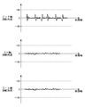
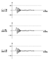
- FIG. 4, FIG. 5 and FIG. 6 show an example of the first rotation pattern.
- 3, 4, 5, and 6 show temporal changes in the respective rotation angles of the pitch axis, yaw axis, and roll axis as the first rotation pattern.
- the gimbal control unit 120 rotates the imaging device 200 based on the first rotation pattern, thereby reflecting the feeling that the user wants to express in the image through the rotation of the imaging device 200.
- FIG. 3 is an example of a first rotation pattern expressing that the user is nervous.
- FIG. 4 is an example of a first rotation pattern expressing that the user is impacted.
- FIG. 5 is an example of a first rotation pattern expressing that the user is experiencing an earthquake.
- FIG. 6 is an example of a first rotation pattern expressing that the user feels dizzy.
- the gimbal control unit 120 may rotate the imaging device 200 by controlling the support mechanism 110 based on a rotation pattern other than the first rotation pattern illustrated in FIGS. 3, 4, 5, and 6.
- the gimbal control unit 120 may give a desired effect to the image by using a function included in the imaging device 200 in addition to the rotation of the imaging device 200.
- the gimbal control unit 120 rotates at least one of the zoom operation and the focus operation of the imaging apparatus 200 so that a desired effect is given to an image captured by the imaging apparatus 200 while rotating the imaging apparatus 200 based on the first rotation pattern.
- the imaging apparatus 200 may be instructed to control the above.
- the imaging apparatus 200 moves some or all of the plurality of lenses 222 along the optical axis via the lens control unit 220, thereby at least performing zoom operation and focus operation. Run one.
- the gimbal control unit 120 rotates the imaging device 200 based on the first rotation pattern so that the imaging element 212 moves with respect to the optical axis so as to give a desired effect to an image captured by the imaging device 200.
- the imaging apparatus 200 may be instructed.
- the imaging apparatus 200 moves the imaging element 212 with respect to the optical axis via the imaging element moving mechanism 214.
- the plurality of first rotation patterns may be stored in the memory 122 of the gimbal 100.
- the gimbal control unit 120 may read the first rotation pattern designated by the user via the user interface 124 from the memory 122 and control the support mechanism 110 based on the read first rotation pattern.
- the gimbal control unit 120 may receive the first rotation pattern via the user interface 124.
- a plurality of first rotation patterns may be stored in another memory on the user interface 124 side.
- the mobile device 102 fixed to the stabilizer 10 may be used as the user interface 124.
- the mobile device 102 may store a plurality of first rotation patterns in a built-in memory.
- the mobile device 102 may read the first rotation pattern designated by the user from the built-in memory and transmit it to the gimbal control unit 120.
- the gimbal control unit 120 may control the support mechanism 110 based on the first rotation pattern received from the mobile device 102.
- the mobile device 102 may acquire the first rotation pattern via the network and provide the acquired first rotation pattern to the gimbal control unit 120.
- FIG. 7 shows an example of the temporal change of the zoom operation expressing that the user has encountered an earthquake.
- the gimbal control unit 120 may instruct the imaging apparatus 200 to execute the zoom operation with the operation pattern illustrated in FIG. 7 while controlling the support mechanism 110 based on the first rotation pattern illustrated in FIG. 5.
- FIG. 8 shows an example of a temporal change in the amount of movement of the image sensor 212 expressing that the user is experiencing an earthquake.
- the gimbal control unit 120 may instruct the imaging device 200 to move the imaging element 212 by the movement amount shown in FIG. 8 while controlling the support mechanism 110 based on the first rotation pattern shown in FIG.
- the imaging control unit 210 may move the imaging device 212 along the first direction perpendicular to the optical axis, for example, via the imaging device moving mechanism 214.
- the imaging control unit 210 may move the imaging device 212 along the first direction perpendicular to the optical axis, for example, via the imaging device moving mechanism 214.
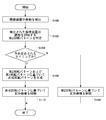
- FIG. 9 is a flowchart illustrating an example of a procedure in which the gimbal control unit 120 controls the support mechanism 110.
- the gimbal control unit 120 detects vibration of the imaging device 200 via the inertial measurement device 126 (S100).
- the gimbal control unit 120 specifies the second rotation pattern that suppresses the detected vibration of the imaging device 200 (S102).
- the gimbal control unit 120 determines whether or not it is a predetermined timing for executing control based on the first rotation pattern. For example, the gimbal control unit 120 may determine whether the time specified by the user via the user interface 124 has come. Or the gimbal control part 120 may determine whether the instruction
- the gimbal control unit 120 controls the support mechanism 110 based on the second rotation pattern (S106). For example, the gimbal control unit 120 controls the support mechanism 110 to rotate the imaging device 200 by ⁇ around the pitch axis in order to suppress vibration of the imaging device 200.
- the gimbal control unit 120 determines whether it is a predetermined timing. If it is a predetermined timing, the gimbal control unit 120 generates a combined rotation pattern based on the first rotation pattern and the second rotation pattern designated by the user via the user interface 124 (S108). The gimbal control unit 120 controls the support mechanism 110 based on the generated combined rotation pattern (S110). For example, the rotation about the pitch axis of the imaging device 200 based on the first rotation pattern is ⁇ (°), and the rotation about the pitch axis of the imaging device 200 based on the second rotation pattern is ⁇ (°). Suppose that In this case, the gimbal control unit 120 controls the support mechanism 110 so that the imaging apparatus 200 is rotated by ⁇ (°) about the pitch axis.
- the stabilizer 10 by rotating the imaging apparatus 200 using the gimbal 100, a desired effect can be given to the image through the rotation of the imaging apparatus 200.
- the gimbal control unit 120 may automatically select a first image pattern that gives an image an effect corresponding to the surrounding environment from among the plurality of first rotation patterns.
- the gimbal control unit 120 may acquire biological information of a specific living body, for example, a user, and may select a first rotation pattern from a plurality of first rotation patterns based on the acquired biological information.
- the gimbal control unit 120 may generate a first rotation pattern that gives a desired effect to an image captured by the imaging device 200 based on the biological information.
- the gimbal control unit 120 may rotate the imaging device 200 by controlling the support mechanism 110 based on the first rotation pattern selected or generated based on the biological information.
- FIG. 10 shows an example of functional blocks of the stabilizer 10 according to another embodiment.
- the stabilizer 10 shown in FIG. 10 is different from the stabilizer 10 shown in FIG. 2 in that the gimbal 100 has a biological sensor 128 and the gimbal control unit 120 includes an acquisition unit 121 and a generation unit 123.
- the biological sensor 128 detects the state of a specific living body.
- the biosensor 128 may detect, for example, at least one of a user's pulse, pulse wave, electrocardiogram waveform (such as a QRS waveform), brain wave, body temperature, and body motion.
- the memory 122 may store the first rotation pattern for each biological state specified by the biological information. For example, the memory 122 may store a first rotation pattern for each of a plurality of predetermined pulse rate ranges.
- the acquisition unit 121 acquires biological information indicating the state of the living body detected by the biological sensor 128.
- the gimbal control unit 120 may select the first rotation pattern from the plurality of first rotation patterns stored in the memory 122 based on the biological information acquired via the biological sensor 128.
- the generation unit 123 may generate a first rotation pattern that gives a desired effect to an image captured by the imaging device 200 based on the biological information acquired by the acquisition unit 121. For example, the generation unit 123 may determine the state of the user based on the biological information. The generation unit 123 may generate a first rotation pattern that gives an image an effect suitable for the user's state. The generation unit 123 may determine, based on the biological information, for example whether the user is in a resting state, a first excited state, or a second excited state in which the user is more excited than the first excited state. The generation unit 123 may generate the first rotation pattern according to the determined state.
- the generation unit 123 may generate a first rotation pattern in which the frequency increases in the order of the rest state, the first excitement state, and the second excitement state.
- the generation unit 123 may generate a first rotation pattern corresponding to a period indicated by a pulse wave or an electroencephalogram.
- FIG. 11 is a flowchart illustrating an example of a procedure in which the gimbal control unit 120 controls the support mechanism 110 based on the first rotation pattern based on the biological information.
- the gimbal control unit 120 detects the vibration of the imaging device 200 via the inertial measurement device 126 (S200). The gimbal control unit 120 specifies the second rotation pattern that suppresses the detected vibration of the imaging device 200 (S202). Next, the gimbal control unit 120 determines whether or not it is a predetermined timing for executing control based on the first rotation pattern (S204). If it is not a predetermined timing, the gimbal control unit 120 controls the support mechanism 110 based on the second rotation pattern (S206).
- the acquisition part 121 acquires a user's biometric information via the biometric sensor 128 (S208).
- the generation unit 123 generates a first rotation pattern based on the acquired biological information (S210).
- the gimbal control unit 120 generates a combined rotation pattern based on the second rotation pattern and the first rotation pattern (S212).
- the gimbal control unit 120 controls the support mechanism 110 based on the generated combined rotation pattern (S214).
- the gimbal control unit 120 may determine the user's state based on the biological information and generate a first rotation pattern suitable for the user's state. Thereby, by rotating the imaging device 200 by the gimbal 100 according to the user's state, a desired effect according to the user's state can be given to the image captured by the imaging device 200.
- FIG. 12 shows an example of a system including the UAV 300 and the remote controller 400 according to another embodiment.
- the UAV 300 includes a UAV main body 302, a gimbal 100, and an imaging device 200.
- the UAV 300 is an example of a moving body that includes the imaging device 200 and moves.
- the moving body is a concept including, in addition to UAV, other aircraft that moves in the air, vehicles that move on the ground, ships that move on the water, and the like.
- the UAV main body 302 includes a plurality of rotor blades.
- the UAV main body 302 causes the UAV 300 to fly by controlling the rotation of a plurality of rotor blades.
- the UAV main body 302 causes the UAV 300 to fly using four rotary wings.
- the number of rotor blades is not limited to four.
- the UAV 300 may be a fixed wing aircraft that does not have rotating blades.
- the remote controller 400 includes an operation unit 402 and a display unit 404.
- the operation unit 402 receives an input operation for controlling the posture of the UAV 300 from the user.
- the remote controller 400 transmits a signal for controlling the UAV 300 based on a user operation received by the operation unit 402.
- the remote controller 400 receives an image captured by the imaging device 200.
- the display unit 404 displays an image received by the remote controller 400.
- the display unit 404 may be a touch panel.
- the remote controller 400 may accept an input operation from the user through the display unit 404. At least one of the operation unit 402 and the display unit 404 may function as a user interface.
- FIG. 13 shows an example of functional blocks of the UAV 300 and the remote controller 400.
- the UAV 300 includes a UAV main body 302, a gimbal 100, and an imaging device 200.
- the remote controller 400 includes a remote control unit 410, a biological sensor 420, a communication interface 422, a user interface 424, and a memory 426.
- the remote controller 400 includes the user interface 424 and the biosensor 420.
- the UAV main body 302 includes a UAV control unit 310, a propulsion unit 320, a memory 322, and a communication interface 324.
- the communication interface 324 communicates with the remote controller 400.
- the communication interface 324 receives various commands for the UAV control unit 310 from the remote controller 400.
- the memory 322 stores programs necessary for the UAV control unit 310 to control the propulsion unit 320, the gimbal 100, and the imaging device 200.
- the memory 322 may be a computer-readable recording medium and may include at least one of flash memory such as SRAM, DRAM, EPROM, EEPROM, and USB memory.
- the memory 322 may be provided inside the UAV main body 302. It may be provided so as to be removable from the UAV main body 302.
- the UAV control unit 310 controls the flight and imaging of the UAV 300 in accordance with a program stored in the memory 322.
- the UAV control unit 310 may be configured by a microprocessor such as a CPU or MPU, a microcontroller such as an MCU, or the like.
- the UAV control unit 310 controls flight and imaging of the UAV 300 according to a command received from the remote controller 400 via the communication interface 324.
- the propulsion unit 320 propels the UAV 300.
- the propulsion unit 320 includes a plurality of rotor blades and a plurality of drive motors that rotate the rotor blades.
- the propulsion unit 320 causes the UAV 300 to fly by rotating a plurality of rotor blades via a plurality of drive motors in accordance with a command from the UAV control unit 310.
- the plurality of first rotation patterns may be stored in the memory 122.
- the gimbal control unit 120 receives a control signal indicating the first rotation pattern designated by the user via the user interface 424 via the UAV main body 302.
- the gimbal control unit 120 may read the first rotation pattern indicated by the control signal from the memory 122 and control the support mechanism 110 based on the read first rotation pattern.
- the plurality of first rotation patterns may be stored in the memory 426.
- the user designates a first rotation pattern from among a plurality of first rotation patterns stored in the memory 426 via the user interface 424.
- the remote control unit 410 reads the designated first rotation pattern from the memory 426 and transmits it to the UAV 300.
- the gimbal control unit 120 receives the first rotation pattern from the UAV main body 302.
- the gimbal control unit 120 may control the support mechanism 110 based on the first rotation pattern received from the remote controller 400 via the UAV main body 302.
- the living body sensor 420 detects the state of a specific living body.
- the biological sensor 420 may detect, for example, at least one of a pulse, a pulse wave, an electrocardiogram waveform (such as a QRS waveform), an electroencephalogram, a body temperature, and a body motion of the user who operates the remote controller 400.
- the remote controller 400 transmits biological information indicating the state of the biological body detected by the biological sensor 420 to the gimbal 100 via the UAV main body 302.
- the acquisition unit 121 acquires biological information from the remote controller 400.
- the generation unit 123 may generate a first rotation pattern that gives a desired effect to an image captured by the imaging device 200 based on the biological information acquired by the acquisition unit 121.
- the gimbal control unit 120 may control the support mechanism 110 based on the first rotation pattern generated by the generation unit 123.
- the biosensor 420 may be removable from the remote controller 400.
- the imaging device 200 is intentionally rotated using the gimbal 100, and an image having various effects can be captured by the imaging device 200 mounted on the UAV 300. .
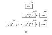
- FIG. 14 illustrates an example of a computer 1200 in which aspects of the present invention may be embodied in whole or in part.
- a program installed in the computer 1200 can cause the computer 1200 to function as an operation associated with the apparatus according to the embodiment of the present invention or as one or more “units” of the apparatus.
- the program can cause the computer 1200 to execute the operation or the one or more “units”.
- the program can cause the computer 1200 to execute a process according to an embodiment of the present invention or a stage of the process.
- Such a program may be executed by CPU 1212 to cause computer 1200 to perform certain operations associated with some or all of the blocks in the flowcharts and block diagrams described herein.
- the computer 1200 includes a CPU 1212 and a RAM 1214, which are connected to each other by a host controller 1210.
- the computer 1200 also includes a communication interface 1222 and an input / output unit, which are connected to the host controller 1210 via the input / output controller 1220.
- Computer 1200 also includes ROM 1230.
- the CPU 1212 operates according to programs stored in the ROM 1230 and the RAM 1214, thereby controlling each unit.
- the communication interface 1222 communicates with other electronic devices via a network.
- a hard disk drive may store programs and data used by CPU 1212 in computer 1200.
- the ROM 1230 stores therein a boot program executed by the computer 1200 at the time of activation and / or a program depending on the hardware of the computer 1200.
- the program is provided via a computer-readable recording medium such as a CR-ROM, a USB memory, or an IC card or a network.
- the program is installed in the RAM 1214 or the ROM 1230 that is also an example of a computer-readable recording medium, and is executed by the CPU 1212.
- Information processing described in these programs is read by the computer 1200 to bring about cooperation between the programs and the various types of hardware resources.
- An apparatus or method may be configured by implementing information manipulation or processing in accordance with the use of computer 1200.
- the CPU 1212 executes a communication program loaded in the RAM 1214 and performs communication processing on the communication interface 1222 based on the processing described in the communication program. You may order.
- the communication interface 1222 reads transmission data stored in a transmission buffer processing area provided in a recording medium such as a RAM 1214 or a USB memory under the control of the CPU 1212, and transmits the read transmission data to the network, or The reception data received from the network is written into a reception buffer processing area provided on the recording medium.
- the CPU 1212 allows the RAM 1214 to read all or necessary portions of a file or database stored in an external recording medium such as a USB memory, and executes various types of processing on the data on the RAM 1214. Good. Next, the CPU 1212 writes back the processed data to the external recording medium.
- the CPU 1212 describes various types of operations, information processing, conditional judgment, conditional branching, unconditional branching, and information retrieval that are described in various places in the present disclosure for data read from the RAM 1214 and specified by the instruction sequence of the program. Various types of processing may be performed, including / replacement, etc., and the result is written back to RAM 1214.
- the CPU 1212 may search for information in files, databases, etc. in the recording medium. For example, when a plurality of entries each having an attribute value of the first attribute associated with the attribute value of the second attribute are stored in the recording medium, the CPU 1212 specifies the attribute value of the first attribute. The entry that matches the condition is searched from the plurality of entries, the attribute value of the second attribute stored in the entry is read, and thereby the first attribute that satisfies the predetermined condition is associated. The attribute value of the obtained second attribute may be acquired.
- the programs or software modules described above may be stored on a computer-readable medium on the computer 1200 or in the vicinity of the computer 1200.
- a recording medium such as a hard disk or a RAM provided in a server system connected to a dedicated communication network or the Internet can be used as a computer-readable medium, thereby providing a program to the computer 1200 via the network. To do.
Landscapes
- Engineering & Computer Science (AREA)
- General Engineering & Computer Science (AREA)
- Physics & Mathematics (AREA)
- General Physics & Mathematics (AREA)
- Multimedia (AREA)
- Signal Processing (AREA)
- Mechanical Engineering (AREA)
- Studio Devices (AREA)
- Accessories Of Cameras (AREA)
- Adjustment Of Camera Lenses (AREA)
Abstract
支持機構に回転可能に支持された撮像装置において、撮像装置により撮像される画像に対して、支持機構を利用して所望の効果を与えられない場合がある。制御装置は、少なくとも一軸を中心に撮像装置を回転可能に支持する支持機構を、撮像装置により撮像される画像に所望の効果を与える第1回転パターンに基づいて、制御することにより、撮像装置を回転させる制御部を備える。
Description
本発明は、制御装置、撮像システム、移動体、制御方法、およびプログラムに関する。
特許文献1には、撮像装置からの映像信号の切り替えまたは映像信号にエフェクトを施す映像加工処理に連動させて撮像装置の動作を制御することが記載されている。
特許文献1 特開2011-176415号公報
特許文献1 特開2011-176415号公報
支持機構に回転可能に支持された撮像装置において、撮像装置により撮像される画像に対して、支持機構を利用して所望の効果を与えられない場合がある。
本発明の一態様に係る制御装置は、少なくとも一軸を中心に撮像装置を回転可能に支持する支持機構を、撮像装置により撮像される画像に所望の効果を与える第1回転パターンに基づいて、制御することにより、撮像装置を回転させる制御部を備える。
制御装置は、撮像装置の振動を検出する検出部を備えてよい。制御部は、検出部により検出された撮像装置の振動を抑制する第2回転パターンを特定してよい。制御部は、第1回転パターンおよび第2回転パターンに基づく第3回転パターンに基づいて支持機構を制御することにより、撮像装置を回転させてよい。
制御部は、撮像装置により撮像される画像に異なる所望の効果を与える複数の第1回転パターンの中から第1回転パターンの指定を受け付けてよい。制御部は、指定された第1回転パターンに基づいて、支持機構を制御することにより撮像装置を回転させてよい。
制御部は、撮像装置を回転させるタイミングの指定を受け付けてよい。制御部は、指定されたタイミングで、支持機構を制御することにより撮像装置を回転させてよい。
制御部は、第1回転パターンに基づいて支持機構を制御することにより撮像装置を回転させながら、撮像装置により撮像される画像に所望の効果が与えられるように、撮像装置のズーム動作およびフォーカス動作の少なくとも一方を制御するように撮像装置に指示してよい。
制御部は、第1回転パターンに基づいて撮像装置を回転させながら、撮像装置により撮像される画像に所望の効果が与えられるように、撮像装置が有する撮像素子と撮像素子に光を入射させるレンズとを光軸と異なる方向に相対的に移動させるように撮像装置に指示する。
制御部は、生体の生体情報を取得してよい。制御部は、撮像装置により撮像される画像に異なる所望の効果を与える複数の第1回転パターンの中から生体情報に基づいて第1回転パターンを選択してよい。
第1回転パターンは、緊張、衝撃、地震、および眩暈の少なくとも1つを表現する効果を画像に与えてよい。
本発明の一態様に係る制御装置は、少なくとも一軸を中心に撮像装置を回転可能に支持する支持機構を制御することで、撮像装置を回転させる制御部を備えてよい。制御部は、生体の生体情報を取得してよい。制御部は、生体情報に基づいて、撮像装置により撮像される画像に所望の効果を与える第1回転パターンを生成してよい。制御部は、生成された第1回転パターンに基づいて支持機構を制御することにより、撮像装置を回転させてよい。
制御装置は、撮像装置の振動を検出する検出部を備えてよい。制御部は、検出部により検出された撮像装置の振動を抑制する第2回転パターンを特定してよい。制御部は、生成された第1回転パターンおよび第2回転パターンに基づく第3回転パターンで支持機構を制御することにより、撮像装置を回転させてよい。
本発明の一態様に係る撮像システムは、上記制御装置と、撮像装置と、支持機構とを備えてよい。撮像システムは、支持機構に取り付けられる持ち手部を備えてよい。
本発明の一態様に係る移動体は、上記撮像システムを備えて移動してよい。
本発明の一態様に係る制御方法は、少なくとも一軸を中心に撮像装置を回転可能に支持する支持機構を、撮像装置により撮像される画像に所望の効果を与える第1回転パターンに基づいて、制御することにより、撮像装置を回転させる段階を備えてよい。
本発明の一態様に係るプログラムは、少なくとも一軸を中心に撮像装置を回転可能に支持する支持機構を、撮像装置により撮像される画像に所望の効果を与える第1回転パターンに基づいて、制御することにより、撮像装置を回転させる段階をコンピュータに実行させてよい。
本発明の一態様に係る制御方法は、生体の生体情報を取得する段階を備えてよい。制御方法は、生体情報に基づいて、撮像装置により撮像される画像に所望の効果を与える第1回転パターンを生成する段階を備えてよい。制御方法は、少なくとも一軸を中心に撮像装置を回転可能に支持する支持機構を第1回転パターンに基づいて制御することで、撮像装置を回転させる段階を備えてよい。
本発明の一態様に係るプログラムは、生体の生体情報を取得する段階をコンピュータに実行させてよい。プログラムは、生体情報に基づいて、撮像装置により撮像される画像に所望の効果を与える第1回転パターンを生成する段階をコンピュータに実行させてよい。プログラムは、少なくとも一軸を中心に撮像装置を回転可能に支持する支持機構を第1回転パターンに基づいて制御することで、撮像装置を回転させる段階をコンピュータに実行させてよい。
支持機構に回転可能に支持された撮像装置において、撮像装置により撮像される画像に対して、支持機構を利用して所望の効果を与えることができる。
上記の発明の概要は、本発明の特徴の全てを列挙したものではない。これらの特徴群のサブコンビネーションも発明となりうる。
以下、発明の実施の形態を通じて本発明を説明するが、以下の実施形態は請求の範囲にかかる発明を限定するものではない。また、実施形態の中で説明されている特徴の組み合わせの全てが発明の解決手段に必須であるとは限らない。
請求の範囲、明細書、図面、および要約書には、著作権による保護の対象となる事項が含まれる。著作権者は、これらの書類の何人による複製に対しても、特許庁のファイルまたはレコードに表示される通りであれば異議を唱えない。ただし、それ以外の場合、一切の著作権を保留する。
本発明の様々な実施形態は、フローチャートおよびブロック図を参照して記載されてよく、ここにおいてブロックは、(1)操作が実行されるプロセスの段階または(2)操作を実行する役割を持つ装置の「部」を表わしてよい。特定の段階および「部」が、プログラマブル回路、および/またはプロセッサによって実装されてよい。専用回路は、デジタルおよび/またはアナログハードウェア回路を含んでよい。集積回路(IC)および/またはディスクリート回路を含んでよい。プログラマブル回路は、再構成可能なハードウェア回路を含んでよい。再構成可能なハードウェア回路は、論理AND、論理OR、論理XOR、論理NAND、論理NOR、および他の論理操作、フリップフロップ、レジスタ、フィールドプログラマブルゲートアレイ(FPGA)、プログラマブルロジックアレイ(PLA)等のようなメモリ要素等を含んでよい。
コンピュータ可読媒体は、適切なデバイスによって実行される命令を格納可能な任意の有形なデバイスを含んでよい。その結果、そこに格納される命令を有するコンピュータ可読媒体は、フローチャートまたはブロック図で指定された操作を実行するための手段を作成すべく実行され得る命令を含む、製品を備えることになる。コンピュータ可読媒体の例としては、電子記憶媒体、磁気記憶媒体、光記憶媒体、電磁記憶媒体、半導体記憶媒体等が含まれてよい。コンピュータ可読媒体のより具体的な例としては、フロッピー(登録商標)ディスク、ディスケット、ハードディスク、ランダムアクセスメモリ(RAM)、リードオンリメモリ(ROM)、消去可能プログラマブルリードオンリメモリ(EPROMまたはフラッシュメモリ)、電気的消去可能プログラマブルリードオンリメモリ(EEPROM)、静的ランダムアクセスメモリ(SRAM)、コンパクトディスクリードオンリメモリ(CD-ROM)、デジタル多用途ディスク(DVD)、ブルーレイ(RTM)ディスク、メモリスティック、集積回路カード等が含まれてよい。
コンピュータ可読命令は、1または複数のプログラミング言語の任意の組み合わせで記述されたソースコードまたはオブジェクトコードの何れかを含んでよい。ソースコードまたはオブジェクトコードは、従来の手続型プログラミング言語を含む。従来の手続型プログラミング言語は、アセンブラ命令、命令セットアーキテクチャ(ISA)命令、マシン命令、マシン依存命令、マイクロコード、ファームウェア命令、状態設定データ、またはSmalltalk、JAVA(登録商標)、C++等のようなオブジェクト指向プログラミング言語、および「C」プログラミング言語または同様のプログラミング言語でよい。コンピュータ可読命令は、汎用コンピュータ、特殊目的のコンピュータ、若しくは他のプログラム可能なデータ処理装置のプロセッサまたはプログラマブル回路に対し、ローカルにまたはローカルエリアネットワーク(LAN)、インターネット等のようなワイドエリアネットワーク(WAN)を介して提供されてよい。プロセッサまたはプログラマブル回路は、フローチャートまたはブロック図で指定された操作を実行するための手段を作成すべく、コンピュータ可読命令を実行してよい。プロセッサの例としては、コンピュータプロセッサ、処理ユニット、マイクロプロセッサ、デジタル信号プロセッサ、コントローラ、マイクロコントローラ等を含む。
図1は、実施形態に係るスタビライザ10の一例を示す外観斜視図である。スタビライザ10は、ジンバル100、撮像装置200、および持ち手部103を備える。スタビライザ10は、制御装置および撮像システムの一例である。ジンバル100は、撮像装置200を回転可能に支持する。ジンバル100は、ヨー軸回転機構112、ピッチ軸回転機構114、およびロール軸回転機構116を有する。ジンバル100は、ヨー軸(パン軸)、ピッチ軸(チルト軸)、およびロール軸を中心に、撮像装置200を回転可能に支持する。
撮像装置200は、メモリを挿入するためのスロット202を有する。ジンバル100は、ホルダ107を介して持ち手部103に固定される。持ち手部103は、ジンバル100および撮像装置200を操作するための各種ボタンを有する。持ち手部103は、ユーザインタフェースとして、シャッターボタン104、録画ボタン105、および操作ボタン106を含む。シャッターボタン104が押下されることで、撮像装置200により静止画を記録することができる。録画ボタン105が押下されることで、撮像装置200により動画を記録することができる。
デバイスホルダ101が持ち手部103に固定されている。デバイスホルダ101は、スマートフォンなどのモバイルデバイス102を保持する。モバイルデバイス102は、WiFiなどの無線ネットワークを介してスタビライザ10と通信可能に接続される。これにより、撮像装置200により撮像された画像をモバイルデバイス102の画面に表示させることができる。モバイルデバイス102がジンバル100および撮像装置200の少なくとも一方を操作するユーザインタフェースとして機能してもよい。
スタビライザ10は、スタビライザ10を保持するユーザによる手振れを打ち消すように、ジンバル100により撮像装置200を回転させる。ジンバル100は、例えば、ヨー軸およびピッチ軸の少なくとも一方を中心に撮像装置200を回転させて、手振れを打ち消してよい。
このように構成されたスタビライザ10において、撮像装置200により撮像される画像に、ジンバル100を用いてより多彩な効果を与える。
図2は、実施形態に係るスタビライザ10の機能ブロックの一例を示す。スタビライザ10は、ジンバル100および撮像装置200を備える。ジンバル100は、支持機構110、ジンバル制御部120、メモリ122、ユーザインタフェース124、および慣性計測装置126を備える。支持機構110は、ヨー軸回転機構112、ピッチ軸回転機構114、およびロール軸回転機構116を有する。ヨー軸回転機構112は、ヨー軸を中心に撮像装置200を回転させる。ピッチ軸回転機構114は、ピッチ軸を中心に撮像装置200を回転させる。ロール軸回転機構116は、ロール軸を中心に撮像装置200を回転させる。
ジンバル制御部120は、支持機構110による撮像装置200の回転を制御する。ジンバル制御部120は、制御部の一例である。ジンバル制御部120は、CPUまたはMPUなどのマイクロプロセッサ、MCUなどのマイクロコントローラなどにより構成されてよい。メモリ122は、ジンバル制御部120が支持機構110を制御するのに必要なプログラムなどを格納する。メモリ122は、コンピュータ可読可能な記録媒体でよく、SRAM、DRAM、EPROM、EEPROM、およびUSBメモリなどのフラッシュメモリの少なくとも1つを含んでよい。メモリ122は、スタビライザ10の筐体に設けられてよい。スタビライザ10の筐体から取り外し可能に設けられてよい。ジンバル制御部120は、スタビライザ10を撮像システムとして機能させてよい。
ユーザインタフェース124は、ユーザからの指示を受け付ける。ユーザインタフェース124は、例えば、シャッターボタン104、録画ボタン105、および操作ボタン106を含む。慣性計測装置(IMU)126は、撮像装置200の振動を検出する。慣性計測装置126は、ヨー軸、ピッチ軸、およびロール軸における撮像装置200の角速度および加速度を撮像装置200の振動を示す指標として検出する。慣性計測装置126は、撮像装置200の振動を検出する検出部の一例である。慣性計測装置126は、撮像装置200に設けられてもよい。慣性計測装置126は、ジンバル100および撮像装置200の少なくとも一方に設けられてよい。
撮像装置200は、撮像制御部210、撮像素子212、撮像素子移動機構214、レンズ制御部220、複数のレンズ222、レンズ移動機構224、およびメモリ230を備える。撮像制御部210は、CPUまたはMPUなどのマイクロプロセッサ、MCUなどのマイクロコントローラなどにより構成されてよい。撮像制御部210は、ジンバル制御部120からの撮像装置200の動作命令に応じて、撮像装置200を制御する。メモリ230は、コンピュータ可読可能な記録媒体でよく、SRAM、DRAM、EPROM、EEPROM、およびUSBメモリなどのフラッシュメモリの少なくとも1つを含んでよい。メモリ230は、撮像装置200の筐体の内部に設けられてよい。メモリ230は、撮像装置200の筐体から取り外し可能に設けられてよい。
撮像素子212は、CCDまたはCMOSにより構成されてよい。撮像素子212は、撮像装置200の筐体の内部に保持され、複数のレンズ222を介して結像された光学像の画像データを生成して、撮像制御部210に出力する。撮像制御部210は、撮像素子212から出力された画像データをメモリ230に格納する。撮像制御部210は、画像データをジンバル制御部120を介してメモリ122に出力して格納してもよい。
レンズ制御部220は、レンズ移動機構224を介して複数のレンズ222の移動を制御する。複数のレンズ222の一部または全部は、レンズ移動機構224により光軸に沿って移動する。レンズ制御部220は、撮像制御部210からのレンズ動作命令に従って、複数のレンズ222の少なくとも一つを光軸に沿って移動させる。レンズ制御部220は、複数のレンズ222の少なくとも一つを光軸に沿って移動させることで、ズーム動作およびフォーカス動作の少なくとも一方を実行する。
撮像素子移動機構214は、手振れを打ち消すように撮像素子212を光軸と異なる方向に移動させる。撮像素子移動機構214は、手振れを打ち消すように撮像素子212を光軸と異なる方向に複数のレンズ222に対して相対的に移動させてよい。撮像素子移動機構214は、撮像素子212を光軸に垂直な第1方向に移動させてよい。撮像素子移動機構214は、撮像素子212を光軸に垂直な第1方向とは異なる第2方向に移動させてよい。撮像素子移動機構214は、撮像素子212を光軸を中心に回転させてよい。撮像装置200は、撮像素子移動機構214を利用して撮像素子212を光軸に対して移動させることで、手振れ補正機能を実現する。撮像装置200は、撮像素子212の代わりに、複数のレンズ222を光軸と異なる方向に移動させてよい。撮像装置200は、複数のレンズ222のいずれかを光軸と異なる方向に移動させることで光の屈折方向を変更してよい。これにより、撮像装置200は、撮像素子212を光軸と異なる方向に複数のレンズ222に対して相対的に移動させてよい。手振れとは、例えばスタビライザ10に加わる外的な力による揺れ、またはスタビライザ10内で発生する機械的な揺れである。
このように構成されたスタビライザ10において、ジンバル制御部120は、撮像装置200により撮像される画像に所望の効果を与える第1回転パターンに基づいて、支持機構110を制御することにより、撮像装置200を回転させる。所望の効果は、撮像装置200が撮像するときに撮像装置200を意図的に回転させることで画像に与えられる効果でよい。所望の効果は、撮像装置200が動画を撮影しているときに撮像装置200を意図的に回転させることで動画に与えられる効果でよい。所望の効果が与えられた動画は、揺れている映像を含んでよい。所望の効果が与えられた動画は、小刻みに揺れている映像を含んでよい。所望の効果が与えられた動画は、周期的に揺れている映像を含んでよい。所望の効果が与えられた動画は、回転する映像を含んでよい。
ジンバル制御部120は、予め定められた第1回転パターンに基づいて、支持機構110を制御することにより、撮像装置200を回転させてよい。ジンバル制御部120は、第1回転パターンに基づいて支持機構110を制御することにより、撮像装置200を第1方向および第1方向と反対の第2方向に交互に周期的に回転させてよい。ジンバル制御部120は、慣性計測装置126により検出された撮像装置200の振動を抑制する第2回転パターンを特定してよい。ジンバル制御部120は、第1回転パターンおよび第2回転パターンに基づく第3回転パターンに基づいて支持機構110を制御することにより、撮像装置200を回転させてよい。ジンバル制御部120は、第1回転パターンおよび第2回転パターンを合成した合成回転パターンを第3回転パターンとして用いてよい。
ジンバル制御部120は、撮像装置200により撮像される画像に異なる所望の効果を与える複数の第1回転パターンの中から第1回転パターンの指定を受け付けてよい。ジンバル制御部120は、ユーザインタフェース124を介してユーザから第1回転パターンの指定を受け付けてよい。ジンバル制御部120は、指定された第1回転パターンに基づいて、支持機構110を制御することにより撮像装置200を回転させてよい。ユーザインタフェース124が、ユーザからの指示に応じて、複数の第1回転パターンの中から第1回転パターンを指定してよい。
ジンバル制御部120は、撮像装置200を回転させるタイミングをさらに受け付けてよい。ジンバル制御部120は、ユーザインタフェース124を介して撮像装置200を回転させるタイミングを受け付けてよい。ユーザインタフェース124は、ユーザからの指示に応じて、撮像装置200を回転させるタイミングを指定してよい。ジンバル制御部120は、ユーザインタフェース124により指定されたタイミングで、支持機構110を制御することにより撮像装置200を回転させてよい。
図3、図4、図5、および図6は、第1回転パターンの一例を示す。図3、図4、図5、および図6は、第1回転パターンとして、ピッチ軸、ヨー軸、およびロール軸のそれぞれの回転角度の時間的変化を示す。ジンバル制御部120は、第1回転パターンに基づいて撮像装置200を回転させることで、ユーザが表現したい感覚を撮像装置200の回転を通じて画像に反映する。
図3は、ユーザが緊張していることを表現する第1回転パターンの一例である。図4は、ユーザが衝撃を受けていることを表現する第1回転パターンの一例である。図5は、ユーザが地震に遭遇していることを表現する第1回転パターンの一例である。図6は、ユーザが眩暈を感じていることを表現する第1回転パターンの一例である。ジンバル制御部120は、図3、図4、図5、および図6に示す第1回転パターン以外の回転パターンに基づいて、支持機構110を制御することにより、撮像装置200を回転させてよい。
ジンバル制御部120は、撮像装置200の回転に加えて、撮像装置200が備える機能を利用して、画像に所望の効果を与えてよい。ジンバル制御部120は、第1回転パターンに基づいて撮像装置200を回転させながら、撮像装置200により撮像される画像に所望の効果が与えられるべく、撮像装置200のズーム動作およびフォーカス動作の少なくとも一方を制御するように撮像装置200に指示してよい。撮像装置200は、ジンバル制御部120からの指示を受けて、レンズ制御部220を介して複数のレンズ222の一部または全部を光軸に沿って移動させることで、ズーム動作およびフォーカス動作の少なくとも一方を実行する。
ジンバル制御部120は、第1回転パターンに基づいて撮像装置200を回転させながら、撮像装置200により撮像される画像に所望の効果が与えるべく、撮像素子212が光軸に対して移動するように撮像装置200に指示してよい。撮像装置200は、ジンバル制御部120からの指示を受けて、撮像素子移動機構214を介して撮像素子212を光軸に対して移動させる。
複数の第1回転パターンは、ジンバル100のメモリ122に格納されてよい。この場合、ジンバル制御部120は、ユーザインタフェース124を介してユーザにより指定された第1回転パターンをメモリ122から読み出して、読み出した第1回転パターンに基づいて支持機構110を制御してよい。
ジンバル制御部120は、ユーザインタフェース124を介して第1回転パターンを受信してもよい。この場合、ユーザインタフェース124側の他のメモリに複数の第1回転パターンが記憶されていてよい。例えば、ユーザインタフェース124として、スタビライザ10に固定されたモバイルデバイス102を利用してよい。モバイルデバイス102は、内蔵のメモリに複数の第1回転パターンを記憶してよい。モバイルデバイス102は、ユーザから指定された第1回転パターンを内蔵メモリから読み出して、ジンバル制御部120に送信してよい。ジンバル制御部120は、モバイルデバイス102から受信した第1回転パターンに基づいて支持機構110を制御してよい。モバイルデバイス102は、ネットワークを介して第1回転パターンを取得して、取得した第1回転パターンをジンバル制御部120に提供してよい。
図7は、ユーザが地震に遭遇していることを表現するズーム動作の時間的変化の一例を示す。ジンバル制御部120は、図5に示す第1回転パターンに基づいて支持機構110を制御しながら、図7に示す動作パターンでズーム動作を実行させるべく、撮像装置200に指示してよい。図8は、ユーザが地震に遭遇していることを表現する撮像素子212の移動量の時間的変化の一例を示す。ジンバル制御部120は、図5に示す第1回転パターンに基づいて支持機構110を制御しながら、図8に示す移動量で撮像素子212を移動させるべく、撮像装置200に指示してよい。撮像制御部210は、ジンバル制御部120からの指示を受けて、撮像素子移動機構214を介して、例えば光軸に垂直な第1方向に沿って撮像素子212を移動させてよい。このように、撮像装置200の回転に加えて、撮像装置200の既存の機能を活用することで、より多彩な効果を画像に与えることができる。
図9は、ジンバル制御部120が支持機構110を制御する手順の一例を示すフローチャートである。ジンバル制御部120は、慣性計測装置126を介して撮像装置200の振動を検出する(S100)。ジンバル制御部120は、検出された撮像装置200の振動を抑制する第2回転パターンを特定する(S102)。次いで、ジンバル制御部120は、第1回転パターンに基づく制御を実行する予め定められたタイミングか否かを判定する。ジンバル制御部120は、例えば、ユーザインタフェース124を介してユーザにより指定された時間になったかどうかを判定してよい。または、ジンバル制御部120は、例えば、ユーザインタフェース124を介してユーザにより第1回転パターンに基づく制御を実行する指示を受けたか否かを判定してよい。
予め定められたタイミングでなければ、ジンバル制御部120は、第2回転パターンに基づいて支持機構110を制御する(S106)。ジンバル制御部120は、例えば、撮像装置200の振動を抑制するために撮像装置200をピッチ軸を中心に-αだけ回転させるように支持機構110を制御する。
一方、予め定められたタイミングであれば、ジンバル制御部120は、ユーザインタフェース124を介してユーザにより指定された第1回転パターンおよび第2回転パターンに基づいて合成回転パターンを生成する(S108)。ジンバル制御部120は、生成された合成回転パターンに基づいて支持機構110を制御する(S110)。例えば、第1回転パターンに基づく撮像装置200のピッチ軸を中心とした回転がθ(°)であり、第2回転パターンに基づく撮像装置200のピッチ軸を中心とした回転が-α(°)であるとする。この場合、ジンバル制御部120は、撮像装置200をピッチ軸を中心にθ-α(°)だけ回転させるように支持機構110を制御する。
以上の通り、本実施形態に係るスタビライザ10によれば、ジンバル100を利用して撮像装置200を回転させることで、撮像装置200の回転を通じて所望の効果を画像に与えることができる。
上記の例では、ユーザインタフェース124を介してユーザが複数の第1回転パターンの中から所望の効果を画像に与えられる第1回転パターンを指定する例について説明した。しかし、ジンバル制御部120は、複数の第1回転パターンの中から周囲の環境に応じた効果を画像に与えられる第1画像パターンを自動的に選択してもよい。ジンバル制御部120は、特定の生体、例えばユーザの生体情報を取得し、取得された生体情報に基づいて複数の第1回転パターンの中から第1回転パターンを選択してよい。ジンバル制御部120は、生体情報に基づいて、撮像装置200により撮像される画像に所望の効果を与える第1回転パターンを生成してよい。ジンバル制御部120は、生体情報に基づいて選択または生成された第1回転パターンに基づいて支持機構110を制御することにより、撮像装置200を回転させてよい。
図10は、他の実施形態に係るスタビライザ10の機能ブロックの一例を示す。図10に示すスタビライザ10は、ジンバル100が生体センサ128を有する点、およびジンバル制御部120が取得部121および生成部123を含む点で、図2に示すスタビライザ10と異なる。
生体センサ128は、特定の生体の状態を検出する。生体センサ128は、例えば、ユーザの脈拍、脈波、心電図の波形(QRS波形など)、脳波、体温、および体動の少なくとも1つを検出してよい。メモリ122は、生体情報により特定される生体の状態ごとに、第1回転パターンを記憶してよい。メモリ122は、例えば、予め定められた複数の脈拍数範囲ごとに第1回転パターンを記憶してよい。取得部121は、生体センサ128により検出された生体の状態を示す生体情報を取得する。ジンバル制御部120は生体センサ128を介して取得された生体情報に基づいて、メモリ122に記憶された複数の第1回転パターンの中から第1回転パターンを選択してよい。
生成部123は、取得部121により取得された生体情報に基づいて、撮像装置200により撮像される画像に所望の効果を与える第1回転パターンを生成してよい。生成部123は、例えば、生体情報に基づいてユーザの状態を判別してよい。生成部123は、ユーザの状態に適した効果を画像に与える第1回転パターンを生成してよい。生成部123は、生体情報に基づいて、例えばユーザが安静状態、第1興奮状態、第1興奮状態より興奮している第2興奮状態のいずれかの状態にあるかを判別してよい。生成部123は、判別された状態に応じて、第1回転パターンを生成してよい。生成部123は、安静状態、第1興奮状態、第2興奮状態の順に、周波数が高くなる第1回転パターンを生成してよい。生成部123は、脈波または脳波などが示す周期に対応する第1回転パターンを生成してよい。
図11は、ジンバル制御部120が生体情報に基づく第1回転パターンに基づき支持機構110を制御する手順の一例を示すフローチャートである。
ジンバル制御部120は、慣性計測装置126を介して撮像装置200の振動を検出する(S200)。ジンバル制御部120は、検出された撮像装置200の振動を抑制する第2回転パターンを特定する(S202)。次いで、ジンバル制御部120は、第1回転パターンに基づく制御を実行する予め定められたタイミングか否かを判定する(S204)。予め定められたタイミングでなければ、ジンバル制御部120は、第2回転パターンに基づいて支持機構110を制御する(S206)。
一方、予め定められたタイミングであれば、取得部121が生体センサ128を介してユーザの生体情報を取得する(S208)。生成部123は、取得された生体情報に基づいて第1回転パターンを生成する(S210)。次いで、ジンバル制御部120は、第2回転パターンおよび第1回転パターンに基づいて合成回転パターンを生成する(S212)。ジンバル制御部120は、生成された合成回転パターンに基づいて支持機構110を制御する(S214)。
以上の通り、ジンバル制御部120は、生体情報に基づいてユーザの状態を判別して、ユーザの状態に適した第1回転パターンを生成してよい。これにより、ユーザの状態に応じてジンバル100により撮像装置200を回転させることで、撮像装置200により撮像される画像にユーザの状態に応じた所望の効果を与えることができる。
上記の実施形態では、スタビライザ10に設けられるジンバル100を利用する例について説明した。しかし、無人航空機(UAV)などの移動体に搭載されるジンバル100を利用して撮像装置200を回転させることで、撮像装置200により撮像される画像に所望の効果を与えてもよい。
図12は、他の実施形態に係るUAV300およびリモートコントローラ400を含むシステムの一例を示す。UAV300は、UAV本体302、ジンバル100、および撮像装置200を備える。UAV300は、撮像装置200を備えて移動する移動体の一例である。移動体とは、UAVの他、空中を移動する他の航空機、地上を移動する車両、水上を移動する船舶等を含む概念である。
UAV本体302は、複数の回転翼を備える。UAV本体302は、複数の回転翼の回転を制御することでUAV300を飛行させる。UAV本体302は、例えば、4つの回転翼を用いてUAV300を飛行させる。回転翼の数は、4つには限定されない。UAV300は、回転翼を有さない固定翼機でもよい。
リモートコントローラ400は、操作部402および表示部404を備える。操作部402は、UAV300の姿勢を制御するための入力操作をユーザから受け付ける。リモートコントローラ400は、操作部402が受け付けたユーザの操作に基づいて、UAV300を制御するための信号を送信する。
リモートコントローラ400は、撮像装置200により撮像された画像を受信する。表示部404は、リモートコントローラ400が受信した画像を表示する。表示部404はタッチ式のパネルであってよい。リモートコントローラ400は、表示部404を通じて、ユーザから入力操作を受け付けてよい。操作部402および表示部404の少なくとも一方がユーザインタフェースとして機能してよい。
図13は、UAV300およびリモートコントローラ400の機能ブロックの一例を示す。UAV300は、UAV本体302、ジンバル100、および撮像装置200を備える。リモートコントローラ400は、リモート制御部410、生体センサ420、通信インタフェース422、ユーザインタフェース424、およびメモリ426を備える。ジンバル100がユーザインタフェース124および生体センサ128を備える代わりに、リモートコントローラ400がユーザインタフェース424および生体センサ420を備える。
UAV本体302は、UAV制御部310、推進部320、メモリ322、および通信インタフェース324を備える。通信インタフェース324は、リモートコントローラ400と通信する。通信インタフェース324は、リモートコントローラ400からUAV制御部310に対する各種の命令を受信する。メモリ322は、UAV制御部310が推進部320、ジンバル100、および撮像装置200を制御するのに必要なプログラム等を格納する。メモリ322は、コンピュータ読み取り可能な記録媒体でよく、SRAM、DRAM、EPROM、EEPROM、およびUSBメモリ等のフラッシュメモリの少なくとも1つを含んでよい。メモリ322は、UAV本体302の内部に設けられてよい。UAV本体302から取り外し可能に設けられてよい。
UAV制御部310は、メモリ322に格納されたプログラムに従ってUAV300の飛行および撮像を制御する。UAV制御部310は、CPUまたはMPU等のマイクロプロセッサ、MCU等のマイクロコントローラ等により構成されてよい。UAV制御部310は、通信インタフェース324を介してリモートコントローラ400から受信した命令に従って、UAV300の飛行および撮像を制御する。推進部320は、UAV300を推進させる。推進部320は、複数の回転翼と、複数の回転翼を回転させる複数の駆動モータとを有する。推進部320は、UAV制御部310からの命令に従って複数の駆動モータを介して複数の回転翼を回転させて、UAV300を飛行させる。
複数の第1回転パターンは、メモリ122に格納されてよい。この場合、ジンバル制御部120は、ユーザインタフェース424を介してユーザにより指定された第1回転パターンを示す制御信号をUAV本体302を介して受信する。ジンバル制御部120は、制御信号に示される第1回転パターンをメモリ122から読み出して、読み出した第1回転パターンに基づいて支持機構110を制御してよい。
複数の第1回転パターンは、メモリ426に記憶されてよい。この場合、ユーザが、ユーザインタフェース424を介してメモリ426に記憶された複数の第1回転パターンの中から第1回転パターンを指定する。リモート制御部410は、指定された第1回転パターンをメモリ426から読み出し、UAV300に送信する。ジンバル制御部120は、第1回転パターンをUAV本体302から受信する。ジンバル制御部120は、UAV本体302を介してリモートコントローラ400から受信した第1回転パターンに基づいて支持機構110を制御してよい。
生体センサ420は、特定の生体の状態を検出する。生体センサ420は、例えば、リモートコントローラ400を操作するユーザの脈拍、脈波、心電図の波形(QRS波形など)、脳波、体温、および体動の少なくとも1つを検出してよい。リモートコントローラ400は、生体センサ420により検出された生体の状態を示す生体情報をUAV本体302を介してジンバル100に送信する。取得部121は、リモートコントローラ400からの生体情報を取得する。生成部123は、取得部121により取得された生体情報に基づいて、撮像装置200により撮像される画像に所望の効果を与える第1回転パターンを生成してよい。ジンバル制御部120は、生成部123により生成された第1回転パターンに基づいて支持機構110を制御してよい。生体センサ420は、リモートコントローラ400から取り外し可能でもよい。
このように構成されたUAV300によれば、ジンバル100を利用して撮像装置200を意図的に回転させて、UAV300に搭載された撮像装置200により多彩な効果を与えた画像を撮像させることができる。
図14は、本発明の複数の態様が全体的または部分的に具現化されてよいコンピュータ1200の一例を示す。コンピュータ1200にインストールされたプログラムは、コンピュータ1200に、本発明の実施形態に係る装置に関連付けられる操作または当該装置の1または複数の「部」として機能させることができる。または、当該プログラムは、コンピュータ1200に当該操作または当該1または複数の「部」を実行させることができる。当該プログラムは、コンピュータ1200に、本発明の実施形態に係るプロセスまたは当該プロセスの段階を実行させることができる。そのようなプログラムは、コンピュータ1200に、本明細書に記載のフローチャートおよびブロック図のブロックのうちのいくつかまたはすべてに関連付けられた特定の操作を実行させるべく、CPU1212によって実行されてよい。
本実施形態によるコンピュータ1200は、CPU1212、およびRAM1214を含み、それらはホストコントローラ1210によって相互に接続されている。コンピュータ1200はまた、通信インタフェース1222、入力/出力ユニットを含み、それらは入力/出力コントローラ1220を介してホストコントローラ1210に接続されている。コンピュータ1200はまた、ROM1230を含む。CPU1212は、ROM1230およびRAM1214内に格納されたプログラムに従い動作し、それにより各ユニットを制御する。
通信インタフェース1222は、ネットワークを介して他の電子デバイスと通信する。ハードディスクドライブが、コンピュータ1200内のCPU1212によって使用されるプログラムおよびデータを格納してよい。ROM1230はその中に、アクティブ化時にコンピュータ1200によって実行されるブートプログラム等、および/またはコンピュータ1200のハードウェアに依存するプログラムを格納する。プログラムが、CR-ROM、USBメモリまたはICカードのようなコンピュータ可読記録媒体またはネットワークを介して提供される。プログラムは、コンピュータ可読記録媒体の例でもあるRAM1214、またはROM1230にインストールされ、CPU1212によって実行される。これらのプログラム内に記述される情報処理は、コンピュータ1200に読み取られ、プログラムと、上記様々なタイプのハードウェアリソースとの間の連携をもたらす。装置または方法が、コンピュータ1200の使用に従い情報の操作または処理を実現することによって構成されてよい。
例えば、通信がコンピュータ1200および外部デバイス間で実行される場合、CPU1212は、RAM1214にロードされた通信プログラムを実行し、通信プログラムに記述された処理に基づいて、通信インタフェース1222に対し、通信処理を命令してよい。通信インタフェース1222は、CPU1212の制御下、RAM1214、またはUSBメモリのような記録媒体内に提供される送信バッファ処理領域に格納された送信データを読み取り、読み取られた送信データをネットワークに送信し、またはネットワークから受信された受信データを記録媒体上に提供される受信バッファ処理領域等に書き込む。
また、CPU1212は、USBメモリ等のような外部記録媒体に格納されたファイルまたはデータベースの全部または必要な部分がRAM1214に読み取られるようにし、RAM1214上のデータに対し様々なタイプの処理を実行してよい。CPU1212は次に、処理されたデータを外部記録媒体にライトバックする。
様々なタイプのプログラム、データ、テーブル、およびデータベースのような様々なタイプの情報が記録媒体に格納され、情報処理を受けてよい。CPU1212は、RAM1214から読み取られたデータに対し、本開示の随所に記載され、プログラムの命令シーケンスによって指定される様々なタイプの操作、情報処理、条件判断、条件分岐、無条件分岐、情報の検索/置換等を含む、様々なタイプの処理を実行してよく、結果をRAM1214に対しライトバックする。また、CPU1212は、記録媒体内のファイル、データベース等における情報を検索してよい。例えば、各々が第2の属性の属性値に関連付けられた第1の属性の属性値を有する複数のエントリが記録媒体内に格納される場合、CPU1212は、第1の属性の属性値が指定される、条件に一致するエントリを当該複数のエントリの中から検索し、当該エントリ内に格納された第2の属性の属性値を読み取り、それにより予め定められた条件を満たす第1の属性に関連付けられた第2の属性の属性値を取得してよい。
上で説明したプログラムまたはソフトウェアモジュールは、コンピュータ1200上またはコンピュータ1200近傍のコンピュータ可読媒体に格納されてよい。また、専用通信ネットワークまたはインターネットに接続されたサーバーシステム内に提供されるハードディスクまたはRAMのような記録媒体が、コンピュータ可読媒体として使用可能であり、それによりプログラムを、ネットワークを介してコンピュータ1200に提供する。
以上、本発明を実施の形態を用いて説明したが、本発明の技術的範囲は上記実施の形態に記載の範囲には限定されない。上記実施の形態に、多様な変更または改良を加えることが可能であることが当業者に明らかである。その様な変更または改良を加えた形態も本発明の技術的範囲に含まれ得ることが、請求の範囲の記載から明らかである。
請求の範囲、明細書、および図面中において示した装置、システム、プログラム、および方法における動作、手順、ステップ、および段階等の各処理の実行順序は、特段「より前に」、「先立って」等と明示しておらず、また、前の処理の出力を後の処理で用いるのでない限り、任意の順序で実現しうることに留意すべきである。請求の範囲、明細書、および図面中の動作フローに関して、便宜上「まず、」、「次に、」等を用いて説明したとしても、この順で実施することが必須であることを意味するものではない。
10 スタビライザ
100 ジンバル
101 デバイスホルダ
102 モバイルデバイス
103 持ち手部
104 シャッターボタン
105 録画ボタン
106 操作ボタン
107 ホルダ
110 支持機構
112 ヨー軸回転機構
114 ピッチ軸回転機構
116 ロール軸回転機構
120 ジンバル制御部
121 取得部
122 メモリ
123 生成部
124 ユーザインタフェース
126 慣性計測装置
128 生体センサ
200 撮像装置
202 スロット
210 撮像制御部
212 撮像素子
214 撮像素子移動機構
220 レンズ制御部
222 レンズ
224 レンズ移動機構
230 メモリ
302 UAV本体
310 制御部
320 推進部
322 メモリ
324 通信インタフェース
400 リモートコントローラ
402 操作部
404 表示部
410 リモート制御部
420 生体センサ
422 通信インタフェース
424 ユーザインタフェース
426 メモリ
1200 コンピュータ
1210 ホストコントローラ
1212 CPU
1214 RAM
1220 入力/出力コントローラ
1222 通信インタフェース
1230 ROM
100 ジンバル
101 デバイスホルダ
102 モバイルデバイス
103 持ち手部
104 シャッターボタン
105 録画ボタン
106 操作ボタン
107 ホルダ
110 支持機構
112 ヨー軸回転機構
114 ピッチ軸回転機構
116 ロール軸回転機構
120 ジンバル制御部
121 取得部
122 メモリ
123 生成部
124 ユーザインタフェース
126 慣性計測装置
128 生体センサ
200 撮像装置
202 スロット
210 撮像制御部
212 撮像素子
214 撮像素子移動機構
220 レンズ制御部
222 レンズ
224 レンズ移動機構
230 メモリ
302 UAV本体
310 制御部
320 推進部
322 メモリ
324 通信インタフェース
400 リモートコントローラ
402 操作部
404 表示部
410 リモート制御部
420 生体センサ
422 通信インタフェース
424 ユーザインタフェース
426 メモリ
1200 コンピュータ
1210 ホストコントローラ
1212 CPU
1214 RAM
1220 入力/出力コントローラ
1222 通信インタフェース
1230 ROM
Claims (17)
- 少なくとも一軸を中心に撮像装置を回転可能に支持する支持機構を、前記撮像装置により撮像される画像に所望の効果を与える第1回転パターンに基づいて、制御することにより、前記撮像装置を回転させる制御部を備える制御装置。
- 前記撮像装置の振動を検出する検出部をさらに備え、
前記制御部は、前記検出部により検出された前記撮像装置の振動を抑制する第2回転パターンを特定し、前記第1回転パターンおよび前記第2回転パターンに基づく第3回転パターンに基づいて前記支持機構を制御することにより、前記撮像装置を回転させる、請求項1に記載の制御装置。 - 前記制御部は、
前記撮像装置により撮像される画像に異なる所望の効果を与える複数の第1回転パターンの中から前記第1回転パターンの指定を受け付け、
指定された前記第1回転パターンに基づいて、前記支持機構を制御することにより前記撮像装置を回転させる、請求項1に記載の制御装置。 - 前記制御部は、
前記撮像装置を回転させるタイミングの指定を受け付け、
指定された前記タイミングで、前記支持機構を制御することにより前記撮像装置を回転させる、請求項3に記載の制御装置。 - 前記制御部は、前記第1回転パターンに基づいて前記支持機構を制御することにより前記撮像装置を回転させながら、前記撮像装置により撮像される画像に前記所望の効果が与えられるように、前記撮像装置のズーム動作およびフォーカス動作の少なくとも一方を制御するように前記撮像装置に指示する、請求項1に記載の制御装置。
- 前記制御部は、前記第1回転パターンに基づいて前記撮像装置を回転させながら、前記撮像装置により撮像される画像に前記所望の効果が与えられるように、前記撮像装置が有する撮像素子と前記撮像素子に光を入射させるレンズとを光軸と異なる方向に相対的に移動させるように前記撮像装置に指示する、請求項1に記載の制御装置。
- 前記制御部は、
生体の生体情報を取得し、
前記撮像装置により撮像される画像に異なる所望の効果を与える複数の第1回転パターンの中から前記生体情報に基づいて前記第1回転パターンを選択する、請求項3に記載の制御装置。 - 少なくとも一軸を中心に撮像装置を回転可能に支持する支持機構を制御することで、前記撮像装置を回転させる制御部を備え、
前記制御部は、
生体の生体情報を取得し、
前記生体情報に基づいて、前記撮像装置により撮像される画像に所望の効果を与える第1回転パターンを生成し、
生成された前記第1回転パターンに基づいて前記支持機構を制御することにより、前記撮像装置を回転させる、制御装置。 - 前記撮像装置の振動を検出する検出部をさらに備え、
前記制御部は、前記検出部により検出された前記撮像装置の振動を抑制する第2回転パターンを特定し、生成された前記第1回転パターンおよび前記第2回転パターンに基づく第3回転パターンで前記支持機構を制御することにより、前記撮像装置を回転させる、請求項8に記載の制御装置。 - 前記第1回転パターンは、緊張、衝撃、地震、および眩暈の少なくとも1つを表現する効果を前記画像に与える、請求項1に記載の制御装置。
- 請求項1から10の何れか1つに記載の制御装置と、
前記撮像装置と、
前記支持機構と
を備える撮像システム。 - 前記支持機構に取り付けられる持ち手部
をさらに備える、請求項11に記載の撮像システム。 - 請求項11に記載の撮像システムを備えて移動する移動体。
- 少なくとも一軸を中心に撮像装置を回転可能に支持する支持機構を、前記撮像装置により撮像される画像に所望の効果を与える第1回転パターンに基づいて、制御することにより、前記撮像装置を回転させる段階を備える、制御方法。
- 少なくとも一軸を中心に撮像装置を回転可能に支持する支持機構を、前記撮像装置により撮像される画像に所望の効果を与える第1回転パターンに基づいて、制御することにより、前記撮像装置を回転させる段階をコンピュータに実行させるためのプログラム。
- 生体の生体情報を取得する段階と、
前記生体情報に基づいて、撮像装置により撮像される画像に所望の効果を与える第1回転パターンを生成する段階と、
少なくとも一軸を中心に前記撮像装置を回転可能に支持する支持機構を前記第1回転パターンに基づいて制御することで、前記撮像装置を回転させる段階と
を備える制御方法。 - 生体の生体情報を取得する段階と、
前記生体情報に基づいて、撮像装置により撮像される画像に所望の効果を与える第1回転パターンを生成する段階と、
少なくとも一軸を中心に前記撮像装置を回転可能に支持する支持機構を前記第1回転パターンに基づいて制御することで、前記撮像装置を回転させる段階と
をコンピュータに実行させるためのプログラム。
Priority Applications (3)
| Application Number | Priority Date | Filing Date | Title |
|---|---|---|---|
| PCT/JP2016/084348 WO2018092282A1 (ja) | 2016-11-18 | 2016-11-18 | 制御装置、撮像システム、移動体、制御方法、およびプログラム |
| JP2017559711A JP6673366B2 (ja) | 2016-11-18 | 2016-11-18 | 制御装置、撮像システム、移動体、制御方法、およびプログラム |
| US16/400,787 US10732490B2 (en) | 2016-11-18 | 2019-05-01 | Control device, imaging system, movable object, control method, and program |
Applications Claiming Priority (1)
| Application Number | Priority Date | Filing Date | Title |
|---|---|---|---|
| PCT/JP2016/084348 WO2018092282A1 (ja) | 2016-11-18 | 2016-11-18 | 制御装置、撮像システム、移動体、制御方法、およびプログラム |
Related Child Applications (1)
| Application Number | Title | Priority Date | Filing Date |
|---|---|---|---|
| US16/400,787 Continuation US10732490B2 (en) | 2016-11-18 | 2019-05-01 | Control device, imaging system, movable object, control method, and program |
Publications (1)
| Publication Number | Publication Date |
|---|---|
| WO2018092282A1 true WO2018092282A1 (ja) | 2018-05-24 |
Family
ID=62145403
Family Applications (1)
| Application Number | Title | Priority Date | Filing Date |
|---|---|---|---|
| PCT/JP2016/084348 Ceased WO2018092282A1 (ja) | 2016-11-18 | 2016-11-18 | 制御装置、撮像システム、移動体、制御方法、およびプログラム |
Country Status (3)
| Country | Link |
|---|---|
| US (1) | US10732490B2 (ja) |
| JP (1) | JP6673366B2 (ja) |
| WO (1) | WO2018092282A1 (ja) |
Cited By (7)
| Publication number | Priority date | Publication date | Assignee | Title |
|---|---|---|---|---|
| JP2020003730A (ja) * | 2018-06-29 | 2020-01-09 | エスゼット ディージェイアイ テクノロジー カンパニー リミテッドSz Dji Technology Co.,Ltd | 移動体、合焦制御方法、プログラム、及び記録媒体 |
| JP2020020878A (ja) * | 2018-07-30 | 2020-02-06 | エスゼット ディージェイアイ テクノロジー カンパニー リミテッドSz Dji Technology Co.,Ltd | 移動体、合焦制御方法、プログラム、及び記録媒体 |
| JP2021085895A (ja) * | 2019-11-25 | 2021-06-03 | エスゼット ディージェイアイ テクノロジー カンパニー リミテッドSz Dji Technology Co.,Ltd | 制御装置、撮像システム、移動体、制御方法、及びプログラム |
| JP2021180453A (ja) * | 2020-05-15 | 2021-11-18 | キヤノン株式会社 | 撮像装置、撮像装置の制御方法、及び、プログラム |
| JP2021189368A (ja) * | 2020-06-03 | 2021-12-13 | エスゼット ディージェイアイ テクノロジー カンパニー リミテッドSz Dji Technology Co., Ltd | 制御装置、撮像システム、制御方法、及びプログラム |
| JPWO2022004374A1 (ja) * | 2020-06-30 | 2022-01-06 | ||
| JP2023551037A (ja) * | 2020-12-07 | 2023-12-06 | 維沃移動通信有限公司 | 画像撮影方法、装置、電子機器と可読記憶媒体 |
Families Citing this family (7)
| Publication number | Priority date | Publication date | Assignee | Title |
|---|---|---|---|---|
| JP6965085B2 (ja) * | 2017-10-05 | 2021-11-10 | キヤノン株式会社 | 操作装置、システム、および撮像装置 |
| USD914794S1 (en) * | 2019-04-12 | 2021-03-30 | SZ DJI Technology Co., Ltd. | Gimbal with handle |
| US11439902B2 (en) * | 2020-05-01 | 2022-09-13 | Dell Products L.P. | Information handling system gaming controls |
| US11260297B2 (en) | 2020-05-01 | 2022-03-01 | Dell Products L.P. | Information handling system wheel input device |
| CN111901527B (zh) * | 2020-08-05 | 2022-03-18 | 深圳市浩瀚卓越科技有限公司 | 追踪控制方法、装置、对象追踪部件和存储介质 |
| USD973121S1 (en) * | 2020-12-13 | 2022-12-20 | Guilin Feiyu Technology Incorporated Company | Gimbal camera |
| TWI844015B (zh) * | 2022-05-04 | 2024-06-01 | 華碩電腦股份有限公司 | 夾持裝置、電子裝置及電子裝置的遠端操控方法 |
Citations (5)
| Publication number | Priority date | Publication date | Assignee | Title |
|---|---|---|---|---|
| JPS63166371A (ja) * | 1986-12-27 | 1988-07-09 | Fuji Photo Film Co Ltd | 撮影制御機能付カメラ |
| JPH09130662A (ja) * | 1995-10-27 | 1997-05-16 | Canon Inc | 撮像装置 |
| JPH09326951A (ja) * | 1996-06-07 | 1997-12-16 | Canon Inc | 撮像装置 |
| JP2002311498A (ja) * | 2001-04-19 | 2002-10-23 | Swish Japan:Kk | 特撮用の撮影手段及びその支持装置 |
| JP2006129597A (ja) * | 2004-10-28 | 2006-05-18 | Konica Minolta Photo Imaging Inc | 駆動方法、駆動機構及び撮像装置 |
Family Cites Families (10)
| Publication number | Priority date | Publication date | Assignee | Title |
|---|---|---|---|---|
| JP3204705B2 (ja) | 1991-12-26 | 2001-09-04 | 株式会社シマノ | 自転車用リヤディレーラ |
| JPH1164706A (ja) * | 1997-08-12 | 1999-03-05 | Matsushita Electric Ind Co Ltd | レンズ移動装置 |
| JP2006203463A (ja) * | 2005-01-19 | 2006-08-03 | Matsushita Electric Ind Co Ltd | 画像表示方法、画像撮像方法、及び画像合成方法 |
| JP3956991B2 (ja) * | 2006-01-20 | 2007-08-08 | ソニー株式会社 | 撮像装置 |
| JP4986551B2 (ja) * | 2006-09-06 | 2012-07-25 | 三洋電機株式会社 | レンズ駆動制御装置 |
| CN104410788B (zh) * | 2009-12-28 | 2019-05-10 | 株式会社尼康 | 摄像装置 |
| JP2011176415A (ja) | 2010-02-23 | 2011-09-08 | Sony Corp | 映像処理装置と映像処理方法、映像処理システムおよびプログラム |
| US8862183B2 (en) * | 2011-12-09 | 2014-10-14 | Charles J. Kulas | Camera including image transfer for coupling to a host device |
| JP2014006340A (ja) * | 2012-06-22 | 2014-01-16 | Sony Corp | 像振れ補正装置と像振れ補正方法および撮像装置 |
| US9458963B1 (en) * | 2015-03-31 | 2016-10-04 | Swiftcam Technologies Group Company Limited | 360-degree gimbal system |
-
2016
- 2016-11-18 WO PCT/JP2016/084348 patent/WO2018092282A1/ja not_active Ceased
- 2016-11-18 JP JP2017559711A patent/JP6673366B2/ja not_active Expired - Fee Related
-
2019
- 2019-05-01 US US16/400,787 patent/US10732490B2/en not_active Expired - Fee Related
Patent Citations (5)
| Publication number | Priority date | Publication date | Assignee | Title |
|---|---|---|---|---|
| JPS63166371A (ja) * | 1986-12-27 | 1988-07-09 | Fuji Photo Film Co Ltd | 撮影制御機能付カメラ |
| JPH09130662A (ja) * | 1995-10-27 | 1997-05-16 | Canon Inc | 撮像装置 |
| JPH09326951A (ja) * | 1996-06-07 | 1997-12-16 | Canon Inc | 撮像装置 |
| JP2002311498A (ja) * | 2001-04-19 | 2002-10-23 | Swish Japan:Kk | 特撮用の撮影手段及びその支持装置 |
| JP2006129597A (ja) * | 2004-10-28 | 2006-05-18 | Konica Minolta Photo Imaging Inc | 駆動方法、駆動機構及び撮像装置 |
Cited By (11)
| Publication number | Priority date | Publication date | Assignee | Title |
|---|---|---|---|---|
| JP2020003730A (ja) * | 2018-06-29 | 2020-01-09 | エスゼット ディージェイアイ テクノロジー カンパニー リミテッドSz Dji Technology Co.,Ltd | 移動体、合焦制御方法、プログラム、及び記録媒体 |
| JP2020020878A (ja) * | 2018-07-30 | 2020-02-06 | エスゼット ディージェイアイ テクノロジー カンパニー リミテッドSz Dji Technology Co.,Ltd | 移動体、合焦制御方法、プログラム、及び記録媒体 |
| JP2021085895A (ja) * | 2019-11-25 | 2021-06-03 | エスゼット ディージェイアイ テクノロジー カンパニー リミテッドSz Dji Technology Co.,Ltd | 制御装置、撮像システム、移動体、制御方法、及びプログラム |
| JP2021180453A (ja) * | 2020-05-15 | 2021-11-18 | キヤノン株式会社 | 撮像装置、撮像装置の制御方法、及び、プログラム |
| JP7649110B2 (ja) | 2020-05-15 | 2025-03-19 | キヤノン株式会社 | 撮像装置、撮像装置の制御方法、及び、プログラム |
| JP2021189368A (ja) * | 2020-06-03 | 2021-12-13 | エスゼット ディージェイアイ テクノロジー カンパニー リミテッドSz Dji Technology Co., Ltd | 制御装置、撮像システム、制御方法、及びプログラム |
| JPWO2022004374A1 (ja) * | 2020-06-30 | 2022-01-06 | ||
| WO2022004374A1 (ja) * | 2020-06-30 | 2022-01-06 | ソニーグループ株式会社 | 固体撮像素子、撮像装置、および撮像装置の作動方法、移動体装置、および移動体装置の作動方法、プログラム |
| US12501155B2 (en) | 2020-06-30 | 2025-12-16 | Sony Group Corporation | Solid-state imaging element using multi-IMU |
| JP2023551037A (ja) * | 2020-12-07 | 2023-12-06 | 維沃移動通信有限公司 | 画像撮影方法、装置、電子機器と可読記憶媒体 |
| US12501149B2 (en) | 2020-12-07 | 2025-12-16 | Vivo Mobile Communication Co., Ltd. | Image shooting method and apparatus, electronic device, and readable storage medium |
Also Published As
| Publication number | Publication date |
|---|---|
| JP6673366B2 (ja) | 2020-03-25 |
| US10732490B2 (en) | 2020-08-04 |
| US20190258143A1 (en) | 2019-08-22 |
| JPWO2018092282A1 (ja) | 2018-11-15 |
Similar Documents
| Publication | Publication Date | Title |
|---|---|---|
| JP6673366B2 (ja) | 制御装置、撮像システム、移動体、制御方法、およびプログラム | |
| JP6399498B1 (ja) | 制御装置、撮像システム、移動体、制御方法、及びプログラム | |
| JP2019110462A (ja) | 制御装置、システム、制御方法、及びプログラム | |
| JP2020012878A (ja) | 制御装置、移動体、制御方法、及びプログラム | |
| JP6384002B1 (ja) | 制御装置、支持システム、撮像システム、制御方法、及びプログラム | |
| US11363195B2 (en) | Control device, imaging device, imaging system, movable object, control method, and program | |
| JP6365859B1 (ja) | 撮像装置、撮像システム、移動体、方法及びプログラム | |
| JP2019003035A (ja) | 制御装置、撮像装置、撮像システム、飛行体、制御方法、及びプログラム | |
| JP6503607B2 (ja) | 撮像制御装置、撮像装置、撮像システム、移動体、撮像制御方法、及びプログラム | |
| JP2021057684A (ja) | 画像処理装置、撮像装置、移動体、画像処理方法、及びプログラム | |
| JP6743337B1 (ja) | 制御装置、撮像装置、撮像システム、制御方法、及びプログラム | |
| JP2020034643A (ja) | 制御装置、撮像装置、制御方法、及びプログラム | |
| JP6543859B1 (ja) | 画像処理装置、撮像装置、移動体、画像処理方法、及びプログラム | |
| WO2018116417A1 (ja) | 制御装置、撮像装置、移動体、制御方法、及びプログラム | |
| JP2022035800A (ja) | 制御装置、撮像システム、移動体、制御方法、及びプログラム | |
| JP6852243B1 (ja) | 制御装置、撮像システム、移動体、制御方法、及びプログラム | |
| JP6673428B1 (ja) | 制御装置、撮像装置、移動体、制御方法、及びプログラム | |
| JP6710863B2 (ja) | 飛行体、制御方法、及びプログラム | |
| JP6746857B2 (ja) | 画像処理装置、撮像装置、無人航空機、画像処理方法、及びプログラム | |
| JP6543879B2 (ja) | 無人航空機、決定方法、およびプログラム | |
| JP6265577B1 (ja) | 撮像装置、撮像システム、移動体、方法及びプログラム | |
| JP2021189368A (ja) | 制御装置、撮像システム、制御方法、及びプログラム | |
| JP6884959B1 (ja) | 制御装置、画像処理装置、撮像装置、移動体、制御方法、及びプログラム | |
| JP2021018309A (ja) | 位相差検出装置、撮像装置、撮像システム、移動体、位相差検出方法、及びプログラム | |
| JP2020134867A (ja) | 制御装置、撮像装置、移動体、制御方法、及びプログラム |
Legal Events
| Date | Code | Title | Description |
|---|---|---|---|
| ENP | Entry into the national phase |
Ref document number: 2017559711 Country of ref document: JP Kind code of ref document: A |
|
| 121 | Ep: the epo has been informed by wipo that ep was designated in this application |
Ref document number: 16921866 Country of ref document: EP Kind code of ref document: A1 |
|
| NENP | Non-entry into the national phase |
Ref country code: DE |
|
| 122 | Ep: pct application non-entry in european phase |
Ref document number: 16921866 Country of ref document: EP Kind code of ref document: A1 |