WO2018092273A1 - 医療用ステープラシステム - Google Patents
医療用ステープラシステム Download PDFInfo
- Publication number
- WO2018092273A1 WO2018092273A1 PCT/JP2016/084293 JP2016084293W WO2018092273A1 WO 2018092273 A1 WO2018092273 A1 WO 2018092273A1 JP 2016084293 W JP2016084293 W JP 2016084293W WO 2018092273 A1 WO2018092273 A1 WO 2018092273A1
- Authority
- WO
- WIPO (PCT)
- Prior art keywords
- staple
- holder
- needle
- gripping member
- medical stapler
- Prior art date
Links
Images


Classifications
-
- A—HUMAN NECESSITIES
- A61—MEDICAL OR VETERINARY SCIENCE; HYGIENE
- A61B—DIAGNOSIS; SURGERY; IDENTIFICATION
- A61B17/00—Surgical instruments, devices or methods, e.g. tourniquets
- A61B17/068—Surgical staplers, e.g. containing multiple staples or clamps
- A61B17/072—Surgical staplers, e.g. containing multiple staples or clamps for applying a row of staples in a single action, e.g. the staples being applied simultaneously
-
- A—HUMAN NECESSITIES
- A61—MEDICAL OR VETERINARY SCIENCE; HYGIENE
- A61B—DIAGNOSIS; SURGERY; IDENTIFICATION
- A61B17/00—Surgical instruments, devices or methods, e.g. tourniquets
- A61B17/064—Surgical staples, i.e. penetrating the tissue
-
- A—HUMAN NECESSITIES
- A61—MEDICAL OR VETERINARY SCIENCE; HYGIENE
- A61B—DIAGNOSIS; SURGERY; IDENTIFICATION
- A61B17/00—Surgical instruments, devices or methods, e.g. tourniquets
- A61B17/064—Surgical staples, i.e. penetrating the tissue
- A61B17/0644—Surgical staples, i.e. penetrating the tissue penetrating the tissue, deformable to closed position
-
- A—HUMAN NECESSITIES
- A61—MEDICAL OR VETERINARY SCIENCE; HYGIENE
- A61B—DIAGNOSIS; SURGERY; IDENTIFICATION
- A61B17/00—Surgical instruments, devices or methods, e.g. tourniquets
- A61B17/068—Surgical staplers, e.g. containing multiple staples or clamps
- A61B17/0682—Surgical staplers, e.g. containing multiple staples or clamps for applying U-shaped staples or clamps, e.g. without a forming anvil
- A61B17/0684—Surgical staplers, e.g. containing multiple staples or clamps for applying U-shaped staples or clamps, e.g. without a forming anvil having a forming anvil staying above the tissue during stapling
-
- A—HUMAN NECESSITIES
- A61—MEDICAL OR VETERINARY SCIENCE; HYGIENE
- A61B—DIAGNOSIS; SURGERY; IDENTIFICATION
- A61B17/00—Surgical instruments, devices or methods, e.g. tourniquets
- A61B17/10—Surgical instruments, devices or methods, e.g. tourniquets for applying or removing wound clamps, e.g. containing only one clamp or staple; Wound clamp magazines
-
- A—HUMAN NECESSITIES
- A61—MEDICAL OR VETERINARY SCIENCE; HYGIENE
- A61B—DIAGNOSIS; SURGERY; IDENTIFICATION
- A61B17/00—Surgical instruments, devices or methods, e.g. tourniquets
- A61B17/28—Surgical forceps
- A61B17/29—Forceps for use in minimally invasive surgery
-
- A—HUMAN NECESSITIES
- A61—MEDICAL OR VETERINARY SCIENCE; HYGIENE
- A61B—DIAGNOSIS; SURGERY; IDENTIFICATION
- A61B17/00—Surgical instruments, devices or methods, e.g. tourniquets
- A61B17/11—Surgical instruments, devices or methods, e.g. tourniquets for performing anastomosis; Buttons for anastomosis
- A61B17/115—Staplers for performing anastomosis in a single operation
-
- A—HUMAN NECESSITIES
- A61—MEDICAL OR VETERINARY SCIENCE; HYGIENE
- A61B—DIAGNOSIS; SURGERY; IDENTIFICATION
- A61B17/00—Surgical instruments, devices or methods, e.g. tourniquets
- A61B17/068—Surgical staplers, e.g. containing multiple staples or clamps
- A61B17/072—Surgical staplers, e.g. containing multiple staples or clamps for applying a row of staples in a single action, e.g. the staples being applied simultaneously
- A61B2017/07214—Stapler heads
- A61B2017/07221—Stapler heads curved
-
- A—HUMAN NECESSITIES
- A61—MEDICAL OR VETERINARY SCIENCE; HYGIENE
- A61B—DIAGNOSIS; SURGERY; IDENTIFICATION
- A61B17/00—Surgical instruments, devices or methods, e.g. tourniquets
- A61B17/068—Surgical staplers, e.g. containing multiple staples or clamps
- A61B17/072—Surgical staplers, e.g. containing multiple staples or clamps for applying a row of staples in a single action, e.g. the staples being applied simultaneously
- A61B2017/07214—Stapler heads
- A61B2017/07228—Arrangement of the staples
-
- A—HUMAN NECESSITIES
- A61—MEDICAL OR VETERINARY SCIENCE; HYGIENE
- A61B—DIAGNOSIS; SURGERY; IDENTIFICATION
- A61B17/00—Surgical instruments, devices or methods, e.g. tourniquets
- A61B17/068—Surgical staplers, e.g. containing multiple staples or clamps
- A61B17/072—Surgical staplers, e.g. containing multiple staples or clamps for applying a row of staples in a single action, e.g. the staples being applied simultaneously
- A61B2017/07214—Stapler heads
- A61B2017/07257—Stapler heads characterised by its anvil
- A61B2017/07264—Stapler heads characterised by its anvil characterised by its staple forming cavities, e.g. geometry or material
-
- A—HUMAN NECESSITIES
- A61—MEDICAL OR VETERINARY SCIENCE; HYGIENE
- A61B—DIAGNOSIS; SURGERY; IDENTIFICATION
- A61B17/00—Surgical instruments, devices or methods, e.g. tourniquets
- A61B17/068—Surgical staplers, e.g. containing multiple staples or clamps
- A61B17/072—Surgical staplers, e.g. containing multiple staples or clamps for applying a row of staples in a single action, e.g. the staples being applied simultaneously
- A61B2017/07214—Stapler heads
- A61B2017/07271—Stapler heads characterised by its cartridge
-
- A—HUMAN NECESSITIES
- A61—MEDICAL OR VETERINARY SCIENCE; HYGIENE
- A61B—DIAGNOSIS; SURGERY; IDENTIFICATION
- A61B17/00—Surgical instruments, devices or methods, e.g. tourniquets
- A61B17/068—Surgical staplers, e.g. containing multiple staples or clamps
- A61B17/072—Surgical staplers, e.g. containing multiple staples or clamps for applying a row of staples in a single action, e.g. the staples being applied simultaneously
- A61B2017/07214—Stapler heads
- A61B2017/07278—Stapler heads characterised by its sled or its staple holder
-
- A—HUMAN NECESSITIES
- A61—MEDICAL OR VETERINARY SCIENCE; HYGIENE
- A61B—DIAGNOSIS; SURGERY; IDENTIFICATION
- A61B17/00—Surgical instruments, devices or methods, e.g. tourniquets
- A61B17/28—Surgical forceps
- A61B17/29—Forceps for use in minimally invasive surgery
- A61B2017/2926—Details of heads or jaws
- A61B2017/2932—Transmission of forces to jaw members
- A61B2017/2933—Transmission of forces to jaw members camming or guiding means
- A61B2017/2936—Pins in guiding slots
Definitions
- the present invention relates to a medical stapler system.
- a medical stapler is known in which tissue is grasped between a pair of jaws, a staple is driven out from one jaw, and the staple is deformed by the other jaw (see, for example, Patent Document 1).
- a medical stapler is also known in which a cartridge in which a plurality of staples are arranged is mounted inside a pair of jaws that grip tissue, and the staples are deformed by closing the jaws (see, for example, Patent Document 2). .
- the staple mounted on the lower jaw of the pair of jaws is extruded in a direction perpendicular to the longitudinal axis direction of the stapler and pressed against the anvil of the upper jaw.
- the tissue is sutured by deforming it.
- One embodiment of the present invention includes a medical stapler and a staple that is deformed by the medical stapler and sutures tissue, and the medical stapler is swingably connected to be opened and closed with respect to each other.
- a first gripping member and a second gripping member having longitudinal axes capable of gripping tissue in the closed state; a holder for holding the staple; and the first gripping member in close contact with the tissue in the closed state.
- a housing portion that houses the holder in a state in which the staple portion of the staple protrudes from the first contact surface; and a drive mechanism that slides the holder along the longitudinal axis in the housing portion;
- the holder is disposed on either one of the longitudinal axes on the second contact surface of the second grasping member that grasps the tissue between the first contact surface and the front surface.
- a concave portion that can be accommodated without penetrating and deforming the needle portion when it is in a closed state, and the needle portion is abutted against the other when the holder is disposed on the other side in the longitudinal axis direction and is in the closed state.
- a medical stapler system including an anvil portion that is deformed.
- the staple needle portion is exactly the second. It is accommodated in the recess of the gripping member. Therefore, when the medical stapler is introduced into the body, even if the first gripping member and the second gripping member are closed, the staple tip is not exposed to the outside, so that the medical stapler can be safely treated. Can be introduced. Then, in a state where the medical stapler is disposed in the body, the tissue can be sutured by the staple by combining opening and closing of the first gripping member and the second gripping member and movement of the staple in the longitudinal axis direction.
- the staple portion of the staple is disposed at a position facing the anvil portion of the second gripping member.
- the needle part can be brought into contact with the anvil part to be deformed, and the tissue can be sutured.
- the diameter of the medical stapler can be reduced, and limited to endoscope channels and surgical trocars. It can be easily delivered to the treatment site using a medical stapler system through the inner diameter access port.
- the staple includes a long base portion, and the needle portion is formed in a sharp shape extending from one end of the base portion in a direction perpendicular to the long direction of the base portion.
- the needle portion and the second end formed in a curved shape that extends from the other end of the base portion in a direction perpendicular to the longitudinal direction of the base portion and whose needle tip smoothly curves in a direction close to the first needle portion.
- the staples may be arranged with the base portion along the longitudinal axis direction of the medical stapler 2.
- the staple base portion is disposed along the longitudinal direction of the medical stapler, the staple base portion is disposed in a direction orthogonal to the longitudinal direction of the medical stapler.
- the diameter of the medical stapler can be reduced, and therefore, the diameter of the medical stapler system can be reduced.
- the second needle portion of the staple is formed in a curved shape that is smoothly curved, when the second needle portion is pressed by the anvil portion, the needle tip of the second needle portion falls toward the first needle portion side. In this way, the tissue is punctured so as to be bent so as to embrace the tissue. Thereby, the tissue can be firmly sutured by the staple.
- the anvil portion is disposed adjacent to the concave portion in the longitudinal axis direction, and the second needle portion is guided and deformed by sliding the holder in the closed state.
- a curved surface may be provided.
- the second needle portion of the staple can be anvil by simply sliding the holder holding the staple to the proximal side while the first gripping member and the second gripping member of the medical stapler are closed.
- the tissue can be sutured by being bent by the curved surface of the part.
- the holder holds the staple at a position where the needle portion of the staple is housed in the recess, and the staple portion is deformed by the anvil portion.
- An attachment / detachment mechanism for releasing the battery may be provided.
- the holder simply holds the staple at a position where the staple portion of the staple is received in the recess, and releases the staple at a position where the staple portion of the staple is deformed by the anvil portion.
- the staples appropriately stitched with the tissue from the medical stapler can be easily detached and discharged.
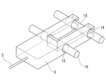
- FIG. 1 is an overall configuration diagram showing a medical stapler system according to an embodiment of the present invention. It is a figure which shows the case where the medical stapler system of FIG. 1 is a closed state. It is the longitudinal cross-sectional view which showed the front-end
- FIG. 2 is a longitudinal sectional view showing a state in which tissue is punctured into a staple in the medical stapler system of FIG. 1. It is a longitudinal cross-sectional view which shows the state which transfers the medical stapler which hold
- FIG. 6B is a longitudinal sectional view showing a state in which the staple portion of the staple is bent from the state of FIG. 6B.
- FIG. 6 is a transverse cross-sectional view showing a modified example of the medical stapler used in the medical stapler system of FIG. 1 and having a curved surface formed on the anvil portion. It is a cross-sectional view which shows the modification of the medical stapler system of FIG.
- the medical stapler system 1 includes a medical stapler 2 and staples 7 that are deformed by the medical stapler 2 and suture a tissue.
- the medical stapler 2 is provided so as to be openable and closable by a swing shaft, and a straight rod-like first gripping member 3 and second gripping the tissue A in the closed state.
- a gripping member 4, a holder 6 that accommodates the staple 7, and a drive mechanism 5 that slides the holder 6 along the longitudinal axis of the first gripping member 3 are provided.
- the first gripping member 3 includes a first contact surface 3 a that is brought into close contact with one side of the tissue A when closed, and a storage unit 10 that stores a holder 6 that holds the staple 7.
- the accommodating portion 10 is a recess opening in the first contact surface 3a.
- the needle portions 7a and 7b of the staple 7 are second from the first contact surface 3a. It arrange
- the second gripping member 4 includes a second contact surface 4a that is brought into close contact with the other side of the tissue A when closed, a recess 11 that receives the needle portion of the staple 7, and an anvil that presses and deforms the needle portion 7b. Part 8.
- the second gripping member 4 has a thickness dimension that does not allow the needle portions 7a and 7b of the staple 7 protruding from the first contact surface 3a to penetrate.
- the concave portion 11 has a size to be accommodated so as not to contact the needle portions 7a and 7b of the staple 7 even in the closed state.
- the first contact surface 3a of the first gripping member 3 and the second contact surfaces 4a of the second gripping member 4 located on the left and right sides across the recess 11 are parallel to each other in the closed state. The tissue A is grasped in the meantime.
- the first gripping member 3 and the second gripping member 4 are swung around the swinging axis with respect to the first gripping member 3 by the swinging mechanism 9. Are moved relative to each other between an open state opened mutually and a closed state closed as shown in FIG.
- the staple 7 includes a long base portion 7c, a first needle portion 7a extending from one end of the base portion 7c in a direction perpendicular to the longitudinal direction of the base portion 7c, It has an asymmetric shape having a second needle portion 7b extending from the other end of the base portion 7c in a direction orthogonal to the longitudinal direction of the base portion 7c.
- the second needle portion 7b is formed in a curved shape that smoothly curves in a direction in which the needle tip 7d approaches the first needle portion 7a.
- the needle tips 7d of the first needle portion 7a and the second needle portion 7b have sharp points that are easy to pierce the tissue A.
- a pin receiving portion 13 is provided at both ends of the base portion 7c to removably receive a fixing pin 18 described later.
- the staple 7 has a base portion 7 c of the staple 7 disposed in the holder 6 in a direction along the longitudinal axis of the first gripping member 3.
- the staple 7 sutures the tissue A by deforming the second needle portion 7b after the first needle portion 7a and the second needle portion 7b penetrate the tissue A. It is like that.
- a pair of linear first elongated holes 19 a extending in the longitudinal axis direction and penetrating through the accommodating portion, and the first elongated holes 19 a are formed on both side surfaces of the first gripping member 3.
- a pair of second long holes 19b that are provided on the proximal end side and are longer than the long axis of the first long hole 19a and penetrate the housing portion are formed.
- a fixing pin 18 is inserted into the pair of first long hole 19a and second long hole 19b in a direction intersecting the longitudinal axis of the first gripping member 3. It is like that.
- the holder 6 is formed with a groove for holding the base portion 7c of the staple 7, and an attachment / detachment mechanism 20 for switching between the state in which the staple 7 is held in the groove and the state in which the staple 7 is released is provided.
- the attachment / detachment mechanism 20 includes a pin hole 15 and a fitting recess 14 in which two fixing pins 18 are arranged in parallel in the groove of the holder 6 with a space in the longitudinal axis direction.
- the fixing pin 18 is accommodated in the pin hole 15 and both ends are accommodated in the second long hole 19b, and the fixing pin 18 is fitted in the fitting recess 14 and the both ends are accommodated in the first long hole 19a. .
- the staple 7 is released from the holder 6 when the fixing pin 18 is removed from the fitting recess 14.
- the holder 6 in which the staple 7 is fitted is accommodated in the accommodating portion 10 of the first gripping member 3, and as shown in FIGS. 3A and 3B, the first long hole 19 a and the second long hole of the first gripping member 3. From 19b, the fixing pin 18 is inserted so as to penetrate the fitting recess 14 and the pin hole 15 of the holder 6. Thus, the holder 6 is attached to the first gripping member 3 via the fixing pin 18 so as to be movable in the longitudinal axis direction.
- the drive mechanism 5 slides the holder 6 along the longitudinal axis direction in the housing portion 10 of the first gripping member 3, and is connected to the base end surface of the holder 6.
- the fixing pin 18 is disposed on the distal end side of the first long hole 19 a in the housing portion 10 of the first gripping member 3.
- the fixing pin 18 passes through the second position P2 (see FIG. 6B) where the fixing pin 18 is disposed on the proximal end side of the first long hole 19a, and the fixing pin 18 becomes the second long hole 19b. It is made to move between the third position P3 (refer to Drawing 6D) arranged at the base end side.
- the fixing pin 18 is limited to a range between the distal end portion of the first elongated hole 19a and the proximal end portion of the second elongated hole 19b in which the fixing pin 18 is movable.
- FIG. 6B In the state where the first gripping member 3 and the second gripping member 4 are in the open state and the holder 6 is disposed at the second position P2 by the drive mechanism 5, the second of the staple 7 is shown in FIG. 6B.
- the needle tip 7d of the needle portion 7b is disposed at a position corresponding to the anvil portion 8 of the second gripping member 4.
- an external force is applied in a direction in which the needle tip 7d of the second needle portion 7b abuts against the anvil portion 8 of the second gripping member 4 and strengthens the curve. (See FIG. 6C).
- the needle tip 7d of the second needle portion 7b is greatly bent and folded, and the tissue A is punctured again. It has become.
- the second needle portion 7b of the staple 7 is bent so as to embrace the tissue A, and the tissue A can be appropriately sutured.
- the holder 6 is further moved to the third position P3 on the base end side, whereby the fixing pin 18 is moved from the fitting recess 14.
- the staple 7 is released and released from the holder 6.
- the holder 6 is disposed at the first position P1 and the staple 7 is accommodated in the recess 11 (see FIG. 3B). Introduce to the vicinity of the affected part.
- the swing mechanism 9 is driven to swing the second gripping member 4 about the swing axis with respect to the first gripping member 3 so that the first gripping member 3 and the second gripping member 4 are opened to each other. Let it be the open state (refer FIG. 3A) opened mutually.
- the tissue A to be sutured is disposed between the first contact surface 3a of the first gripping member 3 and the second contact surface 4a of the second gripping member 4, and the swing mechanism 9 is operated to perform the first gripping.
- the member 3 and the second gripping member 4 are closed. Since the staple 7 is disposed on the distal end side of the first gripping member 3, the needle points of the first needle portion 7 a and the second needle portion 7 b of the staple 7 are in contact with the first contact surface 3 a of the first gripping member 3. It pierces and penetrates the tissue A gripped by the second contact surface 4a of the second gripping member 4 located on both the left and right sides with the recess 11 in between. Then, as shown in FIG. 6A, the swing mechanism 9 is actuated again to open the first gripping member 3 and the second gripping member 4.
- the needle tip 7d of the second needle portion 7b of the staple 7 is moved as shown in FIG. 6C.
- the needle tip 7d of the second needle part 7b is bent so as to be folded back to the tissue A side, and the tissue A is punctured again. Thereby, the tissue A can be firmly sutured by the staple 7.
- the holder 6 is further moved to the third position P3 on the proximal end side while the first gripping member 3 and the second gripping member 4 are in the closed state. Then, the fixing pin 18 disposed in the first long hole 19 a is stopped at the position of the base end portion of the first long hole 19 a and is removed from the fitting concave portion 14 provided at the front end side end portion of the holder 6. Then, the fixing pin 18 is also removed from the pin receiving portion 13 on the leading end side of the staple 7. At this time, the holder 6 moves until the fixing pin disposed in the second long hole 19b reaches the position of the proximal end of the second long hole 19b while leaving the staple 7 in the middle.
- the fixing pin 18 is also removed from the pin receiving portion 13 on the proximal end side, and the staple 7 is released from the holder 6.
- the swing mechanism 9 is driven to open the first gripping member 3 and the second gripping member 4 again.
- the released staple 7 is detached to the outside together with the sutured tissue A.
- the medical stapler system 1 when the medical stapler 2 is introduced into the body, even if the first gripping member 3 and the second gripping member 4 are in the closed state, Since the needle tip 7d of the staple 7 is not exposed to the outside, the medical stapler 2 can be safely introduced to the treatment site. Then, in a state where the medical stapler 2 is disposed in the body, the tissue A is sutured by the staple 7 by combining the opening and closing of the first gripping member 3 and the second gripping member 4 and the movement of the staple 7 in the longitudinal axis direction. can do. Therefore, it is not necessary to provide a space for protecting the needle tip 7d of the staple 7 from the outside in the medical stapler 2, and the medical stapler system 1 can be reduced in diameter.
- the tissue A is pressed against the first contact surface 3a of the first gripping member 3 by the second contact surfaces 4a of the second gripping member 4 located on both sides of the recess 11, so that the stable And can be sutured.
- the second needle portion 7b of the staple 7 is formed in a curved shape, when the pressing force is applied from the anvil portion 8 to bend the staple 7, the needle tip 7d of the second needle portion 7b becomes the tissue A.
- the tissue A can be appropriately sutured by being bent so as to be folded to the side.
- the staple 7 stitched with the tissue A can be easily released and discharged only by moving the holder 6 accommodated in the first gripping member 3 in the longitudinal axis direction.
- the holder 6 holds the staple 7 at the first position P1 where the second needle portion 7b of the staple 7 is accommodated in the concave portion 11, and the second needle portion 7b of the staple 7 is deformed by the anvil portion 8. Since the attachment / detachment mechanism 20 for releasing the staple 7 is provided at the third position P3, the tissue A can be removed from the medical stapler 2 simply by holding the staple at the first position P1 and releasing the staple 7 at the third position P3. Properly stitched staples 7 can be easily detached and discharged. *
- the anvil portion 8 of the second gripping member 4 is disposed adjacent to the concave portion 11 in the longitudinal axis direction, and the holder 6 is slid in the closed state. Accordingly, a curved surface 12 that guides and deforms the second needle portion 7b may be provided.
- the drive mechanism 5 is driven while the first gripping member 3 and the second gripping member 4 are closed, and the holder 6 holding the staple 7 is simply moved from the distal end side to the proximal end side.
- the tissue A can be sutured by bending the second needle portion 7b of the staple 7 along the curved surface.
- the pin receiving portion 13 that detachably receives the fixing pin 18 is described as an example provided on both ends of the base portion 7c of the staple 7, but instead of this, As shown in FIG. 5B, the pin receiving portion 13 is provided in a space defined by the upper surface of the base portion 7c and the outer surface of the first needle portion 7a, and the upper surface of the base portion 7c and the outer surface of the second needle portion 7b. Also good. Further, in the present embodiment, the staple 7 having a curved shape is employed so that the second needle portion 7b can be easily bent. Instead, as shown in FIG. 5C, the first needle is used. A target-shaped staple 7 having a straight second needle portion 7b having a mirror image relationship with the portion 7a may be employed.
- limits the moving range of the longitudinal direction of the holder 6 with the fixing pin 18 inserted through the 1st long hole 19a provided in the 1st holding member 3 and the 2nd long hole 19b
- the holder 6 is provided with a protrusion 16 on the bottom surface of the holder 6 and a groove 17 that fits the protrusion 16 on the inner surface of the first gripping member 3.
- the positioning and movement range may be regulated.
- the fixing pin 18 may be formed of plastic or the like that can be deformed by an external force, or an elastic material such as a spring may be connected to the fixing pin 18 to hold the staple 7 in the holder 6.
- an elastic material such as a spring
- tissue A can be made still easier.
- a protrusion or the like that makes it difficult for the staple 7 to fall off may be provided on the side surface of the groove of the holder 6 in which the base portion 7c of the staple 7 is fitted.
- the present embodiment has exemplified the case where one staple 7 is arranged in the direction along the longitudinal axis direction.
- the number of staples 7 and the number of rows may be arbitrary. .
Abstract
ステープルの針先を外部から保護するためのスペースを確保しながら細径化する。本発明に係る医療用ステープラシステム1は、医療用ステープラ2と、組織Aを縫合するステープル7とを備える。医療用ステープラ2は、閉状態において間に組織Aを把持可能な長手軸を有する第1把持部材3および第2把持部材4と、ステープル7を保持するホルダ6と、第1把持部材3の第1接触面3aからステープル7の針部7aを突出させた状態でホルダ6を収容する収容部10と、ホルダ6を長手軸に沿ってスライドさせる駆動機構5とを備える。第1接触面3aとの間に組織Aを把持する第2把持部材4の第2接触面4aに、ホルダ6が長手軸方向のいずれか一方に配置されかつ閉状態となったときに針部7aを貫通および変形させることなく収容可能な凹部11と、ホルダ6が長手軸方向の他方に配置されかつ閉状態となったときに針部7aを変形させるアンビル部8とを備えている。
Description
本発明は、医療用ステープラシステムに関するものである。
一対のジョーの間に組織を把持し、一方のジョーからステープルを打ち出して、他方のジョーによりステープルを変形させる医療用ステープラが知られている(例えば、特許文献1参照。)。
また、組織を把持する一対のジョーの内部に、複数のステープルが配列されたカートリッジを装着し、ジョーを閉鎖することでステープルを変形させる医療用ステープラも知られている(例えば、特許文献2参照。)。
また、組織を把持する一対のジョーの内部に、複数のステープルが配列されたカートリッジを装着し、ジョーを閉鎖することでステープルを変形させる医療用ステープラも知られている(例えば、特許文献2参照。)。
特許文献1や特許文献2の医療用ステープラでは、一対のジョーのうち、下方のジョーに装着されたステープルをステープラの長手軸方向に対して垂直な方向に押し出し、上方のジョーのアンビルに押し当てて変形させることにより組織を縫合する仕組みとなっている。ステープルを格納したステープラを処置部位まで導入する際や縫合前には、体腔内を傷つけないためにステープルの針先がアンビルよりも外部に露出しないようにする必要がある。したがって、針先を外部から保護するためのスペースを確保する必要があり、その分だけステープラが太径となるので、医療用ステープラシステムを細径化することは困難となる。
本発明は上述した事情に鑑みてなされたものであって、ステープルの針先を外部から保護するためのスペースを確保しながら細径化することができる医療用ステープラシステムを提供することを目的としている。
本発明は上述した事情に鑑みてなされたものであって、ステープルの針先を外部から保護するためのスペースを確保しながら細径化することができる医療用ステープラシステムを提供することを目的としている。
本発明の一態様は、医療用ステープラと、該医療用ステープラにより変形させられて組織を縫合するステープルとを備え、前記医療用ステープラが、揺動可能に連結されて相互に開閉可能に設けられ、閉状態において間に組織を把持可能な長手軸を有する第1把持部材および第2把持部材と、前記ステープルを保持するホルダと、前記閉状態において前記組織に密着させられる前記第1把持部材の第1接触面から前記ステープルの針部を突出させた状態で前記ホルダを収容する収容部と、該収容部内において前記ホルダを前記長手軸に沿ってスライドさせる駆動機構とを備え、前記閉状態において前記第1接触面との間に前記組織を把持する前記第2把持部材の第2接触面に、前記ホルダが前記長手軸方向のいずれか一方に配置されかつ前記閉状態となったときに前記針部を貫通および変形させることなく収容可能な凹部と、前記ホルダが前記長手軸方向の他方に配置されかつ前記閉状態となったときに前記針部を突き当てて変形させるアンビル部とを備える医療用ステープラシステムである。
本態様によれば、ステープルを保持したホルダを長手軸方向のいずれか一方に配置して医療用ステープラの第1把持部材と第2把持部材を閉状態とすると、ステープルの針部がちょうど第2把持部材の凹部に収容される。したがって、医療用ステープラを体内に導入していく場合に、第1把持部材と第2把持部材とを閉状態としても、ステープルの針先が外部に露出しないため、医療用ステープラを安全に処置部位にまで導入させることができる。そして、医療用ステープラが体内に配置された状態で、第1把持部材と第2把持部材との開閉およびステープルの長手軸方向への移動を組み合わせて、ステープルによって組織を縫合することができる。
一方、駆動機構を作動させてホルダを長手軸方向の他方にスライドさせると、ステープルの針部が第2把持部材のアンビル部に対向する位置に配置されるので、第1把持部材と第2把持部材とを閉状態とすることにより、針部をアンビル部に突き当てて変形させ、組織を縫合することができる。
その結果、針先を外部から保護するためのスペースを医療用ステープラに別途設ける必要がなく、医療用ステープラを細径化することができ、内視鏡チャネルや外科用トロカーのような限られた内径のアクセスポートを通して医療用ステープラシステムを用いて処置部位まで容易にデリバリすることができる。
その結果、針先を外部から保護するためのスペースを医療用ステープラに別途設ける必要がなく、医療用ステープラを細径化することができ、内視鏡チャネルや外科用トロカーのような限られた内径のアクセスポートを通して医療用ステープラシステムを用いて処置部位まで容易にデリバリすることができる。
上記態様においては、前記ステープルが、長尺形状のベース部を備え、前記針部が、前記ベース部の一端からベース部の長尺方向に直交する方向に延びる鋭利な形状に形成された第1針部と、前記ベース部の他端からベース部の長尺方向に直交する方向に延びるとともに、その針先が前記第1針部に近接する方向に滑らかに湾曲する曲線状に形成された第2針部7bとを有し、前記ステープルが、前記ベース部を前記医療用ステープラ2の長手軸方向に沿わせて配置されることとしてもよい。
このようにすることで、ステープルのベース部が医療用ステープラの長手軸方向に沿わせて配置されるため、ステープルのベース部を医療用ステープラの長手軸方向に直交する方向に配置される場合に比べ、医療用ステープラの直径を小さくすることができ、したがって、医療用ステープラシステムを細径化することができる。
また、ステープルの第2針部が滑らかに湾曲する曲線状に形成されているので、アンビル部により第2針部を押圧すると、第2針部の針先が第1針部側に向かって倒れるように大きく湾曲して組織を抱き込むように穿刺させられる。これにより、ステープルによって組織をしっかりと縫合することができる。
また、ステープルの第2針部が滑らかに湾曲する曲線状に形成されているので、アンビル部により第2針部を押圧すると、第2針部の針先が第1針部側に向かって倒れるように大きく湾曲して組織を抱き込むように穿刺させられる。これにより、ステープルによって組織をしっかりと縫合することができる。
上記態様においては、前記アンビル部が、前記凹部に前記長手軸方向に隣接して配置されるとともに、前記閉状態において前記ホルダをスライドさせることにより、前記第2針部を案内して湾曲変形させる湾曲面が設けられていてもよい。
このようにすることで、医療用ステープラの第1把持部材および第2把持部材を閉状態としたままステープルが保持されたホルダを基端側にスライドさせるだけで、ステープルの第2針部をアンビル部の湾曲面によって湾曲させて組織を縫合することができる。
このようにすることで、医療用ステープラの第1把持部材および第2把持部材を閉状態としたままステープルが保持されたホルダを基端側にスライドさせるだけで、ステープルの第2針部をアンビル部の湾曲面によって湾曲させて組織を縫合することができる。
上記態様においては、前記ホルダが、前記ステープルの前記針部が前記凹部に収容されている位置で前記ステープルを保持し、前記ステープルの前記針部が前記アンビル部により変形された位置で、前記ステープルを解放する着脱機構を備えていてもよい。
このようにすることで、着脱機構により、ホルダがステープルの針部が凹部に収容されている位置でステープルを保持し、ステープルの針部がアンビル部により変形された位置で、ステープルを解放するだけで、医療用ステープラから組織を適正に縫合したステープルを容易に離脱させて排出させることができる。
本発明によれば、ステープルの針先を外部から保護するためのスペースを確保しながら細径化することができる医療用ステープラシステムを提供できるという効果を奏する。
本発明の一実施形態に係る医療用ステープラシステム1について、図面を参照して以下に説明する。
本実施形態に係る医療用ステープラシステム1は、図1に示されるように、医療用ステープラ2と、該医療用ステープラ2により変形させられて組織を縫合するステープル7とを備えている。
本実施形態に係る医療用ステープラシステム1は、図1に示されるように、医療用ステープラ2と、該医療用ステープラ2により変形させられて組織を縫合するステープル7とを備えている。
医療用ステープラ2は、図1および図2に示されるように、揺動軸によって相互に開閉可能に設けられ、閉状態において間に組織Aを把持する直棒状の第1把持部材3および第2把持部材4と、ステープル7を収容するホルダ6と、該ホルダ6を第1把持部材3の長手軸に沿ってスライドさせる駆動機構5とを備えている。第1把持部材3は、閉状態にしたときに組織Aの一側に密着させられる第1接触面3aと、ステープル7を保持するホルダ6を収容する収容部10を備えている。
収容部10は第1接触面3aに開口する凹部であり、該収容部10内にステープル7を保持したホルダ6を収容すると、ステープル7の針部7a,7bが第1接触面3aから第2把持部材4側に尖端を向けて突出した状態に配置されるようになっている(図3A参照)。
第2把持部材4は、閉状態にしたときに組織Aの他側に密着させられる第2接触面4aと、ステープル7の針部を受け入れる凹部11と、針部7bを押し当てて変形させるアンビル部8とを備えている。
第2把持部材4は、閉状態にしたときに組織Aの他側に密着させられる第2接触面4aと、ステープル7の針部を受け入れる凹部11と、針部7bを押し当てて変形させるアンビル部8とを備えている。
また、第2把持部材4は、図3Bに示されるように、第1接触面3aから突出しているステープル7の針部7a、7bを貫通させない厚さ寸法を有している。また、凹部11は、閉状態においてもステープル7の針部7a、7bに接触しないように収容する寸法を有している。
図3Cに示されるように、第1把持部材3の第1接触面3aと、凹部11を挟んで左右両側に位置する第2把持部材4の第2接触面4aとは、閉状態において互いに平行に対向し、その間に組織Aが把持されるようになっている。
図3Cに示されるように、第1把持部材3の第1接触面3aと、凹部11を挟んで左右両側に位置する第2把持部材4の第2接触面4aとは、閉状態において互いに平行に対向し、その間に組織Aが把持されるようになっている。
第1把持部材3と第2把持部材4とは、揺動機構9によって第2把持部材4を第1把持部材3に対して揺動軸回りに揺動させることで、図1に示されるように相互に開いた開状態と、図2に示されるように相互に閉じられて間に組織Aを把持する閉状態との間で相対的に移動させられるようになっている。
ステープル7は、例えば、図5Aに示されるように、長尺形状のベース部7cと、該ベース部7cの一端からベース部7cの長尺方向に直交する方向に延びる第1針部7aと、ベース部7cの他端からベース部7cの長尺方向に直交する方向に延びる第2針部7bとを有する非対称形状を有している。第2針部7bは、その針先7dが第1針部7aに近接する方向に滑らかに湾曲する曲線状に形成されている。第1針部7aおよび第2針部7bの針先7dは、組織Aに刺さり易い鋭利な尖端を有している。図5Aに示されるように、ベース部7cの両端には、後述する固定ピン18を着脱可能に受け取るピン受け部13が設けられている。
ステープル7は、図1および図2に示されるように、ホルダ6内において、ステープル7のベース部7cが第1把持部材3の長手軸に沿う方向に配置されている。
図6Aから図6Dに示されるように、ステープル7は、第1針部7aおよび第2針部7bが組織Aを貫通した後に、第2針部7bを変形させることにより、組織Aを縫合するようになっている。
図6Aから図6Dに示されるように、ステープル7は、第1針部7aおよび第2針部7bが組織Aを貫通した後に、第2針部7bを変形させることにより、組織Aを縫合するようになっている。
第1把持部材3の両側面には、図1から図3Bに示されるように、長手軸方向に延び収容部に貫通する直線状の一対の第1長孔19aと、該第1長孔19aよりも基端側に設けられ、かつ第1長孔19aの長軸よりも長く、収容部に貫通する一対の第2長孔19bと、が形成されている。そして、図3Aおよび図3Bに示されるように、これら一対の第1長孔19aおよび第2長孔19bにはそれぞれ、第1把持部材3の長手軸に交差する方向に固定ピン18が差し込まれるようになっている。
ホルダ6には、図4Bに示されるように、ステープル7のベース部7cを保持する溝が形成されているとともに、この溝にステープル7を保持した状態と解放した状態とに切り替える着脱機構20を備えている。
着脱機構20は、図4Aおよび図4Bに示されるように、ホルダ6の溝に2本の固定ピン18を長手軸方向に間隔をあけて平行に配置するピン孔15および嵌合凹部14と、ピン孔15に収容されかつ第2長孔19bに両端が収容される固定ピン18および嵌合凹部14に嵌合されかつ第1長孔19aに両端が収容される固定ピン18とを備えている。固定ピン18が嵌合凹部14から外れることにより、ステープル7がホルダ6から解放されるようになっている。
着脱機構20は、図4Aおよび図4Bに示されるように、ホルダ6の溝に2本の固定ピン18を長手軸方向に間隔をあけて平行に配置するピン孔15および嵌合凹部14と、ピン孔15に収容されかつ第2長孔19bに両端が収容される固定ピン18および嵌合凹部14に嵌合されかつ第1長孔19aに両端が収容される固定ピン18とを備えている。固定ピン18が嵌合凹部14から外れることにより、ステープル7がホルダ6から解放されるようになっている。
ステープル7が嵌め込まれたホルダ6は、第1把持部材3の収容部10に収容され、図3Aおよび図3Bに示されるように、第1把持部材3の第1長孔19aおよび第2長孔19bから、ホルダ6の嵌合凹部14およびピン孔15を貫通するようにして固定ピン18が差し込まれている。これにより、ホルダ6は、固定ピン18を介して第1把持部材3に長手軸方向に移動可能に取り付けられている。
駆動機構5は、第1把持部材3の収容部10内において、ホルダ6を長手軸方向に沿ってスライドさせるものであり、ホルダ6の基端面に接続されている。この駆動機構5に長手軸方向の押圧力を印加することにより、ホルダ6が第1把持部材3の収容部10内において、固定ピン18が第1長孔19aの先端側に配置されている第1位置P1(図6A参照)から固定ピン18が第1長孔19aの基端側に配置されている第2位置P2(図6B参照)を経由して、固定ピン18が第2長孔19bの基端側に配置されている第3位置P3(図6D参照)との間で移動させられるようになっている。ホルダ6は第1長孔19aおよび第2長孔19bを介して固定ピン18により第1把持部材3に固定されているので、ホルダ6の長手軸方向の移動は、図3Aおよび図3Bに示されるように、固定ピン18が移動可能である第1長孔19aの先端部から第2長孔19b基端部の間の範囲に制限される。
第1把持部材3と第2把持部材4とを閉状態とし、駆動機構5によりホルダ6を第1把持部材3の最も先端側の第1位置P1に配置させた状態では、図2および図3Bに示されるように、組織Aを貫通したステープル7の第2針部7bの針先7dが第2把持部材4の凹部11内側に位置する。したがって、閉状態としても、ステープル7の針先7dが外部に露出しないようになっている。
また、第1把持部材3と第2把持部材4とを開状態とし、駆動機構5によりホルダ6を第2位置P2に配置させた状態では、図6Bに示されるように、ステープル7の第2針部7bの針先7dが、第2把持部材4のアンビル部8に対応する位置に配置される。この状態で第1把持部材3と第2把持部材4とを閉状態とすると、第2針部7bの針先7dが第2把持部材4のアンビル部8に突き当たって湾曲を強める方向に外力を受けるようになっている(図6C参照)。
第2把持部材4のアンビル部8からの外力をさらに受けると、図6Dに示されるように、第2針部7bの針先7dが大きく湾曲されて折り返され、組織Aに再度穿刺させられるようになっている。このように、ステープル7の第2針部7bが組織Aを抱き込むように湾曲させられて、組織Aを適正に縫合することができるようになっている。
そして、この後に第1把持部材3と第2把持部材4とを閉状態としたまま、ホルダ6をさらに基端側の第3位置P3に移動させることにより、固定ピン18が嵌合凹部14から外れてステープル7がホルダ6から解放されるようになっている。
このように構成された本実施形態に係る医療用ステープラシステム1の作用について以下に説明する。
本実施形態に係る医療用ステープラシステム1を用いて組織Aを縫合するには、まず、ホルダ6を第1位置P1に配置してステープル7が凹部11に収容された閉状態(図3B参照)として患部近傍まで導入する。次いで、揺動機構9を駆動させ、第2把持部材4を第1把持部材3に対して揺動軸回りに揺動させて第1把持部材3および第2把持部材4が相互に開かれた相互に開いた開状態(図3A参照)とする。
本実施形態に係る医療用ステープラシステム1を用いて組織Aを縫合するには、まず、ホルダ6を第1位置P1に配置してステープル7が凹部11に収容された閉状態(図3B参照)として患部近傍まで導入する。次いで、揺動機構9を駆動させ、第2把持部材4を第1把持部材3に対して揺動軸回りに揺動させて第1把持部材3および第2把持部材4が相互に開かれた相互に開いた開状態(図3A参照)とする。
その後、第1把持部材3の第1接触面3aと第2把持部材4の第2接触面4aとの間に、縫合したい組織Aを配置して、揺動機構9を作動させて第1把持部材3と第2把持部材4とを閉状態とする。第1把持部材3の先端側には、ステープル7が配置されているので、ステープル7の第1針部7aと第2針部7bの針先が第1把持部材3の第1接触面3aと凹部11を挟んで左右両側に位置する第2把持部材4の第2接触面4aとで把持した組織Aに突き刺さって貫通する。そして、図6Aに示されるように、揺動機構9を再度作動させて第1把持部材3と第2把持部材4とを開状態とする。
この状態で、駆動機構5に、ステープル7が保持されたホルダ6を第1把持部材3の基端側に移動させる駆動力を加え、第1把持部材3に設けられた第1長孔19aおよび第2長孔19bに沿ってホルダ6を、固定ピン18が第1長孔19aの基端側に配置される第2位置P2まで移動させる(図6B)。
次いで、揺動機構9を作動させて、第2把持部材4と第1把持部材3とを閉状態とすると、図6Cに示されるように、ステープル7の第2針部7bの針先7dが、アンビル部8に突き当たって外力を受けることで、第2針部7bの針先7dが組織A側に折り返されるように湾曲させられて、再度組織Aに穿刺させられる。これにより、ステープル7によって組織Aをしっかりと縫合することができる。
さらに、この状態から、図6Dに示されるように、第1把持部材3と第2把持部材4とを閉状態としたまま、ホルダ6をさらに基端側の第3位置P3に移動させる。すると、第1長孔19aに配置される固定ピン18は、第1長孔19aの基端部の位置で停止させられて、ホルダ6の先端側端部に設けられた嵌合凹部14から外され、ステープル7の先端側のピン受け部13からも固定ピン18が外される。その際、ホルダ6は、ステープル7を途中に取り残したまま、第2長孔19bに配置される固定ピンが第2長孔19bの基端部の位置に到達するまで移動するので、ステープル7の基端側のピン受け部13からも固定ピン18が外され、ステープル7がホルダ6から解放される。
次いで、揺動機構9を駆動させて第1把持部材3と第2把持部材4とを再び開状態とする。解放されたステープル7は、縫合された組織Aとともに外部に離脱される。
次いで、揺動機構9を駆動させて第1把持部材3と第2把持部材4とを再び開状態とする。解放されたステープル7は、縫合された組織Aとともに外部に離脱される。
このように、本実施形態に係る医療用ステープラシステム1によれば、医療用ステープラ2を体内に導入していく場合に、第1把持部材3と第2把持部材4とを閉状態としても、ステープル7の針先7dが外部に露出しないため、医療用ステープラ2を安全に処置部位にまで導入することができる。そして、医療用ステープラ2が体内に配置された状態で、第1把持部材3と第2把持部材4との開閉およびステープル7の長手軸方向への移動を組み合わせて、ステープル7によって組織Aを縫合することができる。したがって、ステープル7の針先7dを外部から保護するためのスペースを別途医療用ステープラ2に設ける必要がなく、医療用ステープラシステム1を細径化することができるという効果を奏する。
また、穿刺時には、凹部11を挟んで両側に位置する第2把持部材4の第2接触面4aにより、組織Aを第1把持部材3の第1接触面3aに逃げないように押さえつけるので、安定して縫合することができる。また、ステープル7の第2針部7bが湾曲する曲線状に形成されているので、アンビル部8から押圧力を与えてステープル7を湾曲させると、第2針部7bの針先7dが組織A側に折り返されるように湾曲させられて組織Aを適正に縫合することができる。
また、第1把持部材3に収容したホルダ6を長手軸方向に移動させるだけで、組織Aを縫合したステープル7を容易に解放させて排出させることができる。
また、第1把持部材3に収容したホルダ6を長手軸方向に移動させるだけで、組織Aを縫合したステープル7を容易に解放させて排出させることができる。
また、ホルダ6が、ステープル7の第2針部7bが凹部11に収容されている第1位置P1でステープル7を保持し、ステープル7の第2針部7bがアンビル部8により変形された第3位置P3で、ステープル7を解放する着脱機構20を備えているので、第1位置P1でステープルを保持し、第3位置P3でステープル7を解放するだけで、医療用ステープラ2から組織Aを適正に縫合したステープル7を容易に離脱させて排出させることができる。
なお、本実施形態では、図7に示されるように、第2把持部材4のアンビル部8には、凹部11に長手軸方向に隣接して配置されるとともに、閉状態においてホルダ6をスライドさせることにより、第2針部7bを案内して湾曲変形させる湾曲面12を設けていてもよい。
このようにすることで、第1把持部材3および第2把持部材4を閉状態としたまま駆動機構5を駆動させてステープル7が保持されたホルダ6を先端側から基端側に移動させるだけで、ステープル7の第2針部7bを湾曲面に沿って湾曲させて組織Aを縫合することができる。
このようにすることで、第1把持部材3および第2把持部材4を閉状態としたまま駆動機構5を駆動させてステープル7が保持されたホルダ6を先端側から基端側に移動させるだけで、ステープル7の第2針部7bを湾曲面に沿って湾曲させて組織Aを縫合することができる。
また、本実施形態においては、固定ピン18を着脱可能に受けるピン受け部13が、ステープル7のベース部7cの両端に設けられた物を例示して説明しているが、これに代えて、図5Bに示されるように、ピン受け部13をベース部7cの上面と第1針部7aの外面および、ベース部7cの上面と第2針部7bの外面により規定される空間に設けることとしてもよい。
また、本実施形態においては、第2針部7bが湾曲されやすいように、曲線状に湾曲した形態のステープル7を採用したが、これに代えて、図5Cに示されるように、第1針部7aと鏡像関係にある真っ直ぐな第2針部7bを有する対象形状のステープル7を採用してもよい。
また、本実施形態においては、第2針部7bが湾曲されやすいように、曲線状に湾曲した形態のステープル7を採用したが、これに代えて、図5Cに示されるように、第1針部7aと鏡像関係にある真っ直ぐな第2針部7bを有する対象形状のステープル7を採用してもよい。
また、本実施形態においては、第1把持部材3に設けた第1長孔19aおよび第2長孔19bを介して挿入された固定ピン18によりホルダ6の長手軸方向の移動範囲を制限する例について説明したが、これに代えて、図8に示されるように、ホルダ6の底面に突起16を設け、これと嵌合する溝17を第1把持部材3の内面に設けることで、ホルダ6の位置決めと移動範囲の規制をするようにしてもよい。
また、固定ピン18を、外力により変形可能なプラスチック等により形成したり、固定ピン18にばねなどの弾性材料を接続するなどしてホルダ6内にステープル7を保持することとしてもよい。このようにすることで、組織Aを縫合したステープル7の排出をさらに容易にすることができる。
また、ステープル7のベース部7cが嵌め込まれるホルダ6の溝の側面に、ステープル7を抜け落ちにくくする突起等を設けてもよい。
また、ステープル7のベース部7cが嵌め込まれるホルダ6の溝の側面に、ステープル7を抜け落ちにくくする突起等を設けてもよい。
なお、図示および説明を簡易にするために、本実施形態では1つのステープル7を長手軸方向に沿う方向に配置した場合を例示したが、ステープル7の数および列数は任意の数としてかまわない。
1 医療用ステープラシステム
2 医療用ステープラ
3 第1把持部材
4 第2把持部材
5 駆動機構
6 ホルダ
7 ステープル
7a 第1針部(針部)
7b 第2針部(針部)
7c ベース部
8 アンビル部
10 収容部
11 凹部
12 湾曲面
13 ピン受け部
18 固定ピン
19a 第1長孔
19b 第2長孔
20 着脱機構
A 組織
P1 第1位置
P2 第2位置
P3 第3位置
2 医療用ステープラ
3 第1把持部材
4 第2把持部材
5 駆動機構
6 ホルダ
7 ステープル
7a 第1針部(針部)
7b 第2針部(針部)
7c ベース部
8 アンビル部
10 収容部
11 凹部
12 湾曲面
13 ピン受け部
18 固定ピン
19a 第1長孔
19b 第2長孔
20 着脱機構
A 組織
P1 第1位置
P2 第2位置
P3 第3位置
Claims (4)
- 医療用ステープラと、
該医療用ステープラにより変形させられて組織を縫合するステープルとを備え、
前記医療用ステープラが、揺動可能に連結されて相互に開閉可能に設けられ、閉状態において間に前記組織を把持可能な長手軸を有する第1把持部材および第2把持部材と、前記ステープルを保持するホルダと、前記閉状態において前記組織に密着させられる前記第1把持部材の第1接触面から前記ステープルの針部を突出させた状態で前記ホルダを収容する収容部と、該収容部内において前記ホルダを前記長手軸に沿ってスライドさせる駆動機構とを備え、
前記閉状態において前記第1接触面との間に前記組織を把持する前記第2把持部材の第2接触面に、前記ホルダが前記長手軸方向のいずれか一方に配置されかつ前記閉状態となったときに前記針部を貫通および変形させることなく収容可能な凹部と、前記ホルダが前記長手軸方向の他方に配置されかつ前記閉状態となったときに前記針部を突き当てて変形させるアンビル部とを備える医療用ステープラシステム。 - 前記ステープルが、長尺形状のベース部を備え、
前記針部が、前記ベース部の一端から該ベース部の長尺方向に直交する方向に延びる鋭利な形状に形成された第1針部と、前記ベース部の他端から該ベース部の長尺方向に直交する方向に延びるとともに、その針先が前記第1針部に近接する方向に滑らかに湾曲する曲線状に形成された第2針部とを有し、
前記ステープルが、前記ベース部を前記医療用ステープラの前記長手軸方向に沿わせて配置される請求項1に記載の医療用ステープラシステム。 - 前記アンビル部が、前記凹部に前記長手軸方向に隣接して配置されるとともに、前記閉状態において前記ホルダをスライドさせることにより、前記第2針部を案内して湾曲変形させる湾曲面を備える請求項2に記載の医療用ステープラシステム。
- 前記ホルダが、前記ステープルの前記針部が前記凹部に収容されている位置で前記ステープルを保持し、前記ステープルの前記針部が前記アンビル部により変形された位置で、前記ステープルを解放する着脱機構を備える請求項1から請求項3のいずれかに記載の医療用ステープラシステム。
Priority Applications (3)
| Application Number | Priority Date | Filing Date | Title |
|---|---|---|---|
| JP2018550969A JP6803395B2 (ja) | 2016-11-18 | 2016-11-18 | 医療用ステープラシステム |
| PCT/JP2016/084293 WO2018092273A1 (ja) | 2016-11-18 | 2016-11-18 | 医療用ステープラシステム |
| US16/299,439 US10881400B2 (en) | 2016-11-18 | 2019-03-12 | Medical stapler system |
Applications Claiming Priority (1)
| Application Number | Priority Date | Filing Date | Title |
|---|---|---|---|
| PCT/JP2016/084293 WO2018092273A1 (ja) | 2016-11-18 | 2016-11-18 | 医療用ステープラシステム |
Related Child Applications (1)
| Application Number | Title | Priority Date | Filing Date |
|---|---|---|---|
| US16/299,439 Continuation US10881400B2 (en) | 2016-11-18 | 2019-03-12 | Medical stapler system |
Publications (1)
| Publication Number | Publication Date |
|---|---|
| WO2018092273A1 true WO2018092273A1 (ja) | 2018-05-24 |
Family
ID=62146264
Family Applications (1)
| Application Number | Title | Priority Date | Filing Date |
|---|---|---|---|
| PCT/JP2016/084293 WO2018092273A1 (ja) | 2016-11-18 | 2016-11-18 | 医療用ステープラシステム |
Country Status (3)
| Country | Link |
|---|---|
| US (1) | US10881400B2 (ja) |
| JP (1) | JP6803395B2 (ja) |
| WO (1) | WO2018092273A1 (ja) |
Cited By (1)
| Publication number | Priority date | Publication date | Assignee | Title |
|---|---|---|---|---|
| US11896232B2 (en) | 2021-11-24 | 2024-02-13 | Cilag Gmbh International | Tissue stabilizing features for circular surgical stapler |
Citations (4)
| Publication number | Priority date | Publication date | Assignee | Title |
|---|---|---|---|---|
| JPS4865091U (ja) * | 1971-11-24 | 1973-08-17 | ||
| JPH07124166A (ja) * | 1993-11-02 | 1995-05-16 | Olympus Optical Co Ltd | 縫合装置 |
| JP2005160933A (ja) * | 2003-12-05 | 2005-06-23 | Nisca Corp | 医療用ステープラ |
| US20160058441A1 (en) * | 2014-09-02 | 2016-03-03 | Ethicon Endo-Surgery, Inc. | Devices and Methods for Facilitating Ejection of Surgical Fasteners from Cartridges |
Family Cites Families (75)
| Publication number | Priority date | Publication date | Assignee | Title |
|---|---|---|---|---|
| JPS517431B2 (ja) | 1971-12-15 | 1976-03-08 | ||
| SU982676A1 (ru) | 1981-04-07 | 1982-12-23 | Всесоюзный научно-исследовательский и испытательный институт медицинской техники | Хирургическа скобка |
| DE4014653A1 (de) | 1990-05-08 | 1991-11-14 | Beiersdorf Ag | Chirurgische klammer |
| NL9100174A (nl) | 1991-02-01 | 1992-09-01 | Philips Nv | Kleurenbeeld-weergeefinrichting en kleurencamera. |
| CA2133687C (en) | 1992-10-09 | 2007-03-27 | David T. Green | Surgical clip applier |
| US5779718A (en) | 1992-10-09 | 1998-07-14 | United States Surgical Corporation | Method of anastomosing a vessel using a surgical clip applier |
| US5868761A (en) | 1992-10-09 | 1999-02-09 | United States Surgical Corporation | Surgical clip applier |
| CA2107635C (en) | 1992-10-09 | 1999-08-17 | David T. Green | Surgical clip applier |
| WO1994020030A1 (en) | 1993-03-02 | 1994-09-15 | Cook Melvin S | Improved staples |
| US5342396A (en) | 1993-03-02 | 1994-08-30 | Cook Melvin S | Staples |
| US5456400A (en) * | 1993-04-22 | 1995-10-10 | United States Surgical Corporation | Apparatus and clip for fastening body tissue |
| US5843084A (en) * | 1995-11-17 | 1998-12-01 | Innovasive Devices, Inc. | Surgical fastening system and method for using the same |
| US6099537A (en) | 1996-02-26 | 2000-08-08 | Olympus Optical Co., Ltd. | Medical treatment instrument |
| JPH09224944A (ja) | 1996-02-26 | 1997-09-02 | Olympus Optical Co Ltd | 縫合・結紮具 |
| JP3200049B2 (ja) | 1999-07-09 | 2001-08-20 | 博 安永 | 皮膚縫合用ステープル |
| US7063712B2 (en) * | 2001-04-27 | 2006-06-20 | Cardica, Inc. | Anastomosis method |
| FR2804597B1 (fr) | 2000-02-04 | 2002-04-26 | Soprane Sa | Aiguille hyper-elastique |
| US6306149B1 (en) * | 2000-02-15 | 2001-10-23 | Microline, Inc. | Medical clip device with cyclical pusher mechanism |
| US20040267310A1 (en) | 2000-10-20 | 2004-12-30 | Racenet David C | Directionally biased staple and anvil assembly for forming the staple |
| JP4526206B2 (ja) | 2001-04-25 | 2010-08-18 | 株式会社トップ | 外科用ステープル |
| US10285694B2 (en) | 2001-10-20 | 2019-05-14 | Covidien Lp | Surgical stapler with timer and feedback display |
| JP4464816B2 (ja) | 2002-06-14 | 2010-05-19 | パワー メディカル インターベンションズ, エルエルシー | 外科用デバイス |
| US6925849B2 (en) | 2002-09-10 | 2005-08-09 | Acco Brands, Inc. | Stapler anvil |
| JP2004097714A (ja) | 2002-09-13 | 2004-04-02 | Keio Gijuku | 手術用縫合針 |
| US8627992B2 (en) * | 2002-12-16 | 2014-01-14 | Edrich Health Technologies, Inc. | Endovascular stapler |
| US8449560B2 (en) | 2004-03-09 | 2013-05-28 | Satiety, Inc. | Devices and methods for placement of partitions within a hollow body organ |
| US8628547B2 (en) | 2004-03-09 | 2014-01-14 | Ethicon Endo-Surgery, Inc. | Devices and methods for placement of partitions within a hollow body organ |
| US9028511B2 (en) | 2004-03-09 | 2015-05-12 | Ethicon Endo-Surgery, Inc. | Devices and methods for placement of partitions within a hollow body organ |
| US8252009B2 (en) | 2004-03-09 | 2012-08-28 | Ethicon Endo-Surgery, Inc. | Devices and methods for placement of partitions within a hollow body organ |
| US7722610B2 (en) | 2005-06-02 | 2010-05-25 | Tyco Healthcare Group Lp | Multiple coil staple and staple applier |
| EP1917125B1 (en) | 2005-07-27 | 2011-09-07 | Tyco Healthcare Group LP | Staple pocket arrangement for surgical stapler |
| US7407078B2 (en) | 2005-09-21 | 2008-08-05 | Ehthicon Endo-Surgery, Inc. | Surgical stapling instrument having force controlled spacing end effector |
| US7357287B2 (en) | 2005-09-29 | 2008-04-15 | Ethicon Endo-Surgery, Inc. | Surgical stapling instrument having preloaded firing assistance mechanism |
| US8292920B2 (en) | 2005-11-10 | 2012-10-23 | Tyco Healthcare Group Lp | Sickle needle and method |
| US8322455B2 (en) | 2006-06-27 | 2012-12-04 | Ethicon Endo-Surgery, Inc. | Manually driven surgical cutting and fastening instrument |
| US8220690B2 (en) | 2006-09-29 | 2012-07-17 | Ethicon Endo-Surgery, Inc. | Connected surgical staples and stapling instruments for deploying the same |
| US10130359B2 (en) | 2006-09-29 | 2018-11-20 | Ethicon Llc | Method for forming a staple |
| US10568652B2 (en) | 2006-09-29 | 2020-02-25 | Ethicon Llc | Surgical staples having attached drivers of different heights and stapling instruments for deploying the same |
| EP2103262B1 (en) | 2007-01-11 | 2013-02-27 | Mani, Inc. | Suturing needle |
| AU2008231109B2 (en) | 2007-03-22 | 2013-01-10 | Covidien Lp | Apparatus for forming variable height surgical fasteners |
| US8157145B2 (en) | 2007-05-31 | 2012-04-17 | Ethicon Endo-Surgery, Inc. | Pneumatically powered surgical cutting and fastening instrument with electrical feedback |
| US7988026B2 (en) * | 2007-09-06 | 2011-08-02 | Cardica, Inc. | Endocutter with staple feed |
| US8453908B2 (en) | 2008-02-13 | 2013-06-04 | Ethicon Endo-Surgery, Inc. | Surgical stapling instrument with improved firing trigger arrangement |
| US20100191262A1 (en) | 2009-01-26 | 2010-07-29 | Harris Jason L | Surgical stapler for applying a large staple through small delivery port and a method of using the stapler to secure a tissue fold |
| US8469252B2 (en) | 2009-01-26 | 2013-06-25 | Ethicon Endo-Surgery, Inc. | Surgical stapler fastening device with adjustable anvil |
| US9713468B2 (en) | 2009-01-26 | 2017-07-25 | Ethicon Endo-Surgery, Inc. | Surgical stapler for applying a large staple through a small delivery port and a method of using the stapler to secure a tissue fold |
| US20100191255A1 (en) | 2009-01-26 | 2010-07-29 | Lawrence Crainich | Method for Applying A Surgical Staple |
| US20100187283A1 (en) | 2009-01-26 | 2010-07-29 | Lawrence Crainich | Method For Feeding Staples In a Low Profile Surgical Stapler |
| US20120160891A1 (en) | 2009-01-26 | 2012-06-28 | Harris Jason L | Method of Using A Surgical Stapler To Secure A Tissue Fold |
| US9713471B2 (en) | 2009-01-26 | 2017-07-25 | Ethicon Endo-Surgery, Inc. | Surgical device with tandem fasteners |
| US8453905B2 (en) | 2009-01-26 | 2013-06-04 | Ethicon Endo-Surgery, Inc. | Surgical fastener for applying a large staple through a small delivery port |
| US7918376B1 (en) * | 2009-03-09 | 2011-04-05 | Cardica, Inc. | Articulated surgical instrument |
| US8225980B1 (en) | 2009-06-02 | 2012-07-24 | Cardica, Inc. | True multi-fire surgical stapler with buttress strip |
| US8056789B1 (en) | 2009-06-03 | 2011-11-15 | Cardica, Inc. | Staple and feeder belt configurations for surgical stapler |
| US8662369B1 (en) | 2010-05-27 | 2014-03-04 | Cardica, Inc. | Barbed surgical staple |
| US8439246B1 (en) | 2010-07-20 | 2013-05-14 | Cardica, Inc. | Surgical stapler with cartridge-adjustable clamp gap |
| US8360296B2 (en) | 2010-09-09 | 2013-01-29 | Ethicon Endo-Surgery, Inc. | Surgical stapling head assembly with firing lockout for a surgical stapler |
| US9314246B2 (en) | 2010-09-30 | 2016-04-19 | Ethicon Endo-Surgery, Llc | Tissue stapler having a thickness compensator incorporating an anti-inflammatory agent |
| US9113865B2 (en) | 2010-09-30 | 2015-08-25 | Ethicon Endo-Surgery, Inc. | Staple cartridge comprising a layer |
| US10123798B2 (en) | 2010-09-30 | 2018-11-13 | Ethicon Llc | Tissue thickness compensator comprising controlled release and expansion |
| US9050084B2 (en) | 2011-09-23 | 2015-06-09 | Ethicon Endo-Surgery, Inc. | Staple cartridge including collapsible deck arrangement |
| JP6305977B2 (ja) | 2012-03-28 | 2018-04-04 | エシコン・エンド−サージェリィ・インコーポレイテッドEthicon Endo−Surgery,Inc. | 弾力性負荷を生成する構造を含む組織厚さコンペンセーター |
| US9867613B2 (en) | 2013-12-19 | 2018-01-16 | Covidien Lp | Surgical staples and end effectors for deploying the same |
| US20150173756A1 (en) | 2013-12-23 | 2015-06-25 | Ethicon Endo-Surgery, Inc. | Surgical cutting and stapling methods |
| US10299792B2 (en) | 2014-04-16 | 2019-05-28 | Ethicon Llc | Fastener cartridge comprising non-uniform fasteners |
| US10314577B2 (en) | 2014-06-25 | 2019-06-11 | Ethicon Llc | Lockout engagement features for surgical stapler |
| US9907554B2 (en) * | 2014-09-02 | 2018-03-06 | Ethicon Llc | Devices and methods for stabilizing fasteners post-deployment |
| US10004496B2 (en) * | 2014-09-02 | 2018-06-26 | Ethicon Llc | Devices and methods for securing fasteners and adjunct materials to tissue |
| US9877722B2 (en) * | 2014-09-02 | 2018-01-30 | Ethicon Llc | Devices and methods for guiding surgical fasteners |
| WO2016075740A1 (ja) | 2014-11-10 | 2016-05-19 | オリンパス株式会社 | 医療用ステープル |
| US9968355B2 (en) | 2014-12-18 | 2018-05-15 | Ethicon Llc | Surgical instruments with articulatable end effectors and improved firing beam support arrangements |
| WO2017122319A1 (ja) | 2016-01-14 | 2017-07-20 | オリンパス株式会社 | 外科用ステープル |
| WO2017126128A1 (ja) | 2016-01-22 | 2017-07-27 | オリンパス株式会社 | 外科用ステープルおよび外科用ステープラ |
| WO2017199392A1 (ja) | 2016-05-19 | 2017-11-23 | オリンパス株式会社 | 医療用ステープラシステム |
| WO2017199411A1 (ja) | 2016-05-20 | 2017-11-23 | オリンパス株式会社 | 医療用ステープラ |
-
2016
- 2016-11-18 JP JP2018550969A patent/JP6803395B2/ja active Active
- 2016-11-18 WO PCT/JP2016/084293 patent/WO2018092273A1/ja active Application Filing
-
2019
- 2019-03-12 US US16/299,439 patent/US10881400B2/en active Active
Patent Citations (4)
| Publication number | Priority date | Publication date | Assignee | Title |
|---|---|---|---|---|
| JPS4865091U (ja) * | 1971-11-24 | 1973-08-17 | ||
| JPH07124166A (ja) * | 1993-11-02 | 1995-05-16 | Olympus Optical Co Ltd | 縫合装置 |
| JP2005160933A (ja) * | 2003-12-05 | 2005-06-23 | Nisca Corp | 医療用ステープラ |
| US20160058441A1 (en) * | 2014-09-02 | 2016-03-03 | Ethicon Endo-Surgery, Inc. | Devices and Methods for Facilitating Ejection of Surgical Fasteners from Cartridges |
Cited By (1)
| Publication number | Priority date | Publication date | Assignee | Title |
|---|---|---|---|---|
| US11896232B2 (en) | 2021-11-24 | 2024-02-13 | Cilag Gmbh International | Tissue stabilizing features for circular surgical stapler |
Also Published As
| Publication number | Publication date |
|---|---|
| JP6803395B2 (ja) | 2020-12-23 |
| JPWO2018092273A1 (ja) | 2019-10-10 |
| US20190200982A1 (en) | 2019-07-04 |
| US10881400B2 (en) | 2021-01-05 |
Similar Documents
| Publication | Publication Date | Title |
|---|---|---|
| EP3123948B1 (en) | Surgical instrument | |
| EP1716810B1 (en) | Endoscopic surgical instrument | |
| CN101156801B (zh) | 抓紧钳机构 | |
| US6273903B1 (en) | Endoscopic stapling device and related staple | |
| JP4704028B2 (ja) | 体の組織に複数の手術用締結具を適用するように適合された手術用器具 | |
| JP4980887B2 (ja) | 縫合器 | |
| US20140194905A1 (en) | Low profile medical device and related methods of use | |
| EP2238919A2 (en) | Endoscopic apparatus for manipulating tissue | |
| CN101999916B (zh) | 带有弹性颈圈的腔镜外科切割吻合器 | |
| KR20180108660A (ko) | 봉합사 배치를 위한 장치 및 방법 | |
| JP2008504053A5 (ja) | ||
| JPH09182757A (ja) | 手術器具 | |
| JP2003225241A (ja) | 内視鏡用処置具 | |
| EP3431015B1 (en) | Surgical instrument for passing suture comprising a suture magazine | |
| US9693769B2 (en) | Suture device | |
| WO2016021290A1 (ja) | 手術用器具 | |
| WO2012042920A1 (ja) | 処置具 | |
| JP6322516B2 (ja) | 医用を含む精密作業用ピンセット | |
| JP2015107222A (ja) | 医療用ステープラ | |
| WO2018092273A1 (ja) | 医療用ステープラシステム | |
| US20200405289A1 (en) | Needle holder and method of using same | |
| JP6294016B2 (ja) | 内視鏡用クリップ | |
| JPH0956719A (ja) | 医療用糸付針の誘導具 | |
| WO2017199392A1 (ja) | 医療用ステープラシステム | |
| CN219461268U (zh) | 外科吻合器 |
Legal Events
| Date | Code | Title | Description |
|---|---|---|---|
| 121 | Ep: the epo has been informed by wipo that ep was designated in this application |
Ref document number: 16921784 Country of ref document: EP Kind code of ref document: A1 |
|
| ENP | Entry into the national phase |
Ref document number: 2018550969 Country of ref document: JP Kind code of ref document: A |
|
| NENP | Non-entry into the national phase |
Ref country code: DE |
|
| 122 | Ep: pct application non-entry in european phase |
Ref document number: 16921784 Country of ref document: EP Kind code of ref document: A1 |