WO2018088540A1 - ボールねじ装置 - Google Patents
ボールねじ装置 Download PDFInfo
- Publication number
- WO2018088540A1 WO2018088540A1 PCT/JP2017/040647 JP2017040647W WO2018088540A1 WO 2018088540 A1 WO2018088540 A1 WO 2018088540A1 JP 2017040647 W JP2017040647 W JP 2017040647W WO 2018088540 A1 WO2018088540 A1 WO 2018088540A1
- Authority
- WO
- WIPO (PCT)
- Prior art keywords
- outer ring
- ball screw
- ring raceway
- ball
- groove
- Prior art date
- Legal status (The legal status is an assumption and is not a legal conclusion. Google has not performed a legal analysis and makes no representation as to the accuracy of the status listed.)
- Ceased
Links
Images


Classifications
-
- F—MECHANICAL ENGINEERING; LIGHTING; HEATING; WEAPONS; BLASTING
- F16—ENGINEERING ELEMENTS AND UNITS; GENERAL MEASURES FOR PRODUCING AND MAINTAINING EFFECTIVE FUNCTIONING OF MACHINES OR INSTALLATIONS; THERMAL INSULATION IN GENERAL
- F16H—GEARING
- F16H25/00—Gearings comprising primarily only cams, cam-followers and screw-and-nut mechanisms
- F16H25/18—Gearings comprising primarily only cams, cam-followers and screw-and-nut mechanisms for conveying or interconverting oscillating or reciprocating motions
- F16H25/20—Screw mechanisms
- F16H25/22—Screw mechanisms with balls, rollers, or similar members between the co-operating parts; Elements essential to the use of such members
- F16H25/2204—Screw mechanisms with balls, rollers, or similar members between the co-operating parts; Elements essential to the use of such members with balls
-
- F—MECHANICAL ENGINEERING; LIGHTING; HEATING; WEAPONS; BLASTING
- F16—ENGINEERING ELEMENTS AND UNITS; GENERAL MEASURES FOR PRODUCING AND MAINTAINING EFFECTIVE FUNCTIONING OF MACHINES OR INSTALLATIONS; THERMAL INSULATION IN GENERAL
- F16C—SHAFTS; FLEXIBLE SHAFTS; ELEMENTS OR CRANKSHAFT MECHANISMS; ROTARY BODIES OTHER THAN GEARING ELEMENTS; BEARINGS
- F16C19/00—Bearings with rolling contact, for exclusively rotary movement
- F16C19/02—Bearings with rolling contact, for exclusively rotary movement with bearing balls essentially of the same size in one or more circular rows
- F16C19/14—Bearings with rolling contact, for exclusively rotary movement with bearing balls essentially of the same size in one or more circular rows for both radial and axial load
- F16C19/16—Bearings with rolling contact, for exclusively rotary movement with bearing balls essentially of the same size in one or more circular rows for both radial and axial load with a single row of balls
-
- F—MECHANICAL ENGINEERING; LIGHTING; HEATING; WEAPONS; BLASTING
- F16—ENGINEERING ELEMENTS AND UNITS; GENERAL MEASURES FOR PRODUCING AND MAINTAINING EFFECTIVE FUNCTIONING OF MACHINES OR INSTALLATIONS; THERMAL INSULATION IN GENERAL
- F16C—SHAFTS; FLEXIBLE SHAFTS; ELEMENTS OR CRANKSHAFT MECHANISMS; ROTARY BODIES OTHER THAN GEARING ELEMENTS; BEARINGS
- F16C19/00—Bearings with rolling contact, for exclusively rotary movement
- F16C19/02—Bearings with rolling contact, for exclusively rotary movement with bearing balls essentially of the same size in one or more circular rows
- F16C19/14—Bearings with rolling contact, for exclusively rotary movement with bearing balls essentially of the same size in one or more circular rows for both radial and axial load
- F16C19/18—Bearings with rolling contact, for exclusively rotary movement with bearing balls essentially of the same size in one or more circular rows for both radial and axial load with two or more rows of balls
-
- F—MECHANICAL ENGINEERING; LIGHTING; HEATING; WEAPONS; BLASTING
- F16—ENGINEERING ELEMENTS AND UNITS; GENERAL MEASURES FOR PRODUCING AND MAINTAINING EFFECTIVE FUNCTIONING OF MACHINES OR INSTALLATIONS; THERMAL INSULATION IN GENERAL
- F16C—SHAFTS; FLEXIBLE SHAFTS; ELEMENTS OR CRANKSHAFT MECHANISMS; ROTARY BODIES OTHER THAN GEARING ELEMENTS; BEARINGS
- F16C33/00—Parts of bearings; Special methods for making bearings or parts thereof
- F16C33/30—Parts of ball or roller bearings
- F16C33/58—Raceways; Race rings
- F16C33/64—Special methods of manufacture
-
- F—MECHANICAL ENGINEERING; LIGHTING; HEATING; WEAPONS; BLASTING
- F16—ENGINEERING ELEMENTS AND UNITS; GENERAL MEASURES FOR PRODUCING AND MAINTAINING EFFECTIVE FUNCTIONING OF MACHINES OR INSTALLATIONS; THERMAL INSULATION IN GENERAL
- F16C—SHAFTS; FLEXIBLE SHAFTS; ELEMENTS OR CRANKSHAFT MECHANISMS; ROTARY BODIES OTHER THAN GEARING ELEMENTS; BEARINGS
- F16C43/00—Assembling bearings
- F16C43/04—Assembling rolling-contact bearings
- F16C43/06—Placing rolling bodies in cages or bearings
-
- F—MECHANICAL ENGINEERING; LIGHTING; HEATING; WEAPONS; BLASTING
- F16—ENGINEERING ELEMENTS AND UNITS; GENERAL MEASURES FOR PRODUCING AND MAINTAINING EFFECTIVE FUNCTIONING OF MACHINES OR INSTALLATIONS; THERMAL INSULATION IN GENERAL
- F16H—GEARING
- F16H25/00—Gearings comprising primarily only cams, cam-followers and screw-and-nut mechanisms
- F16H25/18—Gearings comprising primarily only cams, cam-followers and screw-and-nut mechanisms for conveying or interconverting oscillating or reciprocating motions
- F16H25/20—Screw mechanisms
- F16H25/24—Elements essential to such mechanisms, e.g. screws, nuts
- F16H2025/249—Materials or coatings for screws or nuts
Definitions
- This invention relates to a ball screw device.
- the ball screw has a screw shaft, a nut, and a plurality of balls.
- the nut has a spiral groove through which the screw shaft is inserted and is opposed to the spiral groove of the screw shaft.
- the ball is arranged so as to be able to roll in a spiral track constituted by a spiral groove of the screw shaft and a spiral groove of the nut.
- a ball screw is a device that converts rotation of a screw shaft into linear motion of a nut or converts rotation of a nut into linear motion of a screw shaft via a ball that rolls in a loaded state in a spiral track.
- a ball screw is used as a device that converts the rotation of a screw shaft into a linear motion of a nut.
- a support bearing that rotatably supports both axial ends of the screw shaft is required.
- Patent Document 1 describes that an inner ring raceway groove of a rolling bearing as a support bearing is formed on the outer peripheral surface of one axial end portion of the screw shaft. This eliminates the need to fix the inner ring of the rolling bearing to the screw shaft with the lock nut, and eliminates the need for forming a screw portion for screwing the lock nut onto the screw shaft.
- the double row angular contact ball bearing which has two outer rings is employ
- a ball screw device including a rolling bearing composed of a plurality of balls arranged so as to be able to roll between a groove and an outer ring raceway groove.
- An object of the present invention is to reduce an assembly effort as a ball screw device including a rolling bearing composed of an inner ring raceway groove, an outer ring, and a ball provided at one axial end portion of a screw shaft. It is an object of the present invention to provide a ball screw device capable of changing the load capacity of a rolling bearing without changing the angle.
- a ball screw device has the following configurations (1) to (3).
- a spiral track constituted by a screw shaft, a nut having a spiral groove that is inserted through the screw shaft and opposed to the spiral groove of the screw shaft, and the spiral groove of the screw shaft and the spiral groove of the nut
- a plurality of first balls arranged so as to be freely rollable, an inner ring raceway groove formed on an outer peripheral surface of a portion different from a portion where the spiral groove is formed on the screw shaft, and the inner ring raceway groove opposite to the inner ring raceway groove
- An outer ring having an outer ring raceway groove, and a plurality of second balls that are rotatably arranged between the inner ring raceway groove and the outer ring raceway groove.
- the inner ring raceway groove, the outer ring, and the second ball constitute a rolling bearing.
- the outer ring has a rolling element insertion hole (insertion hole for the second ball) penetrating from the outer peripheral surface to the outer ring raceway groove, and a lid for closing the rolling element insertion hole. It is formed in a concave shape forming a part of the outer ring raceway groove.
- a ball screw device including an inner ring raceway groove provided at one axial end portion of the screw shaft, and a rolling bearing composed of an outer ring and a ball, it is possible to reduce the labor of assembly, and the inner ring raceway groove A ball screw device that can change the load capacity of the rolling bearing without changing it can be provided.
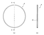
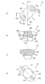
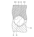
- FIG. 3 is a view taken in the direction of arrow A in FIGS. 1 and 2. It is a figure which shows the one end part of the screw shaft which comprises the ball screw apparatus of 1st Embodiment, and the outer ring
- FIG. 5 is a view taken in the direction of arrow B in FIGS. 1 and 4.
- FIG. 10A is a front view showing a rotation stop part for joining two outer ring divided bodies of a rolling bearing constituting the ball screw device of the ninth embodiment, and FIG. It is the elements on larger scale of FIG.
- FIG. 4B is a view taken in the direction of arrow b in FIG. 4A, and a part thereof is a BB cross-section
- FIG. 3C is a cross-sectional view taken along the line CC in FIG.
- wheel of the rolling bearing is displayed by the cross section.
- FIG. 30 is a sectional view taken along the line CC of FIG. 29. It is a figure which shows the holding piece which the rolling bearing of FIG.
- FIG. 1 It is an expanded sectional view showing a rolling bearing which constitutes a ball screw device of an 18th embodiment. It is a figure which shows the lid
- FIG. 1 It is a partial cross section side view which shows the ball screw apparatus (ball screw apparatus which has a cooling mechanism) of 23rd Embodiment, Comprising: A part of outer ring
- the ball screw device has the above configurations (1) to (3).
- the following configurations (4) to (14) and (21) to (21) can have any of the configurations (28).
- (4) Preload is applied to the rolling bearing.
- the inner ring raceway grooves and the outer ring raceway grooves have a plurality of rows, and the plurality of inner ring raceway grooves and outer ring raceway grooves have a single arc shape or a gothic arc shape.
- the outer ring is composed of two divided bodies divided between the two rows of the outer ring raceway grooves, A preload is applied to the rolling bearing by a spacer disposed between the two divided bodies.
- the inner ring raceway groove and the outer ring raceway groove have two rows, and the rolling bearing is preloaded with an oversize ball system.
- the outer peripheral surface of the outer ring is spherical.
- the outer ring is composed of two divided bodies divided between the two rows of the outer ring raceway grooves, Grooves are formed on the axial end surfaces of the two divided bodies that are in contact with each other, and the two divided bodies are arranged in both the radial direction and the axial direction by the anti-rotation parts arranged in the spaces formed by these grooves. It is restrained.
- the outer ring includes a small-diameter portion and a large-diameter portion having different outer diameters, the large-diameter portion has an axial end surface that contacts an axial end surface of a housing to which the outer ring is attached, and the small-diameter portion is the housing An outer peripheral surface that is in contact with the inner peripheral surface of the large-diameter portion, and a relief groove is formed at a corner portion formed by the axial end surface of the large-diameter portion on the small-diameter portion side and the outer peripheral surface of the small-diameter portion.
- the outer diameter of the outer peripheral surface of the screw shaft is the same between the portion where the spiral groove is formed and the portion where the inner ring raceway groove is formed.
- the amount of retained austenite ⁇ RS [volume%] on the surface (surface layer portion) of the screw shaft is such that the portion where the spiral groove is formed and the inner ring raceway groove are formed. The following formula (1) is satisfied in the portion where
- the screw device has the configuration (22), and the rolling bearing has a structure that suppresses non-uniform deformation in the axial direction caused by the load.
- one of the three or more rows of tracks (the side far from the load application point) is used as a preload applying track, and the other plurality of rows (the side near the load application point) is used as a load bearing track. To do. As a result, the load acting on one row of the load bearing track of the rolling bearing is reduced, so that the life of the rolling bearing can be extended.
- the track closer to the point of application of the load is smaller than the track on the far side. If all the preload amounts are the same, the amount of deformation of the rolling bearing will be greater on the track closer to the load application point than on the track farther, but by making this difference, all the preload amounts will be the same. Compared with the above, the non-uniformity of the deformation amount in the axial direction of the rolling bearing is improved.
- a ball screw device used in an application in which a non-uniform load is applied to the rolling bearing in the axial direction and has the configuration (22), and the diameter of the second ball is a plurality of rows.
- the track closer to the load application point is larger than the other tracks.
- the load capacity of the raceway closer to the load application point is increased and the life is increased. Long life.
- the cross-sectional area of the outer ring at the groove bottom position of the outer ring raceway groove is the same as the cross-sectional area of the portion of the screw shaft where the inner ring raceway groove is formed at the groove bottom position of the inner ring raceway groove.
- ⁇ N is the life ratio of the spiral groove of the nut to the required life of the ball screw device, and ⁇ N > 1.
- the amount of residual austenite ⁇ RS on the surface of the spiral groove of the screw shaft, and the residual of the surface of the spiral groove of the nut is preferably in a relationship of “ ⁇ RS > ⁇ RN ”.
- the amount of residual austenite ⁇ RS on the surface of the spiral groove of the screw shaft, and the residual of the surface of the spiral groove of the nut are preferably in a relationship of “ ⁇ RS > ⁇ RN > ⁇ RB ”.
- the ball screw device having the configuration (13) and the ball screw device having the configuration (14) are useful for electric injection molding machines, electric servo press machines, electric actuators, servo cylinders, or electric jacks. is there.
- thread groove surface means “spiral groove surface”.
- Examples of the ball screw device used with a stroke coefficient f S of less than 4.8 include an electric injection molding machine, an electric servo press machine, a servo cylinder, and an electric jack. Ball screw devices having 14) are useful for these. A similar effect can be obtained in the case of a roller screw device using a roller instead of the first ball.
- the retained austenite amount ⁇ RS [volume%] on the surface of the screw groove of the screw shaft satisfies the following formula (1).
- ⁇ S is the life ratio of the spiral groove of the screw shaft to the required life of the ball screw device, and ⁇ S > 1.
- the amount of retained austenite ⁇ RN [volume%] on the thread groove surface of the nut satisfies the following formula (2).
- ⁇ N is the life ratio of the spiral groove of the nut to the required life of the ball screw device, and ⁇ N > 1.
- the present inventors conducted various element tests with different amounts of retained austenite ⁇ R on the surface of the raceway surface subjected to induction heat treatment. Using the strips, the surface-origin type peel life was experimentally investigated. Further, the surface-origination peeling life (conventional life) when using a conventional screw shaft material (SAE4150) was also examined by the same method. As a result, the following relational expression (11) between the amount of retained austenite ⁇ R [volume%] on the surface of each test piece made of high-frequency heat treated material and the ratio ⁇ of the life of each test piece to the conventional life: It was found that
- the portion that becomes the raceway surface moves in the axial direction along with the linear movement of the nut. That is, in the screw shaft, a portion that receives stress due to the passage of the load ball becomes a part in the axial direction.
- the stroke of the nut is sufficiently long, the number of repetitions of stress applied to the raceway surface by passing through the load ball is greater on the nut side than on the screw shaft side, so that the first rolling fatigue failure occurs on the nut raceway surface.
- the retained austenite amount ⁇ R on the thread groove surface of the nut is made larger than the retained austenite amount ⁇ R on the thread groove surface of the screw shaft.
- the stroke of the nut is short, the magnitude relation of the number of stress repetitions to the raceway surface accompanying the passage of the load ball is reversed, and the screw shaft side is more than the nut side. Become more. For this reason, in the ball screw endurance test under operating conditions with a short stroke, it was confirmed that the first rolling fatigue failure tends to occur on the screw shaft side.
- the contact surface pressure between the ball and the raceway surface is higher on the screw shaft side than on the nut side, which is the basis for supporting that the first damage occurrence location is biased toward the screw shaft side.
- the fatigue life of the raceway surface is inversely proportional to the ninth power of the contact surface pressure, and the stress Since it is inversely proportional to the number of repetitions, the life ratio ⁇ of the nut raceway surface to the screw shaft raceway surface can be expressed by the following equation (12).
- P S and P N represent contact surface pressures on the raceway surface of the screw shaft and the nut
- N S and N N are the number of stress repetitions on the raceway of the screw shaft and the nut when operated for one stroke. Represents.
- ⁇ of the raceway surface of the nut with respect to the raceway surface of the screw shaft in a ball screw device under actual use conditions a total of 20 types of balls for electric injection molding machines that are put into practical use P S and P N and N S and N N were determined from the axial load and stroke of the screw device. Further, ⁇ of each model number was calculated by substituting these values into the equation (12).
- the stroke coefficient f S is a value obtained by dividing the stroke (St) by the product of the effective number of turns ( ⁇ ), the number of circuits ( ⁇ ), and the lead (l) of the ball screw device, as shown in Expression (14). .
- Expression (11) is an expression obtained from an experiment related to the screw shaft. Therefore, the amount of retained austenite ⁇ RS [volume%] on the surface of the thread groove of the screw shaft deforms equation (11) with ⁇ in equation (11) as the life ratio ⁇ S of the screw shaft raceway surface to the ball screw device. Therefore, it is expressed by the following equation (15).
- one of the preferred forms of the ball screw device is that the amount of retained austenite ⁇ RS and ⁇ RN on the surface of each screw groove of the screw shaft and nut (the surface of the spiral groove) is expressed by Equation (1) and ( The material of the screw shaft and the nut is not limited as long as each of the formulas 2) is satisfied, and more preferably “ ⁇ RS > ⁇ RN ”.
- high-frequency heat treatment is mainly applied to the screw shaft, and among the materials suitable for high-frequency heat treatment, the amount of retained austenite ⁇ RS on the screw groove surface of the screw shaft is reduced.
- high carbon bearing steel is preferred as the screw shaft material.
- the nut is preferably carbonitrided using case-hardened steel as in the conventional case.
- the entire ball screw device can be made inexpensive.
- a well-known method can be employ
- the output of the induction heating coil is controlled in a state in which a device for avoiding overheating is applied.
- the ball first ball, rolling element
- the surface where the ball contacts the screw shaft and the raceway surface of the nut under load changes every moment. Therefore, the ball has the longest life because the number of times each part of the rolling surface of the ball receives a load is smaller than that of the raceway surface of the screw shaft and the nut.
- the retained austenite amount ⁇ RB on the surface of the ball is preferably smaller than that of the screw shaft or the nut. That is, the magnitude relationship of the retained austenite amount ⁇ R of the three parties including the ball is preferably “ ⁇ RS > ⁇ RN > ⁇ RB ”. Satisfying these three magnitude relationships can maximize the balance between function and productivity when any component is damaged. Conventional balls can be used. By using a conventional ball, that is, a material obtained by burning the bearing steel, etc., the increase in the cost of the ball screw device can be suppressed.
- Ball screws for high load applications such as injection molding machines are designed so that a large load is applied in a fixed direction.
- a small-diameter portion (a portion having an outer diameter smaller than the outer diameter of the portion where the spiral groove is formed) is provided at both axial ends of the screw shaft so that an angular ball bearing or the like is brought into contact in the axial direction. Is forming. That is, stepped processing by cutting or grinding is performed.
- This small diameter part becomes the bearing support part, but the bearing support part is usually designed with a tightening allowance so that the inner ring does not creep with the bearing support part.
- the end face is ground.
- a relief groove or an R-shaped corner is formed in the bearing support portion, and this corner becomes a structural weak portion. Therefore, in an application where a large axial load is applied, it is necessary to take measures to prevent the stress from concentrating on the corner and breaking.
- the bearing support part As a countermeasure against this, instead of making the bearing support part a small diameter part, it is formed in a flange shape with a larger outer diameter than the part where the spiral groove is formed, and the axial end face of the bearing is pressed against this flange surface. Has been done.
- the screw shaft bar when making the screw shaft, in order to reduce the outer diameter other than the portion to be flanged, the screw shaft bar is closer to the center in the axial direction than the portion to be flanged. Since the process of cutting and grinding the part (part forming the spiral groove) and the axial end part is performed, the processing cost is increased.
- the bearing support portion (axial end portion) of the screw shaft is made the same as the portion where the spiral groove is formed, and the retained austenite amount ⁇ RS on the surface of the screw shaft including the bearing support portion is expressed by the above formula (1 ), It is possible to avoid stress concentration on the bearing support portion without increasing the processing cost. Further, in the ball screw device of one aspect of the present invention, the amount of retained austenite ⁇ RS on the surface of the screw shaft is expressed by the following equation (1) in the portion where the spiral groove is formed and the portion where the inner ring raceway groove is formed. If it is satisfied, the durability of the ball screw device is improved.
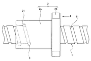
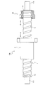
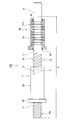
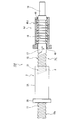
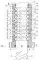
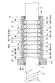
- the ball screw device 10 of the first embodiment includes a screw shaft 1 having a spiral groove 11 on the outer peripheral surface, a nut 2 having a spiral groove 21 on the inner peripheral surface, and a ball (first Ball) 3 with a ball screw. Both end portions of the screw shaft 1 are processed into a small-diameter portion 111 having a smaller diameter than the portion where the spiral groove is formed.
- the axial end portion (right end side in FIG.
- the nut 2 includes a cylindrical portion 2A and a flange portion 2B, and a bolt insertion hole 22 penetrating in the axial direction is formed in the flange portion 2B.
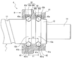
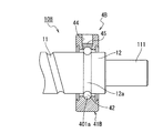
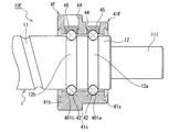
- the rolling bearing 4 includes two rows of inner ring raceway grooves 12a and 12b formed on the outer peripheral surface of one axial end portion 12 of the screw shaft 1, and an outer ring raceway facing the inner ring raceway grooves 12a and 12b.
- the outer ring 41 has grooves 401a and 401b and a plurality of balls (second balls) 42.
- the plurality of balls 42 are arranged so as to roll freely between the inner ring raceway grooves 12a and 12b and the outer ring raceway grooves 401a and 401b.
- the plurality of balls 42 are made of metal or ceramics.
- the rolling bearing 4 is a total ball bearing that does not have a cage.
- a synthetic resin or metal spacer ball or a synthetic resin holding piece may be disposed between the balls 42.
- the cross-sectional shapes of the inner ring raceway grooves 12a and 12b and the outer ring raceway grooves 401a and 401b are Gothic arc shapes.
- the rolling bearing 4 is preloaded with a DB (rear combination) structure by an offset preloading method. That is, L1> L2.
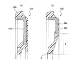
- the outer ring 41 includes a first raceway portion 41a in which an outer ring raceway groove 401a is formed and a second raceway portion 41b in which an outer ring raceway groove 401b is formed.
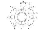
- a bolt insertion hole 43 penetrating in the axial direction is formed in an outer edge portion (a portion protruding outside the first track portion 41a) 41c of the second track portion 41b.
- Rolling element insertion holes 44 that penetrate from the outer peripheral surface to the outer ring raceway grooves 401a and 401b are formed in the first raceway portion 41a and the second raceway portion 41b, respectively.
- the two rolling element insertion holes 44 are each closed with a lid 45.
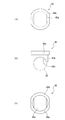
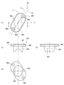
- the lid 45 includes a shaft portion 45a and a head portion 45b, and the tip surface (inner surface of the lid portion) 45c of the shaft portion 45a has a concave shape that forms part of the outer ring raceway grooves 401a and 401b. Is formed.
- the rolling element insertion hole 44 includes an inner portion 44a in which the shaft portion 45a is fitted and an outer portion 44b in which the head portion 45b is fitted. The lid 45 is fixed so that it does not float from the rolling element insertion hole 44 by using a C-shaped retaining ring or an adhesive after the ball 42 is inserted between the inner ring raceway grooves 12a, 12b and the outer ring raceway grooves 401a, 401b. Is done.
- the ball screw device 10 fixes a nut 2 to a member to be moved linearly, fixes an outer ring 41 of a rolling bearing 4 to a base via a housing, and drives a motor to a small diameter portion 111 of an axial end portion 12 of the screw shaft 1.
- the outer ring 41 is fixed to the housing by inserting the first raceway portion 41a into the housing, pressing the second raceway portion 41b against the axial end surface of the housing, and bolts passing through the bolt insertion holes 43 of the second raceway portion 41b. Is done.
- a deep groove ball bearing is attached to the small-diameter portion 111 of the other axial end portion 13, and the outer ring is fixed to the base via the housing.
- the rolling bearing 4 to which preload is applied is integrated with the ball screw. There is no need to adjust the preload when assembling to a machine. When the preload is applied at the customer, an error in assembly accuracy increases, and the rotation accuracy may decrease. On the other hand, according to the ball screw device 10 of the first embodiment, it is not necessary to make a preload adjustment when assembling to a machine tool or the like at the customer, and thus it is necessary to worry about a decrease in rotational accuracy due to the preload adjustment. Disappear.
- the rolling bearing 4 has high durability. Further, since the rolling element insertion hole 44 is formed in the outer ring 41, the ball 42 can be easily inserted from the outer peripheral surface side of the outer ring 41 between the inner ring raceway grooves 12a and 12b and the outer ring raceway grooves 401a and 401b. it can. Therefore, after the outer ring 41 is passed through the one axial end portion 12 of the screw shaft 1 and the outer ring raceway grooves 401a and 401b are opposed to the inner ring raceway grooves 12a and 12b, the ball 42 can be disposed between both raceway grooves.
- the axial load capacity and the radial load capacity of the rolling bearing 4 can be changed by changing the diameter of the ball 42 used without changing the inner ring raceway grooves 12a, 12b and the outer ring raceway grooves 401a, 401b.
- the front end surface 45c of the lid is formed in a concave shape forming a part of the outer ring raceway grooves 401a and 401b, the function as the rolling bearing 4 is not hindered.
- a preload having a DF (front combination) structure is applied to the rolling bearing 4A by an offset preload method. That is, L1 ⁇ L2 in FIG. The points other than this are the same as the ball screw device 10 of the first embodiment.
- a single row rolling bearing 4B is used, and a preload according to a request is applied in advance by, for example, an oversize ball system. The points other than this are the same as the ball screw device 10 of the first embodiment.
- the inner ring raceway groove 12a is provided in the portion where the spiral groove 11 is formed on the outer peripheral surface of the axial one end portion 12 without providing the small diameter portion 111.
- the points other than this are the same as the ball screw device 10 of the first embodiment.
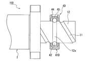
- the outer ring 41E of the rolling bearing 4E is composed of two divided bodies 411 and 412 divided between two rows of outer ring raceway grooves 401a and 401b.
- a spacer 413 is disposed between the two divided bodies 411 and 412.
- a preload is applied to the rolling bearing 4 ⁇ / b> E due to the force generated between the two divided bodies 411 and 412 by the spacer 413.
- the points other than this are the same as the ball screw device 10 of the first embodiment.
- the diameter of the ball 42 of the rolling bearing 4F is set so as to be opposed to the cross section perpendicular to the groove formed by the outer ring raceway grooves 401a and 401b and the inner ring raceway grooves 12a and 12b. It is larger than the distance between the arcs. As a result, the rolling bearing 4E is preloaded by the oversize ball method. The points other than this are the same as the ball screw device 10 of the first embodiment.
- the outer peripheral surface of the outer ring 41G of the rolling bearing 4G is spherical.
- the outer ring 41G has a centering property with respect to the housing.
- the points other than this are the same as the ball screw device 10 of the first embodiment.
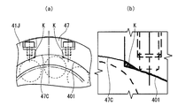
- the mounting error of the ball screw includes an inclination error shown in FIG. 14 (a) and a misalignment error shown in FIG. 14 (b). Moment load is generated by tilt error, and radial load is generated by misalignment error.
- the outer ring 41G has the alignment property, when the ball screw device 10 is used, it is possible to absorb the moment load and the radial load generated due to such a mounting error of the ball screw. Therefore, according to the ball screw device 10G of the eighth embodiment, in addition to the effects of the ball screw device 10 of the first embodiment, an effect of improving durability, torque characteristics, and feed accuracy can be obtained.
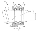
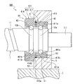
- the outer ring 41H of the rolling bearing 4H is composed of two divided bodies 411 and 412 divided between two rows of outer ring raceway grooves 401a and 401b. . Further, the outer ring 41H has a rotation stop component 6 that couples the two divided bodies 411 and 412 together.
- the first divided body 411 has an outer peripheral surface 411 a that fits into the inner peripheral surface 51 of the housing 5.
- the second divided body 412 includes a large diameter portion 414 having an outer diameter larger than that of the first divided body 411 and a small diameter portion 415 having the same outer diameter as that of the first divided body 411.
- the small diameter portion 415 has an outer peripheral surface 415 a that fits into the inner peripheral surface 51 of the housing 5.
- the anti-rotation component 6 is an annular member with a part cut, and has a circumferential groove 61 at the center in the width direction of the inner peripheral surface.
- the material of the anti-rotation component 6 include carbon steel, stainless steel, beryllium copper, and Inconel. Further, when fretting does not occur between the housing and the outer ring, a synthetic resin such as POM can be used.
- the first divided body 411 has a notch (groove) 411 c extending to the outer peripheral surface 411 a on the entire outer peripheral portion of the axial end surface 411 b in contact with the second divided body 412. Further, a convex portion 411d that protrudes radially outward is formed on the axial end surface 411b side of the notch portion 411c. Thereby, the groove 54 is formed by the inner peripheral surface 51 and the notch 411 c in a state where the first divided body 411 is fitted to the inner peripheral surface 51 of the housing 5.
- the second divided body 412 has a notch (groove) 412c extending to the outer peripheral surface 415a of the small diameter portion 415 over the entire outer peripheral portion of the axial end surface 412b that contacts the first divided body 411. Further, a convex portion 412d protruding outward in the radial direction is formed on the axial end surface 412b side of the notch portion 412c. As a result, the groove 55 is formed by the inner peripheral surface 51 and the notch portion 412 c in a state where the small diameter portion 415 of the second divided body 412 is fitted to the inner peripheral surface 51 of the housing 5.
- the second divided body 412 has relief grooves 416 at corners formed by the axial end surface 414 b on the small diameter portion 415 side of the large diameter portion 414 and the outer peripheral surface 415 a of the small diameter portion 415.
- the convex portion 411d of the first divided body 411 and the convex portion 412d of the second divided body 412 are formed to have the same dimensions, and the total value of these widths is slightly larger than the width of the circumferential groove 61 of the anti-rotation component 6.
- the axial end surfaces 411b and 412b of the first divided body 411 and the second divided body 412 are brought into contact with each other, the rotation stopper 6 is opened, and the circumferential groove 61 is fitted into the convex portions 411d and 412d.
- the two divided bodies 411 and 412 are restrained in both the radial direction and the axial direction by the stop component 6.
- a preload having a DF (front combination) structure is applied to the rolling bearing 4H by an offset preload method.
- the points other than the above are the same as the ball screw device 10 of the first embodiment.
- the ball screw device 10H As shown in FIG. 415 is fitted into the inner peripheral surface 51 of the housing 5 fixed to the base 7, and the axial end surface 411 e opposite to the axial end surface 411 b is pressed against the step surface 53 of the housing 5.
- the outer ring 41H is housed by a bolt through a bolt insertion hole provided in the outer edge of the second divided body 412 with the axial end face 412b of the second divided body 412 facing the axial end face 52 of the housing 5.
- Fix to 5 For example, a deep groove ball bearing is attached to the small diameter portion 111 of the other end portion 13 in the axial direction, and the outer ring is fixed to the base 7 via the housing.
- the two divided bodies 411 and 412 are restrained in both the radial direction and the axial direction by the anti-rotation component 6, so that the outer ring 41H is attached to the housing 5 in the attached state. There is no problem even if a gap is generated between the axial end surface 414b of the second divided body 412 and the axial end surface 52 of the housing 5.
- the outer peripheral surface 415 a of the small-diameter portion 415 of the second divided body 412 fits into the inner peripheral surface 51 of the housing 5, and the corner portion between the inner peripheral surface 51 and the axial end surface 52 of the housing 5 is the relief groove 416.
- the centering work of the outer ring 41H can be easily performed.
- the total width of the convex portion 411d of the first divided body 411 and the width of the convex portion 412d of the second divided body 412 is the width of the circumferential groove 61 of the anti-rotation component 6.
- the bolts are firmly tightened when the outer ring 41 ⁇ / b> H is fixed to the housing 5 with the above-described bolts. 5, the axial end surface 414 b of the second divided body 412 can be brought into close contact with the axial end surface 52 of the housing 5.
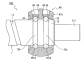
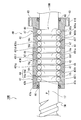
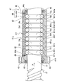
- the ball screw device 10Q of the tenth embodiment includes a ball screw including a screw shaft 1Q, a nut 2, and a ball (first ball) 3, and an outer ring 41Q of a rolling bearing 4Q.
- the screw shaft 1Q includes a spiral groove forming portion 15 in which a spiral groove 11 is formed on an outer peripheral surface, a race groove forming portion 16 in which an inner ring raceway groove of the rolling bearing 4 is formed, and a screw-up portion 17 therebetween.
- the raceway groove forming portion 16 is covered with an outer ring 41Q.
- the motor connection end portion 18 is an axial end portion that is continuous on the opposite side of the raceway groove forming portion 16 from the screw-up portion 17.
- the diameter of the circle forming the outer peripheral surface is the same in all of the spiral groove forming portion 15, the raceway groove forming portion 16, the screw-up portion 17, and the motor connection end portion 18. That is, the outer diameter of the outer peripheral surface of the screw shaft 1Q is the same in the entire axial direction except for the chamfered portion. No stepping is applied to both ends of the screw shaft 1Q.
- the screw shaft 1Q does not have the small diameter portion 111 like the screw shaft 1 of FIG. Further, the screw shaft 1Q extends in the axial direction from the range indicated by A in FIG. In the range up to the boundary position, the amount of retained austenite ⁇ RS [volume%] on the surface is heat-treated so as to satisfy the following formula (1).
- the motor connection end 18 is subjected to induction hardening and tempering.
- ⁇ S is the life ratio of the spiral groove of the screw shaft to the required life of the ball screw device, and ⁇ S > 1.
- high carbon bearing steel is used as the material of the screw shaft 1Q, and the region A is subjected to induction heat treatment so that the amount of retained austenite on the surface ⁇ RS [volume%] is in the region A.
- the formula (1) is satisfied.
- the material of the nut 2 is case-hardened steel and is carbonitrided.
- the material of the ball 3 is bearing steel and is baked.
- Each retained austenite amount ⁇ R of the screw shaft 1, the nut 2, and the ball 3 satisfies “ ⁇ RS > ⁇ RN > ⁇ RB ”. As shown in FIG.
- the nut 2 includes a cylindrical portion 2A and a flange portion 2B, and a bolt insertion hole penetrating in the axial direction is formed in the flange portion 2B.
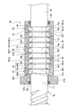
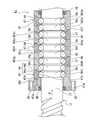
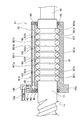
- the rolling bearing 4Q includes nine rows of inner ring raceway grooves 16a to 16i formed in the raceway groove forming portion 16 of the screw shaft 1Q and outer ring raceway grooves 401a to 401a facing the inner ring raceway grooves 16a to 16i.
- the outer ring 41Q having 401i, a plurality of balls (second balls) 42, and a pair of seals 46 are included.
- the plurality of balls 42 are arranged so as to roll freely between the opposed inner ring raceway grooves 16a to 16i and outer ring raceway grooves 401a to 401i.
- Each seal 46 is in contact with the screw-up portion 17 of the screw shaft 1 and the raceway groove forming portion 16 side near the motor connection end portion 18.
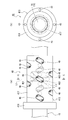
- the outer ring 41Q is composed of a cylindrical portion 417 and a flange portion 418. Outer ring raceway grooves 401 a to 401 i are formed in the cylindrical portion 417. A bolt insertion hole 43 that penetrates in the axial direction is formed in the flange portion 418. Further, rolling element insertion holes 44 penetrating from the outer peripheral surface to the outer ring raceway grooves 401a to 401i are formed in the cylindrical portion 417, respectively. The nine rolling element insertion holes 44 of the outer ring 41Q are formed at positions where the adjacent ones in the axial direction are shifted by 90 ° with respect to the cylindrical portion 417. Each rolling element insertion hole 44 is closed by a lid 47.
- the lid 47 includes a shaft portion 47a and a head portion 47b. Is formed. A bolt insertion hole 47d and a counterbore 47e are formed in the head 47b. A straight line Lc indicating the longitudinal direction of the ellipse forming the head 47b is inclined with respect to a straight line Lt perpendicular to the axial direction of the outer ring 41Q.
- a cross section AA in FIG. 21A can be seen in FIG.
- the rolling element insertion hole 44 of the outer ring 41 ⁇ / b> Q includes an inner portion 44 a in which the shaft portion 47 a of the lid 47 is fitted and an outer portion 44 b in which the head portion 47 b is fitted. Further, on the boundary surface 44c between the inner portion 44a and the outer portion 44b of the rolling element insertion hole 44, a female screw is formed at a position corresponding to each bolt insertion hole 47d of the lid 47.
- the lids 47 are placed in the respective rolling element insertion holes 44. Fit. After that, as shown in FIG. 20, bolts 49 are inserted into the bolt insertion holes 47 d and screwed into the female threads of the outer ring 41 ⁇ / b> Q, so that the lid 47 is fixed so as not to float from the rolling element insertion holes 44.
- the rolling bearing 4Q may be a total ball bearing without a cage, and a synthetic resin or metal spacer ball or a synthetic resin holding piece is disposed between the balls 42 and 42. May be.
- an offset preload system is used between the two raceways (each raceway formed by the outer ring raceway grooves 401a and 401B and the inner ring raceway grooves 16a and 16b) on the motor connection end 18 side of the rolling bearing 4Q.
- a preload of DB (backside combination) structure is applied. That is, the track closest to the motor connection end 18 (the track formed by the outer ring raceway groove 401a and the inner ring raceway groove 16a) is a track for applying preload, and other tracks (multiple rows of tracks for load bearing). Has the opposite contact angle.
- the ball screw device 10Q fixes the nut 2 to a member to be linearly moved, fixes the outer ring 41Q of the rolling bearing 4Q to the base via the housing, and connects the motor shaft end (one axial end) of the screw shaft 1Q. 18 is used by connecting a motor.
- the outer ring 41Q is fixed to the housing with a bolt that has a cylindrical portion 417 inside the housing, presses the flange portion 418 against the axial end surface of the housing, and passes through the bolt insertion hole 43 of the flange portion 418.
- a deep groove ball bearing is attached to the end portion 15a of the spiral groove forming portion 15, and the outer ring is fixed to the base via the housing.
- the rolling bearing 4Q to which the preload is applied is integrated with the ball screw. There is no need to adjust the preload when assembling to a machine. When the preload is applied at the customer, an error in assembly accuracy increases, and the rotation accuracy may decrease. On the other hand, according to the ball screw device 10Q of the tenth embodiment, it is not necessary to make a preload adjustment when assembling to a machine tool or the like at the customer, and therefore it is necessary to worry about a decrease in rotational accuracy associated with the preload adjustment. Disappear.
- the rolling element insertion hole 44 is formed in the outer ring 41Q, the ball 42 is easily inserted between the inner ring raceway grooves 16a to 16i and the outer ring raceway grooves 401a to 401i from the outer peripheral surface side of the outer ring 41Q. it can. Therefore, after the outer ring 41Q is passed through the one axial end portion 12 of the screw shaft 1Q and the outer ring raceway grooves 401a to 401i are opposed to the inner ring raceway grooves 16a to 16i, the ball 42 can be disposed between both raceway grooves.
- the ball screw device 10Q of the tenth embodiment includes the rolling bearing 4Q having nine rows of raceways, but the nine rows of inner ring raceway grooves 16a to 16i are formed in the screw shaft 1Q, and the nine rows of outer ring raceway grooves 401a to 401a. 401i is formed in one outer ring 41Q.
- the nine rows of rolling element insertion holes 44 are evenly arranged in the circumferential direction of the outer ring 41Q, the deformation of the outer ring 41Q in the plane perpendicular to the axis when an axial load is applied is made uniform. Can do. Thereby, the life of the outer ring 41Q is extended.
- the number of raceways of the rolling bearing is set to three rows or more, and among the raceways of three rows or more, It is preferable to reduce the load per row by using one row (the side far from the point of application of the load) as a preload application track and the other plurality of rows (side near the point of application of the load) as a load bearing track. .
- the outer diameter of the outer peripheral surface of the screw shaft 1Q is the same in the entire axial direction except for the chamfered portion, and the screw shaft 1Q is not stepped. Accordingly, stress concentration does not occur at the end 15a of the spiral groove forming portion 15 and the motor connection end portion 18, and therefore, the end of the spiral groove forming portion 15 is compared with the screw shaft that is stepped. Since the rigidity with respect to torsion and bending of the portion 15a and the motor connection end 18 is improved, the durability is improved.
- the outer diameter of the outer peripheral surface of the screw shaft 1Q is the same between the spiral groove forming portion 15 and the raceway groove forming portion 16, the outer diameter of the outer peripheral surface of the screw shaft 1Q is equal to the spiral groove forming portion 15 and the raceway groove forming portion. Compared with the case where the outer diameter is different from that of 16, the stress concentration is avoided, so that the durability is improved and the processing cost is reduced.
- the end portions are not deformed. Become good. Machining costs can be reduced by not performing stepped machining. Furthermore, in the ball screw device 10Q according to the tenth embodiment, the surface remains in the range A in the axial direction of the screw shaft 1Q, that is, in all of the spiral groove forming portion 15, the raceway groove forming portion 16, and the screw cut-up portion 17. Since the austenite amount ⁇ RS [volume%] satisfies the formula (1), the durability of both the ball screw portion and the bearing portion is increased.
- the ball screw device 10J of the eleventh embodiment includes a ball screw including a screw shaft 1J, a nut 2, and a ball (first ball) 3, and an outer ring 41J of a rolling bearing 4J.
- the screw shaft 1J includes a spiral groove forming portion 15 in which a spiral groove 11 is formed on an outer peripheral surface, a raceway groove forming portion 16 in which an inner ring raceway groove of the rolling bearing 4 is formed, and a screw-up portion 17 therebetween.
- the raceway groove forming portion 16 is covered with an outer ring 41J.
- the motor connection end portion 18 is an axial end portion that is continuous on the opposite side of the raceway groove forming portion 16 from the screw-up portion 17.
- the diameters of the circles forming the outer peripheral surface are the same.
- the diameter of the motor connection end portion 18 is smaller than the outer diameter of the raceway groove forming portion 16. That is, the motor connection end portion 18 is a small diameter portion.
- a spiral groove 21 is formed on the inner peripheral surface of the nut 2.
- the nut 2 includes a cylindrical portion 2A and a flange portion 2B, and a bolt insertion hole penetrating in the axial direction is formed in the flange portion 2B.
- the rolling bearing 4J includes nine rows of inner ring raceway grooves 16a to 16i formed in the raceway groove forming part 16 of the screw shaft 1J and outer ring raceway grooves 401a to 401a facing the inner ring raceway grooves 16a to 16i.
- the outer ring 41J having 401i, a plurality of balls (second balls) 42, and a pair of seals 46 are included.
- the plurality of balls 42 are arranged so as to roll freely between the opposed inner ring raceway grooves 16a to 16i and outer ring raceway grooves 401a to 401i.
- the plurality of balls 42 are made of metal or ceramics.
- Each seal 46 is in contact with the screw-up portion 17 of the screw shaft 1 and the raceway groove forming portion 16 side near the motor connection end portion 18.
- the outer ring 41J includes a cylindrical portion 417 and a flange portion 418. Outer ring raceway grooves 401 a to 401 i are formed in the cylindrical portion 417. A bolt insertion hole 43 that penetrates in the axial direction is formed in the flange portion 418. Further, rolling element insertion holes 44 penetrating from the outer peripheral surface to the outer ring raceway grooves 401a to 401i are formed in the cylindrical portion 417, respectively. The nine rolling element insertion holes 44 of the outer ring 41J are formed at positions where the adjacent ones in the axial direction are shifted by 90 ° from the cylindrical portion 417. Each rolling element insertion hole 44 is closed by a lid 47.
- the lid 47 includes a shaft portion 47a and a head portion 47b. Is formed. A bolt insertion hole 47d and a counterbore 47e are formed in the head 47b. A straight line Lc indicating the longitudinal direction of the ellipse forming the head 47b is inclined with respect to a straight line Lt perpendicular to the axial direction of the outer ring 41J.
- the AA cross section of FIG. 21A can be seen in FIG.
- the rolling element insertion hole 44 of the outer ring 41J includes an inner portion 44a in which the shaft portion 47a of the lid 47 is fitted, and an outer portion 44b in which the head portion 47b is fitted. Further, on the boundary surface 44c between the inner portion 44a and the outer portion 44b of the rolling element insertion hole 44, a female screw is formed at a position corresponding to each bolt insertion hole 47d.
- the lids 47 are placed in the respective rolling element insertion holes 44. Fit. Thereafter, as shown in FIG. 24, the bolts 49 are inserted into the bolt insertion holes 47d and screwed into the female threads of the outer ring 41J, so that the lid 47 is fixed so as not to float from the rolling element insertion holes 44.
- the rolling bearing 4J may be a total ball bearing that does not have a cage, and a synthetic resin or metal spacer ball or a synthetic resin holding piece is disposed between the balls 42 and 42. May be.
- the outer ring raceway groove has a large distance between adjacent groove bottoms. Between the other tracks, the distance between adjacent groove bottoms is the same in the inner ring raceway groove and the outer ring raceway groove.
- a preload having a DB (rear surface combination) structure is applied to the rolling bearing 4J by an offset preload method.
- the track closest to the motor connection end 18 (the track formed by the outer ring raceway groove 401a and the inner ring raceway groove 16a) is a track for applying preload, and other tracks (multiple rows of tracks for load bearing). Has the opposite contact angle.
- the nut 2 is fixed to the platen of the clamping unit of the electric injection molding machine, the outer ring 41J of the rolling bearing 4J is fixed to the base via the housing, and the motor connection end of the screw shaft 1J A motor is connected to (one axial end) 18 for use.
- the outer ring 41J is fixed to the housing by a bolt that has a cylindrical portion 417 inside the housing, presses the flange portion 418 against the axial end surface of the housing, and passes through the bolt insertion hole 43 of the flange portion 418.
- the rolling bearing 4J to which preload is applied is integrated with the ball screw. There is no need to adjust the preload when assembling to a machine. When the preload is applied at the customer, an error in assembly accuracy increases, and the rotation accuracy may decrease. On the other hand, according to the ball screw device 10J of the eleventh embodiment, it is not necessary to make a preload adjustment when assembling to a machine tool or the like at the customer, and thus it is necessary to worry about a decrease in rotational accuracy associated with the preload adjustment. Disappear.
- the rolling element insertion hole 44 is formed in the outer ring 41J, the ball 42 can be easily inserted between the inner ring raceway grooves 16a to 16i and the outer ring raceway grooves 401a to 401i from the outer peripheral surface side of the outer ring 41J. it can. Therefore, after the outer ring 41J is passed through the one axial end portion 12 of the screw shaft 1J and the outer ring raceway grooves 401a to 401i are opposed to the inner ring raceway grooves 16a to 16i, the ball 42 can be disposed between both raceway grooves.
- the ball screw device 10J of the eleventh embodiment has the rolling bearing 4J having nine rows of raceways, but the nine rows of inner ring raceway grooves 16a to 16i are formed on the screw shaft 1J, and the nine rows of outer ring raceway grooves 401a to 401a. 401i is formed in one outer ring 41J.
- the number of parts has decreased.
- the surface of a part is not necessarily uniform, and micro deformation occurs due to contact. Therefore, according to the ball screw device 10J, the deformation is reduced and the rigidity is improved as much as the contact between the parts is reduced.
- the outer diameter of the outer peripheral surface of the screw shaft 1J is the same between the spiral groove forming portion 15 and the raceway groove forming portion 16, the outer diameter of the outer peripheral surface of the screw shaft 1J is set to be the spiral groove forming portion 15 and the raceway groove forming portion. Compared with the case where the outer diameter is different from that of 16, the stress concentration is avoided, so that the durability is improved and the processing cost is reduced.
- a large load in the direction indicated by the arrow P in FIGS. 22 and 23 is applied to the raceway groove forming portion 16 of the screw shaft 1 when the ball screw device 10J is used. Therefore, a non-uniform load in the axial direction (a larger load than the side far from the nut 2 in the axial direction) is applied to the rolling bearing 4J.
- the rolling bearing 4J has nine rows of raceways and bears the load in eight rows other than the preload imparting raceway closest to the motor connection end 18 side, so the load per row becomes small. Thereby, it is possible to prevent the ball 42 existing on the flange 418 side track to which the largest load of the rolling bearing 4J is applied from being damaged early. Further, since the nine rows of rolling element insertion holes 44 are evenly arranged in the circumferential direction of the outer ring 41J, the deformation of the outer ring 41J in the plane perpendicular to the axis when an axial load is applied is made uniform. Can do. Thereby, the life of the outer ring 41J is extended. From the above, according to the ball screw device 10J of this embodiment, the life of the rolling bearing 4J can be extended when it is used for applications in which a non-uniform load is applied to the rolling bearing 4J in the axial direction. .
- FIG. 25 shows a rolling bearing 4K constituting the ball screw device 10K of the twelfth embodiment.
- the ball screw device 10K of the twelfth embodiment has an outer ring 41K that is different from the outer ring 41J of the ball screw device 10J of the eleventh embodiment.
- the screw shaft 1K of the ball screw device 10K has a raceway groove forming portion 16K different from the screw shaft 1J of the ball screw device 10J. Except for these points, the ball screw device 10K of the twelfth embodiment is the same as the ball screw device 10J of the eleventh embodiment.
- the rolling bearing 4K has nine rows of raceways, and the inner ring raceway grooves 16a to 16i and the outer ring raceway grooves 401a to 401i forming each raceway have a Gothic arc shape.
- the nine rows of rolling bearings 4K two raceways (outer ring raceway grooves 401a and 401b and inner ring raceway grooves 16a and 16b) at positions farthest from the flange portion 418 (on the motor connecting end 18 side shown in FIG. 22)
- the distance L11 between the groove bottoms of the outer ring raceway grooves 401a and 401b is greater than the distance L21 between the groove bottoms of the inner ring raceway grooves 16a and 16b.
- the distance L12 between the groove bottoms of the outer ring raceway grooves 401b and 401c is the same as the distance L22 between the groove bottoms of the inner ring raceway grooves 16b and 16c.
- the groove bottom distance L13 of the outer ring raceway grooves 401c and 401d is the same as the groove bottom distance L23 of the inner ring raceway grooves 16c and 16d.
- the distance L14 between the groove bottoms of the outer ring raceway grooves 401d and 401e is the same as the distance L24 between the groove bottoms of the inner ring raceway grooves 16d and 16e.
- the distance L15 between the groove bottoms of the outer ring raceway grooves 401e and 401f is the same as the distance L25 between the groove bottoms of the inner ring raceway grooves 16e and 16f.
- the groove bottom distance L16 of the outer ring raceway grooves 401f and 401g is the same as the groove bottom distance L26 of the inner ring raceway grooves 16f and 16g.
- the groove bottom distance L17 of the outer ring raceway grooves 401g and 401h is the same as the groove bottom distance L27 of the inner ring raceway grooves 16g and 16h.
- the distance L14 between the groove bottoms of the outer ring raceway grooves 401d and 401e is the same as the distance L24 between the groove bottoms of the inner ring raceway grooves 16d and 16e.
- the distance L18 is smaller than the distance L28 between the groove bottoms of the inner ring raceway grooves 16h and 16i.
- the rolling bearing 4K is the same as the rolling bearing 4J constituting the ball screw device 10J of the eleventh embodiment except for the points described above. Similarly to the ball screw device 10J of the eleventh embodiment, this ball screw device 10K also fixes, for example, the nut 2 to the platen of the mold clamping unit of the electric injection molding machine, and the outer ring 41K of the rolling bearing 4K through the housing. It is fixed to the base and used by connecting a motor to the motor connection end (one axial end) 18 of the screw shaft 1K.
- the outer ring 41K is fixed to the housing with a bolt that has a cylindrical portion 417 inside the housing, presses the flange portion 418 against the axial end surface of the housing, and passes through the bolt insertion hole 43 of the flange portion 418.
- the amount of preload is smaller than the other eight tracks on the track closest to the flange portion 418 among the nine rows of tracks.
- the amount of deformation in the axial direction is made uniform.
- the ball screw device 10K of the twelfth embodiment has the same configuration as the ball screw device 10J of the eleventh embodiment, so that the same effect as that obtained by the configuration of the ball screw device 10J can be obtained. Play.
- FIG. 26 shows a rolling bearing 4L constituting the ball screw device 10L of the thirteenth embodiment.
- the ball screw device 10L of the thirteenth embodiment is the same as the ball screw device 10J of the eleventh embodiment except for the portion of the rolling bearing 4L.
- the rolling bearing 4L constituting the ball screw device 10L of the thirteenth embodiment is the same as the rolling bearing 4J constituting the ball screw device 10J of the eleventh embodiment, except for the following points.
- the rolling bearing 4L As shown in FIG. 26, in the rolling bearing 4L, as in the rolling bearing 4J, nine rows of inner ring raceways 16a to 16i are formed in the raceway groove forming portion 16L of the screw shaft 1L, and nine rows of outer ring raceways are formed in the outer ring 41K. Grooves 401a to 401i are formed. In the rolling bearing 4J, all the raceway grooves have the same shape and the same dimensions, and balls 42 having the same dimensions are arranged. On the other hand, in the rolling bearing 4L, the track groove dimension is different between the track closest to the flange portion 418 (the track formed by the inner ring track groove 16i and the outer ring track groove 401i) and the other track.
- the track groove is formed larger in the track closest to the flange portion 418 than in the other tracks. That is, the width (axial dimension) and depth of the inner ring raceway groove 16i are larger than the widths and depths of the inner ring raceway grooves 16a to 16h. The width (axial dimension) and depth of the outer ring raceway groove 401i are larger than the width and depth of the outer ring raceway grooves 401a to 401h.
- the diameter of the ball 42a disposed on the track closest to the flange portion 418 is larger than the diameter of the ball 42 disposed on the other track.
- the tip end surface 47c of the lid 47a that closes the rolling element insertion hole 44 formed on the track closest to the flange portion 418 has a concave shape that forms a part of the outer ring raceway groove 401i having a larger size than the other, and the other lid 47 It is formed with a different dimension.
- the size of the track closest to the flange portion 418 is made larger than the others, and the diameter of the ball 42a is made larger than the balls 42 of other tracks. Therefore, the load capacity of the track that receives the largest load is larger than that of the other tracks. In other words, since measures are taken to increase the life of the track that receives the largest load, the life of the ball 42a rolling bearing 4L as a whole is extended.
- the ball screw device 10L of the thirteenth embodiment has the same configuration as the ball screw device 10J of the eleventh embodiment, so that the same effect as that obtained by the configuration of the ball screw device 10J can be obtained. Play.
- FIG. 27 shows a rolling bearing 4M constituting the ball screw device 10M of the fourteenth embodiment.
- the ball screw device 10M of the fourteenth embodiment is the same as the ball screw device 10J of the eleventh embodiment except for the portion of the rolling bearing 4M.
- the rolling bearing 4M constituting the ball screw device 10M of the fourteenth embodiment is the same as the rolling bearing 4J constituting the ball screw device 10J of the eleventh embodiment, except for the following points.
- the flange portion 418 is provided at a position closest to the nut 2.
- the flange portion 418 is provided at a position farthest from the nut 2.
- the flange portion 418 of the outer ring 41M of the rolling bearing 4M is provided at the position farthest from the nut 2, so that the flange portion 418 is positioned closest to the nut 2.
- the non-uniformity of the deformation amount in the axial direction of the rolling bearing is improved.
- the ball screw device 10M according to the fourteenth embodiment has the same configuration as the ball screw device 10J according to the eleventh embodiment, in addition to the above-described effects, and thus the same effect as that obtained by the configuration of the ball screw device 10J. Play.
- the rolling element insertion holes 44 are provided in addition to the axial ends of the cylindrical portion of the outer ring (the portion where the outer ring raceway groove is formed) 417. Since there is no non-existing portion, the flange portion 418 is provided at the axial end of the cylindrical portion 417 of the outer ring. However, the arrangement of the rolling element insertion hole 44 is changed so that the rolling element insertion hole 44 does not exist in a portion other than both axial ends of the cylindrical portion 417 of the outer ring (axial central portion), and a flange is provided at this portion. May be.
- the outer ring raceway groove also exists on the inner peripheral surface of the portion where the flange of the outer ring is formed. Even when the flange is arranged in the center portion in the axial direction of the outer ring, the rolling bearing is compared with the ball screw device 10J of the eleventh embodiment in which the flange portion 418 is provided at a position closest to the nut 2. The non-uniformity of the deformation amount in the axial direction is improved.
- the preload is applied by the offset preload method. That is, it has one row of tracks for applying preload and eight rows of other tracks. However, there may be a plurality of tracks for applying the preload, and in that case, the other tracks are provided more than the number of tracks for applying the preload.
- the preload may be applied by a method other than the offset preload.
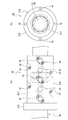
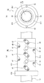
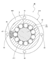
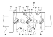
- FIG. 28 shows a cross section (cross section at the track groove bottom position) perpendicular to the axial direction of the rolling bearing 4N constituting the ball screw device.
- FIG. 29 shows a rolling bearing 4M constituting the ball screw device 10R of the sixteenth embodiment.
- the ball screw device 10R according to the sixteenth embodiment is the same as the ball screw device 10J according to the eleventh embodiment except for the portion of the rolling bearing 4R.
- the rolling bearing 4R constituting the ball screw device 10R of the fourteenth embodiment is the same as the rolling bearing 4J constituting the ball screw device 10J of the eleventh embodiment, except for the following points.
- FIG. 30 which is a CC cross-sectional view of FIG. 29, in the rolling bearing 4R, the holding piece 8 is disposed between the balls 42.
- the holding piece 8 is formed by forming spherical concave portions 81 corresponding to the spherical surfaces of the balls 42 on both bottom surfaces of the cylindrical body.
- the holding pieces 8 are arranged, it is possible to prevent the steel balls 42 from competing with each other, so that the durability of the balls 42 is improved. Moreover, when a crown type cage is used, it is necessary to secure a thickness for maintaining the ring shape. That is, by using the holding piece 8, the difference between the inner diameter of the outer ring and the outer diameter of the inner ring can be made smaller than when a crown type cage is used. As a result, since the raceway groove can be processed deeper, the contact angle can be made as large as possible, so that durability against an axial load is improved.
- the rolling bearing 4R of this embodiment has the lid
- the straight line Lc indicating the longitudinal direction of the ellipse forming the head 47b of the lid 47 is inclined with respect to the straight line Lt perpendicular to the axial direction of the outer ring 41R. Further, the centers of the two bolt insertion holes 47d exist on the straight line Lc.
- the land portion of the outer ring 41R (the portion between adjacent outer ring raceway grooves 401) 402
- the bolt 49 is screwed into the female screw hole formed in the above.
- the lid 47 is fixed to the rolling element insertion hole 44 of the outer ring 41R.
- the female screw hole is formed in the land portion 402 that is thicker than the portion where the outer ring raceway groove 401 is formed, so that the axial dimension (depth) of the female screw for attaching the lid 47 is increased. Can be secured, and the outer diameter of the bearing can be reduced.
- FIG. 32 shows a rolling bearing 4S constituting the ball screw device 10S of the seventeenth embodiment.
- the ball screw device 10S of the seventeenth embodiment is the same as the ball screw device 10J of the eleventh embodiment except for the portion of the rolling bearing 4R.
- the rolling bearing 4S constituting the ball screw device 10S of the seventeenth embodiment is the same as the rolling bearing 4J constituting the ball screw device 10J of the eleventh embodiment except for the following points.
- the rolling bearing 4S of this embodiment has a lid 48 shown in FIG. 33 instead of the lid 47 shown in FIG. As shown in FIG. 33, the lid 48 includes a shaft portion 48a and a head portion 48b.
- the planar shape of the shaft portion 48a is a long hole shape, and the tip surface (inner surface of the lid portion) 48c of the shaft portion 48a is formed in a concave shape that forms part of the outer ring raceway grooves 401a to 401i.
- the planar shape of the head 48b is a long hole, and a bolt insertion hole 48d and a counterbore 48e are formed in the head 48b.
- a straight line Lc indicating the longitudinal direction of the ellipse forming the head 48b is inclined with respect to a straight line Lt perpendicular to the axial direction of the outer ring 41S.
- the centers of the two bolt insertion holes 48d are not on the straight line Lc but on the straight line Ld whose inclination with respect to the straight line Lt is larger than the straight line Lc.
- the AA cross section of FIG. 33A is visible in FIG.
- the rolling element insertion hole 44 of the outer ring 41 ⁇ / b> S includes an inner portion 44 a in which the shaft portion 48 a of the lid 48 is fitted and an outer portion 44 b in which the head portion 48 b is fitted. Further, on the boundary surface 44c between the inner portion 44a and the outer portion 44b of the rolling element insertion hole 44, a female screw is formed at a position corresponding to each bolt insertion hole 48d. After fitting the lid 47 into the rolling element insertion hole 44 of the outer ring 41S, as shown in FIG. 49 is screwed. Accordingly, the lid 47 is fixed to the rolling element insertion hole 44 of the outer ring 41S.
- the female screw hole is formed in the land portion 402 that is thicker than the portion in which the outer ring raceway groove 401 is formed, so that the axial dimension (depth) of the female screw for attaching the lid 48 is increased. Can be secured, and the outer diameter of the bearing can be reduced.
- the planar shape of the axial part 48a is a long hole shape
- the inner side part 44a of the rolling element insertion hole 44 is also a long hole shape.
- the inner portion 44a of the rolling element insertion hole is circular, the inserted shaft portion 48a may rotate and interfere with the ball 42 and the cage, and the operability of the rolling bearing 4S may be deteriorated. If the inner portion 44a of the rolling element insertion hole 44 has a long hole shape, this possibility is lost. Therefore, the operability of the rolling bearing 4S is improved by using the lid 48 in which the planar shape of the shaft portion 48a is a long hole shape.
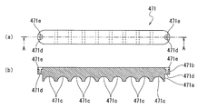
- FIG. 35 shows a rolling bearing 4T constituting the ball screw device of the eighteenth embodiment.
- the ball screw device of the eighteenth embodiment is the same as the ball screw device 10J of the eleventh embodiment except for the portion of the rolling bearing 4T.
- the rolling bearing 4T constituting the ball screw device of the eighteenth embodiment is the same as the rolling bearing 4J constituting the ball screw device 10J of the eleventh embodiment, except for the following points.
- the rolling bearing 4T of this embodiment has a lid 471 shown in FIG. 36 instead of the lid 47 shown in FIG. As shown in FIG.
- the outer ring 41T has one rolling element insertion hole 44 formed over all the outer ring raceway grooves 401a to 401i, and the rolling element insertion hole 44 is closed by one lid 471.
- the lid 471 includes a shaft portion 471a and a head portion 471b, and nine rows forming a part of each outer ring raceway groove 401a to 401i on the tip surface (inner surface of the lid portion) of the shaft portion 471a.
- the concave portion 417c is formed.
- Bolt insertion holes 471d and counterbore portions 471e are formed at both longitudinal ends of the head portion 471b.
- the rolling element insertion hole 44 of the outer ring 41T includes an inner portion 44a in which the shaft portion 471a of the lid 471 is fitted, and an outer portion 441b in which the head portion 417b is fitted. Further, on the boundary surface 44c between the inner portion 44a and the outer portion 44b of the rolling element insertion hole 44, a female screw is formed at a position corresponding to each bolt insertion hole 471d of the lid 471.
- the rolling bearing 4T has nine rows of raceways. After inserting the balls 42 into all of these raceways through one rolling body insertion hole 44, the rolling bodies The rolling bearing 4T can be assembled by closing the insertion hole 44 with one lid 471. Therefore, the assembly efficiency of the rolling bearing is higher than that of the ball screw device of the eleventh embodiment in which the rolling element insertion holes are provided in each track and the respective rolling element insertion holes are closed with the lids.
- a rolling element insertion hole is provided for each of two or more rows of raceways, and the rolling element insertion hole is closed with a corresponding lid to increase work efficiency. be able to.
- This embodiment is a modification of the ball screw device 10J of the eleventh embodiment.
- the contact seals 46A and 46B are composed of a core metal 46a and a highly elastic molded body 46b such as rubber.
- the low friction type contact seal 46B optimizes the shape A of the portion of the seal lip that contacts the inner ring and optimizes the pressing force (lip reaction force) on the inner ring by setting the dimension B of the lip portion. It is.
- the axial length of the screw shaft can be shortened by using the low friction type contact seal 46B. Along with this, the rotational inertia moment of the screw shaft can be kept small, so that the load on the motor can be reduced.
- This embodiment is a modification of the ball screw device 10J of the eleventh embodiment.
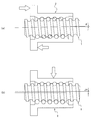
- the rolling bearing 4J constituting the ball screw device 10J uses the seal 46, but the rolling bearing 4U constituting the ball screw device of this embodiment employs an air seal structure shown in FIG. 38 instead.
- the air seal is a non-contact seal, and the seal torque (seal resistance) can be reduced as much as possible when a contact seal is used.
- a long through hole 419 extending in the axial direction of the outer ring 41U is provided, and air is allowed to flow from both the flange portion 418 and the end portion of the cylindrical portion 417 opposite to the flange portion 418 to the through hole 419. ing. Thereby, the inflow port of air can be decreased.
- This embodiment is a modification of the ball screw device 10J of the eleventh embodiment, and the ball 42 of the rolling bearing 4J constituting the ball screw device 10J is made of a material having a lower density than the bearing steel. . Specific examples include ceramics (silicon nitride, silicon carbide, alumina, etc.).
- a ball screw for high load applications such as an injection molding machine is designed so that a large load is applied in a predetermined direction. Therefore, the load capacity is increased by increasing the diameter of the ball 42.
- the ball 42 is inserted from the rolling element insertion hole 44 provided in the outer ring 41J, the rolling element insertion hole 44 is covered with a lid 47, and the lid 47 is fixed with a bolt 49. Therefore, a large centrifugal force acting on the ball 42 by high-speed rotation is intermittently applied to the bolt 49 of the lid 47, and the bolt 49 may not be able to withstand this centrifugal force.
- a method of increasing the proof strength of the bolt 49 by increasing the number of bolts 49 or the effective diameter of the bolts 49 can be considered. However, in this method, it is necessary to increase the number of parts or increase the outer diameter of the outer ring 41J.
- the ball 42 made of a material having a density lower than that of the bearing steel such as ceramics is used, the ball 42 becomes light, and thus the centrifugal force is reduced. As a result, the load applied to the bolt 49 that fixes the lid 47 can be reduced. Accordingly, the bolt 49 can withstand the centrifugal force of the ball 42 during high-speed rotation without increasing the effective diameter and number of the bolts 49 that fix the lid 47.
- This greasing path includes a through hole 140 extending along the axial direction of the outer ring 41J, and a greasing hole 141b, 141d, 141f, 141h extending vertically from the through hole 140 toward the outer ring raceway grooves 401b, 401d, 401f, 401h, And a through hole 142 formed in the flange portion 418 and extending in the radial direction.
- Both ends of the through hole 140 are closed with plugs 143.
- the opening part of the outer peripheral part produced in order to open the greasing hole 141b, 141d, 141f, 141h in the cylindrical part 417 is also plugged up with the plug 143.
- a joint 145 of a grease (or lubricating oil) pipe 144 is connected to an end portion on the outer peripheral side of the through hole 142 of the flange portion 418.
- the amount of grease (or lubricating oil) flowing into each greasing hole is equalized by increasing the cross-sectional area of the greasing hole as it is farther from the flange portion 418 on the upstream side of the greasing passage. . That is, the relationship of the cross-sectional area of the greasing hole satisfies the greasing hole 141h ⁇ the greasing hole 141f ⁇ the greasing hole 141d ⁇ the greasing hole 141b.
- each of the greasing holes 141b, 141d, 141f, 141h is formed in a size such that the ball 42 does not come into contact with the greasing hole at the center in the width direction of each outer ring raceway groove. Thereby, a good greasing effect is obtained.
- a structure in which a greasing path is provided on the screw shaft 1J can be mentioned.
- This greasing path has a center hole 146 extending in the axial direction of the screw shaft 1 and greasing holes 141a to 141i extending vertically from the center hole 146 to the inner ring raceway grooves 16a to 16i.
- the center hole 146 is formed in a range including the motor connection end portion 18, the raceway groove forming portion 16, and the screw cut-up portion 17. Both ends of the center hole 146 are closed with plugs 143.
- An annular member 147 is externally fitted to the boundary between the motor connection end 18 and the raceway groove forming portion 16. Holes 146a and 146b extending perpendicularly from the center hole 146 are formed in a portion where the annular member 147 of the motor connection end 18 is fitted.
- the recessed annular member 147 has inner circumferential grooves 147a and 147b communicating with the holes 146a and 146b.
- the annular member 147 has a hole 146c extending from the inner peripheral groove 147a to the outer peripheral end along the radial direction.
- a joint 145 of a grease (or lubricating oil) pipe 144 is connected to the outer peripheral end of the hole 146c.
- a hermetic seal 150 is disposed between the annular member 147, the raceway groove forming portion 16, and the motor connection end portion 18.
- the inner circumferential groove 147b becomes a lubricant reservoir.
- the arrow indicates the flow of grease (or lubricating oil).
- grease or lubricating oil
- FIG. 40 by providing the greasing holes 141a to 141i toward all the inner ring raceways 16a to 16i, a high greasing effect can be obtained.
- grease (or lubricating oil) can be effectively replenished by the rotation (centrifugal force) of the screw shaft.
- the amount of grease (or lubricating oil) flowing into each greasing hole can be equalized.
- the example shown in FIG. 41 is an example in which a grease supply path is provided in the outer ring 41J, similar to the example of FIG. 39, but is illustrated in that it has a plurality of grease supply paths in the circumferential direction of one outer ring raceway groove 401.
- a grease supply path is provided in the outer ring 41J, similar to the example of FIG. 39, but is illustrated in that it has a plurality of grease supply paths in the circumferential direction of one outer ring raceway groove 401.
- four greasing paths composed of the through holes 140 and the greasing holes 141 are provided at intervals of 90 °.
- the greasing effect can be enhanced by providing a plurality of greasing holes in one track.
- a further higher greasing effect can be obtained by equally arranging a plurality of greasing holes.
- a greasing hole 141 is provided in the lid 47.
- the greasing hole 141 is formed so as to extend along the radial direction of the outer ring 41J when the lid 47 is attached.
- the greasing hole 141 is closed with a plug 143.
- one greasing hole 141 is formed in one lid 47.
- a plurality of greasing holes can be provided in one lid 47 to enhance the greasing effect.
- a solid lubricant film may be attached to the inner peripheral surface of the lid 47.
- the lid 47 may be formed of a material containing a solid lubricant.
- a solid lubricant film may be attached to a portion of the ball holding component such as the cage or the holding piece 8 that comes into contact with the ball 42.
- ball holding components such as a holder
- a solid lubricant film may be attached to the surface 4011 of the outer ring 41J that contacts the ball 42 of the outer ring raceway groove and the surface 161 of the inner ring raceway groove forming portion 16 that contacts the ball 42 of the inner ring raceway groove. . If the solid lubricating film on the surfaces 4012 and 162 on the side not normally in contact with the ball 42 is thickened or the shape is devised so as to come into contact with the ball 42, the lubricating effect can be further enhanced. Also, as shown in FIG.
- the crown 42 is crowned at a portion (corner portion between the rolling element insertion hole 44 and the outer ring raceway groove 401) that contacts when the ball 42 moves from the outer ring raceway groove 401 to the tip surface 47c of the lid 47.
- (Inclined portion) K may be provided, and grease may be accumulated in the portion.
- the ball screw device 10V of this embodiment has a cooling mechanism. Other points are the same as the ball screw device 10J of the eleventh embodiment.
- a through hole 1001 extending in the axial direction is formed in the axial center of the screw shaft 1V.
- a coolant supply pipe 1002 is connected to one end of the through hole 1001, and a coolant discharge pipe 1003 is connected to the other end. Thereby, the coolant supplied to the coolant supply pipe 1002 passes through the through hole 1001 arranged in the entire axial direction of the screw shaft 1V and is then discharged to the outside from the coolant discharge pipe 1003. The screw shaft 1V is cooled by this coolant.
- Through holes 1201 extending in the axial direction are formed at four locations (a plurality of locations) in the circumferential direction of the nut 2V.
- the coolant supply pipe 1202 is connected to one through hole 1201 and the coolant discharge pipe 1203 is connected to the adjacent through hole 1201 at the axial end opposite to the flange part 2B of the cylindrical part 2A.
- the other two through holes 1201 are connected by a pipe 1204.
- the other end of the through hole 1201 whose one end is connected to the coolant supply pipe 1202 is connected by the adjacent through hole 1201 and the pipe 1205, and one end is connected to the coolant discharge pipe 1203.
- the other end of the connected through hole 1201 is connected to the adjacent through hole 1201 by a pipe 1206.
- the coolant supplied to the coolant supply pipe 1202 is discharged to the outside from the coolant discharge pipe 1203 after passing through all the through holes 1201 of the nut 2V.
- the nut 2V is cooled by this coolant.
- Through holes 1401 extending in the axial direction are formed at four locations (a plurality of locations) in the circumferential direction of the outer ring 41V of the rolling bearing 4V.
- a coolant supply pipe 1402 is connected to one through hole 1401 and a coolant discharge pipe 1403 is connected to the adjacent through hole 1401 at the end in the axial direction opposite to the flange part 418 of the cylindrical part 417.
- the other two through holes 1401 are connected by a pipe 1404.
- the other end of the through hole 1401 whose one end is connected to the coolant supply pipe 1402 is connected by the adjacent through hole 1401 and the pipe 1405, and one end is connected to the coolant discharge pipe 1403.
- the other end of the connected through hole 1401 is connected to the adjacent through hole 1401 by a pipe 1406.
- the coolant supplied to the coolant supply pipe 1402 is discharged to the outside from the coolant discharge pipe 1203 after passing through all the through holes 1401 of the outer ring 41V.
- the outer ring 41V is cooled by this coolant.
- the coolant is allowed to flow along the axial direction in any of the screw shaft 1V, the nut 2V, and the outer ring 4V.
- the coolant flows through a plurality of through holes provided in series.
- a turbulent flow Reynolds number 2000 or more
- the ball screw device 10V cools not only the nut 2V and the outer ring 4V but also the screw shaft 1 including the raceway groove forming portion 16 in which the inner raceway groove is formed. .
- a plurality of through-holes 1401 are connected by pipes 1205 and 1206 at the end on the flange portion 418 side. You may go.
- connection member 1500 has a cooling water passage 1501 along the circumferential direction and a connection port 1402 that overlaps the plurality of through holes 1401.
- a small-diameter portion 4180 is formed at the end in the axial direction of the outer ring 41V on the flange portion 418 side, and the connection member 1500 has a coupling portion 1503 that is externally fitted to the small-diameter portion 4180.
- a seal 1600 is attached between the small diameter portion 4180 and the connection member 1500.
- the example in FIG. 46 is smaller than the example in FIG. 45 by using the connection member 1500 instead of the pipes 1205 and 1206, and the risk of liquid leakage is reduced by having fewer joints. In many cases, the connection using the connection member 1500 as shown in FIG. 46 is actually employed in a ball screw cooling mechanism.
- Screw shaft 11 Spiral groove of screw shaft 12 One axial end portion of screw shaft 12a, 12b Inner ring raceway groove 15 Spiral groove forming portion (spiral groove is formed portion) 16, 16K to 16N raceway groove forming portion (the portion where the inner ring raceway groove is formed) 16a Inner ring raceway groove 16b Inner ring raceway groove 16c Inner ring raceway groove 16d Inner ring raceway groove 16f Inner ring raceway groove 16f Inner ring raceway groove 16h Inner ring raceway groove 16i Inner ring raceway groove 16n Inner ring raceway groove 17 Screw-up portion 2 Nut 21 Spiral groove of nut 3 Ball (first ball) 4, 4A to 4H, 4J to 4M, 4Q Rolling bearings 41, 41A to 41H, 41J to 41N, 41Q Outer ring 401a Outer ring raceway groove 401b Outer ring raceway groove 401c Outer ring raceway groove
Landscapes
- Engineering & Computer Science (AREA)
- General Engineering & Computer Science (AREA)
- Mechanical Engineering (AREA)
- Manufacturing & Machinery (AREA)
- Transmission Devices (AREA)
- Mounting Of Bearings Or Others (AREA)
- Rolling Contact Bearings (AREA)
Priority Applications (5)
| Application Number | Priority Date | Filing Date | Title |
|---|---|---|---|
| EP17869656.3A EP3540264B1 (en) | 2016-11-11 | 2017-11-10 | Ball screw device |
| US16/347,885 US20190353230A1 (en) | 2016-11-11 | 2017-11-10 | Ball Screw Device |
| JP2018550290A JP6669275B2 (ja) | 2016-11-11 | 2017-11-10 | ボールねじ装置 |
| KR1020197014602A KR102466323B1 (ko) | 2016-11-11 | 2017-11-10 | 볼 나사 장치 |
| CN201780068424.3A CN109923333B (zh) | 2016-11-11 | 2017-11-10 | 滚珠丝杠装置 |
Applications Claiming Priority (6)
| Application Number | Priority Date | Filing Date | Title |
|---|---|---|---|
| JP2016220442 | 2016-11-11 | ||
| JP2016-220442 | 2016-11-11 | ||
| JP2017202936 | 2017-10-19 | ||
| JP2017-202936 | 2017-10-19 | ||
| JP2017202935 | 2017-10-19 | ||
| JP2017-202935 | 2017-10-19 |
Publications (1)
| Publication Number | Publication Date |
|---|---|
| WO2018088540A1 true WO2018088540A1 (ja) | 2018-05-17 |
Family
ID=62110694
Family Applications (1)
| Application Number | Title | Priority Date | Filing Date |
|---|---|---|---|
| PCT/JP2017/040647 Ceased WO2018088540A1 (ja) | 2016-11-11 | 2017-11-10 | ボールねじ装置 |
Country Status (6)
| Country | Link |
|---|---|
| US (1) | US20190353230A1 (enExample) |
| EP (1) | EP3540264B1 (enExample) |
| JP (2) | JP6669275B2 (enExample) |
| KR (1) | KR102466323B1 (enExample) |
| CN (1) | CN109923333B (enExample) |
| WO (1) | WO2018088540A1 (enExample) |
Cited By (3)
| Publication number | Priority date | Publication date | Assignee | Title |
|---|---|---|---|---|
| JP2021076211A (ja) * | 2019-11-12 | 2021-05-20 | 日本精工株式会社 | ボールねじ |
| CN113983144A (zh) * | 2021-09-24 | 2022-01-28 | 北京航空航天大学 | 一种基于sma丝及螺旋摩擦副的空间轴系变预载机构 |
| US11975755B2 (en) * | 2020-10-13 | 2024-05-07 | Nsk Ltd. | Screw shaft and method for producing same, and electric position-adjusting device for steering wheel |
Families Citing this family (12)
| Publication number | Priority date | Publication date | Assignee | Title |
|---|---|---|---|---|
| US10583917B2 (en) * | 2017-05-18 | 2020-03-10 | Goodrich Corporation | Electromechanical actuator disconnect |
| EP3587864B1 (en) * | 2018-06-27 | 2021-05-05 | Goodrich Actuation Systems Limited | Ballnut lubrication |
| JP7166185B2 (ja) * | 2019-02-06 | 2022-11-07 | Thk株式会社 | 予圧検知可能なねじ装置 |
| DE102020109189A1 (de) * | 2020-04-02 | 2021-10-07 | Andreas Hettich Gmbh & Co. Kg | Einsatz für einen Rotor einer Zentrifuge |
| CN112032268B (zh) * | 2020-08-24 | 2023-11-24 | 江西沃德成科技有限公司 | 一种行星滚柱丝杠用滚柱及其制造方法 |
| JP7494711B2 (ja) * | 2020-11-27 | 2024-06-04 | 日本精工株式会社 | ボールねじ |
| JP7517229B2 (ja) * | 2021-03-31 | 2024-07-17 | 日本精工株式会社 | ボールねじ装置 |
| US11421763B1 (en) * | 2021-05-24 | 2022-08-23 | Rockford Ball Screw | Ball screw actuator for accommodating misalignment |
| CN113464572B (zh) * | 2021-06-29 | 2022-06-24 | 人本股份有限公司 | 快速连接的压板轴承装置 |
| CN114992298A (zh) * | 2022-07-12 | 2022-09-02 | 安顺虹特滚珠丝杠有限责任公司 | 一种连轴滚珠丝杠副及加工方法 |
| EP4306814A1 (en) | 2022-07-13 | 2024-01-17 | Goodrich Actuation Systems Limited | Radial bearing system for ball nut and screw assembly and corresponding manufacturing method |
| CN118775514B (zh) * | 2024-09-10 | 2024-12-13 | 万向钱潮股份公司 | 一种丝杠及丝杠制动方法 |
Citations (2)
| Publication number | Priority date | Publication date | Assignee | Title |
|---|---|---|---|---|
| JP2002174229A (ja) * | 2000-12-07 | 2002-06-21 | Koyo Seiko Co Ltd | 旋回座軸受 |
| JP2007285480A (ja) | 2006-04-19 | 2007-11-01 | Nsk Ltd | 回転軸支持装置およびその回転軸の製造方法 |
Family Cites Families (13)
| Publication number | Priority date | Publication date | Assignee | Title |
|---|---|---|---|---|
| GB616979A (en) * | 1946-01-18 | 1949-01-31 | Alfred Paul Mill | Worm and nut mechanism |
| US3762227A (en) * | 1971-10-12 | 1973-10-02 | Gen Motors Corp | Damped and cushioned stop |
| JPS58146753A (ja) * | 1982-02-26 | 1983-09-01 | Hiroshi Teramachi | ボ−ルねじ |
| JPH04228919A (ja) * | 1990-12-27 | 1992-08-18 | Fuji Car Mfg Co Ltd | 旋回座ベアリング |
| US7287910B2 (en) * | 2001-09-03 | 2007-10-30 | Ntn Corporation | Angular ball bearing and rolling bearing |
| TWI221512B (en) * | 2002-04-15 | 2004-10-01 | Smc Corp | Ball screw mechanism |
| US6851537B2 (en) * | 2003-03-07 | 2005-02-08 | Magna Drivetrain Of America, Inc. | Worm driven ball screw actuator for traction clutches |
| EP1515066B1 (en) * | 2003-09-10 | 2014-01-08 | Nsk Ltd | Ball screw apparatus |
| US20060107779A1 (en) * | 2004-11-24 | 2006-05-25 | Chien-Wei Tsou | Ball screw nut with ball bearing ring and fabrication method of same |
| USRE48336E1 (en) * | 2006-05-19 | 2020-12-01 | Nsk Ltd. | Rolling apparatus |
| JP5138616B2 (ja) * | 2009-01-20 | 2013-02-06 | Ntn株式会社 | ボールねじ軸の支持構造 |
| US20140321776A1 (en) * | 2012-01-19 | 2014-10-30 | Nsk Ltd. | Self-Lubricating Composite Material and Rolling Bearing, Linear Motion Device, Ball Screw Device, Linear Motion Guide Device, and Transport Device Using the Same |
| JP5818925B2 (ja) * | 2014-02-13 | 2015-11-18 | Thk株式会社 | ボールねじ装置 |
-
2017
- 2017-11-10 EP EP17869656.3A patent/EP3540264B1/en active Active
- 2017-11-10 US US16/347,885 patent/US20190353230A1/en not_active Abandoned
- 2017-11-10 JP JP2018550290A patent/JP6669275B2/ja active Active
- 2017-11-10 CN CN201780068424.3A patent/CN109923333B/zh active Active
- 2017-11-10 KR KR1020197014602A patent/KR102466323B1/ko active Active
- 2017-11-10 WO PCT/JP2017/040647 patent/WO2018088540A1/ja not_active Ceased
-
2020
- 2020-02-27 JP JP2020032272A patent/JP6962398B2/ja active Active
Patent Citations (2)
| Publication number | Priority date | Publication date | Assignee | Title |
|---|---|---|---|---|
| JP2002174229A (ja) * | 2000-12-07 | 2002-06-21 | Koyo Seiko Co Ltd | 旋回座軸受 |
| JP2007285480A (ja) | 2006-04-19 | 2007-11-01 | Nsk Ltd | 回転軸支持装置およびその回転軸の製造方法 |
Non-Patent Citations (1)
| Title |
|---|
| See also references of EP3540264A4 |
Cited By (4)
| Publication number | Priority date | Publication date | Assignee | Title |
|---|---|---|---|---|
| JP2021076211A (ja) * | 2019-11-12 | 2021-05-20 | 日本精工株式会社 | ボールねじ |
| US11975755B2 (en) * | 2020-10-13 | 2024-05-07 | Nsk Ltd. | Screw shaft and method for producing same, and electric position-adjusting device for steering wheel |
| CN113983144A (zh) * | 2021-09-24 | 2022-01-28 | 北京航空航天大学 | 一种基于sma丝及螺旋摩擦副的空间轴系变预载机构 |
| CN113983144B (zh) * | 2021-09-24 | 2023-08-08 | 北京航空航天大学 | 一种基于sma丝及螺旋摩擦副的空间轴系变预载机构 |
Also Published As
| Publication number | Publication date |
|---|---|
| CN109923333B (zh) | 2022-05-06 |
| JPWO2018088540A1 (ja) | 2019-06-24 |
| EP3540264A4 (en) | 2020-06-03 |
| KR20190077425A (ko) | 2019-07-03 |
| EP3540264B1 (en) | 2021-08-11 |
| EP3540264A1 (en) | 2019-09-18 |
| KR102466323B1 (ko) | 2022-11-10 |
| JP6669275B2 (ja) | 2020-03-18 |
| JP6962398B2 (ja) | 2021-11-05 |
| JP2020098034A (ja) | 2020-06-25 |
| US20190353230A1 (en) | 2019-11-21 |
| CN109923333A (zh) | 2019-06-21 |
Similar Documents
| Publication | Publication Date | Title |
|---|---|---|
| JP6962398B2 (ja) | ボールねじ装置 | |
| EP0095891B1 (en) | Devices for converting rotary movement into linear movement | |
| EP2187074B1 (en) | Method of manufacture of a rolling bearing | |
| US9506544B2 (en) | Seal member and linear motion guide device using same | |
| JP2008202672A (ja) | ボールねじ及びその製造方法 | |
| JP4743176B2 (ja) | 組合せ玉軸受及び複列玉軸受 | |
| JP2004270792A (ja) | 多点接触玉軸受 | |
| JP6122636B2 (ja) | 軌道レールに埋栓を備えた直動案内ユニット | |
| JP2016217916A (ja) | クロスローラベアリング及び該クロスローラベアリングの予圧量計測方法 | |
| EP1416177B1 (en) | Bearing | |
| US10197094B2 (en) | Double-row spherical roller bearing | |
| CN103438093A (zh) | 滚珠丝杠专用轴承高刚度支承牵拉机构 | |
| JP2003172341A (ja) | ボールねじ支持用多点接触玉軸受 | |
| EP4603715A1 (en) | Bearing device and spindle device with bearing device | |
| JP2002235755A (ja) | 転がり軸受 | |
| JP2005048847A (ja) | ボールねじ一体型直動案内ユニット | |
| JP3011666U (ja) | 直動案内軸受における潤滑材供給ニップルの取付構造 | |
| JP2003172342A (ja) | ボールねじ支持用多点接触玉軸受 | |
| JP2024064773A (ja) | ボールねじ | |
| WO2016138867A1 (zh) | 一种满滚动体轴连轴承及其制造方法 | |
| JP2000213537A (ja) | 直動案内ユニット | |
| JP2008064207A (ja) | ボールねじ装置 | |
| JP2007218356A (ja) | 直動装置用セパレータ及び直動装置 | |
| JP2003294029A (ja) | 減速機用多点接触玉軸受 | |
| JP2012092919A (ja) | 転がり軸受 |
Legal Events
| Date | Code | Title | Description |
|---|---|---|---|
| 121 | Ep: the epo has been informed by wipo that ep was designated in this application |
Ref document number: 17869656 Country of ref document: EP Kind code of ref document: A1 |
|
| ENP | Entry into the national phase |
Ref document number: 2018550290 Country of ref document: JP Kind code of ref document: A |
|
| NENP | Non-entry into the national phase |
Ref country code: DE |
|
| ENP | Entry into the national phase |
Ref document number: 20197014602 Country of ref document: KR Kind code of ref document: A |
|
| ENP | Entry into the national phase |
Ref document number: 2017869656 Country of ref document: EP Effective date: 20190611 |