EP3540264A1 - Ball screw device - Google Patents
Ball screw device Download PDFInfo
- Publication number
- EP3540264A1 EP3540264A1 EP17869656.3A EP17869656A EP3540264A1 EP 3540264 A1 EP3540264 A1 EP 3540264A1 EP 17869656 A EP17869656 A EP 17869656A EP 3540264 A1 EP3540264 A1 EP 3540264A1
- Authority
- EP
- European Patent Office
- Prior art keywords
- ball screw
- outer ring
- screw device
- threaded shaft
- ring raceway
- Prior art date
- Legal status (The legal status is an assumption and is not a legal conclusion. Google has not performed a legal analysis and makes no representation as to the accuracy of the status listed.)
- Granted
Links
- 238000005096 rolling process Methods 0.000 claims abstract description 283
- 238000003780 insertion Methods 0.000 claims abstract description 99
- 230000037431 insertion Effects 0.000 claims abstract description 99
- 230000033001 locomotion Effects 0.000 claims abstract description 7
- 230000000149 penetrating effect Effects 0.000 claims abstract description 6
- 229910001566 austenite Inorganic materials 0.000 claims description 44
- 230000000717 retained effect Effects 0.000 claims description 44
- 230000015572 biosynthetic process Effects 0.000 description 52
- 230000036316 preload Effects 0.000 description 50
- 239000004519 grease Substances 0.000 description 41
- 239000002826 coolant Substances 0.000 description 26
- 238000010586 diagram Methods 0.000 description 22
- 230000000694 effects Effects 0.000 description 19
- 230000001965 increasing effect Effects 0.000 description 19
- 238000000034 method Methods 0.000 description 19
- 239000000463 material Substances 0.000 description 13
- 230000014509 gene expression Effects 0.000 description 12
- 238000001746 injection moulding Methods 0.000 description 12
- 229910000831 Steel Inorganic materials 0.000 description 9
- 239000010959 steel Substances 0.000 description 9
- 238000005520 cutting process Methods 0.000 description 8
- 230000006698 induction Effects 0.000 description 7
- 229910052751 metal Inorganic materials 0.000 description 7
- 239000002184 metal Substances 0.000 description 7
- 229920003002 synthetic resin Polymers 0.000 description 7
- 239000000057 synthetic resin Substances 0.000 description 7
- 239000000919 ceramic Substances 0.000 description 6
- 238000010438 heat treatment Methods 0.000 description 6
- 239000010687 lubricating oil Substances 0.000 description 6
- 239000007787 solid Substances 0.000 description 6
- 238000001816 cooling Methods 0.000 description 5
- 230000001050 lubricating effect Effects 0.000 description 5
- 238000012545 processing Methods 0.000 description 5
- 238000009434 installation Methods 0.000 description 4
- 230000007246 mechanism Effects 0.000 description 4
- 230000004048 modification Effects 0.000 description 4
- 238000012986 modification Methods 0.000 description 4
- 125000006850 spacer group Chemical group 0.000 description 4
- 238000012360 testing method Methods 0.000 description 4
- 230000008859 change Effects 0.000 description 3
- 239000000314 lubricant Substances 0.000 description 3
- 230000009467 reduction Effects 0.000 description 3
- 229910052799 carbon Inorganic materials 0.000 description 2
- 238000005256 carbonitriding Methods 0.000 description 2
- 238000007654 immersion Methods 0.000 description 2
- 230000006872 improvement Effects 0.000 description 2
- 238000010791 quenching Methods 0.000 description 2
- 230000000171 quenching effect Effects 0.000 description 2
- 238000011144 upstream manufacturing Methods 0.000 description 2
- 229910000975 Carbon steel Inorganic materials 0.000 description 1
- 229910052581 Si3N4 Inorganic materials 0.000 description 1
- 238000005299 abrasion Methods 0.000 description 1
- 239000000853 adhesive Substances 0.000 description 1
- 230000001070 adhesive effect Effects 0.000 description 1
- PNEYBMLMFCGWSK-UHFFFAOYSA-N aluminium oxide Inorganic materials [O-2].[O-2].[O-2].[Al+3].[Al+3] PNEYBMLMFCGWSK-UHFFFAOYSA-N 0.000 description 1
- 230000004323 axial length Effects 0.000 description 1
- 238000005452 bending Methods 0.000 description 1
- DMFGNRRURHSENX-UHFFFAOYSA-N beryllium copper Chemical compound [Be].[Cu] DMFGNRRURHSENX-UHFFFAOYSA-N 0.000 description 1
- 239000010962 carbon steel Substances 0.000 description 1
- 238000006243 chemical reaction Methods 0.000 description 1
- 239000000498 cooling water Substances 0.000 description 1
- 230000008878 coupling Effects 0.000 description 1
- 238000010168 coupling process Methods 0.000 description 1
- 238000005859 coupling reaction Methods 0.000 description 1
- 238000011161 development Methods 0.000 description 1
- 230000018109 developmental process Effects 0.000 description 1
- 238000005516 engineering process Methods 0.000 description 1
- 238000002474 experimental method Methods 0.000 description 1
- 230000005283 ground state Effects 0.000 description 1
- 229910001026 inconel Inorganic materials 0.000 description 1
- 239000007788 liquid Substances 0.000 description 1
- 238000004519 manufacturing process Methods 0.000 description 1
- 238000003825 pressing Methods 0.000 description 1
- 230000008569 process Effects 0.000 description 1
- 239000002994 raw material Substances 0.000 description 1
- 238000007789 sealing Methods 0.000 description 1
- HBMJWWWQQXIZIP-UHFFFAOYSA-N silicon carbide Chemical compound [Si+]#[C-] HBMJWWWQQXIZIP-UHFFFAOYSA-N 0.000 description 1
- 229910010271 silicon carbide Inorganic materials 0.000 description 1
- HQVNEWCFYHHQES-UHFFFAOYSA-N silicon nitride Chemical compound N12[Si]34N5[Si]62N3[Si]51N64 HQVNEWCFYHHQES-UHFFFAOYSA-N 0.000 description 1
- 239000000243 solution Substances 0.000 description 1
- 230000006641 stabilisation Effects 0.000 description 1
- 238000011105 stabilization Methods 0.000 description 1
- 239000010935 stainless steel Substances 0.000 description 1
- 229910001220 stainless steel Inorganic materials 0.000 description 1
- 230000003068 static effect Effects 0.000 description 1
- 239000000126 substance Substances 0.000 description 1
- 230000001629 suppression Effects 0.000 description 1
- 238000005496 tempering Methods 0.000 description 1
Images


Classifications
-
- F—MECHANICAL ENGINEERING; LIGHTING; HEATING; WEAPONS; BLASTING
- F16—ENGINEERING ELEMENTS AND UNITS; GENERAL MEASURES FOR PRODUCING AND MAINTAINING EFFECTIVE FUNCTIONING OF MACHINES OR INSTALLATIONS; THERMAL INSULATION IN GENERAL
- F16H—GEARING
- F16H25/00—Gearings comprising primarily only cams, cam-followers and screw-and-nut mechanisms
- F16H25/18—Gearings comprising primarily only cams, cam-followers and screw-and-nut mechanisms for conveying or interconverting oscillating or reciprocating motions
- F16H25/20—Screw mechanisms
- F16H25/22—Screw mechanisms with balls, rollers, or similar members between the co-operating parts; Elements essential to the use of such members
- F16H25/2204—Screw mechanisms with balls, rollers, or similar members between the co-operating parts; Elements essential to the use of such members with balls
-
- F—MECHANICAL ENGINEERING; LIGHTING; HEATING; WEAPONS; BLASTING
- F16—ENGINEERING ELEMENTS AND UNITS; GENERAL MEASURES FOR PRODUCING AND MAINTAINING EFFECTIVE FUNCTIONING OF MACHINES OR INSTALLATIONS; THERMAL INSULATION IN GENERAL
- F16C—SHAFTS; FLEXIBLE SHAFTS; ELEMENTS OR CRANKSHAFT MECHANISMS; ROTARY BODIES OTHER THAN GEARING ELEMENTS; BEARINGS
- F16C19/00—Bearings with rolling contact, for exclusively rotary movement
- F16C19/02—Bearings with rolling contact, for exclusively rotary movement with bearing balls essentially of the same size in one or more circular rows
- F16C19/14—Bearings with rolling contact, for exclusively rotary movement with bearing balls essentially of the same size in one or more circular rows for both radial and axial load
- F16C19/16—Bearings with rolling contact, for exclusively rotary movement with bearing balls essentially of the same size in one or more circular rows for both radial and axial load with a single row of balls
-
- F—MECHANICAL ENGINEERING; LIGHTING; HEATING; WEAPONS; BLASTING
- F16—ENGINEERING ELEMENTS AND UNITS; GENERAL MEASURES FOR PRODUCING AND MAINTAINING EFFECTIVE FUNCTIONING OF MACHINES OR INSTALLATIONS; THERMAL INSULATION IN GENERAL
- F16C—SHAFTS; FLEXIBLE SHAFTS; ELEMENTS OR CRANKSHAFT MECHANISMS; ROTARY BODIES OTHER THAN GEARING ELEMENTS; BEARINGS
- F16C19/00—Bearings with rolling contact, for exclusively rotary movement
- F16C19/02—Bearings with rolling contact, for exclusively rotary movement with bearing balls essentially of the same size in one or more circular rows
- F16C19/14—Bearings with rolling contact, for exclusively rotary movement with bearing balls essentially of the same size in one or more circular rows for both radial and axial load
- F16C19/18—Bearings with rolling contact, for exclusively rotary movement with bearing balls essentially of the same size in one or more circular rows for both radial and axial load with two or more rows of balls
-
- F—MECHANICAL ENGINEERING; LIGHTING; HEATING; WEAPONS; BLASTING
- F16—ENGINEERING ELEMENTS AND UNITS; GENERAL MEASURES FOR PRODUCING AND MAINTAINING EFFECTIVE FUNCTIONING OF MACHINES OR INSTALLATIONS; THERMAL INSULATION IN GENERAL
- F16C—SHAFTS; FLEXIBLE SHAFTS; ELEMENTS OR CRANKSHAFT MECHANISMS; ROTARY BODIES OTHER THAN GEARING ELEMENTS; BEARINGS
- F16C33/00—Parts of bearings; Special methods for making bearings or parts thereof
- F16C33/30—Parts of ball or roller bearings
- F16C33/58—Raceways; Race rings
- F16C33/64—Special methods of manufacture
-
- F—MECHANICAL ENGINEERING; LIGHTING; HEATING; WEAPONS; BLASTING
- F16—ENGINEERING ELEMENTS AND UNITS; GENERAL MEASURES FOR PRODUCING AND MAINTAINING EFFECTIVE FUNCTIONING OF MACHINES OR INSTALLATIONS; THERMAL INSULATION IN GENERAL
- F16C—SHAFTS; FLEXIBLE SHAFTS; ELEMENTS OR CRANKSHAFT MECHANISMS; ROTARY BODIES OTHER THAN GEARING ELEMENTS; BEARINGS
- F16C43/00—Assembling bearings
- F16C43/04—Assembling rolling-contact bearings
- F16C43/06—Placing rolling bodies in cages or bearings
-
- F—MECHANICAL ENGINEERING; LIGHTING; HEATING; WEAPONS; BLASTING
- F16—ENGINEERING ELEMENTS AND UNITS; GENERAL MEASURES FOR PRODUCING AND MAINTAINING EFFECTIVE FUNCTIONING OF MACHINES OR INSTALLATIONS; THERMAL INSULATION IN GENERAL
- F16H—GEARING
- F16H25/00—Gearings comprising primarily only cams, cam-followers and screw-and-nut mechanisms
- F16H25/18—Gearings comprising primarily only cams, cam-followers and screw-and-nut mechanisms for conveying or interconverting oscillating or reciprocating motions
- F16H25/20—Screw mechanisms
- F16H25/24—Elements essential to such mechanisms, e.g. screws, nuts
- F16H2025/249—Special materials or coatings for screws or nuts
Abstract
Description
- The present invention relates to a ball screw device.
- A ball screw includes a threaded shaft, a nut, and multiple balls. The nut into which the threaded shaft is inserted has a helical groove that faces a helical groove of the threaded shaft. The balls are rollably arranged on a helical raceway formed of the helical groove of the threaded shaft and the helical groove of the nut. The ball screw is a device that converts rotation of the threaded shaft into linear motion of the nut, or rotation of the nut into linear motion of the threaded shaft, through the balls rolling on the helical raceway while being subjected to a load.
- In a facility for producing machine tools or the like, a ball screw is used as a device that converts rotation of a threaded shaft into linear motion of a nut. In this case, the ball screw requires a support bearing that rotatably supports both axial ends of the threaded shaft.
- In a ball screw device disclosed in
PTL 1, an inner ring raceway groove of a rolling bearing provided as a support bearing is formed on an outer circumferential surface of one axial end of a threaded shaft. Thus, it is unnecessary to fix an inner ring of the rolling bearing to the threaded shaft with a locknut, and also unnecessary to form a threaded portion of the rolling bearing for screwing the locknut to the threaded shaft. Then, in Example 1 ofPTL 1, a double row angular ball bearing having two outer rings as a support bearing is adopted. - That is,
PTL 1 discloses a ball screw device that includes a ball screw and a rolling bearing composed of an inner ring raceway groove formed on an outer circumferential surface of one axial end of a threaded shaft of the ball screw, an outer ring having an outer ring raceway groove corresponding to the inner ring raceway groove, and multiple balls rollably arranged between the inner ring raceway groove and the outer ring raceway groove. - PTL 1:
JP 2007-285480 A - In the ball screw device according to Example 1 of
PTL 1, when the balls and the outer rings are set on the inner ring raceway groove provided on one axial end of the threaded shaft and assembled into the rolling bearing, it is necessary to insert the outer rings embedded with the balls into the one axial end of the threaded shaft; therefore, it is troublesome to assemble the rolling bearing. Furthermore, the load capacity of the rolling bearing cannot be changed unless the inner ring raceway groove is modified. - An object of the present invention is to provide, as a ball screw device including a rolling bearing composed of an inner ring raceway groove provided on one axial end of a threaded shaft, an outer ring, and balls, a ball screw device that makes it possible to reduce the trouble of assembling and to change the load capacity of the rolling bearing without modifying the inner ring raceway groove.
- To solve the above-described problems, a ball screw device according to an aspect of the invention having the following Configurations (1) to (3).
- (1) The ball screw device includes a threaded shaft, a nut into which the threaded shaft is inserted has a helical groove that faces a helical groove of the threaded shaft, multiple first balls rollably arranged on a helical raceway configured by the helical groove of the threaded shaft and the helical groove of the nut, an inner ring raceway groove formed on an outer circumferential surface of a portion of the threaded shaft that is a different portion provided with the helical groove, an outer ring having an outer ring raceway groove that faces the inner ring raceway groove, and multiple second balls rollably arranged between the inner ring raceway groove and the outer ring raceway groove. The inner ring raceway groove, the outer ring, and the second balls configure a rolling bearing.
- (2) The outer ring has a rolling element insertion hole (an insertion hole for the second balls) penetrating from its outer circumferential surface to the outer ring raceway groove and a lid configured to cover the rolling element insertion hole. An inner surface of the lid is formed into a concave shape to serve as part of the outer ring raceway groove.
- (3) The ball screw device is a device that converts rotation of the threaded shaft into linear motion of the nut through the first balls rolling on the helical raceway while being subjected to a load.
- According to the present invention, it is possible to provide, as a ball screw device including a rolling bearing composed of an inner ring raceway groove provided on one axial end of a threaded shaft, an outer ring, and balls, a ball screw device that makes it possible to reduce the trouble of assembling and to change the load capacity of the rolling bearing without modifying the inner ring raceway groove.
-
-
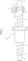
FIG. 1 is a partial cross-sectional side view illustrating a ball screw device according to a first embodiment, and depicts a cross-section of an outer ring of a rolling bearing; -
FIG. 2 is a side view partially illustrating a ball screw included in the ball screw device according to the first embodiment; -
FIG. 3 is a view on arrow A inFIGS. 1 and2 ; -
FIG. 4 is a diagram illustrating one end of a threaded shaft and the outer ring of the rolling bearing included in the ball screw device according to the first embodiment; -
FIG. 5 is a view on arrow B inFIGS. 1 and4 ; -
FIGS. 6A, 6B, and 6C are respectively a plan view, a front view, and a bottom view illustrating a lid that covers a rolling element insertion hole of the outer ring included in the ball screw device according to the first embodiment; -
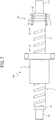
FIG. 7 is a partial cross-sectional side view illustrating a ball screw device according to a second embodiment, and depicts a cross-section of an outer ring of a rolling bearing; -
FIG. 8 is a diagram illustrating one end of a threaded shaft and an outer ring of a rolling bearing included in a ball screw device according to a third embodiment; -
FIG. 9 is a diagram illustrating one end of a threaded shaft and an outer ring of a rolling bearing included in a ball screw device according to a fourth embodiment; -
FIG. 10 is a diagram illustrating one end of a threaded shaft and an outer ring of a rolling bearing included in a ball screw device according to a fifth embodiment; -
FIG. 11 is a diagram illustrating one end of a threaded shaft and an outer ring of a rolling bearing included in a ball screw device according to a sixth embodiment; -
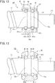
FIG. 12 is a diagram illustrating one end of a threaded shaft and an outer ring of a rolling bearing included in a ball screw device according to a seventh embodiment; -
FIG. 13 is a diagram illustrating one end of a threaded shaft and an outer ring of a rolling bearing included in a ball screw device according to an eighth embodiment; -
FIG. 14 is a diagram that describes a problem that the ball screw device according to the eighth embodiment can solve; -
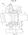
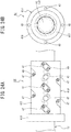
FIG. 15 is a diagram illustrating one end of a threaded shaft and an outer ring of a rolling bearing included in a ball screw device according to a ninth embodiment and a state of the ball screw device attached to a housing; -
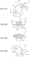
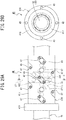
FIG. 16A is a front view illustrating a detent that connects the two divided parts of the rolling bearing included in the ball screw device according to the ninth embodiment; -
FIG. 16B is a cross-sectional view of the detent along a line b-b inFIG. 16A ; -
FIG. 17 is a partial enlarged view ofFIG. 15 ; -
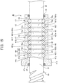
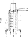
FIG. 18 is a partial cross-sectional side view illustrating a ball screw device according to a tenth embodiment, and depicts a cross-section of an outer ring of a rolling bearing; -
FIG. 19 is an enlarged cross-sectional view illustrating the rolling bearing included in the ball screw device according to the tenth embodiment; -
FIGS. 20A and 20B are respectively a plan view and a side view illustrating the rolling bearing included in the ball screw device according to the tenth embodiment; -
FIG. 21 is a diagram illustrating a lid that covers a rolling element insertion hole of the outer ring included in the ball screw device according to the tenth embodiment, an eleventh embodiment and a sixteenth embodiment, andFIG. 21A is a plan view,FIG. 21B is a view on arrow b inFIG. 21A and is partially a cross-sectional view of the lid along a line B-B inFIG. 21A, FIG. 21C is a cross-sectional view of the lid along a line C-C inFIG. 21A, and FIG. 21D is a bottom view; -
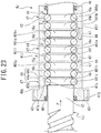
FIG. 22 is a partial cross-sectional side view illustrating a ball screw device according to the eleventh embodiment, and depicts a cross-section of an outer ring of a rolling bearing; -
FIG. 23 is an enlarged cross-sectional view illustrating the rolling bearing included in the ball screw device according to the eleventh embodiment; -
FIGS. 24A and 24B are respectively a plan view and a side view illustrating the rolling bearing included in the ball screw device according to the eleventh embodiment; -
FIG. 25 is an enlarged cross-sectional view illustrating a rolling bearing included in a ball screw device according to a twelfth embodiment; -
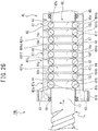
FIG. 26 is an enlarged cross-sectional view illustrating a rolling bearing included in a ball screw device according to a thirteenth embodiment; -
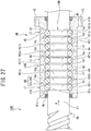
FIG. 27 is an enlarged cross-sectional view illustrating a rolling bearing included in a ball screw device according to a fourteenth embodiment; -
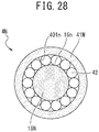
FIG. 28 is a diagram illustrating a rolling bearing included in a ball screw device according to a fifteenth embodiment, and depicts a cross-section perpendicular to an axis direction; -
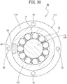
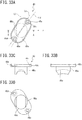
FIGS. 29A and 29B are respectively a plan view and a side view illustrating a rolling bearing included in a ball screw device according to the sixteenth embodiment; -
FIG. 30 is a cross-sectional view of the rolling bearing along a line C-C inFIG. 29 ; -
FIG. 31 is a diagram illustrating a holding piece included in the rolling bearing inFIG. 29 , andFIGS. 31A, 31B, and 31C are a front view, a side view, and a cross-sectional view along a line A-A inFIG. 31A , respectively; -
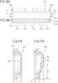
FIG. 32 is an enlarged cross-sectional view illustrating a rolling bearing included in a ball screw device according to a seventeenth embodiment; -
FIG. 33 is a diagram illustrating a lid that covers a rolling element insertion hole of an outer ring included in the ball screw device according to the seventeenth embodiment, andFIG. 33A is a plan view,FIG. 33B is a view on arrow b inFIG. 33A, FIG. 33C is a front view, andFIG. 33D is a bottom view; -
FIGS. 34A and 34B are respectively a plan view and a side view illustrating the rolling bearing included in the ball screw device according to the seventeenth embodiment; -
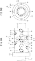
FIG. 35 is an enlarged cross-sectional view illustrating a rolling bearing included in a ball screw device according to an eighteenth embodiment; -
FIG. 36 is a diagram illustrating a lid that covers a rolling element insertion hole of an outer ring included in the ball screw device according to the eighteenth embodiment, andFIG. 36A is a plan view, andFIG. 36B is a cross-sectional view along a line A-A inFIG. 36A ; -
FIG. 37 is a partial cross-sectional side view illustrating an example of a seal of a rolling bearing included in a ball screw device according to a nineteenth embodiment; -
FIG. 38 is a diagram illustrating a rolling bearing included in a ball screw device according to a twentieth embodiment; -
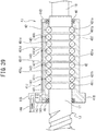
FIG. 39 is an enlarged cross-sectional view illustrating a rolling bearing (a rolling bearing having a greasing structure) included in a ball screw device according to a twenty-second embodiment, and is a diagram illustrating an example where an outer ring is provided with the greasing structure; -
FIG. 40 is an enlarged cross-sectional view illustrating the rolling bearing included in the ball screw device according to the twenty-second embodiment, and is a diagram illustrating an example where a threaded shaft is provided with the greasing structure; -
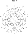
FIG. 41 is an enlarged cross-sectional view illustrating the rolling bearing included in the ball screw device according to the twenty-second embodiment, and is a diagram illustrating another example where the outer ring is provided with the greasing structure; -
FIG. 42 is a plan view illustrating the rolling bearing included in the ball screw device according to the twenty-second embodiment, and is a diagram illustrating an example where a lid is provided with the greasing structure; -
FIG. 43 is a partially cutaway enlarged cross-sectional view illustrating the rolling bearing included in the ball screw device according to the twenty-second embodiment, and is a diagram illustrating an example where a raceway groove is provided with the greasing structure; -
FIG. 44 is a diagram illustrating an example where a lid insertion hole of the outer ring is provided with the greasing structure in the rolling bearing included in the ball screw device according to the twenty-second embodiment, andFIG. 44A depicts an engagement portion, andFIG. 44B is a partial enlarged view ofFIG. 44A ; -
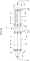
FIG. 45 is a partial cross-sectional side view illustrating a ball screw device (a ball screw device having a cooling mechanism) according to a twenty-third embodiment, and depicts a cross-section of a portion of an outer ring of a rolling bearing; and -
FIG. 46 is a diagram illustrating the rolling bearing included in the ball screw device according to the twenty-third embodiment, and illustrates an example of a connection structure of through holes through which a coolant passes that is different from the example ofFIG. 45 . - As described above, a ball screw device according to an aspect of the present invention has the foregoing Configurations (1) to (3); however, besides these, it can have any of the following Configurations (4) to (14) and (21) to (28).
- (4) The rolling bearing is subjected to a preload.
- (5) The ball screw device includes multiple rows of inner ring raceway grooves and multiple rows of outer ring raceway grooves; the groove cross-sectional shape of the inner ring raceway grooves and the outer ring raceway grooves is a single arc or Gothic arc shape.
- (6) The ball screw device has Configuration (5), and includes two rows of inner ring raceway grooves and two rows of outer ring raceway grooves; the rolling bearing is subjected to a preload by an offset preloading method.
- (7) The ball screw device has Configuration (5), and includes two rows of inner ring raceway grooves and two rows of outer ring raceway grooves; the outer ring is composed of two divided parts into which the outer ring is divided between the two outer ring raceway grooves; the rolling bearing is subjected to a preload by a spacer provided between the two divided parts.
- (8) The ball screw device has Configuration (5), and includes two rows of inner ring raceway grooves and two rows of outer ring raceway grooves; the rolling bearing is subjected to a preload by an oversized ball method.
- (9) An outer circumferential surface of the outer ring is a spherical surface.
- (10) The ball screw device has Configuration (5), and includes two rows of inner ring raceway grooves and two rows of outer ring raceway grooves; the outer ring is composed of two divided parts into which the outer ring is divided between the two rows of outer ring raceway grooves, and the two divided parts are provided with a groove on their axial end surface in contact with each other; a detent provided in a space formed by these grooves restrains the two divided parts from moving both in a radial direction and in an axial direction.
- (11) The outer ring has a small diameter portion and a large diameter portion that differ in outer diameter; the large diameter portion has an axial end surface in contact with an axial end surface of a housing to which the outer ring is attached; the small diameter portion has an outer circumferential surface in contact with an inner circumferential surface of the housing; a corner formed by a small-diameter-portion-side axial end surface of the large diameter portion and the outer circumferential surface of the small diameter portion has an undercut.
- (12) The outer diameter of the outer circumferential surface of the threaded shaft is the same between a portion provided with the helical groove and a portion provided with the inner ring raceway groove.
- (13) The ball screw device has Configuration (12), and a retained austenite amount γRS [volume%] of a surface (a surface part) of the threaded shaft satisfies the following Equation (1) in the portion provided with the helical groove and the portion provided with the inner ring raceway groove.

(In the above equation, αs denotes the ratio of a life of the helical groove of the threaded shaft to the required life of the ball screw device, and αs is greater than 1.) - (14) The ball screw device has Configuration (12), and a retained austenite amount γRS [volume%] of the surface (the surface part) of the threaded shaft satisfies the foregoing Equation (1) in a range from the portion provided with the inner ring raceway groove to the portion provided with the helical groove in the axial direction.
- (21) The second balls are made of metal or ceramics.
- (22) The ball screw device includes three or more rows of inner ring raceway grooves and three or more rows of outer ring raceway grooves. That is, the rolling bearing has three or more rows of raceways.
- (23) The ball screw device is used for applying an axially non-uniform load to the rolling bearing (for example, in a case where the nut is fixed to a linear moving part of an electric injection molding machine or a press machine, and is subjected to a high load), and has Configuration (22); the rolling bearing has a structure of suppressing non-uniformity of the amount of axial deformation caused by the load. Furthermore, of the three or more rows of raceways, one row (on the side farther away from a point of application of the load) is set as a raceway for preload application, and the other rows (on the side close to the point of application of the load) are set as a raceway for load bearing. Accordingly, the load acting per row of raceway for load bearing in the rolling bearing is reduced, thus it is possible to lengthen the life of the rolling bearing.
- (24) The ball screw device is used for applying an axially non-uniform load to the rolling bearing, and has Configuration (22); the amount of preload applied to the rolling bearing is smaller on, of the multiple rows of raceways for load bearing, a raceway on the side closer to the point of application of the load than a raceway on the side farther away from the point of application of the load. In a case where the same amount of preload is applied to all the multiple raceways for load bearing, the amount of deformation of the rolling bearing is larger on the raceway on the side closer to the point of application of the load than the raceway on the side farther away from the point of application of the load; however, such differences in amount of preload on the raceways for load bearing improves non-uniformity of the amount of axial deformation of the rolling bearing as compared with a case where all the raceways for load bearing are subjected to the same amount of preload.
- (25) The ball screw device is used for applying an axially non-uniform load to the rolling bearing, and has Configuration (22); the second balls on, of the multiple rows of raceways for load bearing, a raceway on the side closer to the point of application of the load has a larger diameter than the other raceways. Accordingly, as compared with a case where the second balls on all the raceways have the same dimensions, the load capacity of the raceway on the side closer to the point of application of the load is increased, and the life of the raceway on the side closer to the point of application of the load becomes longer, which makes the life of the entire rolling bearing longer.
- (26) The ball screw device is used for applying an axially non-uniform load to the rolling bearing, and has Configuration (22); respective rows of axially adjacent rolling element insertion holes on the outer ring are arranged in different circumferential positions on the outer ring. Accordingly, as compared with a case where all rows of rolling element insertion holes are arranged in the same circumferential position of the outer ring, it is possible to suppress non-uniform deformation of the outer ring in a plane perpendicular to the axis when subjected to an axial load. Furthermore, the rows of rolling element insertion holes are evenly arranged in a circumferential direction of the outer ring, thus it is possible to uniformize the deformation of the outer ring in the plane perpendicular to the axis when subjected to an axial load.
- (27) The ball screw device is used for applying an axially non-uniform load to the rolling bearing, and has Configuration (22); the outer ring has a flange, and the flange is provided on a portion of an end provided with no outer ring raceway grooves on the side opposite to the point of application of the load or in a range from a position second closest to the point of application of the load to a position farthest away from the point of application of the load on the multiple rows of outer ring raceway grooves for load bearing. Accordingly, as compared with a case where the flange is provided in a position closest to the point of application of the load, non-uniformity of the amount of axial deformation of the rolling bearing is improved.
- (28) The ball screw device is used for applying an axially non-uniform load to the rolling bearing, and has Configuration (22); in a cross-section perpendicular to the axial direction of the rolling bearing, the cross-sectional area of the outer ring in a groove bottom position of the outer ring raceway grooves and the cross-sectional area of a portion of the threaded shaft provided with the inner ring raceway grooves in a groove bottom position of the inner ring raceway grooves are the same. Accordingly, as compared with a case where there is a difference between the two cross-sectional areas, a difference in the amount of deformation between the outer ring and the portion of the threaded shaft provided with the inner ring raceway grooves can be reduced.
- As a result of a study on the increase of the life of a ball screw device, it turned out that a short-stroke ball screw device (that was used, for example, with a stroke factor fs of less than 4.8) is damaged mostly due to flaking of the threaded shaft of all components. Configurations (13) and (14) are based on this.
- Furthermore, it turned out that setting the retained austenite amount of the surface of the helical groove of the threaded shaft to be larger than the retained austenite amounts of respective surfaces of the helical groove of the nut and the first balls was effective.
- That is, we concluded that a combination of the threaded shaft, the nut, and the first balls composing a ball screw part should be defined by a magnitude relationship of the retained austenite amount of the surface.
- Based on this, in the ball screw device having Configuration (13) and the ball screw device having Configuration (14), a retained austenite amount γRN [volume%] of the surface of the helical groove of the nut preferably satisfies the following Equation (2).

- (In the above equation, αN denotes the ratio of a life of the helical groove of the nut to the required life of the ball screw device, and αN is greater than 1.)
- Furthermore, in the ball screw device having Configuration (13) and the ball screw device having Configuration (14), the retained austenite amount γRS of the surface of the helical groove of the threaded shaft and the retained austenite amount γRN of the surface of the helical groove of the nut are preferably in a relationship of "γRS > γRN".
- Moreover, in the ball screw device having Configuration (13) and the ball screw device having Configuration (14), the retained austenite amount γRS of the surface of the helical groove of the threaded shaft, the retained austenite amount γRN of the surface of the helical groove of the nut, and a retained austenite amount γRB of the surfaces of the first balls are preferably in a relationship of "γRS > γRN > γRB".
- Furthermore, the ball screw device having Configuration (13) and the ball screw device having Configuration (14) are useful as a ball screw device for an electric injection molding machine, an electric servo press machine, an electric actuator, a servo cylinder, or an electric jack.
- In the following description, a "thread groove surface" means a "surface of the helical groove".
- According to the ball screw device having Configuration (13) and the ball screw device having Configuration (14), a longer life can be achieved by defining the retained austenite amounts of respective thread groove surfaces of the threaded shaft and the nut that are components of the ball screw device and defining a magnitude relationship of the two. Furthermore, all it takes is to set the retained austenite amount of the thread groove surface of the threaded shaft to be larger than those of the other components, thus conventional products can be used as the nut and the first balls, and therefore it is possible to increase production efficiency of the ball screw device and to suppress an increase in cost of the ball screw device.
- Examples of the ball screw device used with a stroke factor fs of less than 4.8 include an electric injection molding machine, an electric servo press machine, a servo cylinder, an electric jack, etc., and the ball screw device having Configuration (13) and the ball screw device having Configuration (14) are useful for these.
It is to be noted that a similar effect is obtained in a case of a roller screw device that uses a roller instead of the first balls. - In the ball screw device having Configuration (13) and the ball screw device having Configuration (14), a retained austenite amount γRS [volume%] of the thread groove surface of the threaded shaft satisfies the following Equation (1).

- (In the above equation, αs denotes the ratio of a life of the helical groove of the threaded shaft to the required life of the ball screw device, and αs is greater than 1.)
- Furthermore, a retained austenite amount γRN [volume%] of the thread groove surface of the nut preferably satisfies the following Equation (2).

- (In the above equation, αN denotes the ratio of a life of the helical groove of the nut to the required life of the ball screw device, and αN is greater than 1.)
- In the ball screw device under a normal operating condition, unlike the rolling bearing, skidding between the balls and a raceway surface (the helical groove composing the helical raceway) of the threaded shaft or the nut due to twisting of the raceway is large, thus the form of raceway surface failure due to rolling contact fatigue is surface originated flaking. There is a correlation between the occurrence or development of failure leading to this surface originated flaking and the retained austenite amount γR of the surface of the raceway surface, and achievement of a life increasing effect can be expected by increasing the retained austenite amount γR of the surface of the raceway surface more than usual.
- Then, to quantitatively evaluate the life increasing effect made by an increase in the retained austenite amount γR, the present inventors experimentally examined a surface originated flaking life, using various induction-heat-treated component test specimens that differ in retained austenite amount γR of the surface of the raceway surface. Also, a surface originated flaking life (a conventional life) in a case of using a conventional threaded shaft material (SAE4150) was examined by the same method.
- As a result, it turned out that the following Relational Expression (11) held true between the retained austenite amount γR [volume%] of the surface of each test specimen made of an induction-heat-treated material and a ratio α of a life of the test specimen to the conventional life.

- From Expression (11), it can be seen that to achieve a longer life (α>1) than the conventional ball screw device, the retained austenite amount γR of the thread groove surface of the threaded shaft needs to be greater than 9% by volume. Furthermore, it can also be seen that an optimum retained austenite amount γR that allows to achieve exactly a required life not too long or too short from the life required of the ball screw device can be estimated from Expression (11).
- Incidentally, if the ball screw device with a static load in the axial direction is driven by rotation of the threaded shaft, the nut moves in a linear direction relative to the threaded shaft. At this time, an arbitrary spot of the raceway surface of the nut is subjected to repeated stress due to the passage of the balls with the load applied. Meanwhile, in the threaded shaft, a portion to be the raceway surface (the helical groove composing the helical raceway) moves in the axial direction in accordance with the linear movement of the nut. That is, in the threaded shaft, a portion subjected to repeated stress due to the passage of the balls with the load applied becomes part in the axial direction.
- Therefore, in a case where the stroke of the nut is sufficiently long, the number of repetitions of stress that the raceway surface is subjected to through the passage of the balls with the load applied is increased more on the nut side than the threaded shaft side, thus it is known that the first rolling fatigue failure occurs on the raceway surface of the nut. Accordingly, in the conventional technology, the retained austenite amount γR of the thread groove surface of the nut is set to be larger than the retained austenite amount γR of the thread groove surface of the threaded shaft.
- However, in the ball screw device used in an electric injection molding machine or the like, the stroke of the nut is short, thus a magnitude relationship of the number of repetitions of stress on the raceway surface with the passage of the balls with the load applied is reversed, and the number of repetitions of stress on the threaded shaft side is larger than on the nut side. Therefore, in a ball screw endurance test under a short-stroke operating condition, it was confirmed that the first rolling fatigue failure tended to occur on the threaded shaft side.
- Furthermore, the fact that contact surface pressure between the balls and the raceway surface is increased more on the threaded shaft side than the nut side is also evidence to support the result that a position of the first failure deflected to the threaded shaft side.
- Based on the failure characteristic of the raceway surface of the threaded shaft and the nut due to the contact surface pressure and the number of repetitions of stress as described above, the fatigue life of the raceway surface is inversely proportional to the ninth power of the contact surface pressure and also inversely proportional to the number of repetitions of stress; therefore, a life ratio β of the nut raceway surface to the threaded shaft raceway surface can be represented by the following Equation (12).

- In the above equation, PS and PN denote respective contact surface pressures on the raceway surfaces of the threaded shaft and the nut; NS and NN denote the respective numbers of repetitions of stress on the raceway of the threaded shaft and the nut during one-stroke operation.
- Then, to examine the life ratio β of the raceway surface of the nut to the raceway surface of the threaded shaft in the ball screw device under an actual use condition, PS and PN and NS and NN were found from the respective axial loads and strokes of ball screw devices for a total of twenty models of electric injection molding machines having put to practical use. Furthermore, β of each model was calculated by substituting these values into Equation (12).
- As a result, it turned out that the following Relational Expression (13) held true between the life ratio β and the stroke factor fs. The stroke factor fs is a value obtained by dividing the stroke (St) by the product of the number of active turns (ζ), the number of circuits (ξ), and the lead (1) of the ball screw device as illustrated in Equation (14).


- From Expression (13), it can be seen that in a case of the ball screw device driven under a condition that allows a short stroke (fs<4.8) such as that of an electric injection molding machine, the life of the raceway surface of the nut is longer than that of the threaded shaft (β>1).
- Therefore, for further improvement of the productivity, it is desirable that the retained austenite amounts γR of the respective thread groove surfaces of the threaded shaft and the nut be determined to satisfy the required life of the ball screw device, taking into consideration the relationship of the raceway surface life between the threaded shaft and the nut in a case where the above-described stroke factor fs is less than 4.8.
- Accordingly, using and Expressions (11) and (13), respective retained austenite amounts γRS and γRN necessary for the thread groove surfaces of the threaded shaft and the nut are estimated.
- As described above, Expression (11) is an expressions obtained through experiments on the threaded shaft. Therefore, the retained austenite amount γRS
- [volume%] of the thread groove surface of the threaded shaft is represented by the following Equation (15) that is modified from Expression (11) by replacing α in Expression (11) with αs; αs denotes the life ratio of the threaded shaft raceway groove to the ball screw device.

- Furthermore, the life ratio β of the nut raceway surface to the threaded shaft raceway surface is represented by "β = αN/αS", where αS denotes the life ratio of the threaded shaft raceway surface to the ball screw device, and αN denotes the life ratio of the nut raceway surface to the ball screw device. By modifying this equation by substituting the right side of Expression (13) into β and substituting the right side of Expression (11) into αS in this equation, the retained austenite amount γRN [volume%] of the thread groove surface of the nut is represented by the following Equation (16).

- Therefore, the retained austenite amounts γRS and γRN of the respective thread groove surfaces of the threaded shaft and the nut that allow the life of the threaded shaft raceway surface to be coincident with the life of the nut raceway surface can be estimated by substituting "αS = αN = α >1" into Equations (15) and (16).
- That is, to increase the life (α>1) of the ball screw device used with a stroke factor fs of less than 4.8, it is reasonable to combine the threaded shaft and the nut so that the retained austenite amount γRS of the threaded shaft thread groove surface represented by Equation (15) is larger than the retained austenite amount γRN of the nut thread groove surface represented by Equation (16).
- As described above, one of preferred forms of an aspect of the ball screw device is that the retained austenite amounts γRS and γRN of the thread groove surfaces (the surfaces of the helical grooves) of the threaded shaft and the nut meet Equations (1) and (2), respectively, and more preferably, if "γRS > γRN", raw materials of the threaded shaft and the nut are not limited.
- However, from a standpoint of the productivity of the ball screw device, application of induction heat treatment to the threaded shaft is the mainstream; therefore, to set the retained austenite amount γRS of the thread groove surface of the threaded shaft as described above, of materials suitable for the induction heat treatment, high-carbon bearing steel is preferable as a material of the threaded shaft.
- Furthermore, it is preferable that the nut be subjected to carbonitriding treatment using case hardening steel as in a conventional way. By using a conventional nut as it is, the entire ball screw device can be produced inexpensively.
- It is to be noted that a known method for induction heat treatment can be adopted. In that case, an output of an induction heating coil is controlled in a state of being devised to prevent overheat.
- Moreover, as for the balls (the first balls, the rolling elements) that are another component of the ball screw device, since the balls rotate randomly, it is difficult to calculate their life by the same criteria. However, the balls rotate randomly, thus their surfaces in contact with the raceway surfaces of the threaded shaft and the nut change from moment to moment. Thus, the number of times each portion of the rolling contact surfaces of the balls is subjected to a load is less frequent as compared with the raceway surfaces of the threaded shaft and the nut, and therefore the balls have a longest life.
- Therefore, the retained austenite amount γRB of the surfaces of the balls is preferably smaller than those of the threaded shaft and the nut.
- That is, a magnitude relationship of the retained austenite amounts γR of the three, including the balls, is preferably "γRS > γRN > γRB". If these three satisfy the magnitude relationship, the balance of feature and productivity can be maximized even in a case where any of the components is damaged.
- It is to be noted that conventional products can be used as the balls. By using conventional products, i.e., for example, products made from bearing steel by immersion quenching as the balls, it is possible to suppress an increase in cost of the ball screw device.
- In recent years, there is an increasing need for a high-cycle and environment-friendly high-load machine such as an injection molding machine, and increase in the life and improvement of the durability are expected in a drive shaft.
- A ball screw for high load application such as an injection molding machine is designed to cause a high load to be applied in a fixed direction. In a general ball screw, a small diameter portion (a portion having a smaller outer diameter than the portion provided with the helical groove) is provided on both axial ends of the threaded shaft to form a surface that an angular ball bearing or the like comes into contact with. That is, the threaded shaft is subjected to a stepped cutting process by cutting or grinding.
- This small diameter portion serves as a bearing support portion; however, the bearing support portion is designed to be interference so that the inner ring does not to creep into the bearing support portion, and therefore its axial end surface that the outer circumferential surface and the bearing come in contact with is in a ground state in most cases. Accordingly, an undercut or an R-shaped corner is formed on the bearing support portion, and this corner becomes structural weakness. Therefore, in high axial load application, it is necessary to take a measure to prevent this corner from being subjected to the concentration of stress and thus being damaged.
- As this measure, the bearing support portion is formed into not the small diameter portion but a flange having a larger outer diameter than the portion provided with the helical groove, and an axial end surface of the bearing is pressed against this flange surface. However, in this measure, when the threaded shaft is produced, to make the outer diameter of a portion other than the flange portion smaller, a process of cutting and grinding a portion (the portion provided with the helical groove) on the side closer to the axially center than the flange portion and the axial end is performed on a bar for the threaded shaft, thus the processing cost is increased.
- On the other hand, if the bearing support portion (the axial end) of the threaded shaft is configured to be the same as the portion provided with the helical groove, and the retained austenite amount γRS of the surface of the threaded shaft including the bearing support portion is configured to meet the foregoing Equation (1), it is possible to prevent the concentration of stress on the bearing support portion without having to increase the processing cost.
- Furthermore, in the ball screw device according to the aspect of the present invention, if the retained austenite amount γRS of the surface of the threaded shaft is configured to meet the foregoing Equation (1) on the portion provided with the helical groove and the portion provided with the inner ring raceway groove, the durability of the ball screw device is improved.
- In the following, embodiments of the present invention will be described; however, the invention is not limited to the embodiments described below. In the embodiments described below, technologically preferred limitations are made to embody the invention; however, these limitations are not requirements of the invention.
- As illustrated in
FIGS. 1 to 5 , aball screw device 10 according to a first embodiment includes a ball screw that includes a threadedshaft 1 having ahelical groove 11 on its outer circumferential surface, anut 2 having ahelical groove 21 on its inner circumferential surface, and balls (first balls) 3. Both ends of the threadedshaft 1 are each processed into asmall diameter portion 111 having a smaller diameter than a portion provided with the helical groove. On oneaxial end 12 of the threadedshaft 1 on the side connected to a motor (on the right end side inFIG. 1 ), a rollingbearing 4 is installed in a portion provided with no helical grooves between thesmall diameter portion 111 and the portion provided with the helical groove. The otheraxial end 13 of the threadedshaft 1 is also provided with thesmall diameter portion 111. - As illustrated in
FIGS. 2 and 3 , thenut 2 is composed of acylindrical portion 2A and aflange portion 2B. Theflange portion 2B is provided with bolt insertion holes 22 that penetrate in the axial direction. - As illustrated in
FIG. 4 , the rollingbearing 4 is composed of two rows of innerring raceway grooves axial end 12 of the threadedshaft 1, anouter ring 41 having outerring raceway grooves ring raceway grooves multiple balls 42 are rollably arranged between the innerring raceway grooves ring raceway grooves multiple balls 42 are made of metal or ceramics. - Furthermore, the rolling
bearing 4 is a full-ball bearing without a cage. It is to be noted that synthetic resin or metal spacer-balls or synthetic resin holding pieces may be provided between theballs 42. - Moreover, the groove cross-sectional shape of the inner
ring raceway grooves ring raceway grooves bearing 4 is subjected to a back to back duplex (DB) preload by the offset preloading method. That is, L1 is greater than L2. - Furthermore, the
outer ring 41 is composed of afirst raceway portion 41a provided with the outerring raceway groove 401a and asecond raceway portion 41b provided with the outerring raceway groove 401b. An outer edge (a portion projecting outward from thefirst raceway portion 41a) 41c of thesecond raceway portion 41b is provided with bolt insertion holes 43 that penetrate in the axial direction. The first andsecond raceway portions element insertion hole 44 penetrating from their outer circumferential surface to the outerring raceway groove lid 45. - As illustrated in
FIG. 6 , thelid 45 is composed of ashaft 45a and ahead 45b, and a distal end surface (an inner surface of a lid portion) 45c of theshaft 45a is formed into a concave shape to serve as part of the outerring raceway groove FIG. 4 , the rollingelement insertion hole 44 is composed of aninside portion 44a having a shape fitted with theshaft 45a and anoutside portion 44b having a shape fitted with thehead 45b. - The
lid 45 is secured not to come out of the rollingelement insertion hole 44 with a C-shaped snap ring or an adhesive after theballs 42 have been put between the innerring raceway grooves ring raceway grooves - The
ball screw device 10 is used by fixing thenut 2 to a member to be linearly moved, fixing theouter ring 41 of the rollingbearing 4 to a base through a housing, and connecting the motor to thesmall diameter portion 111 of the oneaxial end 12 of the threadedshaft 1. With thefirst raceway portion 41a put into the housing, and thesecond raceway portion 41b pressed against an axial end surface of the housing, theouter ring 41 is fixed to the housing with bolts put through the bolt insertion holes 43 of thesecond raceway portion 41b. It is to be noted that, for example, a deep groove ball bearing is attached to thesmall diameter portion 111 of the otheraxial end 13, and its outer ring is fixed to the base through the housing. - In the
ball screw device 10 according to the first embodiment, the rollingbearing 4 with the preload applied is integral with a ball screw; therefore, by applying a preload depending on a requirement to the rollingbearing 4 in advance, the need for a preload adjustment is eliminated when theball screw device 10 is installed in a machine tool or the like at the client's. - In a case where the application of a preload is performed at the client's, an assembly accuracy error may increase, which may reduce the rotation accuracy. On the other hand, the
ball screw device 10 according to the first embodiment does not require a preload adjustment when theball screw device 10 is installed in a machine tool or the like at the client's; therefore, it is not necessary to worry about reduction of the rotation accuracy associated with a preload adjustment. - Furthermore, in the
ball screw device 10, themultiple balls 42 are made of metal or ceramics; therefore, the rollingbearing 4 is durable. - Moreover, the
outer ring 41 is provided with the rolling element insertion holes 44; therefore, theballs 42 can be easily inserted between the innerring raceway grooves ring raceway grooves outer ring 41. Accordingly, after the outerring raceway grooves ring raceway grooves outer ring 41 on the oneaxial end 12 of the threadedshaft 1, theballs 42 can be arranged between the two raceway grooves. - Accordingly, it is possible to reduce the trouble of having to assemble the rolling bearing as compared with a ball screw device where the
outer ring 41 embedded with theballs 42 has to be put on the oneaxial end 12 of the threadedshaft 1. Furthermore, the load capacity of the rollingbearing 4 in the axial direction and the radial direction can also be changed by changing the diameter of theballs 42 used without modifying the innerring raceway grooves ring raceway grooves - Moreover, the distal end surfaces 45c of the lids are formed into a concave shape to serve as part of the outer
ring raceway grooves bearing 4. - As illustrated in
FIG. 7 , in aball screw device 10A according to a second embodiment, a rollingbearing 4A is subjected to a face to face duplex (DF) preload by the offset preloading method. That is, inFIG. 4 , L1 is less than L2. Except for this, theball screw device 10A has the same configuration as theball screw device 10 according to the first embodiment. - As illustrated in
FIG. 8 , in aball screw device 10B according to a third embodiment, a single-row rolling bearing 4B is used; a preload depending on a requirement has been applied to the rollingbearing 4B by, for example, the oversized ball method in advance. Except for this, theball screw device 10B has the same configuration as theball screw device 10 according to the first embodiment. - As illustrated in
FIG. 9 , in a ball screw device 10C according to a fourth embodiment, a single-row rolling bearing 4C is used; a preload depending on a requirement has been applied to the rolling bearing 4C by, for example, the oversized ball method in advance. Furthermore, the threaded shaft is not provided with thesmall diameter portion 111. Except for these, the ball screw device 10C has the same configuration as theball screw device 10 according to the first embodiment. - As illustrated in
FIG. 10 , in a ball screw device 10D according to a fifth embodiment, a single-row rolling bearing 4D is used; a preload depending on a requirement has been applied to the rollingbearing 4D by, for example, the oversized ball method in advance. Furthermore, the threaded shaft is not provided with thesmall diameter portion 111 and is provided with the innerring raceway groove 12a on a portion of the outer circumferential surface of the oneaxial end 12 where thehelical groove 11 has been formed. Except for these, the ball screw device 10D has the same configuration as theball screw device 10 according to the first embodiment. - As illustrated in
FIG. 11 , in aball screw device 10E according to a sixth embodiment, anouter ring 41E of a rolling bearing 4E is composed of two dividedparts outer ring 41E is divided between the two rows of outerring raceway grooves spacer 413 is provided between the two dividedparts bearing 4E is subjected to a preload by thespacer 413 generating a force that widens a space between the two dividedparts ball screw device 10E has the same configuration as theball screw device 10 according to the first embodiment. - As illustrated in
FIG. 12 , in aball screw device 10F according to a seventh embodiment, the diameter of theballs 42 of a rolling bearing 4F is configured to be greater than a distance between facing arcs of groove normal sections formed by the outerring raceway grooves ring raceway grooves ball screw device 10F has the same configuration as theball screw device 10 according to the first embodiment. - As illustrated in
FIG. 13 , in aball screw device 10G according to an eighth embodiment, an outer circumferential surface of anouter ring 41G of a rollingbearing 4G is a spherical surface. Accordingly, theouter ring 41G has a property of aligning with the housing. Except for this, theball screw device 10G has the same configuration as theball screw device 10 according to the first embodiment. - A ball screw installation error includes, specifically, a tilt error illustrated in
FIG. 14A and a misalignment error illustrated inFIG. 14B . The tilt error causes a moment load, and the misalignment error causes a radial load. Theouter ring 41G has the aligning property, and therefore can absorb a moment load or a radial load caused by such a ball screw installation error when theball screw device 10 is in use. - Accordingly, the
ball screw device 10G according to the eighth embodiment can achieve effects of improving the durability, the torque characteristics, and the feeding accuracy in addition to the effects that theball screw device 10 according to the first embodiment has. - As illustrated in
FIG. 15 , in aball screw device 10H according to a ninth embodiment, anouter ring 41H of arolling bearing 4H is composed of the two dividedparts outer ring 41H is divided between the two rows of outerring raceway grooves outer ring 41H has adetent 6 that connects the two dividedparts - The first divided
part 411 has an outercircumferential surface 411a fitted into an innercircumferential surface 51 of ahousing 5. The second dividedpart 412 is composed of alarge diameter portion 414 having an outer diameter larger than that of the first dividedpart 411 and asmall diameter portion 415 having the same outer diameter as the first dividedpart 411. Thesmall diameter portion 415 has an outercircumferential surface 415a fitted into the innercircumferential surface 51 of thehousing 5. - As illustrated in
FIG. 16 , thedetent 6 is a partially opened annular member, and has acircumferential groove 61 on the center of its inner circumferential surface in a width direction. Examples of a material of thedetent 6 include carbon steel, stainless steel, beryllium copper, Inconel, etc. Furthermore, in a case where fretting does not occur between the housing and the outer ring, synthetic resin such as POM can also be used. - As illustrated in
FIG. 17 , the first dividedpart 411 has a notch (a groove) 411c extending to the outercircumferential surface 411a on an entire outer circumferential surface of anaxial end surface 411b in contact with the second dividedpart 412. Furthermore, a radially outwardly projectingconvex portion 411d is formed on the side of theaxial end surface 411b of thenotch 411c. Accordingly, with the first dividedpart 411 fitted into the innercircumferential surface 51 of thehousing 5, agroove 54 is formed by the innercircumferential surface 51 and thenotch 411c. - The second divided
part 412 has a notch (a groove) 412c extending to the outercircumferential surface 415a of thesmall diameter portion 415 on an entire outer circumferential surface of anaxial end surface 412b in contact with the first dividedpart 411. Furthermore, a radially outwardly projectingconvex portion 412d is formed on the side of theaxial end surface 412b of thenotch 412c. Accordingly, with thesmall diameter portion 415 of the second dividedpart 412 fitted into the innercircumferential surface 51 of thehousing 5, agroove 55 is formed by the innercircumferential surface 51 and thenotch 412c. - Furthermore, the second divided
part 412 has an undercut 416 at a corner formed by anaxial end surface 414b of thelarge diameter portion 414 on the side of thesmall diameter portion 415 and the outercircumferential surface 415a of thesmall diameter portion 415. - The
convex portion 411d of the first dividedpart 411 and theconvex portion 412d of the second dividedpart 412 have the same dimensions, and a total value of respective widths of these convex portions is slightly greater than the width of thecircumferential groove 61 of thedetent 6. Accordingly, the axial end surfaces 411b and 412b of the first and second dividedparts detent 6 is opened, and then theconvex portions circumferential groove 61, thus the two dividedparts detent 6. - Furthermore, the rolling
bearing 4H is subjected to a DF preload by the offset preloading method. - Except for these described above, the
ball screw device 10H has the same configuration as theball screw device 10 according to the first embodiment. - When the
ball screw device 10H is in use, as illustrated inFIG. 15 , the first dividedpart 411 of theouter ring 41H with the two dividedparts detent 6 and thesmall diameter portion 415 of the second dividedpart 412 are fitted into the innercircumferential surface 51 of thehousing 5 fixed to abase 7, and anaxial end surface 411e on the side opposite to theaxial end surface 411b is pressed against anuneven surface 53 of thehousing 5. - Furthermore, with the
axial end surface 412b of the second dividedpart 412 facing anaxial end surface 52 of thehousing 5, theouter ring 41H is fixed to thehousing 5 with bolts inserted through bolt insertion holes provided on the outer edge of the second dividedpart 412. - It is to be noted that, for example, a deep groove ball bearing is attached to the
small diameter portion 111 of the otheraxial end 13, and its outer ring is fixed to thebase 7 through the housing. - In the
ball screw device 10H according to the present embodiment, the two dividedparts detent 6; therefore, if, with the two dividedparts housing 5, there is a gap between theaxial end surface 414b of the second dividedpart 412 of theouter ring 41H and theaxial end surface 52 of thehousing 5, it is not a problem. - Furthermore, the outer
circumferential surface 415a of thesmall diameter portion 415 of the second dividedpart 412 is fitted into the innercircumferential surface 51 of thehousing 5, and a corner formed by the innercircumferential surface 51 and theaxial end surface 52 of thehousing 5 is placed in the undercut 416, thus it is possible to easily perform alignment of theouter ring 41H. - It is to be noted that in the
ball screw device 10H according to the present embodiment, a total value of respective widths of theconvex portions parts circumferential groove 61 of thedetent 6; however, it may be equal to or slightly smaller than the width of thecircumferential groove 61 of thedetent 6. - Then, in a case where the total value of the widths is smaller than the width of the
circumferential groove 61, when theouter ring 41H is fixed to thehousing 5 with the bolts, by tightening up the bolts, theconvex portions circumferential groove 61 are moved to the side of theuneven surface 53 of thehousing 5; therefore, it is possible to bring theaxial end surface 414b of the second dividedpart 412 into close contact with theaxial end surface 52 of thehousing 5. - As illustrated in
FIG. 18 , a ball screw device 10Q according to a tenth embodiment includes a ball screw that includes a threadedshaft 1Q, thenut 2, and the balls (the first balls) 3 and anouter ring 41Q of a rollingbearing 4Q. - The threaded
shaft 1Q is divided into a helicalgroove formation portion 15 with thehelical groove 11 formed on its outer circumferential surface, a racewaygroove formation portion 16 with inner ring raceway grooves of the rollingbearing 4 formed, ascrew shank 17 between the helicalgroove formation portion 15 and the racewaygroove formation portion 16, and amotor connection end 18. The racewaygroove formation portion 16 is covered with theouter ring 41Q. Themotor connection end 18 is an axial end that continues from the racewaygroove formation portion 16 on the side opposite to thescrew shank 17. - The helical
groove formation portion 15, the racewaygroove formation portion 16, thescrew shank 17, and themotor connection end 18 have the same diameter of a circle that forms their outer circumferential surface. That is, the outer diameter of an outer circumferential surface of the threadedshaft 1Q is uniform entirely in the axial direction, except for a chamfered portion. Both ends of the threadedshaft 1Q are not subjected to a stepped cutting process. The threadedshaft 1Q does not have thesmall diameter portion 111 unlike the threadedshaft 1 illustrated inFIG. 1 . - Furthermore, an axial area A of the threaded
shaft 1Q illustrated inFIG. 18 , i.e., an area from anend 15a of the helicalgroove formation portion 15 on the side opposite to thescrew shank 17 to a boundary position of the racewaygroove formation portion 16 with themotor connection end 18 is subjected to heat treatment so that a retained austenite amount γRS [volume%] of a surface satisfies the following Equation (1). Themotor connection end 18 is subjected to induction hardening and induction tempering.
- (In the above equation, αS denotes the life ratio of the helical groove of the threaded shaft to the required life of the ball screw device, and αS is greater than 1.)
- Specifically, by using high-carbon bearing steel as a material of the threaded
shaft 1Q and subjecting the area A to induction heat treatment, a retained austenite amount γRS [volume%] of a surface of the area A satisfies the above Equation (1). - Furthermore, a material of the
nut 2 is case hardening steel, and is subjected to carbonitriding treatment. A material of theballs 3 is bearing steel, and is subjected to immersion quenching. Respective retained austenite amounts γR of the threadedshaft 1, thenut 2, and theballs 3 satisfy "γRS > γRN > γRB" • - As illustrated in
FIG. 18 , thehelical groove 21 is formed on the inner circumferential surface of thenut 2. Furthermore, thenut 2 is composed of thecylindrical portion 2A and theflange portion 2B. Theflange portion 2B is provided with a bolt insertion hole that penetrates in the axial direction. - As illustrated in
FIG. 19 , the rollingbearing 4Q is composed of nine rows of innerring raceway grooves 16a to 16i formed on the racewaygroove formation portion 16 of the threadedshaft 1Q, theouter ring 41Q having outerring raceway grooves 401a to 401i that face the innerring raceway grooves 16a to 16i, the multiple balls (the second balls) 42, and a pair ofseals 46. Themultiple balls 42 are rollably arranged between the innerring raceway grooves 16a to 16i and the outerring raceway grooves 401a to 401i. Theseals 46 are each in contact with the side of the racewaygroove formation portion 16 close to thescrew shank 17 and the motor connection end 18 of the threadedshaft 1. - As illustrated in
FIGS. 19 and20 , theouter ring 41Q is composed of acylindrical portion 417 and aflange portion 418. The outerring raceway grooves 401a to 401i are formed on thecylindrical portion 417. Theflange portion 418 is provided with the bolt insertion holes 43 that penetrate in the axial direction. Furthermore, thecylindrical portion 417 is provided with the rolling element insertion holes 44 penetrating from its outer circumferential surface to the outerring raceway grooves 401a to 401i. The nine rolling element insertion holes 44 of theouter ring 41Q are formed in positions of thecylindrical portion 417 so that each rolling element insertion hole is shifted by 90° from its axially adjacent rolling element insertion holes. Each rollingelement insertion hole 44 is covered with alid 47. - As illustrated in
FIG. 21 , thelid 47 is composed of ashaft 47a and ahead 47b, and a distal end surface (an inner surface of a lid portion) 47c of theshaft 47a is formed into a concave shape to serve as part of corresponding one of the outerring raceway grooves 401a to 401i. Thehead 47b is provided withbolt insertion holes 47d andcounterbores 47e. A straight line Lc indicating a longer direction of an ellipse that forms thehead 47b is tilted to a straight line Lt perpendicular to the axial direction of theouter ring 41Q. A cross-section of thelid 47 along a line A-A inFIG. 21A is seen inFIG. 19 . - As illustrated in
FIG. 19 , each rollingelement insertion hole 44 of theouter ring 41Q is composed of theinside portion 44a having a shape fitted with theshaft 47a of thelid 47 and theoutside portion 44b having a shape fitted with thehead 47b. Furthermore, on aboundary surface 44c between theinside portion 44a and theoutside portion 44b of the rollingelement insertion hole 44, female screws are formed at positions corresponding to thebolt insertion holes 47d of thelid 47. - As illustrated in
FIG. 19 , after theballs 42 are put into raceways composed of the innerring raceway grooves 16a to 16i and the outerring raceway grooves 401a to 401i from the rolling element insertion holes 44, thelids 47 are fitted into the rolling element insertion holes 44. After that, as illustrated inFIG. 20 , by puttingbolts 49 into thebolt insertion holes 47d and screwing thebolts 49 into the female screws of theouter ring 41Q, thelids 47 are secured not to come out of the rolling element insertion holes 44. - The rolling
bearing 4Q may be a full-ball bearing without a cage, or synthetic resin or metal spacer-balls or synthetic resin holding pieces may be provided between theballs 42. - Furthermore, illustrated in
FIG. 19 , a portion between two raceways of the rollingbearing 4Q on the side of the motor connection end 18 (raceways formed by the outerring raceway grooves 401a and 401B and the innerring raceway grooves ring raceway groove 401a and the innerring raceway groove 16a) is a raceway for preload application, and has a contact angle opposite to those of the other raceways (multiple rows of raceways for load bearing). - Then, the ball screw device 10Q is used by fixing the
nut 2 to a member to be linearly moved, fixing theouter ring 41Q of the rollingbearing 4Q to the base through the housing, and connecting the motor to the motor connection end (one axial end) 18 of the threadedshaft 1Q. With thecylindrical portion 417 put into the housing, and theflange portion 418 pressed against the axial end surface of the housing, theouter ring 41Q is fixed to the housing with the bolts put through the bolt insertion holes 43 of theflange portion 418. - For example, a deep groove ball bearing is attached to the
end 15a of the helicalgroove formation portion 15, and its outer ring is fixed to the base through the housing. - In the ball screw device 10Q according to the tenth embodiment, the rolling
bearing 4Q with the preload applied is integral with the ball screw; therefore, by applying a preload depending on a requirement to the rollingbearing 4Q in advance, the need for a preload adjustment is eliminated when the ball screw device 10Q is installed in a machine tool or the like at the client's. - In a case where the application of a preload is performed at the client's, an assembly accuracy error may increase, which may reduce the rotation accuracy. On the other hand, the ball screw device 10Q according to the tenth embodiment does not require a preload adjustment when the ball screw device 10Q is installed in a machine tool or the like at the client's; therefore, it is not necessary to worry about reduction of the rotation accuracy associated with a preload adjustment. As compared with a case where an inner ring of a rolling bearing is attached to a threaded shaft with a locknut, by not using a locknut, an effect of suppressing centrifugal whirling of a motor installation portion is also obtained. Accordingly, when the ball screw device 10Q is installed in a machine at the client's, a run-out adjustment is not necessary or is made easier.
- Furthermore, the
outer ring 41Q is provided with the rolling element insertion holes 44; therefore, theballs 42 can be easily inserted between the innerring raceway grooves 16a to 16i and the outerring raceway grooves 401a to 401i from the side of an outer circumferential surface of theouter ring 41Q. Accordingly, after the outerring raceway grooves 401a to 401i are set to face the innerring raceway grooves 16a to 16i by putting theouter ring 41Q on the oneaxial end 12 of the threadedshaft 1Q, theballs 42 can be arranged between the two raceway grooves. - Therefore, it is possible to reduce the trouble of having to assemble the rolling bearing as compared with a ball screw device where the
outer ring 41Q embedded with theballs 42 has to be put on themotor connection end 18 that is one axial end of the threadedshaft 1Q. Furthermore, the load capacity of the rollingbearing 4 in the axial direction and the radial direction can also be changed by changing the diameter of theballs 42 used without modifying the innerring raceway grooves 16a to 16i and the outerring raceway grooves 401a to 401i. - Moreover, the distal end surfaces 47c of the
lids 47 are formed into a concave shape to serve as part of the outerring raceway grooves 401a to 401i, and therefore does not hinder a function as the rollingbearing 4. - Furthermore, the ball screw device 10Q according to the tenth embodiment includes the rolling
bearing 4Q having nine rows of raceways; the nine rows of innerring raceway grooves 16a to 16i are formed on the threadedshaft 1Q, and the nine rows of outerring raceway grooves 401a to 401i are formed on oneouter ring 41Q. Accordingly, the number of components is reduced, as compared with a case where nine rolling bearings are installed, as separate components, in a ball screw. Thus, the surface of a component is not necessarily uniform, and micro-deformation is caused by contact. The ball screw device 10Q has less chance of contact between components, and therefore is less likely to have deformation, and stiffness is improved. - Moreover, in a case where the raceway
groove formation portion 16 of the threadedshaft 1 is subjected to a high load to the right-hand side inFIGS. 18 and19 when the ball screw device 10Q is in use, the rollingbearing 4Q is subjected to an axially non-uniform load (a higher load on the side axially closer to thenut 2 than the side farther away from the nut 2). In this case, in the rolling bearing 4Q, of the nine rows of raceways, eight rows of raceways other than the raceway for preload application on the side closest to themotor connection end 18 bear the load; therefore, a load per row is reduced. Accordingly, it is possible to prevent theballs 42 existing on the raceway of the rollingbearing 4Q on the side of theflange portion 418 subjected to the highest load from being damaged early. - Furthermore, the nine rows of rolling element insertion holes 44 are arranged evenly in the circumferential direction of the
outer ring 41Q, thus deformation of theouter ring 41Q in a plane perpendicular to the axis when subjected to an axial load can be uniformized. Accordingly, it is possible to increase the life of theouter ring 41Q. - In this way, in a case where a raceway groove formation portion of a threaded shaft of a ball screw device is subjected to an axially non-uniform and high load, it is preferable to reduce a load per row in such a manner that the number of raceways of a rolling bearing is three or more rows, and, of the three or more rows of raceways, one row (on the side farthest away from the point of application of the load) is set as a raceway for preload application, and the other multiple rows (on the side close to the point of application of the load) are set as a raceway for load bearing.
- Moreover, the outer diameter of the outer circumferential surface of the threaded
shaft 1Q is uniform entirely in the axial direction except for the chamfered portion, and the threadedshaft 1Q is not subjected to a stepped cutting process. This prevents the occurrence of the concentration of stress on theend 15a of the helicalgroove formation portion 15 and themotor connection end 18; therefore, as compared with a threaded shaft subjected to a stepped cutting process, stiffness to twisting or bending of theend 15a of the helicalgroove formation portion 15 and themotor connection end 18 is improved, thus the durability is improved. - Furthermore, the outer diameter of the outer circumferential surface of the threaded
shaft 1Q is the same between the helicalgroove formation portion 15 and the racewaygroove formation portion 16; therefore, as compared with a case where the outer diameter of the outer circumferential surface of the threadedshaft 1Q differs between the outer diameter of the helicalgroove formation portion 15 and the racewaygroove formation portion 16, the concentration of stress is avoided, thus the durability is improved, and the processing cost is reduced. - Moreover, there is no residual stress generated at the time of a stepped cutting process on the
end 15a of the helicalgroove formation portion 15 and themotor connection end 18; therefore, deformation does not occur on respective ends of the helicalgroove formation portion 15 and themotor connection end 18, thus the run-out accuracy of these ends becomes better. And, by not performing a stepped cutting process, the processing cost can be reduced. - Furthermore, in the ball screw device 10Q according to the tenth embodiment, in the axial area A of the threaded
shaft 1Q, i.e., in all of the helicalgroove formation portion 15, the racewaygroove formation portion 16, and thescrew shank 17, a retained austenite amount γRS [volume%] of a surface satisfies the above Equation (1); therefore, both of the ball screw part and the bearing part become durable. - It is to be noted that lips of the
seals 46 come in contact with and slide on thescrew shank 17; however, a retained austenite amount γRS [volume%] of thescrew shank 17 satisfies the above Equation (1), thus abrasion of thescrew shank 17 caused by theseals 46 can be reduced. - As illustrated in
FIG. 22 , aball screw device 10J according to an eleventh embodiment includes a ball screw that includes a threadedshaft 1J, thenut 2, and the balls (the first balls) 3 and anouter ring 41J of a rollingbearing 4J. - The threaded
shaft 1J is divided into the helicalgroove formation portion 15 with thehelical groove 11 formed on its outer circumferential surface, the racewaygroove formation portion 16 with inner ring raceway grooves of the rollingbearing 4 formed, thescrew shank 17 between the helicalgroove formation portion 15 and the racewaygroove formation portion 16, and themotor connection end 18. The racewaygroove formation portion 16 is covered with theouter ring 41J. Themotor connection end 18 is an axial end that continues from the racewaygroove formation portion 16 on the side opposite to thescrew shank 17. - The helical
groove formation portion 15, the racewaygroove formation portion 16, and thescrew shank 17 have the same diameter of a circle that forms their outer circumferential surface. The diameter of themotor connection end 18 is smaller than the outer diameter of the racewaygroove formation portion 16. That is, themotor connection end 18 is a small diameter portion. - As illustrated in
FIG. 22 , thehelical groove 21 is formed on the inner circumferential surface of thenut 2. Furthermore, thenut 2 is composed of thecylindrical portion 2A and theflange portion 2B. Theflange portion 2B is provided with a bolt insertion hole that penetrates in the axial direction. - As illustrated in
FIG. 23 , the rolling bearing 4J is composed of the nine rows of innerring raceway grooves 16a to 16i formed on the racewaygroove formation portion 16 of the threadedshaft 1J, theouter ring 41J having the outerring raceway grooves 401a to 401i that face the innerring raceway grooves 16a to 16i, the multiple balls (the second balls) 42, and the pair ofseals 46. Themultiple balls 42 are rollably arranged between the innerring raceway grooves 16a to 16i and the outerring raceway grooves 401a to 401i. Themultiple balls 42 are made of metal or ceramics. Theseals 46 are each in contact with the side of the racewaygroove formation portion 16 close to thescrew shank 17 and the motor connection end 18 of the threadedshaft 1. - As illustrated in
FIGS. 23 and24 , theouter ring 41J is composed of thecylindrical portion 417 and theflange portion 418. The outerring raceway grooves 401a to 401i are formed on thecylindrical portion 417. Theflange portion 418 is provided with the bolt insertion holes 43 that penetrate in the axial direction. Furthermore, thecylindrical portion 417 is provided with the rolling element insertion holes 44 penetrating from its outer circumferential surface to the outerring raceway grooves 401a to 401i. The nine rolling element insertion holes 44 of theouter ring 41J are formed in positions of thecylindrical portion 417 so that each rolling element insertion hole is shifted by 90° from its axially adjacent rolling element insertion holes. Each rollingelement insertion hole 44 is covered with thelid 47. - As illustrated in
FIG. 21 , thelid 47 is composed of theshaft 47a and thehead 47b, and the distal end surface (an inner surface of a lid portion) 47c of theshaft 47a is formed into a concave shape to serve as part of corresponding one of the outerring raceway grooves 401a to 401i. Thehead 47b is provided with thebolt insertion holes 47d and thecounterbores 47e. The straight line Lc indicating a longer direction of an ellipse that forms thehead 47b is tilted to the straight line Lt perpendicular to the axial direction of theouter ring 41J. The cross-section along the line A-A inFIG. 21A is seen inFIG. 23 . - As illustrated in
FIG. 23 , each rollingelement insertion hole 44 of theouter ring 41J is composed of theinside portion 44a having a shape fitted with theshaft 47a of thelid 47 and theoutside portion 44b having a shape fitted with thehead 47b. Furthermore, on theboundary surface 44c between theinside portion 44a and theoutside portion 44b of the rollingelement insertion hole 44, female screws are formed at positions corresponding to thebolt insertion holes 47d. - As illustrated in
FIG. 23 , after theballs 42 are put into the raceways composed of the innerring raceway grooves 16a to 16i and the outerring raceway grooves 401a to 401i from the rolling element insertion holes 44, thelids 47 are fitted into the rolling element insertion holes 44. After that, as illustrated inFIG. 24 , by putting thebolts 49 into thebolt insertion holes 47d and screwing thebolts 49 into the female screws of theouter ring 41J, thelids 47 are secured not to come out of the rolling element insertion holes 44. - The rolling
bearing 4J may be a full-ball bearing without a cage, or synthetic resin or metal spacer-balls or synthetic resin holding pieces may be provided between theballs 42. - Furthermore, illustrated in
FIG. 23 , between two raceways of the rolling bearing 4J on the side of the motor connection end 18 (raceways formed by the outerring raceway grooves ring raceway grooves ring raceway groove 401a and the innerring raceway groove 16a) is a raceway for preload application, and has a contact angle opposite to those of the other raceways (multiple rows of raceways for load bearing). - The
ball screw device 10J is used, for example, by fixing thenut 2 to a platen of a mold clamping unit of an electric injection molding machine, fixing theouter ring 41J of the rolling bearing 4J to the base through the housing, and connecting the motor to the motor connection end (one axial end) 18 of the threadedshaft 1J. With thecylindrical portion 417 put into the housing, and theflange portion 418 pressed against the axial end surface of the housing, theouter ring 41J is fixed to the housing with the bolts put through the bolt insertion holes 43 of theflange portion 418. - In the
ball screw device 10J according to the eleventh embodiment, the rollingbearing 4J with the preload applied is integral with the ball screw; therefore, by applying a preload depending on a requirement to the rolling bearing 4J in advance, the need for a preload adjustment is eliminated when theball screw device 10J is installed in a machine tool or the like at the client's. - In a case where the application of a preload is performed at the client's, an assembly accuracy error may increase, which may reduce the rotation accuracy. On the other hand, the
ball screw device 10J according to the eleventh embodiment does not require a preload adjustment when theball screw device 10J is installed in a machine tool or the like at the client's; therefore, it is not necessary to worry about reduction of the rotation accuracy associated with a preload adjustment. As compared with a case where an inner ring of a rolling bearing is attached to a threaded shaft with a locknut, by not using a locknut, an effect of suppressing centrifugal whirling of a motor installation portion is also obtained. Accordingly, when theball screw device 10J is installed in a machine at the client's, a run-out adjustment is not necessary or is made easier. - Furthermore, the
outer ring 41J is provided with the rolling element insertion holes 44; therefore, theballs 42 can be easily inserted between the innerring raceway grooves 16a to 16i and the outerring raceway grooves 401a to 401i from the side of an outer circumferential surface of theouter ring 41J. Accordingly, after the outerring raceway grooves 401a to 401i are set to face the innerring raceway grooves 16a to 16i by putting theouter ring 41J on the oneaxial end 12 of the threadedshaft 1J, theballs 42 can be arranged between the two raceway grooves. - Therefore, it is possible to reduce the trouble of having to assemble the rolling bearing as compared with a ball screw device where the
outer ring 41J embedded with theballs 42 has to be put on themotor connection end 18 that is one axial end of the threadedshaft 1J. Furthermore, the load capacity of the rollingbearing 4 in the axial direction and the radial direction can also be changed by changing the diameter of theballs 42 used without modifying the innerring raceway grooves 16a to 16i and the outerring raceway grooves 401a to 401i. - Moreover, the distal end surfaces 47c of the
lids 47 are formed into a concave shape to serve as part of the outerring raceway grooves 401a to 401i, and therefore does not hinder a function as the rollingbearing 4. - Furthermore, the
ball screw device 10J according to the eleventh embodiment includes the rolling bearing 4J having nine rows of raceways; the nine rows of innerring raceway grooves 16a to 16i are formed on the threadedshaft 1J, and the nine rows of outerring raceway grooves 401a to 401i are formed on oneouter ring 41J. Accordingly, the number of components is reduced, as compared with a case where nine rolling bearings are installed, as separate components, in a ball screw. The surface of a component is not necessarily uniform, and micro-deformation is caused by contact. Thus, theball screw device 10J has less chance of contact between components, and therefore is less likely to have deformation, and stiffness is improved. - Moreover, the outer diameter of the outer circumferential surface of the threaded
shaft 1J is the same between the helicalgroove formation portion 15 and the racewaygroove formation portion 16; therefore, as compared with a case where the outer diameter of the outer circumferential surface of the threadedshaft 1J differs between the outer diameter of the helicalgroove formation portion 15 and the racewaygroove formation portion 16, the concentration of stress is avoided, thus the durability is improved, and the processing cost is reduced. - Furthermore, in a case where the
nut 2 is fixed to the platen, the racewaygroove formation portion 16 of the threadedshaft 1 is subjected to a high load in a direction indicated by an arrow P inFIGS. 22 and23 when theball screw device 10J is in use, and the rolling bearing 4J is subjected to an axially non-uniform load (a higher load on the side axially closer to thenut 2 than the side farther away from the nut 2). - On the other hand, the rolling bearing 4J has nine rows of raceways, and eight rows of raceways other than the raceway for preload application on the side closest to the
motor connection end 18 bear the load; therefore, a load per row is reduced. Accordingly, it is possible to prevent theballs 42 existing on the raceway of the rolling bearing 4J on the side of theflange portion 418 subjected to the highest load from being damaged early. Furthermore, the nine rows of rolling element insertion holes 44 are arranged evenly in the circumferential direction of theouter ring 41J, thus deformation of theouter ring 41J in a plane perpendicular to the axis when subjected to an axial load can be uniformized. Accordingly, it is possible to increase the life of theouter ring 41J. - From the above, the
ball screw device 10J according to the present embodiment can increase the life of the rolling bearing 4J in a case where theball screw device 10J is used for applying an axially non-uniform load to the rollingbearing 4J. -
FIG. 25 illustrates a rollingbearing 4K included in aball screw device 10K according to a twelfth embodiment. Theball screw device 10K according to the twelfth embodiment includes anouter ring 41K different from theouter ring 41J of theball screw device 10J according to the eleventh embodiment. A threadedshaft 1K of theball screw device 10K has a racewaygroove formation portion 16K different from the threadedshaft 1J of theball screw device 10J. Except for these, theball screw device 10K according to the twelfth embodiment has the same configuration as theball screw device 10J according to the eleventh embodiment. - As illustrated in
FIG. 25 , the rollingbearing 4K has nine rows of raceways, and the groove cross-sectional shape of the innerring raceway grooves 16a to 16i and the outerring raceway grooves 401a to 401i that form the raceways is a Gothic arc shape. - Between, of the nine rows of raceways of the rolling
bearing 4K, two raceways (raceways formed by the outerring raceway grooves ring raceway grooves motor connection end 18 illustrated inFIG. 22 ), a distance L11 between groove bottoms of the outerring raceway grooves ring raceway grooves - Furthermore, a distance L12 between groove bottoms of the outer
ring raceway grooves ring raceway grooves ring raceway grooves ring raceway grooves ring raceway grooves ring raceway grooves ring raceway grooves ring raceway grooves - A distance L16 between groove bottoms of the outer
ring raceway grooves ring raceway grooves ring raceway grooves ring raceway grooves ring raceway grooves ring raceway grooves - Then, between, of the nine rows of raceways, two raceways (raceways formed by the outer
ring raceway grooves ring raceway grooves flange portion 418, a distance L18 between groove bottoms of the outerring raceway grooves ring raceway grooves ring raceway groove 401i and the innerring raceway groove 16i) is smaller than those in the other eight raceways. - Except for the above-described points, the rolling
bearing 4K has the same configuration as the rollingbearing 4J included in theball screw device 10J according to the eleventh embodiment. - As with the
ball screw device 10J according to the eleventh embodiment, thisball screw device 10K is also used, for example, by fixing thenut 2 to a platen of a mold clamping unit of an electric injection molding machine, fixing theouter ring 41K of the rolling bearing 4K to the base through the housing, and connecting the motor to the motor connection end (one axial end) 18 of the threadedshaft 1K. With thecylindrical portion 417 put into the housing, and theflange portion 418 pressed against the axial end surface of the housing, theouter ring 41K is fixed to the housing with the bolts put through the bolt insertion holes 43 of theflange portion 418. - As with the
ball screw device 10J according to the eleventh embodiment, in this use state, the racewaygroove formation portion 16K of the threadedshaft 1 is subjected to a load in a direction indicated by an arrow P inFIG. 25 , and the rollingbearing 4K is subjected to an axially non-uniform load (a higher load on the side axially closer to thenut 2 than the opposite-flange side farther away from the nut 2). - Accordingly, deformation of a raceway on the side closer to the
flange portion 418 becomes larger than that of a raceway on the side farther away from theflange portion 418. That is, in a case where the amount of preload is uniform in the axial direction, the amount of axial deformation of the rolling bearing becomes non-uniform. On the other hand, in theball screw device 10K according to the twelfth embodiment, the amount of preload on, of the nine rows of raceways, the raceway closest to theflange portion 418 is smaller than those of the other eight raceways; therefore, the amount of axial deformation of the rollingbearing 4K is uniformized. - Furthermore, besides the above-described effects, the
ball screw device 10K according to the twelfth embodiment has the same configuration as theball screw device 10J according to the eleventh embodiment, and therefore can achieve the same effects as theball screw device 10J. -
FIG. 26 illustrates a rollingbearing 4L included in aball screw device 10L according to a thirteenth embodiment. Theball screw device 10L according to the thirteenth embodiment has the same configuration as theball screw device 10J according to the eleventh embodiment, except for the rollingbearing 4L. The rollingbearing 4L included in theball screw device 10L according to the thirteenth embodiment has the same configuration as the rollingbearing 4J included in theball screw device 10J according to the eleventh embodiment, except for the following points. - As illustrated in
FIG. 26 , as with the rolling bearing 4J, in the rolling bearing 4L, the nine rows of innerring raceway grooves 16a to 16i are formed on a racewaygroove formation portion 16L of the threadedshaft 1L, and the nine rows of outerring raceway grooves 401a to 401i are formed on anouter ring 41K. In the rolling bearing 4J, all the raceway grooves have the same shape and the same dimensions, and theballs 42 having the same dimensions are arranged. - On the other hand, in the rolling bearing 4L, the dimensions of the raceway grooves differ between the raceway closest to the flange portion 418 (the raceway formed by the inner
ring raceway groove 16i and the outerring raceway groove 401i) and the other raceways. Specifically, a larger raceway groove than those of the other raceways is formed on the raceway closest to theflange portion 418. That is, the width (the dimension in the axial direction) and depth of the innerring raceway groove 16i are larger than the width and depth of the innerring raceway grooves 16a to 16h. The width (the dimension in the axial direction) and depth of the outerring raceway groove 401i are larger than the width and depth of the outerring raceway groove 401a to 401h. - Then, the diameter of
balls 42a arranged on the raceway closest to theflange portion 418 is larger than the diameter of theballs 42 arranged on the other raceways. - Furthermore, the
distal end surface 47c of thelid 47a that covers the rollingelement insertion hole 44 formed on the raceway closest to theflange portion 418 is formed into a concave shape to serve as part of the outerring raceway groove 401i having the larger dimensions than the other raceway grooves, and is formed in different dimensions than theother lids 47. - In a case where this
ball screw device 10K is put in the same use state as theball screw device 10J according to the eleventh embodiment, deformation of a raceway on the side of the flange portion 418 (the side closer to the point of application of the load) becomes larger than that of a raceway on the side opposite to (the side farther away from) theflange portion 418 as with theball screw device 10J according to the eleventh embodiment. - On the other hand, in the
ball screw device 10L according to the thirteenth embodiment, the dimensions of the raceway closest to theflange portion 418 are configured to be larger than those of the other raceways, and the diameter of theball 42a is configured to be larger than the diameter of theother balls 42; therefore, the load capacity of the raceway subjected to the highest load is greater than the other raceways. That is, a measure to increase the life of the raceway subjected to the highest load has been taken, thus the life of theentire balls 42a rolling bearing 4L is increased. - Furthermore, besides the above-described effects, the
ball screw device 10L according to the thirteenth embodiment has the same configuration as theball screw device 10J according to the eleventh embodiment, and therefore can achieve the same effects as theball screw device 10J. -
FIG. 27 illustrates a rollingbearing 4M included in aball screw device 10M according to a fourteenth embodiment. Theball screw device 10M according to the fourteenth embodiment has the same configuration as theball screw device 10J according to the eleventh embodiment, except for the rolling bearing 4M. The rollingbearing 4M included in theball screw device 10M according to the fourteenth embodiment has the same configuration as the rollingbearing 4J included in theball screw device 10J according to the eleventh embodiment, except for the following points. - In the
outer ring 41J of the rolling bearing 4J, theflange portion 418 is provided at a position closest to thenut 2; however, in anouter ring 41M of the rolling bearing 4M, theflange portion 418 is provided at a position farthest away from thenut 2. - In a case where this
ball screw device 10M is put in the same use state as theball screw device 10J according to the eleventh embodiment, a racewaygroove formation portion 16M of the threadedshaft 1M is subjected to a load in a direction indicated by an arrow P inFIG. 27 , and the rolling bearing 4M is subjected to an axially non-uniform load (a higher load on the side axially closer to thenut 2 than the side farther away from the nut 2). - On the other hand, in the
ball screw device 10L according to the fourteenth embodiment, theflange portion 418 of theouter ring 41M of the rollingbearing 4M is provided at the position farthest away from thenut 2; therefore, the non-uniformity of the amount of axial deformation of the rolling bearing is improved as compared with theball screw device 10J according to the eleventh embodiment where theflange portion 418 is provided at the position closest to thenut 2. - Furthermore, besides the above-described effects, the
ball screw device 10M according to the fourteenth embodiment has the same configuration as theball screw device 10J according to the eleventh embodiment, and therefore can achieve the same effects as theball screw device 10J. - In the rolling bearing included in the ball screw device according to any of the tenth to fourteenth embodiments, apart from both axial ends of the cylindrical portion (a portion provided with the outer ring raceway grooves) 417 of the outer ring, there are no portions provided with no rolling element insertion holes 44; therefore, the
flange portion 418 is provided on the axial end of thecylindrical portion 417 of the outer ring. - However, the arrangement of the rolling element insertion holes 44 may be changed so that there are no rolling element insertion holes 44 in a portion (an axially center part) other than the both axial ends of the
cylindrical portion 417 of the outer ring, and a flange may be provided in this portion. In this case, the outer ring raceway grooves exist on the inner circumferential surface of the portion of the outer ring provided with the flange as well. Then, also in a case where the flange is arranged on the axially center part of the outer ring in this way, the non-uniformity of the amount of axial deformation of the rolling bearing is improved as compared with theball screw device 10J according to the eleventh embodiment where theflange portion 418 is provided at the position closest to thenut 2. - In the rolling bearing included in the ball screw device according to any of the tenth to fourteenth embodiments, between, of the nine rows of raceways, two raceways farthest away from the point of application of the load, the distance L11 between groove bottoms of the outer
ring raceway grooves ring raceway grooves - However, the rolling bearing may have multiple rows of raceways for preload application; in that case, the other raceways more than the raceways for preload application are provided. Furthermore, the preload may be applied by a method other than the offset preloading method.
-
FIG. 28 illustrates a cross-section (a cross-section at a raceway groove bottom position) perpendicular to the axis direction of a rolling bearing 4N included in a ball screw device. - By configuring the cross-sectional area of an
outer ring 41N at a groove bottom position of an outerring raceway groove 401n and the cross-sectional area of aportion 16N provided with inner ring raceway grooves of a threaded shaft at a groove bottom position of an innerring raceway groove 16n to be the same, a difference in the amount of deformation between theouter ring 41N and theportion 16N provided with the inner ring raceway grooves of the threaded shaft can be reduced as compared with a case where there is a difference in the cross-sectional area between the two. - Furthermore, even in a case where there is a difference in the cross-sectional area between the two, by reducing the difference, a difference in the amount of deformation between the
outer ring 41N and theportion 16N provided with the inner ring raceway grooves of the threaded shaft can be reduced. -
FIG. 29 illustrates a rollingbearing 4M included in a ball screw device 10R according to a sixteenth embodiment. The ball screw device 10R according to the sixteenth embodiment has the same configuration as theball screw device 10J according to the eleventh embodiment, except for the rollingbearing 4R. The rollingbearing 4R included in the ball screw device 10R according to the fourteenth embodiment has the same configuration as the rollingbearing 4J included in theball screw device 10J according to the eleventh embodiment, except for the following points. - As illustrated in
FIG. 30 depicting a cross-sectional view of the rolling bearing 4R along a line C-C inFIG. 29 , in the rolling bearing 4R, holdingpieces 8 are provided between theballs 42. As illustrated inFIG. 31 , the holdingpiece 8 has sphericalconcave surfaces 81 corresponding to theballs 42 on its both columnar bottom surfaces. - By providing the holding
pieces 8, it becomes possible to prevent competition between thesteel balls 42, thus the durability of theballs 42 is improved. Furthermore, in a case of using a snap cage, it is necessary to secure enough thickness to keep a ring shape. That is, by using the holdingpieces 8, a difference between an inner diameter of the outer ring and an outer diameter of the inner ring can be reduced as compared with a case of using a snap cage. As a result, the raceway grooves can be made deeper, thus a contact angle can be made as large as possible, and therefore the durability against an axial load is improved. - It is to be noted that the rolling
bearing 4R according to the present embodiment has thelids 47 illustrated inFIG. 21 , as with the rollingbearing 4J according to the eleventh embodiment. As illustrated inFIG. 21 , the straight line Lc indicating a longer direction of an ellipse that forms thehead 47b of thelid 47 is tilted to the straight line Lt perpendicular to the axial direction of theouter ring 41R. Furthermore, the center of twobolt insertion holes 47d is located on the straight line Lc. - Then, after the
lid 47 is fitted into the rollingelement insertion hole 44 of theouter ring 41R as illustrated inFIG. 30 , thebolt 49 is screwed into a female screw hole formed on a land portion (a portion between the adjacent outer ring raceway grooves 401) 402 of theouter ring 41R as illustrated inFIG. 29 . Accordingly, thelid 47 is secured to the rollingelement insertion hole 44 of theouter ring 41R. - The female screw hole is formed on the
land portion 402 that is a portion thicker than the portion provided with the outerring raceway grooves 401 in this way, thus it is possible to secure enough axial dimension (depth) of the female screws with which thelid 47 is attached and to reduce the bearing outer diameter. -
FIG. 32 illustrates a rollingbearing 4S included in a ball screw device 10S according to a seventeenth embodiment. The ball screw device 10S according to the seventeenth embodiment has the same configuration as theball screw device 10J according to the eleventh embodiment, except for the rollingbearing 4R. The rollingbearing 4S included in the ball screw device 10S according to the seventeenth embodiment has the same configuration as the rollingbearing 4J included in theball screw device 10J according to the eleventh embodiment, except for the following points. - The rolling
bearing 4S according to the present embodiment haslids 48 illustrated inFIG. 33 , instead of thelids 47 illustrated inFIG. 21 . As illustrated inFIG. 33 , thelid 48 is composed of ashaft 48a and ahead 48b. The planar shape of theshaft 48a is in the shape of an elongate hole, and a distal end surface (an inner surface of a lid portion) 48c of theshaft 48a is formed into a concave shape to serve as part of corresponding one of the outerring raceway grooves 401a to 401i. - The planar shape of the
head 48b is in the shape of an elongate hole, and thehead 48b is provided withbolt insertion holes 48d and acounterbore 48e. A straight line Lc indicating a longer direction of an ellipse that forms thehead 48b is tilted to a straight line Lt perpendicular to the axial direction of theouter ring 41S. The center of the twobolt insertion holes 48d is located on not the straight line Lc but a straight line Ld at a larger angle of tilt to the straight line Lt than the straight line Lc. A cross-section of thelid 48 along a line A-A inFIG. 33A is seen inFIG. 32 . - As illustrated in
FIG. 32 , each rollingelement insertion hole 44 of theouter ring 41S is composed of theinside portion 44a having a shape fitted with theshaft 48a of thelid 48 and theoutside portion 44b having a shape fitted with thehead 48b. Furthermore, on theboundary surface 44c between theinside portion 44a and theoutside portion 44b of the rollingelement insertion hole 44, female screws are formed at positions corresponding to thebolt insertion holes 48d. - After the
lid 47 is fitted into the rollingelement insertion hole 44 of theouter ring 41S, thebolt 49 is screwed into the female screw hole formed on the land portion (the portion between the adjacent outer ring raceway grooves 401) 402 of theouter ring 41S as illustrated inFIG. 34 . Accordingly, thelid 47 is secured to the rollingelement insertion hole 44 of theouter ring 41S. - The female screw hole is formed on the
land portion 402 that is a portion thicker than the portion provided with the outerring raceway grooves 401 in this way, thus it is possible to secure enough axial dimension (depth) of the female screws with which thelid 48 is attached and to reduce the bearing outer diameter. - Furthermore, the planar shape of the
shaft 48a is in the shape of an elongate hole, thus theinside portion 44a of the rollingelement insertion hole 44 is also in the shape of an elongate hole. In a case where theinside portion 44a of the rolling element insertion hole is in the shape of a circle, the insertedshaft 48a is likely to rotate and interfere with theball 42 or the cage, and the operativeness of the rollingbearing 4S may deteriorate. The possibility of this is eliminated if theinside portion 44a of the rollingelement insertion hole 44 is in the shape of an elongate hole. Therefore, the operativeness of the rolling bearing 4S is improved by using thelids 48 having theshaft 48a of which the planar shape is an elongate hole. -
FIG. 35 illustrates a rollingbearing 4T included in a ball screw device according to an eighteenth embodiment. The ball screw device according to the eighteenth embodiment has the same configuration as theball screw device 10J according to the eleventh embodiment, except for the rollingbearing 4T. The rollingbearing 4T included in the ball screw device according to the eighteenth embodiment has the same configuration as the rollingbearing 4J included in theball screw device 10J according to the eleventh embodiment, except for the following points. - The rolling
bearing 4T according to the present embodiment has alid 471 illustrated inFIG. 36 , instead of thelids 47 illustrated inFIG. 21 . As illustrated inFIG. 35 , an outer ring 41T has one rollingelement insertion hole 44 formed over the all outerring raceway grooves 401a to 401i, and the rollingelement insertion hole 44 is covered with onelid 471. - As illustrated in
FIG. 36 , thelid 471 is composed of ashaft 471a and ahead 471b, and a distal end surface (an inner surface of a lid portion) of theshaft 471a is provided with nine rows of concave portions 417c to serve as part of the outerring raceway grooves 401a to 401i. Both longitudinal ends of thehead 471b are each provided with abolt insertion hole 471d and acounterbore 471e. - As illustrated in
FIG. 35 , the rollingelement insertion hole 44 of the outer ring 41T is composed of theinside portion 44a having a shape fitted with theshaft 471a of thelid 471 and the outside portion 441b having a shape fitted with the head 417b. Furthermore, on theboundary surface 44c between theinside portion 44a and theoutside portion 44b of the rollingelement insertion hole 44, female screws are formed at positions corresponding to thebolt insertion holes 471d of thelid 471. - After the
balls 42 are put into the raceways composed of the innerring raceway grooves 16a to 16i and the outerring raceway grooves 401a to 401i from the rollingelement insertion hole 44, thelid 471 is fitted into the rollingelement insertion hole 44. After that, by putting bolts into thebolt insertion holes 471d on the both ends and screwing the bolts into female screws of the outer ring 41T, thelid 471 is secured not to come out of the rollingelement insertion hole 44. - In this way, the ball screw device according to the eighteenth embodiment, the rolling bearing 4T has nine rows of raceways; however, the rolling
bearing 4T can be assembled by performing the insertion of theballs 42 into the all raceways from one rollingelement insertion hole 44 and then covering the rollingelement insertion hole 44 with onelid 471. Therefore, work efficiency of assembling the rolling bearing is increased as compared with the ball screw device according to the eleventh embodiment where the raceways are each provided with a rolling element insertion hole, and each of the rolling element insertion holes is covered with a lid. - That is, in a case of a ball screw device including a multi-row rolling bearing, the work efficiency can be increased by providing each of two or more rows of raceways with a rolling element insertion hole and covering the rolling element insertion hole with a corresponding lid.
- This embodiment is a modification example of the
ball screw device 10J according to the eleventh embodiment, and, as theseals 46 of the rollingbearing 4J included in theball screw device 10J, aregular contact seal 46A illustrated inFIG. 37A or a low-friction contact seal 46B illustrated inFIG. 37B is used. The contact seals 46A and 46B are composed of acore bar 46a and a highly elastic compact 46b, such as rubber. - By using the contact seal, entry of a foreign substance from the outside can be prevented. Furthermore, by using the low-friction one, an energy saving effect is obtained.
- The low-
friction contact seal 46B optimizes a shape A of a portion in contact with an inner ring of a seal lip, and a pressing force (a lip reaction force) to the inner ring is optimized by setting a dimension B of a lip portion. By using the low-friction contact seal 46B, the axial length of the threaded shaft can be made shorter. Accordingly, moment of rotatory inertia of the threaded shaft can be suppressed, thus the load on the motor can be reduced. - This embodiment is a modification example of the
ball screw device 10J according to the eleventh embodiment. In the rolling bearing 4J included in theball screw device 10J, theseals 46 are used; however, in a rolling bearing 4U included in the ball screw device according to the present embodiment, an air sealing structure illustrated inFIG. 38 is adopted instead of theseals 46. - An air seal is a non-contact seal, and can infinitely reduce seal torque (a resistance force of the seal) as compared with a case of using a contact seal.
- In an example of
FIG. 38 , theouter ring 41U is provided with a throughhole 419 extending in the axial direction of theouter ring 41U, and air is flown into the throughhole 419 from both theflange portion 418 and an end of thecylindrical portion 417 on the opposite to theflange portion 418. Accordingly, the number of air inlets can be reduced. - This embodiment is a modification example of the
ball screw device 10J according to the eleventh embodiment, and uses balls made of a material with lower density than bearing steel as theballs 42 of the rollingbearing 4J included in theball screw device 10J. Specifically, ceramics (silicon nitride, silicon carbide, alumina, etc.) is used as the material of the balls. - A ball screw for high load application such as an injection molding machine is designed to cause an applied high load to be applied in a fixed direction; therefore, the load capacity is increased by increasing the diameter of the
balls 42. On the other hand, there is an increasing need for a higher-cycle injection molding machine in recent years, and there is an increasing demand for high-speed rotation of a ball screw. - In the rolling bearing 4J included in the
ball screw device 10J, theballs 42 are put into the rolling element insertion holes 44 provided on theouter ring 41J, and the rolling element insertion holes 44 are covered with thelids 47, and then thelids 47 are secured with thebolts 49. Accordingly, a great centrifugal force that is caused by high-speed rotation and acts on theballs 42 is intermittently applied to thebolts 49 of thelids 47, and thebolts 49 may not be able to withstand the centrifugal force. As a measure against this, one of methods is to increase proof stress of thebolts 49 by increasing the number of thebolts 49 or the pitch diameter of thebolts 49. However, in this method, it requires to increase the number of components or increase the outer diameter of theouter ring 41J. - On the other hand, if the
balls 42 made of a material such as ceramics having lower density than bearing steel are used, theballs 42 become lighter, thus the centrifugal force is reduced. As a result, it is possible to reduce the load on thebolts 49 used to secure thelids 47. Accordingly, without having to increase the pitch diameter or the number of thebolts 49 used to secure thelids 47, thebolts 49 can withstand the centrifugal force of theballs 42 at the time of high-speed rotation. - This embodiment is a modification example of the
ball screw device 10J according to the eleventh embodiment, and the rollingbearing 4J included in theball screw device 10J has a greasing structure. - An example of the greasing structure is a structure in which the
outer ring 41J is provided with a grease feed line as illustrated inFIG. 39 . - This grease feed line includes: a through
hole 140 that extends along the axial direction of theouter ring 41J;grease feed holes hole 140 to the outerring raceway grooves hole 142 that is formed on theflange portion 418 and extends in the radial direction. - Both ends of the through
hole 140 are each sealed with aplug 143. An opening of the outer circumferential surface of thecylindrical portion 417 provided to open thegrease feed holes plug 143. A joint 145 of a grease (or lubricating oil)pipe 144 is connected to an outer-circumference-side end of the throughhole 142 of theflange portion 418. - In an example of
FIG. 39 , respective amounts of grease (or lubricating oil) flowing into the grease feed holes are equalized in such a manner that the farther away the grease feed hole is located from theflange portion 418 located on the upstream side of the grease feed line, the larger the cross-sectional area of the grease feed hole is increased. That is, a relationship between the cross-sectional area and the grease feed hole satisfies the following inequality: thegrease feed hole 141h < thegrease feed hole 141f < thegrease feed hole 141d < thegrease feed hole 141b. - Furthermore, the
grease feed holes ball 42 not to come into contact with the grease feed hole. Accordingly, an excellent greasing effect is obtained. - Another example of the greasing structure is a structure in which the threaded
shaft 1J is provided with a grease feed line as illustrated inFIG. 40 . - This grease feed line includes: a
center hole 146 that extends along the axial direction of the threadedshaft 1; and grease feed holes 141a to 141i that perpendicularly extend from thecenter hole 146 to the innerring raceway grooves 16a to 16i. Thecenter hole 146 is formed over a range of themotor connection end 18, the racewaygroove formation portion 16, and thescrew shank 17. Both ends of thecenter hole 146 are each sealed with theplug 143. - A
circular member 147 is fitted onto the boundary between themotor connection end 18 and the racewaygroove formation portion 16. On a portion of themotor connection end 18 onto which thecircular member 147 is fitted,holes center hole 146 are formed. A concave portion of thecircular member 147 has innercircumferential grooves holes circular member 147 has ahole 146c extending from the innercircumferential groove 147a to an outer circumferential end along the radial direction. The joint 145 of the grease (or lubricating oil)pipe 144 is connected to an outer-circumference-side end of thehole 146c. - Airtight seals 150 are provided between the
circular member 147, the racewaygroove formation portion 16, and themotor connection end 18. The innercircumferential groove 147b serves as a lubricant reservoir. Arrows indicate the flow of grease (or lubricating oil). - In an example of
FIG. 40 , the grease feed holes 141a to 141i extending to all of the innerring raceway grooves 16a to 16i are provided, thus an excellent greasing effect is obtained. Furthermore, grease (or lubricating oil) can be effectively supplied by rotation of the threaded shaft (the centrifugal force). The amount of grease (or lubricating oil) flowing into the grease feed holes can be equalized in such a manner that the farther away the grease feed hole is located from thecircular member 147 located on the upstream side of the grease feed line, the larger the cross-sectional area of the grease feed hole is increased. - In an example illustrated in
FIG. 41 , theouter ring 41J is provided with a grease feed line, as with the example ofFIG. 39 ; however, it differs from the example ofFIG. 39 in the way that one outerring raceway groove 401 has multiple grease feed lines in the circumferential direction. In the example illustrated inFIG. 41 , four grease feed lines each having the throughhole 140 and thegrease feed hole 141 are provided at 90-degree intervals. By providing one raceway with multiple grease feed holes in this way, the greasing effect can be enhanced. Furthermore, by equally spacing the multiple grease feed holes from one another, the further enhanced greasing effect is obtained. - In an example illustrated in
FIG. 42 , thelids 47 are each provided with thegrease feed hole 141. Thegrease feed hole 141 is formed to extend along the radial direction of theouter ring 41J when attached with thelid 47. Thegrease feed hole 141 is sealed with theplug 143. In the example illustrated inFIG. 42 , onelid 47 is provided with onegrease feed hole 141; however, onelid 47 can be provided with multiple grease feed holes to enhance the greasing effect. - Furthermore, a solid lubricating film may be attached to the inner circumferential surface of the
lid 47. Moreover, thelid 47 may be formed of a material including a solid lubricant. - Furthermore, a solid lubricating film may be attached to a portion of a ball holding member, such as a cage or the holding
piece 8, in contact with theball 42. Moreover, the ball holding member, such as a cage or the holdingpiece 8, may be formed of a material including a solid lubricant. - Furthermore, a solid lubricating film may be attached to a
surface 4011 of theouter ring 41J in contact with theball 42 of the outer ring raceway groove and asurface 161 of the racewaygroove formation portion 16 in contact with theball 42 of the inner ring raceway groove as illustrated inFIG. 43 . The lubricating effect can be further enhanced by increasing the thickness of the solid lubricating film ofsurfaces ball 42, or by devising the shapes of thesurfaces ball 42. - Moreover, as illustrated in
FIG. 44 , a portion in contact with theball 42 when moving from the outerring raceway groove 401 to thedistal end surface 47c of the lid 47 (a corner formed by the rollingelement insertion hole 44 and the outer ring raceway groove 401) may be provided with crowning (a slope) K to accumulate grease in this portion. - As illustrated in
FIG. 45 , aball screw device 10V according to the present embodiment has a cooling mechanism. Except for this, theball screw device 10V has the same configuration as theball screw device 10J according to the eleventh embodiment. - In an example of
FIG. 45 , the shaft center of a threadedshaft 1V is provided with a throughhole 1001 extending in the axial direction. Acoolant supply pipe 1002 is connected to one end of the throughhole 1001, and acoolant discharge pipe 1003 is connected to the other end. Accordingly, a coolant supplied into thecoolant supply pipe 1002 passes through the throughhole 1001 provided on the entire threadedshaft 1V in the axial direction, and then is discharged from thecoolant discharge pipe 1003 to the outside. The threadedshaft 1V is cooled by the coolant. - Through
holes 1201 extending in the axial direction are formed at four (multiple) circumferential points on anut 2V. On an axial end of thecylindrical portion 2A on the side opposite to theflange portion 2B, acoolant supply pipe 1202 is connected to one of the throughholes 1201, and acoolant discharge pipe 1203 is connected to the adjacent throughhole 1201. The other two throughholes 1201 are connected through apipe 1204. - On an end on the side of the
flange portion 2B, the other end of the throughhole 1201 whose one end is connected to thecoolant supply pipe 1202 is connected to the adjacent throughhole 1201 through apipe 1205, and the other end of the throughhole 1201 whose one end is connected to thecoolant discharge pipe 1203 is connected to the adjacent throughhole 1201 through apipe 1206. Accordingly, a coolant supplied into thecoolant supply pipe 1202 passes through all the throughholes 1201 of thenut 2V, and then is discharged from thecoolant discharge pipe 1203 to the outside. Thenut 2V is cooled by the coolant. - Through
holes 1401 extending in the axial direction are formed at four (multiple) circumferential points on anouter ring 41V of a rolling bearing 4V. On an axial end of thecylindrical portion 417 on the side opposite to theflange portion 418, acoolant supply pipe 1402 is connected to one of the throughholes 1401, and acoolant discharge pipe 1403 is connected to the adjacent throughhole 1401. The other two throughholes 1401 are connected through apipe 1404. - On an end on the side of the
flange portion 418, the other end of the throughhole 1401 whose one end is connected to thecoolant supply pipe 1402 is connected to the adjacent throughhole 1401 through apipe 1405, and the other end of the throughhole 1401 whose one end is connected to thecoolant discharge pipe 1403 is connected to the adjacent throughhole 1401 through apipe 1406. Accordingly, a coolant supplied into thecoolant supply pipe 1402 passes through all the throughholes 1401 of theouter ring 41V, and then is discharged from thecoolant discharge pipe 1203 to the outside. Theouter ring 41V is cooled by the coolant. - In the
ball screw device 10V, in any of the threadedshaft 1V, thenut 2V, and theouter ring 4V, the coolant is flown along the axial direction. Furthermore, in thenut 2V and theouter ring 4V, the coolant is flown into the multiple through holes arranged in tandem. The further enhanced cooling effect is obtained by flowing the coolant and causing turbulence (a Reynolds number of 2000 or more). - Not only the
nut 2V and theouter ring 4V, but also the threadedshaft 1 including the racewaygroove formation portion 16 provided with the inner ring raceway groove are cooled; therefore, theball screw device 10V becomes functionally stabled as a system and has a longer life. - The
ball screw device 10V according to the twenty-third embodiment has the cooling mechanism, thus can suppress generation of heat from the ball screw and the rolling bearing, and therefore can achieve the suppression of early failure and the stabilization of functions. - In the example of
FIG. 45 , the multiple throughholes 1401 are connected through thepipes flange portion 418; however, this connection may be established by using a circular connectingmember 1500 illustrated inFIG. 46 . - In an example of
FIG. 46 , the connectingmember 1500 has a coolingwater passage 1501 along the circumferential direction and aconnection port 1402 overlapping with the multiple throughholes 1401. Asmall diameter portion 4180 is formed on an axial end of theouter ring 41V on the side of theflange portion 418, and the connectingmember 1500 has acoupling portion 1503 fitted onto thesmall diameter portion 4180. Aseal 1600 is installed between thesmall diameter portion 4180 and the connectingmember 1500. - In the example of
FIG. 46 , the connectingmember 1500 is used instead of thepipes FIG. 45 , and the number of joints is reduced, which reduces the risk of liquid leakage. Furthermore, it is often the case that connection using the connectingmember 1500 illustrated inFIG. 46 is actually adopted in a ball screw cooling mechanism. -
- 10, 10A to 10H, 10J to 10M, 10Q ball screw device
- 1 threaded shaft
- 11 helical groove of threaded shaft
- 12 one axial end of the threaded shaft
- 12a, 12b inner ring raceway groove
- 15 helical groove formation portion (portion provided with helical groove)
- 16, 16K to 16N raceway groove formation portion (portion provided with inner ring raceway groove)
- 16a inner ring raceway groove
- 16b inner ring raceway groove
- 16c inner ring raceway groove
- 16d inner ring raceway groove
- 16e inner ring raceway groove
- 16f inner ring raceway groove
- 16g inner ring raceway groove
- 16h inner ring raceway groove
- 16i inner ring raceway groove
- 16n inner ring raceway groove
- 17 screw shank
- 18 motor connection end
- 2 nut
- 21 helical groove of nut
- 3 ball (first ball)
- 4, 4A to 4H, 4J to 4M, 4Q rolling bearing
- 41, 41A to 41H, 41J to 41N, 41Q outer ring
- 401a outer ring raceway groove
- 401b outer ring raceway groove
- 401c outer ring raceway groove
- 401d outer ring raceway groove
- 401e outer ring raceway groove
- 401f outer ring raceway groove
- 401g outer ring raceway groove
- 401h outer ring raceway groove
- 401i outer ring raceway groove
- 401n outer ring raceway groove
- 411, 412 divided part
- 411b, 412b axial end surface
- 411c notch (groove)
- 412c notch (groove)
- 413 spacer
- 414 large diameter portion (large diameter portion of outer ring)
- 414b axial end surface of the large diameter portion
- 415 small diameter portion (small diameter portion of outer ring)
- 415a outer circumferential surface of small diameter portion
- 416 undercut
- 417 cylindrical portion of outer ring
- 418 flange portion of outer ring
- 42, 42a ball (second ball)
- 44 rolling element insertion hole
- 45 lid
- 45c distal end surface (inner surface of lid portion)
- 47 lid
- 47c distal end surface (inner surface of lid portion)
- 6 detent
Claims (4)
- A ball screw device comprising:a threaded shaft;a nut into which the threaded shaft is inserted having a helical groove that faces a helical groove of the threaded shaft;multiple first balls configured to be rollably arranged on a helical raceway configured by the helical groove of the threaded shaft and the helical groove of the nut;an inner ring raceway groove formed on an outer circumferential surface of a portion of the threaded shaft that is a different portion having the helical groove in an axial direction;an outer ring having an outer ring raceway groove that faces the inner ring raceway groove; andmultiple second balls configured to be rollably arranged between the inner ring raceway groove and the outer ring raceway groove,wherein the inner ring raceway groove, the outer ring, and the second balls configure a rolling bearing,the outer ring has a rolling element insertion hole penetrating from its outer circumferential surface to the outer ring raceway groove and a lid configured to cover the rolling element insertion hole, and an inner surface of the lid is formed into a concave shape to serve as part of the outer ring raceway groove, andthe ball screw device converts rotation of the threaded shaft into linear motion of the nut through the first balls rolling on the helical raceway while being subjected to a load.
- The ball screw device according to claim 1,
wherein an outer diameter of an outer circumferential surface of the threaded shaft is same as a portion having the helical groove and a portion having the inner ring raceway groove. - The ball screw device according to claim 2,
wherein a retained austenite amount γRS [volume%] of a surface of the threaded shaft satisfies following Equation (1) in the portion having the helical groove and the portion having the inner ring raceway groove,
- The ball screw device according to claim 2, wherein a retained austenite amount γRS [volume%] of a surface of the threaded shaft satisfies foregoing Equation (1) in a range from the portion having the inner ring raceway groove to the portion having the helical groove in the axial direction,

Applications Claiming Priority (4)
| Application Number | Priority Date | Filing Date | Title |
|---|---|---|---|
| JP2016220442 | 2016-11-11 | ||
| JP2017202935 | 2017-10-19 | ||
| JP2017202936 | 2017-10-19 | ||
| PCT/JP2017/040647 WO2018088540A1 (en) | 2016-11-11 | 2017-11-10 | Ball screw device |
Publications (3)
| Publication Number | Publication Date |
|---|---|
| EP3540264A1 true EP3540264A1 (en) | 2019-09-18 |
| EP3540264A4 EP3540264A4 (en) | 2020-06-03 |
| EP3540264B1 EP3540264B1 (en) | 2021-08-11 |
Family
ID=62110694
Family Applications (1)
| Application Number | Title | Priority Date | Filing Date |
|---|---|---|---|
| EP17869656.3A Active EP3540264B1 (en) | 2016-11-11 | 2017-11-10 | Ball screw device |
Country Status (6)
| Country | Link |
|---|---|
| US (1) | US20190353230A1 (en) |
| EP (1) | EP3540264B1 (en) |
| JP (2) | JP6669275B2 (en) |
| KR (1) | KR102466323B1 (en) |
| CN (1) | CN109923333B (en) |
| WO (1) | WO2018088540A1 (en) |
Cited By (1)
| Publication number | Priority date | Publication date | Assignee | Title |
|---|---|---|---|---|
| EP4306814A1 (en) * | 2022-07-13 | 2024-01-17 | Goodrich Actuation Systems Limited | Radial bearing system for ball nut and screw assembly and corresponding manufacturing method |
Families Citing this family (6)
| Publication number | Priority date | Publication date | Assignee | Title |
|---|---|---|---|---|
| US10583917B2 (en) * | 2017-05-18 | 2020-03-10 | Goodrich Corporation | Electromechanical actuator disconnect |
| EP3587864B1 (en) * | 2018-06-27 | 2021-05-05 | Goodrich Actuation Systems Limited | Ballnut lubrication |
| JP7166185B2 (en) * | 2019-02-06 | 2022-11-07 | Thk株式会社 | Screw device with preload detection |
| CN112032268B (en) * | 2020-08-24 | 2023-11-24 | 江西沃德成科技有限公司 | Roller for planetary roller screw and manufacturing method thereof |
| US11421763B1 (en) * | 2021-05-24 | 2022-08-23 | Rockford Ball Screw | Ball screw actuator for accommodating misalignment |
| CN113983144B (en) * | 2021-09-24 | 2023-08-08 | 北京航空航天大学 | Space shafting becomes preload mechanism based on SMA silk and spiral friction pair |
Family Cites Families (15)
| Publication number | Priority date | Publication date | Assignee | Title |
|---|---|---|---|---|
| GB616979A (en) * | 1946-01-18 | 1949-01-31 | Alfred Paul Mill | Worm and nut mechanism |
| US3762227A (en) * | 1971-10-12 | 1973-10-02 | Gen Motors Corp | Damped and cushioned stop |
| JPS58146753A (en) * | 1982-02-26 | 1983-09-01 | Hiroshi Teramachi | Ball screw |
| JPH04228919A (en) * | 1990-12-27 | 1992-08-18 | Fuji Car Mfg Co Ltd | Swing ball bearing |
| JP3905305B2 (en) * | 2000-12-07 | 2007-04-18 | 株式会社ジェイテクト | Slewing bearing |
| US7287910B2 (en) * | 2001-09-03 | 2007-10-30 | Ntn Corporation | Angular ball bearing and rolling bearing |
| TWI221512B (en) * | 2002-04-15 | 2004-10-01 | Smc Corp | Ball screw mechanism |
| US6851537B2 (en) * | 2003-03-07 | 2005-02-08 | Magna Drivetrain Of America, Inc. | Worm driven ball screw actuator for traction clutches |
| EP1515066B1 (en) * | 2003-09-10 | 2014-01-08 | Nsk Ltd | Ball screw apparatus |
| US20060107779A1 (en) * | 2004-11-24 | 2006-05-25 | Chien-Wei Tsou | Ball screw nut with ball bearing ring and fabrication method of same |
| JP2007285480A (en) * | 2006-04-19 | 2007-11-01 | Nsk Ltd | Rotating shaft supporting device and rotating shaft manufacturing method |
| WO2007135929A1 (en) * | 2006-05-19 | 2007-11-29 | Nsk Ltd. | Rolling bearing |
| JP5138616B2 (en) * | 2009-01-20 | 2013-02-06 | Ntn株式会社 | Ball screw shaft support structure |
| KR20140056318A (en) * | 2012-01-19 | 2014-05-09 | 닛본 세이고 가부시끼가이샤 | Self-lubricating composite material and rolling bearing, linear motion device, ball screw device, linear motion guide device, and transport device using same |
| JP5818925B2 (en) * | 2014-02-13 | 2015-11-18 | Thk株式会社 | Ball screw device |
-
2017
- 2017-11-10 JP JP2018550290A patent/JP6669275B2/en active Active
- 2017-11-10 US US16/347,885 patent/US20190353230A1/en not_active Abandoned
- 2017-11-10 KR KR1020197014602A patent/KR102466323B1/en active IP Right Grant
- 2017-11-10 WO PCT/JP2017/040647 patent/WO2018088540A1/en unknown
- 2017-11-10 CN CN201780068424.3A patent/CN109923333B/en active Active
- 2017-11-10 EP EP17869656.3A patent/EP3540264B1/en active Active
-
2020
- 2020-02-27 JP JP2020032272A patent/JP6962398B2/en active Active
Cited By (1)
| Publication number | Priority date | Publication date | Assignee | Title |
|---|---|---|---|---|
| EP4306814A1 (en) * | 2022-07-13 | 2024-01-17 | Goodrich Actuation Systems Limited | Radial bearing system for ball nut and screw assembly and corresponding manufacturing method |
Also Published As
| Publication number | Publication date |
|---|---|
| EP3540264B1 (en) | 2021-08-11 |
| US20190353230A1 (en) | 2019-11-21 |
| KR102466323B1 (en) | 2022-11-10 |
| WO2018088540A1 (en) | 2018-05-17 |
| CN109923333A (en) | 2019-06-21 |
| JP2020098034A (en) | 2020-06-25 |
| JP6962398B2 (en) | 2021-11-05 |
| JP6669275B2 (en) | 2020-03-18 |
| KR20190077425A (en) | 2019-07-03 |
| EP3540264A4 (en) | 2020-06-03 |
| CN109923333B (en) | 2022-05-06 |
| JPWO2018088540A1 (en) | 2019-06-24 |
Similar Documents
| Publication | Publication Date | Title |
|---|---|---|
| EP3540264B1 (en) | Ball screw device | |
| EP2171297B1 (en) | Angular-contact ball bearing in a tandem arrangement and bearing arrangement comprising this angular-contact ball bearing | |
| EP2728223B1 (en) | Pulley device | |
| EP1433967B1 (en) | Angular ball bearing | |
| EP2055990A2 (en) | Ball spline | |
| CN102472379A (en) | Cam follower and method for producing cam follower | |
| DE112009002563T5 (en) | Rolling and rotary shaft support structure | |
| US7401978B2 (en) | Linear motion guiding apparatus | |
| KR20180041127A (en) | Angular contact ball bearings | |
| US6637941B2 (en) | Linear rolling bearing | |
| US9004763B2 (en) | Linear motion guide unit with buried plug | |
| JP2008202672A (en) | Ball screw and its manufacturing method | |
| WO2012128278A1 (en) | Bearing device for wheel and method of manufacturing same | |
| JP2006105384A (en) | Double row ball bearing | |
| JP2012245946A (en) | Bearing device for wheel and method of manufacturing the same | |
| JP2012197043A (en) | Bearing device for wheel, and method of manufacturing same | |
| US10197094B2 (en) | Double-row spherical roller bearing | |
| US20220373022A1 (en) | Rolling Bearing | |
| JP3287688B2 (en) | Ball spline | |
| EP1677016B1 (en) | Linear guide device | |
| JP2008298237A (en) | Ball screw | |
| US5490729A (en) | Ball spline | |
| US7578620B2 (en) | Linear guide device | |
| JP2002235755A (en) | Rolling bearing | |
| DE102011008905B4 (en) | Bearing unit for turbocharger spindle units |
Legal Events
| Date | Code | Title | Description |
|---|---|---|---|
| STAA | Information on the status of an ep patent application or granted ep patent |
Free format text: STATUS: THE INTERNATIONAL PUBLICATION HAS BEEN MADE |
|
| PUAI | Public reference made under article 153(3) epc to a published international application that has entered the european phase |
Free format text: ORIGINAL CODE: 0009012 |
|
| STAA | Information on the status of an ep patent application or granted ep patent |
Free format text: STATUS: REQUEST FOR EXAMINATION WAS MADE |
|
| 17P | Request for examination filed |
Effective date: 20190527 |
|
| AK | Designated contracting states |
Kind code of ref document: A1 Designated state(s): AL AT BE BG CH CY CZ DE DK EE ES FI FR GB GR HR HU IE IS IT LI LT LU LV MC MK MT NL NO PL PT RO RS SE SI SK SM TR |
|
| AX | Request for extension of the european patent |
Extension state: BA ME |
|
| DAV | Request for validation of the european patent (deleted) | ||
| DAX | Request for extension of the european patent (deleted) | ||
| A4 | Supplementary search report drawn up and despatched |
Effective date: 20200507 |
|
| RIC1 | Information provided on ipc code assigned before grant |
Ipc: F16C 19/18 20060101ALI20200429BHEP Ipc: F16H 25/22 20060101ALI20200429BHEP Ipc: F16C 33/64 20060101ALI20200429BHEP Ipc: F16H 25/24 20060101AFI20200429BHEP Ipc: F16C 43/06 20060101ALI20200429BHEP Ipc: F16C 19/16 20060101ALI20200429BHEP |
|
| GRAP | Despatch of communication of intention to grant a patent |
Free format text: ORIGINAL CODE: EPIDOSNIGR1 |
|
| STAA | Information on the status of an ep patent application or granted ep patent |
Free format text: STATUS: GRANT OF PATENT IS INTENDED |
|
| INTG | Intention to grant announced |
Effective date: 20210407 |
|
| GRAS | Grant fee paid |
Free format text: ORIGINAL CODE: EPIDOSNIGR3 |
|
| GRAA | (expected) grant |
Free format text: ORIGINAL CODE: 0009210 |
|
| STAA | Information on the status of an ep patent application or granted ep patent |
Free format text: STATUS: THE PATENT HAS BEEN GRANTED |
|
| AK | Designated contracting states |
Kind code of ref document: B1 Designated state(s): AL AT BE BG CH CY CZ DE DK EE ES FI FR GB GR HR HU IE IS IT LI LT LU LV MC MK MT NL NO PL PT RO RS SE SI SK SM TR |
|
| REG | Reference to a national code |
Ref country code: CH Ref legal event code: EP |
|
| REG | Reference to a national code |
Ref country code: DE Ref legal event code: R096 Ref document number: 602017044033 Country of ref document: DE |
|
| REG | Reference to a national code |
Ref country code: IE Ref legal event code: FG4D Ref country code: AT Ref legal event code: REF Ref document number: 1419695 Country of ref document: AT Kind code of ref document: T Effective date: 20210915 |
|
| REG | Reference to a national code |
Ref country code: LT Ref legal event code: MG9D |
|
| REG | Reference to a national code |
Ref country code: NL Ref legal event code: MP Effective date: 20210811 |
|
| REG | Reference to a national code |
Ref country code: AT Ref legal event code: MK05 Ref document number: 1419695 Country of ref document: AT Kind code of ref document: T Effective date: 20210811 |
|
| PG25 | Lapsed in a contracting state [announced via postgrant information from national office to epo] |
Ref country code: NO Free format text: LAPSE BECAUSE OF FAILURE TO SUBMIT A TRANSLATION OF THE DESCRIPTION OR TO PAY THE FEE WITHIN THE PRESCRIBED TIME-LIMIT Effective date: 20211111 Ref country code: PT Free format text: LAPSE BECAUSE OF FAILURE TO SUBMIT A TRANSLATION OF THE DESCRIPTION OR TO PAY THE FEE WITHIN THE PRESCRIBED TIME-LIMIT Effective date: 20211213 Ref country code: AT Free format text: LAPSE BECAUSE OF FAILURE TO SUBMIT A TRANSLATION OF THE DESCRIPTION OR TO PAY THE FEE WITHIN THE PRESCRIBED TIME-LIMIT Effective date: 20210811 Ref country code: BG Free format text: LAPSE BECAUSE OF FAILURE TO SUBMIT A TRANSLATION OF THE DESCRIPTION OR TO PAY THE FEE WITHIN THE PRESCRIBED TIME-LIMIT Effective date: 20211111 Ref country code: LT Free format text: LAPSE BECAUSE OF FAILURE TO SUBMIT A TRANSLATION OF THE DESCRIPTION OR TO PAY THE FEE WITHIN THE PRESCRIBED TIME-LIMIT Effective date: 20210811 Ref country code: RS Free format text: LAPSE BECAUSE OF FAILURE TO SUBMIT A TRANSLATION OF THE DESCRIPTION OR TO PAY THE FEE WITHIN THE PRESCRIBED TIME-LIMIT Effective date: 20210811 Ref country code: SE Free format text: LAPSE BECAUSE OF FAILURE TO SUBMIT A TRANSLATION OF THE DESCRIPTION OR TO PAY THE FEE WITHIN THE PRESCRIBED TIME-LIMIT Effective date: 20210811 Ref country code: HR Free format text: LAPSE BECAUSE OF FAILURE TO SUBMIT A TRANSLATION OF THE DESCRIPTION OR TO PAY THE FEE WITHIN THE PRESCRIBED TIME-LIMIT Effective date: 20210811 Ref country code: FI Free format text: LAPSE BECAUSE OF FAILURE TO SUBMIT A TRANSLATION OF THE DESCRIPTION OR TO PAY THE FEE WITHIN THE PRESCRIBED TIME-LIMIT Effective date: 20210811 Ref country code: ES Free format text: LAPSE BECAUSE OF FAILURE TO SUBMIT A TRANSLATION OF THE DESCRIPTION OR TO PAY THE FEE WITHIN THE PRESCRIBED TIME-LIMIT Effective date: 20210811 |
|
| PG25 | Lapsed in a contracting state [announced via postgrant information from national office to epo] |
Ref country code: PL Free format text: LAPSE BECAUSE OF FAILURE TO SUBMIT A TRANSLATION OF THE DESCRIPTION OR TO PAY THE FEE WITHIN THE PRESCRIBED TIME-LIMIT Effective date: 20210811 Ref country code: LV Free format text: LAPSE BECAUSE OF FAILURE TO SUBMIT A TRANSLATION OF THE DESCRIPTION OR TO PAY THE FEE WITHIN THE PRESCRIBED TIME-LIMIT Effective date: 20210811 Ref country code: GR Free format text: LAPSE BECAUSE OF FAILURE TO SUBMIT A TRANSLATION OF THE DESCRIPTION OR TO PAY THE FEE WITHIN THE PRESCRIBED TIME-LIMIT Effective date: 20211112 |
|
| PG25 | Lapsed in a contracting state [announced via postgrant information from national office to epo] |
Ref country code: NL Free format text: LAPSE BECAUSE OF FAILURE TO SUBMIT A TRANSLATION OF THE DESCRIPTION OR TO PAY THE FEE WITHIN THE PRESCRIBED TIME-LIMIT Effective date: 20210811 |
|
| PG25 | Lapsed in a contracting state [announced via postgrant information from national office to epo] |
Ref country code: DK Free format text: LAPSE BECAUSE OF FAILURE TO SUBMIT A TRANSLATION OF THE DESCRIPTION OR TO PAY THE FEE WITHIN THE PRESCRIBED TIME-LIMIT Effective date: 20210811 |
|
| REG | Reference to a national code |
Ref country code: DE Ref legal event code: R097 Ref document number: 602017044033 Country of ref document: DE |
|
| PG25 | Lapsed in a contracting state [announced via postgrant information from national office to epo] |
Ref country code: SM Free format text: LAPSE BECAUSE OF FAILURE TO SUBMIT A TRANSLATION OF THE DESCRIPTION OR TO PAY THE FEE WITHIN THE PRESCRIBED TIME-LIMIT Effective date: 20210811 Ref country code: SK Free format text: LAPSE BECAUSE OF FAILURE TO SUBMIT A TRANSLATION OF THE DESCRIPTION OR TO PAY THE FEE WITHIN THE PRESCRIBED TIME-LIMIT Effective date: 20210811 Ref country code: RO Free format text: LAPSE BECAUSE OF FAILURE TO SUBMIT A TRANSLATION OF THE DESCRIPTION OR TO PAY THE FEE WITHIN THE PRESCRIBED TIME-LIMIT Effective date: 20210811 Ref country code: EE Free format text: LAPSE BECAUSE OF FAILURE TO SUBMIT A TRANSLATION OF THE DESCRIPTION OR TO PAY THE FEE WITHIN THE PRESCRIBED TIME-LIMIT Effective date: 20210811 Ref country code: CZ Free format text: LAPSE BECAUSE OF FAILURE TO SUBMIT A TRANSLATION OF THE DESCRIPTION OR TO PAY THE FEE WITHIN THE PRESCRIBED TIME-LIMIT Effective date: 20210811 Ref country code: AL Free format text: LAPSE BECAUSE OF FAILURE TO SUBMIT A TRANSLATION OF THE DESCRIPTION OR TO PAY THE FEE WITHIN THE PRESCRIBED TIME-LIMIT Effective date: 20210811 |
|
| PLBE | No opposition filed within time limit |
Free format text: ORIGINAL CODE: 0009261 |
|
| STAA | Information on the status of an ep patent application or granted ep patent |
Free format text: STATUS: NO OPPOSITION FILED WITHIN TIME LIMIT |
|
| PG25 | Lapsed in a contracting state [announced via postgrant information from national office to epo] |
Ref country code: MC Free format text: LAPSE BECAUSE OF FAILURE TO SUBMIT A TRANSLATION OF THE DESCRIPTION OR TO PAY THE FEE WITHIN THE PRESCRIBED TIME-LIMIT Effective date: 20210811 |
|
| REG | Reference to a national code |
Ref country code: CH Ref legal event code: PL |
|
| 26N | No opposition filed |
Effective date: 20220512 |
|
| GBPC | Gb: european patent ceased through non-payment of renewal fee |
Effective date: 20211111 |
|
| PG25 | Lapsed in a contracting state [announced via postgrant information from national office to epo] |
Ref country code: LU Free format text: LAPSE BECAUSE OF NON-PAYMENT OF DUE FEES Effective date: 20211110 Ref country code: IT Free format text: LAPSE BECAUSE OF FAILURE TO SUBMIT A TRANSLATION OF THE DESCRIPTION OR TO PAY THE FEE WITHIN THE PRESCRIBED TIME-LIMIT Effective date: 20210811 Ref country code: BE Free format text: LAPSE BECAUSE OF NON-PAYMENT OF DUE FEES Effective date: 20211130 |
|
| REG | Reference to a national code |
Ref country code: BE Ref legal event code: MM Effective date: 20211130 |
|
| PG25 | Lapsed in a contracting state [announced via postgrant information from national office to epo] |
Ref country code: SI Free format text: LAPSE BECAUSE OF FAILURE TO SUBMIT A TRANSLATION OF THE DESCRIPTION OR TO PAY THE FEE WITHIN THE PRESCRIBED TIME-LIMIT Effective date: 20210811 Ref country code: LI Free format text: LAPSE BECAUSE OF NON-PAYMENT OF DUE FEES Effective date: 20211130 Ref country code: CH Free format text: LAPSE BECAUSE OF NON-PAYMENT OF DUE FEES Effective date: 20211130 |
|
| PG25 | Lapsed in a contracting state [announced via postgrant information from national office to epo] |
Ref country code: IE Free format text: LAPSE BECAUSE OF NON-PAYMENT OF DUE FEES Effective date: 20211110 Ref country code: GB Free format text: LAPSE BECAUSE OF NON-PAYMENT OF DUE FEES Effective date: 20211111 |
|
| PG25 | Lapsed in a contracting state [announced via postgrant information from national office to epo] |
Ref country code: FR Free format text: LAPSE BECAUSE OF NON-PAYMENT OF DUE FEES Effective date: 20211130 |
|
| PG25 | Lapsed in a contracting state [announced via postgrant information from national office to epo] |
Ref country code: CY Free format text: LAPSE BECAUSE OF FAILURE TO SUBMIT A TRANSLATION OF THE DESCRIPTION OR TO PAY THE FEE WITHIN THE PRESCRIBED TIME-LIMIT Effective date: 20210811 |
|
| PG25 | Lapsed in a contracting state [announced via postgrant information from national office to epo] |
Ref country code: HU Free format text: LAPSE BECAUSE OF FAILURE TO SUBMIT A TRANSLATION OF THE DESCRIPTION OR TO PAY THE FEE WITHIN THE PRESCRIBED TIME-LIMIT; INVALID AB INITIO Effective date: 20171110 |
|
| PGFP | Annual fee paid to national office [announced via postgrant information from national office to epo] |
Ref country code: DE Payment date: 20230929 Year of fee payment: 7 |