WO2018087992A1 - 電圧測定システム - Google Patents
電圧測定システム Download PDFInfo
- Publication number
- WO2018087992A1 WO2018087992A1 PCT/JP2017/030926 JP2017030926W WO2018087992A1 WO 2018087992 A1 WO2018087992 A1 WO 2018087992A1 JP 2017030926 W JP2017030926 W JP 2017030926W WO 2018087992 A1 WO2018087992 A1 WO 2018087992A1
- Authority
- WO
- WIPO (PCT)
- Prior art keywords
- thermistor
- resistors
- resistor
- multiplexer
- voltage
- Prior art date
- Legal status (The legal status is an assumption and is not a legal conclusion. Google has not performed a legal analysis and makes no representation as to the accuracy of the status listed.)
- Ceased
Links
Images


Classifications
-
- G—PHYSICS
- G01—MEASURING; TESTING
- G01K—MEASURING TEMPERATURE; MEASURING QUANTITY OF HEAT; THERMALLY-SENSITIVE ELEMENTS NOT OTHERWISE PROVIDED FOR
- G01K7/00—Measuring temperature based on the use of electric or magnetic elements directly sensitive to heat ; Power supply therefor, e.g. using thermoelectric elements
- G01K7/16—Measuring temperature based on the use of electric or magnetic elements directly sensitive to heat ; Power supply therefor, e.g. using thermoelectric elements using resistive elements
- G01K7/22—Measuring temperature based on the use of electric or magnetic elements directly sensitive to heat ; Power supply therefor, e.g. using thermoelectric elements using resistive elements the element being a non-linear resistance, e.g. thermistor
- G01K7/24—Measuring temperature based on the use of electric or magnetic elements directly sensitive to heat ; Power supply therefor, e.g. using thermoelectric elements using resistive elements the element being a non-linear resistance, e.g. thermistor in a specially-adapted circuit, e.g. bridge circuit
-
- G—PHYSICS
- G01—MEASURING; TESTING
- G01R—MEASURING ELECTRIC VARIABLES; MEASURING MAGNETIC VARIABLES
- G01R15/00—Details of measuring arrangements of the types provided for in groups G01R17/00 - G01R29/00, G01R33/00 - G01R33/26 or G01R35/00
- G01R15/04—Voltage dividers
-
- G—PHYSICS
- G01—MEASURING; TESTING
- G01R—MEASURING ELECTRIC VARIABLES; MEASURING MAGNETIC VARIABLES
- G01R19/00—Arrangements for measuring currents or voltages or for indicating presence or sign thereof
- G01R19/165—Indicating that current or voltage is either above or below a predetermined value or within or outside a predetermined range of values
- G01R19/16528—Indicating that current or voltage is either above or below a predetermined value or within or outside a predetermined range of values using digital techniques or performing arithmetic operations
-
- G—PHYSICS
- G01—MEASURING; TESTING
- G01R—MEASURING ELECTRIC VARIABLES; MEASURING MAGNETIC VARIABLES
- G01R19/00—Arrangements for measuring currents or voltages or for indicating presence or sign thereof
- G01R19/32—Compensating for temperature change
-
- H—ELECTRICITY
- H01—ELECTRIC ELEMENTS
- H01C—RESISTORS
- H01C1/00—Details
- H01C1/16—Resistor networks not otherwise provided for
-
- H—ELECTRICITY
- H01—ELECTRIC ELEMENTS
- H01C—RESISTORS
- H01C7/00—Non-adjustable resistors formed as one or more layers or coatings; Non-adjustable resistors made from powdered conducting material or powdered semi-conducting material with or without insulating material
- H01C7/008—Thermistors
Definitions
- the present disclosure relates to a voltage measurement system that measures a terminal voltage of a thermistor via a multiplexer.
- Patent Document 1 discloses a configuration in which the linearity is improved by performing correction using the memory and logic storing correction information for the output voltage of the thermistor.
- Patent Document 1 For example, in the configuration of Patent Document 1, it is assumed that a multiplexer is inserted on the input side of the A / D converter 4 to which the terminal voltage is input in order to A / D convert other signals. In this case, when the temperature detected by the thermistor becomes high, the terminal voltage approaches the ground level. Then, an off-leakage current is generated in the multiplexer, and the accuracy of the signal input to the A / D converter 4 is deteriorated.
- This disclosure is intended to provide a voltage measurement system capable of preventing deterioration of signal accuracy when the detection temperature becomes high when the terminal voltage of the thermistor is measured via a multiplexer.
- a configuration including a multiplexer to which signals from a plurality of sensors including a thermistor are input, a thermistor, a driving resistor, and a level shift resistor connected between a power supply and a ground are provided. Including a series circuit. Then, a common connection point between the driving resistor and the level shift resistor is connected to the input terminal of the multiplexer.
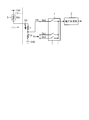
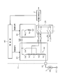
- FIG. 1 is a diagram illustrating a configuration of a voltage measurement system in the first embodiment.
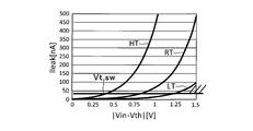
- FIG. 2 is a diagram illustrating an example of off-leakage current characteristics of a multiplexer.
- the voltage measurement system of this embodiment selectively inputs sensor signals output from a plurality of sensors to a voltage measurement unit 2 that is an A / D converter, for example, via a multiplexer 1.
- the signal voltage is measured.
- One of the plurality of sensors is a thermistor 3, and a sensor signal of the thermistor 3 is input to an input terminal Sin 0 of the multiplexer 1.
- the thermistor 3 is connected in series with the driving resistor Rd and the level shift resistor Rl between the power source Vdd and the ground. These are connected in order of the driving resistor Rd, the level shift resistor Rl, and the thermistor 3 from the power supply Vdd side, and constitute a series circuit 6.
- a common connection point of the resistors Rd and Rl is connected to the input terminal Sin0.
- sensor signals from other sensors are input to the other input terminals Sin1, Sin2,.
- the thermistor 3 it is comprised as an internal circuit of IC7, and the thermistor 3 is externally attached to IC7.
- the level shift resistor Rl is inserted to level shift the terminal voltage of the thermistor 3 that divides the power supply voltage. This is because, generally, the thermistor 3 exhibits a negative temperature characteristic. Therefore, when the detected temperature becomes high, the terminal voltage becomes a level near zero. Then, as shown in FIG. 1, the potential difference from the signal voltage Vin of the other sensor becomes large, and a leak current Ileak is generated in the multiplexer 1. In order to reduce the leakage current Ileak, a level shift resistor Rl is inserted to shift the terminal voltage of the thermistor 3 in level.
- the resistance value of the level shift resistor Rl is determined as follows. As shown in FIG. 2, when the terminal voltage of the thermistor 3 is Vth, the leakage current Ileak rises exponentially according to the magnitude of the absolute value
- the voltage value between the input terminals of the multiplexer 1 exceeding the standard set for off-leakage is Vt, sw. Then, the absolute value
- ⁇ Vt, sw the highest voltage is selected from the other signal voltages applied to the input terminal of the multiplexer 1.
- the terminal voltage Vth is expressed by equation (2).
- Vth (Rth + Rl) ⁇ Ith (2)
- the resistance value Rl is determined from the relationship of these equations (1) to (3).
- Vt 3.0V
- Vin 1.0V
- Vt 1.0V
- Vt 1.0V
- Vt 1.0V
- Vt 1.0V
- Vt 1.0V
- Vt 1.0V
- Vt 1.0V
- Vt 1.0V
- Vt 1.0V
- Vt 1.0V
- Vt 1.0V
- Vt 1.0V
- Vt 1.0V
- Vt 1.0V
- Rth 500 ⁇
- Rd 5k ⁇ corresponding to the high temperature region HT.
- Ith 3 / (5.5k + Rl)
- Vth (500 + Rl) ⁇
- Ith 3 ⁇ (500 + Rl) / (5.5k + Rl)
- the power supply and the ground are connected.
- a series circuit 6 including a thermistor 3, a driving resistor Rd, and a level shift resistor Rl. Then, a common connection point between the driving resistor Rd and the level shift resistor Rl is connected to the input terminal Sin0 of the multiplexer 1.
- the same parts as those in the first embodiment are denoted by the same reference numerals, description thereof will be omitted, and different parts will be described.
- the driving resistor Rd, the level shift resistor Rl, and the thermistor 3 are connected in this order from the power supply Vdd side.
- the thermistor 3, the driving resistor Rd, and the level shift resistor Rl are connected in this order from the power supply Vdd side, and these constitute a series circuit 11.
- the common connection point of the resistor Rd and the resistor Rl is connected to the input terminal Sin0 of the multiplexer 1.
- the components other than the thermistor 3 are configured inside the IC 12.
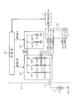
- the resistance value of the driving resistor is switched in accordance with the temperature range detected by the thermistor 3 in order to improve the linearity of the output voltage.
- the configuration of the third embodiment includes a current correction unit for suppressing fluctuations in the power supply voltage that occur when the resistance value is switched.
- the thermistor 3 is connected between the input terminal 22 of the IC 21 and the ground. Between the power supply Vdd and the input terminal 22, there are three switches SWL, SWR, SWH in the IC 21; corresponding driving resistors Rd_LT, Rd_RT, Rd_HT; and level shift resistors Rl_LT, Rl_RT, Rl_HT; Are connected in series. These three series circuits constitute a drive circuit unit 23. Further, a series circuit of two switches SWL_C and SWR_C and corresponding current correction resistors Rc1 and Rc2 are connected between the power supply Vdd and the ground. These two series circuits constitute a current correction unit 24.
- connection points of the resistors Rd_LT, Rd_RT, Rd_HT and the resistors Rl_LT, Rl_RT, Rl_HT are connected to input terminals Sin0A, Sin0B, Sin0C of the multiplexer 25, respectively.
- the output terminal of the multiplexer 25 is connected to the input terminal of the voltage measuring unit 2.
- the voltage measuring unit 2 measures the voltages of the sensor signals Vth1, Vth2, Vth3 of the thermistor 3 selectively input via the multiplexer 25 and other sensor signals Vin1, Vin2,. Input to the control unit 26.
- the control unit 26 switches each switch of the drive circuit unit 23 and the current correction unit 24 according to the voltage data input from the voltage measurement unit 2.
- the resistance value of the thermistor 3 exhibits a negative temperature characteristic that decreases exponentially as the temperature to be detected increases.
- the control unit 26 selectively switches the driving resistors Rd_LT, Rd_RT, and Rd_HT connected to the thermistor 3 in accordance with the temperature zone detected by the thermistor 3. Accordingly, connection switching is also performed for the level shift resistors Rl_LT, Rl_RT, and Rl_HT. For example, -5 ° C or less: Low temperature range LT -5 ° C and below 60 ° C: Medium temperature range RT Greater than 60 ° C: High temperature range HT It is divided into three temperature zones as follows.
- the multiplexer 25 selects the input terminal Sin0C.
- the switch SWR is closed and the resistors Rd_RT and Rl_RT are connected to the thermistor 3, and the multiplexer 25 selects the input terminal Sin0B.
- the switch SWH is closed to connect the resistance elements Rd_HT and Rl_HT to the thermistor 3, and the multiplexer 25 selects the input terminal Sin0A.
- the connection state of the current correction resistors Rc1 and Rc2 in the current correction unit 24 is also switched in order to suppress the fluctuation amount of the power supply current caused by the connection switching.
- the switch SWH In the high temperature region HT, only the switch SWH is closed as described above, but in the intermediate temperature region RT, the switch SWR is closed and the switch SWR_C of the current correction unit 24 is closed, and the resistor Rc2 is connected between the power source and the ground. This suppresses fluctuations in the power supply current before and after switching from the high temperature region HT to the medium temperature region RT. Further, in the low temperature range LT, the switch SWL is closed and the switch SWL_C of the current correction unit 24 is closed, and the resistor Rc1 is connected between the power source and the ground, so that before and after switching from the intermediate temperature range RT to the low temperature range LT. Suppresses fluctuations in the power supply current.
- the power source current is also changed before and after switching from the low temperature range LT to the medium temperature range RT and from the medium temperature range RT to the high temperature range HT. It acts to suppress fluctuations. That is, opening / closing of the switch SWL_C is performed in switching between the RT / LT modes, and opening / closing of the switch SWR_C is performed in switching between the HT / RT modes.
- the three driving resistors Rd_LT, Rd_RT, and Rd_HT are provided so that they can be selectively connected to the thermistor 3.
- the current correction resistors Rc1 and Rc2 that are selectively connected and the terminal voltage Vth of the thermistor 3 are used for driving.
- a control unit 26 that switches the connection states of the current correction resistors Rc1 and Rc2 together when switching the connection states of the resistors Rd_LT, Rd_RT, and Rd_HT.
- the thermistor 3 is connected between the power supply Vdd and the input terminal 32 of the IC 31. That is, as in the second embodiment, the configuration of the third embodiment is applied when one end of the thermistor 3 is connected to the power supply Vdd.
- the drive circuit unit connected between the input terminal 32 and the ground is 23G
- the switch SW_C is connected to the ground side
- the current correction unit connected to the power correction side Rc is 24G.
- the current correction unit 24G has substantially the same configuration as the current correction unit 24 of the third embodiment.
- the configuration of the third embodiment can be applied when one end of the thermistor 3 is connected to the power supply Vdd.
- the detection temperature zone of the thermistor 3 is divided into two, for example, a high temperature region HT and a low temperature region LT with a threshold value of 30 ° C.
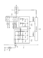
- the drive circuit unit 43 in the IC 41 includes a switch SWL, a drive resistor Rd1, a level shift resistor Rl1, a drive resistor Rd2, a level between the power source Vdd and the input terminal 42 of the IC 41.
- a shift resistor Rl2 is connected in series. These constitute a series circuit 44.
- the common connection point of the resistors Rd1 and Rl1 and the common connection point of the resistors Rd2 and Rl2 are connected to the input terminals Sin0A and Sin0B of the multiplexer 25, respectively.
- a switch SWH is connected between the power supply Vdd and the common connection point of the resistors Rl1 and Rd2.
- the current correction unit 45 includes only a series circuit of the switch SWL_C and the current correction resistor Rc1.
- the control unit 46 closes the switch SWH.
- the upper end of the driving resistor Rd2 is connected to the power supply Vdd.
- the multiplexer 25 selects the input terminal Sin0B and inputs the signal Vth2 that appears at the common connection point of the resistors Rd2 and Rl2.
- the driving resistor Rd1 and the level shift resistor Rl1 positioned on the power supply side with respect to the common connection point become the driving resistors, and the driving resistor Rd2 and the level shift resistor positioned on the ground side with respect to the common connection point.
- Rl2 is a level shift resistor.
- the control unit 46 closes the switch SWL and connects the upper end of the driving resistor Rd1 to the power source Vdd.
- the multiplexer 25 selects the input terminal Sin0A and inputs the signal Vth1 that appears at the common connection point of the resistors Rd1 and Rl1.
- the drive resistor Rd2 and the level shift resistor Rl2 are also used as level shift resistors.
- the control unit 46 closes the switch SWL_C of the current correction unit 45 and connects the current correction resistor Rc1 between the power supply Vdd and the ground.
- the series circuit 44 includes the four resistors Rd1, Rl1, Rd2, and the resistor Rl2.
- the control unit 46 selectively connects the common connection point of the two resistors Rd1 and Rl1 or the resistors Rd2 and Rl2 in the series circuit 44 to the input terminal Sin0A or Sin0B of the multiplexer 25, and more than the common connection point.
- the terminal located on the power supply side is selectively connected to the power supply Vdd.
- the resistance between the power supply Vdd and the input terminal Sin0A or Sin0B can be used as a driving resistor, and the resistance between the input terminal Sin0A or Sin0B and the thermistor 3 can be used as a level shift resistor.
- the thermistor 3 is connected between the power supply Vdd and the input terminal 52 of the IC 51. That is, as in the second embodiment, the configuration of the fifth embodiment is applied when one end of the thermistor 3 is connected to the power supply Vdd.
- the drive circuit unit connected between the input terminal 52 and the ground is 43G
- the switch SWL_C is connected to the ground side
- the current correction unit connected to the current correction resistor Rc1 is the power supply side is 45G.
- the configuration of the fifth embodiment can be applied to a configuration in which one end of the thermistor 3 is connected to the power supply Vdd.
- the third or fourth embodiment may be applied to two temperature ranges as in the fifth or sixth embodiment, or may be applied to four or more temperature ranges.
- the number of resistance elements of the series circuit may be “3” or “5” or more, and may be applied to three or more temperature ranges as in the third or fourth embodiment. good.
Landscapes
- Physics & Mathematics (AREA)
- General Physics & Mathematics (AREA)
- Nonlinear Science (AREA)
- Measuring Temperature Or Quantity Of Heat (AREA)
Priority Applications (1)
| Application Number | Priority Date | Filing Date | Title |
|---|---|---|---|
| US16/300,072 US10837843B2 (en) | 2016-11-09 | 2017-08-29 | Voltage measuring system |
Applications Claiming Priority (2)
| Application Number | Priority Date | Filing Date | Title |
|---|---|---|---|
| JP2016218943A JP6733508B2 (ja) | 2016-11-09 | 2016-11-09 | 電圧測定システム |
| JP2016-218943 | 2016-11-09 |
Publications (1)
| Publication Number | Publication Date |
|---|---|
| WO2018087992A1 true WO2018087992A1 (ja) | 2018-05-17 |
Family
ID=62109209
Family Applications (1)
| Application Number | Title | Priority Date | Filing Date |
|---|---|---|---|
| PCT/JP2017/030926 Ceased WO2018087992A1 (ja) | 2016-11-09 | 2017-08-29 | 電圧測定システム |
Country Status (3)
| Country | Link |
|---|---|
| US (1) | US10837843B2 (enExample) |
| JP (1) | JP6733508B2 (enExample) |
| WO (1) | WO2018087992A1 (enExample) |
Cited By (1)
| Publication number | Priority date | Publication date | Assignee | Title |
|---|---|---|---|---|
| DE102024113307A1 (de) | 2023-05-31 | 2024-12-05 | Steering Solutions Ip Holding Corporation | Teleskopier-entriegelungsmechanismus |
Families Citing this family (4)
| Publication number | Priority date | Publication date | Assignee | Title |
|---|---|---|---|---|
| JP6527627B1 (ja) * | 2018-08-31 | 2019-06-05 | 株式会社バーチャルキャスト | コンテンツ配信サーバ、コンテンツ配信システム、コンテンツ配信方法及びプログラム |
| JP2021006776A (ja) * | 2019-06-28 | 2021-01-21 | 株式会社Subaru | 温度検出装置 |
| US12013293B2 (en) * | 2022-03-24 | 2024-06-18 | Semiconductor Components Industries, Llc | Systems and methods for temperature measurements |
| CN115165134A (zh) * | 2022-03-30 | 2022-10-11 | 北京强度环境研究所 | 一种可切换热敏电阻温度变换器 |
Citations (3)
| Publication number | Priority date | Publication date | Assignee | Title |
|---|---|---|---|---|
| JPH03215723A (ja) * | 1990-01-20 | 1991-09-20 | Mitsubishi Electric Corp | 温度検出装置 |
| JPH0545232A (ja) * | 1991-08-19 | 1993-02-23 | Zexel Corp | 温度検出装置 |
| JP2013504250A (ja) * | 2009-09-04 | 2013-02-04 | ローズマウント インコーポレイテッド | リーク電流を検出及び補正するマルチプレクサ |
Family Cites Families (9)
| Publication number | Priority date | Publication date | Assignee | Title |
|---|---|---|---|---|
| US7322743B2 (en) * | 2005-07-25 | 2008-01-29 | Caterpillar Inc. | Temperature measurement system and method |
| US8197123B2 (en) * | 2007-10-29 | 2012-06-12 | Smiths Medical Asd, Inc. | Thermistor circuit calibration |
| JP5326738B2 (ja) | 2009-03-28 | 2013-10-30 | シンフォニアテクノロジー株式会社 | サーマルヘッド温度測定装置、及びそれを備えたサーマルプリンタ |
| JP2012247218A (ja) | 2011-05-25 | 2012-12-13 | Mitsumi Electric Co Ltd | 温度計測システム |
| JP5981319B2 (ja) | 2012-11-22 | 2016-08-31 | 日立オートモティブシステムズ株式会社 | 吸気温度センサ装置および流量測定装置 |
| JP5776705B2 (ja) * | 2013-02-06 | 2015-09-09 | 株式会社デンソー | 温度検出装置 |
| JP2015145823A (ja) | 2014-02-03 | 2015-08-13 | 株式会社リコー | 温度検出装置 |
| JP2015200633A (ja) | 2014-04-04 | 2015-11-12 | 株式会社デンソー | サーミスタの温度特性補正装置及びサーミスタの温度特性補正方法 |
| JP6583216B2 (ja) * | 2016-11-09 | 2019-10-02 | 株式会社デンソー | サーミスタ駆動回路 |
-
2016
- 2016-11-09 JP JP2016218943A patent/JP6733508B2/ja not_active Expired - Fee Related
-
2017
- 2017-08-29 US US16/300,072 patent/US10837843B2/en not_active Expired - Fee Related
- 2017-08-29 WO PCT/JP2017/030926 patent/WO2018087992A1/ja not_active Ceased
Patent Citations (3)
| Publication number | Priority date | Publication date | Assignee | Title |
|---|---|---|---|---|
| JPH03215723A (ja) * | 1990-01-20 | 1991-09-20 | Mitsubishi Electric Corp | 温度検出装置 |
| JPH0545232A (ja) * | 1991-08-19 | 1993-02-23 | Zexel Corp | 温度検出装置 |
| JP2013504250A (ja) * | 2009-09-04 | 2013-02-04 | ローズマウント インコーポレイテッド | リーク電流を検出及び補正するマルチプレクサ |
Cited By (1)
| Publication number | Priority date | Publication date | Assignee | Title |
|---|---|---|---|---|
| DE102024113307A1 (de) | 2023-05-31 | 2024-12-05 | Steering Solutions Ip Holding Corporation | Teleskopier-entriegelungsmechanismus |
Also Published As
| Publication number | Publication date |
|---|---|
| JP2018077133A (ja) | 2018-05-17 |
| US10837843B2 (en) | 2020-11-17 |
| US20190154519A1 (en) | 2019-05-23 |
| JP6733508B2 (ja) | 2020-08-05 |
Similar Documents
| Publication | Publication Date | Title |
|---|---|---|
| WO2018087992A1 (ja) | 電圧測定システム | |
| JP6262411B2 (ja) | 電力変換装置、および、半導体装置 | |
| US20190242759A1 (en) | Thermistor drive circuit | |
| KR101918338B1 (ko) | 센서 장치 | |
| JP7204447B2 (ja) | 積分型の電流電圧変換回路、電流測定装置および抵抗測定装置 | |
| TW201040557A (en) | Detection circuit and sensor device | |
| JP5839319B2 (ja) | 電流/電圧変換回路 | |
| US8816668B2 (en) | Semiconductor circuit for outputting reference voltages | |
| US9618571B2 (en) | Detection circuit for relative error voltage | |
| JP2013152181A (ja) | 電流検出回路 | |
| JP2005217870A (ja) | A/d変換装置 | |
| JP2011250609A (ja) | 半導体装置 | |
| US7772853B2 (en) | Semiconductor device | |
| JP5729254B2 (ja) | ヒシテリシス装置 | |
| JP6688648B2 (ja) | 電流検出回路 | |
| WO2018179372A1 (ja) | アナログ入力ユニット及び基準電圧安定化回路 | |
| JP5608328B2 (ja) | 定電流回路、及び試験装置 | |
| JP2010200449A (ja) | 電圧制限回路 | |
| CN103105885B (zh) | 高压基准电压产生电路 | |
| KR101790288B1 (ko) | 차동 입력 레벨 쉬프터 | |
| JP2020101572A (ja) | 電流検出回路 | |
| JP2012068074A (ja) | 電圧範囲検出装置 | |
| CN103592603A (zh) | 电池测量电路、系统及方法 | |
| US10620656B2 (en) | Operating voltage switching device with current mirror | |
| JP2002076804A (ja) | 温度調整器の入力回路 |
Legal Events
| Date | Code | Title | Description |
|---|---|---|---|
| 121 | Ep: the epo has been informed by wipo that ep was designated in this application |
Ref document number: 17869252 Country of ref document: EP Kind code of ref document: A1 |
|
| NENP | Non-entry into the national phase |
Ref country code: DE |
|
| 122 | Ep: pct application non-entry in european phase |
Ref document number: 17869252 Country of ref document: EP Kind code of ref document: A1 |