WO2018084146A1 - 作業機械用周辺監視システム - Google Patents
作業機械用周辺監視システム Download PDFInfo
- Publication number
- WO2018084146A1 WO2018084146A1 PCT/JP2017/039339 JP2017039339W WO2018084146A1 WO 2018084146 A1 WO2018084146 A1 WO 2018084146A1 JP 2017039339 W JP2017039339 W JP 2017039339W WO 2018084146 A1 WO2018084146 A1 WO 2018084146A1
- Authority
- WO
- WIPO (PCT)
- Prior art keywords
- image
- person
- display
- work machine
- monitoring
- Prior art date
Links
- 238000012544 monitoring process Methods 0.000 title claims abstract description 308
- 238000001514 detection method Methods 0.000 claims abstract description 97
- 230000002093 peripheral effect Effects 0.000 claims description 84
- 238000003384 imaging method Methods 0.000 claims description 43
- 238000006243 chemical reaction Methods 0.000 description 21
- 239000010720 hydraulic oil Substances 0.000 description 12
- 239000000446 fuel Substances 0.000 description 11
- 238000010586 diagram Methods 0.000 description 10
- 238000000034 method Methods 0.000 description 10
- 238000012545 processing Methods 0.000 description 10
- 230000002159 abnormal effect Effects 0.000 description 9
- 230000009471 action Effects 0.000 description 9
- 239000000498 cooling water Substances 0.000 description 8
- 230000008569 process Effects 0.000 description 8
- 239000002826 coolant Substances 0.000 description 7
- 230000009467 reduction Effects 0.000 description 7
- 230000006870 function Effects 0.000 description 5
- 239000011435 rock Substances 0.000 description 3
- 240000004050 Pentaglottis sempervirens Species 0.000 description 2
- 235000004522 Pentaglottis sempervirens Nutrition 0.000 description 2
- 241000270666 Testudines Species 0.000 description 2
- 238000013459 approach Methods 0.000 description 2
- 230000006399 behavior Effects 0.000 description 2
- 230000008859 change Effects 0.000 description 2
- 239000002828 fuel tank Substances 0.000 description 2
- 238000003825 pressing Methods 0.000 description 2
- 230000005856 abnormality Effects 0.000 description 1
- 239000010426 asphalt Substances 0.000 description 1
- 238000012790 confirmation Methods 0.000 description 1
- 239000004035 construction material Substances 0.000 description 1
- 230000008602 contraction Effects 0.000 description 1
- 238000006073 displacement reaction Methods 0.000 description 1
- 230000004927 fusion Effects 0.000 description 1
- 238000010801 machine learning Methods 0.000 description 1
- 230000007246 mechanism Effects 0.000 description 1
- 239000003921 oil Substances 0.000 description 1
- 230000003287 optical effect Effects 0.000 description 1
- 238000003672 processing method Methods 0.000 description 1
- XLYOFNOQVPJJNP-UHFFFAOYSA-N water Substances O XLYOFNOQVPJJNP-UHFFFAOYSA-N 0.000 description 1
Images


Classifications
-
- H—ELECTRICITY
- H04—ELECTRIC COMMUNICATION TECHNIQUE
- H04N—PICTORIAL COMMUNICATION, e.g. TELEVISION
- H04N7/00—Television systems
- H04N7/18—Closed-circuit television [CCTV] systems, i.e. systems in which the video signal is not broadcast
-
- B—PERFORMING OPERATIONS; TRANSPORTING
- B60—VEHICLES IN GENERAL
- B60R—VEHICLES, VEHICLE FITTINGS, OR VEHICLE PARTS, NOT OTHERWISE PROVIDED FOR
- B60R1/00—Optical viewing arrangements; Real-time viewing arrangements for drivers or passengers using optical image capturing systems, e.g. cameras or video systems specially adapted for use in or on vehicles
- B60R1/20—Real-time viewing arrangements for drivers or passengers using optical image capturing systems, e.g. cameras or video systems specially adapted for use in or on vehicles
- B60R1/22—Real-time viewing arrangements for drivers or passengers using optical image capturing systems, e.g. cameras or video systems specially adapted for use in or on vehicles for viewing an area outside the vehicle, e.g. the exterior of the vehicle
- B60R1/23—Real-time viewing arrangements for drivers or passengers using optical image capturing systems, e.g. cameras or video systems specially adapted for use in or on vehicles for viewing an area outside the vehicle, e.g. the exterior of the vehicle with a predetermined field of view
- B60R1/27—Real-time viewing arrangements for drivers or passengers using optical image capturing systems, e.g. cameras or video systems specially adapted for use in or on vehicles for viewing an area outside the vehicle, e.g. the exterior of the vehicle with a predetermined field of view providing all-round vision, e.g. using omnidirectional cameras
-
- B—PERFORMING OPERATIONS; TRANSPORTING
- B60—VEHICLES IN GENERAL
- B60K—ARRANGEMENT OR MOUNTING OF PROPULSION UNITS OR OF TRANSMISSIONS IN VEHICLES; ARRANGEMENT OR MOUNTING OF PLURAL DIVERSE PRIME-MOVERS IN VEHICLES; AUXILIARY DRIVES FOR VEHICLES; INSTRUMENTATION OR DASHBOARDS FOR VEHICLES; ARRANGEMENTS IN CONNECTION WITH COOLING, AIR INTAKE, GAS EXHAUST OR FUEL SUPPLY OF PROPULSION UNITS IN VEHICLES
- B60K35/00—Arrangement of adaptations of instruments
-
- B60K35/81—
-
- B—PERFORMING OPERATIONS; TRANSPORTING
- B60—VEHICLES IN GENERAL
- B60R—VEHICLES, VEHICLE FITTINGS, OR VEHICLE PARTS, NOT OTHERWISE PROVIDED FOR
- B60R1/00—Optical viewing arrangements; Real-time viewing arrangements for drivers or passengers using optical image capturing systems, e.g. cameras or video systems specially adapted for use in or on vehicles
-
- B—PERFORMING OPERATIONS; TRANSPORTING
- B66—HOISTING; LIFTING; HAULING
- B66F—HOISTING, LIFTING, HAULING OR PUSHING, NOT OTHERWISE PROVIDED FOR, e.g. DEVICES WHICH APPLY A LIFTING OR PUSHING FORCE DIRECTLY TO THE SURFACE OF A LOAD
- B66F17/00—Safety devices, e.g. for limiting or indicating lifting force
- B66F17/003—Safety devices, e.g. for limiting or indicating lifting force for fork-lift trucks
-
- E—FIXED CONSTRUCTIONS
- E02—HYDRAULIC ENGINEERING; FOUNDATIONS; SOIL SHIFTING
- E02F—DREDGING; SOIL-SHIFTING
- E02F9/00—Component parts of dredgers or soil-shifting machines, not restricted to one of the kinds covered by groups E02F3/00 - E02F7/00
- E02F9/24—Safety devices, e.g. for preventing overload
-
- E—FIXED CONSTRUCTIONS
- E02—HYDRAULIC ENGINEERING; FOUNDATIONS; SOIL SHIFTING
- E02F—DREDGING; SOIL-SHIFTING
- E02F9/00—Component parts of dredgers or soil-shifting machines, not restricted to one of the kinds covered by groups E02F3/00 - E02F7/00
- E02F9/26—Indicating devices
-
- E—FIXED CONSTRUCTIONS
- E02—HYDRAULIC ENGINEERING; FOUNDATIONS; SOIL SHIFTING
- E02F—DREDGING; SOIL-SHIFTING
- E02F9/00—Component parts of dredgers or soil-shifting machines, not restricted to one of the kinds covered by groups E02F3/00 - E02F7/00
- E02F9/26—Indicating devices
- E02F9/261—Surveying the work-site to be treated
-
- G—PHYSICS
- G06—COMPUTING; CALCULATING OR COUNTING
- G06V—IMAGE OR VIDEO RECOGNITION OR UNDERSTANDING
- G06V20/00—Scenes; Scene-specific elements
- G06V20/50—Context or environment of the image
- G06V20/56—Context or environment of the image exterior to a vehicle by using sensors mounted on the vehicle
- G06V20/58—Recognition of moving objects or obstacles, e.g. vehicles or pedestrians; Recognition of traffic objects, e.g. traffic signs, traffic lights or roads
-
- G—PHYSICS
- G06—COMPUTING; CALCULATING OR COUNTING
- G06V—IMAGE OR VIDEO RECOGNITION OR UNDERSTANDING
- G06V40/00—Recognition of biometric, human-related or animal-related patterns in image or video data
- G06V40/10—Human or animal bodies, e.g. vehicle occupants or pedestrians; Body parts, e.g. hands
- G06V40/103—Static body considered as a whole, e.g. static pedestrian or occupant recognition
-
- H—ELECTRICITY
- H04—ELECTRIC COMMUNICATION TECHNIQUE
- H04N—PICTORIAL COMMUNICATION, e.g. TELEVISION
- H04N5/00—Details of television systems
- H04N5/222—Studio circuitry; Studio devices; Studio equipment
- H04N5/262—Studio circuits, e.g. for mixing, switching-over, change of character of image, other special effects ; Cameras specially adapted for the electronic generation of special effects
- H04N5/2628—Alteration of picture size, shape, position or orientation, e.g. zooming, rotation, rolling, perspective, translation
-
- H—ELECTRICITY
- H04—ELECTRIC COMMUNICATION TECHNIQUE
- H04N—PICTORIAL COMMUNICATION, e.g. TELEVISION
- H04N7/00—Television systems
- H04N7/18—Closed-circuit television [CCTV] systems, i.e. systems in which the video signal is not broadcast
- H04N7/183—Closed-circuit television [CCTV] systems, i.e. systems in which the video signal is not broadcast for receiving images from a single remote source
-
- B—PERFORMING OPERATIONS; TRANSPORTING
- B60—VEHICLES IN GENERAL
- B60R—VEHICLES, VEHICLE FITTINGS, OR VEHICLE PARTS, NOT OTHERWISE PROVIDED FOR
- B60R2300/00—Details of viewing arrangements using cameras and displays, specially adapted for use in a vehicle
- B60R2300/30—Details of viewing arrangements using cameras and displays, specially adapted for use in a vehicle characterised by the type of image processing
- B60R2300/306—Details of viewing arrangements using cameras and displays, specially adapted for use in a vehicle characterised by the type of image processing using a re-scaling of images
-
- B—PERFORMING OPERATIONS; TRANSPORTING
- B60—VEHICLES IN GENERAL
- B60R—VEHICLES, VEHICLE FITTINGS, OR VEHICLE PARTS, NOT OTHERWISE PROVIDED FOR
- B60R2300/00—Details of viewing arrangements using cameras and displays, specially adapted for use in a vehicle
- B60R2300/70—Details of viewing arrangements using cameras and displays, specially adapted for use in a vehicle characterised by an event-triggered choice to display a specific image among a selection of captured images
-
- B—PERFORMING OPERATIONS; TRANSPORTING
- B60—VEHICLES IN GENERAL
- B60R—VEHICLES, VEHICLE FITTINGS, OR VEHICLE PARTS, NOT OTHERWISE PROVIDED FOR
- B60R2300/00—Details of viewing arrangements using cameras and displays, specially adapted for use in a vehicle
- B60R2300/80—Details of viewing arrangements using cameras and displays, specially adapted for use in a vehicle characterised by the intended use of the viewing arrangement
- B60R2300/8033—Details of viewing arrangements using cameras and displays, specially adapted for use in a vehicle characterised by the intended use of the viewing arrangement for pedestrian protection
Definitions
- the present invention relates to a peripheral monitoring system for work machines.
- Perimeter monitoring for displaying a monitoring image for example, a bird's-eye view viewed from directly above the work machine
- a monitoring image for example, a bird's-eye view viewed from directly above the work machine
- an imaging device camera
- An apparatus is known (for example, refer to Patent Document 1).
- Patent Document 1 when a person is detected in a predetermined area around the work machine, the monitoring image is enlarged from the wide area display to the vicinity display.
- Patent Document 1 the monitoring image is enlarged from the wide area display to the near area display around the image that simply represents the work machine. For this reason, the operator may not be able to immediately grasp the state of the detected person displayed around the image imitating the central work machine in the monitoring image.
- an object of the present invention is to provide a work machine periphery monitoring system that allows an operator to quickly grasp the state of a detected person when a person is detected around the work machine. To do.
- a display device provided in the cabin of the work machine; An imaging device for imaging the periphery of the work machine; An image generating unit that generates a peripheral image of the work machine based on a captured image of the imaging device; For monitoring including a work machine image schematically representing the work machine, and the surrounding image arranged around the work machine image in accordance with a relative positional relationship between the work machine and an imaging range of the imaging device
- a display control unit for displaying an image on the display device;
- a human detection unit for detecting a person in a predetermined area around the work machine, The display control unit is a partial region of the peripheral image in the monitoring image and is included in the peripheral image rather than the work machine image when a person is detected in the predetermined region by the human detection unit. Centered on a position close to the person, the display device displays an enlarged monitoring image in which a partial area including the person is enlarged,
- a work machine peripheral monitoring system is provided.
- FIG. 1 is a diagram illustrating an example of a work machine on which the periphery monitoring system 100 according to the present embodiment is mounted, and more specifically, a side view of an excavator.
- the periphery monitoring system 100 may be mounted on a work machine other than an excavator, for example, a wheel loader, an asphalt finisher, or the like.
- the shovel according to the present embodiment includes a lower traveling body 1, an upper revolving body 3 that is mounted on the lower traveling body 1 so as to be able to swivel via a turning mechanism 2, a boom 4, an arm 5, and a bucket 6 as working devices. And a cabin 10 on which the operator is boarded.
- the lower traveling body 1 includes, for example, a pair of left and right crawlers, and each crawler is hydraulically driven by a traveling hydraulic motor (not shown) to cause the excavator to travel.
- the upper swing body 3 rotates with respect to the lower traveling body 1 by being driven by a swing hydraulic motor, an electric motor (both not shown) or the like.
- the boom 4 is pivotally attached to the center of the front part of the upper swing body 3 so that the boom 4 can be raised and lowered.
- An arm 5 is pivotally attached to the tip of the boom 4 and a bucket 6 is vertically attached to the tip of the arm 5. It is pivotally attached so that it can rotate.
- the boom 4, the arm 5, and the bucket 6 are hydraulically driven by a boom cylinder 7, an arm cylinder 8, and a bucket cylinder 9, respectively.
- the cabin 10 is a cockpit where an operator boardes, and is mounted on the front left side of the upper swing body 3.
- the excavator includes a controller 30, an imaging device 40, an object detection sensor 42, and a display device 50.
- the controller 30 is a control device that performs drive control of the excavator.
- the controller 30 is mounted in the cabin 10.
- the imaging device 40 is attached to the upper part of the upper swing body 3 and images the periphery of the excavator.
- the imaging device 40 includes a rear camera 40B, a left side camera 40L, and a right side camera 40R.
- the rear camera 40B is attached to the upper part of the rear end of the upper swing body 3, and images the rear of the upper swing body 3.
- the left side camera 40L is attached to the upper left end of the upper swing body 3 and images the left side of the upper swing body 3.
- the right side camera 40R is attached to the upper right end of the upper swing body 3 and images the right side of the upper swing body 3.
- the object detection sensor 42 is attached to the outer surface or the like of the upper swing body 3 and detects an object (obstacle) around the excavator, specifically, the rear, left side, and right side of the upper swing body 3. To do.
- the object that can be detected by the object detection sensor 42 may include a person.
- the object detection sensor 42 detects a sensor behind the upper swing body 3, a sensor that detects an object on the left side of the upper swing body 3, and an object on the right side of the upper swing body 3. It may be an embodiment including three sensors to be detected.
- the object detection sensor 42 for example, an ultrasonic sensor or a millimeter wave that can detect an object by outputting a detection wave or a laser to the periphery of the excavator (upper rotating body 3) and receiving the reflected wave or reflected light. Radar, LIDAR (Light Detection and Ranging), etc. can be included.
- the object detection sensor 42 can determine whether the detected object is a person or an object other than a person based on the intensity of a reflected wave or reflected light.
- the object detection sensor 42 may be a stereo camera, for example.
- the display device 50 is provided around the cockpit in the cabin 10 and displays various image information notified to the operator under the control of the controller 30 (a display control unit 302 described later).
- FIG. 2A is a block diagram showing an example of the configuration of the periphery monitoring system 100 according to the present embodiment.
- the periphery monitoring system 100 includes a controller 30, an imaging device 40, and a display device 50.
- the controller 30 performs main control processing in the periphery monitoring system 100.
- the controller 30 may be realized by arbitrary hardware, software, or a combination thereof.
- the controller 30 is mainly configured by a microcomputer including a CPU, RAM, ROM, I / O, and the like.
- the controller 30 includes a human detection unit 301 and a display control unit 302 as functional units realized by executing various programs stored in the ROM on the CPU.
- the imaging device 40 includes the rear camera 40B, the left side camera 40L, and the right side camera 40R as described above.
- the rear camera 40B, the left side camera 40L, and the right side camera 40R are mounted on the upper part of the upper revolving unit 3 so that the optical axis is obliquely downward, and includes an image in the vertical direction including the ground in the vicinity of the shovel to the far side of the shovel. It has a range (angle of view).
- the rear camera 40B, the left side camera 40L, and the right side camera 40R output a captured image to the controller 30 at predetermined intervals (for example, 1/30 seconds) during operation of the excavator, and the captured image is captured by the controller 30. It is.
- the object detection sensor 42 outputs the detection results of the periphery of the upper swing body 3 (specifically, the back, left side, and right side detection results of the upper swing body 3 to the controller 30 at predetermined intervals during the operation of the shovel.
- the detection result is captured by the controller 30.
- the display device 50 displays a captured image (through image) of the imaging device 40, a peripheral image (for example, a viewpoint conversion image described later) generated by the controller 30 (display control unit 302) based on the captured image of the imaging device 40, and the like. To do.
- the person detection unit 301 detects a person within a predetermined area around the shovel, for example, a person within a predetermined distance D1 (for example, 5 meters) from the shovel, based on the captured image captured by the imaging device 40.
- the human detection unit 301 recognizes a person in the captured image by arbitrarily applying various known image processing methods, machine learning-based classifiers, and the like, and recognizes the actual position of the recognized person (recognized from the shovel).
- the distance D to the person who has done this can be specified.
- the human detection unit 301 is based on the detection result of the object detection sensor 42 and determines a predetermined area around the shovel. A person in the area may be detected. At this time, the human detection unit 301 can determine whether or not the detected object is a person based on characteristics such as the intensity or pattern of the reflected wave or reflected light included in the detection result of the object detection sensor 42. it can. The human detection unit 301 may detect a person who is a monitoring target based on both a captured image captured by the imaging device 40 and a detection result by the object detection sensor 42 by so-called sensor fusion.
- the display control unit 302 displays various information images on the display device 50.
- the display control unit 302 generates a peripheral image based on the captured image of the imaging device 40 and causes the display device 50 to display the peripheral image.
- the display control unit 302 performs a known viewpoint conversion process based on the captured images of the rear camera 40B, the left camera 40L, and the right camera 40R as the peripheral images, thereby generating a viewpoint converted image (virtual viewpoint).
- the image viewed from the above is generated and displayed on the display device 50.
- the display control unit 302 clearly shows the relative positional relationship with respect to the shovel of the imaging range of the imaging device 40 that appears in the peripheral image.
- An example of a machine image is also displayed on the display device 50. That is, the display control unit 302 generates and displays a monitoring image including a shovel image and a peripheral image arranged around the shovel image in accordance with the relative positional relationship between the shovel and the imaging range of the imaging device 40. It is displayed on the device 50.
- the monitoring image displayed on the display device 50 will be described together with the details of the display device 50 with reference to FIG. 3.
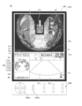
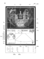
- FIG. 3 is a diagram illustrating an example of a monitoring image displayed on the display device 50.
- the display device 50 includes a display unit 50 ⁇ / b> A on which various information images are displayed and a hardware operation that operates an operation target (for example, an operation button icon or a cursor) displayed on the various information images. Part 50B.
- an operation target for example, an operation button icon or a cursor
- the display unit 50A displays not only the monitoring image MP but also the driving information image IP that presents various information related to the excavator driving. Specifically, the monitoring image MP is displayed on the upper half of the display unit 50A, and the driving information image IP is displayed on the lower half.
- the driving information image IP includes a date / time display area IPa, a travel mode display area IPb, an end attachment display area IPc, an engine control state display area IPe, an engine operating time display area IPf, a cooling water temperature display area IPg, a remaining fuel amount display area IPh, A rotation speed mode display area IPi, a hydraulic oil temperature display area IPk, a camera image display area IPm, an alarm display area IPp, and a direction display icon IPx are included.
- the date / time display area IPa is an area for displaying an image of the current date and time.
- digital display is adopted, the date is February 19, 2013, and the time is 23:59.
- the traveling mode display area IPb is an area for displaying an image of the current traveling mode.
- the traveling mode represents a set state of the traveling hydraulic motor using the variable displacement pump. Specifically, the traveling mode has a low speed mode and a high speed mode.
- the low-speed mode is displayed with a mark imitating “turtle”, and the high-speed mode is displayed with a mark imitating “ ⁇ ”.
- a mark representing a “turtle” is displayed, and the operator can recognize that the low speed mode is set.
- the end attachment display area IPc is an area for displaying an image representing the currently attached end attachment.
- the end attachment attached to the shovel includes various end attachments such as a rock drill, grapple, and lifting magnet in addition to the bucket 6.
- the end attachment display area IPc displays, for example, marks that represent these end attachments. In this example, a mark representing a rock drill is displayed, and the operator can recognize that the rock drill is attached as an end attachment.
- Engine control state display area IPe is an area for displaying an image of the engine control state.
- the operator can recognize that “automatic deceleration / automatic stop mode” is selected as the engine control state.
- the “automatic deceleration / automatic stop mode” means a control state in which the engine speed is automatically reduced and the engine is automatically stopped according to the duration of the state where the engine load is low.
- the engine control state includes “automatic deceleration mode”, “automatic stop mode”, “manual deceleration mode”, and the like.
- the engine operating time display area IPf is an area for displaying an image of the accumulated operating time of the engine. In this example, a value using the unit “hr (hour)” is displayed.
- the cooling water temperature display area IPg is an area for displaying an image of the current temperature state of the engine cooling water.
- a bar graph representing the temperature state of the engine coolant is displayed.
- the engine coolant temperature is displayed based on data output from a water temperature sensor attached to the engine.
- the cooling water temperature display area IPg includes an abnormal range display IPg1, a caution range display IPg2, a normal range display IPg3, a segment display IPg4, and an icon display IPg5.
- the abnormal range display IPg1, the caution range display IPg2, and the normal range display IPg3 are displays for notifying the operator that the temperature of the engine coolant is in an abnormally high temperature state, a state requiring attention, and a normal state, respectively.
- the segment display IPg4 is a display for notifying the operator of the temperature level of the engine coolant.
- the icon display IPg5 is an icon such as a symbol figure indicating that the abnormal range display IPg1, the caution range display IPg2, the normal range display IPg3, and the segment display IPg4 are displays related to the engine coolant temperature.
- the icon display IPg5 may be character information indicating that the display is related to the temperature of the engine coolant.
- the segment display IPg4 is composed of eight segments whose lighting / extinguishing states are individually controlled, and the number of lighting segments increases as the cooling water temperature increases. In this example, four segments are lit.
- the segment display IPg4 forms a part (arc) of a predetermined circle, and is displayed so that the length of the arc expands and contracts according to the vertical movement of the engine coolant temperature.
- the temperature range represented by each segment is the same, but the temperature range may be changed for each segment.
- the abnormal range display IPg1, the caution range display IPg2, and the normal range display IPg3 are arcuate figures arranged side by side along the expansion / contraction direction (circumferential direction of a predetermined circle) of the segment display IPg4. It is displayed in red, yellow and green.
- the segment display IPg4 the first (lowest) to sixth segments belong to the normal range, the seventh segment belongs to the caution range, and the eighth (highest) segment belongs to the abnormal range.
- the abnormal range display IPg1, the caution range display IPg2, and the normal range display IPg3 are displayed as arcuate figures, but characters, symbols representing the abnormal level, the caution level, and the normal level are displayed. Etc. may be displayed at each boundary portion.
- the above-described configuration including the abnormal range display, the caution range display, the normal range display, the segment display, and the icon display can be similarly adopted in the remaining fuel amount display area IPh and the hydraulic oil temperature display area IPk.
- the remaining fuel amount display area IPh instead of displaying arc-shaped figures representing the abnormal range, the caution range, and the normal range, the letter “F” or black circle (filled) indicating “Full (full tank)” is displayed. (Circle)), the letter “E” representing “Empty (empty state)”, a white circle (unfilled circle), or the like may be displayed at each boundary portion.
- Fuel remaining amount display area IPh is an area for displaying an image of the remaining amount of fuel stored in the fuel tank.
- a bar graph representing the current remaining fuel level is displayed.
- the remaining amount of fuel in the remaining fuel amount display area IPh is displayed based on data output by the remaining fuel amount sensor in the fuel tank.
- the rotation speed mode display area IPi is an area for displaying an image of the current rotation speed mode.
- the rotation speed mode includes, for example, the above-described four modes of SP mode, H mode, A mode, and idling mode.
- the symbol “SP” representing the SP mode is displayed.
- the hydraulic oil temperature display area IPk is an area for displaying an image of the temperature state of the hydraulic oil in the hydraulic oil tank. In this example, a bar graph representing the temperature state of the hydraulic oil is displayed. The temperature of the hydraulic oil in the hydraulic oil temperature display area IPk is displayed based on data output from the oil temperature sensor in the hydraulic oil tank.
- a needle display may be employed instead of the bar graph display.
- the camera image display area IPm is an area for displaying at least one captured image (through image) of the rear camera 40B, the left camera 40L, and the right camera 40R as it is. Thereby, the operator can visually recognize the captured image (through image) captured by the imaging device 40 in addition to the monitoring image MP in the driving information image IP.
- a captured image that is always captured by the rear camera 40B may be displayed while the excavator is operating.
- the captured image (through image) of the rear camera 40B in the camera image display area IPm is preferably displayed as a mirror image.
- the camera image display area IPm occupies an area of about two-thirds on the right side of the driving information image IP.
- the remaining fuel amount display area IPh and the like are displayed on the side close to the driver's seat (operator), and the camera image display area IPm on the side far from the driver's seat (operator). This is because the overall visibility is improved.
- the size and arrangement of each display area in the driving information image IP may be changed as necessary.
- the captured image displayed in the camera image display area IPm is switched from the imaging device 40 that is the imaging source of the displayed captured image according to a touch operation or the like on the touch panel display unit 50A or an operation on the operation unit 50B.
- the captured image may be enlarged or reduced.
- the operator performs an operation of designating the left / right direction with the cross button 50Ba of the operation unit 50B, whereby the imaging device 40 (rear camera 40B) that is the imaging source of the captured image (through image) displayed in the camera image display area IPm.
- the left camera 40L and the right camera 40R) can be switched.
- the operator can enlarge or reduce the captured image by pressing each of the button for designating the upward direction and the button for designating the downward direction of the enlargement / reduction button 50Bb. Good.
- the operator can specify a position by touching an arbitrary position of the camera image display area IPm on the touch panel type display unit 50A, and can perform enlargement / reduction around the specified position.
- the operator may move the cursor with the cross button 50Ba so that the operator can perform enlargement / reduction about the cursor position.
- the alarm display area IPp is an area for displaying an alarm.
- a warning message indicating that an electrical system abnormality has occurred is displayed superimposed on the through image.
- an alarm is displayed in the alarm display area IPp to warn that if a lever operation is performed without the captured image captured by the rear camera 40B being displayed in the camera image display area IPm.
- the In the alarm display area IPp when there is no alarm to be displayed, the through image is displayed as it is.
- the orientation display icon IPx is an icon that represents a relative relationship between the orientation of the imaging device 40 that captured the captured image (through image) displayed in the driving information image IP and the orientation of the excavator (attachment of the upper swing body 3). .
- an orientation display icon IPx indicating that the imaging device 40 that captures the camera image displayed in the camera image display area IPm is the rear camera 40B is displayed in the lower right corner of the camera image display area IPm.
- the orientation display icon IPx may be displayed at a position other than the lower right corner, such as the lower center, lower left corner, upper right corner, upper left corner, etc. of the camera image display area IPm, and is displayed outside the camera image display area IPm. Also good.
- the driving information image IP may omit a part of the above-described display areas IPa to IPk, or may include display areas other than those described above.
- the operation information image IP may include an exhaust gas filter state display area for displaying a clogging degree of an exhaust gas filter (for example, a diesel particulate filter (DPF: Diesel Particulate Filter) or the like).
- the exhaust gas filter state display area may display a bar graph indicating the ratio of the current usage time to the allowable maximum usage time of the exhaust gas filter.
- the display of the temperature state of the hydraulic oil may be omitted, and the display of the temperature state of the hydraulic oil and the temperature state of the cooling water may be omitted.
- the lower part of the camera image display area IPm includes a cover image IPq as a vehicle body image that is an image of the upper edge of the rear end of the cover 3a of the upper swing body 3.
- the display device 50 allows the operator to more easily grasp the sense of distance between the object displayed in the camera image display area IPm and the excavator.
- the orientation display icon IPx is displayed superimposed on the cover image IPq. This is because the orientation color of the orientation display icon IPx is always the same so as to improve the visibility. Another reason is to prevent the display icon IPx from hiding the part of the camera image that the user wants to see. However, the orientation display icon IPx may be displayed outside the camera image display area IPm.
- the shovel image CG and the shovel image are displayed in the upper half of the horizontally long rectangular area (for example, a screen with an aspect ratio of 4: 3) in the display unit 50A of the display device 50.
- a monitoring image MP including a peripheral image EP arranged around the CG is displayed. Accordingly, the operator can appropriately grasp the positional relationship between the object including the person shown in the peripheral image EP and the excavator.
- the peripheral image EP in this example is a viewpoint conversion image that combines a road surface image of the excavator periphery viewed from directly above and a horizontal image that is arranged around the road surface image and viewed in the horizontal direction of the excavator periphery.
- Peripheral images are obtained by projecting captured images of the rear camera 40B, the left camera 40L, and the right camera 40R onto a spatial model, and then projecting the projection image projected onto the spatial model into another two images. It is obtained by reprojecting on a dimensional plane.
- the space model is a projection target of the captured image in the virtual space, and is configured by one or a plurality of planes or curved surfaces including a plane or a curved surface other than the plane on which the captured image is located.
- the peripheral image in the present embodiment is a viewpoint conversion image obtained by combining the road surface image and the horizontal image.
- a line segment L representing a position where the distance D from the excavator is constant may be superimposed and displayed on the monitoring image.
- the line segment L represents the position of the predetermined distance D2 whose distance from the excavator is smaller than the predetermined distance D1, for example.
- the monitoring image MP is enlarged or monitored according to a touch operation on the touch panel type display unit 50A or an operation on the operation unit 50B, like the camera image display area IPm of the driving information image IP described above. Reduction may be performed.
- the operator can enlarge or reduce the monitoring image by pressing each of the button for designating the upward direction and the button for designating the downward direction of the enlargement / reduction button 50Bb. It's okay.
- the operator can designate a position by touching an arbitrary position of the monitoring image MP on the touch panel display unit 50A, and can perform enlargement / reduction around the designated position.
- the operator may move the cursor with the cross button 50Ba so that the operator can perform enlargement / reduction about the cursor position.
- the display control unit 302 changes the display mode of the monitoring image so that the detected person can be easily seen by the operator. Specifically, when a person is detected in a predetermined area around the shovel by the person detection unit 301, the display control unit 302 displays the monitoring image, and the position of the detected person in the monitoring image is The display mode is changed to emphasize (emphasize) more than other positions.
- the display control unit 302 enlarges a partial area of a peripheral image including the detected person (hereinafter referred to as “enlargement”).
- a monitor image ”) and generated on the display device 50 is referred to as “enlargement”.
- the monitoring image when no person is detected in the predetermined area around the shovel by the human detection unit 301 is referred to as a “normal monitoring image”.
- the display control unit 302 is a partial region of the peripheral image in the normal monitoring image, and includes the person who is centered on a position closer to the detected person included in the peripheral image than the shovel image.
- An enlarged monitoring image in which the partial area is enlarged is generated.
- the display control unit 302 generates an enlarged monitoring image in which the excavator image is enlarged in accordance with a partial region of the peripheral image. Accordingly, the display control unit 302 arranges the monitoring image with a position close to the detected person as a center, and enlarges a partial area including the detected person's position, thereby detecting the detected person. It is possible to cause the display device 50 to display a monitoring image in a display mode in which the position of is more important than other positions.
- the display control unit 302 may generate an enlarged monitoring image by cutting out and enlarging a partial area of the normal monitoring image. Further, the display control unit 302 generates a peripheral image (viewpoint conversion image) corresponding to the partial area based on the captured image of the imaging device 40, and generates an enlarged monitoring image by combining with the shovel image. Also good.
- the display control unit 302 may change the specification for changing the display mode of the monitoring image according to the distance D between the person and the shovel detected by the human detection unit 301.
- the display control unit 302 may increase the enlargement ratio of the enlargement monitoring image with respect to the normal monitoring image as the distance D between the person detected by the person detection unit 301 and the shovel becomes smaller.
- the display control unit 302 determines that the distance D is less than or equal to a predetermined distance D2 (D1> D2) when the distance D between the person and the shovel detected by the human detection unit 301 within a predetermined region around the shovel.
- the enlargement ratio may be larger than when the distance is not less than the predetermined distance D2.
- the enlarged monitoring image may include a larger area of the peripheral image. It becomes possible to grasp the condition, and it becomes easier to take future safe actions.
- the display control unit 302 enlarges a partial area including the person whose monitoring image is detected, but the position close to the detected person in the normal monitoring image is the center of the screen.
- the arrangement of the normal monitoring image on the screen may be changed.
- the display control unit 302 may switch from the image before switching to the image after switching.
- the image before switching may be continuously changed from the image before switching using a technique such as morphing.
- the display control unit 302 when a person is detected in a predetermined area around the shovel by the person detecting unit 301, the display control unit 302 includes a peripheral image around the shovel viewed from a virtual viewpoint where the detected person is easily visible. A monitoring image is generated and displayed on the display device 50. That is, when the human detection unit 301 detects a person in a predetermined area around the shovel, the display control unit 302 converts the viewpoint from a virtual viewpoint different from the normal monitoring image based on the captured image of the imaging device 40. A monitoring image including an image (peripheral image) is generated and displayed on the display device 50.
- the display control unit 302 displays a shovel image viewed from the same virtual viewpoint and a peripheral image arranged around the shovel image in accordance with the relative positional relationship between the shovel and the imaging range of the imaging device 40.
- a monitoring image may be generated.
- the monitoring image is referred to as “another viewpoint monitoring image”.
- the display control unit 302 has another viewpoint corresponding to a partial area including the person in the peripheral image of the normal monitoring image.
- a monitoring image (hereinafter referred to as “partial viewpoint monitoring image”) may be generated and displayed on the display device 50.
- the partial viewpoint monitoring image may include a peripheral image including the detected person and at least a part of the excavator image arranged in a size and positional relationship corresponding to the peripheral image. .
- the function of changing the display mode of the monitoring image may be a mode that can be turned ON / OFF by an operation by the operator.
- the operator turns on / off the function by operating the operation target (predetermined icon button or the like) displayed on the touch panel type display unit 50A of the display unit 50A described above or the operation unit 50B using hardware. It may be possible.
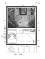
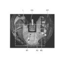
- FIG. 4 is a diagram for explaining a first example of an enlarged monitoring image displayed on the display device 50.
- FIG. 4A is a normal monitoring image displayed on the display device 50
- FIG. 4B is an enlarged monitoring image displayed on the display device 50 when a person is detected by the human detection unit 301. This is a first example.
- the peripheral image EP in the monitoring image MP (normal monitoring image) has a position closer to the shovel than the line segment L behind the shovel, that is, an area within a predetermined distance D2 from the shovel behind the shovel.
- the worker W1 is shown.
- the person detection unit 301 when detecting the worker W1, the person detection unit 301 notifies the display control unit 302 that a person has been detected. Thereby, the display control unit 302 changes the display mode of the monitoring image as described above.
- the display control unit 302 is closer to the worker W1 included in the peripheral image EP than the excavator image CG in the monitoring image MP (normal monitoring image) in FIG.
- a monitoring image MP enlarged monitoring image
- the display control unit 302 generates an enlargement monitoring image in which the excavator image CG is enlarged at the same enlargement rate in accordance with the partial area A1 of the peripheral image EP. That is, the display control unit 302 generates an enlarged monitoring image in which the partial area A1 is enlarged with the position of the worker W1 in the normal monitoring image as the center, and causes the display device 50 to display the enlarged monitoring image.
- the worker W1 is located in the approximate center of the enlarged monitoring image displayed on the display device 50 in this example. Therefore, when a person (worker W1) is detected in a predetermined area around the shovel by the human detection unit 301, the operator looks at the display content (enlarged monitoring image) on the display device 50 and detects it. It is possible to easily grasp what action a person (worker W1) is performing. Therefore, the safety at the time of operation of the shovel by the operator can be improved. In this example, since at least a part of the shovel image is included in the enlarged monitoring image, the relative positional relationship between the person (worker W1) detected by the human detection unit 301 and the shovel can be easily grasped. be able to.
- the change specification of the display mode from the normal monitoring image to the enlarged monitoring image is such that the center of the enlarged monitoring image is close to the person detected from the shovel image, and the touch panel type display unit 50A of the display device 50 or the like. It may be adjusted as appropriate by an operator's operation using the operation unit 50B by hardware. For example, the operator operates the touch panel type display unit 50A and the operation unit 50B to shift the enlargement ratio and the center of the enlargement monitoring image from the shovel image CG (shift amounts in the X axis direction and the Y axis direction on the display unit 50A). ) Etc. may be adjustable.
- the operator enlarges the normal monitoring image at a favorite center position by operating the touch panel display unit 50A or the operation unit 50B in a state where the normal monitoring image is displayed on the display unit 50A. It is possible to set the center position and the enlargement rate of the enlarged image for monitoring by performing a predetermined confirmation operation after enlarging the rate to the area where the person is detected (back, left side, or right side). For each method, a plurality of specifications may be settable.
- the operator operates the touch panel type display unit 50A and the operation unit 50B while the enlarged monitoring image is displayed on the display unit 50A, and sets the range of the peripheral image EP included in the enlarged monitoring image. The adjustment may be made as appropriate as long as the detected person is included. Thereby, the periphery monitoring system 100 can display on the display device 50 an enlarged monitoring image that suits the preference of the operator. The same applies to the cases of FIGS. 5 to 7 and FIG.
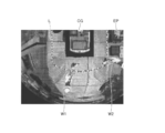
- FIG. 5 is a diagram for explaining a second example of the enlargement monitoring image displayed on the display device 50.
- FIG. 5A is a normal monitoring image displayed on the display device 50
- FIG. 5B is an enlarged monitoring image displayed on the display device 50 when a person is detected by the human detection unit 301. This is a second example.
- FIG. 5 the display unit 50A, the operation unit 50B, and the like of the display device 50 displayed in FIG. 4 are omitted, but as in the case of FIGS.
- the images (the normal monitoring image and the enlarged monitoring image) may be displayed on the display unit 50A of the display device 50 together with the driving information image IP. The same applies to the cases of FIGS.
- the peripheral image in the normal monitoring image shows the worker W1 in a position closer to the shovel than the line segment L behind the shovel, that is, in a region within a predetermined distance D2 from the shovel behind the shovel.
- the worker W2 is shown in the vicinity of the line segment L on the right rear side of the excavator, that is, in the region near the predetermined distance D2 from the shovel on the rear side of the excavator.
- the person detection unit 301 notifies the display control unit 302 that a person has been detected.
- the display control unit 302 changes the display mode of the monitoring image as described above.
- the display control unit 302 in the normal monitoring image is closer to the workers W1 and W2 included in the peripheral image EP than the excavator image CG (in this example, the worker Of the peripheral image EP including the workers W1 and W2 centered on the schematic centroid position of the figure defined by the positions of W1 and W2, that is, the substantially midpoint position of the line segment connecting the positions of the workers W1 and W2.
- An enlarged monitoring image obtained by enlarging the partial area A2 is generated and displayed on the display device 50.
- the display control unit 302 generates an enlargement monitoring image in which the excavator image CG is enlarged at the same enlargement rate in accordance with the partial area A2 of the peripheral image EP. That is, the display control unit 302 generates an enlarged monitoring image in which the partial area A2 is enlarged as it is centered on a substantially middle position of a line segment connecting the positions of the workers W1 and W2 in the normal monitoring image, It is displayed on the display device 50.
- the enlarged monitoring image displayed on the display device 50 is displayed.
- the workers W1 and W2 included are located closer to the center than the shovel image. Therefore, when two or more people (workers W1, W2) are detected by the human detection unit 301 within a predetermined area around the excavator, the operator includes the content displayed on the display device 50 (enlarged monitoring image). It is possible to easily recognize the detected person (workers W1, W2) arranged closer to the center. And an operator can grasp
- an enlarged monitoring image is generated so that all the detected two or more people (workers W1, W2) are included, all the actions of the detected two or more people are grasped. can do.
- the relative relationship between the person (workers W1, W2) detected by the human detection unit 301 and the shovel is relatively high. It is possible to easily grasp the positional relationship.
- the shovel image enlarged at the same magnification as the peripheral image is included in the enlarged monitoring image with respect to the normal monitoring image, it is detected by the human detection unit 301. The relative positional relationship between the person (workers W1, W2) and the excavator can be grasped more accurately.
- the display control unit 302 has a partial area A2 of the peripheral image EP including the workers W1 and W2 centered on the schematic centroid position of the figure defined by the positions of the workers W1 and W2 (see FIG.
- An enlarged monitoring image is generated by enlarging (see 5A), but is not limited to this mode. That is, the enlargement monitoring image (partial area A2) may be centered at a position closer to the schematic centroid position of the figure defined by the positions of the workers W1 and W2 than the excavator image CG.
- FIG. 6 is a diagram for explaining a third example of the enlarged monitoring image displayed on the display device 50.
- FIG. 6A is a normal monitoring image displayed on the display device 50
- FIG. 6B is an enlarged monitoring image displayed on the display device 50 when a person is detected by the human detection unit 301. This is a third example.
- FIG. 6A is the same as FIG. 5A except for the arrangement of the part (partial area A3) surrounded by the alternate long and short dash line, and therefore, the description will focus on the part different from FIG. 5A.
- workers W1 and W2 are shown in a predetermined area around the shovel of the normal monitoring image, as in FIG. 5A.
- the person detection unit 301 when detecting the workers W1 and W2, the person detection unit 301 notifies the display control unit 302 that a person has been detected. Thereby, the display control unit 302 changes the display mode of the monitoring image as described above.
- the display control unit 302 in the normal monitoring image is closer to the workers W1 and W2 included in the peripheral image EP than the excavator image CG (in this example, the worker A magnified monitoring image obtained by enlarging a partial area A3 (see FIG. 6A) of the peripheral image EP including the workers W1 and W2, centered on the worker W1) closest to the excavator among W1 and W2.
- the display control unit 302 generates an enlarged monitoring image in which the excavator image CG is enlarged at the same enlargement rate in accordance with the partial area A3 of the peripheral image EP. That is, the display control unit 302 generates an enlarged monitoring image in which the partial area A3 is enlarged as it is centered on the position of the worker W1 in the normal monitoring image, and causes the display device 50 to display the enlarged monitoring image.
- the worker W1 closest to the shovel among the two or more people (workers W1, W2) detected by the human detection unit 301 is displayed.
- the operator confirms the display content (enlarged monitoring image) on the display device 50 when two or more people (workers W1, W2) are detected within a predetermined area around the shovel by the human detection unit 301.
- the enlarged monitoring image is generated so that all of the detected two or more people are included, so that all the behaviors of the detected two or more people are grasped. be able to.
- at least a part of the shovel image is included in the enlarged monitoring image, so the person (workers W1, W2) detected by the human detection unit 301 and the shovel are relative to each other. It is possible to easily grasp the positional relationship.
- the shovel image enlarged at the same enlargement rate as the peripheral image is included in the enlarged monitoring image with respect to the normal monitoring image, it is detected by the human detection unit 301. The relative positional relationship between the person (workers W1, W2) and the excavator can be grasped more accurately.
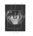
- FIG. 7 is a diagram for explaining a fourth example of the enlarged monitoring image displayed on the display device 50.
- FIG. 7A is a normal monitoring image displayed on the display device 50
- FIG. 7B is an enlarged monitoring image displayed on the display device 50 when a person is detected by the human detection unit 301. This is a fourth example.
- the display device 50 has a vertically long rectangular screen (for example, a screen with an aspect ratio of 9:16).
- 7A is the same as FIG. 4A except that the display device 50 is a vertically long rectangular screen and the arrangement of a portion (partial region A4) surrounded by a one-dot chain line is different from FIG. 4A.
- the explanation will focus on the part.
- the peripheral image in the normal monitoring image shows the worker W1 in the predetermined area around the excavator (backward) as in FIG. 4A.
- the person detection unit 301 when detecting the worker W1, the person detection unit 301 notifies the display control unit 302 that a person has been detected. Thereby, the display control unit 302 changes the display mode of the monitoring image as described above.
- the display control unit 302 in the normal monitoring image is closer to the worker W1 included in the peripheral image EP than the excavator image CG (in this example, the worker W1's
- An enlarged monitoring image is generated by enlarging a partial area A4 of the peripheral image EP including the worker W1 centering on the position) and displayed on the display device 50.
- the display control unit 302 includes a partial area A4 of the peripheral image EP that includes all the neighboring areas closer to the excavator (excavator image) than the line segment L, that is, all neighboring areas within the predetermined distance D2 from the shovel.
- An enlarged monitoring image is generated by enlarging (see FIG. 7A).
- the display control unit 302 generates an enlargement monitoring image in which the excavator image CG is enlarged at the same enlargement rate in accordance with the partial area A4 of the peripheral image EP. That is, the display control unit 302 enlarges the partial area A4 as it is, including the entire vicinity area within the predetermined distance D2 from the excavator in the peripheral image EP with the position of the worker W1 in the normal monitoring image as the center.
- a monitoring image is generated and displayed on the display device 50.
- the worker W1 is located in the approximate center of the enlarged monitoring image displayed on the display device 50 in this example, as in the first example. Therefore, when a person (worker W1) is detected in a predetermined area around the shovel by the human detection unit 301, the operator looks at the display content (enlarged monitoring image) on the display device 50 and detects it. It is possible to easily grasp what action a person (worker W1) is performing. Further, in this example, as in the first example and the like, since at least a part of the shovel image is included in the enlarged monitoring image, the person (worker W1) detected by the human detection unit 301 and the shovel are relatively relative. The positional relationship can be easily grasped.
- the shovel image enlarged at the same enlargement rate as the peripheral image is included in the enlarged monitoring image with respect to the normal monitoring image, it is detected by the human detection unit 301.
- the relative positional relationship between the person (worker W1) and the excavator can be grasped more accurately.
- the operator since all of the neighboring areas within the predetermined distance D2 from the shovel are included in the enlarged monitoring image, the operator can detect the behavior of the detected person while checking the situation of the neighboring area near the shovel. Can be grasped. Therefore, the safety at the time of operation of the shovel by the operator can be further enhanced.
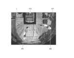
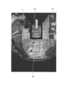
- FIG. 8 is a diagram illustrating an example of another viewpoint monitoring image displayed on the display device 50.
- description will be given on the assumption that FIG. 8 is a different viewpoint monitoring image switched from the normal monitoring image of FIG. 4A.
- the person detection unit 301 detects the worker W1.
- the display control unit 302 is notified that a person has been detected. Thereby, the display control unit 302 changes the display mode of the monitoring image as described above.
- the display control unit 302 is based on the captured image of the imaging device 40 and is obliquely above the rear of the shovel (in this example, an angular direction 45 degrees above the horizontal plane behind the shovel.
- the peripheral image EP is generated as a viewpoint conversion image viewed from the virtual viewpoint (the same applies to FIG. 9).
- the display control unit 302 displays the shovel image CG together with the excavator image CG viewed from a virtual viewpoint obliquely above and behind the shovel similar to the surrounding image, and the relative positional relationship between the shovel and the imaging range of the imaging device 40.
- Another viewpoint monitoring image including the peripheral image EP arranged around is displayed on the display device 50.
- the operator can virtually realize the state in which the operator and the excavator are viewed obliquely from above the excavator, the operator can determine the positional relationship between the person (worker W1) detected behind the excavator and the excavator. It becomes easy to grasp (feeling of distance).
- the display control unit 302 may generate another viewpoint monitoring image including a peripheral image as a viewpoint conversion image viewed from a virtual viewpoint diagonally forward of the excavator and display the generated image on the display device 50.
- a viewpoint monitoring image including a peripheral image as a viewpoint conversion image viewed from a virtual viewpoint diagonally forward of the excavator and display the generated image on the display device 50.
- the display control unit 302 when the person detection unit 301 detects a person relatively behind the shovel, detects an obliquely upward direction in which the angle direction of the virtual viewpoint with respect to the horizontal plane is shifted from directly above to the front or back.
- Another viewpoint monitoring image including a peripheral image as a viewpoint conversion image viewed from the above may be generated and displayed on the display device 50.
- the periphery monitoring system 100 can prompt the operator to grasp the person (worker W1) detected in the monitoring image.
- the periphery monitoring system 100 shifts the angle direction of the virtual viewpoint with respect to the horizontal plane relative to the side where the person is present as viewed from the shovel (in the case of this example), as described above.
- the periphery monitoring system 100 shifts the angle direction of the virtual viewpoint with respect to the horizontal plane to the side where the person is present relative to the shovel (in the case of this example, the rear), so that the area behind the shovel including the worker And the operator's situation is easily grasped by the operator.
- the display control unit 302 changes the angular direction of the virtual viewpoint with respect to the horizontal plane from right above to right.
- another viewpoint monitoring image including a peripheral image as a viewpoint conversion image viewed from an obliquely upward direction shifted to the left may be generated and displayed on the display device 50.
- the periphery monitoring system 100 prompts the operator to grasp the detected person (worker W1) in the monitoring image, as in the case where a person who is relatively behind when detected from the shovel is detected. be able to.
- the imaging device 40 may include a camera (front camera) that images the front of the excavator (upper revolving unit 3), and the human detection unit 301 also detects a person in a predetermined area including the front of the shovel. May be detected.
- the display control unit 302 may generate a normal monitoring image including a peripheral image obtained by combining a bird's-eye image obtained by viewing a horizontal 360 ° range around the shovel from directly above and a horizontal image. Then, the display control unit 302 determines the angle direction of the virtual viewpoint with respect to the horizontal plane when the person detection unit 301 detects a person who is relatively forward when viewed from the shovel, as in the case where the person behind is detected.
- Another viewpoint monitoring image including a peripheral image as a viewpoint conversion image viewed from an obliquely upward direction shifted from directly above to the front or rear may be generated and displayed on the display device 50.
- the periphery monitoring system 100 prompts the operator to grasp the detected person (worker W1) in the monitoring image, as in the case where a person who is relatively behind when detected from the shovel is detected. be able to. The same applies to the case of partial viewpoint monitoring images.
- FIG. 9 is a diagram illustrating an example of the partial viewpoint monitoring image displayed on the display device 50.
- description will be given on the assumption that FIG. 8 is a different viewpoint monitoring image switched from the normal monitoring image of FIG. 4A.
- the person detection unit 301 detects the worker W1.
- the display control unit 302 is notified that a person has been detected. Thereby, the display control unit 302 changes the display mode of the monitoring image as described above.
- the display control unit 302 detects a normal monitoring image, which is a viewpoint conversion image from a virtual viewpoint obliquely rearward of the excavator, based on a captured image of the imaging device 40.
- a peripheral image is generated as a viewpoint conversion image corresponding to a partial region including a portion where a person is present. Then, the display control unit 302 matches the relative position relationship between the part of the shovel image CG viewed from a virtual viewpoint obliquely above the shovel rearward and the image pickup range of the image pickup device 40 as with the surrounding image.
- a partial viewpoint monitoring image including a peripheral image EP arranged around (a part of) CG is displayed on the display device 50.
- the operator can virtually realize the state where the operator and the excavator are seen from diagonally above the excavator, so that the operator can detect the person ( It becomes easy to grasp the positional relationship (sense of distance) between the worker W1) and the excavator. Further, in this example, since only a partial area including the detected person in the normal monitoring image is displayed on the display device 50 as the partial viewpoint monitoring image, the operator can display the status of the detected person. It becomes easier to grasp.
- the display control unit 302 displays a partial viewpoint monitoring image including a peripheral image as a viewpoint conversion image obtained by viewing a partial region including a person from which a normal monitoring image is detected from a virtual viewpoint diagonally forward of the shovel. It may be generated and displayed on the display device 50.
- a partial viewpoint monitoring image including a peripheral image as a viewpoint conversion image obtained by viewing a partial region including a person from which a normal monitoring image is detected from a virtual viewpoint diagonally forward of the shovel. It may be generated and displayed on the display device 50.
- the display control unit 302 when the person detection unit 301 detects a person relatively behind the shovel, detects an obliquely upward direction in which the angle direction of the virtual viewpoint with respect to the horizontal plane is shifted from directly above to the front or back. Generating and displaying a partial viewpoint monitoring image including a peripheral image as a viewpoint conversion image corresponding to a partial area including a portion where the detected person of the normal monitoring image is present. You may display on the apparatus 50. FIG. Thereby, the periphery monitoring system 100 can further prompt the operator to grasp the person (worker W1) detected in the monitoring image.
- the display control unit 302 changes the angular direction of the virtual viewpoint with respect to the horizontal plane from right above to right.
- it is a viewpoint conversion image viewed from an obliquely upward direction shifted to the left, and includes a peripheral image as a viewpoint conversion image corresponding to a partial area including a portion where a person is detected in the normal monitoring image
- a viewpoint monitoring image may be generated and displayed on the display device 50.
- the periphery monitoring system 100 further grasps the detected person (worker W1) in the monitoring image with respect to the operator, as in the case where a person who is relatively behind when detected from the shovel is detected. Can be urged.
- the partial viewpoint monitoring image shown in FIG. 9 corresponds to a partial area A2 of the different viewpoint monitoring image of FIG. Therefore, the display control unit 302 generates a different viewpoint monitoring image based on the captured image of the imaging device 40, and then cuts out and enlarges a partial area A2 of the generated different viewpoint conversion image for partial viewpoint monitoring. An image may be generated.
- FIG. 10 is a flowchart schematically showing an example of display processing by the periphery monitoring system 100 (display control unit 302) according to the present embodiment.
- the processing according to this flowchart is performed when, for example, the display of the normal monitoring image or the human detection monitoring image on the display device 50 is started in accordance with a predetermined start operation or a predetermined start condition by the operator. And is repeatedly executed at predetermined time intervals. Further, the processing according to this flowchart is, for example, the display of the monitoring image (the normal monitoring image or the human detection monitoring image) on the display device 50 is terminated in accordance with a predetermined end operation or a predetermined end condition by the operator. When it is done, the process is terminated.
- step S101 the display control unit 302 determines whether or not the function for changing the display mode of the monitoring image at the time of human detection is turned on. If the function is turned on, the display control unit 302 proceeds to step S102, and otherwise, ends the current process.
- step S102 the display control unit 302 determines whether the human detection unit 301 has detected a person within a predetermined area around the shovel. If the human detection unit 301 has not detected a person, the display control unit 302 proceeds to step S104. If the human detection unit 301 has detected a person, the display control unit 302 proceeds to step S106.
- step S104 the display control unit 302 causes the display device 50 to display a normal monitoring image.
- step S106 the display control unit 302 causes the display device 50 to display a monitoring image for human detection.
- the display control unit 302 uses an operator or the like in advance from two or more human detection monitoring images among the enlargement monitoring image, the different viewpoint monitoring image, and the partial viewpoint monitoring image by the processing in this step.
- One person detection monitoring image selected in accordance with the selection operation may be displayed.
- the display control unit 302 displays only one of the monitoring images for human detection among the enlargement monitoring image, the different viewpoint monitoring image, and the partial viewpoint monitoring image by the processing of this step. 50 may be displayed.
- step S108 the display control unit 302 switches the previous image on the display device 50 (image switching from the normal monitoring image to the human detection monitoring image, or from the human detection monitoring image to the normal monitoring image). It is determined whether or not a predetermined time has elapsed since the image switching.
- the display control unit 302 repeats the process of this step when the predetermined time or more has not elapsed since the previous image switching in the display device 50, and when the predetermined time or more has elapsed since the previous screen switching (or according to this flowchart). When the screen is not switched after the start of the process), the process returns to step S102 to repeat the process according to this flowchart.
- the display control unit 302 is a partial region of the peripheral image in the normal monitoring image when the human detection unit 301 detects a person within a predetermined region, and is more than the shovel image.
- the display device 50 is caused to display an enlarged monitoring image in which a partial region including a person is enlarged with a position near the person included in the peripheral image as a center. Accordingly, when a person is detected around the shovel by the person detection unit 301, an enlarged monitoring image in which a portion including the detected person is arranged closer to the center is displayed on the display device 50.
- the operator can easily confirm the detected person displayed near the center of the screen of the display device 50 and can easily grasp the state of the detected person's action content and the like. Therefore, the periphery monitoring system 100 can further enhance the safety when the shovel is operated by the operator.
- the display control unit 302 approaches the person who has detected the angle direction with respect to the horizontal plane of the virtual viewpoint from the top with respect to the shovel.
- Another viewpoint monitoring image including a peripheral image as a viewpoint conversion image viewed from an obliquely upward direction shifted in the direction or away from the camera is generated and displayed on the display device 50.
- the periphery monitoring system 100 can prompt the operator to grasp the person detected by the monitoring image as described above. Therefore, the periphery monitoring system 100 can further enhance the safety when the shovel is operated by the operator.
- the display control unit 302 approaches the person who has detected the angle direction with respect to the horizontal plane of the virtual viewpoint from the top with respect to the shovel.
- a viewpoint conversion image viewed from an obliquely upward direction shifted in a direction or away from the image, and includes a peripheral image as a viewpoint conversion image corresponding to a partial region including a detected person portion in the normal monitoring image
- a partial viewpoint monitoring image is generated and displayed on the display device 50.
- the display control unit 302 displays the enlarged image as the enlarged monitoring image.
- the center of the partial area including the person in the normal monitoring image may be changed.
- the display control unit 302 is a partial region of the peripheral image in the normal monitoring image, and the shovel
- the display device 50 displays an enlargement monitoring image in which a partial region including a person is enlarged, centering on a position closer to the person included in the peripheral image than the image.
- the display control unit 302 includes a person who is centered on the shovel image in the normal monitoring image. An enlargement monitoring image in which the partial area is enlarged is displayed on the display device 50.
- the operator can more easily understand the state of the detected person, and the safety of the detected person can be reliably ensured.
- the operator can grasp the state of the detected person while grasping the entire state of the excavator, and can easily take future safety actions. Become.
- an enlargement monitoring image is generated in which the excavator image is also enlarged in accordance with a partial region of the peripheral image.
- the excavator image is also enlarged in accordance with a partial region of the peripheral image.
- An image may be generated.
- an enlarged monitoring image including at least a part of the shovel image is generated.
- an enlarged monitoring image not including the shovel image may be generated.
- the display control unit 302 includes the rear camera 40B on the left side in an area that does not include the detected person in the normal monitoring image.
- a monitoring image in which a captured image (through image) showing a detected person in the captured images of the camera 40L and the right-side camera 40R is superimposed and generated as it is is generated and displayed on the display device 50. You may let them.
- the operator can easily grasp the situation of the detected person and can also visually recognize the through image in which the detected person is reflected. This makes it easier for the operator to grasp the detected person's situation.
- the controller 30 (periphery monitoring system 100) detects a person as a monitoring target, but includes a person or an object other than a person (for example, another work machine or vehicle around a shovel) , Temporarily placed construction materials, etc.) may be detected.
- the controller 30 (display control unit 302) changes the display mode of the monitoring image in the same manner as described above depending on whether or not the object to be monitored is detected.
Abstract
Description
作業機械のキャビン内に設けられる表示装置と、
前記作業機械の周辺を撮像する撮像装置と、
前記撮像装置の撮像画像に基づき前記作業機械の周辺画像を生成する画像生成部と、
前記作業機械を模式的に表す作業機械画像と、前記作業機械と前記撮像装置の撮像範囲との相対位置関係に合わせて、前記作業機械画像の周囲に配置される前記周囲画像とを含む監視用画像を前記表示装置に表示させる表示制御部と、
前記作業機械の周辺の所定領域内で人を検知する人検知部と、を備え、
前記表示制御部は、前記人検知部により前記所定領域内で人が検知された場合、前記監視用画像における前記周辺画像の一部領域であって、前記作業機械画像よりも前記周辺画像に含まれる前記人に近い位置を中心とし、前記人が含まれる一部領域を拡大した拡大監視用画像を前記表示装置に表示させる、
作業機械用周辺監視システムが提供される。
まず、図1を参照して、本実施形態に係る周辺監視システム100(図2参照)が搭載される作業機械について説明をする。
次に、図2A,図2Bを参照して、周辺監視システム100の構成について説明する。
次に、表示制御部302の特徴的な機能について説明をする。
以下、図4~図9を参照して、表示装置50に表示される監視用画像の表示態様の変更の詳細について説明をする。
次に、図10を参照して、本実施形態に係る周辺監視システム100(表示制御部302)による監視用画像を表示装置50に表示させる処理(表示処理)の処理フローについて説明をする。以下、拡大監視用画像、別視点監視用画像、及び、部分別視点監視用画像を総括的に「人検知時監視用画像」と称する場合がある。
このように、本実施形態では、表示制御部302は、人検知部301により所定領域内で人が検知された場合、通常監視用画像における周辺画像の一部領域であって、ショベル画像よりも周辺画像に含まれる人に近い位置を中心とする、人が含まれる一部領域を拡大した拡大監視用画像を表示装置50に表示させる。これにより、人検知部301によりショベルの周辺に人が検知された場合に、検知された人が含まれる部分が中央寄りに配置された拡大監視用画像が表示装置50に表示される。そのため、オペレータは、表示装置50の画面の中央寄りに表示される検知された人を容易に確認できると共に、検知された人の行動内容等の状態を容易に把握することができる。よって、周辺監視システム100は、オペレータによるショベルの操作時における安全性を更に高めることができる。
301 人検知部
302 表示制御部
40 撮像装置
40B 後方カメラ
40L 左側方カメラ
40R 右側方カメラ
50 表示装置
100 周辺監視システム(作業機械用周辺監視システム)
Claims (8)
- 作業機械のキャビン内に設けられる表示装置と、
前記作業機械の周辺を撮像する撮像装置と、
前記撮像装置の撮像画像に基づき前記作業機械の周辺画像を生成すると共に、前記作業機械を模式的に表す作業機械画像と、前記作業機械と前記撮像装置の撮像範囲との相対位置関係に合わせて、前記作業機械画像の周囲に配置される前記周辺画像とを含む監視用画像を前記表示装置に表示させる表示制御部と、
前記作業機械の周辺の所定領域内で人を検知する人検知部と、を備え、
前記表示制御部は、前記人検知部により前記所定領域内で人が検知された場合、前記監視用画像における前記周辺画像の一部領域であって、前記作業機械画像よりも前記周辺画像に含まれる前記人に近い位置を中心とする、前記人が含まれる一部領域を拡大した拡大監視用画像を前記表示装置に表示させる、
作業機械用周辺監視システム。 - 前記表示制御部は、前記人検知部により前記所定領域内で人が検知された場合、前記作業機械画像の少なくとも一部を含む前記拡大監視用画像を前記表示装置に表示させる、
請求項1に記載の作業機械用周辺監視システム。 - 前記表示制御部は、前記人検知部により前記所定領域内で人が検知された場合、前記周辺画像に含まれる前記人の位置を中心とする前記一部領域を拡大した前記拡大監視用画像を前記表示装置に表示させる、
請求項1又は2に記載の作業機械用周辺監視システム。 - 前記表示制御部は、前記人検知部により前記所定領域内で2以上の人が検知された場合、前記作業機械画像よりも、前記周辺画像に含まれる前記2以上の人の位置で規定される図形の略図心位置に近い位置を中心とする、前記2以上の人が含まれる前記一部領域を拡大した前記拡大監視用画像を前記表示装置に表示させる、
請求項1又は2に記載の作業機械用周辺監視システム。 - 前記表示制御部は、前記人検知部により前記所定領域内で2以上の人が検知された場合、前記図形の略図心位置を中心とする、前記2以上の人が含まれる前記一部領域を拡大した前記拡大監視用画像を前記表示装置に表示させる、
請求項4に記載の作業機械用周辺監視システム。 - 前記表示制御部は、前記人検知部により前記所定領域内で2以上の人が検知された場合、前記周辺画像に含まれる前記2以上の人のうちの前記作業機械に最も近い人の位置を中心とする前記一部領域を拡大した前記拡大監視用画像を前記表示装置に表示させる、
請求項1又は2に記載の作業機械用周辺監視システム。 - 前記表示制御部は、前記人検知部により前記所定領域内で人が検知された場合、前記一部領域に合わせて前記作業機械画像も拡大した前記拡大監視用画像を前記表示装置に表示させる、
請求項2に記載の作業機械用周辺監視システム。 - 前記表示制御部は、前記人検知部により前記所定領域内で人が検知された場合、前記周辺画像における前記作業機械から所定距離内の近傍領域の全てが含まれる前記一部領域を拡大した前記拡大監視用画像を前記表示装置に表示させる、
請求項1乃至7の何れか一項に記載の作業機械用周辺監視システム。
Priority Applications (5)
| Application Number | Priority Date | Filing Date | Title |
|---|---|---|---|
| JP2018549017A JP7171436B2 (ja) | 2016-11-01 | 2017-10-31 | 作業機械用周辺監視システム、表示装置 |
| KR1020187035110A KR102256384B1 (ko) | 2016-11-01 | 2017-10-31 | 작업기계용 주변감시시스템 |
| CN201780036721.XA CN109314769B (zh) | 2016-11-01 | 2017-10-31 | 施工机械用周边监视系统 |
| EP17866645.9A EP3537713B1 (en) | 2016-11-01 | 2017-10-31 | Surroundings monitoring system for a work machine |
| US16/363,194 US11047113B2 (en) | 2016-11-01 | 2019-03-25 | Surroundings monitoring system for work machine |
Applications Claiming Priority (2)
| Application Number | Priority Date | Filing Date | Title |
|---|---|---|---|
| JP2016-214714 | 2016-11-01 | ||
| JP2016214714 | 2016-11-01 |
Related Child Applications (1)
| Application Number | Title | Priority Date | Filing Date |
|---|---|---|---|
| US16/363,194 Continuation US11047113B2 (en) | 2016-11-01 | 2019-03-25 | Surroundings monitoring system for work machine |
Publications (1)
| Publication Number | Publication Date |
|---|---|
| WO2018084146A1 true WO2018084146A1 (ja) | 2018-05-11 |
Family
ID=62076199
Family Applications (1)
| Application Number | Title | Priority Date | Filing Date |
|---|---|---|---|
| PCT/JP2017/039339 WO2018084146A1 (ja) | 2016-11-01 | 2017-10-31 | 作業機械用周辺監視システム |
Country Status (6)
| Country | Link |
|---|---|
| US (1) | US11047113B2 (ja) |
| EP (1) | EP3537713B1 (ja) |
| JP (1) | JP7171436B2 (ja) |
| KR (1) | KR102256384B1 (ja) |
| CN (1) | CN109314769B (ja) |
| WO (1) | WO2018084146A1 (ja) |
Cited By (8)
| Publication number | Priority date | Publication date | Assignee | Title |
|---|---|---|---|---|
| JP2020183623A (ja) * | 2019-04-26 | 2020-11-12 | 住友建機株式会社 | ショベル |
| WO2020235176A1 (ja) * | 2019-05-21 | 2020-11-26 | コベルコ建機株式会社 | 作業機械 |
| JP2021030804A (ja) * | 2019-08-21 | 2021-03-01 | 株式会社竹内製作所 | 作業用車両 |
| US20210395980A1 (en) * | 2019-01-23 | 2021-12-23 | Komatsu Ltd. | System and method for work machine |
| WO2022054345A1 (ja) | 2020-09-14 | 2022-03-17 | コニカミノルタ株式会社 | 安全監視装置、安全監視方法、及び、プログラム |
| WO2022080027A1 (ja) * | 2020-10-12 | 2022-04-21 | ヤンマーホールディングス株式会社 | 作業車両 |
| EP3940148A4 (en) * | 2019-03-15 | 2022-12-21 | Yanmar Power Technology Co., Ltd. | CONTACT PROTECTION DEVICE FOR A WORKING MACHINE |
| WO2024057894A1 (ja) * | 2022-09-15 | 2024-03-21 | 株式会社小松製作所 | 作業機械の表示システム、作業機械、及び作業機械の表示方法 |
Families Citing this family (5)
| Publication number | Priority date | Publication date | Assignee | Title |
|---|---|---|---|---|
| JP7155516B2 (ja) * | 2017-12-20 | 2022-10-19 | コベルコ建機株式会社 | 建設機械 |
| KR20220002343A (ko) * | 2019-04-26 | 2022-01-06 | 스미토모 겐키 가부시키가이샤 | 표시장치, 쇼벨, 정보처리장치 |
| WO2020218452A1 (ja) * | 2019-04-26 | 2020-10-29 | 住友建機株式会社 | ショベル、作業現場の安全装備確認システム |
| JP2021042638A (ja) * | 2019-09-13 | 2021-03-18 | 株式会社小松製作所 | 作業機械の表示システムおよび作業機械の表示方法 |
| CN113128742B (zh) * | 2020-01-14 | 2024-03-22 | 中联重科股份有限公司 | 工程机械的施工方法、装置、可读存储介质和处理器 |
Citations (5)
| Publication number | Priority date | Publication date | Assignee | Title |
|---|---|---|---|---|
| JP2011162993A (ja) * | 2010-02-09 | 2011-08-25 | Sumitomo (Shi) Construction Machinery Co Ltd | 作業機械のモニタ装置 |
| JP2012082608A (ja) * | 2010-10-08 | 2012-04-26 | Sumitomo (Shi) Construction Machinery Co Ltd | 作業機械のモニタ装置 |
| JP2014183497A (ja) * | 2013-03-19 | 2014-09-29 | Sumitomo Heavy Ind Ltd | 作業機械用周辺監視装置 |
| JP2014183500A (ja) * | 2013-03-19 | 2014-09-29 | Sumitomo Heavy Ind Ltd | 作業機械用周辺監視装置 |
| JP2015184839A (ja) * | 2014-03-21 | 2015-10-22 | 富士通テン株式会社 | 画像生成装置、画像表示システム及び画像生成方法 |
Family Cites Families (30)
| Publication number | Priority date | Publication date | Assignee | Title |
|---|---|---|---|---|
| EP1083076A3 (en) * | 1999-09-07 | 2005-01-12 | Mazda Motor Corporation | Display apparatus for vehicle |
| JP4010444B2 (ja) | 2002-02-28 | 2007-11-21 | シャープ株式会社 | 全方位監視制御システム、全方位監視制御方法および全方位監視制御プログラム |
| US20030193562A1 (en) * | 2002-04-15 | 2003-10-16 | Corzillus Brian S. | Natural vision-based video surveillance system |
| JP3982504B2 (ja) * | 2004-01-23 | 2007-09-26 | 日産自動車株式会社 | 車両用暗視カメラ装置および表示装置 |
| EP2390154A1 (en) * | 2005-10-31 | 2011-11-30 | Toyota Jidosha Kabushiki Kaisha | Parking support device |
| JP4707109B2 (ja) | 2006-03-02 | 2011-06-22 | アルパイン株式会社 | 複数カメラ撮影画像処理方法及び装置 |
| TW200739125A (en) * | 2006-04-14 | 2007-10-16 | Quarton Inc | Target searching device and image displaying method thereof |
| US8170787B2 (en) * | 2008-04-15 | 2012-05-01 | Caterpillar Inc. | Vehicle collision avoidance system |
| JP5182042B2 (ja) * | 2008-11-28 | 2013-04-10 | 富士通株式会社 | 画像処理装置、画像処理方法及びコンピュータプログラム |
| TW201103787A (en) * | 2009-07-31 | 2011-02-01 | Automotive Res & Testing Ct | Obstacle determination system and method utilizing bird's-eye images |
| JP5604146B2 (ja) | 2010-03-25 | 2014-10-08 | 富士通テン株式会社 | 車載照明装置、画像処理装置、画像表示システム及び照明方法 |
| CN102947515B (zh) | 2010-06-18 | 2015-07-29 | 日立建机株式会社 | 作业机械的周围监视装置 |
| US9019347B2 (en) * | 2011-10-13 | 2015-04-28 | Aisin Seiki Kabushiki Kaisha | Image generator |
| JP5888956B2 (ja) * | 2011-12-13 | 2016-03-22 | 住友建機株式会社 | ショベル及び該ショベルの周囲画像表示方法 |
| JP6167042B2 (ja) * | 2012-01-12 | 2017-07-19 | 日立建機株式会社 | 自走式産業機械の周囲監視装置 |
| KR20130097913A (ko) * | 2012-02-27 | 2013-09-04 | 주식회사 경우시스테크 | 파노라마 영상이 제공되는 안전 시스템을 구비한 굴삭기 |
| JP6029306B2 (ja) * | 2012-03-29 | 2016-11-24 | 住友建機株式会社 | 作業機械用周辺監視装置 |
| JP5988683B2 (ja) * | 2012-05-15 | 2016-09-07 | 日立建機株式会社 | 自走式産業機械の表示装置 |
| JP5814187B2 (ja) * | 2012-06-07 | 2015-11-17 | 日立建機株式会社 | 自走式産業機械の表示装置 |
| JP5938292B2 (ja) * | 2012-08-03 | 2016-06-22 | 日立建機株式会社 | 運搬車両の監視装置 |
| JP6029941B2 (ja) * | 2012-11-08 | 2016-11-24 | 住友重機械工業株式会社 | 舗装機械用画像生成装置 |
| CN102938827B (zh) * | 2012-11-29 | 2016-05-11 | 深圳英飞拓科技股份有限公司 | 一种分层监控指挥系统及跨摄像头虚拟跟踪方法 |
| JP2014110604A (ja) * | 2012-12-04 | 2014-06-12 | Denso Corp | 車両周辺監視装置 |
| WO2014123228A1 (ja) * | 2013-02-08 | 2014-08-14 | 日立建機株式会社 | 旋回式作業機械の周囲監視装置 |
| JP6456584B2 (ja) * | 2013-03-19 | 2019-01-23 | 住友重機械工業株式会社 | 作業機械用周辺監視装置 |
| EP3023125B1 (en) * | 2013-07-16 | 2021-01-27 | Beijing Mechanical Equipment Institute | Control method of a fire truck for high-rise and super high-rise building firefighting |
| JP6165085B2 (ja) * | 2014-03-07 | 2017-07-19 | 日立建機株式会社 | 作業機械の周辺監視装置 |
| JP6204884B2 (ja) * | 2014-07-25 | 2017-09-27 | 日立建機株式会社 | 旋回式作業機の周囲表示装置 |
| JPWO2016157463A1 (ja) * | 2015-03-31 | 2018-01-18 | 株式会社小松製作所 | 作業機械の周辺監視装置 |
| US20160301863A1 (en) * | 2015-04-10 | 2016-10-13 | Caterpillar Inc. | Image processing system for generating a surround-view image |
-
2017
- 2017-10-31 WO PCT/JP2017/039339 patent/WO2018084146A1/ja unknown
- 2017-10-31 CN CN201780036721.XA patent/CN109314769B/zh active Active
- 2017-10-31 JP JP2018549017A patent/JP7171436B2/ja active Active
- 2017-10-31 EP EP17866645.9A patent/EP3537713B1/en active Active
- 2017-10-31 KR KR1020187035110A patent/KR102256384B1/ko active IP Right Grant
-
2019
- 2019-03-25 US US16/363,194 patent/US11047113B2/en active Active
Patent Citations (5)
| Publication number | Priority date | Publication date | Assignee | Title |
|---|---|---|---|---|
| JP2011162993A (ja) * | 2010-02-09 | 2011-08-25 | Sumitomo (Shi) Construction Machinery Co Ltd | 作業機械のモニタ装置 |
| JP2012082608A (ja) * | 2010-10-08 | 2012-04-26 | Sumitomo (Shi) Construction Machinery Co Ltd | 作業機械のモニタ装置 |
| JP2014183497A (ja) * | 2013-03-19 | 2014-09-29 | Sumitomo Heavy Ind Ltd | 作業機械用周辺監視装置 |
| JP2014183500A (ja) * | 2013-03-19 | 2014-09-29 | Sumitomo Heavy Ind Ltd | 作業機械用周辺監視装置 |
| JP2015184839A (ja) * | 2014-03-21 | 2015-10-22 | 富士通テン株式会社 | 画像生成装置、画像表示システム及び画像生成方法 |
Non-Patent Citations (1)
| Title |
|---|
| See also references of EP3537713A4 * |
Cited By (11)
| Publication number | Priority date | Publication date | Assignee | Title |
|---|---|---|---|---|
| US20210395980A1 (en) * | 2019-01-23 | 2021-12-23 | Komatsu Ltd. | System and method for work machine |
| EP3940148A4 (en) * | 2019-03-15 | 2022-12-21 | Yanmar Power Technology Co., Ltd. | CONTACT PROTECTION DEVICE FOR A WORKING MACHINE |
| JP2020183623A (ja) * | 2019-04-26 | 2020-11-12 | 住友建機株式会社 | ショベル |
| WO2020235176A1 (ja) * | 2019-05-21 | 2020-11-26 | コベルコ建機株式会社 | 作業機械 |
| JP2020189722A (ja) * | 2019-05-21 | 2020-11-26 | コベルコ建機株式会社 | 作業機械 |
| JP7379866B2 (ja) | 2019-05-21 | 2023-11-15 | コベルコ建機株式会社 | 作業機械 |
| JP2021030804A (ja) * | 2019-08-21 | 2021-03-01 | 株式会社竹内製作所 | 作業用車両 |
| JP7096216B2 (ja) | 2019-08-21 | 2022-07-05 | 株式会社竹内製作所 | 作業用車両 |
| WO2022054345A1 (ja) | 2020-09-14 | 2022-03-17 | コニカミノルタ株式会社 | 安全監視装置、安全監視方法、及び、プログラム |
| WO2022080027A1 (ja) * | 2020-10-12 | 2022-04-21 | ヤンマーホールディングス株式会社 | 作業車両 |
| WO2024057894A1 (ja) * | 2022-09-15 | 2024-03-21 | 株式会社小松製作所 | 作業機械の表示システム、作業機械、及び作業機械の表示方法 |
Also Published As
| Publication number | Publication date |
|---|---|
| EP3537713A1 (en) | 2019-09-11 |
| US20190218754A1 (en) | 2019-07-18 |
| KR102256384B1 (ko) | 2021-05-25 |
| EP3537713A4 (en) | 2019-10-16 |
| JPWO2018084146A1 (ja) | 2019-09-19 |
| CN109314769A (zh) | 2019-02-05 |
| KR20190077246A (ko) | 2019-07-03 |
| US11047113B2 (en) | 2021-06-29 |
| EP3537713B1 (en) | 2021-09-01 |
| JP7171436B2 (ja) | 2022-11-15 |
| CN109314769B (zh) | 2022-06-07 |
Similar Documents
| Publication | Publication Date | Title |
|---|---|---|
| WO2018084146A1 (ja) | 作業機械用周辺監視システム | |
| JP6427597B2 (ja) | 作業機械の周辺監視装置及び作業機械の周辺監視方法 | |
| JP6216097B2 (ja) | 作業機械の周辺監視装置 | |
| KR101843382B1 (ko) | 크롤러식 작업 기계의 주변 감시 장치 | |
| JP6200121B2 (ja) | 作業機械の周辺監視装置 | |
| JP5750344B2 (ja) | 作業機の周囲監視装置 | |
| WO2019244574A1 (ja) | 掘削機、情報処理装置 | |
| JP7407178B2 (ja) | ショベル | |
| JP2008163719A (ja) | 作業機械の周囲監視装置 | |
| JP7358070B2 (ja) | ショベル | |
| JP7463354B2 (ja) | ショベル | |
| WO2019189399A1 (ja) | ショベル | |
| JP2016194237A (ja) | 作業機械 | |
| JP2020183623A (ja) | ショベル | |
| JP6980391B2 (ja) | 作業機械用周辺監視システム | |
| EP3733982B1 (en) | Shovel and output device of shovel | |
| JP2020159045A (ja) | 建設機械 | |
| WO2021187082A1 (ja) | 作業機械および作業機械の制御方法 | |
| JP7396987B2 (ja) | ショベル | |
| JP2020183622A (ja) | ショベル、ショベルのシリーズ | |
| JP7399836B2 (ja) | 作業車両 | |
| JP2023176830A (ja) | 作業機械の制御方法、作業機械用制御プログラム、作業機械用制御システム及び作業機械 | |
| JP2023129871A (ja) | 作業機械用制御システム、作業機械、作業機械の制御方法及び作業機械用制御プログラム | |
| JP2023129872A (ja) | 作業機械用制御システム、作業機械、作業機械の制御方法及び作業機械用制御プログラム | |
| JP2022157923A (ja) | ショベル |
Legal Events
| Date | Code | Title | Description |
|---|---|---|---|
| ENP | Entry into the national phase |
Ref document number: 20187035110 Country of ref document: KR Kind code of ref document: A |
|
| 121 | Ep: the epo has been informed by wipo that ep was designated in this application |
Ref document number: 17866645 Country of ref document: EP Kind code of ref document: A1 |
|
| ENP | Entry into the national phase |
Ref document number: 2018549017 Country of ref document: JP Kind code of ref document: A |
|
| NENP | Non-entry into the national phase |
Ref country code: DE |
|
| ENP | Entry into the national phase |
Ref document number: 2017866645 Country of ref document: EP Effective date: 20190603 |