WO2018084037A1 - 冷蔵庫 - Google Patents
冷蔵庫 Download PDFInfo
- Publication number
- WO2018084037A1 WO2018084037A1 PCT/JP2017/038440 JP2017038440W WO2018084037A1 WO 2018084037 A1 WO2018084037 A1 WO 2018084037A1 JP 2017038440 W JP2017038440 W JP 2017038440W WO 2018084037 A1 WO2018084037 A1 WO 2018084037A1
- Authority
- WO
- WIPO (PCT)
- Prior art keywords
- refrigerator
- partition
- side outer
- outer member
- heat insulating
- Prior art date
- Legal status (The legal status is an assumption and is not a legal conclusion. Google has not performed a legal analysis and makes no representation as to the accuracy of the status listed.)
- Ceased
Links
Images


Classifications
-
- F—MECHANICAL ENGINEERING; LIGHTING; HEATING; WEAPONS; BLASTING
- F25—REFRIGERATION OR COOLING; COMBINED HEATING AND REFRIGERATION SYSTEMS; HEAT PUMP SYSTEMS; MANUFACTURE OR STORAGE OF ICE; LIQUEFACTION SOLIDIFICATION OF GASES
- F25D—REFRIGERATORS; COLD ROOMS; ICE-BOXES; COOLING OR FREEZING APPARATUS NOT OTHERWISE PROVIDED FOR
- F25D23/00—General constructional features
- F25D23/02—Doors; Covers
-
- F—MECHANICAL ENGINEERING; LIGHTING; HEATING; WEAPONS; BLASTING
- F25—REFRIGERATION OR COOLING; COMBINED HEATING AND REFRIGERATION SYSTEMS; HEAT PUMP SYSTEMS; MANUFACTURE OR STORAGE OF ICE; LIQUEFACTION SOLIDIFICATION OF GASES
- F25D—REFRIGERATORS; COLD ROOMS; ICE-BOXES; COOLING OR FREEZING APPARATUS NOT OTHERWISE PROVIDED FOR
- F25D23/00—General constructional features
- F25D23/08—Parts formed wholly or mainly of plastics materials
Definitions
- the present disclosure relates to a refrigerator having a double door with a rotating partition.
- a refrigerator includes a refrigerator compartment, a freezer compartment, a vegetable compartment, and the like, and each compartment is configured to be openable and closable by a door.
- the door of the refrigerator compartment is composed of a double door.
- the double door is provided with a rotating partition that rotates in conjunction with opening and closing of the door on either one of the left and right doors.
- the refrigerator having such a double door is configured to close the gap between the left and right doors of the double door that is generated when the door is closed by the rotating partition to ensure airtightness.
- the rotating partition is in direct contact with the outside air through a gap between the left and right doors of the double doors, and also serves as a heat intrusion path from the outside air to the refrigerating room, so that it is configured to have heat insulation (for example, Patent Document 1).
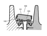
- FIG. 12 shows a conventional rotating partition described in Patent Document 1.
- a conventional rotating partition 100 is configured by providing a heat insulating material 103 made of polystyrene foam between a partition plate 101 serving as a storage chamber side outer member and a partition frame 102 serving as an outside air side outer member.
- the conventional refrigerator as described above can suppress heat from entering from the outside air into the refrigerator compartment due to the heat insulating property of the rotating partition, but since the heat insulating material made of polystyrene foam is used, the heat insulating property is improved. There remains room for.
- the sealing property of the outer member constituting the rotating partition is poor. And leakage of foam insulation.
- the foam insulation and the outer member constituting the rotating partition are in close contact with each other, and the foam insulation due to the temperature difference between the outside and inside the refrigerator when the refrigerator body is installed after the foam insulation is filled and foamed. There is a problem that partial contraction occurs, and warping or deformation occurs in the rotating partition.
- the present disclosure has been made in view of such a conventional problem, and provides a refrigerator that has high heat insulation, high energy saving, and can suppress deformation of a rotating partition.
- a refrigerator according to an example of an embodiment of the present disclosure includes a refrigerator main body, a refrigerator compartment provided in the refrigerator main body, a double door that opens and closes the refrigerator compartment, and left and right doors of the double door.
- a rotating partition provided at one of the ends.
- the rotating partition includes a storage chamber side outer member and an outside air side outer member.
- the rotating partition is configured by filling a foam heat insulating material between the storage chamber side outer member and the outside air side outer member via an interposed member.
- the heat insulating property of the rotating partition can be improved, and the heat intrusion of outside air can be effectively suppressed.
- the interposition member provided between the storage chamber side outer member and the outside air side outer member reduces the adhesive strength between the foamed heat insulating material and the storage chamber side outer member and the outer air side outer member constituting the rotating partition.
- warpage, deformation, and the like due to the cooling temperature difference of the rotating partition can be suppressed. Thereby, the refrigerator with improved energy saving and reliability can be provided.
- the interposition member may be configured with a soft bag member.
- the adhesive strength between the foam heat insulating material, the storage chamber side outer member and the outside air side outer member constituting the rotary partition body is reduced without hindering the filling property of the foam heat insulating material into the rotary partition body. It is possible to relieve the warpage and deformation due to the temperature difference of the rotating partition.
- the interposed member may have an opening hole for injecting foam heat insulating material and an opening hole for venting air.
- the storage chamber side outer member may have an injection hole for injecting foam heat insulating material and an air vent hole for venting air.
- the refrigerator according to an example of the embodiment of the present disclosure may further include a molded heat insulating member at an end portion in the longitudinal direction inside the rotary partition.
- the portion having a complicated structure can enhance the filling property of the foam heat insulating material into the rotating partition while ensuring the heat insulating property with the molded heat insulating member.
- the refrigerator according to an example of the embodiment of the present disclosure may further include a buffer sheet on the outer surface of the storage chamber side outer member.
- the injection hole and the air vent hole may be closed with a buffer sheet.
- FIG. 1 is a perspective view of a refrigerator according to an example of an embodiment of the present disclosure.
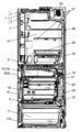
- FIG. 2 is a longitudinal sectional view of a refrigerator according to an example of the embodiment of the present disclosure.
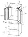
- FIG. 3 is a perspective view of a refrigerator according to an example of the embodiment of the present disclosure in a state where the double doors are opened.
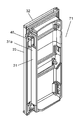
- FIG. 4 is a perspective view of one of the left and right doors of the double doors of the refrigerator according to an example of the embodiment of the present disclosure.
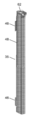
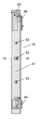
- FIG. 5A is an external perspective view of a rotary partition provided in a double door of a refrigerator according to an example of an embodiment of the present disclosure.
- FIG. 5B is a rear view of the rotating partition according to an example of the embodiment of the present disclosure.
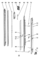
- FIG. 6 is an exploded perspective view of a rotating partition provided in a double door of a refrigerator according to an example of the embodiment of the present disclosure.
- FIG. 7 is an exploded perspective view of the rotating partition provided in the double door of the refrigerator according to an example of the embodiment of the present disclosure as seen from another viewpoint.
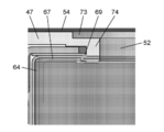
- FIG. 8 is a cross-sectional view of the vicinity of the foam heat insulating material injection hole of the rotary partition provided in the double door of the refrigerator according to an example of the embodiment of the present disclosure.
- FIG. 9 is an enlarged view of a portion B in FIG. 8 illustrating a rotary partition provided in a double door of the refrigerator according to an example of the embodiment of the present disclosure.
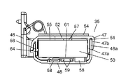
- FIG. 10 is a cross-sectional view taken along line 10-10 of FIG.
- FIG. 11A is a cross-sectional view of another example of the rotating partition portion provided in the double door of the refrigerator according to an example of the embodiment of the present disclosure.
- FIG. 11B is a cross-sectional view of still another example according to the example of the embodiment of the present disclosure.
- FIG. 12 is a cross-sectional view of a main part of a conventional double door of a refrigerator.
- FIG. 1 is a perspective view of a refrigerator according to an example of an embodiment of the present disclosure
- FIG. 2 is a longitudinal sectional view of a refrigerator according to an example of an embodiment of the present disclosure
- FIG. 3 is an embodiment of the embodiment of the present disclosure. It is a perspective view of the state by which the double doors of the refrigerator of the refrigerator by an example were opened.
- 4 is a perspective view of one of the left and right doors of the double door of the refrigerator according to an example of the embodiment of the present disclosure
- FIG. 5A is provided in the double door of the refrigerator according to the example of the embodiment of the present disclosure.
- FIG. 5B is an external perspective view of the rotating partition
- FIG. 5B is a rear view of the rotating partition according to an example of the embodiment of the present disclosure.
- 6 is an exploded perspective view of a rotary partition provided in a double door of a refrigerator according to an example of an embodiment of the present disclosure
- FIG. 7 is provided in a double door of a refrigerator according to an example of an embodiment of the present disclosure.
- FIG. 8 is an exploded perspective view of another rotary partition viewed from another viewpoint, and FIG. 8 is a vicinity of a foam heat insulating material injection hole of the rotary partition provided in the double door of the refrigerator according to an example of the embodiment of the present disclosure
- FIG. 9 is an enlarged view of part B of FIG.
- FIG. 8 showing a rotary partition provided in a double door of a refrigerator according to an example of the embodiment of the present disclosure
- FIG. 10 is a cross-sectional view taken along line 10-10 of FIG. 5B
- FIG. FIG. 11A is a cross-sectional view of another example of a rotating partition provided in a double door of a refrigerator according to an example of an embodiment of the present disclosure
- FIG. 11B is a refrigerator according to an example of an embodiment of the present disclosure. It is sectional drawing of other example of these.
- Refrigerator 200 includes a refrigerator main body 1 having an open front surface.
- the refrigerator body 1 includes a metal outer box 2, an inner box 3 made of hard resin, and a foam heat insulating material 4 that is foam-filled between the outer box 2 and the inner box 3.
- the refrigerator body 1 includes a plurality of storage rooms formed by partitioning the interior of the refrigerator body 1 with partition plates 5 and 6.
- Each storage room of the refrigerator main body 1 is provided with a double door 7 and drawer type doors 8, 9, 170, 11 that employ the same heat insulation structure as the refrigerator main body 1, and each storage room opens and closes. It is configured to be free.
- the plurality of storage chambers formed in the refrigerator main body 1 includes an uppermost refrigeration chamber 14, a switching chamber 15 provided below the refrigeration chamber 14 and a temperature-switchable switching chamber 15, and an ice making chamber 16 provided beside the chamber.
- the freezing room 18 provided under the switching room 15 and the ice making room 16 and the lowermost vegetable room 17 are provided.
- a cooling chamber 19 is provided on the back surface of the freezing chamber 18 of the refrigerator body 1.
- the cooling chamber 19 is provided with a cooler 20 that generates cool air and a cooling fan 21 that supplies the cool air to each of a plurality of storage chambers.
- a defrosting section 22 hereinafter referred to as a glass tube heater 22
- a glass tube heater 22 constituted by a glass tube heater or the like is provided below the cooler 20.
- a compressor 23 In the cooler 20, a compressor 23, a condenser (not shown), a heat radiating pipe (not shown), and a capillary tube (not shown) are annularly connected to form a refrigeration cycle. Yes.
- the refrigerator 200 is cooled by the circulation of the refrigerant compressed by the compressor 23.
- cooling fan 21 is provided above the cooler 20.
- the cooling fan 21 is connected to the downstream side of the cooling fan 21 via the refrigerator compartment duct 24, the freezer compartment duct 25, and the vegetable compartment duct (not shown), the refrigerator compartment 14, the freezer compartment 18, and the vegetable compartment.
- the cool air is supplied to 17 etc., and each of these chambers is cooled.
- the refrigerator compartment 14 is located in the uppermost part of the refrigerator main body 1, and as shown in FIG. 2, a plurality of shelf boards 27 are detachably provided, and the refrigerator compartment space is partitioned into a plurality of upper and lower spaces. .
- the refrigerator compartment 14 has two low-temperature storage compartments, for example, a partial freezer compartment 28 and a chilled compartment 29, which are stacked in two upper and lower stages.
- the temperature of the refrigerator compartment 14 is set so that it is cooled to a temperature that does not freeze, for example, 1 to 5 ° C.
- the temperature of the partial freezer chamber 28 in the refrigerator compartment 14 is set to be cooled to a temperature suitable for micro freezing storage, for example, ⁇ 2 ° C. to ⁇ 3 ° C.
- the chilled chamber 29 is set to a temperature that is lower than the refrigerated chamber 14 and is cooled to a temperature slightly higher than the partial freezer chamber 28, for example, a temperature around 1 ° C.
- the door of the refrigerating chamber 14 includes a double door 7 that includes a first door 71 and a second door 72.
- the first door 71 and the second door 72 are pivotally supported by the refrigerator main body 1 so as to be rotatable by the door hinge 13.
- the first door 71 and the second door 72 are made of a resin door inner frame 31, a door outer frame 32 made of resin like the door inner frame 31, and a glass plate constituting the door surface.
- a space portion surrounded by a transparent exterior plate such as a door is filled with a foam insulation material for doors such as hard foam urethane.
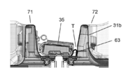
- One of the left and right doors of the double door 7 occurs when the double door 7 is closed on the free end side of the first door 71 having a narrow left and right width.
- a strip-like long and narrow rotating partition 35 that closes a gap between the door end surfaces of the first door 71 and the second door 72 is provided.
- the second door 72 having a wide left and right width, as shown in FIG. 36 is provided.
- a door switch that detects opening / closing of the door using the first door 71 and the second door 72 is incorporated in the upper part of the double door 7, for example.
- the rotary partition 35 is provided in the first door 71 of the double doors 7 in the present embodiment. Specifically, as shown in FIG. 4, the upper and lower portions of the rotary partition 35 are pivotally supported on the inner surface of the first door inner frame 31 a of the first door 71 by the hinge member 46. It is configured to rotate in conjunction with the opening and closing of the.
- the rotating partition 35 includes a storage chamber side outer member 47 and an outside air side outer member 48 as shown in FIG.
- the rotating partition 35 is formed in a hollow shape by fitting the opening portion of the storage chamber side outer member 47 and the opening portion of the outside air side outer member 48.
- the rotary partition 35 has a molded cut portion thermal material 49 (see FIGS. 6 and 7) made of expanded polystyrene at the upper end portion of the hollow portion.
- the rotating partition 35 is configured by filling the remaining most of the hollow portion with a foaming heat insulating material 50 for rotating partition such as urethane foam.
- the rotary partition 35 is a foam heat insulation for the rotary partition via a soft bag member 64 as an interposed member between the storage chamber side outer member 47 and the outside air side outer member 48 constituting the outer shell of the rotary partition 35.
- the material 50 is filled.
- the storage chamber side outer member 47 and the outside air side outer member 48 are both formed of a resin having low thermal conductivity. As shown in FIG. 10 and the like, the storage chamber side outer member 47 and the outside air side outer member 48 have an opening edge of one of them (in this embodiment, the storage chamber side outer member 47), the inner wall 47a and the outer wall. It is configured to have a double wall consisting of 47b. In the concave groove 51 between the inner wall 47a and the outer wall 47b of the double wall, the opening edge portion 48a of the other of the storage chamber side outer member 47 and the outer air side outer member 48 (in this embodiment, the outer air side outer member 48) is fitted. The storage chamber side outer member 47 and the outside air side outer member 48 are combined with each other. The height of the inner wall 47a (the length of the portion protruding from the flat portion of the storage chamber side outer member 47 toward the outside air side) is set to be higher than the height of the outer wall 47b.
- the storage chamber side outer member 47 is formed with an injection hole 52 for injecting urethane foam at a substantially central portion in the longitudinal direction, and in the vicinity of the end in the longitudinal direction, An air vent hole 53 is formed.
- a metal rotating partition reinforcing plate 55 is provided on the inner surface of the storage chamber side outer member 47.
- the rotating partition reinforcing plate 55 is fixed to the inner surface of the storage chamber side outer member 47 by claws 56 as shown in FIG.
- a plurality of holes 57 are dispersedly formed in the rotary partition reinforcing plate 55 over the longitudinal direction.
- the rotating partition reinforcing plate 55 includes a hole 66 at a portion facing the injection hole 52 provided in the storage chamber side outer member 47.
- the rotating partition reinforcing plate 55 has a hole 57 facing the air vent hole 53.
- the rotating partition 35 has a ring-shaped seal form 69 between the injection hole 52 of the storage chamber side outer member 47 and the hole 66 of the rotating partition reinforcing plate 55. . Further, the rotary partition 35 has a rectangular seal foam 70 between the air vent hole 53 and the hole 57. The storage chamber side outer member 47 and the rotating partition reinforcing plate 55 are fixed by claws 56 (see FIG. 10).
- the soft bag member 64 interposed in the space between the storage chamber side outer member 47 and the outside air side outer member 48 that constitutes the outer shell of the rotary partition 35 has a storage chamber side outer member 47 as shown in FIG.
- An opening hole 65 is provided so as to face the injection hole 52 and the hole 66 of the rotary partition reinforcing plate 55.
- the flexible bag member 64 has a rotary partition reinforcing plate 55 interposed between a hole 66 of the rotating partition reinforcing plate 55 and an opening hole 65 of the soft bag member 64 via a double-sided adhesive 67. Fixed to. Further, the vicinity of the end portion of the soft bag member 64 is also fixed to the rotary partition reinforcing plate 55 via the double-sided adhesive 68.
- the double-sided adhesive 67 has a gap at the center.
- the soft bag member 64 is provided with an opening hole for venting air at its end. Unnecessary air at the time of filling and foaming of the foaming insulating material 50 for the rotating partition is discharged from the opening hole for venting the flexible bag member 64, and from the air venting hole 53 of the storage chamber side outer member 47 through the seal foam 70. Unnecessary air is discharged to the outside.
- the injection hole 52 formed in the storage chamber side outer member 47 includes a stepped portion 73 that is recessed from the flat portion side to the inner space side of the storage chamber side outer member 47.
- the injection hole 52 has a flange portion 74 formed inside from the stepped portion 73.
- the urethane foam remaining in the vicinity of the injection hole 52 after injection of the urethane foam can be absorbed by the stepped portion 73 that is recessed toward the internal space, and the buffer sheet 54 that closes the air vent hole 53 is surely secured. Can be attached in a flat shape.
- the air vent hole 53 may include a stepped portion that is recessed from the flat surface side of the storage chamber side outer member 47 to the inner space side.
- a rotary partition magnet 58 (hereinafter, simply referred to as an inner peripheral surface gasket of the first door 71 and the second door 72) And a heater 59 for preventing condensation.
- the dew condensation prevention heater 59 is wired in the rotary partition 35 through the shaft support 46a (see FIG. 7) of the upper hinge member 46.
- a cylindrical member 60 is fitted on the shaft support 46a.
- the tubular member 60 has a length up to the middle of the upper side in the vertical direction of the molded heat insulating member 49 made of foamed polystyrene. That is, the cylindrical member 60 has a length shorter than the length of the molded heat insulating member 49 in the vertical direction.
- the dew condensation prevention heater 59 is wired through the tubular member 60 to the foam heat insulating material filling region.
- the dew condensation prevention heater 59 and the rotating partition magnet 58 are attached in advance to the inner surface of the outside air side outer member 48, which is a space filled with the foaming heat insulating material 50 for the rotating partition, with a tape 61 (see FIG. 10). It is fixed. In the present embodiment, almost the entire inner surface of the outside air-side outer member 48 is covered with the tape 61.
- the upper end portion of the rotary partition 35 is covered with a cap 62 (see FIG. 6), and the lower end portion is closed by fitting the lower opening side of the storage chamber side outer member 47 and the lower opening side of the outside air side outer member 48. Has been.
- the foamed heat insulating material 50 for the rotary partition is filled and foamed inside the rotary partition 35, the elasticity is set so that the injection hole 52 and the air vent hole 53 are closed on the side of the storage chamber of the storage chamber side outer member 47.
- a buffer sheet 54 is attached.
- the refrigerant is compressed by the compressor 23 constituting the refrigeration cycle in the cooler 20 (see FIG. 2).
- the compressed refrigerant is radiated by the condenser and depressurized by the capillary tube.
- the cold air generated by the cooler 20 is supplied from the cooling fan 21 to the refrigerator compartment 14, the switching room 15, the ice making room 16, the vegetable compartment 17, and the freezer compartment 18 in the refrigerator main body 1 through the duct. Is cooled to a predetermined temperature.
- the door of the refrigerator compartment 14 is composed of a double door 7 comprising a first door 71 and a second door 72.
- the first door 71 and the second door 72 are pivotally supported on the refrigerator body 1 by the door hinge 13 so as to be rotatable.
- the rotary partition 35 pivotally supported by the first door 71 of the double door 7 of the refrigerator 200 is an interposed member between the storage chamber side outer member 47 and the outside air side outer member 48.
- the foaming heat insulating material 50 for a rotating partition is filled through a certain soft bag member 64.
- the rotating partition 35 is a foaming heat insulating material for the rotating partition via the soft bag member 64 that is an interposed member between the storage chamber side outer member 47 and the outside air side outer member 48. 50 is filled.
- a soft bag member 64 which is an interposed member, is disposed between the storage chamber side outer member 47 and the outside air side outer member 48.
- a ring-shaped seal foam 69 is arranged between the injection hole 52 of the storage chamber side outer member 47 and the hole 66 of the rotating partition reinforcing plate 55. Further, a rectangular seal foam 70 is disposed between the air vent hole 53 and the hole 57.
- the storage chamber side outer member 47 and the rotating partition reinforcing plate 55 are fixed by claws 56 (see FIG. 10).
- the soft bag member 64 interposed in the space between the storage chamber side outer member 47 and the outside air side outer member 48 that constitutes the outer shell of the rotary partition 35 is connected to the injection hole 52 and the rotation of the storage chamber side outer member 47.
- An opening hole 65 is provided opposite to the hole 66 of the partition reinforcing plate 55.
- the soft bag member 64 is fixed to the rotary partition reinforcing plate 55 via a double-sided adhesive 67 between the hole 66 of the rotary partition reinforcing plate 55 and the opening hole 65 of the soft bag member 64.
- the upper and lower portions of the rotary partition 35 are pivotally connected to the first door 71 by a hinge member 46.
- a molded heat insulating member 49 made of polystyrene foam is provided at the installation portion of the hinge member 46 of the rotary partition 35. Accordingly, the vicinity of the shaft support portion of the hinge member 46 and the harness connection portion of the condensation prevention heater 59 having a complicated structure is configured by the molded heat insulating member 49, so the storage chamber side outer member 47 and the outside air side
- the space between the outer member 48 can be a simple structure.
- the soft bag member 64 can be made into a simple rectangular shape. With such a configuration, it is possible to eliminate leakage and insufficient filling of the foaming heat insulating material 50 for the rotating partition near the hinge member 46. Further, with such a configuration, the rotation operation of the rotary partition 35 can be stabilized.
- the wiring of the heater 59 for preventing condensation can freely move such as expansion and contraction in the tubular member 60, and even if the foaming heat insulating material 50 for the rotating partition is filled, It is possible to prevent disconnection due to torsion or the like of the condensation prevention heater 59.
- the rotary partition magnet 58 is attached to the inner surface of the outside air side outer member 48, and the surface of the rotary partition magnet 58 is Is covered with tape 61 (see FIG. 10).
- the foamed heat insulating material 50 for the rotating partition can be reliably prevented from entering between the outside air side outer member 48 and the rotating partition magnet 58. .
- the magnetic force fall by penetration of a foam heat insulating material can be prevented.
- the refrigerating chamber 14 can be reliably sealed by the rotating partition 35, and the entry of outside heat can be more effectively suppressed to improve energy saving. .
- the rotating partition 35 is provided with a metal rotating partition reinforcing plate 55 on the inner surface of the storage chamber side outer member 47.
- the foaming heat insulating material 50 for the rotating partition in the rotating partition 35 is in contact with the rotating partition reinforcing plate 55 through the soft bag member 64.
- the rotating partition foam insulating material 50 and the rotating partition reinforcing plate 55 are in indirect contact with each other, and the rotating partition reinforcing plate 55 is generated by thermal contraction of the rotating partition foam insulating material 50. The direct deformation of can be suppressed.
- the rotating partition reinforcing plate 55 includes a plurality of holes 57 in the longitudinal direction including holes facing the injection holes 52 and the air vent holes 53 of the foaming heat insulating material for the rotating partition provided in the storage chamber side outer member 47. Is formed. With such a configuration, the rotating partition reinforcing plate can be injected from the injection hole 52 provided in the storage chamber side outer member 47 while allowing the foam insulating material 50 for the rotating partition to be filled into the soft bag member 64 to be injected. 55 can be reduced in weight. Thereby, the rotating partition 35 itself can be reduced in weight, the rotation operation of the rotating partition 35 can be stabilized, and the inertial force of the rotating partition 35 generated during the rotation can be reduced, so that the collision sound and the like can be further reduced. .
- the rotary partition 35 has a square shape. With such a configuration, a good heat insulating effect can be exhibited over the entire left and right regions, and the heat insulating effect can be enhanced.
- the rotating partition 35 has a buffer sheet 54 mounted on the side surface of the storage chamber side outer member 47 (see FIG. 10).
- the buffer sheet 54 is provided over the longitudinal direction of the storage chamber side surface of the storage chamber side outer member 47.
- the injection hole 52 and the air vent hole 53 can be covered and the storage chamber side surface of the storage chamber side outer member 47 can be made to have a clean appearance.
- rotation is achieved by providing a flexible auxiliary seal member 63 between the rotary free end side of the rotary partition 35 and the inner vertical wall of the second door 72.
- a gap T generated by the rotation locus of the partition 35 can be closed by the auxiliary seal member 63.
- a soft bag member 64 is used as an example of an intervening member interposed between the storage chamber side outer member 47 and the outside air side outer member 48 that constitutes the outer shell of the rotary partition 35.
- the interposition member is not limited to this.
- the magnet 58 is embedded in the rotary partition 35. This is because the storage chamber side outer member 47 and the outdoor air side outer member 48 have low thermal conductivity. It is assumed that it is made of resin. That is, the magnet 58 is embedded in the rotary partition 35 so that the gasket having the door-side magnet is reliably attracted to the rotary partition 35 and the sealing property is secured.
- a magnetized iron plate or the like may be used as the storage chamber side outer member 47 without embedding the magnet 58 in the rotating partition 35.
- an arrangement space portion of the magnet 58 inside the rotary partition 35 can be filled with the foaming heat insulating material 50 for the rotary partition via the soft bag member 64.
- strength of the rotary partition 35 can be raised.
- the rotating partition reinforcing plate 55 provided in the storage chamber side outer member 47 can be eliminated or thinned, and the heat insulation, strength and cost can be reduced. The optimal balance can be achieved.
- the example in which the molded heat insulating member 49 made of foamed polystyrene is provided in the vicinity of the hinge member 46 at the upper end portion of the rotary partition 35 has been described, but is not limited thereto.
- the specification is such that almost all the interior of the rotary partition 35 including the vicinity of the hinge members 46 at the upper and lower ends of the rotary partition 35 is filled with the foam insulation 50 for the rotary partition via the soft bag member 64. Good.
- the present disclosure provides a refrigerator that can enhance the heat insulating property of the rotating partition and can suppress warping, deformation, and the like due to the temperature difference of the rotating partition. Therefore, the present invention can be widely applied to refrigerators, cooling devices, and the like of various types and sizes such as home use and business use provided with a rotating partition.
Landscapes
- Engineering & Computer Science (AREA)
- Chemical & Material Sciences (AREA)
- Combustion & Propulsion (AREA)
- Physics & Mathematics (AREA)
- Mechanical Engineering (AREA)
- Thermal Sciences (AREA)
- General Engineering & Computer Science (AREA)
- Refrigerator Housings (AREA)
Applications Claiming Priority (2)
| Application Number | Priority Date | Filing Date | Title |
|---|---|---|---|
| JP2016-214901 | 2016-11-02 | ||
| JP2016214901A JP7038274B2 (ja) | 2016-11-02 | 2016-11-02 | 冷蔵庫 |
Publications (1)
| Publication Number | Publication Date |
|---|---|
| WO2018084037A1 true WO2018084037A1 (ja) | 2018-05-11 |
Family
ID=62076807
Family Applications (1)
| Application Number | Title | Priority Date | Filing Date |
|---|---|---|---|
| PCT/JP2017/038440 Ceased WO2018084037A1 (ja) | 2016-11-02 | 2017-10-25 | 冷蔵庫 |
Country Status (2)
| Country | Link |
|---|---|
| JP (1) | JP7038274B2 (enExample) |
| WO (1) | WO2018084037A1 (enExample) |
Citations (6)
| Publication number | Priority date | Publication date | Assignee | Title |
|---|---|---|---|---|
| JPS4613552B1 (enExample) * | 1968-09-11 | 1971-04-10 | ||
| JPS5921973A (ja) * | 1982-07-28 | 1984-02-04 | 株式会社東芝 | 冷蔵庫用断熱扉の製造方法 |
| JPS646683A (en) * | 1987-06-26 | 1989-01-11 | Matsushita Refrigeration | Heat-insulating box body |
| JP2011112290A (ja) * | 2009-11-27 | 2011-06-09 | Panasonic Corp | 冷蔵庫 |
| WO2013046581A1 (ja) * | 2011-09-29 | 2013-04-04 | パナソニック株式会社 | 冷蔵庫 |
| JP2015215153A (ja) * | 2014-04-24 | 2015-12-03 | パナソニックIpマネジメント株式会社 | 冷蔵庫 |
-
2016
- 2016-11-02 JP JP2016214901A patent/JP7038274B2/ja not_active Expired - Fee Related
-
2017
- 2017-10-25 WO PCT/JP2017/038440 patent/WO2018084037A1/ja not_active Ceased
Patent Citations (6)
| Publication number | Priority date | Publication date | Assignee | Title |
|---|---|---|---|---|
| JPS4613552B1 (enExample) * | 1968-09-11 | 1971-04-10 | ||
| JPS5921973A (ja) * | 1982-07-28 | 1984-02-04 | 株式会社東芝 | 冷蔵庫用断熱扉の製造方法 |
| JPS646683A (en) * | 1987-06-26 | 1989-01-11 | Matsushita Refrigeration | Heat-insulating box body |
| JP2011112290A (ja) * | 2009-11-27 | 2011-06-09 | Panasonic Corp | 冷蔵庫 |
| WO2013046581A1 (ja) * | 2011-09-29 | 2013-04-04 | パナソニック株式会社 | 冷蔵庫 |
| JP2015215153A (ja) * | 2014-04-24 | 2015-12-03 | パナソニックIpマネジメント株式会社 | 冷蔵庫 |
Also Published As
| Publication number | Publication date |
|---|---|
| JP7038274B2 (ja) | 2022-03-18 |
| JP2018071930A (ja) | 2018-05-10 |
Similar Documents
| Publication | Publication Date | Title |
|---|---|---|
| KR102186861B1 (ko) | 냉장고 | |
| US20140097733A1 (en) | Refrigerator and filler thereof | |
| JP5753379B2 (ja) | 冷却貯蔵庫の扉装置 | |
| JP6905856B2 (ja) | 冷蔵庫 | |
| JP7236610B2 (ja) | 冷蔵庫 | |
| JP2011174625A (ja) | 冷蔵庫 | |
| JP2011112290A (ja) | 冷蔵庫 | |
| JP4802954B2 (ja) | 冷蔵庫 | |
| JP2002364978A (ja) | 冷蔵庫 | |
| CN113348334A (zh) | 冰箱 | |
| JP5948601B2 (ja) | 冷蔵庫 | |
| JP2021025664A (ja) | 冷蔵庫 | |
| JP6748843B2 (ja) | 冷蔵庫 | |
| WO2018084037A1 (ja) | 冷蔵庫 | |
| JP2013185730A (ja) | 冷蔵庫 | |
| JP6937472B2 (ja) | 冷蔵庫 | |
| JP5380216B2 (ja) | 冷蔵庫 | |
| JP2008096008A (ja) | 冷蔵庫 | |
| JP2005180720A (ja) | 冷蔵庫 | |
| JP3823993B2 (ja) | 冷蔵庫 | |
| WO2018003549A1 (ja) | 冷蔵庫 | |
| JP2008002694A (ja) | 冷蔵庫 | |
| JP2013185732A (ja) | 冷蔵庫 | |
| JP7079063B2 (ja) | 冷蔵庫 | |
| JP5885934B2 (ja) | 冷蔵庫 |
Legal Events
| Date | Code | Title | Description |
|---|---|---|---|
| 121 | Ep: the epo has been informed by wipo that ep was designated in this application |
Ref document number: 17867037 Country of ref document: EP Kind code of ref document: A1 |
|
| NENP | Non-entry into the national phase |
Ref country code: DE |
|
| 122 | Ep: pct application non-entry in european phase |
Ref document number: 17867037 Country of ref document: EP Kind code of ref document: A1 |