WO2018079844A1 - 車両用駆動伝達装置 - Google Patents
車両用駆動伝達装置 Download PDFInfo
- Publication number
- WO2018079844A1 WO2018079844A1 PCT/JP2017/039371 JP2017039371W WO2018079844A1 WO 2018079844 A1 WO2018079844 A1 WO 2018079844A1 JP 2017039371 W JP2017039371 W JP 2017039371W WO 2018079844 A1 WO2018079844 A1 WO 2018079844A1
- Authority
- WO
- WIPO (PCT)
- Prior art keywords
- gear
- clutch
- rotating element
- rotating
- ratio
- Prior art date
- Legal status (The legal status is an assumption and is not a legal conclusion. Google has not performed a legal analysis and makes no representation as to the accuracy of the status listed.)
- Ceased
Links
Images



Classifications
-
- B—PERFORMING OPERATIONS; TRANSPORTING
- B60—VEHICLES IN GENERAL
- B60K—ARRANGEMENT OR MOUNTING OF PROPULSION UNITS OR OF TRANSMISSIONS IN VEHICLES; ARRANGEMENT OR MOUNTING OF PLURAL DIVERSE PRIME-MOVERS IN VEHICLES; AUXILIARY DRIVES FOR VEHICLES; INSTRUMENTATION OR DASHBOARDS FOR VEHICLES; ARRANGEMENTS IN CONNECTION WITH COOLING, AIR INTAKE, GAS EXHAUST OR FUEL SUPPLY OF PROPULSION UNITS IN VEHICLES
- B60K6/00—Arrangement or mounting of plural diverse prime-movers for mutual or common propulsion, e.g. hybrid propulsion systems comprising electric motors and internal combustion engines
- B60K6/20—Arrangement or mounting of plural diverse prime-movers for mutual or common propulsion, e.g. hybrid propulsion systems comprising electric motors and internal combustion engines the prime-movers consisting of electric motors and internal combustion engines, e.g. HEVs
- B60K6/22—Arrangement or mounting of plural diverse prime-movers for mutual or common propulsion, e.g. hybrid propulsion systems comprising electric motors and internal combustion engines the prime-movers consisting of electric motors and internal combustion engines, e.g. HEVs characterised by apparatus, components or means specially adapted for HEVs
- B60K6/40—Arrangement or mounting of plural diverse prime-movers for mutual or common propulsion, e.g. hybrid propulsion systems comprising electric motors and internal combustion engines the prime-movers consisting of electric motors and internal combustion engines, e.g. HEVs characterised by apparatus, components or means specially adapted for HEVs characterised by the assembly or relative disposition of components
-
- B—PERFORMING OPERATIONS; TRANSPORTING
- B60—VEHICLES IN GENERAL
- B60K—ARRANGEMENT OR MOUNTING OF PROPULSION UNITS OR OF TRANSMISSIONS IN VEHICLES; ARRANGEMENT OR MOUNTING OF PLURAL DIVERSE PRIME-MOVERS IN VEHICLES; AUXILIARY DRIVES FOR VEHICLES; INSTRUMENTATION OR DASHBOARDS FOR VEHICLES; ARRANGEMENTS IN CONNECTION WITH COOLING, AIR INTAKE, GAS EXHAUST OR FUEL SUPPLY OF PROPULSION UNITS IN VEHICLES
- B60K6/00—Arrangement or mounting of plural diverse prime-movers for mutual or common propulsion, e.g. hybrid propulsion systems comprising electric motors and internal combustion engines
- B60K6/20—Arrangement or mounting of plural diverse prime-movers for mutual or common propulsion, e.g. hybrid propulsion systems comprising electric motors and internal combustion engines the prime-movers consisting of electric motors and internal combustion engines, e.g. HEVs
- B60K6/42—Arrangement or mounting of plural diverse prime-movers for mutual or common propulsion, e.g. hybrid propulsion systems comprising electric motors and internal combustion engines the prime-movers consisting of electric motors and internal combustion engines, e.g. HEVs characterised by the architecture of the hybrid electric vehicle
- B60K6/48—Parallel type
-
- B—PERFORMING OPERATIONS; TRANSPORTING
- B60—VEHICLES IN GENERAL
- B60K—ARRANGEMENT OR MOUNTING OF PROPULSION UNITS OR OF TRANSMISSIONS IN VEHICLES; ARRANGEMENT OR MOUNTING OF PLURAL DIVERSE PRIME-MOVERS IN VEHICLES; AUXILIARY DRIVES FOR VEHICLES; INSTRUMENTATION OR DASHBOARDS FOR VEHICLES; ARRANGEMENTS IN CONNECTION WITH COOLING, AIR INTAKE, GAS EXHAUST OR FUEL SUPPLY OF PROPULSION UNITS IN VEHICLES
- B60K6/00—Arrangement or mounting of plural diverse prime-movers for mutual or common propulsion, e.g. hybrid propulsion systems comprising electric motors and internal combustion engines
- B60K6/20—Arrangement or mounting of plural diverse prime-movers for mutual or common propulsion, e.g. hybrid propulsion systems comprising electric motors and internal combustion engines the prime-movers consisting of electric motors and internal combustion engines, e.g. HEVs
- B60K6/50—Architecture of the driveline characterised by arrangement or kind of transmission units
- B60K6/54—Transmission for changing ratio
- B60K6/547—Transmission for changing ratio the transmission being a stepped gearing
-
- F—MECHANICAL ENGINEERING; LIGHTING; HEATING; WEAPONS; BLASTING
- F16—ENGINEERING ELEMENTS AND UNITS; GENERAL MEASURES FOR PRODUCING AND MAINTAINING EFFECTIVE FUNCTIONING OF MACHINES OR INSTALLATIONS; THERMAL INSULATION IN GENERAL
- F16H—GEARING
- F16H3/00—Toothed gearings for conveying rotary motion with variable gear ratio or for reversing rotary motion
- F16H3/02—Toothed gearings for conveying rotary motion with variable gear ratio or for reversing rotary motion without gears having orbital motion
- F16H3/08—Toothed gearings for conveying rotary motion with variable gear ratio or for reversing rotary motion without gears having orbital motion exclusively or essentially with continuously meshing gears, that can be disengaged from their shafts
- F16H3/087—Toothed gearings for conveying rotary motion with variable gear ratio or for reversing rotary motion without gears having orbital motion exclusively or essentially with continuously meshing gears, that can be disengaged from their shafts characterised by the disposition of the gears
- F16H3/093—Toothed gearings for conveying rotary motion with variable gear ratio or for reversing rotary motion without gears having orbital motion exclusively or essentially with continuously meshing gears, that can be disengaged from their shafts characterised by the disposition of the gears with two or more countershafts
-
- F—MECHANICAL ENGINEERING; LIGHTING; HEATING; WEAPONS; BLASTING
- F16—ENGINEERING ELEMENTS AND UNITS; GENERAL MEASURES FOR PRODUCING AND MAINTAINING EFFECTIVE FUNCTIONING OF MACHINES OR INSTALLATIONS; THERMAL INSULATION IN GENERAL
- F16H—GEARING
- F16H3/00—Toothed gearings for conveying rotary motion with variable gear ratio or for reversing rotary motion
- F16H3/44—Toothed gearings for conveying rotary motion with variable gear ratio or for reversing rotary motion using gears having orbital motion
- F16H3/62—Gearings having three or more central gears
- F16H3/66—Gearings having three or more central gears composed of a number of gear trains without drive passing from one train to another
-
- F—MECHANICAL ENGINEERING; LIGHTING; HEATING; WEAPONS; BLASTING
- F16—ENGINEERING ELEMENTS AND UNITS; GENERAL MEASURES FOR PRODUCING AND MAINTAINING EFFECTIVE FUNCTIONING OF MACHINES OR INSTALLATIONS; THERMAL INSULATION IN GENERAL
- F16H—GEARING
- F16H3/00—Toothed gearings for conveying rotary motion with variable gear ratio or for reversing rotary motion
- F16H3/44—Toothed gearings for conveying rotary motion with variable gear ratio or for reversing rotary motion using gears having orbital motion
- F16H3/72—Toothed gearings for conveying rotary motion with variable gear ratio or for reversing rotary motion using gears having orbital motion with a secondary drive, e.g. regulating motor, in order to vary speed continuously
-
- Y—GENERAL TAGGING OF NEW TECHNOLOGICAL DEVELOPMENTS; GENERAL TAGGING OF CROSS-SECTIONAL TECHNOLOGIES SPANNING OVER SEVERAL SECTIONS OF THE IPC; TECHNICAL SUBJECTS COVERED BY FORMER USPC CROSS-REFERENCE ART COLLECTIONS [XRACs] AND DIGESTS
- Y02—TECHNOLOGIES OR APPLICATIONS FOR MITIGATION OR ADAPTATION AGAINST CLIMATE CHANGE
- Y02T—CLIMATE CHANGE MITIGATION TECHNOLOGIES RELATED TO TRANSPORTATION
- Y02T10/00—Road transport of goods or passengers
- Y02T10/60—Other road transportation technologies with climate change mitigation effect
- Y02T10/62—Hybrid vehicles
Definitions
- the present invention relates to a vehicle drive transmission device.
- a vehicle drive transmission device including an input member that is drivingly connected to an internal combustion engine, an output member that is drivingly connected to a wheel, and an automatic transmission that changes the rotation of the input member and transmits the rotation to the output member is known. ing.
- An example of a vehicle drive transmission device having such a configuration is disclosed in Japanese Patent Publication No. 2009-541474 (Patent Document 1).
- Patent Document 1 Japanese Patent Publication No. 2009-541474
- reference numerals shown in parentheses in the description of the background art are those of Patent Document 1.
- Patent Document 1 describes a vehicle drive transmission device provided with a dual clutch type automatic transmission.
- the automatic transmission includes a first planetary gear box (PG1) drivingly connected to the drive shaft (An) via the first clutch (K1), and a drive shaft via the second clutch (K2).
- a second planetary gear box (PG2) that is drivingly connected to (An).
- the automatic transmission alternately engages the first clutch (K1) and the second clutch (K2), thereby shifting the rotation of the drive shaft (An) and transmitting it to the driven shaft (Ab).
- the speed change mechanism is configured to switch alternately between the first planetary gear box (PG1) and the second planetary gear box (PG2).
- the first planetary gear box (PG1) and the second planetary gear box (PG2) have the same structure.
- a gear device is used. Therefore, the rotation element that is drivingly connected to the drive shaft (An) among the plurality of rotation elements included in the planetary gear box (PG1, PG2) is set as the input side rotation element, and the driven shaft (Ab) among the plurality of rotation elements.
- Rotational speed ratio between the input side rotational element and the output side rotational element of each gear stage formed in the planetary gear box (speed ratio in the planetary gear box) Is the same or similar between the two planetary gearboxes (PG1, PG2).
- the automatic transmission includes a first transmission mechanism that is drivingly connected to the input member via the first clutch and a second transmission mechanism that is drivingly connected to the input member via the second clutch. It is desired to realize a vehicle drive transmission device capable of setting the value of the gear ratio step to an appropriate value for each of the combinations of gears to be changed.
- a vehicle including an input member that is drivingly connected to an internal combustion engine, an output member that is drivingly connected to a wheel, and an automatic transmission that shifts the rotation of the input member and transmits the rotation to the output member.
- the first characteristic configuration of the drive transmission device for the vehicle is that the automatic transmission is drivingly connected to the input member via a first clutch and a first transmission mechanism that is drivingly connected to the input member via a first clutch.
- a first transmission mechanism, and each of the first transmission mechanism and the second transmission mechanism includes a planetary gear mechanism, the connection relationship of the planetary gear mechanisms of the first transmission mechanism, and the second transmission mechanism. Are different from each other in the planetary gear mechanism.
- the first transmission mechanism is formed by the first transmission mechanism as compared with the case where the connection relation of the planetary gear mechanism of the first transmission mechanism is the same as that of the planetary gear mechanism of the second transmission mechanism.
- the input / output rotational speed ratio of each shift stage (the rotational speed ratio between the rotational element drivingly connected to the input member in the first transmission mechanism and the rotational element drivingly connected to the output member of the first transmission mechanism)
- the input / output rotational speed ratio of each shift stage formed by the second transmission mechanism (a rotation element that is drivingly connected to the input member in the second transmission mechanism, and a rotation element that is drivingly connected to the output member in the second transmission mechanism) It is easy to make the rotation speed ratio between the two different from each other. As a result, it becomes easy to ensure a high degree of freedom in design of the ratio (speed ratio step) of the gear ratio between adjacent gear speeds, and the value of the gear ratio step is appropriately set for each combination of adjacent gear speeds. Can be a value.
- a vehicle including an input member that is drivingly connected to an internal combustion engine, an output member that is drivingly connected to a wheel, and an automatic transmission that changes the rotation of the input member and transmits the rotation to the output member.
- the automatic transmission is driven and connected to the input member via a first clutch and a first transmission mechanism connected to the input member via a first clutch.
- a second transmission mechanism wherein each of the first transmission mechanism and the second transmission mechanism includes a planetary gear mechanism, and the first transmission mechanism includes a plurality of shift speeds that can be formed by the automatic transmission.
- the second speed change mechanism forms an even number out of the plurality of shift speeds, and the ratio of the gear ratio between adjacent speed shifts toward the high speed speed side. It is in a small point.
- the torque fluctuation that is, the shift shock
- the value of the gear ratio step in each of the adjacent gear stage combinations can be set to an appropriate value from the viewpoint of the gear feeling.
- driving connection means a state where two rotating elements are connected so as to be able to transmit driving force.
- This concept includes a state where the two rotating elements are coupled so as to rotate integrally, and a state where the two rotating elements are coupled so as to be able to transmit the driving force via one or more transmission members.
- Such transmission members include various members (shafts, gear mechanisms, belts, chains, etc.) that transmit rotation at the same speed or at different speeds, and an engagement device that selectively transmits rotation and driving force. (Such as a friction engagement device or a meshing engagement device) may be included.
- a differential gear mechanism for each rotating element of a planetary gear mechanism, a differential gear mechanism, or a mechanism (such as a first transmission mechanism 41 or a second transmission mechanism 42 described later) configured using a planetary gear mechanism or a differential gear mechanism.
- drive connection refers to a state in which three or more rotation elements included in the mechanism are connected to each other without intervening other rotation elements.
- the “rotary electric machine” is used as a concept including any of a motor (electric motor), a generator (generator), and a motor / generator functioning as both a motor and a generator as necessary.
- overlapping when viewed in a certain direction means that when a virtual straight line parallel to the visual line direction is moved in each direction orthogonal to the virtual straight line, It means that the region where the virtual straight line intersects both of the two members exists at least in part.
- “overlapping in the radial direction” means that a region where the virtual straight line intersects both of the two members exists in at least a partial region in the circumferential direction.
- the “axial direction L” is defined based on the automatic transmission 4.
- the automatic transmission 4 includes a first transmission mechanism 41 disposed on the first axis A1 and a second axis A2 (an axis parallel to the first axis A1 and different from the first axis A1).
- a second speed change mechanism 42 disposed.
- a direction parallel to the first axis A1 and the second axis A2 is defined as an axial direction L. That is, the axial direction L is an axial direction common between the first axis A1 and the second axis A2.
- the first axial side L ⁇ b> 1 is a side where the first transmission mechanism 41 and the second transmission mechanism 42 are arranged with respect to the input gear mechanism 10 (or the input shaft 90) described later in the axial direction L. It is.
- the axial second side L2 is the side where the internal combustion engine 2 is arranged with respect to the input gear mechanism 10 (input shaft 90) in the axial direction L.
- the direction about each member in the following description represents the direction in the state in which they were assembled to the vehicle drive transmission device 1.
- the term regarding the direction, position, etc. about each member is a concept including the state which has the difference by the error which can be accept
- the vehicle drive transmission device 1 is mounted on a vehicle and is a device for transmitting the driving force of the driving force source of the wheel 9 to the wheel 9.
- the driving force source of the wheel 9 includes at least the internal combustion engine 2, and in this embodiment, includes the rotating electrical machine 3 in addition to the internal combustion engine 2.
- the vehicle drive transmission device 1 is mounted on a vehicle (hybrid vehicle) that includes both the internal combustion engine 2 and the rotating electrical machine 3 as driving force sources for the wheels 9.
- the driving force of the engine 2 and the rotating electrical machine 3 is configured to be transmitted to the wheels 9.
- the vehicle drive transmission device 1 of the present embodiment is configured as a drive transmission device for an FF (Front Engine Front Drive) vehicle.
- FF Front Engine Front Drive
- the vehicle drive transmission device 1 shifts and rotates the input shaft 90 that is drivingly connected to the internal combustion engine 2, the output member 91 that is drivingly connected to the wheels 9, and the rotation of the input shaft 90. And an automatic transmission 4 for transmission to the member 91.
- the vehicle drive transmission device 1 further includes a rotating electrical machine 3, a differential gear device 7, and a case 6.
- the case 6 accommodates at least the automatic transmission 4.
- the case 6 accommodates the rotating electrical machine 3 and the differential gear device 7 in addition to the automatic transmission 4.
- the input shaft 90 corresponds to an “input member”
- the case 6 corresponds to a “non-rotating member”.
- the internal combustion engine 2 is a prime mover (for example, a gasoline engine, a diesel engine, or the like) that is driven by combustion of fuel inside the engine to extract power.
- the input shaft 90 is drivingly connected to an output shaft (crankshaft or the like) of the internal combustion engine 2.
- the input shaft 90 is connected to rotate integrally with the output shaft of the internal combustion engine 2 or is drivingly connected to the output shaft of the internal combustion engine 2 via another member such as a damper.
- the differential gear device 7 distributes and transmits the rotation and torque input to the differential input gear 7a from the automatic transmission 4 side to the left and right output shafts 8 (that is, the left and right two wheels 9).
- the output shaft 8 is a shaft (drive shaft) that connects the differential gear device 7 and the wheel 9.
- the rotational driving force of the input shaft 90 is input to the automatic transmission 4, and the rotational driving force of the input shaft 90 shifted by the automatic transmission 4 is output from the automatic transmission 4 to the output member 91.
- the rotational driving force input to the output member 91 from the automatic transmission 4 side is input to the differential gear device 7.
- the differential input gear 7a is used as the output member 91 (functions as the output member 91), and the rotational driving force of the input shaft 90 that is shifted by the automatic transmission 4 is the differential gear. Directly input to the device 7 (differential input gear 7a).
- the rotating electrical machine 3 is used as a driving force source for the wheels 9.
- the output rotating member 3a of the rotating electrical machine 3 is drivingly connected to an input gear mechanism 10 described later.
- the output rotating member 3 a is an output gear for outputting torque of the rotating electrical machine 3.
- the rotating electrical machine 3 includes a stator that is fixed to the case 6 and a rotor that is rotatably supported with respect to the stator.
- An output rotating member 3a is connected to the rotor of the rotating electrical machine 3 so as to rotate integrally.
- the output rotating member 3a is connected to the rotor of the rotating electrical machine 3 by the rotor shaft 3b.
- the rotating electrical machine 3 is electrically connected to a power storage device (not shown) such as a battery or a capacitor, and is powered by power supplied from the power storage device, or the torque of the internal combustion engine 2 or the inertial force of the vehicle.
- the electric power generated by is supplied to the power storage device to be stored.
- the automatic transmission 4 is drivingly connected to the input shaft 90 via a first clutch C1 and a first transmission mechanism 41 that is drivingly connected to the input shaft 90 via a first clutch C1.
- the vehicle drive transmission device 1 includes an input gear mechanism 10 in a power transmission path between the input shaft 90 and each transmission mechanism (41, 42), and each of the first transmission mechanism 41 and the second transmission mechanism 42 is provided. The rotation of the input gear mechanism 10 is shifted and transmitted to the output member 91.
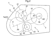
- the first transmission mechanism 41, the second transmission mechanism 42, the input gear mechanism 10, the differential gear device 7, and the rotating electrical machine 3 have five axes (first axis A1) parallel to each other.
- 2 shows the positional relationship of the components of the vehicle drive transmission device 1 as viewed in the axial direction L.
- the reference pitch circle is indicated by a one-dot chain line
- the outer diameter When the rotating electrical machine 3 is an inner rotor type, the outer peripheral surface of the stator is indicated by a solid line.
- the first transmission mechanism 41 is arranged on the first axis A1
- the second transmission mechanism 42 is arranged on the second axis A2
- the input gear mechanism 10 is arranged on the third axis A3.
- the moving gear device 7 is disposed on the fourth axis A4, and the rotating electrical machine 3 is disposed on the fifth axis A5.
- the rotating electrical machine 3 is disposed on a different axis from the input gear mechanism 10.
- the rotating electrical machine 3 is arranged on a separate axis from the first transmission mechanism 41 and the second transmission mechanism 42.
- the first axis A1 and the second axis A2 are line segments X (imaginary straight lines) connecting the fourth axis A4 and the fifth axis A5 when viewed in the axial direction L. They are arranged on opposite sides of each other.
- the third axis A3, the fifth axis A5, and the fourth axis A4, when viewed in the axial direction L, are a line segment Y (virtual straight line) connecting the first axis A1 and the second axis A2. ) are arranged on opposite sides of each other.
- a first driven gear 21 to be described later is disposed on the first axis A1 (that is, coaxially with the first transmission mechanism 41), and a second driven gear 22 to be described later is a second shaft. It is disposed on A2 (that is, coaxially with the second transmission mechanism 42).
- the second driven gear 22 is disposed at a position overlapping the first driven gear 21 when viewed in the radial direction of the first driven gear 21.
- the first driven gear 21 and the second driven gear 22 are arranged at the same position in the axial direction L.
- the first clutch C1 is disposed on the first shaft A1 (that is, coaxially with the first transmission mechanism 41), and the second clutch C2 is disposed on the second shaft A2 (that is, the first transmission mechanism 41).
- the second transmission mechanism 42 is disposed on the same axis).
- the 2nd clutch C2 is arrange
- the first clutch C1 and the second clutch C2 are arranged at the same position in the axial direction L. As shown in FIG.
- a first output gear 31, a first driven gear 21, a first clutch C1, and a first clutch, which will be described later, are sequentially arranged from the second axial side L2 on the first axis A1.
- the transmission mechanism 41 is arranged in this order, and the second output gear 32, the second driven gear 22, the second clutch C2, and the second transmission mechanism 42, which will be described later, are sequentially arranged from the second axial side L2 on the second axis A2.
- the output gears (31, 32), the driven gears (21, 22), the clutches (C1, C2), and the transmission mechanisms (41, 42) are arranged in this order from the second axial side L2.
- the input gear mechanism 10 is drivingly connected to the input shaft 90.
- the input gear mechanism 10 includes a common drive gear 13 that meshes with both the first driven gear 21 and the second driven gear 22, and the common driving gear 13 has a rotational driving force of the input shaft 90. Is transmitted.
- the vehicle drive transmission device 1 includes a seventh clutch C7 that connects or disconnects the input shaft 90 and the input gear mechanism 10 (common drive gear 13).
- the seventh clutch C7 is provided in a power transmission path between the input shaft 90 and the input gear mechanism 10 (common drive gear 13).
- the seventh clutch C7 is arranged coaxially with the common drive gear 13 on the second axial side L2 from the common drive gear 13.
- the output rotating member 3a of the rotating electrical machine 3 is drivingly connected to the common driving gear 13 without passing through the seventh clutch C7.
- the output rotating member 3a of the rotating electrical machine 3 is drivingly connected to the common driving gear 13 without passing through the first clutch C1 and the second clutch C2.
- the output rotation member 3 a of the rotating electrical machine 3 is engaged with the common drive gear 13. That is, the rotating electrical machine 3 is drivingly connected to the input shaft 90 via the input gear mechanism 10 (common drive gear 13) and the seventh clutch C7.
- the output rotating member 3a of the rotating electrical machine 3 is different from the first driven gear 21 and the second driven gear 22 in the circumferential direction (circumferential direction with the third axis A3 as a reference) at the input gear mechanism 10 (here, Meshes with the common drive gear 13). As described above, the output rotating member 3a of the rotating electrical machine 3 is disposed closer to the input shaft 90 than the first transmission mechanism 41 and the second transmission mechanism 42 in the power transmission path between the input shaft 90 and the output member 91. Connected to the member (in this embodiment, the common drive gear 13).
- the seventh clutch C7 transmits only the torque of the internal combustion engine 2 to the wheels 9 and transmits the torque of both the internal combustion engine 2 and the rotating electrical machine 3 to the wheels 9 when executing the internal combustion engine traveling mode in which the vehicle travels. It is controlled to be in an engaged state at the time of execution of the hybrid driving mode for driving the vehicle, and is controlled to be released at the time of execution of the electric driving mode for driving the vehicle by transmitting only the torque of the rotating electrical machine 3 to the wheels 9. . That is, the seventh clutch C7 is provided to disconnect the internal combustion engine 2 from the wheel 9 when the electric travel mode is executed, and the drag loss of the internal combustion engine 2 is disconnected by disconnecting the internal combustion engine 2 from the wheel 9 when the electric travel mode is executed. The energy loss caused by is suppressed.
- the first driven gear 21 is a gear that meshes with the input gear mechanism 10.
- the first driven gear 21 meshes with the common drive gear 13 provided in the input gear mechanism 10.
- the second driven gear 22 is a gear that meshes with the input gear mechanism 10.
- the second driven gear 22 meshes with the common drive gear 13 provided in the input gear mechanism 10.
- the first driven gear 21 and the second driven gear 22 mesh with the common drive gear 13 at different positions in the circumferential direction (circumferential direction with reference to the third axis A3). .
- the first speed change mechanism 41 is a speed change mechanism that changes the rotation of the first driven gear 21 and transmits it to the output member 91.
- the automatic transmission 4 has an output member 91 (in this embodiment, a differential input gear 7a) as a gear for transmitting the rotation of the first driven gear 21 that has been changed by the first transmission mechanism 41 to the output member 91.
- the first output gear 31 that meshes with the first output gear 31 is provided.
- the first speed change mechanism 41 changes the rotation of the first driven gear 21 and transmits it to the first output gear 31.
- the second speed change mechanism 42 is a speed change mechanism that changes the rotation of the second driven gear 22 and transmits it to the output member 91.
- the automatic transmission 4 has an output member 91 (in this embodiment, a differential input gear 7a) as a gear for transmitting the rotation of the second driven gear 22 shifted by the second transmission mechanism 42 to the output member 91.
- a second output gear 32 that meshes with the second output gear 32 is provided.
- the first output gear 31 and the second output gear 32 mesh with the output member 91 at different positions in the circumferential direction with respect to the output member 91 (the circumferential direction with reference to the fourth axis A4).
- both the first output gear 31 and the second output gear 32 are engaged with the differential input gear 7a which is one gear of the output member 91.
- the second speed change mechanism 42 changes the speed of the rotation of the second driven gear 22 and transmits it to the second output gear 32. As shown in FIG.
- the first output gear 31 is disposed on the first axis A1 (that is, coaxially with the first transmission mechanism 41), and the second output gear 32 is the second output gear 32. It is disposed on the axis A2 (that is, coaxially with the second transmission mechanism 42).
- the first output gear 31 is arranged on the second axial side L2 from the first transmission mechanism 41, and the second output gear 32 is arranged on the second axial side from the second transmission mechanism 42. It is arranged at L2.
- the second output gear 32 is arranged at a position overlapping the first output gear 31 when viewed in the radial direction of the first output gear 31.
- the first output gear 31 and the second output gear 32 are arranged at the same position in the axial direction L.
- the first clutch C1 is an engagement device that connects or disconnects the input shaft 90 and the first transmission mechanism 41.
- the second clutch C ⁇ b> 2 is an engagement device that connects or disconnects the input shaft 90 and the second transmission mechanism 42.
- the first clutch C ⁇ b> 1 and the second clutch C ⁇ b> 2 are engagement devices for switching between the first transmission mechanism 41 and the second transmission mechanism 42.
- the first clutch C ⁇ b> 1 and the second clutch C ⁇ b> 2 have a transmission mechanism that shifts the rotation of the input shaft 90 and transmits the transmission to the output member 91 between the first transmission mechanism 41 and the second transmission mechanism 42. It is an engagement device for switching.
- the transmission mechanism for shifting the rotation of the input shaft 90 is switched to the first transmission mechanism 41, and the first clutch C1 and By engaging only the second clutch C ⁇ b> 2 of the second clutch C ⁇ b> 2, the transmission mechanism for shifting the rotation of the input shaft 90 is switched to the second transmission mechanism 42.
- the input gear mechanism 10 includes the common drive gear 13 that meshes with both the first driven gear 21 and the second driven gear 22. Therefore, the first clutch C1 and the second clutch C2 are provided in a power transmission path between the common drive gear 13 and the transmission mechanism (41, 42). Specifically, the first clutch C1 is provided in a power transmission path between the first driven gear 21 and the first speed change mechanism 41 (first sun gear S1 to be described later in the present embodiment). The drive gear 21 and the first transmission mechanism 41 are connected or disconnected.
- the second clutch C ⁇ b> 2 is provided in a power transmission path between the second driven gear 22 and the second speed change mechanism 42 (second sun gear S ⁇ b> 2 described later in the present embodiment), and the second driven gear 22. And the second transmission mechanism 42 are connected or disconnected.
- the first speed change mechanism 41 is a planetary gear type, and is disposed on the first side L ⁇ b> 1 in the axial direction from the first driven gear 21.
- the second speed change mechanism 42 is a planetary gear type, and is disposed on the first axial side L ⁇ b> 1 with respect to the second driven gear 22.
- the planetary gear type transmission mechanism is a transmission mechanism configured by using one or a plurality of planetary gear mechanisms, and the gear ratio is controlled by controlling the differential state of each planetary gear mechanism with a clutch or a brake.
- the speed change mechanism is changed. That is, the first transmission mechanism 41 and the second transmission mechanism 42 each include a planetary gear mechanism.
- the first transmission mechanism 41 and the second transmission mechanism 42 do not have a parallel shaft gear type power transmission mechanism.
- the power transmission mechanism of the parallel shaft gear type is such that the transmission of power between a plurality of shafts (shafts whose positions are fixed) arranged in parallel with each other is based on the meshing of the gears disposed on each shaft. This is the mechanism that takes place.
- the first speed change mechanism 41 and the second speed change mechanism 42 configured by planetary gear type speed change mechanisms include an engagement device and a planetary gear mechanism.
- the first speed change mechanism 41 and the second speed change mechanism 42 constituted by planetary gear type speed change mechanisms are used only by the planetary gear mechanism by re-engaging the engagement device (changing the engagement state of the engagement device). A transmission ratio is formed (or changed).
- the first transmission mechanism 41 and the second transmission mechanism 42 are arranged such that arrangement regions in the axial direction L overlap each other. That is, the second speed change mechanism 42 is disposed at a position overlapping the first speed change mechanism 41 when viewed in the radial direction of the first speed change mechanism 41. In the present embodiment, the first transmission mechanism 41 and the second transmission mechanism 42 are arranged so as not to overlap each other when viewed in the axial direction L.
- the rotating electrical machine 3 is closer to the first axial side L1 than the input gear mechanism 10 (common drive gear 13) and is integrated with the input gear mechanism 10 (common drive gear 13) or the input gear mechanism 10 when viewed in the axial direction L. It arrange
- the members that rotate integrally with the input gear mechanism 10 include members that are arranged coaxially with the input gear mechanism 10 (here, on the third axis A3) and that always rotate integrally with the input gear mechanism 10. It is.
- the seventh clutch C7 (specifically, the output side engaging member of the seventh clutch C7) corresponds to such a member.
- a member that rotates integrally with the input gear mechanism 10 is a member that is disposed coaxially with the input gear mechanism 10 and that rotates integrally with the input gear mechanism 10 while being connected to the input gear mechanism 10. Can also be included.
- the input-side engagement member and the input shaft 90 of the seventh clutch C7 that rotate integrally with the input gear mechanism 10 when the seventh clutch C7 is directly connected correspond to such a member.
- the rotating electrical machine 3 is disposed so as to overlap with the input gear mechanism 10 (common drive gear 13) when viewed in the axial direction L (see FIG. 2).
- the rotating electrical machine 3 is disposed so as to overlap with a member that rotates integrally with the input gear mechanism 10 when viewed in the axial direction L.
- the clutch C7 and the input shaft 90 are arranged so as to overlap.
- the rotating electrical machine 3 is disposed so as to overlap both the input gear mechanism 10 and the member that rotates integrally with the input gear mechanism 10 when viewed in the axial direction L.
- the rotating electrical machine 3 is disposed so as to overlap with the axis (third axis A ⁇ b> 3) of the input gear mechanism 10 when viewed in the axial direction L.
- At least a part of the rotating electrical machine 3 is disposed at a position overlapping with each of the first transmission mechanism 41 and the second transmission mechanism 42 when viewed in the radial direction of the rotating electrical machine 3.
- At least a part of the rotating electrical machine 3 is disposed in a region in the axial direction L where both the first transmission mechanism 41 and the second transmission mechanism 42 are disposed.
- the rotating electrical machine 3 is disposed so as not to overlap with either the first transmission mechanism 41 or the second transmission mechanism 42 when viewed in the axial direction L.
- the automatic transmission 4 is a stepped automatic transmission capable of forming a plurality of shift stages having different gear ratios.
- the automatic transmission 4 includes six forward shift speeds (first speed 1st, second speed 2nd, third speed 3rd, fourth speed 4th, 5th stage 5th, 6th stage 6th) can be formed. These forward shift speeds gradually decrease in gear ratio from the first speed toward the sixth speed (that is, toward the high speed speed side).
- the “speed ratio” is the ratio of the rotational speed of the input gear mechanism 10 (common drive gear 13) to the rotational speed of the output member 91.
- the rotational speed of the input gear mechanism 10 is equal to the rotational speed of the input shaft 90 when the seventh clutch C7 is directly coupled (direct coupled engagement state).
- the first transmission mechanism 41 forms an odd number of a plurality of forward shift stages that can be formed by the automatic transmission 4, and the second transmission mechanism 42 can be formed by the automatic transmission 4.
- An even number of the plurality of forward shift speeds is formed.
- the odd-numbered gear is an odd-numbered gear when a plurality of forward gears are arranged in descending order of the gear ratio (in this embodiment, the first gear 1st, the third gear 3rd, and the fifth gear 5th).
- the even-numbered gear is an even-numbered gear when a plurality of forward gears are arranged in descending order of gear ratio (in this embodiment, second gear 2nd, fourth gear 4th, sixth gear 6th). It is. Therefore, as shown in FIG.
- the automatic transmission 4 is not configured to be capable of forming a reverse shift stage, and any forward shift stage (for example, the first stage 1st) is formed when the vehicle reverses.
- the rotating electrical machine 3 is configured to rotate in the direction opposite to that during forward movement.
- the seventh clutch C7 is released when the electric travel mode is executed.
- the output rotating member 3a of the rotating electrical machine 3 is disposed on the input shaft 90 side of the first clutch C1 and the second clutch C2 in the power transmission path between the input shaft 90 and the output member 91. (Specifically, the common drive gear 13). Therefore, by engaging the first clutch C1, the rotation of the rotating electrical machine 3 can be shifted by the first transmission mechanism 41 and transmitted to the output member 91, and by rotating the second clutch C2, the rotation can be performed. The rotation of the electric machine 3 can be changed by the second transmission mechanism 42 and transmitted to the output member 91.
- the electric travel mode can be realized by both the odd-numbered steps formed by the first transmission mechanism 41 and the even-numbered steps formed by the second transmission mechanism 42.
- the hybrid travel mode is realized in both the odd-numbered steps formed by the first transmission mechanism 41 and the even-numbered steps formed by the second transmission mechanism 42 (that is, the assist torque is generated in the rotating electrical machine 3).
- power generation by the rotating electrical machine 3 that is, generating regenerative torque in the rotating electrical machine 3).
- the vehicle drive transmission device 1 is a drive transmission device for a plug-in hybrid vehicle that can charge a power storage device that supplies power to the rotating electrical machine 3 with an external power source such as a household power source. It can be used as.
- the gear stage having the smallest gear ratio in this embodiment, the sixth gear 6th
- the magnitude of the output torque of the rotating electrical machine 3 is set to such a magnitude that the torque required for the output member 91 can be transmitted from the rotating electrical machine 3 even when the vehicle speed is high.
- the first transmission mechanism 41 includes two planetary gear mechanisms.
- the two planetary gear mechanisms constituting the first transmission mechanism 41 are arranged side by side in the axial direction L. Of the three rotating elements of each of the two planetary gear mechanisms, two are connected so as to rotate integrally with each other, thereby forming a planetary gear device having four rotating elements as a whole. ing.
- the first speed change mechanism 41 includes a first planetary gear mechanism 61 of a double pinion type having a first sun gear S1, a first carrier CA1, and a first ring gear R1, A single pinion type third planetary gear mechanism 63 including a three sun gear S3, a third carrier CA3, and a third ring gear R3 is used.
- the first transmission mechanism 41 includes a double pinion planetary gear mechanism.
- the first ring gear R1 and the third ring gear R3 are connected to rotate integrally, and the first carrier CA1 and the third sun gear S3 are connected to rotate integrally. Therefore, the first speed change mechanism 41 includes the first rotating element E1 that is the first sun gear S1, the first rotating gear E1 that rotates integrally with the first ring gear R1, the second rotating element E2 that is the third ring gear R3, and the third carrier CA3.
- 3 rotation element E3, and 4th rotation element E4 which is 1st carrier CA1 and 3rd sun gear S3 which rotate integrally are provided.
- the first speed change mechanism 41 includes two rotation elements (the third rotation element in the present embodiment) among the first rotation element E1, the second rotation element E2, the third rotation element E3, and the fourth rotation element E4.
- a third clutch C3 for selectively connecting E3 and the fourth rotating element E4).
- the second speed change mechanism 42 includes two planetary gear mechanisms.
- the two planetary gear mechanisms constituting the second transmission mechanism 42 are arranged side by side in the axial direction L. That is, in the present embodiment, the number of the planetary gear mechanisms constituting the first transmission mechanism 41 arranged in the axial direction L is the same as the number of the planetary gear mechanisms constituting the second transmission mechanism 42 arranged in the axial direction L (this book In the embodiment, it is “2”).
- two are connected so as to rotate integrally with each other, thereby forming a planetary gear device having four rotating elements as a whole. ing. Specifically, as shown in FIG.
- the second speed change mechanism 42 includes a single pinion type second planetary gear mechanism 62 including a second sun gear S2, a second carrier CA2, and a second ring gear R2, and a second gear mechanism 62. It is configured using a single pinion type fourth planetary gear mechanism 64 having a four sun gear S4, a fourth carrier CA4, and a fourth ring gear R4.
- the second transmission mechanism 42 does not include a double pinion planetary gear mechanism.
- the second speed change mechanism 42 includes only a single pinion type planetary gear mechanism as the planetary gear mechanism. That is, the second speed change mechanism 42 has a configuration different from that of the first speed change mechanism 41.
- the second speed change mechanism 42 includes the fifth rotating element E5 that is the second sun gear S2, the second carrier CA2 that rotates integrally and the sixth rotating element E6 that is the fourth ring gear R4, and the second rotating element integrally rotating.
- a ring gear R2 and a seventh rotation element E7 which is a fourth carrier CA4 and an eighth rotation element E8 which is a fourth sun gear S4 are provided.
- the second speed change mechanism 42 includes two rotation elements among the fifth rotation element E5, the sixth rotation element E6, the seventh rotation element E7, and the eighth rotation element E8 (in this embodiment, the seventh rotation element). And a fourth clutch C4 for selectively connecting E7 and the eighth rotating element E8).
- the first transmission mechanism 41 includes the first rotation element E1, the second rotation element E2, the third rotation element E3, and the fourth rotation element E4 in the order of the rotation speed, and the second transmission mechanism 42
- a fifth rotation element E5, a sixth rotation element E6, a seventh rotation element E7, and an eighth rotation element E8 are provided.
- “order of rotational speed” means the order of rotational speed in the rotational state of each rotating element. The rotational speed of each rotating element varies depending on the rotational state of the speed change mechanism (41, 42), but the order in which the rotational speed of each rotating element is arranged is determined by the structure of the speed change mechanism (41, 42). Therefore, it becomes constant.
- the order of the rotational speed of each rotating element is equal to the order of arrangement in the speed diagram (collinear diagram) of each rotating element.
- “arrangement order in the velocity diagram of each rotating element” means the order in which the axis corresponding to each rotating element in the velocity diagram (collinear diagram) is arranged along the direction orthogonal to the axis. That is.
- the arrangement direction of the shaft corresponding to each rotation element in the velocity diagram (collinear diagram) varies depending on how the velocity diagram is drawn, but the arrangement order is determined by the structure of the transmission mechanism (41, 42). It becomes constant.
- the first rotating element E1 is drivingly connected to the first clutch C1
- the second rotating element E2 is drivingly connected to the output member 91
- the third rotating element E3 is connected to the first rotating element E3.
- the fourth rotating element E4 is selectively fixed to the case 6 by the third brake B3.
- the fifth rotating element E5 is drivingly connected to the second clutch C2
- the sixth rotating element E6 is drivingly connected to the output member 91
- the seventh rotating element E7 is selectively connected to the case 6 by the second brake B2.
- the eighth rotating element E8 is selectively fixed to the case 6 by the fourth brake B4.
- the first rotating element E1 is coupled to rotate integrally with an engaging member (output-side engaging member) included in the first clutch C1, and the first rotating element E1 is connected to the first clutch C1.
- the first driven gear 21 rotate integrally.
- the second rotation element E2 is coupled to rotate integrally with the first output gear 31.
- the fifth rotating element E5 is connected to rotate integrally with an engaging member (output-side engaging member) included in the second clutch C2, and the fifth rotating element E5 is the second rotating element E5.
- the clutch C2 rotates integrally with the second driven gear 22 in a directly connected state.
- the sixth rotation element E6 is coupled to rotate integrally with the second output gear 32.
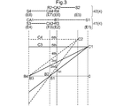
- FIG. 3 is a velocity diagram (collinear diagram) of the first transmission mechanism 41 and the second transmission mechanism 42 configured as described above.
- the vertical axis corresponds to the rotational speed of each rotating element (four rotating elements of the first transmission mechanism 41 and four rotating elements of the second transmission mechanism 42) shown in the upper part of FIG. Indicates that the rotational speed is zero, with the upper side being positive and the lower side being negative.
- the forward shift speeds are formed by controlling the engagement states of the respective engagement devices (C1, C2, C3, C4, B1, B2, B3, B4). .
- the parking range is to engage all four brakes (B1, B2, B3, B4) or two brakes (B1, B2, B3, B4) ( This is realized by engaging B1 and B3 or B2 and B4).
- a neutral range is implement
- the speed diagrams of the first speed change mechanism 41 and the second speed change mechanism 42 are overlapped so that the rotational speeds of the input gear mechanism 10 (common drive gear 13) are equal to each other.
- the third planetary gear mechanism 63 and the fourth planetary gear mechanism 64 single-pinion type planetary gear mechanisms having the same gear ratio (the gear ratio between the sun gear and the ring gear) are used. Therefore, as shown in FIG. 3, in the velocity diagram, the axis corresponding to the second rotation element E2 and the axis corresponding to the sixth rotation element E6 are arranged at the same position, and also correspond to the third rotation element E3.
- the shaft corresponding to the fourth rotating element E4 and the shaft corresponding to the eighth rotating element E8 are disposed at the same position.
- the side corresponding to the axis corresponding to the second rotating element E2 (the axis corresponding to the sixth rotating element E6) is opposite to the axis corresponding to the fifth rotating element E5 (see FIG.
- the gear ratio of the first planetary gear mechanism 61 and the gear ratio of the second planetary gear mechanism 62 are set so that the shaft corresponding to the first rotation element E1 is disposed on the right side in FIG.
- the ratio of the rotation speed of the first rotation element E1 to the rotation speed of the second rotation element E2 with respect to the rotation speed of the third rotation element E3 is the rotation speed of the seventh rotation element E7. Is larger in absolute value than the ratio of the rotation speed of the fifth rotation element E5 to the rotation speed of the sixth rotation element E6.
- the axis corresponding to the first rotation element E1 and the second rotation element E2 correspond to the interval between the axis corresponding to the second rotation element E2 and the axis corresponding to the third rotation element E3.
- first ratio The ratio of the distance to the shaft (hereinafter referred to as “first ratio”) corresponds to the fifth rotation element E5 with respect to the distance between the axis corresponding to the sixth rotation element E6 and the axis corresponding to the seventh rotation element E7. This is larger than the ratio of the distance between the rotating shaft and the shaft corresponding to the sixth rotating element E6 (hereinafter referred to as “second ratio”).
- the gear ratio step can be configured to become smaller toward the high speed side. It has become.
- the gear ratio step is the ratio of the gear ratio of the low speed gear to the gear ratio of the high speed gear among the adjacent gears.
- connection relationship of the planetary gear mechanism of the first transmission mechanism 41 and the connection relationship of the planetary gear mechanism of the second transmission mechanism 42 are different from each other. This makes it possible to set the value of the gear ratio step to an appropriate value for each of the combinations of adjacent gears.
- connection relationship when “the connection relationship of the planetary gear mechanisms is different” includes the connection relationship between the rotation elements of the different planetary gear mechanisms, the rotation elements of the planetary gear mechanism, the input shaft 90 and the output member 91.
- connection relationship of the pinion gear to the carrier in the planetary gear mechanism and the connection relationship between the rotation element of the speed change mechanism constituted by one or a plurality of planetary gear mechanisms and the input shaft 90 and the output member 91. That is, the connection relationship of the planetary gear mechanism of the first transmission mechanism 41 and the connection relationship of the planetary gear mechanism of the second transmission mechanism 42 are different from each other. At least one of these three connection relationships is the first transmission mechanism 41. And the second transmission mechanism 42 are different from each other. Note that the connection relationship of the pinion gear with respect to the carrier in the planetary gear mechanism is different between the first transmission mechanism 41 and the second transmission mechanism 42. This means that the connection relationship of the pinion gear with respect to the carrier is different from at least one of the planetary gear mechanisms included in the two speed change mechanism 42.
- the connection relationship between the two planetary gear mechanisms (61, 63) constituting the first transmission mechanism 41 is such that the ring gear of one planetary gear mechanism and the ring gear of the other planetary gear mechanism.
- the carrier relationship of one planetary gear mechanism and the sun gear of the other planetary gear mechanism are connected.
- the two planetary gear mechanisms (62, 64) constituting the second speed change mechanism 42 are connected in such a manner that the carrier of one planetary gear mechanism and the ring gear of the other planetary gear mechanism are connected, and one planetary gear mechanism is connected.
- the ring gear of the gear mechanism is connected to the carrier of the other planetary gear mechanism. That is, in the present embodiment, the connection relationship between the rotating elements of different planetary gear mechanisms is different between the first transmission mechanism 41 and the second transmission mechanism 42.
- four planetary gear mechanisms including two planetary gear mechanisms (61, 63) constituting the first transmission mechanism 41 and two planetary gear mechanisms (62, 64) constituting the second transmission mechanism 42 are provided.
- the connection relationship of the pinion gear to the carrier in one planetary gear mechanism (first planetary gear mechanism 61) is a double pinion type connection relationship, and the carriers in the remaining three planetary gear mechanisms (62, 63, 64). This is different from the pinion gear connection relationship (single pinion type connection relationship).
- the first speed change mechanism 41 includes a double pinion type planetary gear mechanism
- the second speed change mechanism 42 does not include a double pinion type planetary gear mechanism, whereby the pinion gear with respect to the carrier in the planetary gear mechanism.
- the connection relationship differs between the first transmission mechanism 41 and the second transmission mechanism 42.
- the rotating element (here, the first rotating element E1) that is the slowest or fastest in the order of the rotational speed is the input shaft.
- the rotating element (here, the second rotating element E2) adjacent to the rotating element in the order of the rotation speed is drivingly connected to the output member 91.
- the rotating element (here, the fifth rotating element E5) that is the slowest or the fastest in the order of the rotational speed is drivingly connected to the input shaft 90.
- the rotation elements adjacent to the rotation elements in the order of the rotation speed (here, the sixth rotation element E6) are drivingly connected to the output member 91. That is, in this embodiment, the connection relationship between the rotating element of the planetary gear mechanism and the input shaft 90 and the output member 91 is the same between the first transmission mechanism 41 and the second transmission mechanism 42.
- the second driven gear 22 is formed with a smaller diameter than the first driven gear 21. Therefore, the transmission gear ratio between the input gear mechanism 10 (common drive gear 13) and the first transmission mechanism 41 is defined as the first input gear ratio, and the input gear mechanism 10 (common drive gear 13), the second transmission mechanism 42, and the like.
- the first input side speed ratio and the second input side speed ratio are different from each other.
- the first input gear ratio is defined as the ratio of the rotational speed of the input gear mechanism 10 (common drive gear 13) to the rotational speed of the first driven gear 21, and the second input gear ratio is set to the second driven gear ratio.
- the second input side gear ratio is smaller than the first input side gear ratio.
- the rotational speed of the second sun gear S2 (the rotational speed of the second driven gear 22) in the state where the second clutch C2 is directly engaged is directly related to the first clutch C1.
- the rotational speed of the first sun gear S1 in the combined state (the rotational speed of the first driven gear 21) is higher.
- the ratio of the rotational speed of the shaft 90 (second input side gear ratio) is different.
- the first input side gear ratio is larger than the second input side gear ratio.
- the rotational speed of the input shaft 90 here is the rotational speed of the input shaft 90 when the seventh clutch C7 is directly connected.
- the first output gear 31 and the second output gear 32 are formed to have the same diameter. Therefore, if the transmission ratio between the first transmission mechanism 41 and the output member 91 is the first output-side transmission ratio, and the transmission ratio between the second transmission mechanism 42 and the output member 91 is the second output-side transmission ratio.
- the first output side gear ratio and the second output side gear ratio have the same value.
- the ratio of the rotational speed of the rotary element (second rotary element E2) that is drivingly connected to the output member 91 in the first transmission mechanism 41 to the rotational speed of the output member 91 first output side speed change).
- Ratio and the ratio of the rotation speed of the rotation element (sixth rotation element E6) drivingly connected to the output member 91 in the second transmission mechanism 42 to the rotation speed of the output member 91 (second output-side transmission ratio) are the same. It is. Unlike such a configuration, when the first output-side gear ratio is different from the second output-side gear ratio, that is, when the first output gear 31 and the second output gear 32 are gears having different diameters. The first output gear 31 and the second output gear 32 need to transmit a relatively large torque as compared with the first driven gear 21 and the second driven gear 22 by being decelerated by the automatic transmission 4.
- first output gear 31 and the second output gear 32 are gears having the same diameter, the same type of gear is used as the first output gear 31 and the second output gear 32. It is possible to reduce the manufacturing cost. Since the first driven gear 21 and the second driven gear 22 have different diameters, it is necessary to use two types of gears as the first driven gear 21 and the second driven gear 22.
- first driven gear 21 and the second driven gear 22 have a smaller torque that needs to be transmitted than the first output gear 31 and the second output gear 32, the required strength is ensured. Is easier. Therefore, compared with the case where two types of gears are used as the first output gear 31 and the second output gear 32, the manufacturing cost can be reduced. Further, since the first output side gear ratio and the second output side gear ratio have the same value as described above, the first output gear 31 and the first output gear 31 and the second output gear ratio can be changed without changing the gear ratio step in each of the adjacent gear stage combinations. It is possible to change the gear ratio between the input gear mechanism 10 and the output member 91 by changing the gear ratio between the second output gear 32 and the differential input gear 7a.
- the gear ratio between the input gear mechanism 10 and the output member 91 in accordance with the vehicle type on which the vehicle drive transmission device 1 is mounted.
- the first driven gear 21 and the second driven gear 21 and the second gear are not changed without changing the gear ratio step in each of the combinations of adjacent gears.
- the gear ratio between the driven gear 22 and the input gear mechanism 10 can be changed, and the gear ratio between the input gear mechanism 10 and the output member 91 can be changed.
- both the minimum speed ratio realized by the first speed change mechanism 41 and the minimum speed ratio realized by the second speed change mechanism 42 are 1.
- the speed ratio realized by the first speed change mechanism 41 is the rotational speed (first speed) of the first sun gear S1 with respect to the rotational speeds of the first ring gear R1 and the third ring gear R3 (rotational speed of the second rotational element E2).
- 1 is a ratio of the rotation speed of one rotation element E1.
- the speed ratio realized by the second speed change mechanism 42 here is the rotational speed (second speed) of the second sun gear S2 with respect to the rotational speed of the second carrier CA2 and the fourth ring gear R4 (rotational speed of the sixth rotational element E6). Ratio of the rotation speed of the five-rotation element E5).
- the transmission ratio realized by the first transmission mechanism 41 is 1, which is the minimum. All the rotating elements (four rotating elements in this embodiment) of the speed change mechanism 41 are in a state of rotating integrally at the same speed. That is, the differential transmission of the planetary gear mechanism constituting the first transmission mechanism 41 is prohibited, so that the power transmission efficiency in the first transmission mechanism 41 becomes the highest. Further, in the present embodiment, when the automatic transmission 4 (second transmission mechanism 42) forms the sixth stage 6th, the transmission ratio realized by the second transmission mechanism 42 is the minimum 1, and in this state, All the rotary elements (four rotary elements in the present embodiment) of the second transmission mechanism 42 are in a state of integrally rotating at the same speed.
- the differential transmission of the planetary gear mechanism that constitutes the second transmission mechanism 42 is prohibited, so that the power transmission efficiency in the second transmission mechanism 42 becomes the highest.
- the minimum speed ratio realized by the first speed change mechanism 41 and the second speed change mechanism 42 is generally realized during traveling as compared to other speed ratios realized by the first speed change mechanism 41 and the second speed change mechanism 42. Is long and has a great influence on the energy efficiency of the vehicle drive transmission device 1. Therefore, as described above, for both the first transmission mechanism 41 and the second transmission mechanism 42, the minimum transmission ratio is set to 1, which maximizes the power transmission efficiency in the transmission mechanism (41, 42).
- the transmission efficiency of the power between the input gear mechanism 10 (common drive gear 13) and the output member 91 in a state where the transmission gear ratio is realized is ensured, and the energy efficiency of the vehicle drive transmission device 1 is improved. It is possible to improve.
- the first input side speed ratio and the second input side speed ratio are different from each other, and the first output side speed ratio and the second output side speed ratio are the same value. Become. Therefore, in the present embodiment, the product of the first input side speed ratio and the first output side speed ratio and the product of the second input side speed ratio and the second output side speed ratio are different from each other. As a result, even when both the minimum speed ratio realized by the first speed change mechanism 41 and the minimum speed ratio realized by the second speed change mechanism 42 are 1, the first speed change mechanism 41 has the minimum speed change. When the ratio is realized (in this embodiment, the fifth stage 5th is formed), and when the second speed change mechanism 42 realizes the minimum speed ratio (in this embodiment, the sixth speed is 5th).
- the gear ratio between the input gear mechanism 10 (common drive gear 13) and the output member 91 can be made different in the case where the stage 6th is formed.
- the first input gear ratio is derived.
- the second input side gear ratio, the first output side gear ratio, and the second output side gear ratio are all on the input gear mechanism 10 side with respect to the rotational speed of the member disposed on the output member 91 side in the power transmission path. It is set as the ratio of the rotational speed of the member arrange
- the product of the first input-side gear ratio and the first output-side gear ratio is the first gear ratio that is the gear ratio from the input shaft 90 to the output member 91 when the first clutch C1 and the third clutch C3 are directly connected. equal.
- the first gear ratio is determined when the second clutch C2 is in the released state in addition to the first clutch C1 and the third clutch C3 (in the present embodiment, the seventh clutch C7 is further in the directly connected state).
- the gear ratio from the input shaft 90 to the output member 91 in a case where it exists.
- the product of the second input side gear ratio and the second output side gear ratio is the second gear ratio that is the gear ratio from the input shaft 90 to the output member 91 in the directly connected state of the second clutch C2 and the fourth clutch C4. Equal to the ratio.
- the second gear ratio is determined when the first clutch C1 is in the released state in addition to the second clutch C2 and the fourth clutch C4 being in the directly connected state (in this embodiment, the seventh clutch C7 is further in the directly connected state).
- the gear ratio from the input shaft 90 to the output member 91 in a case where it exists.
- the product of the first input gear ratio and the first output gear ratio is different from the product of the second input gear ratio and the second output gear ratio.
- the first gear ratio and the second gear ratio are different from each other.
- by setting the first transmission ratio to a value larger than the second transmission ratio that is, a large reduction ratio
- an odd number of stages is formed by the first transmission mechanism 41, and the second transmission mechanism 42.
- an even number of stages is formed.
- both the first clutch C1 and the second clutch C2 are friction engagement devices.
- the seventh clutch C7 is also a friction engagement device.
- the friction engagement device is an engagement device that transmits torque by a frictional force generated between engagement members engaged with each other.
- a hydraulically driven frictional engagement device or an electromagnetically driven frictional engagement device can be used as the first clutch C1, the second clutch C2, and the seventh clutch C7.
- the first clutch C1 is engaged and the second clutch C2 is released.
- the rotation of the input gear mechanism 10 (common drive gear 13) is shifted by the first transmission mechanism 41 forming an odd number of stages and transmitted to the output member 91, whereby the internal combustion engine 2 and the rotation are rotated.
- the wheel 9 is driven by at least one output torque of the electric machine 3, and the second speed change mechanism 42 predicts a shift change of two even speed stages adjacent to the odd speed speed formed by the first speed change mechanism 41.
- the even numbered stage is formed, and a shift-up or shift-down standby state is established.
- the second clutch C2 can be engaged with the first clutch C1 controlled to the slip engagement state. That is, the second clutch C2 is engaged in a state where the output torque of at least one of the internal combustion engine 2 and the rotating electrical machine 3 is transmitted to the output member 91 and the wheel 9 via the first clutch C1 in the sliding engagement state.
- the second clutch C2 is engaged in a state where the output torque of at least one of the internal combustion engine 2 and the rotating electrical machine 3 is transmitted to the output member 91 and the wheel 9 via the first clutch C1 in the sliding engagement state.
- all of the engagement devices included in the first transmission mechanism 41 and the second transmission mechanism 42 are meshing engagement devices (dog clutches). That is, in the example shown in FIG. 1, both the shift stage switching in the first transmission mechanism 41 and the shift stage switching in the second transmission mechanism 42 are switching of the engagement state by the meshing engagement device. Is done. For example, by using a meshing engagement device driven by an electric actuator for these engagement devices, it is possible to greatly reduce the number of components that are hydraulically operated.
- the meshing engagement device is provided with a synchronization mechanism (synchronization mechanism) that synchronizes the rotation of the two rotation members to be engaged.
- the third clutch C3, the first brake B1, and the third brake B3 are all planetary gear mechanisms (the first planetary gear mechanism 61 and the first planetary gear mechanism 61) provided in the first transmission mechanism 41.
- the first planetary gear mechanism 63) is disposed on the first axial side.
- the fourth clutch C4, the second brake B2, and the fourth brake B4 are all planetary gear mechanisms (the second planetary gear mechanism 62 and the fourth planetary gear mechanism 64) included in the second transmission mechanism 42. ) On the first axial side.
- the meshing engagement device includes a sleeve 80 that moves in the axial direction L, and the engagement state of the meshing engagement device is changed by switching the position of the sleeve 80 in the axial direction L. Can be switched.
- the third clutch C ⁇ b> 3 and the first brake B ⁇ b> 1 are configured as a meshing engagement device having a common sleeve 80, and the first clutch B ⁇ b> 1 and the first brake B ⁇ b> 1 are arranged according to the position of the sleeve 80 in the axial direction L.
- the fourth clutch C4 and the fourth brake B4 are configured as a meshing type engaging device having a common sleeve 80, and depending on the position of the sleeve 80 in the axial direction L.
- the first rotation element E1 of the four rotation elements (E1 to E4) included in the first transmission mechanism 41 is drivingly connected to the input shaft 90 without passing through other rotation elements.
- the first specific rotation element F1 which is any one of the rotation elements of the first speed change mechanism 41 (the rotation element other than the first rotation element E1), also passes through the other rotation elements. Without being connected to the input shaft 90.
- the first specific rotation element F1 is the fourth rotation element E4, and the fourth rotation element E4 is input via the fifth clutch C5. Drive coupled to the shaft 90.
- the first transmission mechanism 41 can form a reverse gear stage (Rev) by releasing both C1 and the second clutch C2 and engaging both the fifth clutch C5 and the first brake B1. It has become.
- Rev reverse gear stage
- the ratio of the rotation speed of the input shaft 90 to the rotation speed of the first specific rotation element F1 in the direct connection state of the fifth clutch C5 (and the release state of the first clutch C1) is the first clutch C1.
- the first gear mechanism G1 that drives and connects the input shaft 90 and the first transmission mechanism 41 without the first clutch C1, the first specific rotation element F1, and the first
- the vehicle drive transmission device 1 with the fifth clutch C5 that selectively connects the gear mechanism G1 to the drive
- the configuration in which the first specific rotating element F1 is connected to the input shaft 90 as described above is realized. is doing.
- the first gear mechanism G1 is configured by using the third driven gear 23 and the second gear 72 that meshes with both the first gear 71 and the third driven gear 23.
- the first gear 71 has a rotor shaft on the first axial side L1 with respect to the rotor of the rotating electrical machine 3 (that is, on the opposite side of the axial direction L from the side where the output rotating member 3a is disposed). It is provided so as to rotate integrally with the output rotating member 3a via 3b.
- the third driven gear 23 is provided so as to rotate integrally with the first specific rotation element F1 when the fifth clutch C5 is directly connected.
- the second gear 72 is on a different axis from the first axis A1 where the third driven gear 23 is arranged and the fifth axis A5 where the first gear 71 is arranged (for example, on the third axis A3). Placed in.
- the second gear 72 is an idler gear. Therefore, the rotation of the input shaft 90 (or the rotation of the input gear mechanism 10) is performed via the output rotation member 3a, the first gear 71, the second gear 72, the third driven gear 23, and the fifth clutch C5. It is transmitted to the first specific rotation element F1.
- each gear constituting the first gear mechanism G1 and the axial center position of the second gear 72 are input shafts with respect to the rotational speed of the first specific rotating element F1 in the directly connected state of the fifth clutch C5.
- the ratio of 90 rotational speeds is designed to be a desired value.
- the second specific rotation element F2 that is any one of the rotation elements (the rotation element other than the fifth rotation element E5) is also another rotation element. It is drivingly connected to the input shaft 90 without going through.
- the second specific rotation element F2 is the seventh rotation element E7, and the seventh rotation element E7 is input via the sixth clutch C6. Drive coupled to the shaft 90.
- the speed ratio from the input shaft 90 to the output member 91 in the directly connected state of the fourth clutch C4 and the sixth clutch C6 is smaller than the second speed ratio (that is, a smaller reduction ratio). It is comprised so that it may become.
- the ratio of the rotation speed of the input shaft 90 to the rotation speed of the second specific rotation element F2 in the direct connection state of the sixth clutch C6 (and the release state of the second clutch C2) is determined as the direct connection of the second clutch C2. It is smaller than the ratio of the rotational speed of the input shaft 90 to the rotational speed of the fifth rotating element E5 in the state (and the disengaged state of the sixth clutch C6).
- the rotation element to which the rotation of the input shaft 90 is input can be switched from the fifth rotation element E5 to a rotation element other than the fifth rotation element E5 (in this embodiment, the seventh rotation element E7).
- the gear ratio from the input shaft 90 to the output member 91 in the directly connected state of the fourth clutch C4 and the sixth clutch C6 is set to be a reduction gear ratio smaller than the second gear ratio.
- the forward gear ratio is smaller than the sixth speed 6th.
- the gear stage (seventh stage 7th) can be formed by the second transmission mechanism 42.
- the seventh speed 7th is the fifth speed 5th or Similar to the sixth stage 6th, this is a direct coupling stage that is realized in a state where all the rotating elements of the speed change mechanism (41, 42) rotate integrally at the same speed.
- the second gear mechanism G2 that drives and connects the input shaft 90 and the second transmission mechanism 42 without the second clutch C2, the second specific rotation element F2, and the second
- the sixth clutch C6 that selectively drives and connects the gear mechanism G2 is provided in the vehicle drive transmission device 1, thereby realizing the configuration in which the second specific rotating element F2 is driven and connected to the input shaft 90 as described above. is doing.
- the output rotating member 3a, the first gear 71, the fourth driven gear 24 that is drivingly connected to the second specific rotating element F2 via the sixth clutch C6, the first gear 71 and the fourth gear.
- the second gear mechanism G ⁇ b> 2 is configured using the second gear 72 that meshes with both of the driven gears 24.
- the third driven gear 23 and the fourth driven gear 24 mesh with the second gear 72 at different positions in the circumferential direction (a circumferential direction with respect to an axis on which the second gear 72 is disposed). Further, the fourth driven gear 24 is provided so as to rotate integrally with the second specific rotation element F2 in a directly connected state of the sixth clutch C6. Therefore, the rotation of the input shaft 90 (or the rotation of the input gear mechanism 10) is performed via the output rotation member 3a, the first gear 71, the second gear 72, the fourth driven gear 24, and the sixth clutch C6. It is transmitted to the second specific rotation element F2.
- the second specific rotation element F2 may be the sixth rotation element E6 or the eighth rotation element E8 instead of the seventh rotation element E7.
- each gear constituting the second gear mechanism G2 and the axial center position of the second gear 72 are input shafts with respect to the rotational speed of the second specific rotating element F2 in the directly connected state of the sixth clutch C6.
- the ratio of 90 rotational speeds is designed to be a desired value.
- some gears constituting the first gear mechanism G1 are disposed coaxially with the rotating electrical machine 3. .
- some gears constituting the second gear mechanism G2 are arranged coaxially with the rotating electrical machine 3. That is, a part of the gears (here, the output rotating member 3a and the first gear 71) that are arranged coaxially with the rotating electrical machine 3 and constitute the first gear mechanism G1 constitute a part of the second gear mechanism G2. It is common with other gears.
- the output rotating member 3a and the first gear 71 arranged coaxially with the rotating electrical machine 3 are used in common for the first gear mechanism G1 and the second gear mechanism G2, and in this embodiment, the rotating electrical machine 3 is further used.
- the second gear 72 arranged on a separate axis is also commonly used for the first gear mechanism G1 and the second gear mechanism G2.
- the automatic transmission 4 (here, the first transmission mechanism 41) forms a reverse gear. It is configured to be possible.
- the rotary electric machine 3 is used mainly for generating assist torque and generating power (regeneration) (that is, the rotary electric machine 3 having a lower output than a plug-in hybrid vehicle or the like). Can be suitably used. That is, in the vehicle drive transmission device 1 of the present embodiment, the rotary electric machine 3 having a relatively low output (that is, relatively small) is easily used, and the rotary electric machine 3 in the vehicle drive transmission device 1 is arranged.
- the first gear mechanism G1 and the second gear mechanism G2 are arranged on the same axis as the rotating electrical machine 3 while suppressing an increase in the size of the portion in the axial direction L (in this embodiment, the first gear 71 in the present embodiment). ) Can be secured.
- the fifth clutch C5 is provided in the arrangement space of the third brake B3 in the vehicle drive transmission device 1 of the first embodiment, and the sixth clutch C6 is disposed in the above-described manner. It is provided in the arrangement space of the second brake B2 in the vehicle drive transmission device 1 of the first embodiment.
- both the fifth clutch C5 and the sixth clutch C6 are meshing engagement devices.
- the band brake which has the brake band 81 is used as 2nd brake B2 and 3rd brake B3.
- the brake band 81 is wound around the outer peripheral portion of a cylindrical member that rotates integrally with the rotating element to be braked, and the rotating element is fixed to the case 6 by tightening the brake band 81.
- the axial direction L of the automatic transmission 4 can be achieved as compared with the case where the second brake B2 and the third brake B3 are engaged engagement devices.
- the fifth clutch C5 and the sixth clutch C6 can be provided while suppressing an increase in size.
- the vehicle drive transmission device 1 has a configuration in which it is easy to use the rotating electrical machine 3 having a relatively low output (that is, the rotating electrical machine 3 having a relatively small regeneration torque during regeneration) as described above. ing. Therefore, even when a band brake having rotational directionality is used as the second brake B2 or the third brake B3, the second brake B2 or the third brake B3 is required for regeneration. The torque capacity is easily secured.
- connection relationship between the rotating elements of different planetary gear mechanisms in the first transmission mechanism 41 and the second transmission mechanism 42 shown in the first and second embodiments is an example.
- the connection relationship of the rotating elements between different planetary gear mechanisms in the two-speed change mechanism 42 can be changed as appropriate.
- the connection relationship between the two planetary gear mechanisms (61, 63) constituting the first transmission mechanism 41 is the same as that of the ring gear of one planetary gear mechanism and the other planetary gear mechanism.
- the connection relationship between the two planetary gear mechanisms (62, 64) constituting the second transmission mechanism 42 is set so that the carrier of one planetary gear mechanism and the planetary gear mechanism of the other planetary gear mechanism are connected.
- the ring gear is connected, and the ring gear of one planetary gear mechanism and the carrier of the other planetary gear mechanism are connected.
- the two planetary gear mechanisms (62, 62) constituting the second transmission mechanism 42 are used. 64), the sun gear of one planetary gear mechanism and the sun gear of the other planetary gear mechanism are connected, and the ring gear of one planetary gear mechanism and the carrier of the other planetary gear mechanism are connected. It can also be a relationship.
- the first transmission mechanism 41 and the second transmission mechanism have the following relationship: the rotational relationship between the different planetary gear mechanisms and the connection relationship of the pinion gear to the carrier in the planetary gear mechanism.
- the configuration different from that of 42 has been described.
- only one of the connection relationship between the rotating elements of different planetary gear mechanisms and the connection relationship of the pinion gear with respect to the carrier in the planetary gear mechanism is the first transmission mechanism 41 and the second transmission mechanism 41.
- Different configurations from the transmission mechanism 42 may be employed.
- both the first transmission mechanism 41 and the second transmission mechanism 42 are configured to include two single pinion type planetary gear mechanisms (that is, the connection relationship of the pinion gear with respect to the carrier in the planetary gear mechanism is the same as that of the first transmission mechanism 41.
- the second transmission mechanism 42 is configured to be the same), and the rotational relationship between the different planetary gear mechanisms is different between the first transmission mechanism 41 and the second transmission mechanism 42.
- two planetary gear mechanisms constituting one of the first transmission mechanism 41 and the second transmission mechanism 42 are connected to each other by connecting the carrier of one planetary gear mechanism and the ring gear of the other planetary gear mechanism.
- the ring gear of one planetary gear mechanism is connected to the carrier of the other planetary gear mechanism, and the two planetary gear mechanisms constituting the other of the first transmission mechanism 41 and the second transmission mechanism 42 are connected.
- the relationship is such that the sun gear of one planetary gear mechanism and the sun gear of the other planetary gear mechanism are connected, and the carrier of one planetary gear mechanism and the ring gear of the other planetary gear mechanism are connected. Can do.
- connection relationship between the rotating element of the planetary gear mechanism and the input shaft 90 and the output member 91 is the same between the first transmission mechanism 41 and the second transmission mechanism 42.
- the configuration is described as an example.
- the connection relationship between the rotating element of the planetary gear mechanism and the input shaft 90 and the output member 91 is not limited to such a configuration, and the first transmission mechanism 41 and the second transmission mechanism 42 are different from each other. It can also be configured.
- at least one of the connection relationship of the rotating elements between the different planetary gear mechanisms and the connection relationship of the pinion gear to the carrier in the planetary gear mechanism is the same between the first transmission mechanism 41 and the second transmission mechanism 42. It can also be configured.
- the ratio of the rotational speed of the input shaft 90 to the rotational speed of the first rotating element E1 when the first clutch C1 is directly connected (first input side gear ratio); Unlike the ratio of the rotation speed of the input shaft 90 to the rotation speed of the fifth rotation element E5 in the directly connected state of the second clutch C2 (second input side gear ratio), the second rotation element E2 with respect to the rotation speed of the output member 91 is different.
- An example of a configuration in which the ratio of the rotation speeds of the first rotation speed (the first output-side speed ratio) and the ratio of the rotation speed of the sixth rotating element E6 to the rotation speed of the output member 91 (second output-side speed ratio) is the same will be described. did.
- the present invention is not limited to such a configuration, and the first input side speed ratio and the second input side speed ratio are the same, and the first output side speed ratio and the second output side speed ratio are different.
- the first input side speed ratio and the second input side speed ratio may be different, and the first output side speed ratio and the second output side speed ratio may be different.
- the configuration in which the first speed ratio is a reduction ratio larger than the second speed ratio has been described as an example.
- the present invention is not limited to such a configuration, and a configuration in which the first gear ratio is a reduction gear ratio smaller than the second gear ratio can also be adopted.
- the first speed change mechanism 41 forms an even number of steps
- the second speed change mechanism 42 forms an odd number of steps.
- the gear that meshes with both the first gear 71 and the third driven gear 23 and the gear that meshes with both the first gear 71 and the fourth driven gear 24 are common.
- the configuration that is the gear (second gear 72) has been described as an example.
- the present invention is not limited to such a configuration, and there is a gear that meshes with both the first gear 71 and the fourth driven gear 24 separately from the gear that meshes with both the first gear 71 and the third driven gear 23. It can also be set as the structure provided. In this case, it is also possible to arrange these two gears on different axes.
- the gear (fourth gear) that meshes with both the first gear 71 and the fourth driven gear 24 may include two gear portions (a gear portion meshing with the third gear and a gear portion meshing with the fourth gear) arranged side by side in the axial direction L. Further, a configuration in which the first gear 71 and the third driven gear 23 are directly meshed with each other, or a configuration in which the first gear 71 and the fourth driven gear 24 are directly meshed with each other is possible.
- a part of the gears constituting the first gear mechanism G1 is arranged coaxially with the rotating electrical machine 3, and the part of the gears constituting the second gear mechanism G2 is rotated.
- the configuration arranged coaxially with the electric machine 3 has been described as an example.
- the present invention is not limited to such a configuration, and all the gears constituting the first gear mechanism G1 are arranged on a different axis from the rotating electrical machine 3, or all the gears constituting the second gear mechanism G2. May be arranged on a different axis from the rotating electrical machine 3.
- the configuration in which the first gear mechanism G1 is used to form the reverse gear is described as an example.
- the present invention is not limited to such a configuration, and the first gear mechanism G1 is used not only to form the reverse gear stage but also to form a direct gear stage having a gear ratio different from the fifth gear stage 5th.
- the first gear mechanism G1 may be configured to be used only for forming a direct coupling stage having a gear ratio different from that of the fifth stage 5th.
- a direct gear stage having a gear ratio different from the fifth gear stage 5th can be formed by engaging both the third clutch C3 and the fifth clutch C5.
- the gear ratio from the input shaft 90 to the output member 91 in the directly connected state of the third clutch C3 and the fifth clutch C5 is set to be a reduction ratio smaller than the first gear ratio.
- a direct gear having a gear ratio different from 5th can be a gear having a smaller gear ratio than the fifth gear 5th.
- the first specific rotation element F1 is replaced with the fourth rotation element E4. It can also be the 2 rotation element E2 or the 3rd rotation element E3.
- the configuration in which the second gear mechanism G2 is used only for forming a direct coupling stage having a speed ratio different from that of the sixth stage 6th has been described as an example.
- the present invention is not limited to such a configuration, and the second gear mechanism G2 is also used to form a reverse gear stage in addition to the direct connection stage having a gear ratio different from that of the sixth stage 6th.
- the second gear mechanism G2 may be configured to be used only for forming the reverse gear.
- the second specific rotation element F2 is the eighth rotation element E8. Note that, when the second gear mechanism G2 is used only for forming a reverse gear, unlike the second embodiment, the second specific rotation element F2 in the directly connected state of the sixth clutch C6 is used.
- the ratio of the rotational speed of the input shaft 90 to the rotational speed of the input shaft 90 is set to the same value as the ratio of the rotational speed of the input shaft 90 to the rotational speed of the fifth rotating element E5 in the directly connected state of the second clutch C2. Can also be set to a large value.
- the configuration in which the output rotation member 3a of the rotating electrical machine 3 meshes with the common drive gear 13 has been described as an example.
- the configuration is not limited to such a configuration, and the output rotation member 3a of the rotating electrical machine 3 and the common drive gear 13 may be driven and connected via another transmission member (such as an idler gear).
- the output rotating member 3a of the rotating electrical machine 3 is configured to mesh with the first driven gear 21 or the second driven gear 22, so that the output rotating member 3a of the rotating electrical machine 3 and the common driving gear 13 are the first.
- a configuration may be adopted in which driving and coupling are performed via the driven gear 21 or the second driven gear 22.
- the output rotating member 3a of the rotating electrical machine 3 is disposed closer to the input shaft 90 than the speed change mechanism (the first speed change mechanism 41 and the second speed change mechanism 42) in the power transmission path connecting the input shaft 90 and the output member 91. It is configured to be connected to a member (for example, the output member 91) disposed on the output member 91 side rather than the transmission mechanism (the input gear mechanism 10 in the above embodiment) rather than the speed change mechanism in the power transmission path. You can also.
- the configuration in which the rotating electrical machine 3 is arranged on a different shaft from the first transmission mechanism 41 and the second transmission mechanism 42 has been described as an example.
- the present invention is not limited to such a configuration, and the rotary electric machine 3 may be arranged coaxially with one of the first transmission mechanism 41 and the second transmission mechanism 42.
- the configuration in which the rotating electrical machine 3 is disposed on a different shaft from the input shaft 90 has been described as an example.
- the rotating electrical machine 3 is disposed coaxially with the input shaft 90. It can also be set as a structure.
- the output rotating member 3a is not an output gear as in the above embodiments, but is connected so as to rotate integrally with a shaft member (rotor shaft 3b or rotor shaft 3b) that rotates integrally with the rotor of the rotating electrical machine 3. Shaft member).
- the configuration in which the differential input gear 7a is used as the output member 91 has been described as an example.
- a gear mechanism eg, A counter gear mechanism
- a gear included in the gear mechanism may be used as the output member 91 (functions as the output member 91).
- the configuration in which the input gear mechanism 10 includes the common drive gear 13 that meshes with both the first driven gear 21 and the second driven gear 22 has been described as an example.
- the input gear mechanism 10 includes a first drive gear that meshes with the first driven gear 21 and a second drive gear that meshes with the second driven gear 22. It can also be configured.
- the first speed change mechanism 41 changes the speed of the rotation of the first drive gear included in the input gear mechanism 10 and transmits it to the output member 91
- the second speed change mechanism 42 corresponds to the second drive gear provided in the input gear mechanism 10. Is rotated and transmitted to the output member 91.
- the first clutch C1 is replaced with a power transmission path between the input gear mechanism 10 and the first transmission mechanism 41.
- the input shaft 90 is provided in a power transmission path between the input gear 90 and the first drive gear
- the second clutch C2 is replaced with a power transmission path between the input gear mechanism 10 and the second transmission mechanism 42, and the input shaft 90 And a second power transmission path between the first drive gear and the second drive gear.
- the first clutch C1 connects or disconnects the input shaft 90 and the first drive gear
- the second clutch C2 connects or disconnects the input shaft 90 and the second drive gear.
- the output rotation member 3a of the rotating electrical machine 3 is either one of the first drive gear and the second drive gear. It can also be set as the structure which meshes.
- the configuration in which the vehicle drive transmission device 1 includes the seventh clutch C7 has been described as an example.
- the present invention is not limited to such a configuration, and the vehicle drive transmission device 1 does not include the seventh clutch C7, and the input shaft 90 and the input gear mechanism 10 (common drive gear 13) rotate integrally. You can also.
- the drive transmission device 1 for vehicles demonstrated as an example the structure provided with the rotary electric machine 3 (rotary electric machine as a driving force source of the wheel 9).
- the present invention is not limited to such a configuration, and the vehicle drive transmission device 1 may be configured not to include the rotating electrical machine 3.
- the first transmission mechanism (41) is connected to the input member (90) via a second clutch (C2).
- Each of the speed change mechanism (41) and the second speed change mechanism (42) includes a planetary gear mechanism.
- the connection relationships of the gear mechanisms are different from each other.
- the first transmission mechanism ( 41) input / output rotational speed ratios of the respective speed stages (rotational elements that are drivingly connected to the input member (90) in the first transmission mechanism (41) and output members (91 in the first transmission mechanism (41)).
- the input / output rotational speed ratio of each gear stage formed by the second transmission mechanism (42) input member in the second transmission mechanism (42)
- 90) and the rotation speed ratio between the rotation element driven and connected to the output member (91) in the second speed change mechanism (42) can be easily made different from each other. .
- the first transmission mechanism (41) is connected to the input member (90) via a second clutch (C2).
- Each of the speed change mechanism (41) and the second speed change mechanism (42) includes a planetary gear mechanism, and the first speed change mechanism (41) includes a plurality of shift speeds that can be formed by the automatic transmission (4). Odd-numbered stages, and the second speed change mechanism (42) Forming a several stages, it becomes smaller as the ratio of the speed ratio between the adjacent gear is, toward the high-speed stage side.
- the torque fluctuation that is, shift shock
- the value of the gear ratio step in each of the adjacent gear stage combinations can be set to an appropriate value from the viewpoint of the gear feeling.
- the first transmission mechanism (41) includes a double pinion type planetary gear mechanism
- the second transmission mechanism (42) does not include a double pinion type planetary gear mechanism.
- the first transmission mechanism (41) and the second transmission mechanism (42) do not include a double pinion planetary gear mechanism, or the first transmission mechanism (41) and the second transmission mechanism.
- the first speed change mechanism (41) includes a double pinion type planetary gear mechanism
- the second speed change mechanism (42) does not include a double pinion type planetary gear mechanism.
- the first transmission mechanism (41) includes a first sun gear (S1), a first carrier (CA1), a double pinion type first planetary gear mechanism (61) including a first ring gear (R1), a third sun gear ( S3), a third carrier (CA3), and a single pinion type third planetary gear mechanism (63) provided with a third ring gear (R3), the speed change mechanism comprising the first sun gear ( The first rotating element (E1) which is S1), the second rotating element (E2) which is the first ring gear (R1) and the third ring gear (R3) which rotate integrally, and the third carrier (CA3).
- the second speed change mechanism (42) includes a single pinion type second planetary gear mechanism (62) including a second sun gear (S2), a second carrier (CA2), and a second ring gear (R2), and a fourth sun gear.
- the fifth rotation is (S2) (E5), the second carrier (CA2) rotating integrally and the sixth rotating element (E6) which is the fourth ring gear (R4), the second ring gear (R2) rotating integrally and the fourth ring gear (R4).
- a seventh rotating element (E7) as a carrier (CA4) and an eighth rotating element (E8) as the fourth sun gear (S4) are provided, and the fifth rotating element (E5) and the sixth rotating element are provided.
- the non-rotating member (6) is selectively fixed by (B1).
- the fourth rotating element (E4) is selectively fixed to the non-rotating member (6) by a third brake (B3), and the fifth rotating element (E5) is fixed to the second clutch (C2).
- the sixth rotating element (E6) is drivingly connected to the output member (91), and the seventh rotating element (E7) is connected to the non-rotating member (6) by the second brake (B2).
- the eighth rotating element (E8) is selectively fixed to the non-rotating member (6) by a fourth brake (B4), and the first clutch (C1) and the third clutch (C3) are selectively fixed.
- the first gear ratio which is the speed ratio from the input member (90) to the output member (91), and the directly connected state of the second clutch (C2) and the fourth clutch (C4). From the input member (90) to the output member (91) It is preferable to the second gear ratio is the gear ratio is different from each other configurations.
- each of the first transmission mechanism (41) and the second transmission mechanism (42) is configured to be capable of forming three shift stages in which the shift stage having the smallest speed ratio is a direct connection stage, It is possible to ensure a high degree of freedom in designing the gear ratio step by making the planetary gear mechanism different in connection between the first transmission mechanism (41) and the second transmission mechanism (42). As a result, for example, it is possible to realize a configuration in which the gear ratio step decreases as it goes toward the high speed stage.
- the first speed ratio is a reduction ratio larger than the second speed ratio.
- the first transmission mechanism (41) configured by using the first planetary gear mechanism (61) of the double pinion type and the third planetary gear mechanism (63) of the single pinion type has a gear ratio.
- An odd number including the maximum gear can be formed, and the gear ratio step value can be easily set to an appropriate value for each combination of adjacent gears.
- the ratio of the rotational speed of the rotary element (E2) that is drivingly connected to the output member (91) in the first transmission mechanism (41) to the rotational speed of the output member (91), and the output member (91) It is preferable that the ratio of the rotational speed of the rotating element (E6) driven and connected to the output member (91) in the second transmission mechanism (42) to the rotational speed of the second speed change mechanism (42) is the same.
- the second transmission member (gear, etc.) for transmitting power between the output member (91) and the rotating element (E6) that is drivingly connected to the output member (91) in the second transmission mechanism (42). Can be a common part.
- the first transmission member and the second transmission member that need to transmit a relatively large torque by being decelerated by the automatic transmission (4) for example, different types of transmission members (for example, , Gears having different diameters) need to be used, and there is a risk of increasing the manufacturing cost of the vehicle drive transmission device (1), for example, the number of verification necessary items for securing strength increases as the types of transmission members increase. There is.
- the manufacturing cost of a vehicle drive transmission device (1) can be suppressed.
- the common speed ratio can be changed without changing the speed ratio step in each combination of adjacent speed stages. It is possible to change the speed ratio between the input member (90) and the output member (91) by changing the first output side speed ratio and the second output side speed ratio. As a result, it becomes easy to change the gear ratio between the input member (90) and the output member (91) in accordance with the vehicle type to be mounted on the vehicle drive transmission device (1).
- the first speed change mechanism (41) includes a first rotating element (E1), a second rotating element (E2), a third rotating element (E3), and a fourth rotating element (E4) in order of rotational speed. And two of the first rotating element (E1), the second rotating element (E2), the third rotating element (E3), and the fourth rotating element (E4) are selectively provided.
- a third clutch (C3) to be connected is provided, the first rotating element (E1) is drivingly connected to the first clutch (C1), and the second rotating element (E2) is connected to the output member (91).
- the third rotating element (E3) is selectively connected to the non-rotating member (6) by the first brake (B1), and the fourth rotating element (E4) is connected to the third brake (B3).
- a first clutch (C1) for drivingly connecting the input member (90) and the first transmission mechanism (41) without using an intermediate member, and the first transmission mechanism (41).
- a fifth clutch (C5) for selectively driving and connecting the first specific rotation element (F1) and the first gear mechanism (G1), wherein the first specific rotation element (F1) is the fourth rotation.
- the element (E4) is preferable.
- the first clutch (C1) is disengaged and both the fifth clutch (C5) and the first brake (B1) are engaged, so that the reverse gear position is changed to the first transmission mechanism (41). ). Therefore, for example, even when the vehicle drive transmission device (1) includes the rotating electrical machine (3) as the driving force of the wheels (9), the vehicle is moved backward without using the driving force of the rotating electrical machine (3). Therefore, a suitable vehicle drive transmission device (1) can be realized even when a rotating electrical machine (3) having a relatively low output is used.
- the second speed change mechanism (42) includes a fifth rotating element (E5), a sixth rotating element (E6), a seventh rotating element (E7), and an eighth rotating element (E8) in the order of rotational speed. And two of the fifth rotating element (E5), the sixth rotating element (E6), the seventh rotating element (E7), and the eighth rotating element (E8) are selectively provided.
- a fourth clutch (C4) to be connected is provided, the fifth rotating element (E5) is drivingly connected to the second clutch (C2), and the sixth rotating element (E6) is connected to the output member (91).
- the seventh rotating element (E7) is selectively fixed to the non-rotating member (6) by the second brake (B2), and the eighth rotating element (E8) is driven by the fourth brake (B4).
- the second clutch (C2 A second gear mechanism (G2) for drivingly connecting the input member (90) and the second speed change mechanism (42) without any intervention, and a rotating element of the second speed change mechanism (42).
- a sixth clutch (C6) that selectively drives and connects the second specific rotation element (F2) and the second gear mechanism (42), and includes the fourth clutch (C4) and the sixth clutch (C6).
- the speed reduction ratio is preferably smaller than the second speed ratio.
- the first clutch (C1) and the fourth clutch (C4) are released by releasing the second clutch (C2) and engaging both the fourth clutch (C4) and the sixth clutch (C6).
- the vehicle drive transmission device (1) includes the first gear mechanism (G1)
- the first transmission mechanism (41) and the second transmission mechanism (42) are arranged on different axes.
- the rotating electric machine (3) is connected to the input member (90) and is partially connected to the rotating electric machine (3). It is preferable that they are arranged on the same axis.
- the rotating electrical machine (3) And the input member (90) can be used for the first gear mechanism (G1). Therefore, it is possible to suppress the increase in the number of parts and the complexity of the structure due to the provision of the first gear mechanism (G1). Further, a part of the gears (3a, 71) constituting the first gear mechanism (G1) is arranged coaxially with the rotating electrical machine (3), and thus the vehicle drive transmission in the direction orthogonal to the axial direction (L). It is also possible to provide the first gear mechanism (G1) while suppressing an increase in size of the device (1).
- the vehicle drive transmission device (1) includes the second gear mechanism (G2)
- the first transmission mechanism (41) and the second transmission mechanism (42) are arranged on different axes.
- the rotating electrical machine (3) is connected to the input member (90) in drive, and some of the gears (3a, 71) constituting the second gear mechanism (G2) It is preferable that they are arranged on the same axis.
- the vehicle drive transmission device (1) when used in a hybrid vehicle including the internal combustion engine (2) and the rotating electrical machine (3) as a driving force source for the wheels (9).
- the transmission member for drivingly connecting the rotating electrical machine (3) and the input member (90) can also be used for the second gear mechanism (G2). Therefore, it is possible to suppress the increase in the number of parts and the complexity of the structure due to the provision of the second gear mechanism (G2).
- a part of the gears (3a, 71) constituting the second gear mechanism (G2) is arranged coaxially with the rotating electrical machine (3), so that the vehicle drive transmission in the direction orthogonal to the axial direction (L) is achieved. It is also possible to provide the second gear mechanism (G2) while suppressing an increase in the size of the device (1).
- the vehicle drive transmission device only needs to exhibit at least one of the effects described above.
- Vehicle drive transmission device 2 Internal combustion engine 3: Rotating electric machine 4: Automatic transmission 6: Case (non-rotating member) 9: wheel 41: first transmission mechanism 42: second transmission mechanism 61: first planetary gear mechanism 62: second planetary gear mechanism 63: third planetary gear mechanism 64: fourth planetary gear mechanism 90: input shaft (input member) ) 91: Output member B1: First brake B2: Second brake B3: Third brake B4: Fourth brake CA1: First carrier CA2: Second carrier CA3: Third carrier CA4: Fourth carrier C1: First clutch C2 : Second clutch C3: third clutch C4: fourth clutch C5: fifth clutch C6: sixth clutch E1: first rotating element E2: second rotating element E3: third rotating element E4: fourth rotating element E5: 5th rotation element E6: 6th rotation element E7: 7th rotation element E8: 8th rotation element F1: 1st specific rotation element F2: 2nd specific rotation element G1: 1st gear mechanism G2: 2nd gear mechanism R1: 1st gear mechanism G
Landscapes
- Engineering & Computer Science (AREA)
- General Engineering & Computer Science (AREA)
- Mechanical Engineering (AREA)
- Chemical & Material Sciences (AREA)
- Combustion & Propulsion (AREA)
- Transportation (AREA)
- Structure Of Transmissions (AREA)
Abstract
自動変速機(4)は、第1クラッチ(C1)を介して入力部材(90)に駆動連結される第1変速機構(41)と、第2クラッチ(C2)を介して入力部材(90)に駆動連結される第2変速機構(42)とを備える。第1変速機構(41)及び第2変速機構(42)は、それぞれ遊星歯車機構を備え、第1変速機構(41)の遊星歯車機構の連結関係と、第2変速機構(42)の遊星歯車機構の連結関係とが、互いに異なる。
Description
本発明は、車両用駆動伝達装置に関する。
内燃機関に駆動連結される入力部材と、車輪に駆動連結される出力部材と、入力部材の回転を変速して出力部材に伝達する自動変速機と、を備えた車両用駆動伝達装置が知られている。このような構成の車両用駆動伝達装置の一例が、特表2009-541674号公報(特許文献1)に開示されている。以下、背景技術の説明において括弧内に示す符号は特許文献1のものである。
特許文献1には、デュアルクラッチ式の自動変速機を備えた車両用駆動伝達装置が記載されている。具体的には、この自動変速機は、第1クラッチ(K1)を介して駆動シャフト(An)に駆動連結される第1プラネタリギヤボックス(PG1)と、第2クラッチ(K2)を介して駆動シャフト(An)に駆動連結される第2プラネタリギヤボックス(PG2)と、を備えている。そして、この自動変速機は、第1クラッチ(K1)と第2クラッチ(K2)とを交互に係合することで、駆動シャフト(An)の回転を変速して被動シャフト(Ab)に伝達する変速機構を、第1プラネタリギヤボックス(PG1)と第2プラネタリギヤボックス(PG2)との間で交互に切り替えるように構成されている。すなわち、第1クラッチ(K1)と第2クラッチ(K2)とが交互に係合されることで、第1プラネタリギヤボックス(PG1)が形成する変速段によって駆動シャフト(An)の回転が変速される状態と、第2プラネタリギヤボックス(PG2)が形成する変速段によって駆動シャフト(An)の回転が変速される状態とが、交互に実現される。
ところで、特許文献1の段落0060,0065に記載されているように、特許文献1に記載の構成では、第1プラネタリギヤボックス(PG1)及び第2プラネタリギヤボックス(PG2)として、同様の構成を有する遊星歯車装置が用いられる。そのため、プラネタリギヤボックス(PG1,PG2)が備える複数の回転要素のうちの駆動シャフト(An)に駆動連結される回転要素を入力側回転要素とし、当該複数の回転要素のうちの被動シャフト(Ab)に駆動連結される回転要素を出力側回転要素とすると、プラネタリギヤボックスにおいて形成される各変速段の入力側回転要素と出力側回転要素との間の回転速度比(プラネタリギヤボックス内での変速比)は、2つのプラネタリギヤボックス(PG1,PG2)の間で同一或いは同程度のものとなる。この結果、隣接する変速段の間での変速比(駆動シャフト(An)と被動シャフト(Ab)との間の変速比)の比(変速比ステップ)を、隣接する変速段の全ての組み合わせに対して適切な値とすることが困難となり得る。しかしながら、特許文献1にはこの点についての記載はない。
そこで、自動変速機が、第1クラッチを介して入力部材に駆動連結される第1変速機構と、第2クラッチを介して入力部材に駆動連結される第2変速機構とを備える場合に、隣接する変速段の組み合わせのそれぞれについて変速比ステップの値を適切な値とすることが可能な車両用駆動伝達装置の実現が望まれる。
上記に鑑みた、内燃機関に駆動連結される入力部材と、車輪に駆動連結される出力部材と、前記入力部材の回転を変速して前記出力部材に伝達する自動変速機と、を備えた車両用駆動伝達装置の第1の特徴構成は、前記自動変速機は、第1クラッチを介して前記入力部材に駆動連結される第1変速機構と、第2クラッチを介して前記入力部材に駆動連結される第2変速機構と、を備え、前記第1変速機構及び前記第2変速機構は、それぞれ遊星歯車機構を備え、前記第1変速機構の遊星歯車機構の連結関係と、前記第2変速機構の遊星歯車機構の連結関係とが、互いに異なる点にある。
上記第1の特徴構成によれば、第1変速機構の遊星歯車機構の連結関係と第2変速機構の遊星歯車機構の連結関係とが同一である場合に比べて、第1変速機構により形成される各変速段の入出力回転速度比(第1変速機構における入力部材に駆動連結される回転要素と、第1変速機構における出力部材に駆動連結される回転要素との間の回転速度比)と、第2変速機構により形成される各変速段の入出力回転速度比(第2変速機構における入力部材に駆動連結される回転要素と、第2変速機構における出力部材に駆動連結される回転要素との間の回転速度比)とを、互いに異ならせることが容易となる。この結果、隣接する変速段の間での変速比の比(変速比ステップ)の設計自由度を高く確保することが容易となり、隣接する変速段の組み合わせのそれぞれについて変速比ステップの値を適切な値とすることが可能となる。
上記に鑑みた、内燃機関に駆動連結される入力部材と、車輪に駆動連結される出力部材と、前記入力部材の回転を変速して前記出力部材に伝達する自動変速機と、を備えた車両用駆動伝達装置の第2の特徴構成は、前記自動変速機は、第1クラッチを介して前記入力部材に駆動連結される第1変速機構と、第2クラッチを介して前記入力部材に駆動連結される第2変速機構と、を備え、前記第1変速機構及び前記第2変速機構は、それぞれ遊星歯車機構を備え、前記第1変速機構は、前記自動変速機が形成し得る複数の変速段のうちの奇数段を形成し、前記第2変速機構は、前記複数の変速段のうちの偶数段を形成し、隣接する変速段の間での変速比の比が、高速段側に向かうに従って小さくなる点にある。
上記第2の特徴構成によれば、変速比ステップが高速段側に向かうに従って小さくなるため、高速段側に向かうに従って変速時のトルク変動(すなわち、変速ショック)が小さくなる構成とすることができる。すなわち、上記第2の特徴構成によれば、隣接する変速段の組み合わせのそれぞれにおける変速比ステップの値を、変速フィーリングの観点から適切な値とすることが可能となる。
〔第1の実施形態〕
車両用駆動伝達装置の第1の実施形態について、図面を参照して説明する。
車両用駆動伝達装置の第1の実施形態について、図面を参照して説明する。
本明細書では、「駆動連結」とは、2つの回転要素が駆動力を伝達可能に連結された状態を意味する。この概念には、2つの回転要素が一体回転するように連結された状態や、2つの回転要素が1つ以上の伝動部材を介して駆動力を伝達可能に連結された状態が含まれる。このような伝動部材には、回転を同速で又は変速して伝達する各種の部材(軸、歯車機構、ベルト、チェーン等)が含まれ、回転及び駆動力を選択的に伝達する係合装置(摩擦係合装置や噛み合い式係合装置等)が含まれてもよい。但し、遊星歯車機構、差動歯車機構、或いは、遊星歯車機構又は差動歯車機構を用いて構成される機構(後述する第1変速機構41や第2変速機構42等)の各回転要素について「駆動連結」という場合には、当該機構が備える3つ以上の回転要素に関して互いに他の回転要素を介することなく駆動連結されている状態を指すものとする。
また、本明細書では、「回転電機」は、モータ(電動機)、ジェネレータ(発電機)、及び必要に応じてモータ及びジェネレータの双方の機能を果たすモータ・ジェネレータのいずれをも含む概念として用いている。また、本明細書では、2つの部材の配置に関して、「ある方向に見て重複する」とは、その視線方向に平行な仮想直線を当該仮想直線に直交する各方向に移動させた場合に、当該仮想直線が2つの部材の双方に交わる領域が少なくとも一部に存在することを意味する。例えば、「径方向に見て重複する」とは、当該仮想直線が2つの部材の双方に交わる領域が、周方向の少なくとも一部の領域に存在することを意味する。
以下の説明では、特に明記している場合を除き、「軸方向L」は、自動変速機4を基準として定義している。後述するように、自動変速機4は、第1軸A1上に配置される第1変速機構41と、第2軸A2(第1軸A1に平行であり第1軸A1とは異なる軸)に配置される第2変速機構42と、を備えている。そして、これらの第1軸A1及び第2軸A2に平行な方向を軸方向Lとする。すなわち、軸方向Lは、第1軸A1及び第2軸A2の間で共通した軸方向である。そして、軸方向Lの一方側を「軸方向第1側L1」とし、軸方向Lの他方側(軸方向第1側L1とは反対側)を「軸方向第2側L2」としている。図1に示すように、軸方向第1側L1は、軸方向Lにおける後述する入力ギヤ機構10(或いは入力軸90)に対して第1変速機構41や第2変速機構42が配置される側である。また、軸方向第2側L2は、軸方向Lにおける入力ギヤ機構10(入力軸90)に対して内燃機関2が配置される側である。以下の説明における各部材についての方向は、それらが車両用駆動伝達装置1に組み付けられた状態での方向を表す。また、各部材についての方向や位置等に関する用語は、製造上許容され得る誤差による差異を有する状態を含む概念である。
車両用駆動伝達装置1は、車両に搭載され、車輪9の駆動力源の駆動力を車輪9に伝達するための装置である。車輪9の駆動力源は、少なくとも内燃機関2を含み、本実施形態では、内燃機関2に加えて回転電機3を含む。すなわち、本実施形態では、図1に示すように、車両用駆動伝達装置1は、車輪9の駆動力源として内燃機関2及び回転電機3の双方を備える車両(ハイブリッド車両)に搭載され、内燃機関2及び回転電機3の駆動力を車輪9に伝達するように構成される。本実施形態の車両用駆動伝達装置1は、FF(Front Engine Front Drive)車両用の駆動伝達装置として構成されている。
図1に示すように、車両用駆動伝達装置1は、内燃機関2に駆動連結される入力軸90と、車輪9に駆動連結される出力部材91と、入力軸90の回転を変速して出力部材91に伝達する自動変速機4と、を備えている。本実施形態では、車両用駆動伝達装置1は、更に、回転電機3と、差動歯車装置7と、ケース6と、を備えている。ケース6には、少なくとも自動変速機4が収容される。本実施形態では、ケース6には、自動変速機4に加えて、回転電機3及び差動歯車装置7が収容されている。本実施形態では、入力軸90が「入力部材」に相当し、ケース6が「非回転部材」に相当する。
内燃機関2は、機関内部における燃料の燃焼により駆動されて動力を取り出す原動機(例えば、ガソリンエンジン、ディーゼルエンジン等)である。入力軸90は、内燃機関2の出力軸(クランクシャフト等)に駆動連結される。入力軸90は、内燃機関2の出力軸と一体回転するように連結され、或いは、ダンパ等の他の部材を介して内燃機関2の出力軸に駆動連結される。
差動歯車装置7は、自動変速機4の側から差動入力ギヤ7aに入力される回転及びトルクを、左右2つの出力軸8(すなわち、左右2つの車輪9)に分配して伝達する。ここで、出力軸8は、差動歯車装置7と車輪9とを連結する軸(ドライブシャフト)である。入力軸90の回転駆動力は、自動変速機4に入力され、自動変速機4により変速された入力軸90の回転駆動力が、自動変速機4から出力部材91に出力される。そして、自動変速機4の側から出力部材91に入力された回転駆動力は、差動歯車装置7に入力される。本実施形態では、差動入力ギヤ7aが出力部材91として用いられており(出力部材91として機能しており)、自動変速機4により変速された入力軸90の回転駆動力は、差動歯車装置7(差動入力ギヤ7a)に直接入力される。
回転電機3は、車輪9の駆動力源として用いられる。回転電機3の出力回転部材3aは、後述する入力ギヤ機構10に駆動連結されている。本実施形態では、出力回転部材3aは、回転電機3のトルクを出力するための出力ギヤである。図示は省略するが、回転電機3は、ケース6に固定されるステータと、ステータに対して回転自在に支持されるロータと、を備えている。回転電機3のロータには、出力回転部材3aが一体回転するように連結されている。出力回転部材3aは、ロータ軸3bによって回転電機3のロータに連結されている。回転電機3は、バッテリやキャパシタ等の蓄電装置(図示せず)と電気的に接続されており、蓄電装置から電力の供給を受けて力行し、或いは、内燃機関2のトルクや車両の慣性力により発電した電力を蓄電装置に供給して蓄電させる。
図1に示すように、自動変速機4は、第1クラッチC1を介して入力軸90に駆動連結される第1変速機構41と、第2クラッチC2を介して入力軸90に駆動連結される第2変速機構42と、を備えている。車両用駆動伝達装置1は、入力軸90と各変速機構(41,42)との間の動力伝達経路に、入力ギヤ機構10を備え、第1変速機構41及び第2変速機構42のそれぞれは、入力ギヤ機構10の回転を変速して出力部材91に伝達するように構成されている。図1及び図2に示すように、第1変速機構41、第2変速機構42、入力ギヤ機構10、差動歯車装置7、及び回転電機3は、互いに平行な5つの軸(第1軸A1、第2軸A2、第3軸A3、第4軸A4、及び第5軸A5)に分かれて配置されている。なお、図2は、車両用駆動伝達装置1の各部品の軸方向L視での配置関係を示しており、各ギヤについては基準ピッチ円を一点鎖線で示し、回転電機3については外径(回転電機3がインナロータ型である場合には、ステータの外周面)を実線で示している。具体的には、第1変速機構41は第1軸A1上に配置され、第2変速機構42は第2軸A2上に配置され、入力ギヤ機構10は第3軸A3上に配置され、差動歯車装置7は第4軸A4上に配置され、回転電機3は第5軸A5上に配置されている。このように、本実施形態では、回転電機3は、入力ギヤ機構10とは別軸に配置されている。また、回転電機3は、第1変速機構41及び第2変速機構42とは別軸に配置されている。図2に示すように、本実施形態では、第1軸A1と第2軸A2とが、軸方向Lに見て、第4軸A4と第5軸A5とを結ぶ線分X(仮想直線)を挟んで互いに反対側に配置されている。また、本実施形態では、第3軸A3及び第5軸A5と、第4軸A4とが、軸方向Lに見て、第1軸A1と第2軸A2とを結ぶ線分Y(仮想直線)を挟んで互いに反対側に配置されている。
本実施形態では、後述する第1被駆動ギヤ21は、第1軸A1上に(すなわち、第1変速機構41と同軸上に)配置され、後述する第2被駆動ギヤ22は、第2軸A2上に(すなわち、第2変速機構42と同軸上に)配置されている。本実施形態では、第2被駆動ギヤ22は、第1被駆動ギヤ21の径方向に見て第1被駆動ギヤ21と重複する位置に配置されている。ここでは、第1被駆動ギヤ21と第2被駆動ギヤ22とは、軸方向Lの同じ位置に配置されている。また、本実施形態では、第1クラッチC1は、第1軸A1上に(すなわち、第1変速機構41と同軸上に)配置され、第2クラッチC2は、第2軸A2上に(すなわち、第2変速機構42と同軸上に)配置されている。本実施形態では、第2クラッチC2は、第1クラッチC1の径方向に見て第1クラッチC1と重複する位置に配置されている。ここでは、第1クラッチC1と第2クラッチC2とは、軸方向Lの同じ位置に配置されている。図1に示すように、本実施形態では、第1軸A1上において軸方向第2側L2から順に、後述する第1出力ギヤ31、第1被駆動ギヤ21、第1クラッチC1、及び第1変速機構41の順に配置され、第2軸A2上において軸方向第2側L2から順に、後述する第2出力ギヤ32、第2被駆動ギヤ22、第2クラッチC2、及び第2変速機構42の順に配置されている。すなわち、軸方向第2側L2から順に、出力ギヤ(31,32)、被駆動ギヤ(21,22)、クラッチ(C1,C2)、及び変速機構(41,42)の順に配置されている。
入力ギヤ機構10には、入力軸90の回転駆動力が伝達される。すなわち、入力ギヤ機構10は、入力軸90に駆動連結されている。本実施形態では、入力ギヤ機構10は、第1被駆動ギヤ21及び第2被駆動ギヤ22の双方に噛み合う共通駆動ギヤ13を備えており、共通駆動ギヤ13に、入力軸90の回転駆動力が伝達される。図1に示すように、本実施形態では、車両用駆動伝達装置1は、入力軸90と入力ギヤ機構10(共通駆動ギヤ13)とを連結又は連結解除する第7クラッチC7を備えている。第7クラッチC7は、入力軸90と入力ギヤ機構10(共通駆動ギヤ13)との間の動力伝達経路に設けられる。本実施形態では、第7クラッチC7は、共通駆動ギヤ13よりも軸方向第2側L2において共通駆動ギヤ13と同軸上に配置されている。
回転電機3の出力回転部材3aは、第7クラッチC7を介することなく共通駆動ギヤ13に駆動連結されている。また、回転電機3の出力回転部材3aは、第1クラッチC1及び第2クラッチC2を介することなく共通駆動ギヤ13に駆動連結されている。本実施形態では、回転電機3の出力回転部材3aは、共通駆動ギヤ13と噛み合っている。すなわち、回転電機3は、入力ギヤ機構10(共通駆動ギヤ13)及び第7クラッチC7を介して、入力軸90に駆動連結されている。回転電機3の出力回転部材3aは、第1被駆動ギヤ21及び第2被駆動ギヤ22とは周方向(第3軸A3を基準とする周方向)の異なる位置で入力ギヤ機構10(ここでは、共通駆動ギヤ13)と噛み合っている。このように、回転電機3の出力回転部材3aは、入力軸90と出力部材91との間の動力伝達経路における、第1変速機構41及び第2変速機構42よりも入力軸90の側に配置される部材(本実施形態では、共通駆動ギヤ13)に連結される。
第7クラッチC7は、内燃機関2のトルクのみを車輪9に伝達させて車両を走行させる内燃機関走行モードの実行時や、内燃機関2及び回転電機3の双方のトルクを車輪9に伝達させて車両を走行させるハイブリッド走行モードの実行時に、係合した状態に制御され、回転電機3のトルクのみを車輪9に伝達させて車両を走行させる電動走行モードの実行時に、解放した状態に制御される。すなわち、第7クラッチC7は、電動走行モードの実行時に内燃機関2を車輪9から切り離すために設けられ、電動走行モードの実行時に内燃機関2を車輪9から切り離すことで、内燃機関2の引き摺り損失に起因するエネルギ損失が抑制される。
第1被駆動ギヤ21は、入力ギヤ機構10に噛み合うギヤである。本実施形態では、第1被駆動ギヤ21は、入力ギヤ機構10が備える共通駆動ギヤ13に噛み合っている。第2被駆動ギヤ22は、入力ギヤ機構10に噛み合うギヤである。本実施形態では、第2被駆動ギヤ22は、入力ギヤ機構10が備える共通駆動ギヤ13に噛み合っている。図2に示すように、第1被駆動ギヤ21と第2被駆動ギヤ22とは、周方向(第3軸A3を基準とする周方向)の互いに異なる位置で共通駆動ギヤ13に噛み合っている。
第1変速機構41は、第1被駆動ギヤ21の回転を変速して出力部材91へ伝達する変速機構である。自動変速機4は、第1変速機構41により変速された第1被駆動ギヤ21の回転を出力部材91へ伝達するためのギヤとして、出力部材91(本実施形態では、差動入力ギヤ7a)に噛み合う第1出力ギヤ31を備えている。第1変速機構41は、第1被駆動ギヤ21の回転を変速して第1出力ギヤ31へ伝達する。第2変速機構42は、第2被駆動ギヤ22の回転を変速して出力部材91へ伝達する変速機構である。自動変速機4は、第2変速機構42により変速された第2被駆動ギヤ22の回転を出力部材91へ伝達するためのギヤとして、出力部材91(本実施形態では、差動入力ギヤ7a)に噛み合う第2出力ギヤ32を備えている。第1出力ギヤ31と第2出力ギヤ32とは、出力部材91を基準とする周方向(第4軸A4を基準とする周方向)の互いに異なる位置で、出力部材91に噛み合っている。このように、第1出力ギヤ31及び第2出力ギヤ32の双方が、出力部材91の1つのギヤである差動入力ギヤ7aに噛み合っている。第2変速機構42は、第2被駆動ギヤ22の回転を変速して第2出力ギヤ32へ伝達する。図1に示すように、本実施形態では、第1出力ギヤ31は、第1軸A1上に(すなわち、第1変速機構41と同軸上に)配置され、第2出力ギヤ32は、第2軸A2上に(すなわち、第2変速機構42と同軸上に)配置されている。また、本実施形態では、第1出力ギヤ31が、第1変速機構41よりも軸方向第2側L2に配置され、第2出力ギヤ32が、第2変速機構42よりも軸方向第2側L2に配置されている。また、本実施形態では、第2出力ギヤ32は、第1出力ギヤ31の径方向に見て第1出力ギヤ31と重複する位置に配置されている。ここでは、第1出力ギヤ31と第2出力ギヤ32とは、軸方向Lの同じ位置に配置されている。
第1クラッチC1は、入力軸90と第1変速機構41とを連結又は連結解除する係合装置である。また。第2クラッチC2は、入力軸90と第2変速機構42とを連結又は連結解除する係合装置である。第1クラッチC1及び第2クラッチC2は、第1変速機構41と第2変速機構42とを切り替えるための係合装置である。具体的には、第1クラッチC1及び第2クラッチC2は、入力軸90の回転を変速して出力部材91に伝達する変速機構を、第1変速機構41と第2変速機構42との間で切り替えるための係合装置である。第1クラッチC1及び第2クラッチC2のうちの第1クラッチC1のみを係合することで、入力軸90の回転を変速するための変速機構が第1変速機構41に切り替わり、第1クラッチC1及び第2クラッチC2のうちの第2クラッチC2のみを係合することで、入力軸90の回転を変速するための変速機構が第2変速機構42に切り替わる。
本実施形態では、上述したように、入力ギヤ機構10は、第1被駆動ギヤ21及び第2被駆動ギヤ22の双方に噛み合う共通駆動ギヤ13を備えている。そのため、第1クラッチC1及び第2クラッチC2は、共通駆動ギヤ13と変速機構(41,42)との間の動力伝達経路に設けられる。具体的には、第1クラッチC1は、第1被駆動ギヤ21と第1変速機構41(本実施形態では、後述する第1サンギヤS1)との間の動力伝達経路に設けられ、第1被駆動ギヤ21と第1変速機構41とを連結又は連結解除する。また、第2クラッチC2は、第2被駆動ギヤ22と第2変速機構42(本実施形態では、後述する第2サンギヤS2)との間の動力伝達経路に設けられ、第2被駆動ギヤ22と第2変速機構42とを連結又は連結解除する。
図1に示すように、第1変速機構41は、遊星歯車式であって、第1被駆動ギヤ21よりも軸方向第1側L1に配置されている。また、第2変速機構42は、遊星歯車式であって、第2被駆動ギヤ22よりも軸方向第1側L1に配置されている。ここで、遊星歯車式の変速機構とは、単数又は複数の遊星歯車機構を用いて構成される変速機構であり、各遊星歯車機構の差動状態をクラッチ又はブレーキで制御することで変速比が変更される変速機構である。すなわち、第1変速機構41及び第2変速機構42は、それぞれ遊星歯車機構を備える。第1変速機構41及び第2変速機構42は、平行軸歯車式の動力伝達機構を有していない。ここで、平行軸歯車式の動力伝達機構は、互いに平行に配置された複数の軸(位置が固定された軸)の間での動力の伝達が、各軸に配置された歯車同士の噛み合いにより行われる機構である。すなわち、遊星歯車式の変速機構で構成される第1変速機構41及び第2変速機構42は、係合装置と遊星歯車機構とを備える。そして、遊星歯車式の変速機構で構成される第1変速機構41及び第2変速機構42は、係合装置の掴み替え(係合装置の係合の状態の入れ替え)により、遊星歯車機構のみにより変速比が形成(或いは変更)される。本実施形態では、第1変速機構41及び第2変速機構42が、軸方向Lの配置領域が互いに重複するように配置されている。すなわち、第2変速機構42は、第1変速機構41の径方向に見て第1変速機構41と重複する位置に配置されている。また、本実施形態では、第1変速機構41及び第2変速機構42は、軸方向Lに見て互いに重複しないように配置されている。
回転電機3は、入力ギヤ機構10(共通駆動ギヤ13)よりも軸方向第1側L1であって、軸方向Lに見て入力ギヤ機構10(共通駆動ギヤ13)又は入力ギヤ機構10と一体回転する部材と重複するように配置されている。入力ギヤ機構10と一体回転する部材には、入力ギヤ機構10と同軸に(ここでは、第3軸A3上に)配置される部材であって、入力ギヤ機構10と常に一体回転する部材が含まれる。本実施形態では、第7クラッチC7(具体的には、第7クラッチC7の出力側係合部材)が、このような部材に該当する。入力ギヤ機構10と一体回転する部材に、入力ギヤ機構10と同軸に配置される部材であって、入力ギヤ機構10との連結状態が維持された状態で入力ギヤ機構10と一体回転する部材を含めることもできる。本実施形態では、第7クラッチC7の直結状態で入力ギヤ機構10と一体回転する第7クラッチC7の入力側係合部材や入力軸90が、このような部材に該当する。本実施形態では、回転電機3は、軸方向Lに見て入力ギヤ機構10(共通駆動ギヤ13)と重複するように配置されている(図2参照)。また、本実施形態では、回転電機3は、軸方向Lに見て入力ギヤ機構10と一体回転する部材と重複するように配置されており、具体的には、軸方向Lに見て第7クラッチC7及び入力軸90と重複するように配置されている。このように、本実施形態では、回転電機3は、軸方向Lに見て入力ギヤ機構10及び入力ギヤ機構10と一体回転する部材の双方と重複するように配置されている。図2に示すように、本実施形態では、回転電機3は、軸方向Lに見て入力ギヤ機構10の軸心(第3軸A3)と重複するように配置されている。そして、回転電機3の少なくとも一部が、回転電機3の径方向に見て第1変速機構41及び第2変速機構42のそれぞれと重複する位置に配置されている。本実施形態では、回転電機3の少なくとも一部が、第1変速機構41及び第2変速機構42の双方が配置される軸方向Lの領域内に配置される。なお、回転電機3は、軸方向Lに見て、第1変速機構41及び第2変速機構42のいずれとも重複しないように配置されている。
以下、本実施形態に係る第1変速機構41及び第2変速機構42の具体的構成について説明する。自動変速機4は、変速比の異なる複数の変速段を形成可能な有段の自動変速機である。本実施形態では、図4に示すように、自動変速機4は、変速比の異なる6つの前進用変速段(第1段1st、第2段2nd、第3段3rd、第4段4th、第5段5th、第6段6th)を形成可能に構成されている。これらの前進用変速段は、第1段から第6段に向かって(すなわち、高速段側に向かって)変速比が段階的に小さくなる。ここで、「変速比」は、出力部材91の回転速度に対する入力ギヤ機構10(共通駆動ギヤ13)の回転速度の比である。なお、本実施形態では、入力ギヤ機構10の回転速度は、第7クラッチC7の直結状態(直結係合状態)での入力軸90の回転速度に等しい。
本実施形態では、第1変速機構41は、自動変速機4が形成し得る複数の前進用変速段のうちの奇数段を形成し、第2変速機構42は、自動変速機4が形成し得る複数の前進用変速段のうちの偶数段を形成する。ここで、奇数段とは、複数の前進用変速段を変速比が大きい順に並べた場合の奇数番目の変速段(本実施形態では、第1段1st、第3段3rd、第5段5th)であり、偶数段とは、複数の前進用変速段を変速比が大きい順に並べた場合の偶数番目の変速段(本実施形態では、第2段2nd、第4段4th、第6段6th)である。よって、図4に示すように、自動変速機4が奇数段を形成する場合には、第1クラッチC1が係合されると共に第2クラッチC2が解放されることで、入力ギヤ機構10(共通駆動ギヤ13)の回転が、第1変速機構41に入力される。また、自動変速機4が偶数段を形成する場合には、第1クラッチC1が解放されると共に第2クラッチC2が係合されることで、入力ギヤ機構10(共通駆動ギヤ13)の回転が、第2変速機構42に入力される。なお、図4では、「○」は、当該係合装置(クラッチ又はブレーキ)が係合されることを示し、「無印」は、当該係合装置が解放されることを示している。本実施形態では、自動変速機4は後進用の変速段を形成可能には構成されておらず、車両の後進時には、いずれかの前進用変速段(例えば、第1段1st)が形成された状態で回転電機3を前進時とは逆方向に回転させるように構成されている。
上述したように、電動走行モードの実行時には、第7クラッチC7が解放される。本実施形態では、回転電機3の出力回転部材3aが、入力軸90と出力部材91との間の動力伝達経路における、第1クラッチC1及び第2クラッチC2よりも入力軸90の側に配置される部材(具体的には、共通駆動ギヤ13)に連結されている。そのため、第1クラッチC1を係合することで、回転電機3の回転を第1変速機構41によって変速して出力部材91に伝達させることができ、第2クラッチC2を係合することで、回転電機3の回転を第2変速機構42によって変速して出力部材91に伝達させることができる。すなわち、電動走行モードを、第1変速機構41により形成される奇数段と第2変速機構42により形成される偶数段との双方で実現することが可能となっている。また、第1変速機構41により形成される奇数段と第2変速機構42により形成される偶数段との双方で、ハイブリッド走行モードを実現すること(すなわち、回転電機3にアシストトルクを発生させること)や、回転電機3による発電を行うこと(すなわち、回転電機3に回生トルクを発生させること)が可能となっている。
詳細は省略するが、本実施形態に係る車両用駆動伝達装置1は、回転電機3に電力を供給する蓄電装置を家庭用電源等の外部電源により充電可能なプラグインハイブリッド車両用の駆動伝達装置として用いることが可能に構成されている。すなわち、本実施形態では、変速比が最も小さい変速段(本実施形態では、第6段6th)が自動変速機4により形成されている場合(すなわち、変速比が最も小さい変速段が選択される程度の高車速である場合)でも、出力部材91に必要な大きさのトルクを回転電機3から伝達することが可能な大きさに、回転電機3の出力トルクの大きさが設定されている。
本実施形態では、第1変速機構41は、2つの遊星歯車機構を備えている。第1変速機構41を構成する2つの遊星歯車機構は、軸方向Lに並べて配置されている。そして、当該2つの遊星歯車機構のそれぞれが有する3つの回転要素のうち、2つずつが互いに一体回転するように連結されることで、全体として4つの回転要素を備えた遊星歯車装置が形成されている。具体的には、図1に示すように、第1変速機構41は、第1サンギヤS1、第1キャリヤCA1、及び第1リングギヤR1を備えたダブルピニオン型の第1遊星歯車機構61と、第3サンギヤS3、第3キャリヤCA3、及び第3リングギヤR3を備えたシングルピニオン型の第3遊星歯車機構63とを用いて構成されている。このように、第1変速機構41は、ダブルピニオン型の遊星歯車機構を含んでいる。そして、第1リングギヤR1と第3リングギヤR3とが一体回転するように連結されると共に、第1キャリヤCA1と第3サンギヤS3とが一体回転するように連結されている。よって、第1変速機構41は、第1サンギヤS1である第1回転要素E1、一体的に回転する第1リングギヤR1と第3リングギヤR3である第2回転要素E2、第3キャリヤCA3である第3回転要素E3、及び、一体的に回転する第1キャリヤCA1と第3サンギヤS3である第4回転要素E4を備えている。そして、第1変速機構41は、第1回転要素E1、第2回転要素E2、第3回転要素E3、及び第4回転要素E4のうちの2つの回転要素(本実施形態では、第3回転要素E3及び第4回転要素E4)を選択的に連結する第3クラッチC3を備えている。
また、本実施形態では、第2変速機構42は、2つの遊星歯車機構を備えている。第2変速機構42を構成する2つの遊星歯車機構は、軸方向Lに並べて配置されている。すなわち、本実施形態では、第1変速機構41を構成する遊星歯車機構の軸方向Lに並ぶ数と、第2変速機構42を構成する遊星歯車機構の軸方向Lに並ぶ数が、同じ(本実施形態では、“2”)とされている。そして、当該2つの遊星歯車機構のそれぞれが有する3つの回転要素のうち、2つずつが互いに一体回転するように連結されることで、全体として4つの回転要素を備えた遊星歯車装置が形成されている。具体的には、図1に示すように、第2変速機構42は、第2サンギヤS2、第2キャリヤCA2、及び第2リングギヤR2を備えたシングルピニオン型の第2遊星歯車機構62と、第4サンギヤS4、第4キャリヤCA4、及び第4リングギヤR4を備えたシングルピニオン型の第4遊星歯車機構64とを用いて構成されている。このように、第2変速機構42は、ダブルピニオン型の遊星歯車機構を含んでいない。言い換えれば、第2変速機構42は、遊星歯車機構としてシングルピニオン型の遊星歯車機構のみを含んでいる。すなわち、第2変速機構42は、第1変速機構41とは異なる構成を有している。そして、第2リングギヤR2と第4キャリヤCA4とが一体回転するように連結されると共に、第2キャリヤCA2と第4リングギヤR4とが一体回転するように連結されている。よって、第2変速機構42は、第2サンギヤS2である第5回転要素E5、一体的に回転する第2キャリヤCA2と第4リングギヤR4である第6回転要素E6、一体的に回転する第2リングギヤR2と第4キャリヤCA4である第7回転要素E7、及び、第4サンギヤS4である第8回転要素E8を備えている。そして、第2変速機構42は、第5回転要素E5、第6回転要素E6、第7回転要素E7、及び第8回転要素E8のうちの2つの回転要素(本実施形態では、第7回転要素E7及び第8回転要素E8)を選択的に連結する第4クラッチC4を備えている。
以上のように、第1変速機構41は、回転速度の順に、第1回転要素E1、第2回転要素E2、第3回転要素E3、及び第4回転要素E4を備え、第2変速機構42は、回転速度の順に、第5回転要素E5、第6回転要素E6、第7回転要素E7、及び第8回転要素E8を備えている。ここで、「回転速度の順」とは、各回転要素の回転状態における回転速度の順番のことである。各回転要素の回転速度は、変速機構(41,42)の回転状態によって変化するが、各回転要素の回転速度の高低の並び順は、変速機構(41,42)の構造によって定まるものであるため一定となる。なお、「各回転要素の回転速度の順」は、各回転要素の速度線図(共線図)における配置順に等しい。ここで、「各回転要素の速度線図における配置順」とは、速度線図(共線図)における各回転要素に対応する軸が、当該軸に直交する方向に沿って配置される順番のことである。速度線図(共線図)における各回転要素に対応する軸の配置方向は、速度線図の描き方によって異なるが、その配置順は変速機構(41,42)の構造によって定まるものであるため一定となる。
図1及び図3に示すように、第1回転要素E1は、第1クラッチC1に駆動連結され、第2回転要素E2は、出力部材91に駆動連結され、第3回転要素E3は、第1ブレーキB1によりケース6に選択的に固定され、第4回転要素E4は、第3ブレーキB3によりケース6に選択的に固定される。また、第5回転要素E5は、第2クラッチC2に駆動連結され、第6回転要素E6は、出力部材91に駆動連結され、第7回転要素E7は、第2ブレーキB2によりケース6に選択的に固定され、第8回転要素E8は、第4ブレーキB4によりケース6に選択的に固定される。本実施形態では、第1回転要素E1は、第1クラッチC1が備える係合部材(出力側係合部材)と一体回転するように連結されており、第1回転要素E1は、第1クラッチC1の直結状態で第1被駆動ギヤ21と一体回転する。また、本実施形態では、第2回転要素E2は、第1出力ギヤ31と一体回転するように連結されている。また、本実施形態では、第5回転要素E5は、第2クラッチC2が備える係合部材(出力側係合部材)と一体回転するように連結されており、第5回転要素E5は、第2クラッチC2の直結状態で第2被駆動ギヤ22と一体回転する。また、本実施形態では、第6回転要素E6は、第2出力ギヤ32と一体回転するように連結されている。
図3は、上記のように構成される第1変速機構41及び第2変速機構42の速度線図(共線図)である。図3において、縦軸は、図3の上部に示す各回転要素(第1変速機構41の4つの回転要素及び第2変速機構42の4つの回転要素)の回転速度に対応し、「0」は回転速度がゼロであることを示し、上側が正、下側が負となっている。そして、図4に示すように各係合装置(C1,C2,C3,C4,B1,B2,B3,B4)の係合の状態が制御されることで、各前進用変速段が形成される。図示は省略するが、パーキングレンジは、4つのブレーキ(B1,B2,B3,B4)の全てを係合すること、又は4つのブレーキ(B1,B2,B3,B4)のうち、2つのブレーキ(B1とB3、若しくはB2とB4)を係合することで実現される。そして、ニュートラルレンジは、各係合装置(C1,C2,C3,C4,B1,B2,B3,B4)を全て解放することで実現される。
図3では、第1変速機構41及び第2変速機構42のそれぞれの速度線図を、入力ギヤ機構10(共通駆動ギヤ13)の回転速度が互いに等しくなるように重ねて示している。本実施形態では、第3遊星歯車機構63及び第4遊星歯車機構64として、ギヤ比(サンギヤとリングギヤとの歯数比)が互いに等しいシングルピニオン型の遊星歯車機構を用いている。よって、図3に示すように、速度線図において、第2回転要素E2に対応する軸と第6回転要素E6に対応する軸とを同じ位置に配置すると共に、第3回転要素E3に対応する軸と第7回転要素E7に対応する軸とを同じ位置に配置した場合に、第4回転要素E4に対応する軸と第8回転要素E8に対応する軸とが同じ位置に配置される。そして、本実施形態では、第5回転要素E5に対応する軸に対して第2回転要素E2に対応する軸(第6回転要素E6に対応する軸)が配置される側とは反対側(図3における右側)に第1回転要素E1に対応する軸が配置されるように、第1遊星歯車機構61のギヤ比と第2遊星歯車機構62のギヤ比とを設定している。
すなわち、本実施形態では、第3回転要素E3の回転速度を基準とした場合の第2回転要素E2の回転速度に対する第1回転要素E1の回転速度の比が、第7回転要素E7の回転速度を基準とした場合の第6回転要素E6の回転速度に対する第5回転要素E5の回転速度の比よりも絶対値で大きくなっている。言い換えれば、速度線図において、第2回転要素E2に対応する軸と第3回転要素E3に対応する軸との間隔に対する、第1回転要素E1に対応する軸と第2回転要素E2に対応する軸との間隔の比(以下、「第1比率」という。)が、第6回転要素E6に対応する軸と第7回転要素E7に対応する軸との間隔に対する、第5回転要素E5に対応する軸と第6回転要素E6に対応する軸との間隔の比(以下、「第2比率」という。)よりも大きくなっている。本実施形態に係る自動変速機4とは異なり、第1遊星歯車機構61として他の遊星歯車機構(62~64)と同様にシングルピニオン型の遊星歯車機構を用いる場合には、第2比率に対する第1比率の設計の自由度が低く、隣接する変速段の間での変速比の比(変速比ステップ、ギヤ比ステップ)を、隣接する変速段の全ての組み合わせに対して適切な値とすることが困難となり得る。これに対して、本実施形態では、第1遊星歯車機構61としてダブルピニオン型の遊星歯車機構を用いることで、第2比率に対する第1比率の設計の自由度を高く確保しやすくなっている。これにより、隣接する変速段の全ての組み合わせに対して変速比ステップを適切な値とすることが容易となっている。具体的には、図4に変速比ステップの値の一例(“Step”の欄に記載の数値)を示すように、変速比ステップが高速段側に向かうに従って小さくなる構成とすることが可能となっている。なお、変速比ステップは、隣接する変速段のうちの高速段側の変速段の変速比に対する低速段側の変速段の変速比の比である。
このように、本実施形態の車両用駆動伝達装置1では、第1変速機構41の遊星歯車機構の連結関係と、第2変速機構42の遊星歯車機構の連結関係とが、互いに異なる構成とすることで、隣接する変速段の組み合わせのそれぞれについて変速比ステップの値を適切な値とすることを可能としている。ここで、「遊星歯車機構の連結関係が異なる」という場合の「連結関係」には、異なる遊星歯車機構同士の回転要素の連結関係、遊星歯車機構の回転要素と入力軸90及び出力部材91との連結関係(単数又は複数の遊星歯車機構により構成される変速機構の回転要素と入力軸90及び出力部材91との連結関係)、及び、遊星歯車機構におけるキャリヤに対するピニオンギヤの連結関係が含まれる。すなわち、第1変速機構41の遊星歯車機構の連結関係と第2変速機構42の遊星歯車機構の連結関係とが互いに異なるとは、これら3つの連結関係の少なくともいずれかが、第1変速機構41と第2変速機構42との間で互いに異なることを意味する。なお、遊星歯車機構におけるキャリヤに対するピニオンギヤの連結関係が、第1変速機構41と第2変速機構42との間で互いに異なるとは、第1変速機構41が備える少なくともいずれかの遊星歯車機構と第2変速機構42が備える少なくともいずれかの遊星歯車機構との間で、キャリヤに対するピニオンギヤの連結関係が互いに異なることを意味する。
上述したように、本実施形態では、第1変速機構41を構成する2つの遊星歯車機構(61,63)の連結関係は、一方の遊星歯車機構のリングギヤと他方の遊星歯車機構のリングギヤとが連結されると共に、一方の遊星歯車機構のキャリヤと他方の遊星歯車機構のサンギヤとが連結される連結関係とされている。一方、第2変速機構42を構成する2つの遊星歯車機構(62,64)の連結関係は、一方の遊星歯車機構のキャリヤと他方の遊星歯車機構のリングギヤとが連結されると共に、一方の遊星歯車機構のリングギヤと他方の遊星歯車機構のキャリヤとが連結される連結関係とされている。すなわち、本実施形態では、異なる遊星歯車機構同士の回転要素の連結関係が、第1変速機構41と第2変速機構42との間で互いに異なっている。
また、本実施形態では、第1変速機構41を構成する2つの遊星歯車機構(61,63)及び第2変速機構42を構成する2つの遊星歯車機構(62,64)の4つの遊星歯車機構のうち、1つの遊星歯車機構(第1遊星歯車機構61)におけるキャリヤに対するピニオンギヤの連結関係が、ダブルピニオン型の連結関係であり、残りの3つの遊星歯車機構(62,63,64)におけるキャリヤに対するピニオンギヤの連結関係(シングルピニオン型の連結関係)とは異なっている。すなわち、本実施形態では、第1変速機構41がダブルピニオン型の遊星歯車機構を含み、第2変速機構42がダブルピニオン型の遊星歯車機構を含まないことによって、遊星歯車機構におけるキャリヤに対するピニオンギヤの連結関係が、第1変速機構41と第2変速機構42との間で互いに異なっている。
一方、本実施形態では、第1変速機構41が備える複数の回転要素のうち、回転速度の順で最も低速側又は最も高速側となる回転要素(ここでは、第1回転要素E1)が入力軸90に駆動連結され、回転速度の順で当該回転要素に隣接する回転要素(ここでは、第2回転要素E2)が出力部材91に駆動連結されている。また、第2変速機構42が備える複数の回転要素のうち、回転速度の順で最も低速側又は最も高速側となる回転要素(ここでは、第5回転要素E5)が入力軸90に駆動連結され、回転速度の順で当該回転要素に隣接する回転要素(ここでは、第6回転要素E6)が出力部材91に駆動連結されている。すなわち、本実施形態では、遊星歯車機構の回転要素と入力軸90及び出力部材91との連結関係は、第1変速機構41と第2変速機構42との間で同じとなっている。
図2に示すように、本実施形態では、第2被駆動ギヤ22が第1被駆動ギヤ21よりも小径に形成されている。よって、入力ギヤ機構10(共通駆動ギヤ13)と第1変速機構41との間の変速比を第1入力側変速比とし、入力ギヤ機構10(共通駆動ギヤ13)と第2変速機構42との間の変速比を第2入力側変速比とすると、本実施形態では、第1入力側変速比と第2入力側変速比とが互いに異なる値となる。具体的には、第1入力側変速比を第1被駆動ギヤ21の回転速度に対する入力ギヤ機構10(共通駆動ギヤ13)の回転速度の比とし、第2入力側変速比を第2被駆動ギヤ22の回転速度に対する入力ギヤ機構10(共通駆動ギヤ13)の回転速度の比とすると、第2入力側変速比が第1入力側変速比よりも小さい値となる。この結果、図3に示すように、第2クラッチC2が直結係合された状態での第2サンギヤS2の回転速度(第2被駆動ギヤ22の回転速度)が、第1クラッチC1が直結係合された状態での第1サンギヤS1の回転速度(第1被駆動ギヤ21の回転速度)よりも高くなっている。このように、本実施形態では、第1クラッチC1の直結状態での第1変速機構41における入力軸90に駆動連結される回転要素(第1回転要素E1)の回転速度に対する入力軸90の回転速度の比(第1入力側変速比)と、第2クラッチC2の直結状態での第2変速機構42における入力軸90に駆動連結される回転要素(第5回転要素E5)の回転速度に対する入力軸90の回転速度の比(第2入力側変速比)とが異なっており、具体的には、第1入力側変速比が第2入力側変速比よりも大きい。なお、ここでの入力軸90の回転速度は、本実施形態では、第7クラッチC7の直結状態での入力軸90の回転速度である。
一方、図2に示すように、本実施形態では、第1出力ギヤ31と第2出力ギヤ32とは、互いに同径に形成されている。よって、第1変速機構41と出力部材91との間の変速比を第1出力側変速比とし、第2変速機構42と出力部材91との間の変速比を第2出力側変速比とすると、本実施形態では、第1出力側変速比と第2出力側変速比とが互いに同一の値となる。このように、本実施形態では、出力部材91の回転速度に対する第1変速機構41における出力部材91に駆動連結される回転要素(第2回転要素E2)の回転速度の比(第1出力側変速比)と、出力部材91の回転速度に対する第2変速機構42における出力部材91に駆動連結される回転要素(第6回転要素E6)の回転速度の比(第2出力側変速比)とが同じである。このような構成とは異なり、第1出力側変速比と第2出力側変速比とが異なる場合、すなわち、第1出力ギヤ31と第2出力ギヤ32とが互いに異なる径のギヤとされる場合には、自動変速機4により減速されることで第1被駆動ギヤ21や第2被駆動ギヤ22に比べて比較的大きなトルクを伝達する必要がある第1出力ギヤ31及び第2出力ギヤ32として、1種類ではなく2種類のギヤを用いる必要があり、種類の増大に応じて強度確保のための検証必要項目が増える等、製造コストの増大を招くおそれがある。これに対して、本実施形態では、第1出力ギヤ31及び第2出力ギヤ32が互いに同径のギヤであるため、同じ種類のギヤを第1出力ギヤ31及び第2出力ギヤ32として用いることができ、製造コストの抑制を図ることが可能となっている。なお、第1被駆動ギヤ21と第2被駆動ギヤ22とは互いに異なる径のギヤとされるため、第1被駆動ギヤ21及び第2被駆動ギヤ22として2種類のギヤを用いる必要があるが、第1被駆動ギヤ21及び第2被駆動ギヤ22は、第1出力ギヤ31及び第2出力ギヤ32に比べて伝達する必要のあるトルクが小さいため、必要とされる強度を確保することがその分容易となる。そのため、第1出力ギヤ31及び第2出力ギヤ32として2種類のギヤを用いる場合に比べて、製造コストの抑制を図ることができる。また、上記のように第1出力側変速比と第2出力側変速比とが同じ値であるため、隣接する変速段の組み合わせのそれぞれにおける変速比ステップを変えることなく、第1出力ギヤ31及び第2出力ギヤ32と差動入力ギヤ7aとの間のギヤ比を変更して、入力ギヤ機構10と出力部材91との間の変速比を変更することが可能となっている。この結果、入力ギヤ機構10と出力部材91との間の変速比を、車両用駆動伝達装置1の搭載対象の車種等に応じて変更することが容易となっている。なお、第1入力側変速比と第2入力側変速比とが同じ値となる構成では、隣接する変速段の組み合わせのそれぞれにおける変速比ステップを変えることなく、第1被駆動ギヤ21及び第2被駆動ギヤ22と入力ギヤ機構10との間のギヤ比を変更して、入力ギヤ機構10と出力部材91との間の変速比を変更することができる。
本実施形態では、図3に示すように、第1変速機構41により実現される最小の変速比及び第2変速機構42により実現される最小の変速比の双方が、1である。なお、ここでの第1変速機構41により実現される変速比は、第1リングギヤR1及び第3リングギヤR3の回転速度(第2回転要素E2の回転速度)に対する第1サンギヤS1の回転速度(第1回転要素E1の回転速度)の比である。また、ここでの第2変速機構42により実現される変速比は、第2キャリヤCA2及び第4リングギヤR4の回転速度(第6回転要素E6の回転速度)に対する第2サンギヤS2の回転速度(第5回転要素E5の回転速度)の比である。
本実施形態では、自動変速機4(第1変速機構41)が第5段5thを形成する場合に、第1変速機構41により実現される変速比が最小の1となり、この状態で、第1変速機構41の全ての回転要素(本実施形態では4つの回転要素)が同速で一体回転する状態となる。すなわち、第1変速機構41を構成する遊星歯車機構の差動回転が禁止されることで、第1変速機構41における動力の伝達効率が最も高い状態となる。また、本実施形態では、自動変速機4(第2変速機構42)が第6段6thを形成する場合に、第2変速機構42により実現される変速比が最小の1となり、この状態で、第2変速機構42の全ての回転要素(本実施形態では4つの回転要素)が同速で一体回転する状態となる。すなわち、第2変速機構42を構成する遊星歯車機構の差動回転が禁止されることで、第2変速機構42における動力の伝達効率が最も高い状態となる。第1変速機構41や第2変速機構42で実現される最小の変速比は、一般に、第1変速機構41や第2変速機構42で実現される他の変速比に比べて、走行中に実現される時間が長く、車両用駆動伝達装置1のエネルギ効率に与える影響が大きい。よって、上記のように第1変速機構41及び第2変速機構42の双方について、最小の変速比を、変速機構(41,42)における動力の伝達効率が最も高くなる1とすることで、最小の変速比が実現されている状態での入力ギヤ機構10(共通駆動ギヤ13)と出力部材91との間での動力の伝達効率を高く確保して、車両用駆動伝達装置1のエネルギ効率の向上を図ることが可能となっている。
本実施形態では、上述したように、第1入力側変速比と第2入力側変速比とが互いに異なる値となり、第1出力側変速比と第2出力側変速比とが互いに同一の値となる。よって、本実施形態では、第1入力側変速比と第1出力側変速比との積と、第2入力側変速比と第2出力側変速比との積とが、互いに異なる値となり、この結果、第1変速機構41により実現される最小の変速比及び第2変速機構42により実現される最小の変速比の双方が1となる場合であっても、第1変速機構41が最小の変速比を実現している場合(本実施形態では、第5段5thが形成されている場合)と、第2変速機構42が最小の変速比を実現している場合(本実施形態では、第6段6thが形成されている場合)とで、入力ギヤ機構10(共通駆動ギヤ13)と出力部材91との間の変速比を異ならせることが可能となっている。なお、第1入力側変速比と第1出力側変速比との積と、第2入力側変速比と第2出力側変速比との積とを導出する場合には、第1入力側変速比、第2入力側変速比、第1出力側変速比、及び第2出力側変速比の全てを、動力伝達経路における出力部材91の側に配置される部材の回転速度に対する入力ギヤ機構10の側に配置される部材の回転速度の比とする。
第1入力側変速比と第1出力側変速比との積は、第1クラッチC1及び第3クラッチC3の直結状態での入力軸90から出力部材91までの変速比である第1変速比に等しい。第1変速比は、第1クラッチC1及び第3クラッチC3が直結状態であることに加えて第2クラッチC2が解放状態である場合(本実施形態では、更に、第7クラッチC7が直結状態である場合)の、入力軸90から出力部材91までの変速比である。また、第2入力側変速比と第2出力側変速比との積は、第2クラッチC2及び第4クラッチC4の直結状態での入力軸90から出力部材91までの変速比である第2変速比に等しい。第2変速比は、第2クラッチC2及び第4クラッチC4が直結状態であることに加えて第1クラッチC1が解放状態である場合(本実施形態では、更に、第7クラッチC7が直結状態である場合)の、入力軸90から出力部材91までの変速比である。上述したように、本実施形態では、第1入力側変速比と第1出力側変速比との積と、第2入力側変速比と第2出力側変速比との積とが互いに異なるため、第1変速比と第2変速比とが互いに異なる。そして、本実施形態では、第1変速比を、第2変速比よりも大きい値(すなわち、大きい減速比)とすることで、第1変速機構41により奇数段が形成され、第2変速機構42により偶数段が形成される構成としている。
本実施形態では、第1クラッチC1及び第2クラッチC2の双方が摩擦係合装置である。本実施形態では、第7クラッチC7も摩擦係合装置である。ここで、摩擦係合装置は、互いに係合する係合部材間に発生する摩擦力によりトルクの伝達を行う係合装置である。例えば、油圧駆動式の摩擦係合装置や電磁駆動式の摩擦係合装置を、第1クラッチC1、第2クラッチC2、及び第7クラッチC7として用いることができる。このように第1クラッチC1及び第2クラッチC2の双方を摩擦係合装置とすることで、奇数段と偶数段との間でのシフトチェンジを、出力部材91への動力の伝達を維持した状態で行うことができる。例えば、自動変速機に奇数段が形成されている状態では、第1クラッチC1が係合されると共に第2クラッチC2が解放されている。また、この状態では、入力ギヤ機構10(共通駆動ギヤ13)の回転が奇数段を形成している第1変速機構41により変速されて出力部材91に伝達されることで、内燃機関2及び回転電機3の少なくとも一方の出力トルクにより車輪9が駆動されると共に、第2変速機構42は、第1変速機構41により形成されている奇数段に隣接する2つの偶数段のうちのシフトチェンジが予測される方の偶数段を形成して、シフトアップ或いはシフトダウンの待機状態とされる。
そして、この状態から偶数段にシフトチェンジする場合には、第1クラッチC1を解放すると共に第2クラッチC2を係合するが、第1クラッチC1及び第2クラッチC2の双方が摩擦係合装置とされるため、第1クラッチC1を滑り係合状態に制御した状態で、第2クラッチC2を係合することができる。すなわち、滑り係合状態の第1クラッチC1を介して内燃機関2及び回転電機3の少なくとも一方の出力トルクが出力部材91及び車輪9に伝達されている状態で、第2クラッチC2を係合することで、出力部材91への動力の伝達を維持した状態で奇数段から偶数段にシフトチェンジすることができる。偶数段から奇数段にシフトチェンジする場合も同様に、滑り係合状態の第2クラッチC2を介して内燃機関2及び回転電機3の少なくとも一方の出力トルクが出力部材91及び車輪9に伝達されている状態で、第1クラッチC1を係合することで、出力部材91への動力の伝達を維持した状態で偶数段から奇数段にシフトチェンジすることができる。
図1に示す例では、第1変速機構41及び第2変速機構42が備える係合装置の全て(具体的には、第3クラッチC3、第4クラッチC4、第1ブレーキB1、第2ブレーキB2、第3ブレーキB3、及び第4ブレーキB4)が、噛み合い式係合装置(ドグクラッチ)とされている。すなわち、図1に示す例では、第1変速機構41での変速段の切替と、第2変速機構42での変速段の切替との双方が、噛み合い式係合装置による係合の状態の切替により行われる。例えば、電動アクチュエータにより駆動される噛み合い式係合装置をこれらの係合装置に用いることで、油圧で動作する部品を大きく減らすことが可能となる。詳細は省略するが、噛み合い式係合装置には、係合の対象となる2つの回転部材の回転を同期させるシンクロ機構(同期機構)が設けられる。図1に示すように、本実施形態では、第3クラッチC3、第1ブレーキB1、及び第3ブレーキB3の全てが、第1変速機構41が備える遊星歯車機構(第1遊星歯車機構61及び第3遊星歯車機構63)に対して軸方向第1側に配置されている。また、本実施形態では、第4クラッチC4、第2ブレーキB2、及び第4ブレーキB4の全てが、第2変速機構42が備える遊星歯車機構(第2遊星歯車機構62及び第4遊星歯車機構64)に対して軸方向第1側に配置されている。
図1に示すように、噛み合い式係合装置は、軸方向Lに移動するスリーブ80を備え、スリーブ80の軸方向Lの位置を切り替えることで、当該噛み合い式係合装置の係合の状態が切り替えられる。図1に示す例では、第3クラッチC3と第1ブレーキB1とが、共通のスリーブ80を有する噛み合い式係合装置として構成されており、当該スリーブ80の軸方向Lの位置に応じて、第3クラッチC3及び第1ブレーキB1のうちの第3クラッチC3のみが係合した状態、第3クラッチC3及び第1ブレーキB1のうちの第1ブレーキB1のみが係合した状態、第3クラッチC3及び第1ブレーキB1の双方が解放された状態とが切り替えられる。また、図1に示す例では、第4クラッチC4と第4ブレーキB4とが、共通のスリーブ80を有する噛み合い式係合装置として構成されており、当該スリーブ80の軸方向Lの位置に応じて、第4クラッチC4と第4ブレーキB4のうちの第4クラッチC4のみが係合した状態、第4クラッチC4と第4ブレーキB4のうちの第4ブレーキB4のみが係合した状態、第4クラッチC4と第4ブレーキB4の双方が解放された状態とが切り替えられる。
〔第2の実施形態〕
車両用駆動伝達装置の第2の実施形態について、図5~図7を参照して説明する。以下では、本実施形態の車両用駆動伝達装置について、第1の実施形態との相違点を中心に説明する。特に明記しない点については、第1の実施形態と同様であり、同一の符号を付して詳細な説明は省略する。
車両用駆動伝達装置の第2の実施形態について、図5~図7を参照して説明する。以下では、本実施形態の車両用駆動伝達装置について、第1の実施形態との相違点を中心に説明する。特に明記しない点については、第1の実施形態と同様であり、同一の符号を付して詳細な説明は省略する。
上記第1の実施形態では、第1変速機構41が備える4つの回転要素(E1~E4)のうちの第1回転要素E1のみが、他の回転要素を介することなく入力軸90に駆動連結される構成としたが、本実施形態では、第1変速機構41のいずれか1つの回転要素(第1回転要素E1以外の回転要素)である第1特定回転要素F1も、他の回転要素を介することなく入力軸90に駆動連結される。具体的には、本実施形態では、図5及び図6に示すように、第1特定回転要素F1は第4回転要素E4であり、第4回転要素E4が、第5クラッチC5を介して入力軸90に駆動連結される。このように、入力軸90の回転が入力される回転要素を第1回転要素E1から第4回転要素E4に切替可能な構成とすることで、図6及び図7に示すように、第1クラッチC1及び第2クラッチC2の双方を解放させると共に第5クラッチC5及び第1ブレーキB1の双方を係合することで、後進用の変速段(Rev)を第1変速機構41によって形成することが可能となっている。なお、図6では、第5クラッチC5の直結状態(且つ第1クラッチC1の解放状態)での第1特定回転要素F1の回転速度に対する入力軸90の回転速度の比が、第1クラッチC1の直結状態(且つ第5クラッチC5の解放状態)での第1回転要素E1の回転速度に対する入力軸90の回転速度の比よりも小さくなる場合を例として示しているが、前者の比と後者の比とが互いに同一の値となる構成や、前者の比が後者の比よりも大きくなる構成とすることもできる。
本実施形態では、図5に示すように、第1クラッチC1を介さずに入力軸90と第1変速機構41とを駆動連結する第1ギヤ機構G1と、第1特定回転要素F1と第1ギヤ機構G1とを選択的に駆動連結する第5クラッチC5とを車両用駆動伝達装置1に設けることで、上記のように第1特定回転要素F1が入力軸90に駆動連結される構成を実現している。本実施形態では、出力回転部材3aと、ロータ軸3bを介して出力回転部材3aに駆動連結される第1ギヤ71と、第5クラッチC5を介して第1特定回転要素F1に駆動連結される第3被駆動ギヤ23と、第1ギヤ71及び第3被駆動ギヤ23の双方に噛み合う第2ギヤ72とを用いて、第1ギヤ機構G1が構成されている。本実施形態では、第1ギヤ71は、回転電機3のロータに対して軸方向第1側L1(すなわち、出力回転部材3aが配置される側とは軸方向Lの反対側)において、ロータ軸3bを介して出力回転部材3aと一体回転するように設けられている。また、第3被駆動ギヤ23は、第5クラッチC5の直結状態で第1特定回転要素F1と一体回転するように設けられている。そして、第2ギヤ72は、第3被駆動ギヤ23が配置される第1軸A1及び第1ギヤ71が配置される第5軸A5のいずれとも異なる軸上(例えば、第3軸A3上)に配置される。本実施形態では、第2ギヤ72はアイドラギヤである。よって、入力軸90の回転(或いは、入力ギヤ機構10の回転)は、出力回転部材3a、第1ギヤ71、第2ギヤ72、第3被駆動ギヤ23、及び第5クラッチC5を介して、第1特定回転要素F1に伝達される。詳細は省略するが、第1ギヤ機構G1を構成する各ギヤの径や第2ギヤ72の軸心位置は、第5クラッチC5の直結状態での第1特定回転要素F1の回転速度に対する入力軸90の回転速度の比が所望の値となるように設計される。
また、上記第1の実施形態では、第2変速機構42が備える4つの回転要素(E5~E8)のうちの第5回転要素E5のみが、他の回転要素を介することなく入力軸90に駆動連結される構成としたが、本実施形態では、第2変速機構42のいずれか1つの回転要素(第5回転要素E5以外の回転要素)である第2特定回転要素F2も、他の回転要素を介することなく入力軸90に駆動連結される。具体的には、本実施形態では、図5及び図6に示すように、第2特定回転要素F2は第7回転要素E7であり、第7回転要素E7が、第6クラッチC6を介して入力軸90に駆動連結されている。そして、本実施形態では、第4クラッチC4及び第6クラッチC6の直結状態での入力軸90から出力部材91までの変速比が、第2変速比よりも小さい値(すなわち、小さい減速比)となるように構成している。具体的には、第6クラッチC6の直結状態(且つ第2クラッチC2の解放状態)での第2特定回転要素F2の回転速度に対する入力軸90の回転速度の比を、第2クラッチC2の直結状態(且つ第6クラッチC6の解放状態)での第5回転要素E5の回転速度に対する入力軸90の回転速度の比よりも小さくしている。
このように、入力軸90の回転が入力される回転要素を第5回転要素E5から第5回転要素E5以外の回転要素(本実施形態では、第7回転要素E7)に切替可能な構成とすると共に、第4クラッチC4及び第6クラッチC6の直結状態での入力軸90から出力部材91までの変速比が第2変速比よりも小さい減速比となる構成とすることで、図6及び図7に示すように、第1クラッチC1及び第2クラッチC2の双方を解放させると共に第4クラッチC4及び第6クラッチC6の双方を係合することで、第6段6thよりも変速比の小さい前進用変速段(第7段7th)を第2変速機構42によって形成することが可能となっている。第2変速機構42が第7段7thを形成する場合には、第2変速機構42の全ての回転要素が同速で一体回転する状態となるため、第7段7thは、第5段5thや第6段6thと同様に、変速機構(41,42)の全ての回転要素が同速で一体回転する状態で実現される直結段である。
本実施形態では、図5に示すように、第2クラッチC2を介さずに入力軸90と第2変速機構42とを駆動連結する第2ギヤ機構G2と、第2特定回転要素F2と第2ギヤ機構G2とを選択的に駆動連結する第6クラッチC6とを車両用駆動伝達装置1に設けることで、上記のように第2特定回転要素F2が入力軸90に駆動連結される構成を実現している。本実施形態では、出力回転部材3aと、第1ギヤ71と、第6クラッチC6を介して第2特定回転要素F2に駆動連結される第4被駆動ギヤ24と、第1ギヤ71及び第4被駆動ギヤ24の双方に噛み合う第2ギヤ72とを用いて、第2ギヤ機構G2が構成されている。第3被駆動ギヤ23と第4被駆動ギヤ24とは、周方向(第2ギヤ72が配置される軸を基準とする周方向)の互いに異なる位置で第2ギヤ72に噛み合っている。また、第4被駆動ギヤ24は、第6クラッチC6の直結状態で第2特定回転要素F2と一体回転するように設けられている。よって、入力軸90の回転(或いは、入力ギヤ機構10の回転)は、出力回転部材3a、第1ギヤ71、第2ギヤ72、第4被駆動ギヤ24、及び第6クラッチC6を介して、第2特定回転要素F2に伝達される。なお、第2特定回転要素F2を、第7回転要素E7に代えて、第6回転要素E6又は第8回転要素E8とすることもできる。詳細は省略するが、第2ギヤ機構G2を構成する各ギヤの径や第2ギヤ72の軸心位置は、第6クラッチC6の直結状態での第2特定回転要素F2の回転速度に対する入力軸90の回転速度の比が所望の値となるように設計される。
このように、本実施形態では、第1ギヤ機構G1を構成する一部のギヤ(具体的には、出力回転部材3a及び第1ギヤ71)が、回転電機3と同軸上に配置されている。また、本実施形態では、第2ギヤ機構G2を構成する一部のギヤ(具体的には、出力回転部材3a及び第1ギヤ71)が、回転電機3と同軸上に配置されている。すなわち、回転電機3と同軸上に配置されて第1ギヤ機構G1を構成する一部のギヤ(ここでは、出力回転部材3a及び第1ギヤ71)が、第2ギヤ機構G2を構成する一部のギヤと共通とされている。すなわち、回転電機3と同軸上に配置される出力回転部材3a及び第1ギヤ71が、第1ギヤ機構G1と第2ギヤ機構G2とに共通に用いられ、本実施形態では更に、回転電機3とは別軸に配置される第2ギヤ72も、第1ギヤ機構G1と第2ギヤ機構G2とに共通に用いられている。
上述したように、本実施形態の車両用駆動伝達装置1は、上記第1の実施形態とは異なり、自動変速機4(ここでは、第1変速機構41)が、後進用の変速段を形成可能に構成されている。このような構成の車両用駆動伝達装置1は、回転電機3の用途が主にアシストトルクの発生と発電(回生)である場合(すなわち、プラグインハイブリッド車両等に比べて低出力の回転電機3が用いられる場合)に好適に用いることができる。すなわち、本実施形態の車両用駆動伝達装置1では、比較的低出力(すなわち、比較的小型)の回転電機3を用いやすい構成となっており、車両用駆動伝達装置1における回転電機3が配置される部分の軸方向Lの大型化を抑制しつつ、回転電機3と同軸上に配置されて第1ギヤ機構G1や第2ギヤ機構G2を構成するギヤ(本実施形態では、第1ギヤ71)の配置スペースを確保することが可能となっている。
図5に示すように、本実施形態では、第5クラッチC5を、上記第1の実施形態の車両用駆動伝達装置1における第3ブレーキB3の配置スペースに設け、第6クラッチC6を、上記第1の実施形態の車両用駆動伝達装置1における第2ブレーキB2の配置スペースに設けている。図5に示す例では、第5クラッチC5及び第6クラッチC6はいずれも噛み合い式係合装置である。そして、図5に示すように、本実施形態では、第2ブレーキB2及び第3ブレーキB3として、ブレーキバンド81を有するバンドブレーキを用いている。ブレーキバンド81は、制動の対象となる回転要素と一体回転する円筒状部材の外周部に巻装され、ブレーキバンド81が締め付けられることで当該回転要素がケース6に対して固定される。このように第2ブレーキB2及び第3ブレーキB3をバンドブレーキとすることで、第2ブレーキB2及び第3ブレーキB3を噛み合い式係合装置とする場合に比べて、自動変速機4の軸方向Lにおける大型化を抑制しつつ、第5クラッチC5及び第6クラッチC6を設けることが可能となっている。
なお、第2ブレーキB2又は第3ブレーキB3を係合させて形成される変速段での車両の走行中に、回転電機3に回生トルクを出力させて回転電機3に発電を行わせる場合には、回生トルクに応じた反力を受けることができる程度のトルク容量を第2ブレーキB2や第3ブレーキB3に確保する必要がある。この点に関して、本実施形態の車両用駆動伝達装置1は、上述したように比較的低出力の回転電機3(すなわち、回生時の回生トルクが比較的小さい回転電機3)を用いやすい構成となっている。そのため、第2ブレーキB2や第3ブレーキB3として制動力(係合力)に回転方向性を有するバンドブレーキを用いる場合であっても、回生時に第2ブレーキB2や第3ブレーキB3に必要とされるトルク容量を確保しやすい構成となっている。
〔その他の実施形態〕
次に、車両用駆動伝達装置のその他の実施形態について説明する。
次に、車両用駆動伝達装置のその他の実施形態について説明する。
(1)上記第1及び第2の実施形態で示した第1変速機構41や第2変速機構42における異なる遊星歯車機構同士の回転要素の連結関係は一例であり、第1変速機構41や第2変速機構42における異なる遊星歯車機構同士の回転要素の連結関係は適宜変更することが可能である。例えば、上記第1及び第2の実施形態では、第1変速機構41を構成する2つの遊星歯車機構(61,63)の連結関係を、一方の遊星歯車機構のリングギヤと他方の遊星歯車機構のリングギヤとが連結されると共に、一方の遊星歯車機構のキャリヤと他方の遊星歯車機構のサンギヤとが連結される連結関係としたが、第1変速機構41を構成する2つの遊星歯車機構(61,63)の連結関係を、一方の遊星歯車機構のサンギヤと他方の遊星歯車機構のサンギヤとが連結されると共に、一方の遊星歯車機構のリングギヤと他方の遊星歯車機構のリングギヤとが連結される連結関係とすることができる。また、上記第1及び第2の実施形態では、第2変速機構42を構成する2つの遊星歯車機構(62,64)の連結関係を、一方の遊星歯車機構のキャリヤと他方の遊星歯車機構のリングギヤとが連結されると共に、一方の遊星歯車機構のリングギヤと他方の遊星歯車機構のキャリヤとが連結される連結関係としたが、第2変速機構42を構成する2つの遊星歯車機構(62,64)の連結関係を、一方の遊星歯車機構のサンギヤと他方の遊星歯車機構のサンギヤとが連結されると共に、一方の遊星歯車機構のリングギヤと他方の遊星歯車機構のキャリヤとが連結される連結関係とすることもできる。
(2)上記第1及び第2の実施形態では、異なる遊星歯車機構同士の回転要素の連結関係、及び、遊星歯車機構におけるキャリヤに対するピニオンギヤの連結関係が、第1変速機構41と第2変速機構42との間で互いに異なる構成を例として説明した。しかし、そのような構成に限定されることなく、異なる遊星歯車機構同士の回転要素の連結関係、及び、遊星歯車機構におけるキャリヤに対するピニオンギヤの連結関係の一方のみが、第1変速機構41と第2変速機構42との間で互いに異なる構成とすることもできる。例えば、第1変速機構41及び第2変速機構42の双方が、2つのシングルピニオン型の遊星歯車機構を備える構成とし(すなわち、遊星歯車機構におけるキャリヤに対するピニオンギヤの連結関係が第1変速機構41と第2変速機構42との間で同じである構成とし)、異なる遊星歯車機構同士の回転要素の連結関係が、第1変速機構41と第2変速機構42との間で互いに異なる構成とすることができる。この場合、例えば、第1変速機構41及び第2変速機構42の一方を構成する2つの遊星歯車機構の連結関係を、一方の遊星歯車機構のキャリヤと他方の遊星歯車機構のリングギヤとが連結されると共に、一方の遊星歯車機構のリングギヤと他方の遊星歯車機構のキャリヤとが連結される連結関係とし、第1変速機構41及び第2変速機構42の他方を構成する2つの遊星歯車機構の連結関係を、一方の遊星歯車機構のサンギヤと他方の遊星歯車機構のサンギヤとが連結されると共に、一方の遊星歯車機構のキャリヤと他方の遊星歯車機構のリングギヤとが連結される連結関係とすることができる。
(3)上記第1及び第2の実施形態では、遊星歯車機構の回転要素と入力軸90及び出力部材91との連結関係が、第1変速機構41と第2変速機構42との間で同じである構成を例として説明した。しかし、そのような構成に限定されることなく、遊星歯車機構の回転要素と入力軸90及び出力部材91との連結関係が、第1変速機構41と第2変速機構42との間で互いに異なる構成とすることもできる。この場合、異なる遊星歯車機構同士の回転要素の連結関係、及び、遊星歯車機構におけるキャリヤに対するピニオンギヤの連結関係の少なくとも一方が、第1変速機構41と第2変速機構42との間で同じである構成とすることもできる。
(4)上記第1及び第2の実施形態では、第1クラッチC1の直結状態での第1回転要素E1の回転速度に対する入力軸90の回転速度の比(第1入力側変速比)と、第2クラッチC2の直結状態での第5回転要素E5の回転速度に対する入力軸90の回転速度の比(第2入力側変速比)とが異なり、出力部材91の回転速度に対する第2回転要素E2の回転速度の比(第1出力側変速比)と、出力部材91の回転速度に対する第6回転要素E6の回転速度の比(第2出力側変速比)とが同じである構成を例として説明した。しかし、そのような構成に限定されることなく、第1入力側変速比と第2入力側変速比とが同じであると共に第1出力側変速比と第2出力側変速比とが異なる構成や、第1入力側変速比と第2入力側変速比とが異なると共に第1出力側変速比と第2出力側変速比とが異なる構成とすることもできる。
(5)上記第1及び第2の実施形態では、第1変速比が第2変速比よりも大きい減速比である構成を例として説明した。しかし、そのような構成に限定されることなく、第1変速比が第2変速比よりも小さい減速比である構成とすることもできる。この場合、第1変速機構41により偶数段が形成され、第2変速機構42により奇数段が形成される構成となる。
(6)上記第2の実施形態では、第1ギヤ71及び第3被駆動ギヤ23の双方に噛み合うギヤと、第1ギヤ71及び第4被駆動ギヤ24の双方に噛み合うギヤとが、共通のギヤ(第2ギヤ72)である構成を例として説明した。しかし、そのような構成に限定されることなく、第1ギヤ71及び第3被駆動ギヤ23の双方に噛み合うギヤとは別に、第1ギヤ71及び第4被駆動ギヤ24の双方に噛み合うギヤが設けられる構成とすることもできる。この場合、これら2つのギヤを別軸に配置することも可能である。このように、第1ギヤ71及び第3被駆動ギヤ23の双方に噛み合うギヤ(第3ギヤ)とは別に、第1ギヤ71及び第4被駆動ギヤ24の双方に噛み合うギヤ(第4ギヤ)が設けられる場合に、第1ギヤ71が、軸方向Lに並べて配置される2つのギヤ部(第3ギヤに噛み合うギヤ部と第4ギヤに噛み合うギヤ部)を備える構成とすることもできる。また、第1ギヤ71と第3被駆動ギヤ23とが直接噛み合う構成や、第1ギヤ71と第4被駆動ギヤ24とが直接噛み合う構成とすることも可能である。
(7)上記第2の実施形態では、第1ギヤ機構G1を構成する一部のギヤが回転電機3と同軸上に配置されると共に、第2ギヤ機構G2を構成する一部のギヤが回転電機3と同軸上に配置される構成を例として説明した。しかし、そのような構成に限定されることなく、第1ギヤ機構G1を構成する全てのギヤが回転電機3とは別軸に配置される構成や、第2ギヤ機構G2を構成する全てのギヤが回転電機3とは別軸に配置される構成とすることもできる。
(8)上記第2の実施形態では、第1ギヤ機構G1を、後進用の変速段を形成するために用いる構成を例として説明した。しかし、そのような構成に限定されることなく、第1ギヤ機構G1を、後進用の変速段の形成に加えて、第5段5thとは異なる変速比の直結段を形成するためにも用いることや、第1ギヤ機構G1を、第5段5thとは異なる変速比の直結段を形成するためにのみ用いる構成とすることもできる。第5段5thとは異なる変速比の直結段は、第3クラッチC3及び第5クラッチC5の双方を係合することで形成することができる。この場合、第3クラッチC3及び第5クラッチC5の直結状態での入力軸90から出力部材91までの変速比が、第1変速比よりも小さい減速比となる構成とすることで、第5段5thとは異なる変速比の直結段を、第5段5thよりも変速比の小さい変速段とすることができる。なお、第1ギヤ機構G1を、第5段5thとは異なる変速比の直結段を形成するためにのみ用いる場合には、第1特定回転要素F1を、第4回転要素E4に代えて、第2回転要素E2又は第3回転要素E3とすることもできる。
(9)上記第2の実施形態では、第2ギヤ機構G2を、第6段6thとは異なる変速比の直結段を形成するためにのみ用いる構成を例として説明した。しかし、そのような構成に限定されることなく、第2ギヤ機構G2を、第6段6thとは異なる変速比の直結段の形成に加えて、後進用の変速段を形成するためにも用いることや、第2ギヤ機構G2を、後進用の変速段を形成するためにのみ用いる構成とすることもできる。この場合、第2特定回転要素F2は、第8回転要素E8となる。なお、第2ギヤ機構G2を、後進用の変速段を形成するためにのみ用いる場合には、上記第2の実施形態とは異なり、第6クラッチC6の直結状態での第2特定回転要素F2の回転速度に対する入力軸90の回転速度の比を、第2クラッチC2の直結状態での第5回転要素E5の回転速度に対する入力軸90の回転速度の比と同じ値とすることや、それよりも大きな値とすることも可能である。
(10)上記第1及び第2の実施形態では、回転電機3の出力回転部材3aが、共通駆動ギヤ13(入力ギヤ機構10)と噛み合う構成を例として説明した。しかし、そのような構成に限定されることなく、回転電機3の出力回転部材3aと共通駆動ギヤ13とが他の伝動部材(アイドラギヤ等)を介して駆動連結される構成とすることもできる。例えば、回転電機3の出力回転部材3aが、第1被駆動ギヤ21又は第2被駆動ギヤ22に噛み合う構成とすることで、回転電機3の出力回転部材3aと共通駆動ギヤ13とが第1被駆動ギヤ21又は第2被駆動ギヤ22を介して駆動連結される構成とすることができる。また、回転電機3の出力回転部材3aが、入力軸90と出力部材91とを結ぶ動力伝達経路における変速機構(第1変速機構41及び第2変速機構42)よりも入力軸90の側に配置される部材(上記の実施形態では入力ギヤ機構10)ではなく、当該動力伝達経路における変速機構よりも出力部材91の側に配置される部材(例えば、出力部材91)に連結される構成とすることもできる。
(11)上記第1及び第2の実施形態では、回転電機3が、第1変速機構41及び第2変速機構42とは別軸に配置される構成を例として説明した。しかし、そのような構成に限定されることなく、回転電機3が、第1変速機構41及び第2変速機構42の一方と同軸上に配置される構成とすることもできる。また、上記第1及び第2の実施形態では、回転電機3が、入力軸90とは別軸に配置される構成を例として説明したが、回転電機3が入力軸90と同軸上に配置される構成とすることもできる。この場合、出力回転部材3aは、上記の各実施形態のような出力ギヤではなく、回転電機3のロータと一体回転する軸部材(ロータ軸3b、又はロータ軸3bと一体回転するように連結された軸部材)とすることができる。
(12)上記第1及び第2の実施形態では、差動入力ギヤ7aが出力部材91として用いられる構成を例として説明した。しかし、そのような構成に限定されることなく、第1変速機構41及び第2変速機構42と差動歯車装置7(差動入力ギヤ7a)との間の動力伝達経路にギヤ機構(例えば、カウンタギヤ機構)が設けられ、当該ギヤ機構が備えるギヤが出力部材91として用いられる(出力部材91として機能する)構成とすることもできる。
(13)上記第1及び第2の実施形態では、入力ギヤ機構10が、第1被駆動ギヤ21及び第2被駆動ギヤ22の双方に噛み合う共通駆動ギヤ13を備える構成を例として説明した。しかし、そのような構成に限定されることなく、入力ギヤ機構10が、第1被駆動ギヤ21に噛み合う第1駆動ギヤと、第2被駆動ギヤ22に噛み合う第2駆動ギヤとを各別に備える構成とすることもできる。この場合、第1変速機構41は、入力ギヤ機構10が備える第1駆動ギヤの回転を変速して出力部材91に伝達し、第2変速機構42は、入力ギヤ機構10が備える第2駆動ギヤの回転を変速して出力部材91に伝達する。このように入力ギヤ機構10が第1駆動ギヤと第2駆動ギヤとを各別に備える構成において、第1クラッチC1を、入力ギヤ機構10と第1変速機構41との間の動力伝達経路に代えて、入力軸90と第1駆動ギヤとの間の動力伝達経路に設け、第2クラッチC2を、入力ギヤ機構10と第2変速機構42との間の動力伝達経路に代えて、入力軸90と第2駆動ギヤとの間の動力伝達経路に設けても良い。この場合、第1クラッチC1は、入力軸90と第1駆動ギヤとを連結又は連結解除し、第2クラッチC2は、入力軸90と第2駆動ギヤとを連結又は連結解除する。また、このように入力ギヤ機構10が第1駆動ギヤと第2駆動ギヤとを各別に備える構成において、回転電機3の出力回転部材3aが、第1駆動ギヤ及び第2駆動ギヤのいずれか一方に噛み合う構成とすることもできる。
(14)上記第1及び第2の実施形態では、車両用駆動伝達装置1が第7クラッチC7を備える構成を例として説明した。しかし、そのような構成に限定されることなく、車両用駆動伝達装置1が第7クラッチC7を備えず、入力軸90と入力ギヤ機構10(共通駆動ギヤ13)とが一体回転する構成とすることもできる。
(15)上記第1及び第2の実施形態では、車両用駆動伝達装置1が、回転電機3(車輪9の駆動力源としての回転電機)を備える構成を例として説明した。しかし、そのような構成に限定されることなく、車両用駆動伝達装置1が回転電機3を備えない構成とすることもできる。
(16)なお、上述した各実施形態で開示された構成は、矛盾が生じない限り、他の実施形態で開示された構成と組み合わせて適用すること(その他の実施形態として説明した実施形態同士の組み合わせを含む)も可能である。その他の構成に関しても、本明細書において開示された実施形態は全ての点で単なる例示に過ぎない。従って、本開示の趣旨を逸脱しない範囲内で、適宜、種々の改変を行うことが可能である。
〔上記実施形態の概要〕
以下、上記において説明した車両用駆動伝達装置の概要について説明する。
以下、上記において説明した車両用駆動伝達装置の概要について説明する。
内燃機関(2)に駆動連結される入力部材(90)と、車輪(9)に駆動連結される出力部材(91)と、前記入力部材(90)の回転を変速して前記出力部材(91)に伝達する自動変速機(4)と、を備えた車両用駆動伝達装置(1)であって、前記自動変速機(4)は、第1クラッチ(C1)を介して前記入力部材(90)に駆動連結される第1変速機構(41)と、第2クラッチ(C2)を介して前記入力部材(90)に駆動連結される第2変速機構(42)と、を備え、前記第1変速機構(41)及び前記第2変速機構(42)は、それぞれ遊星歯車機構を備え、前記第1変速機構(41)の遊星歯車機構の連結関係と、前記第2変速機構(42)の遊星歯車機構の連結関係とが、互いに異なる。
この構成によれば、第1変速機構(41)の遊星歯車機構の連結関係と第2変速機構(42)の遊星歯車機構の連結関係とが同一である場合に比べて、第1変速機構(41)により形成される各変速段の入出力回転速度比(第1変速機構(41)における入力部材(90)に駆動連結される回転要素と、第1変速機構(41)における出力部材(91)に駆動連結される回転要素との間の回転速度比)と、第2変速機構(42)により形成される各変速段の入出力回転速度比(第2変速機構(42)における入力部材(90)に駆動連結される回転要素と、第2変速機構(42)における出力部材(91)に駆動連結される回転要素との間の回転速度比)とを、互いに異ならせることが容易となる。この結果、隣接する変速段の間での変速比の比(変速比ステップ)の設計自由度を高く確保することが容易となり、隣接する変速段の組み合わせのそれぞれについて変速比ステップの値を適切な値とすることが可能となる。
内燃機関(2)に駆動連結される入力部材(90)と、車輪(9)に駆動連結される出力部材(91)と、前記入力部材(90)の回転を変速して前記出力部材(91)に伝達する自動変速機(4)と、を備えた車両用駆動伝達装置(1)であって、前記自動変速機(4)は、第1クラッチ(C1)を介して前記入力部材(90)に駆動連結される第1変速機構(41)と、第2クラッチ(C2)を介して前記入力部材(90)に駆動連結される第2変速機構(42)と、を備え、前記第1変速機構(41)及び前記第2変速機構(42)は、それぞれ遊星歯車機構を備え、前記第1変速機構(41)は、前記自動変速機(4)が形成し得る複数の変速段のうちの奇数段を形成し、前記第2変速機構(42)は、前記複数の変速段のうちの偶数段を形成し、隣接する変速段の間での変速比の比が、高速段側に向かうに従って小さくなる。
この構成によれば、変速比ステップが高速段側に向かうに従って小さくなるため、高速段側に向かうに従って変速時のトルク変動(すなわち、変速ショック)が小さくなる構成とすることができる。すなわち、上記の構成によれば、隣接する変速段の組み合わせのそれぞれにおける変速比ステップの値を、変速フィーリングの観点から適切な値とすることが可能となる。
ここで、前記第1変速機構(41)は、ダブルピニオン型の遊星歯車機構を含み、前記第2変速機構(42)は、ダブルピニオン型の遊星歯車機構を含まない構成とすると好適である。
この構成によれば、第1変速機構(41)及び第2変速機構(42)のいずれもがダブルピニオン型の遊星歯車機構を含まない場合や、第1変速機構(41)及び第2変速機構(42)のいずれもがダブルピニオン型の遊星歯車機構を含む場合に比べて、第1変速機構(41)により形成される各変速段の入出力回転速度比と第2変速機構(42)により形成される各変速段の入出力回転速度比とを互いに異ならせることが容易となる。
上記のように、前記第1変速機構(41)は、ダブルピニオン型の遊星歯車機構を含み、前記第2変速機構(42)は、ダブルピニオン型の遊星歯車機構を含まない構成において、前記第1変速機構(41)は、第1サンギヤ(S1)、第1キャリヤ(CA1)、及び第1リングギヤ(R1)を備えたダブルピニオン型の第1遊星歯車機構(61)と、第3サンギヤ(S3)、第3キャリヤ(CA3)、及び第3リングギヤ(R3)を備えたシングルピニオン型の第3遊星歯車機構(63)とを用いて構成される変速機構であって、前記第1サンギヤ(S1)である第1回転要素(E1)、一体的に回転する前記第1リングギヤ(R1)と前記第3リングギヤ(R3)である第2回転要素(E2)、前記第3キャリヤ(CA3)である第3回転要素(E3)、及び、一体的に回転する前記第1キャリヤ(CA1)と前記第3サンギヤ(S3)である第4回転要素(E4)を備えると共に、前記第1回転要素(E1)、前記第2回転要素(E2)、前記第3回転要素(E3)、及び前記第4回転要素(E4)のうちの2つの回転要素を選択的に連結する第3クラッチ(C3)を備え、前記第2変速機構(42)は、第2サンギヤ(S2)、第2キャリヤ(CA2)、及び第2リングギヤ(R2)を備えたシングルピニオン型の第2遊星歯車機構(62)と、第4サンギヤ(S4)、第4キャリヤ(CA4)、及び第4リングギヤ(R4)を備えたシングルピニオン型の第4遊星歯車機構(64)とを用いて構成される変速機構であって、前記第2サンギヤ(S2)である第5回転要素(E5)、一体的に回転する前記第2キャリヤ(CA2)と前記第4リングギヤ(R4)である第6回転要素(E6)、一体的に回転する前記第2リングギヤ(R2)と前記第4キャリヤ(CA4)である第7回転要素(E7)、及び、前記第4サンギヤ(S4)である第8回転要素(E8)を備えると共に、前記第5回転要素(E5)、前記第6回転要素(E6)、前記第7回転要素(E7)、及び前記第8回転要素(E8)のうちの2つの回転要素を選択的に連結する第4クラッチ(C4)を備え、前記第1回転要素(E1)は、前記第1クラッチ(C1)に駆動連結され、前記第2回転要素(E2)は、前記出力部材(91)に駆動連結され、前記第3回転要素(E3)は、第1ブレーキ(B1)により非回転部材(6)に選択的に固定され、前記第4回転要素(E4)は、第3ブレーキ(B3)により非回転部材(6)に選択的に固定され、前記第5回転要素(E5)は、前記第2クラッチ(C2)に駆動連結され、前記第6回転要素(E6)は、前記出力部材(91)に駆動連結され、前記第7回転要素(E7)は、第2ブレーキ(B2)により非回転部材(6)に選択的に固定され、前記第8回転要素(E8)は、第4ブレーキ(B4)により非回転部材(6)に選択的に固定され、前記第1クラッチ(C1)及び前記第3クラッチ(C3)の直結状態での前記入力部材(90)から前記出力部材(91)までの変速比である第1変速比と、前記第2クラッチ(C2)及び前記第4クラッチ(C4)の直結状態での前記入力部材(90)から前記出力部材(91)までの変速比である第2変速比とが互いに異なる構成とすると好適である。
この構成によれば、第1変速機構(41)及び第2変速機構(42)のそれぞれを、変速比が最小の変速段が直結段となる3つの変速段を形成可能に構成する場合に、第1変速機構(41)と第2変速機構(42)との間で遊星歯車機構の連結関係を互いに異ならせて、変速比ステップの設計自由度を高く確保することが可能となる。この結果、例えば、変速比ステップが高速段側に向かうに従って小さくなる構成を実現することが可能となる。
上記のように前記第1変速比と前記第2変速比とが互いに異なる構成において、前記第1変速比は、前記第2変速比よりも大きい減速比であると好適である。
この構成によれば、ダブルピニオン型の第1遊星歯車機構(61)とシングルピニオン型の第3遊星歯車機構(63)とを用いて構成される第1変速機構(41)によって、変速比が最大の変速段を含む奇数段が形成される構成とすることができ、隣接する変速段の組み合わせのそれぞれについて変速比ステップの値を適切な値とすることが容易となる。
また、前記出力部材(91)の回転速度に対する前記第1変速機構(41)における前記出力部材(91)に駆動連結される回転要素(E2)の回転速度の比と、前記出力部材(91)の回転速度に対する前記第2変速機構(42)における前記出力部材(91)に駆動連結される回転要素(E6)の回転速度の比とが同じであると好適である。
この構成によれば、第1変速機構(41)における前記出力部材(91)に駆動連結される回転要素(E2)と出力部材(91)との間で動力を伝達する第1伝動部材(ギヤ等)と、第2変速機構(42)における前記出力部材(91)に駆動連結される回転要素(E6)と出力部材(91)との間で動力を伝達する第2伝動部材(ギヤ等)とを共通の部品とすることができる。このような構成とは異なり、出力部材(91)の回転速度に対する第1変速機構(41)における前記出力部材(91)に駆動連結される回転要素(E2)の回転速度の比(第1出力側変速比)と、出力部材(91)の回転速度に対する第2変速機構(42)における前記出力部材(91)に駆動連結される回転要素(E6)の回転速度の比(第2出力側変速比)とが異なる場合には、自動変速機(4)により減速されることで比較的大きなトルクを伝達する必要がある第1伝動部材及び第2伝動部材として、互いに異なる種類の伝動部材(例えば、互いに径の異なるギヤ)を用いる必要があり、伝動部材の種類の増大に応じて強度確保のための検証必要項目が増える等、車両用駆動伝達装置(1)の製造コストの増大を招くおそれがある。これに対して、上記の構成によれば、第1伝動部材と第2伝動部材とを共通の部品とすることができるため、車両用駆動伝達装置(1)の製造コストを抑制することができる。
また、上記の構成によれば第1出力側変速比と第2出力側変速比とが同じ値であるため、隣接する変速段の組み合わせのそれぞれにおける変速比ステップを変えることなく、共通の変速比である第1出力側変速比及び第2出力側変速比を変更して、入力部材(90)と出力部材(91)との間の変速比を変更することが可能となる。この結果、入力部材(90)と出力部材(91)との間の変速比を、車両用駆動伝達装置(1)の搭載対象の車種等に応じて変更することが容易となる。
また、上記の構成によれば第1出力側変速比と第2出力側変速比とが同じ値であるため、隣接する変速段の組み合わせのそれぞれにおける変速比ステップを変えることなく、共通の変速比である第1出力側変速比及び第2出力側変速比を変更して、入力部材(90)と出力部材(91)との間の変速比を変更することが可能となる。この結果、入力部材(90)と出力部材(91)との間の変速比を、車両用駆動伝達装置(1)の搭載対象の車種等に応じて変更することが容易となる。
また、前記第1変速機構(41)は、回転速度の順に、第1回転要素(E1)、第2回転要素(E2)、第3回転要素(E3)、及び第4回転要素(E4)を備えると共に、前記第1回転要素(E1)、前記第2回転要素(E2)、前記第3回転要素(E3)、及び前記第4回転要素(E4)のうちの2つの回転要素を選択的に連結する第3クラッチ(C3)を備え、前記第1回転要素(E1)は、前記第1クラッチ(C1)に駆動連結され、前記第2回転要素(E2)は、前記出力部材(91)に駆動連結され、前記第3回転要素(E3)は、第1ブレーキ(B1)により非回転部材(6)に選択的に固定され、前記第4回転要素(E4)は、第3ブレーキ(B3)により非回転部材(6)に選択的に固定され、前記第1クラッチ(C1)を介さずに前記入力部材(90)と前記第1変速機構(41)とを駆動連結する第1ギヤ機構(G1)と、前記第1変速機構(41)のいずれか1つの回転要素である第1特定回転要素(F1)と前記第1ギヤ機構(G1)とを選択的に駆動連結する第5クラッチ(C5)と、を備え、前記第1特定回転要素(F1)が前記第4回転要素(E4)であると好適である。
この構成によれば、第1クラッチ(C1)を解放させると共に第5クラッチ(C5)及び第1ブレーキ(B1)の双方を係合することで、後進用の変速段を第1変速機構(41)によって形成することができる。よって、例えば車両用駆動伝達装置(1)が車輪(9)の駆動力として回転電機(3)を備える場合であっても、回転電機(3)の駆動力を用いることなく車両を後進させることができ、比較的低出力の回転電機(3)が用いられる場合にも好適な車両用駆動伝達装置(1)を実現することができる。
また、前記第2変速機構(42)は、回転速度の順に、第5回転要素(E5)、第6回転要素(E6)、第7回転要素(E7)、及び第8回転要素(E8)を備えると共に、前記第5回転要素(E5)、前記第6回転要素(E6)、前記第7回転要素(E7)、及び前記第8回転要素(E8)のうちの2つの回転要素を選択的に連結する第4クラッチ(C4)を備え、前記第5回転要素(E5)は、前記第2クラッチ(C2)に駆動連結され、前記第6回転要素(E6)は、前記出力部材(91)に駆動連結され、前記第7回転要素(E7)は、第2ブレーキ(B2)により非回転部材(6)に選択的に固定され、前記第8回転要素(E8)は、第4ブレーキ(B4)により非回転部材(6)に選択的に固定され、前記第2クラッチ(C2)を介さずに前記入力部材(90)と前記第2変速機構(42)とを駆動連結する第2ギヤ機構(G2)と、前記第2変速機構(42)のいずれか1つの回転要素である第2特定回転要素(F2)と前記第2ギヤ機構(42)とを選択的に駆動連結する第6クラッチ(C6)と、を備え、前記第4クラッチ(C4)及び前記第6クラッチ(C6)の直結状態での前記入力部材(90)から前記出力部材(91)までの変速比が、前記第2クラッチ(C2)及び前記第4クラッチ(C4)の直結状態での前記入力部材(90)から前記出力部材(91)までの変速比である第2変速比よりも小さい減速比であると好適である。
この構成によれば、第2クラッチ(C2)を解放させると共に第4クラッチ(C4)及び第6クラッチ(C6)の双方を係合することで、第1クラッチ(C1)及び第4クラッチ(C4)の双方を係合することで形成される直結段よりも変速比の小さい直結段を、第2変速機構(42)によって形成することができる。よって、車両用駆動伝達装置(1)のエネルギ効率の向上をより一層図ることができる。
上記のように、車両用駆動伝達装置(1)が前記第1ギヤ機構(G1)を備える構成において、前記第1変速機構(41)及び前記第2変速機構(42)とは別軸に配置されて、前記入力部材(90)に駆動連結される回転電機(3)を備え、前記第1ギヤ機構(G1)を構成する一部のギヤ(3a,71)が、前記回転電機(3)と同軸上に配置されていると好適である。
この構成によれば、車両用駆動伝達装置(1)を、車輪(9)の駆動力源として内燃機関(2)及び回転電機(3)を備えるハイブリッド車両に用いる場合において、回転電機(3)と入力部材(90)とを駆動連結するための伝動部材を、第1ギヤ機構(G1)にも用いることが可能となる。よって、第1ギヤ機構(G1)を設けることによる部品点数の増大や構造の複雑化の程度を低く抑えることが可能となる。また、第1ギヤ機構(G1)を構成する一部のギヤ(3a,71)が回転電機(3)と同軸上に配置される分、軸方向(L)に直交する方向の車両用駆動伝達装置(1)の大型化を抑制しつつ、第1ギヤ機構(G1)を設けることも可能となる。
上記のように、車両用駆動伝達装置(1)が前記第2ギヤ機構(G2)を備える構成において、前記第1変速機構(41)及び前記第2変速機構(42)とは別軸に配置されて、前記入力部材(90)に駆動連結される回転電機(3)を備え、前記第2ギヤ機構(G2)を構成する一部のギヤ(3a,71)が、前記回転電機(3)と同軸上に配置されていると好適である。
この構成によれば、この構成によれば、車両用駆動伝達装置(1)を、車輪(9)の駆動力源として内燃機関(2)及び回転電機(3)を備えるハイブリッド車両に用いる場合において、回転電機(3)と入力部材(90)とを駆動連結するための伝動部材を、第2ギヤ機構(G2)にも用いることが可能となる。よって、第2ギヤ機構(G2)を設けることによる部品点数の増大や構造の複雑化の程度を低く抑えることが可能となる。また、第2ギヤ機構(G2)を構成する一部のギヤ(3a,71)が回転電機(3)と同軸上に配置される分、軸方向(L)に直交する方向の車両用駆動伝達装置(1)の大型化を抑制しつつ、第2ギヤ機構(G2)を設けることも可能となる。
本開示に係る車両用駆動伝達装置は、上述した各効果のうち、少なくとも1つを奏することができれば良い。
1:車両用駆動伝達装置
2:内燃機関
3:回転電機
4:自動変速機
6:ケース(非回転部材)
9:車輪
41:第1変速機構
42:第2変速機構
61:第1遊星歯車機構
62:第2遊星歯車機構
63:第3遊星歯車機構
64:第4遊星歯車機構
90:入力軸(入力部材)
91:出力部材
B1:第1ブレーキ
B2:第2ブレーキ
B3:第3ブレーキ
B4:第4ブレーキ
CA1:第1キャリヤ
CA2:第2キャリヤ
CA3:第3キャリヤ
CA4:第4キャリヤ
C1:第1クラッチ
C2:第2クラッチ
C3:第3クラッチ
C4:第4クラッチ
C5:第5クラッチ
C6:第6クラッチ
E1:第1回転要素
E2:第2回転要素
E3:第3回転要素
E4:第4回転要素
E5:第5回転要素
E6:第6回転要素
E7:第7回転要素
E8:第8回転要素
F1:第1特定回転要素
F2:第2特定回転要素
G1:第1ギヤ機構
G2:第2ギヤ機構
R1:第1リングギヤ
R2:第2リングギヤ
R3:第3リングギヤ
R4:第4リングギヤ
S1:第1サンギヤ
S2:第2サンギヤ
S3:第3サンギヤ
S4:第4サンギヤ
2:内燃機関
3:回転電機
4:自動変速機
6:ケース(非回転部材)
9:車輪
41:第1変速機構
42:第2変速機構
61:第1遊星歯車機構
62:第2遊星歯車機構
63:第3遊星歯車機構
64:第4遊星歯車機構
90:入力軸(入力部材)
91:出力部材
B1:第1ブレーキ
B2:第2ブレーキ
B3:第3ブレーキ
B4:第4ブレーキ
CA1:第1キャリヤ
CA2:第2キャリヤ
CA3:第3キャリヤ
CA4:第4キャリヤ
C1:第1クラッチ
C2:第2クラッチ
C3:第3クラッチ
C4:第4クラッチ
C5:第5クラッチ
C6:第6クラッチ
E1:第1回転要素
E2:第2回転要素
E3:第3回転要素
E4:第4回転要素
E5:第5回転要素
E6:第6回転要素
E7:第7回転要素
E8:第8回転要素
F1:第1特定回転要素
F2:第2特定回転要素
G1:第1ギヤ機構
G2:第2ギヤ機構
R1:第1リングギヤ
R2:第2リングギヤ
R3:第3リングギヤ
R4:第4リングギヤ
S1:第1サンギヤ
S2:第2サンギヤ
S3:第3サンギヤ
S4:第4サンギヤ
Claims (10)
- 内燃機関に駆動連結される入力部材と、車輪に駆動連結される出力部材と、前記入力部材の回転を変速して前記出力部材に伝達する自動変速機と、を備えた車両用駆動伝達装置であって、
前記自動変速機は、第1クラッチを介して前記入力部材に駆動連結される第1変速機構と、第2クラッチを介して前記入力部材に駆動連結される第2変速機構と、を備え、
前記第1変速機構及び前記第2変速機構は、それぞれ遊星歯車機構を備え、
前記第1変速機構の遊星歯車機構の連結関係と、前記第2変速機構の遊星歯車機構の連結関係とが、互いに異なる車両用駆動伝達装置。 - 内燃機関に駆動連結される入力部材と、車輪に駆動連結される出力部材と、前記入力部材の回転を変速して前記出力部材に伝達する自動変速機と、を備えた車両用駆動伝達装置であって、
前記自動変速機は、第1クラッチを介して前記入力部材に駆動連結される第1変速機構と、第2クラッチを介して前記入力部材に駆動連結される第2変速機構と、を備え、
前記第1変速機構及び前記第2変速機構は、それぞれ遊星歯車機構を備え、
前記第1変速機構は、前記自動変速機が形成し得る複数の変速段のうちの奇数段を形成し、
前記第2変速機構は、前記複数の変速段のうちの偶数段を形成し、
隣接する変速段の間での変速比の比が、高速段側に向かうに従って小さくなる車両用駆動伝達装置。 - 前記第1変速機構は、ダブルピニオン型の遊星歯車機構を含み、
前記第2変速機構は、ダブルピニオン型の遊星歯車機構を含まない請求項1又は2に記載の車両用駆動伝達装置。 - 前記第1変速機構は、第1サンギヤ、第1キャリヤ、及び第1リングギヤを備えたダブルピニオン型の第1遊星歯車機構と、第3サンギヤ、第3キャリヤ、及び第3リングギヤを備えたシングルピニオン型の第3遊星歯車機構とを用いて構成される変速機構であって、前記第1サンギヤである第1回転要素、一体的に回転する前記第1リングギヤと前記第3リングギヤである第2回転要素、前記第3キャリヤである第3回転要素、及び、一体的に回転する前記第1キャリヤと前記第3サンギヤである第4回転要素を備えると共に、前記第1回転要素、前記第2回転要素、前記第3回転要素、及び前記第4回転要素のうちの2つの回転要素を選択的に連結する第3クラッチを備え、
前記第2変速機構は、第2サンギヤ、第2キャリヤ、及び第2リングギヤを備えたシングルピニオン型の第2遊星歯車機構と、第4サンギヤ、第4キャリヤ、及び第4リングギヤを備えたシングルピニオン型の第4遊星歯車機構とを用いて構成される変速機構であって、前記第2サンギヤである第5回転要素、一体的に回転する前記第2キャリヤと前記第4リングギヤである第6回転要素、一体的に回転する前記第2リングギヤと前記第4キャリヤである第7回転要素、及び、前記第4サンギヤである第8回転要素を備えると共に、前記第5回転要素、前記第6回転要素、前記第7回転要素、及び前記第8回転要素のうちの2つの回転要素を選択的に連結する第4クラッチを備え、
前記第1回転要素は、前記第1クラッチに駆動連結され、前記第2回転要素は、前記出力部材に駆動連結され、前記第3回転要素は、第1ブレーキにより非回転部材に選択的に固定され、前記第4回転要素は、第3ブレーキにより非回転部材に選択的に固定され、
前記第5回転要素は、前記第2クラッチに駆動連結され、前記第6回転要素は、前記出力部材に駆動連結され、前記第7回転要素は、第2ブレーキにより非回転部材に選択的に固定され、前記第8回転要素は、第4ブレーキにより非回転部材に選択的に固定され、
前記第1クラッチ及び前記第3クラッチの直結状態での前記入力部材から前記出力部材までの変速比である第1変速比と、前記第2クラッチ及び前記第4クラッチの直結状態での前記入力部材から前記出力部材までの変速比である第2変速比とが互いに異なる請求項3に記載の車両用駆動伝達装置。 - 前記第1変速比は、前記第2変速比よりも大きい減速比である請求項4に記載の車両用駆動伝達装置。
- 前記出力部材の回転速度に対する前記第1変速機構における前記出力部材に駆動連結される回転要素の回転速度の比と、前記出力部材の回転速度に対する前記第2変速機構における前記出力部材に駆動連結される回転要素の回転速度の比とが同じである請求項1から5のいずれか一項に記載の車両用駆動伝達装置。
- 前記第1変速機構は、回転速度の順に、第1回転要素、第2回転要素、第3回転要素、及び第4回転要素を備えると共に、前記第1回転要素、前記第2回転要素、前記第3回転要素、及び前記第4回転要素のうちの2つの回転要素を選択的に連結する第3クラッチを備え、
前記第1回転要素は、前記第1クラッチに駆動連結され、前記第2回転要素は、前記出力部材に駆動連結され、前記第3回転要素は、第1ブレーキにより非回転部材に選択的に固定され、前記第4回転要素は、第3ブレーキにより非回転部材に選択的に固定され、
前記第1クラッチを介さずに前記入力部材と前記第1変速機構とを駆動連結する第1ギヤ機構と、前記第1変速機構のいずれか1つの回転要素である第1特定回転要素と前記第1ギヤ機構とを選択的に駆動連結する第5クラッチと、を備え、
前記第1特定回転要素が前記第4回転要素である請求項1から6のいずれか一項に記載の車両用駆動伝達装置。 - 前記第2変速機構は、回転速度の順に、第5回転要素、第6回転要素、第7回転要素、及び第8回転要素を備えると共に、前記第5回転要素、前記第6回転要素、前記第7回転要素、及び前記第8回転要素のうちの2つの回転要素を選択的に連結する第4クラッチを備え、
前記第5回転要素は、前記第2クラッチに駆動連結され、前記第6回転要素は、前記出力部材に駆動連結され、前記第7回転要素は、第2ブレーキにより非回転部材に選択的に固定され、前記第8回転要素は、第4ブレーキにより非回転部材に選択的に固定され、
前記第2クラッチを介さずに前記入力部材と前記第2変速機構とを駆動連結する第2ギヤ機構と、前記第2変速機構のいずれか1つの回転要素である第2特定回転要素と前記第2ギヤ機構とを選択的に駆動連結する第6クラッチと、を備え、
前記第4クラッチ及び前記第6クラッチの直結状態での前記入力部材から前記出力部材までの変速比が、前記第2クラッチ及び前記第4クラッチの直結状態での前記入力部材から前記出力部材までの変速比である第2変速比よりも小さい減速比である請求項1から7のいずれか一項に記載の車両用駆動伝達装置。 - 前記第1変速機構及び前記第2変速機構とは別軸に配置されて、前記入力部材に駆動連結される回転電機を備え、
前記第1ギヤ機構を構成する一部のギヤが、前記回転電機と同軸上に配置されている請求項7に記載の車両用駆動伝達装置。 - 前記第1変速機構及び前記第2変速機構とは別軸に配置されて、前記入力部材に駆動連結される回転電機を備え、
前記第2ギヤ機構を構成する一部のギヤが、前記回転電機と同軸上に配置されている請求項8に記載の車両用駆動伝達装置。
Applications Claiming Priority (2)
| Application Number | Priority Date | Filing Date | Title |
|---|---|---|---|
| JP2016-213728 | 2016-10-31 | ||
| JP2016213728 | 2016-10-31 |
Publications (1)
| Publication Number | Publication Date |
|---|---|
| WO2018079844A1 true WO2018079844A1 (ja) | 2018-05-03 |
Family
ID=62023631
Family Applications (2)
| Application Number | Title | Priority Date | Filing Date |
|---|---|---|---|
| PCT/JP2017/039370 Ceased WO2018079843A1 (ja) | 2016-10-31 | 2017-10-31 | 車両用駆動伝達装置 |
| PCT/JP2017/039371 Ceased WO2018079844A1 (ja) | 2016-10-31 | 2017-10-31 | 車両用駆動伝達装置 |
Family Applications Before (1)
| Application Number | Title | Priority Date | Filing Date |
|---|---|---|---|
| PCT/JP2017/039370 Ceased WO2018079843A1 (ja) | 2016-10-31 | 2017-10-31 | 車両用駆動伝達装置 |
Country Status (1)
| Country | Link |
|---|---|
| WO (2) | WO2018079843A1 (ja) |
Families Citing this family (2)
| Publication number | Priority date | Publication date | Assignee | Title |
|---|---|---|---|---|
| WO2022138072A1 (ja) * | 2020-12-25 | 2022-06-30 | 株式会社アイシン | 車両用駆動装置 |
| WO2024166899A1 (ja) * | 2023-02-08 | 2024-08-15 | 株式会社アイシン | 車両用変速機 |
Citations (6)
| Publication number | Priority date | Publication date | Assignee | Title |
|---|---|---|---|---|
| JPH05280602A (ja) * | 1992-04-01 | 1993-10-26 | Aisin Aw Co Ltd | 多段自動変速機 |
| JPH08338484A (ja) * | 1995-06-09 | 1996-12-24 | Toyota Motor Corp | 自動変速機 |
| WO2001010665A1 (en) * | 1999-08-04 | 2001-02-15 | Hitachi, Ltd. | Drive device and vehicle using the device |
| JP2005180665A (ja) * | 2003-12-24 | 2005-07-07 | Kyowa Metal Work Co Ltd | 多段変速遊星歯車列 |
| JP2009054167A (ja) * | 2008-09-22 | 2009-03-12 | Systems:Kk | プログラム解析装置、プログラム解析方法、およびプログラム |
| JP2013203260A (ja) * | 2012-03-28 | 2013-10-07 | Toyota Motor Corp | ハイブリッドシステム |
Family Cites Families (3)
| Publication number | Priority date | Publication date | Assignee | Title |
|---|---|---|---|---|
| JP4930029B2 (ja) * | 2006-12-13 | 2012-05-09 | マツダ株式会社 | 車両用駆動装置 |
| JP6005458B2 (ja) * | 2012-09-25 | 2016-10-12 | アイシン・エーアイ株式会社 | 変速機 |
| JP5985435B2 (ja) * | 2013-05-07 | 2016-09-06 | 本田技研工業株式会社 | 自動変速装置 |
-
2017
- 2017-10-31 WO PCT/JP2017/039370 patent/WO2018079843A1/ja not_active Ceased
- 2017-10-31 WO PCT/JP2017/039371 patent/WO2018079844A1/ja not_active Ceased
Patent Citations (6)
| Publication number | Priority date | Publication date | Assignee | Title |
|---|---|---|---|---|
| JPH05280602A (ja) * | 1992-04-01 | 1993-10-26 | Aisin Aw Co Ltd | 多段自動変速機 |
| JPH08338484A (ja) * | 1995-06-09 | 1996-12-24 | Toyota Motor Corp | 自動変速機 |
| WO2001010665A1 (en) * | 1999-08-04 | 2001-02-15 | Hitachi, Ltd. | Drive device and vehicle using the device |
| JP2005180665A (ja) * | 2003-12-24 | 2005-07-07 | Kyowa Metal Work Co Ltd | 多段変速遊星歯車列 |
| JP2009054167A (ja) * | 2008-09-22 | 2009-03-12 | Systems:Kk | プログラム解析装置、プログラム解析方法、およびプログラム |
| JP2013203260A (ja) * | 2012-03-28 | 2013-10-07 | Toyota Motor Corp | ハイブリッドシステム |
Also Published As
| Publication number | Publication date |
|---|---|
| WO2018079843A1 (ja) | 2018-05-03 |
Similar Documents
| Publication | Publication Date | Title |
|---|---|---|
| CN103221242B (zh) | 混合动力驱动装置 | |
| JP4466685B2 (ja) | 車両用動力伝達装置 | |
| JP4274268B2 (ja) | 動力伝達装置 | |
| JP4572956B2 (ja) | 車両の駆動装置 | |
| JP2009067212A (ja) | ハイブリッド駆動装置 | |
| JP6197469B2 (ja) | 車両用駆動装置 | |
| WO2013128647A1 (ja) | 車両用駆動装置 | |
| JPWO2012169410A1 (ja) | 車両用駆動装置 | |
| JP5239224B2 (ja) | ハイブリッド車の駆動装置 | |
| JP5437226B2 (ja) | ハイブリッド駆動装置 | |
| JP5330362B2 (ja) | ハイブリッド駆動装置 | |
| JP2007292227A (ja) | 多段変速遊星歯車列 | |
| JP5903288B2 (ja) | 有段変速機 | |
| WO2018079842A1 (ja) | 車両用駆動装置 | |
| WO2018181557A1 (ja) | 車両用駆動装置 | |
| WO2018079843A1 (ja) | 車両用駆動伝達装置 | |
| JP2017193260A (ja) | 自動車用駆動装置 | |
| JP2009001120A (ja) | 動力伝達装置 | |
| JP2022125649A (ja) | 車両用駆動装置 | |
| JP7062333B2 (ja) | パワートレイン | |
| JP2009051262A (ja) | 動力出力装置 | |
| JP7698802B2 (ja) | ユニット | |
| JP2019049320A (ja) | 車両用駆動装置 | |
| JP2018044567A (ja) | 車両用伝動装置 | |
| JP2024051896A (ja) | 車両用駆動装置 |
Legal Events
| Date | Code | Title | Description |
|---|---|---|---|
| 121 | Ep: the epo has been informed by wipo that ep was designated in this application |
Ref document number: 17866321 Country of ref document: EP Kind code of ref document: A1 |
|
| NENP | Non-entry into the national phase |
Ref country code: DE |
|
| 122 | Ep: pct application non-entry in european phase |
Ref document number: 17866321 Country of ref document: EP Kind code of ref document: A1 |
|
| NENP | Non-entry into the national phase |
Ref country code: JP |