WO2018079505A1 - トロイダル無段変速機 - Google Patents
トロイダル無段変速機 Download PDFInfo
- Publication number
- WO2018079505A1 WO2018079505A1 PCT/JP2017/038241 JP2017038241W WO2018079505A1 WO 2018079505 A1 WO2018079505 A1 WO 2018079505A1 JP 2017038241 W JP2017038241 W JP 2017038241W WO 2018079505 A1 WO2018079505 A1 WO 2018079505A1
- Authority
- WO
- WIPO (PCT)
- Prior art keywords
- cam plate
- cam
- disk
- transmission
- continuously variable
- Prior art date
Links
Images


Classifications
-
- F—MECHANICAL ENGINEERING; LIGHTING; HEATING; WEAPONS; BLASTING
- F16—ENGINEERING ELEMENTS AND UNITS; GENERAL MEASURES FOR PRODUCING AND MAINTAINING EFFECTIVE FUNCTIONING OF MACHINES OR INSTALLATIONS; THERMAL INSULATION IN GENERAL
- F16H—GEARING
- F16H15/00—Gearings for conveying rotary motion with variable gear ratio, or for reversing rotary motion, by friction between rotary members
- F16H15/02—Gearings for conveying rotary motion with variable gear ratio, or for reversing rotary motion, by friction between rotary members without members having orbital motion
- F16H15/04—Gearings providing a continuous range of gear ratios
- F16H15/06—Gearings providing a continuous range of gear ratios in which a member A of uniform effective diameter mounted on a shaft may co-operate with different parts of a member B
- F16H15/32—Gearings providing a continuous range of gear ratios in which a member A of uniform effective diameter mounted on a shaft may co-operate with different parts of a member B in which the member B has a curved friction surface formed as a surface of a body of revolution generated by a curve which is neither a circular arc centered on its axis of revolution nor a straight line
- F16H15/36—Gearings providing a continuous range of gear ratios in which a member A of uniform effective diameter mounted on a shaft may co-operate with different parts of a member B in which the member B has a curved friction surface formed as a surface of a body of revolution generated by a curve which is neither a circular arc centered on its axis of revolution nor a straight line with concave friction surface, e.g. a hollow toroid surface
- F16H15/38—Gearings providing a continuous range of gear ratios in which a member A of uniform effective diameter mounted on a shaft may co-operate with different parts of a member B in which the member B has a curved friction surface formed as a surface of a body of revolution generated by a curve which is neither a circular arc centered on its axis of revolution nor a straight line with concave friction surface, e.g. a hollow toroid surface with two members B having hollow toroid surfaces opposite to each other, the member or members A being adjustably mounted between the surfaces
-
- F—MECHANICAL ENGINEERING; LIGHTING; HEATING; WEAPONS; BLASTING
- F16—ENGINEERING ELEMENTS AND UNITS; GENERAL MEASURES FOR PRODUCING AND MAINTAINING EFFECTIVE FUNCTIONING OF MACHINES OR INSTALLATIONS; THERMAL INSULATION IN GENERAL
- F16H—GEARING
- F16H13/00—Gearing for conveying rotary motion with constant gear ratio by friction between rotary members
- F16H13/10—Means for influencing the pressure between the members
- F16H13/14—Means for influencing the pressure between the members for automatically varying the pressure mechanically
Definitions
- the present invention relates to a toroidal continuously variable transmission.
- the toroidal continuously variable transmission of Patent Document 1 includes a loading cam having a cam plate that rotates coaxially with a disk and a group of rollers that are sandwiched between the disk and the cam plate and are arranged in the radial direction.
- a pressing device of the type is provided. In the loading cam type pressing device, the disc is pushed away from the cam plate by the cam action as the transmission torque increases, so that the input disc and the output disc are urged toward each other, and the power roller is sufficient. It is pinched with a large contact pressure.
- Patent Document 1 the roller on the radially outer side bears the load when the torque is low, and the roller on the radially inner side bears the load when the torque is high.
- the contact pressure remains non-uniform in the radial direction. Therefore, there is room for improvement in terms of life extension and torque transmission performance. Further, when manufacturing the disc and the cam plate, it is necessary to strictly control the taper angle of the cam surface.
- an object of the present invention is to provide a toroidal continuously variable transmission including a loading cam type pressing device that can be easily manufactured and has a long life and stable torque transmission performance.
- a toroidal continuously variable transmission includes a first disk and a second disk, which are opposed to each other with their rotational axes aligned, and a tilt between the first disk and the second disk.
- a power roller that can be sandwiched, a cam plate that rotates about the rotation axis, and a roller unit that includes at least one roller sandwiched between the cam surface of the second disk and the cam surface of the cam plate;
- a loading cam type pressing device, and a cam plate support that supports the back surface of the roller unit opposite to the cam surface at least in the same radial position as a radial position of a part of the roller unit.
- the cam plate support suitably receives the reaction force from the roller unit, and the cam plate is prevented from being bent. Therefore, the contact pressure between the cam plate and the roller unit is kept uniform in the radial direction, and local wear can be prevented, and part of the roller unit can be prevented from being separated from the cam plate. Further, since the cam plate is supported by the cam plate support from the back side, it can be realized with a simple configuration. Therefore, it is possible to provide a toroidal continuously variable transmission including a loading cam type pressing device that can be easily manufactured and has a long life and stable torque transmission performance.
- the cam plate support may be separate from the cam plate, and may be in contact with the back surface of the cam plate so as to be separable.
- the cam plate support is not fixed to the cam plate, and bending stress is hardly transmitted between the cam plate support and the cam plate. There is no need to reinforce, and weight reduction can be promoted.
- the part of the roller unit may be a central part of the roller unit.
- the contact pressure between the cam plate and the roller unit can be preferably made uniform.
- a preload spring that urges the cam plate toward the roller unit in the direction of the rotation axis may be further provided, and the cam plate support may be interposed between the cam plate and the preload spring.
- the urging force of the preload spring is transmitted directly through the cam plate support without being transmitted directly to the cam plate, so that the urging force is applied to the back surface of the cam plate. Therefore, the cam plate is restrained from being tilted by the urging force of the preload spring, which can contribute to uniform contact pressure between the cam plate and the roller unit.
- a toroidal continuously variable transmission including a loading cam type pressing device that can be easily manufactured and has a long life and stable torque transmission performance.
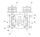
- FIG. 1 is a cross-sectional view of a drive mechanism integrated power generator 1 including a toroidal continuously variable transmission 10 according to an embodiment.
- a drive mechanism integrated power generator 1 (Integrated Drive Generator: hereinafter referred to as “IDG”) is used for an AC power supply of an aircraft, and includes a casing 2 attached to an engine of the aircraft. .
- the casing 2 accommodates an input mechanism 3, a toroidal continuously variable transmission 10 (hereinafter referred to as “transmission”), a power transmission mechanism 4, and a generator 5.
- the toroidal continuously variable transmission 10 does not have to be a part of the drive mechanism-integrated power generator, and the application is not limited to an aircraft.
- the transmission 10 includes a transmission input shaft 11 and a transmission output shaft 12 which are coaxially arranged and are relatively rotatable power transmission shafts (hereinafter, the axes of the shafts 11 and 12 are referred to as “rotation axis A1”). ).
- the transmission input shaft 11 is connected to an engine rotation shaft (not shown) via the input mechanism 3.
- the input mechanism 3 includes a device input shaft 3a to which rotational power from the engine rotation shaft is input, and a gear pair 3b that transmits the rotation of the device input shaft 3a to the transmission input shaft 11.
- the gear pair 3b includes a gear 3ba that rotates integrally with the device input shaft 3a and a gear 3bb that rotates integrally with the transmission input shaft 11.
- the transmission output shaft 12 is connected to the generator input shaft 5a of the generator 5 through a power transmission mechanism 4 (for example, a gear train).
- Rotational power extracted from the engine rotation shaft is input to the transmission input shaft 11 via the input mechanism 3.
- the transmission 10 changes the rotation of the transmission input shaft 11 and outputs it to the transmission output shaft 12.
- the rotational power of the transmission output shaft 12 is transmitted to the generator input shaft 5a via the power transmission mechanism 4.
- the generator input shaft 5a When the generator input shaft 5a is rotationally driven, the generator 5 generates AC power.
- the transmission ratio of the transmission 10 is such that the rotational speed of the generator input shaft 5a is maintained at an appropriate value (a value corresponding to a frequency suitable for the operation of the electrical equipment of the aircraft) regardless of fluctuations in the rotational speed of the engine rotational shaft. Continuously changed.
- the transmission 10 is, for example, a half toroidal type and a double cavity type, and includes two sets of an input disk 13 (first disk) and an output disk 14 (second disk).
- the input disk 13 is fitted to the transmission input shaft 11 so as to rotate integrally with the transmission input shaft 11.
- the output disk 14 is fitted to the transmission output shaft 12 so as to rotate integrally with the transmission output shaft 12.
- the two sets of disks 13 and 14 are adjacently arranged in the direction of the rotation axis A1 so as to rotate around the rotation axis A1.
- the input disk 13 and the output disk 14 are disposed to face each other in the direction of the rotation axis A1 of the transmission 10 and have concave contact surfaces 13a and 14a that face each other.
- the input disk 13 and the output disk 14 form an annular cavity 15 around the rotation axis A1 by the contact surfaces 13a and 14a.
- the transmission is not limited to a double cavity type, and may be a single cavity type, for example.
- the transmission 10 is, for example, a central input type.
- the transmission output shaft 12 is inserted into the transmission input shaft 11 and protrudes from the transmission input shaft 11 to both sides.
- the two input disks 13 are arranged back to back on the transmission input shaft 11.
- the two output disks 14 are arranged outside the two input disks 13 in the direction of the rotation axis A1.
- a gear 3 bb that rotates integrally with the transmission input shaft 11 is provided on the outer peripheral surface of the transmission input shaft 11 and is disposed between the two input disks 13.
- the transmission is not limited to the central input type, and may be a central output type, for example. In the case of the center output type, the pressing device 20 and the cam plate support 28 described later are preferably provided on the input disk 13 side.
- the output disk 14 on one side is fixed to the transmission output shaft 12 by a fixture 16.
- the output disk 14 on the other side is biased toward the input disk 13 by a preload spring 17 (for example, a disc spring), and is biased toward the input disk 13 by the pressing device 20 during rotational driving.
- the pressing device 20 is a loading cam type, and the output disk 14 is connected to the power transmission mechanism 4 via the pressing device 20 so as to be able to transmit power.
- the transmission 10 includes a plurality of power rollers 18 disposed in the cavity 15 and a plurality of trunnions 19 (see FIG. 2) that support the plurality of power rollers 18 so as to be tiltable.
- FIG. 2 is a cross-sectional view of the transmission 10 shown in FIG. 1 as viewed from the direction of the rotation axis A1.
- the trunnion 19 is supported by the casing 2 so as to be tiltable about the tilt axis A2 and displaceable in the direction of the tilt axis A2.
- the tilt axis A2 is in a position twisted with the rotation axis A1.
- the power roller 18 is supported by the trunnion 19 so as to be rotatable around a rotation axis A3 perpendicular to the tilt axis A2.
- the trunnion 19 is rotatably fitted in the through hole 23a of the yoke 23 fixed to the casing 2.
- the trunnion 19 is supported by the casing 2 via the yoke 23 so as to be tiltable about the tilt axis A2 and displaceable in the direction of the tilt axis A2.
- the trunnion 19 is connected to the hydraulic drive mechanism 24.
- the hydraulic drive mechanism 24 is configured to reciprocate the trunnion 19 together with the power roller 18 in the direction of the tilt axis A2.
- tilt angle the angle around the tilt axis A2 of the power roller 18 (hereinafter referred to as “tilt angle”) is changed, and the gear ratio of the transmission 10 tilts. It is changed continuously according to the corner.
- the power roller 18 is sandwiched between the contact surface 13a of the input disk 13 and the contact surface 14a of the output disk 14 so as to tilt about the tilt axis A2, and tilts the rotational driving force of the input disk 13.
- the speed is changed at a gear ratio corresponding to the angle and transmitted to the output disk 14.
- the pressing device 20 presses the output disk 14 toward the input disk 13, and the pressure with which the input disk 13 and the output disk 14 sandwich the power roller 18 increases.
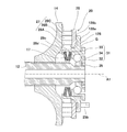
- FIG. 3 is an enlarged view of a main part of the transmission 10 shown in FIG.
- the output disk 14 has a cam surface 14b on the surface opposite to the input disk 13 side.
- the pressing device 20 is disposed so as to be rotatable coaxially with the output disk 14, and includes a cam plate 25 that is an annular plate having a cam surface 25 a facing the cam surface 14 b of the output disk 14, and the output disk 14 and the cam plate 25.
- a roller unit 27 (roller group) composed of a plurality of (for example, three) rollers 26A to 26C arranged in the radial direction perpendicular to the rotation axis A1.
- the cam plate 25 is fitted on a cylindrical portion 28c of a cam plate support 28 described later.
- the cam plate 25 has a dog 25 b that protrudes outward in the direction of the rotation axis A ⁇ b> 1, and the dog 25 b is engaged with the power transmission mechanism 4 so that power can be transmitted.
- the engagement between the cam plate 25 and the power transmission mechanism 4 is not limited to a dog clutch type, but may be an aspect capable of transmitting power, for example, spline connection.
- the cam surfaces 14b and 25a of the output disk 14 and the cam plate 25 facing each other are formed with smooth irregularities in the circumferential direction.
- the rollers 26A to 26C are sandwiched between the rotation axis A1 and the circumferential direction around the rotation axis A1 by the cam surfaces 14b and 25a.
- the cam plate 25 is supported by a cam plate support 28 which is a separate body from the cam plate 25.
- the cam plate 25 and the cam plate support 28 may be integrally formed without being separated from each other.
- the cam plate and the cam plate support may be formed of the same material or different materials.
- the cam plate support 28 is formed of a material having a specific gravity smaller than that of the cam plate 25.
- the cam plate support 28 supports the back surface 25c of the cam plate 25 opposite to the cam surface 25a at the same radial position as a part of the roller unit 27 in the radial direction.
- the cam plate support 28 is interposed between the cam plate 25 and the preload spring 17.
- a preload spring 17 and a thrust bearing 31 are interposed between the cam plate support 28 and the transmission output shaft 12 in the direction of the rotational axis A1. That is, the cam plate support 28 is provided so as to be restricted from moving beyond a predetermined amount in the direction of the rotation axis A1 with respect to the transmission output shaft 12 that is a power transmission shaft.
- the “thrust bearing” means all bearings that can receive a thrust force, and may be a bearing that can receive a radial force as well as a thrust force, and includes, for example, a roller bearing.
- the cam plate support 28 is provided on an arm portion 28a extending in the radial direction along the back surface 25c in a state of being separated from the back surface 25c of the cam plate 25 in the direction of the rotation axis A1, and a cam provided on the radially outer portion of the arm portion 28a.
- An abutting portion 28b that abuts on the back surface 25c of the plate 25 so as to be separable, a cylindrical portion 28c that extends along the rotation axis A1 from the radially inner end of the arm portion 28a toward the output disk 14, and a cylindrical portion 28c.
- a flange portion 28d protruding inward in the radial direction.
- the flange portion 28d is provided at the end portion of the cylindrical portion 28c on the output disk 14 side.
- the flange portion 28d is not necessarily provided at the end portion of the cylindrical portion 28c.
- the flange portion 28d may be provided near the center of the rotation axis A1 of the cylindrical portion 28cb.
- the cylindrical portion 28c can be omitted.
- a flange portion 28d is provided on the radially inner side of the arm portion 28a.
- the contact portion 28 b of the cam plate support 28 is in surface contact with the back surface 25 c of the cam plate 25 at the same radial position as the central position of the roller unit 27.
- the abutting portion 28b of the cam plate support 28 is located on the back surface of the cam plate 25 at a position overlapping with the central roller 26B among the three rollers 26A to 26C aligned in the radial direction when viewed from the direction of the rotation axis A1. 25c.
- the contact portion 28b of the cam plate support 28 is not limited to the shape shown in FIG. Further, the contact portion 28 b of the cam plate support 28 may contact the back surface 25 c of the cam plate 25 at a radial position different from the radial position of the center portion of the roller unit 27.
- a thrust bearing 31 is fitted on the end of the transmission output shaft 12.
- the thrust bearing 31 is interposed between the transmission output shaft 12 and the preload spring 17.
- the thrust bearing 31 includes an inner ring 32, an outer ring 33, and a rolling element 34 interposed between the inner ring 32 and the outer ring 33.
- the inner ring 32 is fitted to the transmission output shaft 12 so that the outward movement of the transmission output shaft 12 in the direction of the rotation axis A1 is restricted.
- the inner ring 32 is positioned on the rotational axis A1 by a nut 35 that is fixed to the end of the transmission output shaft 12 and forms a part of the power transmission shaft.
- the inner ring 32 may be formed integrally with the transmission output shaft 12.
- the position of the outer ring 33 of the thrust bearing 31 in the direction of the rotational axis A1 is at least partially overlapped with the position of the arm portion 28a of the cam plate support 28 in the direction of the rotational axis A1. In this way, a compact configuration is realized in the direction of the rotation axis A1.
- a preload spring 17 is interposed between the cam plate support 28 and the thrust bearing 31.
- the preload spring 17 applies a preload directed toward the input disk 13 to the output disk 14 via the cam plate support 28 and the pressing device 20 in the direction of the rotation axis A1.
- the preload spring 17 is sandwiched between the flange portion 28d of the cam plate support 28 and the outer ring 33 of the thrust bearing 31, and is compressed in the direction of the rotation axis A1.
- the position of the preload spring 17 in the direction of the rotational axis A1 overlaps the position of the rollers 26A to 26C in the direction of the rotational axis A1.
- the cam plate support 28 is disposed so as to be displaceable in the direction of the rotation axis A1 with respect to the thrust bearing 31.
- a gap G is formed between the cam plate support 28 and the thrust bearing 31 in the direction of the rotation axis A1.
- a gap G is formed in the direction of the rotation axis A ⁇ b> 1 between the arm portion 28 a of the cam plate support 28 and the outer ring 33 of the thrust bearing 31.
- the outer ring 33 includes a spring contact portion 33a that contacts the preload spring 17, and a stopper portion 33b that is opposed to the arm portion 28a of the cam plate support 28 with a gap G in the direction of the rotation axis A1.
- the spring contact portion 33 a is fitted into the cylindrical portion 28 c of the cam plate support 28.
- the stopper portion 33b protrudes outward in the radial direction from the outer portion of the spring contact portion 33a in the direction of the rotation axis A1.
- the outer ring 33 has a ring portion 33c that supports the rolling element 34 from the radially outer side, and the spring contact portion 33a is radially inward from the end on the preload spring 17 side of the ring portion 33c.
- the stopper portion 33b protrudes radially outward from the ring portion 33c at a position further away from the preload spring 17 in the direction of the rotation axis A1 than the spring contact portion 33a.
- the stopper portion 33 b is provided at the end portion of the ring portion 33 c on the side opposite to the spring contact portion 33 a, but the end portion of the ring portion 33 c is provided with a gap G from the cam plate 21. May not be provided.
- the length of the gap G in the rotation axis A1 direction is smaller than the deformation amount in the rotation axis A1 direction at the elastic limit of the preload spring 17.
- the preload spring 17 is elastically deformed. While it is inside (before plastic deformation), the cam plate support 28 hits the stopper portion 33b and the gap G disappears.
- the cam plate support 28 suitably receives the reaction force from the rollers 26A to 26C, and the bending of the cam plate 25 is suppressed. Therefore, the contact pressure between the cam plate 25 and the roller unit 27 is kept uniform in the radial direction, and local wear can be prevented, and some of the rollers 26A to 26C are separated from the cam plate 25. Can also be prevented. Further, since the cam plate 25 is supported by the cam plate support 28 from the back surface 25c side, it can be realized with a simple configuration. Accordingly, the toroidal continuously variable transmission 10 including the loading cam type pressing device 20 that can be easily manufactured and has a long life and stable torque transmission performance can be provided.
- the cam plate support 28 is separate from the cam plate 25 and is not fixed to the cam plate 25, and bending stress is hardly transmitted between the cam plate support 28 and the cam plate 25. There is no need to make the cam plate support 28 or the like highly rigid or reinforced, and the weight reduction can be promoted. Further, since the urging force of the preload spring 17 is not transmitted directly to the cam plate 25 but transmitted via the cam plate support 28, the urging force is applied to the back surface 25c of the cam plate 25. Therefore, even when the torque is low, the cam plate 25 is restrained from being tilted by the urging force of the preload spring 17, which can contribute to the uniform contact pressure between the cam plate 25 and the roller unit 27.
- the stopper portion 33b located closer to the abutting portion 28b than the preload spring 17 in the radial direction is provided on the arm of the cam plate support 28.
- the part 28a is abutted and supported. Therefore, the moment that acts on the arm portion 28a at the time of high torque is reduced, and the bending of the arm portion 28a is suppressed. Therefore, an appropriate pressing force can be generated in the pressing device 20 without increasing the thickness of the cam plate support 28.
- the roller unit 27 is a group of rollers composed of a plurality of rollers 26A to 26C arranged in the radial direction, but may be composed of a single roller.
- FIG. 4 is a drawing corresponding to FIG. 3 of the toroidal continuously variable transmission according to the second embodiment.
- the second embodiment is different from the first embodiment in that the cam plate support 128 is in curved contact with the cam plate 25.
- the cam plate support 128 is provided on an arm portion 128a extending in the radial direction along the back surface 25c while being separated from the back surface 25c of the cam plate 25 in the direction of the rotation axis A1, and a cam provided on a radially outer portion of the arm portion 128a And a contact portion 128b that contacts the back surface 25c of the plate 25 so as to be separable.
- the surface of the contact portion 128b that faces the cam plate 25 is a circular arc surface that is convex toward the cam plate 25 in a sectional view including the rotation axis A1 and the rollers 26A to 26C.
- the radial position of the apex of the arc surface of the contact portion 128 b is the same as the radial position of the center of the roller unit 27. According to this configuration, the force acting on the cam plate 25 from the contact portion 128b can be stabilized regardless of the posture of the arm portion 128a of the cam plate support 28. Since other configurations are the same as those of the first embodiment described above, description thereof is omitted.
- FIG. 5 is a drawing corresponding to FIG. 3 of the toroidal continuously variable transmission according to the third embodiment.
- the third embodiment is different from the first embodiment in that the cam plate support 228 is integrated with the cam plate 225.
- the cam plate 225 has the same shape as the cam plate 25 of the first embodiment.
- the cam plate support 228 is spaced from the back surface of the cam plate 225 in the direction of the rotation axis A1 and extends radially along the back surface toward the cam plate 225 from a radially outer portion of the arm portion 228a.
- the cam plate 225 and the cam plate support 228 are fixed to each other by welding or the like, but may be formed as a single body or may be fixed to each other by a fastener. Since other configurations are the same as those of the first embodiment described above, description thereof is omitted.
- FIG. 6 is a drawing corresponding to FIG. 3 of a toroidal continuously variable transmission according to a fourth embodiment.
- the fourth embodiment is different from the first embodiment in that the cam plate support 328 is integrated with the outer ring 333 of the thrust bearing 331.
- the cam plate 325 includes an annular plate portion 325a having a cam surface 325d, a cylindrical portion 325b extending along the rotational axis A1 from the radially inner end of the annular plate portion 325a toward the output disk 14, and a cylindrical portion 325b. And a flange portion 325c protruding radially inward from the output disk 14 side end portion.
- the thrust bearing 331 includes an inner ring 332, an outer ring 333, and a rolling element 334 interposed between the inner ring 332 and the outer ring 333.
- the outer ring 333 is fitted in the cylindrical portion 325b of the cam plate 325.
- the cam plate support 328 is provided on the radially outer side of the arm portion 328a and an arm portion 328a extending in the radial direction along the annular plate portion 325a in a state of being separated from the annular plate portion 325a of the cam plate 325 in the direction of the rotation axis A1. And an abutting portion 328b that abuts on the back surface of the annular plate portion 325a of the cam plate 325 so as to be separable.
- the cam plate support 328 and the outer ring 333 are fixed to each other by welding or the like. However, the cam plate support 328 and the outer ring 333 may be formed as a single body or may be fixed to each other by a fastener. Since other configurations are the same as those of the first embodiment described above, description thereof is omitted.
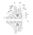
- FIG. 7 is a drawing corresponding to FIG. 3 of a toroidal continuously variable transmission according to a fifth embodiment.
- the cam plate support 428 is integrated with the cam plate 425, and the cam plate 425 is supported by the cam plate support 428 in the radially outer side with respect to the cam plate 425.
- the biased point is different from the first embodiment.
- the cam plate 425 has the same shape as the cam plate 25 of the first embodiment.
- the cam plate support 428 is spaced from the back surface of the cam plate 425 in the direction of the rotation axis A1 and extends radially along the back surface toward the cam plate 425 from the radially outer portion of the arm portion 428a. And a cylindrical portion 428c extending along the rotation axis A1 from the radially inner end of the arm portion 428a toward the output disk 14 side, and a cylindrical portion 428c. And a flange portion 428d protruding inward in the radial direction from the end portion on the output disk 14 side.
- the connecting portion 428 b is connected to the back surface of the cam plate 425 on the radially outer side than the center portion of the roller unit 27.
- the roller 26C is connected to the back surface 25c of the cam plate 25 at a position overlapping with the roller 26C on the radially outer side when viewed from the direction of the rotation axis A1.
- the cam plate 425 and the cam plate support 428 are fixed to each other by welding or the like, but may be formed as a single body or may be fixed to each other by a fastener. According to this configuration, even when a force in the direction of the rotational axis A1 acts on the cam plate 425 from the roller unit 27 due to the cam action of the pressing device 20, the long arm portion 428a in the radial direction bends, Posture change can be suppressed. Since other configurations are the same as those of the first embodiment described above, description thereof is omitted.
- the present invention is not limited to the above-described embodiments, and the configuration can be changed, added, or deleted.
- the above embodiments may be arbitrarily combined with each other.
- some configurations or methods in one embodiment may be applied to other embodiments. It can be arbitrarily extracted separately from the other components in the form.
Abstract
トロイダル無段変速機は、回転軸線を一致させた状態で対向配置された第1ディスク及び第2ディスクと、前記第1ディスクと前記第2ディスクとの間に傾転可能に挟まれたパワーローラと、前記回転軸線周りに回転するカム板と、前記第2ディスクのカム面と前記カム板のカム面との間に挟まれた少なくとも1つのローラからなるローラユニットとを有するローディングカム式の押圧装置と、少なくとも前記ローラユニットの一部の径方向位置と同じ径方向位置において、前記カム板を前記カム面とは反対側の背面を支持するカム板サポートと、を備える。
Description
本発明は、トロイダル無段変速機に関する。
トロイダル無段変速機では、入力ディスクと出力ディスクとの間にパワーローラが挟まれ、パワーローラを傾転させることで変速比が連続的に変更される。特許文献1のトロイダル無段変速機には、ディスクと同軸周りに回転するカム板と、ディスクとカム板との間に挟まれて径方向に並ぶ複数のローラからなるローラ群とを有するローディングカム式の押圧装置が設けられている。ローディングカム式の押圧装置では、伝達トルクが増加するにつれてカム作用によってディスクがカム板から離れるように押圧されることで、入力ディスクと出力ディスクとが互いに近づく向きに付勢され、パワーローラが十分な接触圧で挟まれる。
ところで、高トルク時にローラからの反力によってカム板が反り返るように撓んだ場合には、カム板が径方向内側に位置するローラに集中的に押し当てられることで、ローラの寿命が低下しうると共に、トルク伝達性能も悪化する。その対策として、特許文献1の押圧装置では、カム板及びディスクの少なくとも一方のカム面を、径方向内側に向かってローラから離間する方向に傾くテーパ形状に形成し、径方向内側のローラに常時負担が生じることを防いでいる。
しかし、特許文献1では、低トルク時には径方向外側のローラが荷重を負担し、高トルク時には径方向内側のローラが荷重を負担するように構成されているため、カム板とローラ群と間の接触圧は径方向において不均一なままである。よって、高寿命化及びトルク伝達性能の点で改善の余地がある。また、ディスク及びカム板の製作の際には、カム面のテーパ角を厳密に管理する必要も生じる。
そこで本発明は、容易に製作できて、高寿命でトルク伝達性能が安定したローディングカム式の押圧装置を備えたトロイダル無段変速機を提供することを目的とする。
本発明の一態様に係るトロイダル無段変速機は、回転軸線を一致させた状態で対向配置された第1ディスク及び第2ディスクと、前記第1ディスクと前記第2ディスクとの間に傾転可能に挟まれたパワーローラと、前記回転軸線周りに回転するカム板と、前記第2ディスクのカム面と前記カム板のカム面との間に挟まれた少なくとも1つのローラからなるローラユニットとを有するローディングカム式の押圧装置と、少なくとも前記ローラユニットの一部の径方向位置と同じ径方向位置において、前記カム板を前記カム面とは反対側の背面を支持するカム板サポートと、を備える。
前記構成によれば、カム板サポートがローラユニットからの反力を好適に受け止めてカム板の撓みが抑制される。そのため、カム板とローラユニットとの間の接触圧が径方向において均一に保たれ、局所的な摩耗を防止できると共に、ローラユニットの一部がカム板から離間することも防止できる。また、カム板を背面側からカム板サポートで支持するものであるため、簡素な構成で実現できる。従って、容易に製作できて、高寿命でトルク伝達性能が安定したローディングカム式の押圧装置を備えたトロイダル無段変速機を提供できる。
前記カム板サポートは、前記カム板とは別体であり、前記カム板の前記背面に離間可能に当接していてもよい。
前記構成によれば、カム板サポートがカム板に固定されておらず、カム板サポートとカム板との間で曲げ応力が伝達され難くなるので、曲げ対策としてカム板サポート等を高剛性にしたり補強したりする必要がなくなり、軽量化を促進できる。
前記ローラユニットの前記一部は、前記ローラユニットの中心部であってもよい。
前記構成によれば、カム板とローラユニットとの間の接触圧を好適に均一化できる。
前記カム板を前記ローラユニットに向けて前記回転軸線方向に付勢するプリロードバネを更に備え、前記カム板サポートは、前記カム板と前記プリロードバネとの間に介設されていてもよい。
前記構成によれば、プリロードバネの付勢力がカム板に直接的に伝達されずにカム板サポートを介して伝達されるため、付勢力はカム板の背面に付与される。よって、プリロードバネの付勢力でカム板が傾くことが抑制され、カム板とローラユニットとの間の接触圧の均一化に寄与できる。
本発明によれば、容易に製作できて、高寿命でトルク伝達性能が安定したローディングカム式の押圧装置を備えたトロイダル無段変速機を提供できる。
以下、図面を参照して実施形態を説明する。
(第1実施形態)
図1は、実施形態に係るトロイダル無段変速機10を備える駆動機構一体型発電装置1の断面図である。図1に示すように、駆動機構一体型発電装置1(Integrated Drive Generator:以下、「IDG」という)は、航空機の交流電源に用いられるものであって、航空機のエンジンに取り付けられるケーシング2を備える。ケーシング2には、入力機構3と、トロイダル無段変速機10(以下、「変速機」という)と、動力伝達機構4と、発電機5とが収容されている。なお、トロイダル無段変速機10は、駆動機構一体型発電装置の一部とした構成でなくてもよく、用途も航空機に限られない。
図1は、実施形態に係るトロイダル無段変速機10を備える駆動機構一体型発電装置1の断面図である。図1に示すように、駆動機構一体型発電装置1(Integrated Drive Generator:以下、「IDG」という)は、航空機の交流電源に用いられるものであって、航空機のエンジンに取り付けられるケーシング2を備える。ケーシング2には、入力機構3と、トロイダル無段変速機10(以下、「変速機」という)と、動力伝達機構4と、発電機5とが収容されている。なお、トロイダル無段変速機10は、駆動機構一体型発電装置の一部とした構成でなくてもよく、用途も航空機に限られない。
変速機10は、同軸上に配置されて相対回転可能な動力伝達軸である変速機入力軸11及び変速機出力軸12を備える(以下、各軸11,12の軸線を「回転軸線A1」という)。変速機入力軸11は、入力機構3を介してエンジン回転軸(図示せず)に接続される。入力機構3は、エンジン回転軸からの回転動力が入力される装置入力軸3aと、装置入力軸3aの回転を変速機入力軸11に伝達するギヤ対3bとを含む。ギヤ対3bは、装置入力軸3aと一体回転するギヤ3baと、変速機入力軸11と一体回転するギヤ3bbとを有する。変速機出力軸12は、動力伝達機構4(例えば、ギア列)を介して発電機5の発電機入力軸5aに接続されている。
エンジン回転軸から取り出された回転動力は、入力機構3を介して変速機入力軸11に入力される。変速機10は、変速機入力軸11の回転を変速して変速機出力軸12に出力する。変速機出力軸12の回転動力は、動力伝達機構4を介して発電機入力軸5aに伝達される。発電機入力軸5aが回転駆動されると、発電機5が交流電力を発生する。変速機10の変速比は、エンジン回転軸の回転速度の変動に関わらず発電機入力軸5aの回転速度を適値(航空機の電装品の作動に適した周波数に対応する値)に保つように連続的に変更される。
変速機10は、一例として、ハーフトロイダル型かつダブルキャビティ型であり、二組の入力ディスク13(第1ディスク)及び出力ディスク14(第2ディスク)を備える。入力ディスク13は、変速機入力軸11と一体回転するよう変速機入力軸11に嵌合されている。出力ディスク14は、変速機出力軸12と一体回転するよう変速機出力軸12に嵌合されている。二組のディスク13,14は、回転軸線A1回りに回転するように回転軸線A1方向に隣接配置されている。入力ディスク13と出力ディスク14とは、変速機10の回転軸線A1方向に互いに対向配置され、互いに対向する凹状の接触面13a,14aを有する。入力ディスク13及び出力ディスク14は、接触面13a,14aによって回転軸線A1回りに円環状のキャビティ15を形成する。なお、変速機は、ダブルキャビティ型に限定されず、例えば、シングルキャビティ型でもよい。
変速機10は、一例として、中央入力型である。変速機出力軸12は、変速機入力軸11内に挿通され、変速機入力軸11から両側に突出する。2つの入力ディスク13は、変速機入力軸11上で背中合わせに配置されている。2つの出力ディスク14は、2つの入力ディスク13の回転軸線A1方向の外側に配置されている。変速機入力軸11と一体回転するギヤ3bbは、変速機入力軸11の外周面上に設けられ、2つの入力ディスク13間に配置されている。なお、変速機は、中央入力型に限定されず、例えば、中央出力型でもよい。中央出力型の場合には、後述する押圧装置20及びカム板サポート28は、入力ディスク13側に設けられるとよい。
一方側の出力ディスク14は、固定具16によって変速機出力軸12に固定されている。他方側の出力ディスク14は、プリロードバネ17(例えば、皿バネ)によって入力ディスク13に向けて付勢され、かつ、回転駆動時には押圧装置20によって入力ディスク13に向けて付勢される。押圧装置20は、ローディングカム式であり、出力ディスク14は、押圧装置20を介して動力伝達機構4に動力伝達可能に接続されている。変速機10は、キャビティ15内に配置された複数のパワーローラ18と、複数のパワーローラ18をそれぞれ傾転可能に支持する複数のトラニオン19(図2参照)とを備える。
図2は、図1に示す変速機10の回転軸線A1方向から見た断面図である。図2に示すように、トラニオン19は、傾転軸線A2回りに傾転可能かつ傾転軸線A2方向に変位可能な状態でケーシング2に支持されている。傾転軸線A2は、回転軸線A1とねじれの位置にある。パワーローラ18は、傾転軸線A2に対して垂直な回転軸線A3回りに回転自在にトラニオン19に支持されている。
トラニオン19は、ケーシング2に固定されたヨーク23の貫通穴23aに回転自在に嵌め込まれる。トラニオン19は、ヨーク23を介して、傾転軸線A2回りに傾転可能かつ傾転軸線A2方向に変位可能にケーシング2に支持されている。トラニオン19は、油圧駆動機構24に接続されている。油圧駆動機構24は、トラニオン19をパワーローラ18とともに傾転軸線A2方向に往復変位させるよう構成されている。
図1及び2に示すように、入力ディスク13が回転駆動されると、パワーローラ18を介して出力ディスク14が回転駆動され、変速機出力軸12が回転駆動される。トラニオン19及びパワーローラ18が傾転軸線A2方向に変位すると、パワーローラ18の傾転軸線A2回りの角度(以下、「傾転角」という)が変更され、変速機10の変速比が傾転角に応じて連続的に変更される。
パワーローラ18は、傾転軸線A2回りに傾転可能な状態で、入力ディスク13の接触面13aと出力ディスク14の接触面14aとの間に挟まれ、入力ディスク13の回転駆動力を傾転角に応じた変速比で変速して出力ディスク14に伝達する。出力ディスク14の回転トルクが増加すると、押圧装置20によって出力ディスク14が入力ディスク13に近づく向きに押圧され、入力ディスク13及び出力ディスク14がパワーローラ18を挟む圧力が増加する。
図3は、図1に示す変速機10の要部の拡大図である。図3に示すように、出力ディスク14は、入力ディスク13側とは反対側の面にカム面14bを有する。押圧装置20は、出力ディスク14と同軸上に回転可能に配置され、出力ディスク14のカム面14bに対向するカム面25aを有する環状板であるカム板25と、出力ディスク14とカム板25との間に挟まれて回転軸線A1と直交する径方向に並ぶ複数(例えば、3つ)のローラ26A~Cからなるローラユニット27(ローラ群)とを備える。カム板25は、後述するカム板サポート28の筒部28cに外嵌されている。カム板25は、回転軸線A1方向の外方に突出するドッグ25bを有し、そのドッグ25bが動力伝達機構4に動力伝達可能に係合されている。なお、カム板25と動力伝達機構4との間の係合は、ドッグクラッチ形式でなくても動力伝達可能な態様であればよく、例えば、スプライン接続でもよい。
出力ディスク14及びカム板25の互いに対向するカム面14b,25aには、周方向に滑らかな凹凸が形成されている。ローラ26A~Cは、カム面14b,25aによって回転軸線A1方向と回転軸線A1回りの周方向とに挟まれ、出力ディスク14及びカム板25の回転トルクが増加すると、カム作用によって出力ディスク14がカム板25から離れる向きに押圧される。
カム板25は、カム板25とは別体であるカム板サポート28により支持されている。なお、カム板25とカム板サポート28とは、互いに別体とせずに一体で形成してもよい。カム板とカム板サポートとは、互いに同一材料で形成してもよいし別材料で形成してもよい。別材料とする場合には、カム板25よりも比重が小さい材料でカム板サポート28が形成される。カム板サポート28は、ローラユニット27の一部の径方向位置と同じ径方向位置において、カム板25のカム面25aとは反対側の背面25cを支持する。カム板サポート28は、カム板25とプリロードバネ17との間に介設されている。カム板サポート28と変速機出力軸12との間には、回転軸線A1方向において、プリロードバネ17及びスラスト軸受31が介設されている。即ち、カム板サポート28は、動力伝達軸である変速機出力軸12に対して回転軸線A1方向の外方への所定以上の移動が規制されるように設けられている。なお、「スラスト軸受」は、スラスト力を受け得る全ての軸受を意味し、スラスト力とともにラジアル力を受け得る軸受でもよく、例えば、ころ軸受なども含む。
カム板サポート28は、カム板25の背面25cから回転軸線A1方向に離間した状態で背面25cに沿って径方向に延びるアーム部28aと、アーム部28aの径方向外側の部分に設けられてカム板25の背面25cに離間可能に当接する当接部28bと、アーム部28aの径方向内側の端部から出力ディスク14側に向けて回転軸線A1に沿って延びる筒部28cと、筒部28cから径方向内方に突出する鍔部28dとを有する。本実施形態では、鍔部28dは筒部28cの出力ディスク14側の端部に設けられている。ただし、鍔部28dは、筒部28cの端部に設けられている必要はない。鍔部28dは、筒部28cbの回転軸線A1の中央付近に設けられていてもよい。また、筒部28cを省略することも可能である。この場合、アーム部28aの径方向内側に、鍔部28dが設けられる。
カム板サポート28の当接部28bは、ローラユニット27の中心部の径方向位置と同じ径方向位置において、カム板25の背面25cに面接触している。本実施形態では、カム板サポート28の当接部28bは、径方向に並んだ3つのローラ26A~Cのうち中央のローラ26Bと回転軸線A1方向から見て重なる位置において、カム板25の背面25cに当接している。なお、カム板サポート28の当接部28bは、図3の形状に限られず、例えば、カム板25の背面25cに線接触する形状としてもよい。また、カム板サポート28の当接部28bは、ローラユニット27の中心部の径方向位置とは異なる径方向位置において、カム板25の背面25cに当接してもよい。
変速機出力軸12の端部には、スラスト軸受31が外嵌されている。スラスト軸受31は、変速機出力軸12とプリロードバネ17との間に介設されている。スラスト軸受31は、内輪32と、外輪33と、内輪32と外輪33との間に介在する転動体34とを有する。内輪32は、変速機出力軸12に対して回転軸線A1方向の外方への移動が規制されるように変速機出力軸12に嵌合されている。一例として、内輪32は、変速機出力軸12の端部に固定されて動力伝達軸の一部をなすナット35によって回転軸線A1に位置決めされている。なお、内輪32は、変速機出力軸12に一体に形成されてもよい。スラスト軸受31の外輪33の回転軸線A1方向の位置は、カム板サポート28のアーム部28aの回転軸線A1方向の位置と少なくとも一部が重なっている。こうすれば、回転軸線A1方向にコンパクトな構成が実現される。
カム板サポート28とスラスト軸受31との間には、プリロードバネ17が介設されている。プリロードバネ17は、回転軸線A1方向において、カム板サポート28及び押圧装置20を介して出力ディスク14に入力ディスク13側に向けたプリロードを付与する。具体的には、プリロードバネ17は、カム板サポート28の鍔部28dとスラスト軸受31の外輪33との間に挟まれて、回転軸線A1方向に圧縮されている。プリロードバネ17の回転軸線A1方向の位置は、ローラ26A~Cの回転軸線A1方向の位置と重なっている。
カム板サポート28は、スラスト軸受31に対して回転軸線A1方向に変位可能に配置されており、カム板サポート28とスラスト軸受31との間には、回転軸線A1方向に隙間Gが形成されている。本実施形態では、カム板サポート28のアーム部28aとスラスト軸受31の外輪33との間に、回転軸線A1方向に隙間Gが形成されている。外輪33は、プリロードバネ17に当接するバネ当接部33aと、カム板サポート28のアーム部28aと隙間Gをあけて回転軸線A1方向に対向するストッパ部33bとを有する。バネ当接部33aは、カム板サポート28の筒部28cに内嵌されている。ストッパ部33bは、バネ当接部33aの回転軸線A1方向の外側の部分から径方向外方に突出している。
本実施形態では、外輪33は、転動体34を径方向外側から支持する輪部33cを有し、バネ当接部33aは、輪部33cのうちプリロードバネ17側の端部から径方向内方に突出し、ストッパ部33bは、バネ当接部33aよりもプリロードバネ17から回転軸線A1方向に離れた位置で輪部33cから径方向外方に突出する。図3の例では、ストッパ部33bは、輪部33cのうちバネ当接部33aとは反対側の端部に設けられるが、カム板21と隙間Gをあけていれば輪部33cの端部に設けられなくてもよい。
出力ディスク14及び押圧装置20が非回転の状態において、隙間Gの回転軸線A1方向の長さは、プリロードバネ17の弾性限度における回転軸線A1方向の変形量よりも小さい。出力ディスク14及び押圧装置20が回転して、押圧装置20のカム作用により出力ディスク14とカム板25とが互いに離れるように回転軸線A1方向に相対変位し始めると、プリロードバネ17が弾性変形範囲内にあるうちに(塑性変形する前に)カム板サポート28がストッパ部33bに当たって隙間Gが無くなる。
そして、押圧装置20のカム作用によりローラユニット27からカム板25に回転軸線A1方向の力が作用すると、カム板25は、回転軸線A1方向においてプリロードバネ17及びスラスト軸受31に支持されたカム板サポート28から抗力を受ける。その際、カム板サポート28の当接部28bは、ローラユニット27の中心部の径方向位置と同じ径方向位置において、カム板25の背面25cに当接しているので、ローラユニット27からカム板25に伝わる力の作用位置と、カム板サポート28からカム板25に伝わる抗力の作用位置とが、径方向にずれることが防がれる。そのため、高トルク時にカム板25の外周部が反り返るように撓むことが抑制され、ローラ26A~Cとカム板25との間に作用する力が径方向に適切に分散される。
以上に説明した構成によれば、カム板サポート28がローラ26A~Cからの反力を好適に受け止めてカム板25の撓みが抑制される。そのため、カム板25とローラユニット27との間の接触圧が径方向において均一に保たれ、局所的な摩耗を防止できると共に、ローラ26A~Cのうち一部のローラがカム板25から離間することも防止できる。また、カム板25を背面25c側からカム板サポート28で支持するものであるため、簡素な構成で実現できる。従って、容易に製作できて、高寿命でトルク伝達性能が安定したローディングカム式の押圧装置20を備えたトロイダル無段変速機10を提供できる。
また、カム板サポート28は、カム板25とは別体でカム板25に固定されておらず、カム板サポート28とカム板25との間で曲げ応力が伝達され難くなるので、曲げ対策としてカム板サポート28等を高剛性にしたり補強したりする必要がなくなり、軽量化を促進できる。また、プリロードバネ17の付勢力はカム板25に直接的に伝達されずにカム板サポート28を介して伝達される構成であるため、当該付勢力はカム板25の背面25cに付与される。よって、低トルク時にもプリロードバネ17の付勢力でカム板25が傾くことが抑制され、カム板25とローラユニット27との間の接触圧の均一化に寄与できる。
また、出力ディスク14及び押圧装置20の回転トルクが増加して隙間Gが無くなると、径方向においてプリロードバネ17よりも当接部28bに近い位置にあるストッパ部33bが、カム板サポート28のアーム部28aを当接支持する。そのため、高トルク時にアーム部28aに作用するモーメントが低減され、アーム部28aの撓みが抑制される。よって、カム板サポート28を厚肉化することなく、押圧装置20に適切な押圧力を生じさせることができる。また、カム板サポート28の存在によりカム板25を厚肉化せず済むので、カム板サポート28をカム板25よりも比重が小さい材料で形成すれば、全体として重量増加を抑制できる。なお、本実施形態では、ローラユニット27は、径方向に並ぶ複数のローラ26A~Cからなるローラ群としたが、単一のローラからなるものでもよい。
(第2実施形態)
図4は、第2実施形態に係るトロイダル無段変速機の図3相当の図面である。図4に示すように、第2実施形態では、カム板サポート128がカム板25に対して曲面接触している点が第1実施形態と異なる。カム板サポート128は、カム板25の背面25cから回転軸線A1方向に離間した状態で背面25cに沿って径方向に延びるアーム部128aと、アーム部128aの径方向外側の部分に設けられてカム板25の背面25cに離間可能に当接する当接部128bとを有する。
図4は、第2実施形態に係るトロイダル無段変速機の図3相当の図面である。図4に示すように、第2実施形態では、カム板サポート128がカム板25に対して曲面接触している点が第1実施形態と異なる。カム板サポート128は、カム板25の背面25cから回転軸線A1方向に離間した状態で背面25cに沿って径方向に延びるアーム部128aと、アーム部128aの径方向外側の部分に設けられてカム板25の背面25cに離間可能に当接する当接部128bとを有する。
当接部128bのカム板25に対向する面は、回転軸線A1及びローラ26A~Cを含む断面視で、カム板25に向けて凸な円弧面である。当接部128bの円弧面の頂点の径方向位置は、ローラユニット27の中心の径方向位置と同じである。この構成によれば、カム板サポート28のアーム部128aの姿勢に関わらず、当接部128bからカム板25に作用する力を安定化させることができる。なお、他の構成は前述した第1実施形態と同様であるため説明を省略する。
(第3実施形態)
図5は、第3実施形態に係るトロイダル無段変速機の図3相当の図面である。図5に示すように、第3実施形態では、カム板サポート228がカム板225と一体である点が第1実施形態と異なる。カム板225は、第1実施形態のカム板25と同じ形状である。カム板サポート228は、カム板225の背面から回転軸線A1方向に離間した状態で当該背面に沿って径方向に延びるアーム部228aと、アーム部228aの径方向外側の部分からカム板225に向けて突出してカム板225の背面に固定された連結部228bと、アーム部228aの径方向内側の端部から出力ディスク14側に向けて回転軸線A1に沿って延びる筒部228cと、筒部228cの出力ディスク14側の端部から径方向内方に突出する鍔部228dとを有する。カム板225とカム板サポート228とは、互いに溶接等で固定されているが、一体物として形成されてもよいし、締結具により互いに固定されてもよい。なお、他の構成は前述した第1実施形態と同様であるため説明を省略する。
図5は、第3実施形態に係るトロイダル無段変速機の図3相当の図面である。図5に示すように、第3実施形態では、カム板サポート228がカム板225と一体である点が第1実施形態と異なる。カム板225は、第1実施形態のカム板25と同じ形状である。カム板サポート228は、カム板225の背面から回転軸線A1方向に離間した状態で当該背面に沿って径方向に延びるアーム部228aと、アーム部228aの径方向外側の部分からカム板225に向けて突出してカム板225の背面に固定された連結部228bと、アーム部228aの径方向内側の端部から出力ディスク14側に向けて回転軸線A1に沿って延びる筒部228cと、筒部228cの出力ディスク14側の端部から径方向内方に突出する鍔部228dとを有する。カム板225とカム板サポート228とは、互いに溶接等で固定されているが、一体物として形成されてもよいし、締結具により互いに固定されてもよい。なお、他の構成は前述した第1実施形態と同様であるため説明を省略する。
(第4実施形態)
図6は、第4実施形態に係るトロイダル無段変速機の図3相当の図面である。図6に示すように、第4実施形態では、カム板サポート328がスラスト軸受331の外輪333と一体である点が第1実施形態と異なる。カム板325は、カム面325dを有する環状板部325aと、環状板部325aの径方向内側の端部から出力ディスク14側に向けて回転軸線A1に沿って延びる筒部325bと、筒部325bの出力ディスク14側の端部から径方向内方に突出する鍔部325cとを有する。スラスト軸受331は、内輪332と、外輪333と、内輪332と外輪333との間に介在する転動体334とを有する。外輪333は、カム板325の筒部325bに内嵌されている。
図6は、第4実施形態に係るトロイダル無段変速機の図3相当の図面である。図6に示すように、第4実施形態では、カム板サポート328がスラスト軸受331の外輪333と一体である点が第1実施形態と異なる。カム板325は、カム面325dを有する環状板部325aと、環状板部325aの径方向内側の端部から出力ディスク14側に向けて回転軸線A1に沿って延びる筒部325bと、筒部325bの出力ディスク14側の端部から径方向内方に突出する鍔部325cとを有する。スラスト軸受331は、内輪332と、外輪333と、内輪332と外輪333との間に介在する転動体334とを有する。外輪333は、カム板325の筒部325bに内嵌されている。
カム板サポート328は、カム板325の環状板部325aから回転軸線A1方向に離間した状態で環状板部325aに沿って径方向に延びるアーム部328aと、アーム部328aの径方向外側に設けられてカム板325の環状板部325aの背面に離間可能に当接する当接部328bとを有する。カム板サポート328と外輪333とは、互いに溶接等で固定されているが、一体物として形成されてもよいし、締結具により互いに固定されてもよい。なお、他の構成は前述した第1実施形態と同様であるため説明を省略する。
(第5実施形態)
図7は、第5実施形態に係るトロイダル無段変速機の図3相当の図面である。図7に示すように、第5実施形態では、カム板サポート428がカム板425と一体であり、かつ、カム板サポート428によるカム板425の支持位置がカム板425に対して径方向外側に偏倚している点が第1実施形態と異なる。カム板425は、第1実施形態のカム板25と同じ形状である。
図7は、第5実施形態に係るトロイダル無段変速機の図3相当の図面である。図7に示すように、第5実施形態では、カム板サポート428がカム板425と一体であり、かつ、カム板サポート428によるカム板425の支持位置がカム板425に対して径方向外側に偏倚している点が第1実施形態と異なる。カム板425は、第1実施形態のカム板25と同じ形状である。
カム板サポート428は、カム板425の背面から回転軸線A1方向に離間した状態で当該背面に沿って径方向に延びるアーム部428aと、アーム部428aの径方向外側の部分からカム板425に向けて突出してカム板425の背面に固定された連結部428bと、アーム部428aの径方向内側の端部から出力ディスク14側に向けて回転軸線A1に沿って延びる筒部428cと、筒部428cの出力ディスク14側の端部から径方向内方に突出する鍔部428dとを有する。連結部428bは、ローラユニット27の中心部よりも径方向外方において、カム板425の背面に連結されている。
具体的には、径方向に並んだ3つのローラ26A~Cのうち径方向外側のローラ26Cと回転軸線A1方向から見て重なる位置において、カム板25の背面25cに連結している。カム板425とカム板サポート428とは、互いに溶接等で固定されているが、一体物として形成されてもよいし、締結具により互いに固定されてもよい。この構成によれば、押圧装置20のカム作用によりローラユニット27からカム板425に回転軸線A1方向の力が作用しても、径方向に長いアーム部428aが撓むことで、カム板425の姿勢変化を抑制することができる。なお、他の構成は前述した第1実施形態と同様であるため説明を省略する。
なお、本発明は前述した各実施形態に限定されるものではなく、その構成を変更、追加、又は削除することができる。前記各実施形態は互いに任意に組み合わせてもよく、例えば1つの実施形態中の一部の構成又は方法を他の実施形態に適用してもよく、実施形態中の一部の構成は、その実施形態中の他の構成から分離して任意に抽出可能である。
10 トロイダル無段変速機
13 入力ディスク(第1ディスク)
14 出力ディスク(第2ディスク)
17 プリロードバネ
18 パワーローラ
20 押圧装置
25,225,325,425 カム板
26A~C ローラ
27 ローラユニット
28,128,228,328,428 カム板サポート
31,331 スラスト軸受
A1 回転軸線
13 入力ディスク(第1ディスク)
14 出力ディスク(第2ディスク)
17 プリロードバネ
18 パワーローラ
20 押圧装置
25,225,325,425 カム板
26A~C ローラ
27 ローラユニット
28,128,228,328,428 カム板サポート
31,331 スラスト軸受
A1 回転軸線
Claims (4)
- 回転軸線を一致させた状態で対向配置された第1ディスク及び第2ディスクと、
前記第1ディスクと前記第2ディスクとの間に傾転可能に挟まれたパワーローラと、
前記回転軸線周りに回転するカム板と、前記第2ディスクのカム面と前記カム板のカム面との間に挟まれた少なくとも1つのローラからなるローラユニットとを有するローディングカム式の押圧装置と、
少なくとも前記ローラユニットの一部の径方向位置と同じ径方向位置において、前記カム板を前記カム面とは反対側の背面を支持するカム板サポートと、を備える、トロイダル無段変速機。 - 前記カム板サポートは、前記カム板とは別体であり、前記カム板の前記背面に離間可能に当接している、請求項1に記載のトロイダル無段変速機。
- 前記ローラユニットの前記一部は、前記ローラユニットの中心部である、請求項1又は2に記載のトロイダル無段変速機。
- 前記カム板を前記ローラユニットに向けて前記回転軸線方向に付勢するプリロードバネを更に備え、
前記カム板サポートは、前記カム板と前記プリロードバネとの間に介設されている、請求項1乃至3のいずれか1項に記載のトロイダル無段変速機。
Priority Applications (2)
| Application Number | Priority Date | Filing Date | Title |
|---|---|---|---|
| US16/345,051 US11067154B2 (en) | 2016-10-27 | 2017-10-24 | Toroidal continuously variable transmission |
| EP17866028.8A EP3534036B1 (en) | 2016-10-27 | 2017-10-24 | Toroidal continuously variable transmission |
Applications Claiming Priority (2)
| Application Number | Priority Date | Filing Date | Title |
|---|---|---|---|
| JP2016-210206 | 2016-10-27 | ||
| JP2016210206A JP6748558B2 (ja) | 2016-10-27 | 2016-10-27 | トロイダル無段変速機 |
Publications (1)
| Publication Number | Publication Date |
|---|---|
| WO2018079505A1 true WO2018079505A1 (ja) | 2018-05-03 |
Family
ID=62024956
Family Applications (1)
| Application Number | Title | Priority Date | Filing Date |
|---|---|---|---|
| PCT/JP2017/038241 WO2018079505A1 (ja) | 2016-10-27 | 2017-10-24 | トロイダル無段変速機 |
Country Status (4)
| Country | Link |
|---|---|
| US (1) | US11067154B2 (ja) |
| EP (1) | EP3534036B1 (ja) |
| JP (1) | JP6748558B2 (ja) |
| WO (1) | WO2018079505A1 (ja) |
Families Citing this family (3)
| Publication number | Priority date | Publication date | Assignee | Title |
|---|---|---|---|---|
| JP6756580B2 (ja) * | 2016-10-27 | 2020-09-16 | 川崎重工業株式会社 | トロイダル無段変速機 |
| JP6748558B2 (ja) * | 2016-10-27 | 2020-09-02 | 川崎重工業株式会社 | トロイダル無段変速機 |
| WO2021220903A1 (ja) * | 2020-04-27 | 2021-11-04 | 川崎重工業株式会社 | トロイダル無段変速機 |
Citations (2)
| Publication number | Priority date | Publication date | Assignee | Title |
|---|---|---|---|---|
| JP2005214373A (ja) | 2004-02-02 | 2005-08-11 | Nsk Ltd | トロイダル型無段変速機 |
| JP2015075185A (ja) * | 2013-10-10 | 2015-04-20 | 日本精工株式会社 | シングルキャビティ式トロイダル型無段変速機 |
Family Cites Families (14)
| Publication number | Priority date | Publication date | Assignee | Title |
|---|---|---|---|---|
| US2292066A (en) * | 1939-11-17 | 1942-08-04 | Richard T Erban | Friction transmission mechanism |
| US3163051A (en) * | 1963-06-19 | 1964-12-29 | Excelermatic | Roller construction for toroidal transmissions |
| JPH0672655B2 (ja) * | 1988-12-16 | 1994-09-14 | 日産自動車株式会社 | トロイダル型無段変速機 |
| JPH0672656B2 (ja) * | 1989-03-31 | 1994-09-14 | 日産自動車株式会社 | トロイダル無段変速機のローディングカム装置 |
| JP4254051B2 (ja) * | 2000-11-15 | 2009-04-15 | 日本精工株式会社 | トロイダル型無段変速機 |
| JP2003028258A (ja) * | 2001-07-19 | 2003-01-29 | Nsk Ltd | トロイダル型無段変速機 |
| JP3775660B2 (ja) * | 2002-01-17 | 2006-05-17 | 日本精工株式会社 | トロイダル型無段変速機のローディングカム装置の保持器 |
| JP2004084913A (ja) * | 2002-08-29 | 2004-03-18 | Nsk Ltd | トロイダル型無段変速機 |
| US7563192B2 (en) * | 2003-06-27 | 2009-07-21 | Nsk Ltd. | Toroidal-type continuously variable transmission |
| EP2677198B1 (en) * | 2011-02-03 | 2018-04-04 | NSK Ltd. | Toroidal continuously variable transmission |
| JP6427899B2 (ja) * | 2013-08-02 | 2018-11-28 | 日本精工株式会社 | トロイダル型無段変速機 |
| WO2015151932A1 (ja) * | 2014-04-02 | 2015-10-08 | 日本精工株式会社 | トロイダル無段変速機 |
| JP6756580B2 (ja) * | 2016-10-27 | 2020-09-16 | 川崎重工業株式会社 | トロイダル無段変速機 |
| JP6748558B2 (ja) * | 2016-10-27 | 2020-09-02 | 川崎重工業株式会社 | トロイダル無段変速機 |
-
2016
- 2016-10-27 JP JP2016210206A patent/JP6748558B2/ja active Active
-
2017
- 2017-10-24 EP EP17866028.8A patent/EP3534036B1/en active Active
- 2017-10-24 WO PCT/JP2017/038241 patent/WO2018079505A1/ja unknown
- 2017-10-24 US US16/345,051 patent/US11067154B2/en active Active
Patent Citations (2)
| Publication number | Priority date | Publication date | Assignee | Title |
|---|---|---|---|---|
| JP2005214373A (ja) | 2004-02-02 | 2005-08-11 | Nsk Ltd | トロイダル型無段変速機 |
| JP2015075185A (ja) * | 2013-10-10 | 2015-04-20 | 日本精工株式会社 | シングルキャビティ式トロイダル型無段変速機 |
Also Published As
| Publication number | Publication date |
|---|---|
| JP6748558B2 (ja) | 2020-09-02 |
| EP3534036A4 (en) | 2020-03-18 |
| JP2018071610A (ja) | 2018-05-10 |
| US20190277374A1 (en) | 2019-09-12 |
| EP3534036B1 (en) | 2021-07-21 |
| US11067154B2 (en) | 2021-07-20 |
| EP3534036A1 (en) | 2019-09-04 |
Similar Documents
| Publication | Publication Date | Title |
|---|---|---|
| CN112334675B (zh) | 离合装置 | |
| WO2018079505A1 (ja) | トロイダル無段変速機 | |
| JP6117991B2 (ja) | トロイダル無段変速機 | |
| WO2018079506A1 (ja) | トロイダル無段変速機 | |
| JP3651929B2 (ja) | トロイダル型無段変速機 | |
| JP6603404B2 (ja) | トロイダル無段変速機 | |
| US20220333671A1 (en) | Toroidal continuously variable transmission | |
| JP6331449B2 (ja) | トロイダル型無段変速機 | |
| JP4998081B2 (ja) | 円錐摩擦リング式無段変速装置 | |
| JP5120666B2 (ja) | トロイダル型無段変速機 | |
| JP7449769B2 (ja) | トロイダル無段変速機 | |
| JP7486341B2 (ja) | トロイダル無段変速機 | |
| JP2006057804A (ja) | 逆入力遮断装置 | |
| JP2019163789A (ja) | 動力伝達装置 | |
| WO2021220903A1 (ja) | トロイダル無段変速機 | |
| WO2019111314A1 (ja) | ローディングカム装置 | |
| JP5488492B2 (ja) | 無段変速機 | |
| JP6766382B2 (ja) | トロイダル型無段変速機 | |
| EP2199633B1 (en) | Input shaft support structure | |
| WO2018061943A1 (ja) | 逆入力遮断装置 | |
| JP2013117237A (ja) | トロイダル型無段変速機 | |
| JP4710726B2 (ja) | トロイダル型無段変速機 | |
| JPH11223256A (ja) | 摩擦変速機 | |
| JP2002081518A (ja) | 摩擦ローラ式変速機 |
Legal Events
| Date | Code | Title | Description |
|---|---|---|---|
| 121 | Ep: the epo has been informed by wipo that ep was designated in this application |
Ref document number: 17866028 Country of ref document: EP Kind code of ref document: A1 |
|
| NENP | Non-entry into the national phase |
Ref country code: DE |
|
| ENP | Entry into the national phase |
Ref document number: 2017866028 Country of ref document: EP Effective date: 20190527 |