WO2018079374A1 - 駆動装置 - Google Patents
駆動装置 Download PDFInfo
- Publication number
- WO2018079374A1 WO2018079374A1 PCT/JP2017/037687 JP2017037687W WO2018079374A1 WO 2018079374 A1 WO2018079374 A1 WO 2018079374A1 JP 2017037687 W JP2017037687 W JP 2017037687W WO 2018079374 A1 WO2018079374 A1 WO 2018079374A1
- Authority
- WO
- WIPO (PCT)
- Prior art keywords
- rotation
- connecting member
- rotating
- rotating member
- gear
- Prior art date
- Legal status (The legal status is an assumption and is not a legal conclusion. Google has not performed a legal analysis and makes no representation as to the accuracy of the status listed.)
- Ceased
Links
Images








Classifications
-
- E—FIXED CONSTRUCTIONS
- E06—DOORS, WINDOWS, SHUTTERS, OR ROLLER BLINDS IN GENERAL; LADDERS
- E06B—FIXED OR MOVABLE CLOSURES FOR OPENINGS IN BUILDINGS, VEHICLES, FENCES OR LIKE ENCLOSURES IN GENERAL, e.g. DOORS, WINDOWS, BLINDS, GATES
- E06B9/00—Screening or protective devices for wall or similar openings, with or without operating or securing mechanisms; Closures of similar construction
- E06B9/56—Operating, guiding or securing devices or arrangements for roll-type closures; Spring drums; Tape drums; Counterweighting arrangements therefor
- E06B9/68—Operating devices or mechanisms, e.g. with electric drive
- E06B9/70—Operating devices or mechanisms, e.g. with electric drive comprising an electric motor positioned outside the roller
-
- E—FIXED CONSTRUCTIONS
- E06—DOORS, WINDOWS, SHUTTERS, OR ROLLER BLINDS IN GENERAL; LADDERS
- E06B—FIXED OR MOVABLE CLOSURES FOR OPENINGS IN BUILDINGS, VEHICLES, FENCES OR LIKE ENCLOSURES IN GENERAL, e.g. DOORS, WINDOWS, BLINDS, GATES
- E06B9/00—Screening or protective devices for wall or similar openings, with or without operating or securing mechanisms; Closures of similar construction
- E06B9/56—Operating, guiding or securing devices or arrangements for roll-type closures; Spring drums; Tape drums; Counterweighting arrangements therefor
- E06B9/68—Operating devices or mechanisms, e.g. with electric drive
- E06B9/74—Operating devices or mechanisms, e.g. with electric drive adapted for selective electrical or manual operation
Definitions
- the present invention relates to a drive device.
- the shutter can be manually opened and closed, and a mechanical lock is set using the clutch mechanism.
- a drive device that can open and close the shutter electrically.
- the conventional drive device has a problem that the cost of the clutch mechanism for releasing and setting the mechanical lock is high.
- the present invention has been made in view of the above, and an object of the present invention is to provide a drive device that can release and set a mechanical lock by a drive unit while suppressing cost.
- a driving apparatus generates a driving force that rotationally drives a driven part, and is provided with a driving part provided outside the driven part.
- a gear group that transmits the driving force generated by the driving unit to the driven unit, and a predetermined group of gears included in the gear group, provided between the gear group and the driven unit.
- a switching unit that can switch a connection state between the predetermined gear and the connecting member by an external force applied in a direction orthogonal to the rotation axis of the driven unit.
- the mechanical lock can be released and set by the drive unit while suppressing the cost.
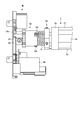
- FIG. 1 is a schematic diagram illustrating a configuration of the entire shutter device including the driving device according to the embodiment.
- FIG. 2 is a perspective view of the connecting member and the rotation mechanism.
- FIG. 3 is a front view of the connecting member and the rotation mechanism.
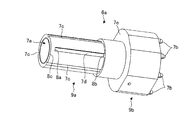
- FIG. 4 is a perspective view of the first connecting member.
- FIG. 5 is a perspective view of the second connecting member.
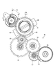
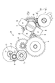
- FIG. 6 is a front view of the transmission device according to the embodiment.
- FIG. 7 is a rear view of the transmission device according to the embodiment.
- FIG. 8 is a plan perspective view of the pressing member.
- FIG. 9 is a bottom perspective view of the pressing member.
- FIG. 10 is a perspective view of the rotating member.
- FIG. 11A is a plan perspective view of the urging portion.
- FIG. 11B is a plan perspective view of the first rotating member.
- FIG. 11C is a plan perspective view of the second rotating member.
- FIG. 11D is a bottom perspective view of the second rotating member.
- FIG. 11E is a plan perspective view of the fixing member.
- FIG. 12 is a diagram illustrating an example of a positional relationship between two gears.
- FIG. 13 is a diagram for describing a method of switching from the first state to the second state using the switching unit.
- FIG. 14 is a diagram illustrating a state (first state) before the second connecting member according to the embodiment moves to the first connecting member side.
- FIG. 15 is a diagram illustrating a state (second state) after the second connecting member according to the embodiment has moved to the first connecting member side.
- FIG. 1 is a schematic diagram illustrating a configuration of the entire shutter device including the driving device according to the embodiment.
- the shutter device 1 according to the embodiment includes a shutter 2, a mounting member 3, a driving device 4, and a rotation mechanism 5.
- the shutter 2 includes a plurality of sluds 2a.
- the attachment member 3 is a member for attaching the shutter device 1 to a wall of a house.
- the shutter device 1 is attached to the wall by fixing the attachment member 3 to the wall with a fixing means such as a screw in a state where a predetermined surface of the attachment member 3 is pressed against the wall.
- the driving device 4 generates a driving force for rotating the rotating mechanism 5 and transmits the generated driving force to the rotating mechanism 5 to drive the rotating mechanism 5 to rotate.
- the drive device 4 includes a motor 4a, a transmission device 4b, a connecting member 4c (see FIG. 2), and a switching unit 25 (see FIG. 6).
- the motor 4a is supplied with electric power from a power source (not shown) and rotates the output shaft of the motor 4a in the forward and reverse directions to generate a driving force for rotating the rotating mechanism 5 in the forward and reverse directions.
- the motor 4 a according to the embodiment is a so-called external motor that is provided outside the rotation mechanism 5.
- the motor 4a is an example of a drive unit.
- the transmission device 4b transmits the driving force generated by the motor 4a to the connecting member 4c. Moreover, the switching part 25 can switch the connection state of the transmission apparatus 4b and the connection member 4c. Details of the transmission device 4b, the connecting member 4c, and the switching unit 25 will be described later.
- the rotation mechanism 5 is a device to be driven by the drive device 4 and is an example of a driven part.
- one end of the shutter 2 is fixed to the rotation mechanism 5. Then, when the rotation mechanism 5 is rotated forward and backward by the driving device 4, the shutter 2 is wound up and rewound by the rotation mechanism 5, and the shutter 2 is opened and closed.
- FIG. 2 is a perspective view of the connecting member 4c and the rotating mechanism 5
- FIG. 3 is a front view of the connecting member 4c and the rotating mechanism 5.
- FIG. The connecting member 4 c is a member that connects the transmission device 4 b (see FIG. 1) and the rotation mechanism 5, and transmits the driving force from the transmission device 4 b to the rotation mechanism 5.
- the connecting member 4c includes a first connecting member 6a, a second connecting member 6b, and a spring 6c. Details of each member of the connecting member 4c will be described later.
- the rotation mechanism 5 has a shaft 5a, a drum 5b, and a roll 5c.
- the shaft 5a is fixed to a shaft guide 60 (see FIG. 6) described later. Therefore, the shaft 5a itself does not rotate.
- the drum 5b is provided to be rotatable around the shaft 5a with the shaft 5a as a rotation axis.
- two drums 5b are provided on both side portions of the shaft 5a.
- Both ends of the roll 5c are fixed to drums 5b provided on both sides of the shaft 5a, and rotate integrally with the drum 5b.
- two rolls 5c are provided at equal intervals in the circumferential direction of the drum 5b.
- the numbers of drums 5b and rolls 5c are not limited to the above numbers. As long as the shutter 2 attached to the roll 5c can be opened and closed, the number of the drums 5b and the rolls 5c is not limited.
- FIG. 4 is a perspective view of the first connecting member 6a which is one of the members of the connecting member 4c.
- the 1st connection member 6a is a cylindrical member, and the hole 7a is formed.
- the shaft 5a (see FIG. 2) is inserted through the hole 7a.
- the first connecting member 6a is provided to be rotatable around the shaft 5a with the shaft 5a as a rotation axis.
- the first connecting member 6a is formed by integrally molding two members 9a and 9b having different outer diameters. Of the two members 9a and 9b, the member 9b having the larger outer diameter has a plurality of protrusions 7b. And the 1st connection member 6a is attached with respect to the drum 5b because this some protrusion part 7b engages with the some recessed part formed in the drum 5b (refer FIG. 2).
- the drum 5b also rotates with the rotation of the first connecting member 6a.
- the some projection part 7b may be engaged with the some hole formed in the drum 5b.
- the form of engagement is not limited as long as the first connecting member 6a is fixed to the drum 5b in a state where the rotation is restricted.
- a plurality of grooves 7c and a plurality of grooves 7d are formed on the peripheral surface of the member 9a having the smaller outer diameter of the two members 9a and 9b.
- three grooves 7c and 7d are formed at equal intervals so as to be alternately arranged in the circumferential direction.
- the groove 7c is formed from the central portion 8b in the rotation axis direction of the peripheral surface of the first connecting member 6a to one end 8c of the first connecting member 6a.
- the groove 7d is formed from the above-described central portion 8b to the portion 8a inside the first end 8c of the first connecting member 6a.
- the grooves 7c and 7d need only be formed in plural, for example, two grooves or four grooves.
- a spring 6c (see FIG. 2) is provided so as to cover the member 9a. And one end of this spring 6c contacts the contact surface 7e provided in the member 9b.
- FIG. 5 is a perspective view of the second connecting member 6b which is one of the members of the connecting member 4c.
- the 2nd connection member 6b is a cylindrical member, and the hole 10a is formed.
- the shaft 5a (see FIG. 2) is inserted through the hole 10a.
- the second connecting member 6b is provided to be rotatable around the shaft 5a with the shaft 5a serving as a rotation axis.
- the second connecting member 6b has a gear 10b at one end of the cylinder.
- the gear 10b meshes with a gear 20 (see FIG. 6) which is a final gear among a plurality of gears (gear group) included in the transmission device 4b (see FIG. 1).
- the driving force generated by the motor 4a is transmitted to the gear 10b of the second connecting member 6b via the plurality of gears of the transmission device 4b.
- the second connecting member 6b includes a plurality of screws at equal intervals in the circumferential direction corresponding to the grooves 7d formed in the member 9a (see FIG. 4) of the first connecting member 6a (see FIG. 4).
- a hole 10c is formed.
- three screw holes 10c are formed at equal intervals in the circumferential direction.
- protrusions 10d are provided on the inner peripheral surface of the second connecting member 6b at equal intervals in the circumferential direction corresponding to the grooves 7c formed in the member 9a of the first connecting member 6a. In the embodiment, three protrusions 10d are provided at equal intervals in the circumferential direction.
- the screw holes 10c and the protrusions 10d are formed corresponding to the grooves 7d and 7c, respectively, when there are two grooves 7d and 7c, the screw holes 10c and the protrusions 10d are also two. Needless to say, when there are four grooves 7d and four grooves 7c, four screw holes 10c and four protrusions 10d are also formed.
- the inner diameter of the second connecting member 6b is larger than the outer diameter of the member 9a of the first connecting member 6a shown in FIG.
- the tip portion of the screw 10f (see FIG. 3) inserted through the screw hole 10c is movable in the groove 7d in a state where a part of the member 9a is inserted into the hole 10a of the second connecting member 6b.
- the protrusion 10d engages with the groove 7c so as to be movable in the groove 7c. Therefore, when the second connecting member 6b rotates around the shaft 5a, the first connecting member 6a also rotates with the rotation of the second connecting member 6b.
- the second connecting member 6b is supported by the first connecting member 6a so as to be movable (slidable) in the rotation axis direction with respect to the first connecting member 6a. That is, the second connecting member 6b is movable in the rotation axis direction with respect to the first connecting member 6a. And since the 2nd connection member 6b can move to a rotating shaft direction with respect to the 1st connecting member 6a, the connecting member 4c can be expanded-contracted to a rotating shaft direction.
- the range in which the second connecting member 6b can move with respect to the first connecting member 6a is limited.
- the second connecting member 6b has a range in which the tip portion of the screw 10f inserted through the screw hole 10c moves from the portion 8a (see FIG. 4) of the groove 7d to the central portion 8b (see FIG. 4).
- the first connecting member 6a can be moved.
- the spring 6c which is one of the members of the connecting member 4c, will be described with reference to FIGS.
- the spring 6c is provided so as to cover a part of the second connecting member 6b and the member 9a in a state where a part of the member 9a of the first connecting member 6a is inserted into the hole 10a of the second connecting member 6b. It is done.
- One end of the spring 6c contacts the contact surface 7e of the first connecting member 6a, and the other end of the spring 6c contacts the contact surface 10e (see FIG. 5) of the second connecting member 6b.
- the spring 6c biases the contact surface 7e and the contact surface 10e in directions in which the first connection member 6a and the second connection member 6b are separated from each other.
- FIG. 6 is a front view of the transmission device 4b according to the embodiment
- FIG. 7 is a rear view of the transmission device 4b according to the embodiment.
- the casing (case) of the transmission device 4b is not shown.
- the transmission device 4b has a gear group and transmits the driving force generated by the motor 4a to the connecting member 4c. As shown in FIGS. 6 and 7, the transmission device 4 b includes gears 15 to 20 and a shaft guide 60. Adjacent to the connecting member 4c, a switching unit 25 having a pressing member 30 and a rotating member 40 and a holding member 50 for holding the rotating member 40 are attached.
- the various gears of the gears 15 to 20 will be described from the motor 4a side.
- the gear 15 shown in FIG. 7 is attached to the output shaft of the motor 4a. Therefore, the gear 15 rotates with the rotation of the output shaft. Accordingly, the driving force generated by the motor 4 a is transmitted to the gear 15.
- the gears 16 to 19 each have two gears that rotate around the same rotation axis. One of the two gears of the gear 15 and the gear 16 is meshed. Further, the other gear of the gear 16 meshes with one of the two gears of the gear 17. The other gear of the gear 17 is meshed with one of the two gears of the gear 18.
- the other gear of the gear 18 meshes with one of the two gears of the gear 19.
- the other gear of the gear 19 meshes with the gear 20 that is the final gear.
- the gear 20 is also engaged with a gear 10b provided on the second connecting member 6b (see FIG. 5) of the connecting member 4c.
- the transmission device 4b can transmit the driving force generated by the motor 4a to the coupling member 4c (gear 10b).
- the number of gears included in the gear group is not limited to the above six.
- the number of gears positioned between the gear 15 and the gear 10b is not limited as long as the driving force generated by the motor 4a can be transmitted to the connecting member 4c.
- the connecting member 4c transmits the driving force to the rotating mechanism 5 (see FIG. 2). Therefore, the driving force generated by the motor 4a is transmitted to the rotation mechanism 5 via the transmission device 4b and the connecting member 4c.
- the shaft guide 60 is a U-shaped three-sided member, and the end portion is a member that is further bent three sides outward.
- the shaft guide 60 has a hole (not shown) for fixing the shaft 5a (see FIG. 2).
- this shaft guide 60 By engaging with the screw 61, the shaft 5 a is held by the shaft guide 60 in a state where the rotation is restricted, and the holding member 50 is held by the shaft guide 60.
- the shaft guide 60 is attached to the housing of the transmission device 4b by screws or the like. Therefore, the shaft 5a is held by the transmission device 4b in a state where the rotation is restricted, and the holding member 50 is also held by the transmission device 4b.
- the switching unit 25 includes a pressing member 30 and a rotating member 40, and can switch the connection state between the gear 20 which is the final gear of the gear group included in the transmission device 4b and the gear 10b of the connecting member 4c.
- a connected state includes a state where the gear 20 and the gear 10b are connected (hereinafter referred to as “first state”) and a state where the gear 20 and the gear 10b are not connected (hereinafter referred to as “second state”). It is called.)
- the pressing member 30 rotates the adjacent rotating member 40 to the side toward the connecting member 4c to change the connected state from the first state to the second state.
- the state or the second state can be switched to the first state.
- the predetermined direction F is a direction orthogonal to the rotation axis of the rotation mechanism 5 that is the driven part. Details of the pressing member 30 will be described later.
- the rotating member 40 is disposed so as to be sandwiched between the pressing member 30 and the second connecting member 6b of the connecting member 4c, and is rotatably held by the holding member 50 (see FIG. 7).
- FIG. 8 is a plan perspective view of a pressing member 30 that is one of the members of the switching unit 25, and FIG. 9 is a bottom perspective view of the pressing member 30.
- FIG. 10 is a perspective view of a rotating member 40 that is one of the members of the switching unit 25.
- FIGS. 11A to 11E are a plan perspective view or a bottom perspective view showing each component of the pressing member 30.
- FIG. 8 the outline of each member of the switching unit 25 will be described mainly with reference to FIGS. 8 to 10, and then the details of the switching unit 25, particularly the pressing member 30, will be described with reference mainly to FIGS. 11A to 11E.
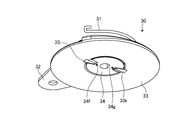
- the pressing member 30 includes an urging portion 31, a first rotating member 32, a second rotating member 33, and a fixing member 34. It is configured to be stacked in order.
- the first rotating member 32 and the second rotating member 33 are integrally rotated to have a predetermined rotation. Rotate in direction R1.
- the first rotation member 32 and the second rotation member 33 rotate in the predetermined rotation direction R1
- the first taper portions 33b and 33c provided in the second rotation member 33 are changed to the first rotation members 33b and 33c.
- the recess 40a (see FIG. 10) of the turning member 40 (see FIG. 10) that engages with the first taper portions 33b and 33c is pushed in, and the turning member 40 is rotated toward the connecting member 4c (see FIG. 6). Move.
- the fixed member 34 is fixed and attached so as not to move to the casing of the transmission device 4b (see FIG. 6), and rotatably supports the second rotating member 33. Further, as shown in FIG. 11E, the fixing member 34 has second tapered portions 34b and 34c.
- the second rotation member 33 rotates in the predetermined rotation direction R1
- the second taper portions 34b and 34c are convex portions 33j of the second rotation member 33 that face the second taper portions 34b and 34c.
- 33k (see FIG. 9) is pushed in the direction of the rotation axis, and the entire second rotation member 33 is moved in the direction of the rotation axis (upward in FIG. 8).
- the pressing member 30 can further rotate the rotating member 40 that contacts the second rotating member 33 toward the connecting member 4c.
- the pressing member 30 causes the first taper portions 33b and 33c and the second taper portions 34b and 34c to move the rotating member 40 toward the connecting member 4c. It can be rotated.
- action at the time of rotating the rotation member 40 to the side which goes to the connection member 4c with the press member 30 is mentioned later.
- the urging unit 31 is locked to the first rotating member 32, and urges the first rotating member 32 in the rotation direction R2 opposite to the predetermined rotation direction R1. Then, after an external force is applied in the predetermined direction F and the external force is released after the first rotating member 32 and the second rotating member 33 have made approximately 1 ⁇ 4 rotation in the predetermined rotating direction R1, The rotating member 32 is rotated in the rotation direction R2 by the urging unit 31, and the external force applying unit 32h returns to a predetermined position.
- the second rotating member 33 is not urged in the rotation direction R2 by the urging portion 31, the position when the external force is applied is maintained even after the external force is released. The Therefore, even after the external force is released, the pressing member 30 can maintain the state in which the rotating member 40 is rotated to the side toward the connecting member 4c.
- the urging unit 31 urges the first rotating member 32 and the second rotating member 33 to the fixed member 34. In other words, the urging unit 31 urges the first rotating member 32 and the second rotating member 33 in the rotation axis direction (downward in FIG. 8).
- FIG. 10 is a perspective view of the rotating member 40.
- the rotating member 40 is formed with a recess 40 a corresponding to the first tapered portions 33 b and 33 c (see FIG. 8) provided on the second rotating member 33 of the pressing member 30.
- the recess 40a engages with the first taper portions 33b and 33c so that the first taper portions 33b and 33c can rotate.
- the rotation member 40 is formed with a notch 40b to prevent the first taper portions 33b and 33c from pushing the rotation member 40 at a place other than the recess 40a when the pressing member 30 is rotated. Yes.
- the rotation member 40 is provided with two insertion portions 40c through which the shaft 51 (see FIG. 12) is inserted. Then, as shown in FIG. 12, the shaft 51 is inserted into the two insertion portions 40 c and the holes of the holding member 50 in a state where the portion where the hole of the holding member 50 is formed is sandwiched by the two insertion portions 40 c. . Thereby, the rotating member 40 is held by the holding member 50 so as to be rotatable around the shaft 51.
- FIG. 11A is a plan perspective view of the urging portion 31.
- the urging portion 31 includes a spring-shaped spring portion 31a and locking portions 31b and 31c provided at both ends of the spring portion 31a.
- the spring portion 31a has a function of urging the first rotating member 32 and the second rotating member 33 in a predetermined direction as described above.
- One locking portion 31b is locked to the engaging portion 32f (see FIG. 11B) of the first rotating member 32.
- the other locking portion 31c is locked at a predetermined location of the transmission device 4b (see FIG. 1).
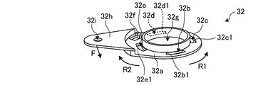
- FIG. 11B is a plan perspective view of the first rotating member 32.
- the first rotating member 32 has a disc-shaped main body portion 32a, and holes 32b, 32c, 32d, and 32e are formed at equal intervals in the circumferential direction of the main body portion 32a. Further, the main body portion 32a is provided with an engaging portion 32f between the hole portion 32d and the hole portion 32e, and a through portion 32g that is a circular hole is formed at the center portion.
- the engaging part 32f is provided between the hole part 32d and the hole part 32e, the position provided is not ask
- the first rotating member 32 is provided with an external force applying part 32h so as to protrude from the vicinity of the hole 32e to the outer peripheral side, and the external force applying part 32h is formed with a hole 32i.
- a wire (not shown) is locked in the hole 32i, and the user can apply an external force in a predetermined direction F to the pressing member 30 by pulling the wire.
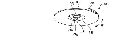
- FIG. 11C is a plan perspective view of the second rotating member 33.
- the second rotating member 33 has a disc-shaped main body portion 33a. And the 1st taper part 33b, 33c, wall part 33d, 33e, and the axial support part 33f are provided in the upper surface side of this main-body part 33a, and the penetration part 33g is formed.
- 1st taper part 33b, 33c is provided in the outer peripheral part of the main-body part 33a at equal intervals in the circumferential direction.
- the first taper portions 33b and 33c are provided over a quarter of each circumference along the circumferential direction, and the height gradually increases as the second rotation member 33 rotates in the rotation direction R1. It is configured. Further, the first taper portions 33b and 33c are arranged so as to have positions and shapes that are point-symmetric with respect to the rotation axis.
- the wall portions 33d and 33e are provided at equal intervals in the circumferential direction on the inner peripheral side of the main body portion 33a with respect to the first taper portions 33b and 33c, and are erected so as to face the rotation direction R1. Yes.
- the wall portions 33d and 33e are arranged so as to have positions and shapes that are point-symmetric with respect to the rotation axis.
- the cylindrical shaft support portion 33f is inserted through the through portion 32g (see FIG. 11B) of the first rotation member 32 (see FIG. 11B) and has a function of supporting the first rotation member 32 in a pivotal manner.
- the penetrating portion 33g is a circular hole penetrating from the upper surface to the lower surface of the main body portion 33a, and a shaft support portion 34h (see FIG. 11E) of a fixing member 34 (see FIG. 11E) described later is inserted.
- the second rotating member 33 is pivotally supported by the fixed member 34 so as to be rotatable. In the embodiment, the first rotating member 32 and the second rotating member 33 are supported on the same axis.
- FIG. 11D is a bottom perspective view of the second rotating member 33.
- groove portions 33h and 33i are formed on the lower surface side of the main body portion 33a, and convex portions 33j and 33k are provided.
- the groove portions 33h and 33i are formed at equal intervals in the circumferential direction inside the shaft support portion 33f (see FIG. 11C).
- the groove portions 33h and 33i are respectively formed over about 1 ⁇ 2 circumference along the circumferential direction, and correspond to second tapered portions 34b and 34c (see FIG. 11E) of the fixing member 34 (see FIG. 11E) described later.
- the groove portions 33h and 33i are arranged so as to have positions and shapes that are point-symmetric with respect to the rotation axis.
- the convex portions 33j and 33k are provided at equal intervals in the circumferential direction between the groove portion 33h and the groove portion 33i.
- the convex portions 33j and 33k are provided so as to be engageable with concave portions 34d and 34e (see FIG. 11E) of the fixing member 34 described later. Further, the convex portions 33j and 33k are arranged so as to have a point-symmetric position and shape with respect to the rotation axis.
- FIG. 11E is a plan perspective view of the fixing member 34.
- the fixing member 34 has grooves 33h and 33i (see FIG. 11D) and a through-hole 33g (see FIG. 11D) on the bottom surface side of the second rotating member 33 (see FIG. 11D) in a predetermined orientation. 11D).
- the fixing member 34 has a disk-shaped main body 34a. And the 2nd taper part 34b, 34c is provided in the circumferential direction at equal intervals on the outer periphery of this main-body part 34a.
- the second taper portions 34b and 34c are provided over about a quarter of the circumference along the circumferential direction, and are configured to gradually increase in height as the rotation proceeds in the rotation direction R1.
- the second taper portions 34b and 34c are arranged so as to have positions and shapes that are point-symmetric with respect to the rotation axis.
- concave portions 34d and 34e are formed at equal intervals in the circumferential direction.
- the recesses 34d and 34e are arranged so as to have positions and shapes that are point-symmetric with respect to the rotation axis.
- notches 34f and 34g are formed at equal intervals in the circumferential direction adjacent to the lowest portion of the second tapered portions 34b and 34c.
- the notches 34f and 34g have shapes corresponding to the convex portions 33j and 33k (see FIG. 11D) of the second rotating member 33.
- the notches 34f and 34g are arranged so as to have positions and shapes that are point-symmetric with respect to the rotation axis.
- a cylindrical shaft support portion 34h is provided at the center of the main body portion 34a, and is inserted through the through portion 33g of the second rotation member 33 to support the second rotation member 33. Further, the through portion 34i formed in the shaft support portion 34h has a function of fixing the fixing member 34 to the casing of the transmission device 4b (see FIG. 6) by inserting a fixing member (not shown) and holding the entire pressing member 30.
- the state before the operation is such that the highest portion of the first tapered portion 33 b of the first rotating member 32 with respect to the external force applying portion 32 h of the first rotating member 32 is It is in a state where it is at a position rotated about 1/4 in the rotation direction R1, and the highest portion of the first taper portion 33c is at a position rotated about 1/4 in the rotation direction R2.
- the convex portions 33 j and 33 k of the second rotating member 33 are in a state of being locked to the notches 34 f and 34 g of the fixing member 34, respectively.
- the side wall 32b1 of the hole part 32b presses the wall part 33d of the second rotating member 33
- the side wall 32d1 of the hole part 32d presses the wall part 33e of the second rotating member 33.
- the member 33 also rotates in the rotation direction R1.
- the rotating member 40 (see FIG. 6) arranged so as to face the upper surface of the second rotating member 33 is rotated in the rotation axis direction (upward in FIGS. 11A to 11E) by the first taper portion 33b. Pushed in.
- the convex portions 33j and 33k on the bottom surface side of the second rotating member 33 are respectively caused by the second tapered portions 34b and 34c of the fixing member 34 facing each other. Pushed in the direction of the rotation axis.
- the convex portions 33j and 33k of the second rotating member 33 slide on the inclined surfaces of the second tapered portions 34b and 34c of the fixing member 34.
- the second rotating member 33 moves in a direction away from the fixed member 34 by moving upward.
- the entire second rotation member 33 moves in the direction of the rotation axis (upward in FIGS. 11A to 11E), so that the second rotation member 33 pushes the rotation member 40 further in the direction of the rotation axis. be able to. That is, by using the second tapered portions 34b and 34c having a compact shape, the pressing member 30 can sufficiently push the rotating member 40 in the rotation axis direction even in a space-saving manner.
- the first rotating member 32 is rotated approximately 1 ⁇ 4 in the rotational direction R2 by the urging unit 31, and the external force applying unit 32h is moved to the predetermined position.
- the walls 33d and 33e of the second rotating member 33 are tapered as shown in FIG. 11C, and when the first rotating member 32 rotates in the rotation direction R2, the walls 33d and 33e are This is because none of the side walls 32b1, 32c1, 32d1, and 32e1 of the first rotating member 32 is pressed.
- the second rotating member 33 is not biased in the rotation direction R2, and the convex portions 33j and 33k are engaged with the concave portions 34d and 34e. Without holding the position before releasing the external force.
- the rotating member 40 comes into contact with the portion with the highest height of the first taper portion 33b, and the convex portions 33j and 33k become the portions with the highest height of the second taper portions 34b and 34c. They are located in the adjacent recesses 34d and 34e, respectively. That is, the protrusions 33j and 33k are engaged with the recesses 34d and 34e, so that the pressing member 30 keeps the rotating member 40 pushed to the maximum in the direction of the rotation axis even after the external force is released. Can do.
- the second rotating member 33 rotates about 1 ⁇ 4 in the rotation direction R ⁇ b> 1, and the convex portions 33 j and 33 k are fixed to the fixing member 34. Locked by the recesses 34d and 34e, the first rotating member 32 rotates about 1 ⁇ 4 in the rotational direction R1, then rotates about 1 ⁇ 4 in the rotational direction R2, and the external force application unit 32h returns to a predetermined position. In the state, the operation of each member of the pressing member 30 when an external force is applied again in the predetermined direction F will be described.
- the side wall 32c1 of the hole portion 32c presses the wall portion 33d of the second rotating member 33
- the side wall 32e1 of the hole portion 32e presses the wall portion 33e of the second rotating member 33, thereby causing the second rotation.
- the member 33 also rotates in the rotation direction R1.
- the rotating member 40 disposed so as to face the upper surface of the second rotating member 33 is released from the first tapered portion 33b, and the state of being pushed by the first tapered portion 33b is released.
- the convex portions 33j and 33k on the bottom surface side of the second rotating member 33 are disengaged from the concave portions 34d and 34e of the fixing member 34, so that the notches having a low height are formed. It rotates to the parts 34g and 34f, respectively. In other words, the state in which the second rotating member 33 is pushed by the second tapered portions 34b and 34c is also released.
- the second rotating member 33 since the second rotating member 33 is biased to the fixing member 34 by the biasing portion 31, the convex portions 33j and 33k engage with the notches 34g and 34f, respectively, and the second rotating member 33 is engaged. Keeps the low position.
- the rotating member 40 is pushed from the state pushed to the maximum in the rotation axis direction. It returns to the state where it is not pushed in.
- the holes 32b to 32e, the concave portions 34d and 34e, and the notches 34f and 34g are formed at equal intervals in the circumferential direction, respectively.
- Tapered portions 33b and 33c, wall portions 33d and 33e, convex portions 33j and 33k, and second tapered portions 34b and 34c are provided at equal intervals in the circumferential direction. Therefore, by repeatedly applying and releasing the external force in the predetermined direction F, the pressing member 30 alternately switches between the state in which the rotating member 40 is pushed in the rotation axis direction to the maximum and the state in which it is not pushed in. Can do.
- FIG. 12 is a diagram illustrating an example of the positional relationship between the gear 10 b and the gear 20.
- FIG. 12 shows the relationship between the gear 10b and the gear 20 when the rotation member 40 is not pushed in the rotation axis direction and the rotation member 40 is not rotated to the side toward the connecting member 4c (see FIG. 6). It is a figure which shows a positional relationship.
- the gear 10b and the gear 20 are engaged and connected. That is, when the rotation member 40 is not rotating, the connection state is the first state in which the gear 20 and the gear 10b are connected.
- first position the positional relationship between the first connecting member 6a and the second connecting member 6b is such that the first connecting member 6a and the second connecting member 6b are farthest apart (hereinafter referred to as “first position”).
- first position the connection state between the gear 20 and the gear 10b is the first state.
- the length in the rotation axis direction of the connecting member 4c including the first connecting member 6a and the second connecting member 6b is maximized. That is, when the length of the connecting member 4c in the rotation axis direction is the maximum length (hereinafter referred to as “first length”), the connection state between the gear 20 and the gear 10b is the first. 1 state.
- FIG. 13 is a diagram for explaining a method of switching from the first state in which the gear 20 and the gear 10 b are connected to the second state in which the gear 20 and the gear 10 b are not connected by using the switching unit 25. .
- FIG. 13 the positional relationship among the pressing member 30, the rotating member 40, the holding member 50, the shaft 5a, the gear 10b, and the gear 20 is shown.
- a user who switches the shutter device 1 from electric to manual and then opens and closes the shutter 2 applies an external force in a predetermined direction F shown in FIG. Rotate to R1.
- the rotating member 40 is pushed to the maximum in the rotation axis direction by the first tapered portions 33b and 33c (see FIG. 11C) and the second tapered portions 34b and 34c (see FIG. 11E). Then, it rotates in the rotation direction R3 on the side toward the connecting member 4c (see FIG. 6). And by rotation of this rotation member 40, the rotation member 40 presses the 2nd connection member 6b provided with the gear 10b to a rotating shaft direction (upward direction in FIG. 13), and a 1st connection member. 6a (see FIG. 3) is moved. That is, by rotating the pressing member 30 in the rotation direction R1, the second connecting member 6b moves to the first connecting member 6a side.
- the predetermined distance refers to both end portions in the rotation axis direction of the gear 20 from the end portion 5g on the switching unit 25 side among the both end portions in the rotation axis direction of the gear 10b. Is the distance in the direction of the rotation axis to the end 20a opposite to the switching unit 25 side, and is hereinafter referred to as “releasable distance”.
- first connecting member 6a and the second connecting member 6b are in a state in which the positional relationship between the first connecting member 6a and the second connecting member 6b is more than the disengageable distance in the rotation axis direction from the first positional relationship.
- second positional relationship the positional relationship with the connecting member 6b is changed (hereinafter referred to as “second positional relationship”), the connected state between the gear 20 and the gear 10b is the second state. This second positional relationship is different from the first positional relationship.
- the rotation shaft of the connecting member 4c including the first connecting member 6a and the second connecting member 6b is a length (hereinafter referred to as “second length”) that is shorter than the first length by at least the releasable distance. That is, when the length of the connecting member 4c in the rotation axis direction is the second length different from the first length, the connected state of the gear 20 and the gear 10b is the second state.
- a connection state be a 2nd state.
- the rotating member 40 can be kept in a state where it is pushed to the maximum in the direction of the rotation axis, so that the user can easily maintain the second state, The shutter 2 can be manually opened and closed.
- the rotating member 40 has a contact portion 40d (see FIG. 10) that contacts the gear 10b of the second connecting member 6b on the surface opposite to the concave portion 40a (see FIG. 10) that contacts the pressing member 30. ) Is provided. And since the contact part 40d has R shape, even when the rotation member 40 rotates to the rotation direction R3 and pushes in the gear 10b, it can prevent damaging the gear 10b.
- the driving device 4 can release and set the mechanical lock by the motor 4a without using expensive parts such as a clutch mechanism.
- the mechanical lock can be released and set by the motor 4a while the cost is suppressed. Therefore, the drive device 4 can switch the shutter device 1 to manual or electric while suppressing cost.
- the drive device 4 can release or set the mechanical lock using the switching unit 25 having a simple configuration. Therefore, in the drive device 4, the shutter device 1 can be switched to manual or electric with a simple configuration.
- the shutter device 4 can be easily switched from manual to electric. That is, since an electric shutter device can be easily configured using an existing manual shutter device, the cost can be reduced.
- a manual shutter device an example of a method of converting a shutter device having a shaft, a drum, and a roll (corresponding to the rotation mechanism 5 according to the embodiment) into an electric shutter device will be described.
- both ends of the shaft 5a of the manual shutter device are attached to the wall of the house, the user first removes the shaft 5a from the wall. Next, the user attaches the first connecting member 6a to the drum 5b so as to be rotatable around the shaft 5a.
- the user brings one end of the spring 6c into contact with the contact surface 7e of the first connecting member 6a, and makes the other end of the spring 6c contact with the contact surface 10e of the second connecting member 6b. Then, the second connecting member 6b is attached to the first connecting member 6a.
- the user needs to engage the shaft fixing screw 61 with the hole of the shaft guide 60 and the through hole formed in the shaft 5a.
- the second connecting member 6b does not move to the first connecting member 6a side, the user can pass through the hole of the shaft guide 60 and the shaft 5a formed by the second connecting member 6b. The hole cannot be visually observed.
- the second connecting member 6b is movable toward the first connecting member 6a.
- FIG. 14 is a diagram showing a state before the second connecting member 6b according to the embodiment moves to the first connecting member 6a side (that is, the first state).
- FIG. 15 is a diagram illustrating a state after the second connecting member 6b according to the embodiment has moved to the first connecting member 6a side (that is, the second state). That is, the second connecting member 6b is movable to the first connecting member 6a side so that the connected state is changed from the first state shown in FIG. 14 to the second state shown in FIG.
- the user moves the second connecting member 6b to the first connecting member 6a side to a position where the hole of the shaft guide 60 and the through hole formed in the shaft 5a can be confirmed.
- the shaft 5a can be fixed using the screw 61 after being moved. Therefore, according to the drive device 4 according to the embodiment, the shutter device can be easily changed from manual to electric.
- the drive device 4 includes a motor 4a, a transmission device 4b, a connecting member 4c (first connecting member 6a, second connecting member 6b, spring 6c), and a switching unit 25 (pressing member 30).
- the rotation member 40) is provided outside the rotation mechanism 5.
- the drive device 4 includes a motor 4a, a transmission device 4b, a connecting member 4c (first connecting member 6a, second connecting member 6b, spring 6c), and a switching unit 25 (pressing member 30, rotating member). 40) is provided outside the shaft 5a.
- the drive device 4 of the embodiment includes a motor 4a, a transmission device 4b, a connecting member 4c (first connecting member 6a, second connecting member 6b, spring 6c), and a switching unit 25 (pressing member 30, Since the rotating member 40) is provided outside the shaft 5a, if any component fails, only the failed component needs to be replaced. Therefore, the drive device 4 of the embodiment can reduce the cost of repair when a failure occurs in a part of the component.
- the shutter device has been described as an example including the driving device and the driven portion, but the present invention is not limited to this.
- the present invention may be applied to a winding device such as a screen, a banner, or a partition cloth.
- the drive device 4 includes the drive unit (motor 4a), the gear group (gears 15 to 20), the connecting member 4c, and the switching unit 25.
- the driving unit (motor 4a) generates a driving force for rotating the driven unit (rotating mechanism 5), and is provided outside the driven unit (rotating mechanism 5).
- the gear group (gears 15 to 20) transmits the driving force generated by the driving unit (motor 4a) to the driven unit (rotating mechanism 5).
- the connecting member 4c is provided between the gear group (gears 15 to 20) and the driven part (rotating mechanism 5), and is connected to a predetermined gear 20 among a plurality of gears included in the gear group (gears 15 to 20). Link.
- the switching unit 25 can switch the connection state between the predetermined gear 20 and the connecting member 4c by an external force applied in a direction (predetermined direction F) orthogonal to the rotation axis of the driven unit (rotating mechanism 5). As a result, it is possible to provide the drive device 4 that can release and set the mechanical lock by the drive unit (motor 4a) while suppressing the cost.
- the switching unit 25 includes a first rotating member 32 that rotates in a predetermined rotation direction R1 by application of an external force, and a surface that faces the connecting member 4c, and performs the first rotation.
- a second rotation member 33 that rotates in the predetermined rotation direction R1 as the member 32 rotates in the predetermined rotation direction R1, a fixing member 34 that rotatably supports the second rotation member 33, and a second Between the rotating member 33 and the connecting member 4c.
- the rotating member 40 is rotatably arranged.
- the second rotating member 33 rotates with the rotation in the predetermined rotation direction R1.
- the state where and are connected is released. Thereby, it is possible to switch the shutter device 1 to manual or electric with a simple configuration.
- the second rotating member 33 includes first tapered portions 33b and 33c on the surface facing the connecting member 4c, and the second rotating member 33 is rotated in the predetermined rotation direction R1.
- 1 taper part 33b, 33c rotates the rotation member 40 to the rotation direction R3 which goes to the connection member 4c, and cancels
- the fixing member 34 includes second tapered portions 34b and 34c on the surface facing the second rotating member 33, and the first member 34 rotates in the predetermined rotation direction R1.
- the second tapered portions 34b and 34c move the second rotating member 33 in the direction toward the rotating member 40, thereby releasing the state where the predetermined gear 20 and the connecting member 4c are connected.
- the rotation member 40 can be sufficiently pushed in the direction of the rotation axis even in a space-saving manner.
- the fixing member 34 has first engaging portions (recesses 34d and 34e) on the surface facing the second rotating member 33, and the second rotating member 33 is
- the second engaging portion (convex portion 33j, 33k) corresponding to the first engaging portion (concave portion 34d, 34e) has a second engaging portion (convex portion) that rotates in a predetermined rotation direction R1.
- 33j and 33k) are locked to the first engaging portions (recess portions 34d and 34e), thereby maintaining a state where the predetermined gear 20 and the connecting member 4c are not connected. Thereby, the user can manually open and close the shutter 2 while maintaining the second state easily.
- the switching unit 25 urges the first rotating member 32 in the rotation direction R2 opposite to the predetermined rotation direction R1, and the first rotating member 32 and the second rotating member 32. And the urging portion 31 for urging the rotating member 33 to the fixing member 34.
- the first rotating member 32 is pivotally supported by the second rotating member 33, and the application of external force is released.
- the urging unit 31 rotates in the rotation direction R2 opposite to the predetermined rotation direction R1.
Landscapes
- Engineering & Computer Science (AREA)
- Structural Engineering (AREA)
- Architecture (AREA)
- Civil Engineering (AREA)
- Operating, Guiding And Securing Of Roll- Type Closing Members (AREA)
- Transmission Devices (AREA)
Abstract
実施形態に係る駆動装置(4)は、被駆動部を回転駆動させる駆動力を発生し、被駆動部の外部に設けられる駆動部と、駆動部により発生された駆動力を被駆動部に伝達するギヤ群と、ギヤ群と被駆動部との間に設けられ、ギヤ群に含まれる複数のギヤ(15~20)のうち所定のギヤ(20)と連結する連結部材(4c)と、被駆動部の回転軸と直交する方向に印加される外力により所定のギヤ(20)と連結部材(4c)との連結状態を切替可能な切替部(25)と、を備える。
Description
本発明は、駆動装置に関する。
従来、クラッチ機構を用いて、モータなどの駆動部による機械的なロックを解除することで、手動でシャッターを開閉可能な状態にするとともに、かかるクラッチ機構を用いて、機械的なロックを設定することで、電動でシャッターを開閉可能とする駆動装置がある。
しかしながら、従来の駆動装置では、機械的なロックの解除および設定を行うクラッチ機構のコストが高いという問題がある。
本発明は、上記に鑑みてなされたものであって、コストを抑制しつつ、駆動部による機械的なロックの解除および設定を行うことができる駆動装置を提供することを目的とする。
上述した課題を解決し、目的を達成するために、本発明の一態様に係る駆動装置は、被駆動部を回転駆動させる駆動力を発生し、前記被駆動部の外部に設けられる駆動部と、前記駆動部により発生された前記駆動力を前記被駆動部に伝達するギヤ群と、前記ギヤ群と前記被駆動部との間に設けられ、前記ギヤ群に含まれる複数のギヤのうち所定のギヤと連結する連結部材と、前記被駆動部の回転軸と直交する方向に印加される外力により前記所定のギヤと前記連結部材との連結状態を切替可能な切替部と、を備える。
本発明の一態様によれば、コストを抑制しつつ、駆動部による機械的なロックの解除および設定を行うことができる。
以下、実施形態に係る駆動装置について図面を参照して説明する。なお、図面における各要素の寸法の関係、各要素の比率などは、現実と異なる場合がある。また、図面の相互間においても、互いの寸法の関係や比率が異なる部分が含まれている場合がある。
<シャッター装置の構成>
図1は、実施形態に係る駆動装置を有するシャッター装置全体の構成を示す模式図である。図1に示すように、実施形態に係るシャッター装置1は、シャッター2と、取付部材3と、駆動装置4と、回転機構5とを備える。
図1は、実施形態に係る駆動装置を有するシャッター装置全体の構成を示す模式図である。図1に示すように、実施形態に係るシャッター装置1は、シャッター2と、取付部材3と、駆動装置4と、回転機構5とを備える。
シャッター2は、複数のスラッド2aを含んで構成されている。取付部材3は、家屋の壁などにシャッター装置1を取り付けるための部材である。例えば、取付部材3の所定の面を壁に押し当てた状態で、ねじなどの固定手段で取付部材3を壁に固定させることで、シャッター装置1が壁に取り付けられる。
駆動装置4は、回転機構5を回転させる駆動力を発生し、発生された駆動力を回転機構5に伝達することで、回転機構5を回転駆動させる。駆動装置4は、モータ4aと、伝達装置4bと、連結部材4c(図2参照)と、切替部25(図6参照)を備える。
モータ4aは、図示しない電源からの電力の供給を受けて、モータ4aの出力軸を正逆回転することにより、回転機構5を正逆回転させる駆動力を発生する。実施形態に係るモータ4aは、回転機構5の外側に設けられており、いわゆる外付けのモータである。モータ4aは、駆動部の一例である。
伝達装置4bは、モータ4aにより発生された駆動力を連結部材4cに伝達する。また、切替部25は、伝達装置4bと連結部材4cとの連結状態を切り替えることができる。伝達装置4b、連結部材4cおよび切替部25の詳細については後述する。
回転機構5は、駆動装置4による駆動の対象となる装置であり、被駆動部の一例である。実施形態では、回転機構5に、シャッター2の一端が固定されている。そして、駆動装置4により回転機構5が正逆回転されることで、回転機構5によりシャッター2が巻き上げられたり、巻き戻されたりして、シャッター2の開閉が行われる。
図2は、連結部材4cおよび回転機構5の斜視図であり、図3は、連結部材4cおよび回転機構5の正面図である。連結部材4cは、伝達装置4b(図1参照)と回転機構5とを連結する部材であり、伝達装置4bからの駆動力を回転機構5に伝達する。図2および図3に示すように、連結部材4cは、第1の連結部材6aと、第2の連結部材6bと、ばね6cとを有する。連結部材4cの各部材の詳細については後述する。
回転機構5は、シャフト5aと、ドラム5bと、ロール5cとを有する。シャフト5aは、後述するシャフトガイド60(図6参照)に固定される。したがって、シャフト5a自体は回転しない。
ドラム5bは、シャフト5aを回転軸として、シャフト5a周りを回転可能に設けられる。ドラム5bは、例えば、シャフト5aの両側部分に2つ設けられる。ロール5cは、両端がそれぞれシャフト5aの両側部分に設けられるドラム5bに固定され、ドラム5bと一体的に回転する。ロール5cは、例えば、ドラム5bの周方向に等間隔に2つ設けられる。
そして、ロール5cには、シャッター2の一端が固定される。これにより、ドラム5bおよびロール5cの回転に伴って、シャッター2が開閉する。なお、ドラム5bおよびロール5cの数は上記の数に限定されない。ロール5cに取り付けられるシャッター2が開閉可能であれば、ドラム5bおよびロール5cの数は問わない。
図4は、連結部材4cの部材の1つである第1の連結部材6aの斜視図である。図4に示すように、第1の連結部材6aは、筒状部材であり、孔7aが形成されている。孔7aには、シャフト5a(図2参照)が挿通される。第1の連結部材6aは、シャフト5aを回転軸として、シャフト5a周りを回転可能に設けられる。
また、第1の連結部材6aは、外径が異なる2つの部材9a、9bが一体成形されたものである。2つの部材9a、9bのうち、外径が大きい方の部材9bは、複数の突起部7bを有する。そして、かかる複数の突起部7bが、ドラム5b(図2参照)に形成された複数の凹部と係合することで、ドラム5bに対して第1の連結部材6aが取り付けられる。
これにより、第1の連結部材6aがシャフト5a周りを回転する場合には、第1の連結部材6aの回転に伴ってドラム5bも回転する。なお、係合するための形式としては、ドラム5bに形成された複数の孔に、複数の突起部7bが係合されるものでもよい。ドラム5bに対し、第1の連結部材6aが回転規制された状態で固定されれば、係合の形式は問わない。
また、2つの部材9a、9bのうち、外径が小さい方の部材9aの周面には、複数の溝7cおよび複数の溝7dが形成されている。実施形態では、溝7c、7dがそれぞれ3つずつ、周方向に交互となるように等間隔で形成されている。溝7cは、第1の連結部材6aの周面の回転軸方向における中央部分8bから、第1の連結部材6aの一端8cまでにわたって形成されている。
また、溝7dは、上述の中央部分8bから、第1の連結部材6aの一端8cよりも内側の部分8aまでにわたって形成されている。なお、溝7c、7dは、それぞれ複数形成されていればよく、例えば2つずつでも、4つずつでもよい。
また、部材9aを覆うように、ばね6c(図2参照)が設けられる。そして、かかるばね6cの一端は、部材9bに設けられる当接面7eに当接する。
図5は、連結部材4cの部材の1つである第2の連結部材6bの斜視図である。図5に示すように、第2の連結部材6bは、筒状部材であり、孔10aが形成されている。孔10aには、シャフト5a(図2参照)が挿通される。第2の連結部材6bは、シャフト5aを回転軸として、シャフト5a周りを回転可能に設けられる。
また、第2の連結部材6bは、筒の一端部にギヤ10bを有する。かかるギヤ10bは、伝達装置4b(図1参照)が有する複数のギヤ(ギヤ群)のうち、最終ギヤであるギヤ20(図6参照)と噛み合う。これにより、モータ4a(図1参照)により発生された駆動力は、伝達装置4bの複数のギヤを経由して、第2の連結部材6bのギヤ10bに伝達される。
また、第2の連結部材6bには、第1の連結部材6a(図4参照)の部材9a(図4参照)に形成された溝7dに対応して、周方向に等間隔に複数のねじ孔10cが形成されている。実施形態では、3つのねじ孔10cが周方向に等間隔に形成されている。
さらに、第2の連結部材6bの内周面には、第1の連結部材6aの部材9aに形成された溝7cに対応して、周方向に等間隔に突起部10dが設けられている。実施形態では、3つの突起部10dが周方向に等間隔に設けられている。
なお、ねじ孔10cおよび突起部10dは、それぞれ溝7dおよび溝7cに対応して形成されるため、溝7dおよび溝7cが2つずつの場合は、ねじ孔10cおよび突起部10dも2つずつ、溝7dおよび溝7cが4つずつの場合は、ねじ孔10cおよび突起部10dも4つずつ形成されるということは言うまでもない。
ここで、第2の連結部材6bの内径は、図4に示した第1の連結部材6aの部材9aの外径よりも大きい。これにより、部材9aの一部が第2の連結部材6bの孔10aに挿入された状態で、ねじ孔10cを挿通したねじ10f(図3参照)の先端部分が、溝7d内を移動可能に、溝7dと係合する。また、突起部10dが、溝7c内を移動可能に、溝7cと係合する。したがって、第2の連結部材6bがシャフト5a周りを回転する場合には、第2の連結部材6bの回転に伴って第1の連結部材6aも回転する。
また、第2の連結部材6bは、第1の連結部材6aに対して回転軸方向に移動(摺動)可能な状態で、第1の連結部材6aに支持される。すなわち、第2の連結部材6bは、第1の連結部材6aに対して回転軸方向に移動可能である。そして、第2の連結部材6bが第1の連結部材6aに対して回転軸方向に移動可能であるため、連結部材4cは、回転軸方向に伸縮可能となる。
ただし、実施形態では、第1の連結部材6aに対して第2の連結部材6bが移動可能な範囲は制限されている。例えば、第2の連結部材6bは、ねじ孔10cを挿通したねじ10fの先端部分が、溝7dの部分8a(図4参照)から、中央部分8b(図4参照)までを移動する範囲内で、第1の連結部材6aに対して移動可能となる。
続いて、図2~5を参照して、連結部材4cの部材の1つであるばね6cについて説明する。ばね6cは、第1の連結部材6aの部材9aの一部が第2の連結部材6bの孔10aに挿入された状態で、第2の連結部材6bの一部および部材9aを覆うように設けられる。
ばね6cの一端は、第1の連結部材6aの当接面7eに当接し、ばね6cの他端は、第2の連結部材6bの当接面10e(図5参照)に当接する。ばね6cは、第1の連結部材6aと第2の連結部材6bとがそれぞれ離れる方向に、当接面7eおよび当接面10eに対して付勢する。
これにより、第2の連結部材6bに対して、ばね6cの付勢力以外の力が加わっていない場合には、第2の連結部材6bのねじ孔10cを挿通したねじ10fの先端部分が、溝7dの部分8aに位置する状態となる。換言すると、第2の連結部材6bに対して、ばね6cの付勢力以外の力が加わっていない場合には、第1の連結部材6aと第2の連結部材6bとが最も離れる状態となる。
<伝達装置の構成>
次に、図6および図7を参照して、伝達装置4bの構成について説明する。図6は、実施形態に係る伝達装置4bの正面図であり、図7は、実施形態に係る伝達装置4bの背面図である。なお、図6および図7では、伝達装置4bの筐体(ケース)の図示は省略している。
次に、図6および図7を参照して、伝達装置4bの構成について説明する。図6は、実施形態に係る伝達装置4bの正面図であり、図7は、実施形態に係る伝達装置4bの背面図である。なお、図6および図7では、伝達装置4bの筐体(ケース)の図示は省略している。
伝達装置4bは、ギヤ群を有し、モータ4aにより発生された駆動力を連結部材4cに伝達する。図6および図7に示すように、伝達装置4bは、ギヤ15~20と、シャフトガイド60とを有する。また、連結部材4cに隣接して、押圧部材30および回動部材40を有する切替部25と、回動部材40を保持する保持部材50とが取り付けられている。
ギヤ15~20の各種のギヤについて、モータ4a側から説明する。図7に示したギヤ15は、モータ4aの出力軸に取り付けられている。そのため、出力軸の回転に伴って、ギヤ15は回転する。したがって、モータ4aにより発生された駆動力は、ギヤ15に伝達される。
ギヤ16~19は、それぞれ同一回転軸周りを回転する2つのギヤを有する。ギヤ15と、ギヤ16が有する2つのギヤのうち、一方のギヤとが噛み合っている。また、ギヤ16の他方のギヤは、ギヤ17が有する2つのギヤのうち、一方のギヤと噛み合っている。また、ギヤ17の他方のギヤは、ギヤ18が有する2つのギヤのうち、一方のギヤと噛み合っている。
また、ギヤ18の他方のギヤは、ギヤ19が有する2つのギヤのうち、一方のギヤと噛み合っている。また、ギヤ19の他方のギヤは、最終ギヤであるギヤ20と噛み合っている。そして、ギヤ20は、連結部材4cの第2の連結部材6b(図5参照)に設けられるギヤ10bとも噛み合っている。
すなわち、ギヤ15~20がすべて連結されていることから、伝達装置4bは、モータ4aにより発生された駆動力を連結部材4c(ギヤ10b)に伝達することができる。なお、ギヤ群に含まれるギヤの数は、上記の6つに限定されない。モータ4aにより発生された駆動力を連結部材4cに伝達することができれば、ギヤ15とギヤ10bの中間に位置するギヤの数は問わない。
ここで、上述のように、連結部材4cは駆動力を回転機構5(図2参照)に伝達する。したがって、モータ4aにより発生された駆動力は、伝達装置4bおよび連結部材4cを経由して、回転機構5に伝達される。
シャフトガイド60は、コの字型の3面の部材であり、端部が更に3面が外側に折り曲げられた部材である。シャフトガイド60には、シャフト5a(図2参照)を固定するための孔(図示せず)が形成されている。
そして、かかるシャフトガイド60の孔と、シャフト5aに形成された貫通孔(図示せず)と、保持部材50(図7参照)に形成された孔(図示せず)とを、シャフト固定用のねじ61で係合させることで、シャフト5aは、回転が規制された状態でシャフトガイド60に保持されるとともに、保持部材50は、シャフトガイド60に保持される。
また、シャフトガイド60は、ねじなどにより、伝達装置4bの筐体に取り付けられる。したがって、シャフト5aは、回転が規制された状態で伝達装置4bにより保持されるとともに、保持部材50も、伝達装置4bにより保持される。
切替部25は、押圧部材30と回動部材40とを有し、伝達装置4bが有するギヤ群の最終ギヤであるギヤ20と、連結部材4cのギヤ10bとの連結状態を切り替えることができる。かかる連結状態は、ギヤ20とギヤ10bとが連結する状態(以下、「第1の状態」と呼称する。)と、ギヤ20とギヤ10bとが連結しない状態(以下、「第2の状態」と呼称する。)とを有する。
押圧部材30は、所定の方向Fに外力が印加された場合に、隣接する回動部材40を連結部材4cに向かう側に回動させることにより、かかる連結状態を第1の状態から第2の状態、または第2の状態から第1の状態に切り替えることができる。なお、かかる所定の方向Fは、被駆動部である回転機構5の回転軸とは直交する方向である。押圧部材30の詳細については後述する。
回動部材40は、押圧部材30と、連結部材4cの第2の連結部材6bとの間に挟まれるように配置され、保持部材50(図7参照)に回動可能に保持されている。
<切替部の構成>
続いて、切替部25の具体的な構成について、図8~図11Eを用いて説明する。図8は、切替部25の部材の1つである押圧部材30の平面斜視図であり、図9は、押圧部材30の底面斜視図である。また、図10は、切替部25の部材の1つである回動部材40の斜視図である。さらに、図11A~図11Eは、押圧部材30の各構成部材を示す平面斜視図または底面斜視図である。以下では、まず切替部25の各部材の概要について図8~図10を中心に説明し、その後、切替部25、特に押圧部材30の詳細について図11A~図11Eを中心に説明する。
続いて、切替部25の具体的な構成について、図8~図11Eを用いて説明する。図8は、切替部25の部材の1つである押圧部材30の平面斜視図であり、図9は、押圧部材30の底面斜視図である。また、図10は、切替部25の部材の1つである回動部材40の斜視図である。さらに、図11A~図11Eは、押圧部材30の各構成部材を示す平面斜視図または底面斜視図である。以下では、まず切替部25の各部材の概要について図8~図10を中心に説明し、その後、切替部25、特に押圧部材30の詳細について図11A~図11Eを中心に説明する。
図8および図9に示すように、押圧部材30は、付勢部31と、第1の回転部材32と、第2の回転部材33と、固定部材34とを有し、かかる各部材が上から順に積み重ねられるように構成されている。そして、第1の回転部材32の外力印加部32hに対して所定の方向Fに外力が印加された場合、第1の回転部材32と第2の回転部材33とは、一体的に所定の回転方向R1に回転する。
ここで、第1の回転部材32と第2の回転部材33とが所定の回転方向R1に回転すると、第2の回転部材33に設けられている第1のテーパ部33b、33cが、かかる第1のテーパ部33b、33cと係合する回動部材40(図10参照)の凹部40a(図10参照)を押し込んで、回動部材40を連結部材4c(図6参照)に向かう側に回動させる。
固定部材34は、伝達装置4b(図6参照)の筐体に動かないように固定されて取り付けられ、第2の回転部材33を回転自在に軸支している。また、固定部材34は、図11Eに示すように、第2のテーパ部34b、34cを有する。
そして、第2の回転部材33が所定の回転方向R1に回転した場合、第2のテーパ部34b、34cは、かかる第2のテーパ部34b、34cと向かい合う第2の回転部材33の凸部33j、33k(図9参照)を回転軸方向に押し込んで、第2の回転部材33全体を回転軸方向(図8では上方向)に移動させる。これにより、押圧部材30は、第2の回転部材33と当接する回動部材40を連結部材4cに向かう側にさらに回動させることができる。
すなわち、押圧部材30は、所定の方向Fに外力が印加された場合、第1のテーパ部33b、33cおよび第2のテーパ部34b、34cにより、回動部材40を連結部材4cに向かう側に回動させることができる。なお、実施形態において、押圧部材30により回動部材40を連結部材4cに向かう側に回動させた場合の作用については後述する。
付勢部31は、第1の回転部材32に係止されており、第1の回転部材32を所定の回転方向R1とは反対の回転方向R2に付勢する。そして、所定の方向Fに外力が加わり、第1の回転部材32と第2の回転部材33とが所定の回転方向R1に約1/4回転した後に、かかる外力が解放されると、第1の回転部材32は付勢部31により回転方向R2に回転し、外力印加部32hは所定の位置に戻る。
一方で、第2の回転部材33は、付勢部31により回転方向R2には付勢されていないことから、かかる外力が解放された後も、かかる外力が印加された際の位置が維持される。したがって、外力が解放された後も、押圧部材30は、回動部材40を連結部材4cに向かう側に回動させた状態を維持することができる。
さらに、付勢部31は、第1の回転部材32と第2の回転部材33とを、固定部材34に付勢する。換言すると、付勢部31は、第1の回転部材32と第2の回転部材33とを、回転軸方向(図8では下方向)に付勢する。
図10は、回動部材40の斜視図である。図10に示すように、回動部材40には、押圧部材30の第2の回転部材33に設けられる第1のテーパ部33b、33c(図8参照)に対応して、凹部40aが形成される。この凹部40aは、第1のテーパ部33b、33cを回動可能に、第1のテーパ部33b、33cと係合する。また、回動部材40には切欠部40bが形成されており、押圧部材30の回動時に第1のテーパ部33b、33cが凹部40a以外の箇所で回動部材40を押し込むことを防止している。
さらに、回動部材40には、シャフト51(図12参照)が挿通される2つの挿通部40cが設けられている。そして、図12に示すように、2つの挿通部40cにより保持部材50の孔が形成された部分が挟まれた状態で、シャフト51が2つの挿通部40cおよび保持部材50の孔に挿通される。これにより、回動部材40は、保持部材50により、シャフト51周りを回動可能に保持されている。
続いて、押圧部材30の詳細について、図11A~図11Eを用いて説明する。図11Aは、付勢部31の平面斜視図である。付勢部31は、バネ形状のバネ部31aと、かかるバネ部31aの両端部に設けられる係止部31b、31cとを有する。
バネ部31aは、第1の回転部材32と第2の回転部材33とを、上述のように所定の方向に付勢する機能を有する。また、一方の係止部31bは、第1の回転部材32の係合部32f(図11B参照)に係止される。なお、他方の係止部31cは、伝達装置4b(図1参照)の所定の箇所に係止される。
図11Bは、第1の回転部材32の平面斜視図である。第1の回転部材32は、円板形状の本体部32aを有し、かかる本体部32aの周方向に等間隔に、孔部32b、32c、32d、32eが形成されている。また、本体部32aには、孔部32dと孔部32eの間に係合部32fが設けられ、中心部に円孔である貫通部32gが形成されている。
なお、係合部32fは、孔部32dと孔部32eの間に設けられているが、設けられる位置は問わない。つまり、例えば、孔部32cと孔部32dの間に設けられても良いし、孔部32eと周方向で等しい位置かつ径方向外側の位置に設けられても良い。
さらに、第1の回転部材32には、孔部32eの近傍から外周側に突出するように外力印加部32hが設けられており、外力印加部32hには孔部32iが形成されている。例えば、かかる孔部32iに図示しないワイヤが係止され、ユーザはかかるワイヤを引っ張ることにより、押圧部材30に所定の方向Fの外力を印加することができる。
図11Cは、第2の回転部材33の平面斜視図である。第2の回転部材33は、円板形状の本体部33aを有する。そして、かかる本体部33aの上面側に、第1のテーパ部33b、33cと、壁部33d、33eと、軸支部33fとが設けられ、貫通部33gが形成されている。
第1のテーパ部33b、33cは、本体部33aの外周部に周方向に等間隔に設けられている。第1のテーパ部33b、33cは、それぞれ周方向に沿って約1/4周にわたって設けられており、第2の回転部材33が回転方向R1に回転するに従い、高さが徐々に高くなるように構成されている。また、第1のテーパ部33b、33cは、回転軸に対してそれぞれ点対称な位置および形状になるように配置されている。
壁部33d、33eは、第1のテーパ部33b、33cよりも本体部33aの内周側に、周方向に等間隔に設けられており、回転方向R1に対して向かい合うように立設されている。また、壁部33d、33eは、回転軸に対してそれぞれ点対称な位置および形状になるように配置されている。
円筒形状の軸支部33fは、第1の回転部材32(図11B参照)の貫通部32g(図11B参照)に挿通されて、第1の回転部材32を軸支する機能を有する。また、貫通部33gは、本体部33aの上面から下面にかけて貫通する円孔であり、後述する固定部材34(図11E参照)の軸支部34h(図11(e参照))が挿通されることにより、第2の回転部材33が固定部材34に回動可能に軸支される。なお、実施形態において、第1の回転部材32と第2の回転部材33とは、同軸上に軸支される。
図11Dは、第2の回転部材33の底面斜視図である。第2の回転部材33において、本体部33aの下面側には、溝部33h、33iが形成され、凸部33j、33kが設けられている。
溝部33h、33iは、軸支部33f(図11C参照)の内部に、周方向に等間隔に形成されている。溝部33h、33iは、それぞれ周方向に沿って約1/2周にわたって形成されており、後述する固定部材34(図11E参照)の第2のテーパ部34b、34c(図11E参照)と対応する形状を有する。また、溝部33h、33iは、回転軸に対してそれぞれ点対称な位置および形状になるように配置されている。
凸部33j、33kは、溝部33hと溝部33iとの間に、周方向に等間隔に設けられている。凸部33j、33kは、後述する固定部材34の凹部34d、34e(図11E参照)と係合可能に設けられている。また、凸部33j、33kは、回転軸に対してそれぞれ点対称な位置および形状になるように配置されている。
図11Eは、固定部材34の平面斜視図である。固定部材34は、図9に示したように、所定の向きの場合に、第2の回転部材33(図11D参照)の底面側の溝部33h、33i(図11D参照)および貫通部33g(図11D参照)に収容可能な形状を有する。固定部材34は、円板形状の本体部34aを有する。そして、かかる本体部34aの外周に、第2のテーパ部34b、34cが周方向に等間隔に設けられている。
第2のテーパ部34b、34cは、それぞれ周方向に沿って約1/4周にわたって設けられており、回転方向R1に進むに従い、高さが徐々に高くなるように構成されている。なお、第2のテーパ部34b、34cは、回転軸に対してそれぞれ点対称な位置および形状になるように配置されている。
また、第2のテーパ部34b、34cの最も高い部分に隣接して、凹部34d、34eが周方向に等間隔に形成されている。なお、凹部34d、34eは、回転軸に対してそれぞれ点対称な位置および形状になるように配置されている。
また、第2のテーパ部34b、34cの最も低い部分に隣接して、切欠部34f、34gが周方向に等間隔に形成されている。切欠部34f、34gは、第2の回転部材33の凸部33j、33k(図11D参照)と対応する形状を有する。なお、切欠部34f、34gは、回転軸に対してそれぞれ点対称な位置および形状になるように配置されている。
さらに、本体部34aの中心部には円筒形状の軸支部34hが設けられており、第2の回転部材33の貫通部33gに挿通されて、第2の回転部材33を軸支している。また、軸支部34hに形成される貫通部34iは、図示しない固定用部材が挿通されて固定部材34を伝達装置4b(図6参照)の筐体に固定し、押圧部材30全体を保持する機能を有する。
続いて、図8および図9に示すように組み合わせられた押圧部材30に、所定の方向Fに外力が印加された場合に、押圧部材30の各部材、特に第1の回転部材32と第2の回転部材33とがどのように動作するかについて、引き続き図11A~図11Eを用いて説明する。
ここで、動作前の状態は、図8に示すように、第1の回転部材32の外力印加部32hに対して、第1の回転部材32の第1のテーパ部33bの最も高い部分が、回転方向R1に約1/4回転した位置にあり、第1のテーパ部33cの最も高い部分が、回転方向R2に約1/4回転した位置にある状態である。さらに、図9に示すように、第2の回転部材33の凸部33j、33kが、固定部材34の切欠部34f、34gにそれぞれ係止されている状態である。
かかる状態の押圧部材30において、第1の回転部材32に所定の方向Fの外力が印加されると、第1の回転部材32が回転方向R1に回転する。
すると、孔部32bの側壁32b1が第2の回転部材33の壁部33dを押圧し、孔部32dの側壁32d1が第2の回転部材33の壁部33eを押圧することにより、第2の回転部材33も回転方向R1に回転する。これにより、第2の回転部材33の上面に向かい合うように配置される回動部材40(図6参照)は、第1のテーパ部33bにより回転軸方向(図11A~図11Eでは上方向)に押し込まれる。
また、第2の回転部材33が回転方向R1に回転すると、第2の回転部材33の底面側の凸部33j、33kは、向かい合っている固定部材34の第2のテーパ部34b、34cによりそれぞれ回転軸方向に押し込まれる。換言すると、第2の回転部材33が回転方向R1に回転した場合、第2の回転部材33の凸部33j、33kが、固定部材34の第2のテーパ部34b、34cの斜面を摺動して上方向に移動することで、第2の回転部材33は固定部材34から離れる方向に移動する。
これにより、第2の回転部材33全体が回転軸方向(図11A~図11Eでは上方向)に移動することから、第2の回転部材33は、回動部材40を、さらに回転軸方向に押し込むことができる。すなわち、コンパクトな形状の第2のテーパ部34b、34cを用いることにより、押圧部材30は、省スペースでも回動部材40を回転軸方向に十分に押し込むことができる。
そして、第1の回転部材32および第2の回転部材33が回転方向R1に約1/4回転すると、第2の回転部材33の凸部33j、33kは、固定部材34の凹部34d、34eにそれぞれ係合する。ここで、第2の回転部材33は付勢部31で固定部材34に付勢されていることから、第2の回転部材33は固定部材34に係止される。
この段階で、所定の方向Fの外力が解放されると、第1の回転部材32は、付勢部31により回転方向R2に約1/4回転して、外力印加部32hが所定の位置に戻る。なぜなら、第2の回転部材33の壁部33d、33eは図11Cに示すようにテーパ形状になっており、第1の回転部材32が回転方向R2に回転する場合は、壁部33d、33eが第1の回転部材32の側壁32b1、32c1、32d1、32e1のいずれもを押圧しないからである。
一方で、第2の回転部材33は、回転方向R2には付勢されておらず、かつ凸部33j、33kが凹部34d、34eに係合していることから、回転方向R2には回転せずに外力解放前の位置を保持する。
そして、この段階では、回動部材40は第1のテーパ部33bの高さが最も高い部分と当接し、凸部33j、33kは第2のテーパ部34b、34cの高さが最も高い部分に隣接する凹部34d、34eにそれぞれ位置している。すなわち、凸部33j、33kが凹部34d、34eに係合されることにより、押圧部材30は、外力が解放された後も回動部材40を回転軸方向に最大限押し込んだ状態を保持することができる。
続いて、図8および図9に示した状態から、ここまで説明したように、第2の回転部材33が回転方向R1に約1/4回転して、凸部33j、33kが固定部材34の凹部34d、34eに係止され、第1の回転部材32が回転方向R1に約1/4回転した後に回転方向R2に約1/4回転して、外力印加部32hが所定の位置に戻った状態において、所定の方向Fに外力が再度印加された場合の押圧部材30の各部材の動作について説明する。
かかる状態の押圧部材30において、所定の方向Fに外力が再度印加されると、第1の回転部材32は回転方向R1に再び回転する。
すると、孔部32cの側壁32c1が第2の回転部材33の壁部33dを押圧し、孔部32eの側壁32e1が第2の回転部材33の壁部33eを押圧することにより、第2の回転部材33も回転方向R1に回転する。これにより、第2の回転部材33の上面に向かい合うように配置される回動部材40は、第1のテーパ部33bから外れて、第1のテーパ部33bにより押し込まれた状態が解除される。
また、第2の回転部材33が回転方向R1に回転すると、第2の回転部材33の底面側の凸部33j、33kは、固定部材34の凹部34d、34eから外れて、高さの低い切欠部34g、34fにそれぞれ回動する。換言すると、第2の回転部材33も、第2のテーパ部34b、34cにより押し込まれた状態が解除される。ここで、第2の回転部材33は付勢部31により固定部材34に付勢されていることから、凸部33j、33kは切欠部34g、34fにそれぞれ係合し、第2の回転部材33は高さの低い位置を保持する。
すなわち、第1のテーパ部33b、33cおよび第2のテーパ部34b、34cにより押し込まれた状態がいずれも解除されることから、回動部材40は、回転軸方向に最大限押し込まれた状態から押し込まれない状態に戻る。
ここで、押圧部材30の各部材においては、上述のように、孔部32b~32eや凹部34d、34e、切欠部34f、34gが、それぞれ周方向に等間隔に形成されており、第1のテーパ部33b、33cや壁部33d、33e、凸部33j、33k、第2のテーパ部34b、34cが、それぞれ周方向に等間隔に設けられている。したがって、所定の方向Fへの外力の印加と解放とをくり返すことにより、押圧部材30は、回動部材40を回転軸方向に最大限押し込んだ状態と、押し込まない状態とを交互に切り替えることができる。
<切替部による作用>
続いて、図12および図13を参照して、切替部25において、押圧部材30が回動部材40を回転軸方向に押し込んだ場合の作用について説明する。図12は、ギヤ10bとギヤ20との位置関係の一例を示す図である。図12は、回動部材40が回転軸方向に押し込まれておらず、回動部材40が連結部材4c(図6参照)に向かう側に回動していない場合のギヤ10bとギヤ20との位置関係を示す図である。
続いて、図12および図13を参照して、切替部25において、押圧部材30が回動部材40を回転軸方向に押し込んだ場合の作用について説明する。図12は、ギヤ10bとギヤ20との位置関係の一例を示す図である。図12は、回動部材40が回転軸方向に押し込まれておらず、回動部材40が連結部材4c(図6参照)に向かう側に回動していない場合のギヤ10bとギヤ20との位置関係を示す図である。
この場合には、図12に示すように、ギヤ10bとギヤ20とが噛み合い、連結している。すなわち、回動部材40が回動していない場合には、連結状態が、ギヤ20とギヤ10bとが連結する第1の状態となる。
そして、図12に示す状態では、ギヤ10bが設けられる第2の連結部材6bに対して、ばね6c(図2参照)の付勢力以外の力が加わっていない。このため、図12に示す状態では、第2の連結部材6bのねじ孔10c(図5参照)を挿通したねじ10f(図3参照)の先端部分が、溝7d(図4参照)の部分8a(図4参照)に位置する状態となり、第1の連結部材6a(図2参照)と第2の連結部材6bとが最も離れる状態となる。
すなわち、第1の連結部材6aと第2の連結部材6bとの位置関係が、第1の連結部材6aと第2の連結部材6bとが最も離れるような位置関係(以下、「第1の位置関係」と呼称する。)である場合に、ギヤ20とギヤ10bとの連結状態が第1の状態となる。
また、かかる第1の位置関係である場合に、第1の連結部材6aと第2の連結部材6bとを含んだ連結部材4cの回転軸方向における長さは、最大となる。すなわち、連結部材4cの回転軸方向における長さが、最大となる長さ(以下、「第1の長さ」と呼称する。)である場合に、ギヤ20とギヤ10bとの連結状態が第1の状態となる。
次に、切替部25を用いて、ギヤ20とギヤ10bとが連結する第1の状態から、ギヤ20とギヤ10bとが連結しない第2の状態に切り替える方法について説明する。
図13は、切替部25を用いて、ギヤ20とギヤ10bとが連結する第1の状態から、ギヤ20とギヤ10bとが連結しない第2の状態に切り替える方法を説明するための図である。図13では、押圧部材30と、回動部材40と、保持部材50と、シャフト5aと、ギヤ10bと、ギヤ20との位置関係が示されている。
例えば、シャッター装置1を電動から手動に切り替えた上でシャッター2の開閉を行おうとするユーザは、ワイヤなどにより、図13に示す所定の方向Fに外力を印加して、押圧部材30を回転方向R1に回転させる。
すると、上述のように、第1のテーパ部33b、33c(図11C参照)および第2のテーパ部34b、34c(図11E参照)により、回動部材40は回転軸方向に最大限押し込まれて、連結部材4c(図6参照)に向かう側の回転方向R3に回動する。そして、かかる回動部材40の回動によって、回動部材40は、ギヤ10bが設けられる第2の連結部材6bを、回転軸方向(図13では上方向)に押圧して第1の連結部材6a(図3参照)側に移動させる。すなわち、押圧部材30を回転方向R1に回転させることにより、第2の連結部材6bは第1の連結部材6a側に移動する。
そして、第2の連結部材6bが、第1の状態における第2の連結部材6bの位置から、第1の連結部材6a側に所定の距離以上移動すると、ギヤ20とギヤ10bとの連結が解除されて、ギヤ20とギヤ10bとが連結しない第2の状態となる。
ここで、所定の距離とは、図12に示した第1の状態において、ギヤ10bの回転軸方向における両端部のうち切替部25側の端部5gから、ギヤ20の回転軸方向における両端部のうち切替部25側とは反対側の端部20aまでの回転軸方向における距離であり、以下では「解除可能距離」と呼称する。
すなわち、第1の連結部材6aと第2の連結部材6bとの位置関係が、第1の位置関係から、回転軸方向に解除可能距離以上近づいた状態における第1の連結部材6aと第2の連結部材6bとの位置関係(以下「第2の位置関係」と呼称する。)に変化した場合に、ギヤ20とギヤ10bとの連結状態が第2の状態となる。この第2の位置関係は、第1の位置関係とは異なる。
また、第1の連結部材6aと第2の連結部材6bとが第2の位置関係である場合に、第1の連結部材6aと第2の連結部材6bとを含んだ連結部材4cの回転軸方向における長さは、第1の長さから解除可能距離以上短くした長さ(以下、「第2の長さ」と呼称する。)となる。すなわち、連結部材4cの回転軸方向における長さが、第1の長さと異なる第2の長さである場合に、ギヤ20とギヤ10bとの連結状態が第2の状態となる。
また、回動部材40が第2の連結部材6bのギヤ10bを第1の連結部材6a側に押し込んでいる場合には、回動部材40によりばね6c(図2参照)による付勢に抗った力が第2の連結部材6bに加えられる。すなわち、回動部材40は、ばね6cによる付勢に抗った力を第2の連結部材6bに加えることで、第2の連結部材6bのギヤ10bとギヤ20との連結を解除して、連結状態を第2の状態とする。
かかる第2の状態では、モータ4aによる機械的なロックが解除されるため、ユーザは、手動で容易にシャッター2の開閉を行うことができる。さらに、実施形態では、外力が解放された後も、回動部材40が回転軸方向に最大限押し込まれた状態を保持することができることから、ユーザは第2の状態を容易に維持しつつ、シャッター2を手動で開閉することができる。
そして、ユーザは、シャッター装置1を手動から電動に切り替える場合には、上述のように、所定の方向Fに再度外力を加えるだけでよい。所定の方向Fに再度外力を加えるだけで、第1のテーパ部33b、33cおよび第2のテーパ部34b、34cにより回動部材40が押し込まれた状態がいずれも解除されることから、連結状態が第1の状態となり、モータ4aからの駆動力を回転機構5に伝達可能となる。
さらに、回動部材40には、押圧部材30と当接する凹部40a(図10参照)とは反対側の面に、第2の連結部材6bのギヤ10bと当接する当接部40d(図10参照)が設けられている。そして、当接部40dはR形状を有していることから、回動部材40が回転方向R3に回動してギヤ10bを押し込んだ場合でも、ギヤ10bを傷つけることを防止することができる。
以上、説明したように、実施形態に係る駆動装置4は、クラッチ機構などのコストが高い部品を用いずに、モータ4aによる機械的なロックの解除および設定を行うことができる。これにより、コストを抑制しつつモータ4aによる機械的なロックの解除および設定を行うことができる。したがって、駆動装置4は、コストを抑制しつつシャッター装置1を手動または電動に切り替えることができる。
また、実施形態に係る駆動装置4は、簡易な構成の切替部25を用いて、機械的なロックの解除または設定を行うことができる。したがって、駆動装置4では、簡易な構成で、シャッター装置1を手動または電動に切り替えることができる。
また、実施形態に係る駆動装置4を、手動であるシャッター装置のシャフトやドラムに適用することにより、かかるシャッター装置を手動から電動に容易に転換することができる。すなわち、既存の手動のシャッター装置を用いて電動のシャッター装置を容易に構成することができるので、コスト削減につなげることができる。
例えば、手動のシャッター装置として、シャフトとドラムとロールとを有するシャッター装置(実施形態に係る回転機構5に相当)を、電動のシャッター装置に転換する方法の一例について説明する。
手動のシャッター装置のシャフト5aはその両端が家屋の壁などに取り付けられていることから、最初に、ユーザはかかるシャフト5aを壁から外す。次に、ユーザは、シャフト5a周りを回転可能に、第1の連結部材6aをドラム5bに取り付ける。
次に、ユーザは、第1の連結部材6aの当接面7eにばね6cの一端を当接させ、第2の連結部材6bの当接面10eにばね6cの他端を当接させた状態で、第1の連結部材6aに第2の連結部材6bを取り付ける。
次に、ユーザは、シャフトガイド60の孔と、シャフト5aに形成された貫通孔とに、シャフト固定用のねじ61を係合させる必要がある。しかしながら、仮に、第2の連結部材6bが第1の連結部材6a側に移動しない場合には、ユーザは、第2の連結部材6bにより、シャフトガイド60の孔と、シャフト5aに形成された貫通孔とを目視することができない。
したがって、ユーザは、シャフトガイド60の孔と、シャフト5aに形成された貫通孔とに、シャフト固定用のねじ61を係合させることが困難となる。しかしながら、実施形態に係る第2の連結部材6bは、第1の連結部材6a側に移動可能である。
図14は、実施形態に係る第2の連結部材6bが第1の連結部材6a側に移動する前の状態(すなわち、第1の状態)を示す図である。また、図15は、実施形態に係る第2の連結部材6bが第1の連結部材6a側に移動した後の状態(すなわち、第2の状態)を示す図である。すなわち、第2の連結部材6bは、連結状態が図14に示す第1の状態から図15に示す第2の状態となるように、第1の連結部材6a側に移動可能である。
このため、ユーザは、図15に示すように、第2の連結部材6bを、シャフトガイド60の孔、および、シャフト5aに形成された貫通孔を確認できる位置まで第1の連結部材6a側に移動させた上で、ねじ61を用いてシャフト5aを固定することができる。したがって、実施形態に係る駆動装置4によれば、シャッター装置を手動から電動に容易に転換することができる。
最後に、ユーザは、外付けのモータ4aを取り付ける。以上説明した方法により、手動のシャッター装置を容易に電動のシャッター装置に転換することができる。
また、実施形態に係る駆動装置4は、モータ4aと、伝達装置4bと、連結部材4c(第1の連結部材6a、第2の連結部材6b、ばね6c)と、切替部25(押圧部材30、回動部材40)とが、回転機構5の外部に設けられている。例えば、駆動装置4は、モータ4aと、伝達装置4bと、連結部材4c(第1の連結部材6a、第2の連結部材6b、ばね6c)と、切替部25(押圧部材30、回動部材40)とが、シャフト5aの外部に設けられている。
ここで、従来のチューブラモータを用いたシャッター装置のように、シャフトの内部に電源やモータやギヤなどの複数の部品が格納されている場合には、いずれか1つの部品が故障した場合であっても、シャフトごと交換する必要があるため、修理に大きなコストがかかる。
しかし、実施形態の駆動装置4は、モータ4aと、伝達装置4bと、連結部材4c(第1の連結部材6a、第2の連結部材6b、ばね6c)と、切替部25(押圧部材30、回動部材40)とがシャフト5aの外部に設けられているため、いずれかの部品が故障した場合には、故障した部品のみ交換すればよい。したがって、実施形態の駆動装置4は、部品の一部に故障が発生した場合に、修理のコストを抑えることができる。
なお、実施形態においては、駆動装置および被駆動部を備えるものとして、シャッター装置を例に挙げて説明したが、これに限定されない。例えば、スクリーンや垂れ幕、仕切り布などの巻上げ装置などに適用してもよい。
以上のように、実施形態に係る駆動装置4は、駆動部(モータ4a)と、ギヤ群(ギヤ15~20)と、連結部材4cと、切替部25とを備える。駆動部(モータ4a)は、被駆動部(回転機構5)を回転駆動させる駆動力を発生し、被駆動部(回転機構5)の外部に設けられる。ギヤ群(ギヤ15~20)は、駆動部(モータ4a)により発生された駆動力を被駆動部(回転機構5)に伝達する。連結部材4cは、ギヤ群(ギヤ15~20)と被駆動部(回転機構5)との間に設けられ、ギヤ群(ギヤ15~20)に含まれる複数のギヤのうち所定のギヤ20と連結する。切替部25は、被駆動部(回転機構5)の回転軸と直交する方向(所定の方向F)に印加される外力により所定のギヤ20と連結部材4cとの連結状態を切替可能である。これにより、コストを抑制しつつ、駆動部(モータ4a)による機械的なロックの解除および設定を行うことができる駆動装置4を提供することができる。
また、実施形態に係る駆動装置4において、切替部25は、外力の印加により所定の回転方向R1に回転する第1の回転部材32と、連結部材4cと向かい合う面を有し、第1の回転部材32の所定の回転方向R1への回転に伴って所定の回転方向R1に回転する第2の回転部材33と、第2の回転部材33を回転自在に軸支する固定部材34と、第2の回転部材33と連結部材4cとの間に、回動可能に配置される回動部材40と、を有し、第2の回転部材33は、所定の回転方向R1への回転に伴って回動部材40を連結部材4cに向かう方向に回動させ、連結部材4cに向かう回転方向R3に回動された回動部材40は、連結部材4cを押し込むことにより、所定のギヤ20と連結部材4cとが連結する状態を解除する。これにより、簡易な構成で、シャッター装置1を手動または電動に切り替えることができる。
また、実施形態に係る駆動装置4において、第2の回転部材33は、連結部材4cと向かい合う面に第1のテーパ部33b、33cを有し、所定の回転方向R1への回転に伴って第1のテーパ部33b、33cが回動部材40を連結部材4cに向かう回転方向R3に回動させることにより、所定のギヤ20と連結部材4cとが連結する状態を解除する。これにより、簡易な構成で、シャッター装置1を手動または電動に切り替えることができる。
また、実施形態に係る駆動装置4において、固定部材34は、第2の回転部材33と向かい合う面に第2のテーパ部34b、34cを有し、所定の回転方向R1への回転に伴って第2のテーパ部34b、34cが第2の回転部材33を回動部材40に向かう方向に移動させることにより、所定のギヤ20と連結部材4cとが連結する状態を解除する。これにより、省スペースでも回動部材40を回転軸方向に十分に押し込むことができる。
また、実施形態に係る駆動装置4において、固定部材34は、第2の回転部材33と向かい合う面に第1の係合部(凹部34d、34e)を有し、第2の回転部材33は、第1の係合部(凹部34d、34e)に対応する第2の係合部(凸部33j、33k)を有し、所定の回転方向R1に回転して第2の係合部(凸部33j、33k)が第1の係合部(凹部34d、34e)に係止されることにより、所定のギヤ20と連結部材4cとが連結しない状態を保持する。これにより、ユーザは第2の状態を容易に維持しつつ、シャッター2を手動で開閉することができる。
また、実施形態に係る駆動装置4において、切替部25は、第1の回転部材32を所定の回転方向R1とは反対の回転方向R2に付勢するとともに、第1の回転部材32と第2の回転部材33とを固定部材34に付勢する付勢部31、をさらに有し、第1の回転部材32は、第2の回転部材33に軸支されており、外力の印加が解除された場合、付勢部31により所定の回転方向R1とは反対の回転方向R2に回転する。これにより、簡易な構成で、シャッター装置1を手動または電動に切り替えることができる。
また、上記実施の形態により本発明が限定されるものではない。上述した各構成要素を適宜組み合わせて構成したものも本発明に含まれる。また、さらなる効果や変形例は、当業者によって容易に導き出すことができる。よって、本発明のより広範な態様は、上記の実施の形態に限定されるものではなく、様々な変更が可能である。
1 シャッター装置、2 シャッター、3 取付部材、4 駆動装置、4a モータ、4b 伝達装置、4c 連結部材、5 回転機構、6a 第1の連結部材、6b 第2の連結部材、6c ばね、10b ギヤ、15~20 ギヤ、25 切替部、30 押圧部材、31 付勢部、32 第1の回転部材、33 第2の回転部材、33b,33c 第1のテーパ部、33j,33k 凸部、34 固定部材、34b,34c 第2のテーパ部、34d,34e 凹部、40 回動部材、50 保持部材
Claims (6)
- 被駆動部を回転駆動させる駆動力を発生し、前記被駆動部の外部に設けられる駆動部と、
前記駆動部により発生された前記駆動力を前記被駆動部に伝達するギヤ群と、
前記ギヤ群と前記被駆動部との間に設けられ、前記ギヤ群に含まれる複数のギヤのうち所定のギヤと連結する連結部材と、
前記被駆動部の回転軸と直交する方向に印加される外力により前記所定のギヤと前記連結部材との連結状態を切替可能な切替部と、を備える、
駆動装置。 - 前記切替部は、
前記外力の印加により所定の回転方向に回転する第1の回転部材と、
前記連結部材と向かい合う面を有し、前記第1の回転部材の前記所定の回転方向への回転に伴って前記所定の回転方向に回転する第2の回転部材と、
前記第2の回転部材を回転自在に軸支する固定部材と、
前記第2の回転部材と前記連結部材との間に、回動可能に配置される回動部材と、
を有し、
前記第2の回転部材は、
前記所定の回転方向への回転に伴って前記回動部材を前記連結部材に向かう回転方向に回動させ、
前記連結部材に向かう回転方向に回動された前記回動部材は、
前記連結部材を押し込むことにより、前記所定のギヤと前記連結部材とが連結する状態を解除する、
請求項1に記載の駆動装置。 - 前記第2の回転部材は、
前記連結部材と向かい合う面に第1のテーパ部を有し、前記所定の回転方向への回転に伴って前記第1のテーパ部が前記回動部材を前記連結部材に向かう回転方向に回動させることにより、前記所定のギヤと前記連結部材とが連結する状態を解除する、
請求項2に記載の駆動装置。 - 前記固定部材は、
前記第2の回転部材と向かい合う面に第2のテーパ部を有し、前記所定の回転方向への回転に伴って前記第2のテーパ部が前記第2の回転部材を前記回動部材に向かう方向に移動させることにより、前記所定のギヤと前記連結部材とが連結する状態を解除する、
請求項2または3に記載の駆動装置。 - 前記固定部材は、
前記第2の回転部材と向かい合う面に第1の係合部を有し、
前記第2の回転部材は、
前記第1の係合部に対応する第2の係合部を有し、前記所定の回転方向に回転して前記第2の係合部が前記第1の係合部に係止されることにより、前記所定のギヤと前記連結部材とが連結しない状態を保持する、
請求項2~4のいずれか一つに記載の駆動装置。 - 前記切替部は、
前記第1の回転部材を前記所定の回転方向とは反対の回転方向に付勢するとともに、前記第1の回転部材と前記第2の回転部材とを前記固定部材に付勢する付勢部、をさらに有し、
前記第1の回転部材は、
前記第2の回転部材に軸支されており、前記外力の印加が解除された場合、前記付勢部により前記所定の回転方向とは反対の回転方向に回転する、
請求項2~5のいずれか一つに記載の駆動装置。
Applications Claiming Priority (2)
| Application Number | Priority Date | Filing Date | Title |
|---|---|---|---|
| JP2016-213312 | 2016-10-31 | ||
| JP2016213312A JP6917133B2 (ja) | 2016-10-31 | 2016-10-31 | 駆動装置 |
Publications (1)
| Publication Number | Publication Date |
|---|---|
| WO2018079374A1 true WO2018079374A1 (ja) | 2018-05-03 |
Family
ID=62024870
Family Applications (1)
| Application Number | Title | Priority Date | Filing Date |
|---|---|---|---|
| PCT/JP2017/037687 Ceased WO2018079374A1 (ja) | 2016-10-31 | 2017-10-18 | 駆動装置 |
Country Status (2)
| Country | Link |
|---|---|
| JP (1) | JP6917133B2 (ja) |
| WO (1) | WO2018079374A1 (ja) |
Citations (2)
| Publication number | Priority date | Publication date | Assignee | Title |
|---|---|---|---|---|
| JPS55155891A (en) * | 1979-05-22 | 1980-12-04 | Tokyo Electric Co Ltd | Driver for opening*closing shutter |
| JPH10306670A (ja) * | 1997-04-30 | 1998-11-17 | Kyowa Seisakusho:Kk | 巻取り装置 |
-
2016
- 2016-10-31 JP JP2016213312A patent/JP6917133B2/ja not_active Expired - Fee Related
-
2017
- 2017-10-18 WO PCT/JP2017/037687 patent/WO2018079374A1/ja not_active Ceased
Patent Citations (2)
| Publication number | Priority date | Publication date | Assignee | Title |
|---|---|---|---|---|
| JPS55155891A (en) * | 1979-05-22 | 1980-12-04 | Tokyo Electric Co Ltd | Driver for opening*closing shutter |
| JPH10306670A (ja) * | 1997-04-30 | 1998-11-17 | Kyowa Seisakusho:Kk | 巻取り装置 |
Also Published As
| Publication number | Publication date |
|---|---|
| JP2018071215A (ja) | 2018-05-10 |
| JP6917133B2 (ja) | 2021-08-11 |
Similar Documents
| Publication | Publication Date | Title |
|---|---|---|
| JP2013092751A (ja) | レンズ鏡筒 | |
| JP4194569B2 (ja) | 光学機器 | |
| WO2018079374A1 (ja) | 駆動装置 | |
| JP5191495B2 (ja) | 動力伝達装置 | |
| WO2019054467A1 (ja) | 駆動装置及び電子機器 | |
| JP2011033910A (ja) | 光調節装置 | |
| JP6780243B2 (ja) | 偏芯調整構造及び光学機器 | |
| JP2017227232A (ja) | 駆動装置 | |
| JP7529389B2 (ja) | クラッチ接続方法及びクラッチ機構 | |
| CN110737184A (zh) | 处理盒 | |
| JP2017146468A (ja) | 駆動装置 | |
| JP2018119395A (ja) | ドアロック制御装置 | |
| JP4692033B2 (ja) | レンズ鏡筒 | |
| JP2016092902A (ja) | 駆動装置 | |
| JP3136565U (ja) | 電動アクチュエータ | |
| JP5760974B2 (ja) | ロータリスイッチ及び複合スイッチ | |
| JP2015026062A (ja) | レンズ鏡筒 | |
| JP5787013B2 (ja) | レンズ鏡筒 | |
| CN212690992U (zh) | 阀芯驱动装置 | |
| JP2007249062A (ja) | 光学部材切り換え装置 | |
| JP6755694B2 (ja) | エンジンの始動装置 | |
| JP2007211974A (ja) | 電動機のブレーキ機構 | |
| JP2010175910A (ja) | 電動レボルバー | |
| JP3223921U (ja) | 太鼓リールの変速機構 | |
| JP2018084296A (ja) | 変速機の操作装置 |
Legal Events
| Date | Code | Title | Description |
|---|---|---|---|
| 121 | Ep: the epo has been informed by wipo that ep was designated in this application |
Ref document number: 17864517 Country of ref document: EP Kind code of ref document: A1 |
|
| NENP | Non-entry into the national phase |
Ref country code: DE |
|
| 122 | Ep: pct application non-entry in european phase |
Ref document number: 17864517 Country of ref document: EP Kind code of ref document: A1 |