WO2018074527A1 - 透明遮熱断熱部材 - Google Patents
透明遮熱断熱部材 Download PDFInfo
- Publication number
- WO2018074527A1 WO2018074527A1 PCT/JP2017/037736 JP2017037736W WO2018074527A1 WO 2018074527 A1 WO2018074527 A1 WO 2018074527A1 JP 2017037736 W JP2017037736 W JP 2017037736W WO 2018074527 A1 WO2018074527 A1 WO 2018074527A1
- Authority
- WO
- WIPO (PCT)
- Prior art keywords
- layer
- refractive index
- transparent
- heat
- thickness
- Prior art date
Links
- 229910052751 metal Inorganic materials 0.000 claims abstract description 250
- 239000002184 metal Substances 0.000 claims abstract description 250
- 239000000758 substrate Substances 0.000 claims abstract description 174
- 229920005989 resin Polymers 0.000 claims abstract description 138
- 239000011347 resin Substances 0.000 claims abstract description 138
- 238000009792 diffusion process Methods 0.000 claims abstract description 115
- 239000002245 particle Substances 0.000 claims abstract description 72
- 239000010410 layer Substances 0.000 claims description 1159
- 239000011241 protective layer Substances 0.000 claims description 178
- 230000003287 optical effect Effects 0.000 claims description 137
- 239000004820 Pressure-sensitive adhesive Substances 0.000 claims description 91
- 238000009413 insulation Methods 0.000 claims description 84
- 239000000463 material Substances 0.000 claims description 77
- 238000001228 spectrum Methods 0.000 claims description 64
- 239000010419 fine particle Substances 0.000 claims description 48
- OGIDPMRJRNCKJF-UHFFFAOYSA-N titanium oxide Inorganic materials [Ti]=O OGIDPMRJRNCKJF-UHFFFAOYSA-N 0.000 claims description 40
- 230000001070 adhesive effect Effects 0.000 claims description 22
- 239000000853 adhesive Substances 0.000 claims description 21
- GWEVSGVZZGPLCZ-UHFFFAOYSA-N Titan oxide Chemical compound O=[Ti]=O GWEVSGVZZGPLCZ-UHFFFAOYSA-N 0.000 claims description 20
- 239000010936 titanium Substances 0.000 claims description 17
- RTAQQCXQSZGOHL-UHFFFAOYSA-N Titanium Chemical compound [Ti] RTAQQCXQSZGOHL-UHFFFAOYSA-N 0.000 claims description 16
- 229910052719 titanium Inorganic materials 0.000 claims description 16
- 230000001590 oxidative effect Effects 0.000 claims description 3
- 230000002441 reversible effect Effects 0.000 abstract description 4
- 230000006870 function Effects 0.000 description 127
- 239000010408 film Substances 0.000 description 114
- 238000001035 drying Methods 0.000 description 81
- 239000011521 glass Substances 0.000 description 69
- 229920002799 BoPET Polymers 0.000 description 68
- 230000005865 ionizing radiation Effects 0.000 description 51
- 238000000034 method Methods 0.000 description 50
- 229910044991 metal oxide Inorganic materials 0.000 description 44
- 150000004706 metal oxides Chemical class 0.000 description 44
- 238000000576 coating method Methods 0.000 description 43
- 230000007797 corrosion Effects 0.000 description 43
- 238000005260 corrosion Methods 0.000 description 43
- 239000011248 coating agent Substances 0.000 description 41
- 239000005329 float glass Substances 0.000 description 41
- 239000012790 adhesive layer Substances 0.000 description 37
- 239000000243 solution Substances 0.000 description 35
- 239000003973 paint Substances 0.000 description 34
- 238000002834 transmittance Methods 0.000 description 34
- 230000000052 comparative effect Effects 0.000 description 33
- 239000007787 solid Substances 0.000 description 30
- 230000008859 change Effects 0.000 description 27
- 238000004544 sputter deposition Methods 0.000 description 27
- 239000007789 gas Substances 0.000 description 23
- 229920000139 polyethylene terephthalate Polymers 0.000 description 22
- 239000005020 polyethylene terephthalate Substances 0.000 description 22
- 230000001678 irradiating effect Effects 0.000 description 21
- -1 polyethylene terephthalate Polymers 0.000 description 20
- 230000002829 reductive effect Effects 0.000 description 18
- 239000004925 Acrylic resin Substances 0.000 description 17
- 230000007423 decrease Effects 0.000 description 17
- NIXOWILDQLNWCW-UHFFFAOYSA-M Acrylate Chemical compound [O-]C(=O)C=C NIXOWILDQLNWCW-UHFFFAOYSA-M 0.000 description 16
- NIXOWILDQLNWCW-UHFFFAOYSA-N acrylic acid group Chemical group C(C=C)(=O)O NIXOWILDQLNWCW-UHFFFAOYSA-N 0.000 description 16
- 239000003795 chemical substances by application Substances 0.000 description 16
- QSHDDOUJBYECFT-UHFFFAOYSA-N mercury Chemical compound [Hg] QSHDDOUJBYECFT-UHFFFAOYSA-N 0.000 description 16
- 229910052753 mercury Inorganic materials 0.000 description 16
- NTIZESTWPVYFNL-UHFFFAOYSA-N Methyl isobutyl ketone Chemical compound CC(C)CC(C)=O NTIZESTWPVYFNL-UHFFFAOYSA-N 0.000 description 15
- UIHCLUNTQKBZGK-UHFFFAOYSA-N Methyl isobutyl ketone Natural products CCC(C)C(C)=O UIHCLUNTQKBZGK-UHFFFAOYSA-N 0.000 description 15
- 239000002585 base Substances 0.000 description 15
- 230000015572 biosynthetic process Effects 0.000 description 15
- 229920001296 polysiloxane Polymers 0.000 description 15
- 229920002050 silicone resin Polymers 0.000 description 15
- VYPSYNLAJGMNEJ-UHFFFAOYSA-N Silicium dioxide Chemical compound O=[Si]=O VYPSYNLAJGMNEJ-UHFFFAOYSA-N 0.000 description 14
- 239000003086 colorant Substances 0.000 description 14
- 239000000470 constituent Substances 0.000 description 14
- 230000001965 increasing effect Effects 0.000 description 14
- 208000016339 iris pattern Diseases 0.000 description 13
- 230000036961 partial effect Effects 0.000 description 13
- 229920000178 Acrylic resin Polymers 0.000 description 12
- BQCADISMDOOEFD-UHFFFAOYSA-N Silver Chemical compound [Ag] BQCADISMDOOEFD-UHFFFAOYSA-N 0.000 description 12
- 230000005540 biological transmission Effects 0.000 description 12
- 238000013461 design Methods 0.000 description 12
- 230000000694 effects Effects 0.000 description 12
- 239000004332 silver Substances 0.000 description 12
- 229910052709 silver Inorganic materials 0.000 description 12
- 239000010409 thin film Substances 0.000 description 12
- 239000003431 cross linking reagent Substances 0.000 description 11
- CERQOIWHTDAKMF-UHFFFAOYSA-N Methacrylic acid Chemical compound CC(=C)C(O)=O CERQOIWHTDAKMF-UHFFFAOYSA-N 0.000 description 10
- 238000010521 absorption reaction Methods 0.000 description 10
- 238000002156 mixing Methods 0.000 description 10
- 239000002904 solvent Substances 0.000 description 10
- 239000003522 acrylic cement Substances 0.000 description 9
- 230000004313 glare Effects 0.000 description 9
- 238000005259 measurement Methods 0.000 description 9
- 229920001187 thermosetting polymer Polymers 0.000 description 9
- 125000000391 vinyl group Chemical group [H]C([*])=C([H])[H] 0.000 description 9
- 150000002148 esters Chemical class 0.000 description 8
- 239000000203 mixture Substances 0.000 description 8
- 239000000178 monomer Substances 0.000 description 8
- 230000000704 physical effect Effects 0.000 description 8
- 238000002310 reflectometry Methods 0.000 description 8
- 230000003595 spectral effect Effects 0.000 description 8
- 239000000126 substance Substances 0.000 description 8
- 238000012360 testing method Methods 0.000 description 8
- 229920005992 thermoplastic resin Polymers 0.000 description 8
- 229920002554 vinyl polymer Polymers 0.000 description 8
- XLOMVQKBTHCTTD-UHFFFAOYSA-N Zinc monoxide Chemical compound [Zn]=O XLOMVQKBTHCTTD-UHFFFAOYSA-N 0.000 description 7
- 229920006223 adhesive resin Polymers 0.000 description 7
- RWCCWEUUXYIKHB-UHFFFAOYSA-N benzophenone Chemical compound C=1C=CC=CC=1C(=O)C1=CC=CC=C1 RWCCWEUUXYIKHB-UHFFFAOYSA-N 0.000 description 7
- 239000012965 benzophenone Substances 0.000 description 7
- 230000031700 light absorption Effects 0.000 description 7
- 229920001225 polyester resin Polymers 0.000 description 7
- 239000004645 polyester resin Substances 0.000 description 7
- 238000005546 reactive sputtering Methods 0.000 description 7
- ZWEHNKRNPOVVGH-UHFFFAOYSA-N 2-Butanone Chemical compound CCC(C)=O ZWEHNKRNPOVVGH-UHFFFAOYSA-N 0.000 description 6
- PPBRXRYQALVLMV-UHFFFAOYSA-N Styrene Natural products C=CC1=CC=CC=C1 PPBRXRYQALVLMV-UHFFFAOYSA-N 0.000 description 6
- YXFVVABEGXRONW-UHFFFAOYSA-N Toluene Chemical compound CC1=CC=CC=C1 YXFVVABEGXRONW-UHFFFAOYSA-N 0.000 description 6
- AMGQUBHHOARCQH-UHFFFAOYSA-N indium;oxotin Chemical compound [In].[Sn]=O AMGQUBHHOARCQH-UHFFFAOYSA-N 0.000 description 6
- 239000003999 initiator Substances 0.000 description 6
- 239000013500 performance material Substances 0.000 description 6
- NBIIXXVUZAFLBC-UHFFFAOYSA-N Phosphoric acid Chemical compound OP(O)(O)=O NBIIXXVUZAFLBC-UHFFFAOYSA-N 0.000 description 5
- 239000004840 adhesive resin Substances 0.000 description 5
- 229910052782 aluminium Inorganic materials 0.000 description 5
- XAGFODPZIPBFFR-UHFFFAOYSA-N aluminium Chemical compound [Al] XAGFODPZIPBFFR-UHFFFAOYSA-N 0.000 description 5
- 238000004132 cross linking Methods 0.000 description 5
- 238000007865 diluting Methods 0.000 description 5
- 239000003822 epoxy resin Substances 0.000 description 5
- 239000004744 fabric Substances 0.000 description 5
- 125000002467 phosphate group Chemical group [H]OP(=O)(O[H])O[*] 0.000 description 5
- 229920005668 polycarbonate resin Polymers 0.000 description 5
- 239000004431 polycarbonate resin Substances 0.000 description 5
- 229920000647 polyepoxide Polymers 0.000 description 5
- 238000012545 processing Methods 0.000 description 5
- 230000005855 radiation Effects 0.000 description 5
- 239000000377 silicon dioxide Substances 0.000 description 5
- 239000006097 ultraviolet radiation absorber Substances 0.000 description 5
- NLHHRLWOUZZQLW-UHFFFAOYSA-N Acrylonitrile Chemical compound C=CC#N NLHHRLWOUZZQLW-UHFFFAOYSA-N 0.000 description 4
- 239000004593 Epoxy Substances 0.000 description 4
- PXHVJJICTQNCMI-UHFFFAOYSA-N Nickel Chemical compound [Ni] PXHVJJICTQNCMI-UHFFFAOYSA-N 0.000 description 4
- 239000006087 Silane Coupling Agent Substances 0.000 description 4
- 229910010413 TiO 2 Inorganic materials 0.000 description 4
- 239000000654 additive Substances 0.000 description 4
- 125000003368 amide group Chemical group 0.000 description 4
- 229920001577 copolymer Polymers 0.000 description 4
- 239000003085 diluting agent Substances 0.000 description 4
- 239000005357 flat glass Substances 0.000 description 4
- PCHJSUWPFVWCPO-UHFFFAOYSA-N gold Chemical compound [Au] PCHJSUWPFVWCPO-UHFFFAOYSA-N 0.000 description 4
- 229910052737 gold Inorganic materials 0.000 description 4
- 239000010931 gold Substances 0.000 description 4
- 239000003960 organic solvent Substances 0.000 description 4
- RVTZCBVAJQQJTK-UHFFFAOYSA-N oxygen(2-);zirconium(4+) Chemical compound [O-2].[O-2].[Zr+4] RVTZCBVAJQQJTK-UHFFFAOYSA-N 0.000 description 4
- 229920006324 polyoxymethylene Polymers 0.000 description 4
- 229920005990 polystyrene resin Polymers 0.000 description 4
- 229920005749 polyurethane resin Polymers 0.000 description 4
- 239000005368 silicate glass Substances 0.000 description 4
- XOLBLPGZBRYERU-UHFFFAOYSA-N tin dioxide Chemical compound O=[Sn]=O XOLBLPGZBRYERU-UHFFFAOYSA-N 0.000 description 4
- 229910001887 tin oxide Inorganic materials 0.000 description 4
- 229910001928 zirconium oxide Inorganic materials 0.000 description 4
- DHKHKXVYLBGOIT-UHFFFAOYSA-N 1,1-Diethoxyethane Chemical compound CCOC(C)OCC DHKHKXVYLBGOIT-UHFFFAOYSA-N 0.000 description 3
- TXBCBTDQIULDIA-UHFFFAOYSA-N 2-[[3-hydroxy-2,2-bis(hydroxymethyl)propoxy]methyl]-2-(hydroxymethyl)propane-1,3-diol Chemical compound OCC(CO)(CO)COCC(CO)(CO)CO TXBCBTDQIULDIA-UHFFFAOYSA-N 0.000 description 3
- QTBSBXVTEAMEQO-UHFFFAOYSA-N Acetic acid Chemical compound CC(O)=O QTBSBXVTEAMEQO-UHFFFAOYSA-N 0.000 description 3
- CSCPPACGZOOCGX-UHFFFAOYSA-N Acetone Chemical compound CC(C)=O CSCPPACGZOOCGX-UHFFFAOYSA-N 0.000 description 3
- RYGMFSIKBFXOCR-UHFFFAOYSA-N Copper Chemical compound [Cu] RYGMFSIKBFXOCR-UHFFFAOYSA-N 0.000 description 3
- XEKOWRVHYACXOJ-UHFFFAOYSA-N Ethyl acetate Chemical compound CCOC(C)=O XEKOWRVHYACXOJ-UHFFFAOYSA-N 0.000 description 3
- LYCAIKOWRPUZTN-UHFFFAOYSA-N Ethylene glycol Chemical compound OCCO LYCAIKOWRPUZTN-UHFFFAOYSA-N 0.000 description 3
- KFZMGEQAYNKOFK-UHFFFAOYSA-N Isopropanol Chemical compound CC(C)O KFZMGEQAYNKOFK-UHFFFAOYSA-N 0.000 description 3
- 229920000877 Melamine resin Polymers 0.000 description 3
- CERQOIWHTDAKMF-UHFFFAOYSA-M Methacrylate Chemical compound CC(=C)C([O-])=O CERQOIWHTDAKMF-UHFFFAOYSA-M 0.000 description 3
- 229920000459 Nitrile rubber Polymers 0.000 description 3
- 239000004372 Polyvinyl alcohol Substances 0.000 description 3
- XTXRWKRVRITETP-UHFFFAOYSA-N Vinyl acetate Chemical compound CC(=O)OC=C XTXRWKRVRITETP-UHFFFAOYSA-N 0.000 description 3
- HVVWZTWDBSEWIH-UHFFFAOYSA-N [2-(hydroxymethyl)-3-prop-2-enoyloxy-2-(prop-2-enoyloxymethyl)propyl] prop-2-enoate Chemical compound C=CC(=O)OCC(CO)(COC(=O)C=C)COC(=O)C=C HVVWZTWDBSEWIH-UHFFFAOYSA-N 0.000 description 3
- 239000011354 acetal resin Substances 0.000 description 3
- 239000002253 acid Substances 0.000 description 3
- PNEYBMLMFCGWSK-UHFFFAOYSA-N aluminium oxide Inorganic materials [O-2].[O-2].[O-2].[Al+3].[Al+3] PNEYBMLMFCGWSK-UHFFFAOYSA-N 0.000 description 3
- 239000002216 antistatic agent Substances 0.000 description 3
- 239000012461 cellulose resin Substances 0.000 description 3
- 238000000748 compression moulding Methods 0.000 description 3
- 229910052802 copper Inorganic materials 0.000 description 3
- 239000010949 copper Substances 0.000 description 3
- 230000007547 defect Effects 0.000 description 3
- MTHSVFCYNBDYFN-UHFFFAOYSA-N diethylene glycol Chemical compound OCCOCCO MTHSVFCYNBDYFN-UHFFFAOYSA-N 0.000 description 3
- 239000006185 dispersion Substances 0.000 description 3
- 238000001125 extrusion Methods 0.000 description 3
- LNEPOXFFQSENCJ-UHFFFAOYSA-N haloperidol Chemical compound C1CC(O)(C=2C=CC(Cl)=CC=2)CCN1CCCC(=O)C1=CC=C(F)C=C1 LNEPOXFFQSENCJ-UHFFFAOYSA-N 0.000 description 3
- 238000010438 heat treatment Methods 0.000 description 3
- 230000006872 improvement Effects 0.000 description 3
- 230000002401 inhibitory effect Effects 0.000 description 3
- 238000001746 injection moulding Methods 0.000 description 3
- 238000003475 lamination Methods 0.000 description 3
- 238000000465 moulding Methods 0.000 description 3
- URLJKFSTXLNXLG-UHFFFAOYSA-N niobium(5+);oxygen(2-) Chemical compound [O-2].[O-2].[O-2].[O-2].[O-2].[Nb+5].[Nb+5] URLJKFSTXLNXLG-UHFFFAOYSA-N 0.000 description 3
- 238000001579 optical reflectometry Methods 0.000 description 3
- 229920000098 polyolefin Polymers 0.000 description 3
- 229920005672 polyolefin resin Polymers 0.000 description 3
- 229920002635 polyurethane Polymers 0.000 description 3
- 239000004814 polyurethane Substances 0.000 description 3
- 229920002451 polyvinyl alcohol Polymers 0.000 description 3
- 239000004800 polyvinyl chloride Substances 0.000 description 3
- 229920000915 polyvinyl chloride Polymers 0.000 description 3
- 230000008569 process Effects 0.000 description 3
- 229910052814 silicon oxide Inorganic materials 0.000 description 3
- 229920003048 styrene butadiene rubber Polymers 0.000 description 3
- 125000000542 sulfonic acid group Chemical group 0.000 description 3
- 239000011787 zinc oxide Substances 0.000 description 3
- RNFJDJUURJAICM-UHFFFAOYSA-N 2,2,4,4,6,6-hexaphenoxy-1,3,5-triaza-2$l^{5},4$l^{5},6$l^{5}-triphosphacyclohexa-1,3,5-triene Chemical compound N=1P(OC=2C=CC=CC=2)(OC=2C=CC=CC=2)=NP(OC=2C=CC=CC=2)(OC=2C=CC=CC=2)=NP=1(OC=1C=CC=CC=1)OC1=CC=CC=C1 RNFJDJUURJAICM-UHFFFAOYSA-N 0.000 description 2
- SMZOUWXMTYCWNB-UHFFFAOYSA-N 2-(2-methoxy-5-methylphenyl)ethanamine Chemical compound COC1=CC=C(C)C=C1CCN SMZOUWXMTYCWNB-UHFFFAOYSA-N 0.000 description 2
- HRPVXLWXLXDGHG-UHFFFAOYSA-N Acrylamide Chemical compound NC(=O)C=C HRPVXLWXLXDGHG-UHFFFAOYSA-N 0.000 description 2
- 229910001316 Ag alloy Inorganic materials 0.000 description 2
- XKRFYHLGVUSROY-UHFFFAOYSA-N Argon Chemical compound [Ar] XKRFYHLGVUSROY-UHFFFAOYSA-N 0.000 description 2
- DKPFZGUDAPQIHT-UHFFFAOYSA-N Butyl acetate Natural products CCCCOC(C)=O DKPFZGUDAPQIHT-UHFFFAOYSA-N 0.000 description 2
- VTYYLEPIZMXCLO-UHFFFAOYSA-L Calcium carbonate Chemical compound [Ca+2].[O-]C([O-])=O VTYYLEPIZMXCLO-UHFFFAOYSA-L 0.000 description 2
- MYMOFIZGZYHOMD-UHFFFAOYSA-N Dioxygen Chemical compound O=O MYMOFIZGZYHOMD-UHFFFAOYSA-N 0.000 description 2
- JOYRKODLDBILNP-UHFFFAOYSA-N Ethyl urethane Chemical compound CCOC(N)=O JOYRKODLDBILNP-UHFFFAOYSA-N 0.000 description 2
- FYYHWMGAXLPEAU-UHFFFAOYSA-N Magnesium Chemical compound [Mg] FYYHWMGAXLPEAU-UHFFFAOYSA-N 0.000 description 2
- BAPJBEWLBFYGME-UHFFFAOYSA-N Methyl acrylate Chemical compound COC(=O)C=C BAPJBEWLBFYGME-UHFFFAOYSA-N 0.000 description 2
- KDLHZDBZIXYQEI-UHFFFAOYSA-N Palladium Chemical compound [Pd] KDLHZDBZIXYQEI-UHFFFAOYSA-N 0.000 description 2
- 239000004743 Polypropylene Substances 0.000 description 2
- XUIMIQQOPSSXEZ-UHFFFAOYSA-N Silicon Chemical compound [Si] XUIMIQQOPSSXEZ-UHFFFAOYSA-N 0.000 description 2
- 239000002174 Styrene-butadiene Substances 0.000 description 2
- HCHKCACWOHOZIP-UHFFFAOYSA-N Zinc Chemical compound [Zn] HCHKCACWOHOZIP-UHFFFAOYSA-N 0.000 description 2
- QCWXUUIWCKQGHC-UHFFFAOYSA-N Zirconium Chemical compound [Zr] QCWXUUIWCKQGHC-UHFFFAOYSA-N 0.000 description 2
- MPIAGWXWVAHQBB-UHFFFAOYSA-N [3-prop-2-enoyloxy-2-[[3-prop-2-enoyloxy-2,2-bis(prop-2-enoyloxymethyl)propoxy]methyl]-2-(prop-2-enoyloxymethyl)propyl] prop-2-enoate Chemical compound C=CC(=O)OCC(COC(=O)C=C)(COC(=O)C=C)COCC(COC(=O)C=C)(COC(=O)C=C)COC(=O)C=C MPIAGWXWVAHQBB-UHFFFAOYSA-N 0.000 description 2
- 230000032900 absorption of visible light Effects 0.000 description 2
- 239000000956 alloy Substances 0.000 description 2
- 229910000147 aluminium phosphate Inorganic materials 0.000 description 2
- 239000003963 antioxidant agent Substances 0.000 description 2
- 230000003078 antioxidant effect Effects 0.000 description 2
- 125000003118 aryl group Chemical group 0.000 description 2
- QVGXLLKOCUKJST-UHFFFAOYSA-N atomic oxygen Chemical compound [O] QVGXLLKOCUKJST-UHFFFAOYSA-N 0.000 description 2
- 230000004888 barrier function Effects 0.000 description 2
- 238000005266 casting Methods 0.000 description 2
- 239000003054 catalyst Substances 0.000 description 2
- 238000004140 cleaning Methods 0.000 description 2
- 238000010276 construction Methods 0.000 description 2
- JHIVVAPYMSGYDF-UHFFFAOYSA-N cyclohexanone Chemical compound O=C1CCCCC1 JHIVVAPYMSGYDF-UHFFFAOYSA-N 0.000 description 2
- 229910001882 dioxygen Inorganic materials 0.000 description 2
- 239000002270 dispersing agent Substances 0.000 description 2
- 239000000428 dust Substances 0.000 description 2
- 229920001971 elastomer Polymers 0.000 description 2
- 238000002149 energy-dispersive X-ray emission spectroscopy Methods 0.000 description 2
- UHESRSKEBRADOO-UHFFFAOYSA-N ethyl carbamate;prop-2-enoic acid Chemical compound OC(=O)C=C.CCOC(N)=O UHESRSKEBRADOO-UHFFFAOYSA-N 0.000 description 2
- 238000011156 evaluation Methods 0.000 description 2
- 230000002349 favourable effect Effects 0.000 description 2
- 239000003063 flame retardant Substances 0.000 description 2
- 239000011888 foil Substances 0.000 description 2
- 125000000524 functional group Chemical group 0.000 description 2
- FUZZWVXGSFPDMH-UHFFFAOYSA-N hexanoic acid Chemical compound CCCCCC(O)=O FUZZWVXGSFPDMH-UHFFFAOYSA-N 0.000 description 2
- 230000001771 impaired effect Effects 0.000 description 2
- 229910003437 indium oxide Inorganic materials 0.000 description 2
- PJXISJQVUVHSOJ-UHFFFAOYSA-N indium(iii) oxide Chemical compound [O-2].[O-2].[O-2].[In+3].[In+3] PJXISJQVUVHSOJ-UHFFFAOYSA-N 0.000 description 2
- 239000007788 liquid Substances 0.000 description 2
- 229910052749 magnesium Inorganic materials 0.000 description 2
- 239000011777 magnesium Substances 0.000 description 2
- 238000012423 maintenance Methods 0.000 description 2
- 239000007769 metal material Substances 0.000 description 2
- 150000002739 metals Chemical class 0.000 description 2
- 230000005012 migration Effects 0.000 description 2
- 238000013508 migration Methods 0.000 description 2
- 229910052759 nickel Inorganic materials 0.000 description 2
- 229910052758 niobium Inorganic materials 0.000 description 2
- 239000010955 niobium Substances 0.000 description 2
- GUCVJGMIXFAOAE-UHFFFAOYSA-N niobium atom Chemical compound [Nb] GUCVJGMIXFAOAE-UHFFFAOYSA-N 0.000 description 2
- SIWVEOZUMHYXCS-UHFFFAOYSA-N oxo(oxoyttriooxy)yttrium Chemical compound O=[Y]O[Y]=O SIWVEOZUMHYXCS-UHFFFAOYSA-N 0.000 description 2
- 239000001301 oxygen Substances 0.000 description 2
- 229910052760 oxygen Inorganic materials 0.000 description 2
- BPUBBGLMJRNUCC-UHFFFAOYSA-N oxygen(2-);tantalum(5+) Chemical compound [O-2].[O-2].[O-2].[O-2].[O-2].[Ta+5].[Ta+5] BPUBBGLMJRNUCC-UHFFFAOYSA-N 0.000 description 2
- WXZMFSXDPGVJKK-UHFFFAOYSA-N pentaerythritol Chemical compound OCC(CO)(CO)CO WXZMFSXDPGVJKK-UHFFFAOYSA-N 0.000 description 2
- 230000035699 permeability Effects 0.000 description 2
- 230000010363 phase shift Effects 0.000 description 2
- 239000005011 phenolic resin Substances 0.000 description 2
- 229920003023 plastic Polymers 0.000 description 2
- 239000004033 plastic Substances 0.000 description 2
- 229920003229 poly(methyl methacrylate) Polymers 0.000 description 2
- 229920002037 poly(vinyl butyral) polymer Polymers 0.000 description 2
- 229920000058 polyacrylate Polymers 0.000 description 2
- 229920006122 polyamide resin Polymers 0.000 description 2
- 229920013716 polyethylene resin Polymers 0.000 description 2
- 229920001721 polyimide Polymers 0.000 description 2
- 239000009719 polyimide resin Substances 0.000 description 2
- 229920000642 polymer Polymers 0.000 description 2
- 239000004926 polymethyl methacrylate Substances 0.000 description 2
- 229920001155 polypropylene Polymers 0.000 description 2
- 239000002994 raw material Substances 0.000 description 2
- 239000005060 rubber Substances 0.000 description 2
- 229910052710 silicon Inorganic materials 0.000 description 2
- 239000010703 silicon Substances 0.000 description 2
- 230000001629 suppression Effects 0.000 description 2
- 238000007740 vapor deposition Methods 0.000 description 2
- 229910052725 zinc Inorganic materials 0.000 description 2
- 239000011701 zinc Substances 0.000 description 2
- 229910052726 zirconium Inorganic materials 0.000 description 2
- QNODIIQQMGDSEF-UHFFFAOYSA-N (1-hydroxycyclohexyl)-phenylmethanone Chemical compound C=1C=CC=CC=1C(=O)C1(O)CCCCC1 QNODIIQQMGDSEF-UHFFFAOYSA-N 0.000 description 1
- WEERVPDNCOGWJF-UHFFFAOYSA-N 1,4-bis(ethenyl)benzene Chemical compound C=CC1=CC=C(C=C)C=C1 WEERVPDNCOGWJF-UHFFFAOYSA-N 0.000 description 1
- IRPGOXJVTQTAAN-UHFFFAOYSA-N 2,2,3,3,3-pentafluoropropanal Chemical compound FC(F)(F)C(F)(F)C=O IRPGOXJVTQTAAN-UHFFFAOYSA-N 0.000 description 1
- JAHNSTQSQJOJLO-UHFFFAOYSA-N 2-(3-fluorophenyl)-1h-imidazole Chemical compound FC1=CC=CC(C=2NC=CN=2)=C1 JAHNSTQSQJOJLO-UHFFFAOYSA-N 0.000 description 1
- JKNCOURZONDCGV-UHFFFAOYSA-N 2-(dimethylamino)ethyl 2-methylprop-2-enoate Chemical group CN(C)CCOC(=O)C(C)=C JKNCOURZONDCGV-UHFFFAOYSA-N 0.000 description 1
- GOXQRTZXKQZDDN-UHFFFAOYSA-N 2-Ethylhexyl acrylate Chemical compound CCCCC(CC)COC(=O)C=C GOXQRTZXKQZDDN-UHFFFAOYSA-N 0.000 description 1
- HCGFUIQPSOCUHI-UHFFFAOYSA-N 2-propan-2-yloxyethanol Chemical compound CC(C)OCCO HCGFUIQPSOCUHI-UHFFFAOYSA-N 0.000 description 1
- XATDOBSAOBZFCA-UHFFFAOYSA-N 3-[4-(2-carboxyethenyl)cyclohexyl]prop-2-enoic acid Chemical compound OC(=O)C=CC1CCC(C=CC(O)=O)CC1 XATDOBSAOBZFCA-UHFFFAOYSA-N 0.000 description 1
- GNSFRPWPOGYVLO-UHFFFAOYSA-N 3-hydroxypropyl 2-methylprop-2-enoate Chemical group CC(=C)C(=O)OCCCO GNSFRPWPOGYVLO-UHFFFAOYSA-N 0.000 description 1
- KHJBJHGLAJOTTL-UHFFFAOYSA-N 3-oxopent-4-enyl 4-ethenylbenzoate Chemical compound C=CC(=O)CCOC(=O)C1=CC=C(C=C)C=C1 KHJBJHGLAJOTTL-UHFFFAOYSA-N 0.000 description 1
- MFEOURNBZOZYKO-UHFFFAOYSA-N 4,4-bis(ethenyl)cyclohexan-1-one Chemical compound C=CC1(C=C)CCC(=O)CC1 MFEOURNBZOZYKO-UHFFFAOYSA-N 0.000 description 1
- RSWGJHLUYNHPMX-UHFFFAOYSA-N Abietic-Saeure Natural products C12CCC(C(C)C)=CC2=CCC2C1(C)CCCC2(C)C(O)=O RSWGJHLUYNHPMX-UHFFFAOYSA-N 0.000 description 1
- KLZUFWVZNOTSEM-UHFFFAOYSA-K Aluminum fluoride Inorganic materials F[Al](F)F KLZUFWVZNOTSEM-UHFFFAOYSA-K 0.000 description 1
- LSNNMFCWUKXFEE-UHFFFAOYSA-M Bisulfite Chemical compound OS([O-])=O LSNNMFCWUKXFEE-UHFFFAOYSA-M 0.000 description 1
- OKTJSMMVPCPJKN-UHFFFAOYSA-N Carbon Chemical compound [C] OKTJSMMVPCPJKN-UHFFFAOYSA-N 0.000 description 1
- 229920000298 Cellophane Polymers 0.000 description 1
- 229920002284 Cellulose triacetate Polymers 0.000 description 1
- 229910052684 Cerium Inorganic materials 0.000 description 1
- 239000004986 Cholesteric liquid crystals (ChLC) Substances 0.000 description 1
- VYZAMTAEIAYCRO-UHFFFAOYSA-N Chromium Chemical compound [Cr] VYZAMTAEIAYCRO-UHFFFAOYSA-N 0.000 description 1
- 235000008733 Citrus aurantifolia Nutrition 0.000 description 1
- VGGSQFUCUMXWEO-UHFFFAOYSA-N Ethene Chemical compound C=C VGGSQFUCUMXWEO-UHFFFAOYSA-N 0.000 description 1
- JIGUQPWFLRLWPJ-UHFFFAOYSA-N Ethyl acrylate Chemical compound CCOC(=O)C=C JIGUQPWFLRLWPJ-UHFFFAOYSA-N 0.000 description 1
- 239000005977 Ethylene Substances 0.000 description 1
- YCKRFDGAMUMZLT-UHFFFAOYSA-N Fluorine atom Chemical compound [F] YCKRFDGAMUMZLT-UHFFFAOYSA-N 0.000 description 1
- 244000043261 Hevea brasiliensis Species 0.000 description 1
- WOBHKFSMXKNTIM-UHFFFAOYSA-N Hydroxyethyl methacrylate Chemical group CC(=C)C(=O)OCCO WOBHKFSMXKNTIM-UHFFFAOYSA-N 0.000 description 1
- 239000004640 Melamine resin Substances 0.000 description 1
- CNCOEDDPFOAUMB-UHFFFAOYSA-N N-Methylolacrylamide Chemical group OCNC(=O)C=C CNCOEDDPFOAUMB-UHFFFAOYSA-N 0.000 description 1
- GNULGOSSPWDTMD-UHFFFAOYSA-N NC(=O)OCC.C(CCCCCN=C=O)N=C=O.C(C=C)(=O)OCC(COC(C=C)=O)(COC(C=C)=O)CO Chemical compound NC(=O)OCC.C(CCCCCN=C=O)N=C=O.C(C=C)(=O)OCC(COC(C=C)=O)(COC(C=C)=O)CO GNULGOSSPWDTMD-UHFFFAOYSA-N 0.000 description 1
- CTQNGGLPUBDAKN-UHFFFAOYSA-N O-Xylene Chemical compound CC1=CC=CC=C1C CTQNGGLPUBDAKN-UHFFFAOYSA-N 0.000 description 1
- OAICVXFJPJFONN-UHFFFAOYSA-N Phosphorus Chemical compound [P] OAICVXFJPJFONN-UHFFFAOYSA-N 0.000 description 1
- 229930182556 Polyacetal Natural products 0.000 description 1
- 239000004695 Polyether sulfone Substances 0.000 description 1
- 239000004793 Polystyrene Substances 0.000 description 1
- 229920001328 Polyvinylidene chloride Polymers 0.000 description 1
- ZLMJMSJWJFRBEC-UHFFFAOYSA-N Potassium Chemical compound [K] ZLMJMSJWJFRBEC-UHFFFAOYSA-N 0.000 description 1
- OFOBLEOULBTSOW-UHFFFAOYSA-N Propanedioic acid Natural products OC(=O)CC(O)=O OFOBLEOULBTSOW-UHFFFAOYSA-N 0.000 description 1
- 229920000297 Rayon Polymers 0.000 description 1
- KHPCPRHQVVSZAH-HUOMCSJISA-N Rosin Natural products O(C/C=C/c1ccccc1)[C@H]1[C@H](O)[C@@H](O)[C@@H](O)[C@@H](CO)O1 KHPCPRHQVVSZAH-HUOMCSJISA-N 0.000 description 1
- 229910006404 SnO 2 Inorganic materials 0.000 description 1
- 235000011941 Tilia x europaea Nutrition 0.000 description 1
- ATJFFYVFTNAWJD-UHFFFAOYSA-N Tin Chemical compound [Sn] ATJFFYVFTNAWJD-UHFFFAOYSA-N 0.000 description 1
- ZJCCRDAZUWHFQH-UHFFFAOYSA-N Trimethylolpropane Chemical compound CCC(CO)(CO)CO ZJCCRDAZUWHFQH-UHFFFAOYSA-N 0.000 description 1
- WGLPBDUCMAPZCE-UHFFFAOYSA-N Trioxochromium Chemical compound O=[Cr](=O)=O WGLPBDUCMAPZCE-UHFFFAOYSA-N 0.000 description 1
- 229920001807 Urea-formaldehyde Polymers 0.000 description 1
- BZHJMEDXRYGGRV-UHFFFAOYSA-N Vinyl chloride Chemical compound ClC=C BZHJMEDXRYGGRV-UHFFFAOYSA-N 0.000 description 1
- 239000005083 Zinc sulfide Substances 0.000 description 1
- NNLVGZFZQQXQNW-ADJNRHBOSA-N [(2r,3r,4s,5r,6s)-4,5-diacetyloxy-3-[(2s,3r,4s,5r,6r)-3,4,5-triacetyloxy-6-(acetyloxymethyl)oxan-2-yl]oxy-6-[(2r,3r,4s,5r,6s)-4,5,6-triacetyloxy-2-(acetyloxymethyl)oxan-3-yl]oxyoxan-2-yl]methyl acetate Chemical compound O([C@@H]1O[C@@H]([C@H]([C@H](OC(C)=O)[C@H]1OC(C)=O)O[C@H]1[C@@H]([C@@H](OC(C)=O)[C@H](OC(C)=O)[C@@H](COC(C)=O)O1)OC(C)=O)COC(=O)C)[C@@H]1[C@@H](COC(C)=O)O[C@@H](OC(C)=O)[C@H](OC(C)=O)[C@H]1OC(C)=O NNLVGZFZQQXQNW-ADJNRHBOSA-N 0.000 description 1
- 238000005299 abrasion Methods 0.000 description 1
- 239000006096 absorbing agent Substances 0.000 description 1
- 150000001252 acrylic acid derivatives Chemical class 0.000 description 1
- 229920006243 acrylic copolymer Polymers 0.000 description 1
- 125000002723 alicyclic group Chemical group 0.000 description 1
- 229910052910 alkali metal silicate Inorganic materials 0.000 description 1
- 229920000180 alkyd Polymers 0.000 description 1
- 125000005250 alkyl acrylate group Chemical group 0.000 description 1
- 229910045601 alloy Inorganic materials 0.000 description 1
- 230000003666 anti-fingerprint Effects 0.000 description 1
- 229910000410 antimony oxide Inorganic materials 0.000 description 1
- GHPGOEFPKIHBNM-UHFFFAOYSA-N antimony(3+);oxygen(2-) Chemical compound [O-2].[O-2].[O-2].[Sb+3].[Sb+3] GHPGOEFPKIHBNM-UHFFFAOYSA-N 0.000 description 1
- 229910052786 argon Inorganic materials 0.000 description 1
- 238000000149 argon plasma sintering Methods 0.000 description 1
- 239000012298 atmosphere Substances 0.000 description 1
- 229910052788 barium Inorganic materials 0.000 description 1
- DSAJWYNOEDNPEQ-UHFFFAOYSA-N barium atom Chemical compound [Ba] DSAJWYNOEDNPEQ-UHFFFAOYSA-N 0.000 description 1
- JRPBQTZRNDNNOP-UHFFFAOYSA-N barium titanate Chemical compound [Ba+2].[Ba+2].[O-][Ti]([O-])([O-])[O-] JRPBQTZRNDNNOP-UHFFFAOYSA-N 0.000 description 1
- 229910002113 barium titanate Inorganic materials 0.000 description 1
- 229910052797 bismuth Inorganic materials 0.000 description 1
- JCXGWMGPZLAOME-UHFFFAOYSA-N bismuth atom Chemical compound [Bi] JCXGWMGPZLAOME-UHFFFAOYSA-N 0.000 description 1
- 239000002981 blocking agent Substances 0.000 description 1
- 239000005385 borate glass Substances 0.000 description 1
- 239000005388 borosilicate glass Substances 0.000 description 1
- CQEYYJKEWSMYFG-UHFFFAOYSA-N butyl acrylate Chemical compound CCCCOC(=O)C=C CQEYYJKEWSMYFG-UHFFFAOYSA-N 0.000 description 1
- QHIWVLPBUQWDMQ-UHFFFAOYSA-N butyl prop-2-enoate;methyl 2-methylprop-2-enoate;prop-2-enoic acid Chemical compound OC(=O)C=C.COC(=O)C(C)=C.CCCCOC(=O)C=C QHIWVLPBUQWDMQ-UHFFFAOYSA-N 0.000 description 1
- 229910000019 calcium carbonate Inorganic materials 0.000 description 1
- 229910052799 carbon Inorganic materials 0.000 description 1
- GWXLDORMOJMVQZ-UHFFFAOYSA-N cerium Chemical compound [Ce] GWXLDORMOJMVQZ-UHFFFAOYSA-N 0.000 description 1
- 229910000420 cerium oxide Inorganic materials 0.000 description 1
- 239000013522 chelant Substances 0.000 description 1
- 229910052804 chromium Inorganic materials 0.000 description 1
- 239000011651 chromium Substances 0.000 description 1
- 229910000423 chromium oxide Inorganic materials 0.000 description 1
- 239000011247 coating layer Substances 0.000 description 1
- 239000010941 cobalt Substances 0.000 description 1
- 229910017052 cobalt Inorganic materials 0.000 description 1
- GUTLYIVDDKVIGB-UHFFFAOYSA-N cobalt atom Chemical compound [Co] GUTLYIVDDKVIGB-UHFFFAOYSA-N 0.000 description 1
- 239000011258 core-shell material Substances 0.000 description 1
- LDHQCZJRKDOVOX-NSCUHMNNSA-N crotonic acid Chemical compound C\C=C\C(O)=O LDHQCZJRKDOVOX-NSCUHMNNSA-N 0.000 description 1
- 230000003247 decreasing effect Effects 0.000 description 1
- 230000006866 deterioration Effects 0.000 description 1
- 230000002542 deteriorative effect Effects 0.000 description 1
- 229920005994 diacetyl cellulose Polymers 0.000 description 1
- 239000010432 diamond Substances 0.000 description 1
- 229910003460 diamond Inorganic materials 0.000 description 1
- NKZSPGSOXYXWQA-UHFFFAOYSA-N dioxido(oxo)titanium;lead(2+) Chemical compound [Pb+2].[O-][Ti]([O-])=O NKZSPGSOXYXWQA-UHFFFAOYSA-N 0.000 description 1
- NJLLQSBAHIKGKF-UHFFFAOYSA-N dipotassium dioxido(oxo)titanium Chemical compound [K+].[K+].[O-][Ti]([O-])=O NJLLQSBAHIKGKF-UHFFFAOYSA-N 0.000 description 1
- 238000002845 discoloration Methods 0.000 description 1
- 230000002708 enhancing effect Effects 0.000 description 1
- 230000003203 everyday effect Effects 0.000 description 1
- 239000011737 fluorine Substances 0.000 description 1
- 229910052731 fluorine Inorganic materials 0.000 description 1
- 238000009472 formulation Methods 0.000 description 1
- 230000009477 glass transition Effects 0.000 description 1
- VOZRXNHHFUQHIL-UHFFFAOYSA-N glycidyl methacrylate Chemical group CC(=C)C(=O)OCC1CO1 VOZRXNHHFUQHIL-UHFFFAOYSA-N 0.000 description 1
- 238000009499 grossing Methods 0.000 description 1
- 229910000449 hafnium oxide Inorganic materials 0.000 description 1
- WIHZLLGSGQNAGK-UHFFFAOYSA-N hafnium(4+);oxygen(2-) Chemical compound [O-2].[O-2].[Hf+4] WIHZLLGSGQNAGK-UHFFFAOYSA-N 0.000 description 1
- 230000004371 high visual acuity Effects 0.000 description 1
- 229920001519 homopolymer Polymers 0.000 description 1
- 229910052738 indium Inorganic materials 0.000 description 1
- APFVFJFRJDLVQX-UHFFFAOYSA-N indium atom Chemical compound [In] APFVFJFRJDLVQX-UHFFFAOYSA-N 0.000 description 1
- 239000011261 inert gas Substances 0.000 description 1
- 230000005764 inhibitory process Effects 0.000 description 1
- 229910052809 inorganic oxide Inorganic materials 0.000 description 1
- 239000010954 inorganic particle Substances 0.000 description 1
- 239000012774 insulation material Substances 0.000 description 1
- 238000007733 ion plating Methods 0.000 description 1
- 239000012948 isocyanate Substances 0.000 description 1
- 150000002513 isocyanates Chemical class 0.000 description 1
- 238000004898 kneading Methods 0.000 description 1
- 238000010030 laminating Methods 0.000 description 1
- 239000011133 lead Substances 0.000 description 1
- 239000005355 lead glass Substances 0.000 description 1
- 239000004571 lime Substances 0.000 description 1
- 230000007774 longterm Effects 0.000 description 1
- 239000000314 lubricant Substances 0.000 description 1
- ORUIBWPALBXDOA-UHFFFAOYSA-L magnesium fluoride Chemical compound [F-].[F-].[Mg+2] ORUIBWPALBXDOA-UHFFFAOYSA-L 0.000 description 1
- 229910001635 magnesium fluoride Inorganic materials 0.000 description 1
- 239000011976 maleic acid Substances 0.000 description 1
- VZCYOOQTPOCHFL-UPHRSURJSA-N maleic acid group Chemical group C(\C=C/C(=O)O)(=O)O VZCYOOQTPOCHFL-UPHRSURJSA-N 0.000 description 1
- FPYJFEHAWHCUMM-UHFFFAOYSA-N maleic anhydride Chemical compound O=C1OC(=O)C=C1 FPYJFEHAWHCUMM-UHFFFAOYSA-N 0.000 description 1
- 238000002844 melting Methods 0.000 description 1
- 230000008018 melting Effects 0.000 description 1
- LVHBHZANLOWSRM-UHFFFAOYSA-N methylenebutanedioic acid Natural products OC(=O)CC(=C)C(O)=O LVHBHZANLOWSRM-UHFFFAOYSA-N 0.000 description 1
- 229910000476 molybdenum oxide Inorganic materials 0.000 description 1
- 239000002113 nanodiamond Substances 0.000 description 1
- 229920003052 natural elastomer Polymers 0.000 description 1
- 229920001194 natural rubber Polymers 0.000 description 1
- 229910000484 niobium oxide Inorganic materials 0.000 description 1
- ZKATWMILCYLAPD-UHFFFAOYSA-N niobium pentoxide Inorganic materials O=[Nb](=O)O[Nb](=O)=O ZKATWMILCYLAPD-UHFFFAOYSA-N 0.000 description 1
- JFNLZVQOOSMTJK-KNVOCYPGSA-N norbornene Chemical compound C1[C@@H]2CC[C@H]1C=C2 JFNLZVQOOSMTJK-KNVOCYPGSA-N 0.000 description 1
- 238000005457 optimization Methods 0.000 description 1
- 230000003647 oxidation Effects 0.000 description 1
- 238000007254 oxidation reaction Methods 0.000 description 1
- 239000000075 oxide glass Substances 0.000 description 1
- TWNQGVIAIRXVLR-UHFFFAOYSA-N oxo(oxoalumanyloxy)alumane Chemical compound O=[Al]O[Al]=O TWNQGVIAIRXVLR-UHFFFAOYSA-N 0.000 description 1
- BMMGVYCKOGBVEV-UHFFFAOYSA-N oxo(oxoceriooxy)cerium Chemical compound [Ce]=O.O=[Ce]=O BMMGVYCKOGBVEV-UHFFFAOYSA-N 0.000 description 1
- VTRUBDSFZJNXHI-UHFFFAOYSA-N oxoantimony Chemical class [Sb]=O VTRUBDSFZJNXHI-UHFFFAOYSA-N 0.000 description 1
- PQQKPALAQIIWST-UHFFFAOYSA-N oxomolybdenum Chemical compound [Mo]=O PQQKPALAQIIWST-UHFFFAOYSA-N 0.000 description 1
- 229910052763 palladium Inorganic materials 0.000 description 1
- PNJWIWWMYCMZRO-UHFFFAOYSA-N pent‐4‐en‐2‐one Natural products CC(=O)CC=C PNJWIWWMYCMZRO-UHFFFAOYSA-N 0.000 description 1
- 229920001568 phenolic resin Polymers 0.000 description 1
- 229910052698 phosphorus Inorganic materials 0.000 description 1
- 239000011574 phosphorus Substances 0.000 description 1
- 238000005375 photometry Methods 0.000 description 1
- 238000005268 plasma chemical vapour deposition Methods 0.000 description 1
- 239000004014 plasticizer Substances 0.000 description 1
- 230000010287 polarization Effects 0.000 description 1
- 229920001084 poly(chloroprene) Polymers 0.000 description 1
- 229920003207 poly(ethylene-2,6-naphthalate) Polymers 0.000 description 1
- 229920001200 poly(ethylene-vinyl acetate) Polymers 0.000 description 1
- 229920002239 polyacrylonitrile Polymers 0.000 description 1
- 229920001230 polyarylate Polymers 0.000 description 1
- 229920000728 polyester Polymers 0.000 description 1
- 229920006393 polyether sulfone Polymers 0.000 description 1
- 239000011112 polyethylene naphthalate Substances 0.000 description 1
- 239000003505 polymerization initiator Substances 0.000 description 1
- 229920000193 polymethacrylate Polymers 0.000 description 1
- 229920002223 polystyrene Polymers 0.000 description 1
- 239000004810 polytetrafluoroethylene Substances 0.000 description 1
- 229920001343 polytetrafluoroethylene Polymers 0.000 description 1
- 229920002689 polyvinyl acetate Polymers 0.000 description 1
- 239000011118 polyvinyl acetate Substances 0.000 description 1
- 239000005033 polyvinylidene chloride Substances 0.000 description 1
- 239000011591 potassium Substances 0.000 description 1
- 229910052700 potassium Inorganic materials 0.000 description 1
- 230000002265 prevention Effects 0.000 description 1
- 230000009993 protective function Effects 0.000 description 1
- 238000010298 pulverizing process Methods 0.000 description 1
- 239000002964 rayon Substances 0.000 description 1
- 150000003839 salts Chemical class 0.000 description 1
- 239000004576 sand Substances 0.000 description 1
- 229920006395 saturated elastomer Polymers 0.000 description 1
- 239000005361 soda-lime glass Substances 0.000 description 1
- 238000003756 stirring Methods 0.000 description 1
- 229920001909 styrene-acrylic polymer Polymers 0.000 description 1
- 150000005846 sugar alcohols Polymers 0.000 description 1
- 230000002195 synergetic effect Effects 0.000 description 1
- 239000000454 talc Substances 0.000 description 1
- 229910052623 talc Inorganic materials 0.000 description 1
- 229910052715 tantalum Inorganic materials 0.000 description 1
- GUVRBAGPIYLISA-UHFFFAOYSA-N tantalum atom Chemical compound [Ta] GUVRBAGPIYLISA-UHFFFAOYSA-N 0.000 description 1
- PBCFLUZVCVVTBY-UHFFFAOYSA-N tantalum pentoxide Inorganic materials O=[Ta](=O)O[Ta](=O)=O PBCFLUZVCVVTBY-UHFFFAOYSA-N 0.000 description 1
- 229920002803 thermoplastic polyurethane Polymers 0.000 description 1
- 150000003553 thiiranes Chemical class 0.000 description 1
- 229910052718 tin Inorganic materials 0.000 description 1
- VZCYOOQTPOCHFL-UHFFFAOYSA-N trans-butenedioic acid Natural products OC(=O)C=CC(O)=O VZCYOOQTPOCHFL-UHFFFAOYSA-N 0.000 description 1
- KHPCPRHQVVSZAH-UHFFFAOYSA-N trans-cinnamyl beta-D-glucopyranoside Natural products OC1C(O)C(O)C(CO)OC1OCC=CC1=CC=CC=C1 KHPCPRHQVVSZAH-UHFFFAOYSA-N 0.000 description 1
- LDHQCZJRKDOVOX-UHFFFAOYSA-N trans-crotonic acid Natural products CC=CC(O)=O LDHQCZJRKDOVOX-UHFFFAOYSA-N 0.000 description 1
- 238000012546 transfer Methods 0.000 description 1
- 239000012780 transparent material Substances 0.000 description 1
- ZIBGPFATKBEMQZ-UHFFFAOYSA-N triethylene glycol Chemical compound OCCOCCOCCO ZIBGPFATKBEMQZ-UHFFFAOYSA-N 0.000 description 1
- QXJQHYBHAIHNGG-UHFFFAOYSA-N trimethylolethane Chemical compound OCC(C)(CO)CO QXJQHYBHAIHNGG-UHFFFAOYSA-N 0.000 description 1
- SOLUNJPVPZJLOM-UHFFFAOYSA-N trizinc;distiborate Chemical compound [Zn+2].[Zn+2].[Zn+2].[O-][Sb]([O-])([O-])=O.[O-][Sb]([O-])([O-])=O SOLUNJPVPZJLOM-UHFFFAOYSA-N 0.000 description 1
- ZNOKGRXACCSDPY-UHFFFAOYSA-N tungsten trioxide Chemical compound O=[W](=O)=O ZNOKGRXACCSDPY-UHFFFAOYSA-N 0.000 description 1
- 229920006337 unsaturated polyester resin Polymers 0.000 description 1
- 230000000007 visual effect Effects 0.000 description 1
- 238000010792 warming Methods 0.000 description 1
- 239000008096 xylene Substances 0.000 description 1
- YVTHLONGBIQYBO-UHFFFAOYSA-N zinc indium(3+) oxygen(2-) Chemical compound [O--].[Zn++].[In+3] YVTHLONGBIQYBO-UHFFFAOYSA-N 0.000 description 1
- 229910052984 zinc sulfide Inorganic materials 0.000 description 1
- DRDVZXDWVBGGMH-UHFFFAOYSA-N zinc;sulfide Chemical compound [S-2].[Zn+2] DRDVZXDWVBGGMH-UHFFFAOYSA-N 0.000 description 1
Images


Classifications
-
- G—PHYSICS
- G02—OPTICS
- G02B—OPTICAL ELEMENTS, SYSTEMS OR APPARATUS
- G02B5/00—Optical elements other than lenses
- G02B5/20—Filters
- G02B5/28—Interference filters
- G02B5/281—Interference filters designed for the infrared light
- G02B5/282—Interference filters designed for the infrared light reflecting for infrared and transparent for visible light, e.g. heat reflectors, laser protection
-
- B—PERFORMING OPERATIONS; TRANSPORTING
- B32—LAYERED PRODUCTS
- B32B—LAYERED PRODUCTS, i.e. PRODUCTS BUILT-UP OF STRATA OF FLAT OR NON-FLAT, e.g. CELLULAR OR HONEYCOMB, FORM
- B32B7/00—Layered products characterised by the relation between layers; Layered products characterised by the relative orientation of features between layers, or by the relative values of a measurable parameter between layers, i.e. products comprising layers having different physical, chemical or physicochemical properties; Layered products characterised by the interconnection of layers
- B32B7/02—Physical, chemical or physicochemical properties
- B32B7/027—Thermal properties
-
- B—PERFORMING OPERATIONS; TRANSPORTING
- B32—LAYERED PRODUCTS
- B32B—LAYERED PRODUCTS, i.e. PRODUCTS BUILT-UP OF STRATA OF FLAT OR NON-FLAT, e.g. CELLULAR OR HONEYCOMB, FORM
- B32B27/00—Layered products comprising a layer of synthetic resin
- B32B27/18—Layered products comprising a layer of synthetic resin characterised by the use of special additives
- B32B27/20—Layered products comprising a layer of synthetic resin characterised by the use of special additives using fillers, pigments, thixotroping agents
-
- B—PERFORMING OPERATIONS; TRANSPORTING
- B32—LAYERED PRODUCTS
- B32B—LAYERED PRODUCTS, i.e. PRODUCTS BUILT-UP OF STRATA OF FLAT OR NON-FLAT, e.g. CELLULAR OR HONEYCOMB, FORM
- B32B27/00—Layered products comprising a layer of synthetic resin
- B32B27/36—Layered products comprising a layer of synthetic resin comprising polyesters
-
- B—PERFORMING OPERATIONS; TRANSPORTING
- B32—LAYERED PRODUCTS
- B32B—LAYERED PRODUCTS, i.e. PRODUCTS BUILT-UP OF STRATA OF FLAT OR NON-FLAT, e.g. CELLULAR OR HONEYCOMB, FORM
- B32B7/00—Layered products characterised by the relation between layers; Layered products characterised by the relative orientation of features between layers, or by the relative values of a measurable parameter between layers, i.e. products comprising layers having different physical, chemical or physicochemical properties; Layered products characterised by the interconnection of layers
- B32B7/02—Physical, chemical or physicochemical properties
- B32B7/023—Optical properties
-
- B—PERFORMING OPERATIONS; TRANSPORTING
- B32—LAYERED PRODUCTS
- B32B—LAYERED PRODUCTS, i.e. PRODUCTS BUILT-UP OF STRATA OF FLAT OR NON-FLAT, e.g. CELLULAR OR HONEYCOMB, FORM
- B32B7/00—Layered products characterised by the relation between layers; Layered products characterised by the relative orientation of features between layers, or by the relative values of a measurable parameter between layers, i.e. products comprising layers having different physical, chemical or physicochemical properties; Layered products characterised by the interconnection of layers
- B32B7/04—Interconnection of layers
- B32B7/12—Interconnection of layers using interposed adhesives or interposed materials with bonding properties
-
- B—PERFORMING OPERATIONS; TRANSPORTING
- B32—LAYERED PRODUCTS
- B32B—LAYERED PRODUCTS, i.e. PRODUCTS BUILT-UP OF STRATA OF FLAT OR NON-FLAT, e.g. CELLULAR OR HONEYCOMB, FORM
- B32B9/00—Layered products comprising a layer of a particular substance not covered by groups B32B11/00 - B32B29/00
- B32B9/005—Layered products comprising a layer of a particular substance not covered by groups B32B11/00 - B32B29/00 comprising one layer of ceramic material, e.g. porcelain, ceramic tile
-
- B—PERFORMING OPERATIONS; TRANSPORTING
- B32—LAYERED PRODUCTS
- B32B—LAYERED PRODUCTS, i.e. PRODUCTS BUILT-UP OF STRATA OF FLAT OR NON-FLAT, e.g. CELLULAR OR HONEYCOMB, FORM
- B32B9/00—Layered products comprising a layer of a particular substance not covered by groups B32B11/00 - B32B29/00
- B32B9/04—Layered products comprising a layer of a particular substance not covered by groups B32B11/00 - B32B29/00 comprising such particular substance as the main or only constituent of a layer, which is next to another layer of the same or of a different material
- B32B9/045—Layered products comprising a layer of a particular substance not covered by groups B32B11/00 - B32B29/00 comprising such particular substance as the main or only constituent of a layer, which is next to another layer of the same or of a different material of synthetic resin
-
- G—PHYSICS
- G02—OPTICS
- G02B—OPTICAL ELEMENTS, SYSTEMS OR APPARATUS
- G02B1/00—Optical elements characterised by the material of which they are made; Optical coatings for optical elements
- G02B1/10—Optical coatings produced by application to, or surface treatment of, optical elements
- G02B1/14—Protective coatings, e.g. hard coatings
-
- G—PHYSICS
- G02—OPTICS
- G02B—OPTICAL ELEMENTS, SYSTEMS OR APPARATUS
- G02B5/00—Optical elements other than lenses
- G02B5/02—Diffusing elements; Afocal elements
-
- G—PHYSICS
- G02—OPTICS
- G02B—OPTICAL ELEMENTS, SYSTEMS OR APPARATUS
- G02B5/00—Optical elements other than lenses
- G02B5/02—Diffusing elements; Afocal elements
- G02B5/0205—Diffusing elements; Afocal elements characterised by the diffusing properties
- G02B5/0236—Diffusing elements; Afocal elements characterised by the diffusing properties the diffusion taking place within the volume of the element
- G02B5/0242—Diffusing elements; Afocal elements characterised by the diffusing properties the diffusion taking place within the volume of the element by means of dispersed particles
-
- G—PHYSICS
- G02—OPTICS
- G02B—OPTICAL ELEMENTS, SYSTEMS OR APPARATUS
- G02B5/00—Optical elements other than lenses
- G02B5/08—Mirrors
-
- G—PHYSICS
- G02—OPTICS
- G02B—OPTICAL ELEMENTS, SYSTEMS OR APPARATUS
- G02B5/00—Optical elements other than lenses
- G02B5/20—Filters
- G02B5/26—Reflecting filters
-
- B—PERFORMING OPERATIONS; TRANSPORTING
- B32—LAYERED PRODUCTS
- B32B—LAYERED PRODUCTS, i.e. PRODUCTS BUILT-UP OF STRATA OF FLAT OR NON-FLAT, e.g. CELLULAR OR HONEYCOMB, FORM
- B32B2255/00—Coating on the layer surface
- B32B2255/20—Inorganic coating
-
- B—PERFORMING OPERATIONS; TRANSPORTING
- B32—LAYERED PRODUCTS
- B32B—LAYERED PRODUCTS, i.e. PRODUCTS BUILT-UP OF STRATA OF FLAT OR NON-FLAT, e.g. CELLULAR OR HONEYCOMB, FORM
- B32B2255/00—Coating on the layer surface
- B32B2255/20—Inorganic coating
- B32B2255/205—Metallic coating
-
- B—PERFORMING OPERATIONS; TRANSPORTING
- B32—LAYERED PRODUCTS
- B32B—LAYERED PRODUCTS, i.e. PRODUCTS BUILT-UP OF STRATA OF FLAT OR NON-FLAT, e.g. CELLULAR OR HONEYCOMB, FORM
- B32B2255/00—Coating on the layer surface
- B32B2255/28—Multiple coating on one surface
-
- B—PERFORMING OPERATIONS; TRANSPORTING
- B32—LAYERED PRODUCTS
- B32B—LAYERED PRODUCTS, i.e. PRODUCTS BUILT-UP OF STRATA OF FLAT OR NON-FLAT, e.g. CELLULAR OR HONEYCOMB, FORM
- B32B2307/00—Properties of the layers or laminate
- B32B2307/30—Properties of the layers or laminate having particular thermal properties
- B32B2307/304—Insulating
-
- B—PERFORMING OPERATIONS; TRANSPORTING
- B32—LAYERED PRODUCTS
- B32B—LAYERED PRODUCTS, i.e. PRODUCTS BUILT-UP OF STRATA OF FLAT OR NON-FLAT, e.g. CELLULAR OR HONEYCOMB, FORM
- B32B2307/00—Properties of the layers or laminate
- B32B2307/40—Properties of the layers or laminate having particular optical properties
- B32B2307/412—Transparent
-
- B—PERFORMING OPERATIONS; TRANSPORTING
- B32—LAYERED PRODUCTS
- B32B—LAYERED PRODUCTS, i.e. PRODUCTS BUILT-UP OF STRATA OF FLAT OR NON-FLAT, e.g. CELLULAR OR HONEYCOMB, FORM
- B32B2307/00—Properties of the layers or laminate
- B32B2307/40—Properties of the layers or laminate having particular optical properties
- B32B2307/416—Reflective
-
- B—PERFORMING OPERATIONS; TRANSPORTING
- B32—LAYERED PRODUCTS
- B32B—LAYERED PRODUCTS, i.e. PRODUCTS BUILT-UP OF STRATA OF FLAT OR NON-FLAT, e.g. CELLULAR OR HONEYCOMB, FORM
- B32B2307/00—Properties of the layers or laminate
- B32B2307/40—Properties of the layers or laminate having particular optical properties
- B32B2307/418—Refractive
Definitions
- the present invention provides a solar control transparent window film for year-round energy saving, which is excellent in heat insulation in summer and heat insulation in winter, and as a transparent screen for digital signage, an image projected on the screen by a projector is used as a projector.
- a reflected image from the side, and as a transmitted image from the opposite side of the projector across the screen, that is, the observer can see the image from both sides well, and the background can be seen well Further, the present invention relates to a transparent heat-insulating and heat-insulating member having a transparent screen function that is excellent in scratch resistance and corrosion resistance, and has an appearance that suppresses a reflection color change due to an iris phenomenon and a viewing angle.
- Patent Literature From the viewpoint of preventing global warming and saving energy, it is widely practiced to cut the heat rays (infrared rays) of sunlight from building windows, show windows, automobile window surfaces, etc., and reduce the internal temperature (Patent Literature). 1, 2). Also, recently, from the viewpoint of energy saving, not only heat insulation that cuts heat rays that cause a rise in temperature in summer, but also a heat insulation function that reduces the heating load by suppressing the flow of heating heat from indoors in winter. The heat-insulating and heat-insulating members that support energy saving are proposed and put on the market (Patent Documents 3 and 4).
- a transparent screen or the like is pasted on a part of the surface of the windshield so that the driver can read navigation information without moving the viewpoint greatly, or a transparent screen on the glass surface or inside.
- Layers are processed and arranged, or projected from a small projector using a transparent or translucent beam splitter called a combiner located near the rearview mirror or near the driver's line of sight, or a virtual image through the windshield Attention has been focused on a head-up display device (HUD) for projection display (for example, Patent Documents 5 to 9).
- HUD head-up display device
- a transparent screen for a window display is required to have high visibility so that the content image projected from the projector can be viewed from a wide angle in order to maximize the function as a digital signage.
- the opportunity to view the content image projected on the transparent screen as a reflected image is gradually increasing. Therefore, a transmissive screen excellent in visibility from inside and outside of the window, that is, visibility from both sides of the screen, has been developed. It has come to be desired.
- Patent Document 3 as a transparent heat-insulating and heat-insulating member, from the transparent substrate side, an infrared reflective layer composed of a conductive laminated film including a metal oxide layer, a metal layer, and a metal oxide layer in this order, a primer
- stacked the layer and the protective layer in this order is disclosed.
- the laminated film described in Patent Document 3 is an infrared reflection type laminated film, and has a heat insulating function of reflecting infrared rays indoors and excellent scratch resistance.
- the heat ray reflective layer generally has a relatively high reflectance in the visible light wavelength range (380 to 780 nm)
- the hard coat layer is formed on the heat ray reflective layer by coating, there is slight thickness unevenness of the hard coat layer.
- the thickness of the hard coat layer is made as thin as several hundred nm so as to overlap the wavelength range of visible light (380 to 780 nm) in order to suppress the absorption of infrared rays and enhance the heat insulation function
- the change in the overall reflected color due to a change in the optical path length when viewed from a different angle is also increased, which may cause a problem in appearance when pasted on a window.
- at least elements that sufficiently scatter light are not included in the structural members, and other designs that take into account transparent screens are not described. Therefore, they do not function as transparent screens for digital signage. is there.
- an infrared reflective film as an infrared reflective film, it consists of an infrared reflective layer provided with the 1st metal oxide layer, the metal layer, and the 2nd metal oxide layer in this order on the transparent film base material, and an organic substance layer.
- a structure comprising a transparent protective layer having a thickness of 30 to 150 nm in this order is disclosed.
- the infrared reflective film described in Patent Document 4 is an infrared reflective type, and has a good heat insulating function that reflects infrared rays indoors and an excellent appearance.
- the thickness of the transparent protective layer is extremely thin (30 to 150 nm, which is smaller than the visible light wavelength range) in order to suppress the iris phenomenon in the above-mentioned appearance, the scratch resistance decreases when rubbed strongly with a cloth or the like.
- at least elements that sufficiently scatter light are not included in the structural members, and other designs that take into account transparent screens are not described. Therefore, they do not function as transparent screens for digital signage. is there.
- the metal layer In an infrared reflection type thermal barrier film using an infrared reflection layer composed of a laminate of a metal layer and a metal oxide layer as described in Patent Documents 3 and 4, the metal layer generally has an infrared reflection function.
- the metal oxide layer is generally formed of a low refractive index material such as silver that absorbs relatively little visible light, and the metal oxide layer generally has a reflectance in a visible light region wavelength while maintaining the infrared reflection function of the metal layer. Is formed from a high-refractive index material having a refractive index of 1.7 or more, which has a protective function of controlling visible light to increase visible light transmittance and suppress metal migration in the metal layer.
- the infrared reflection layer composed of a laminate of the metal layer and the metal oxide layer
- silver having an excellent infrared reflection function and relatively small absorption of visible light is often used.
- Silver is known to be easily corroded by the effects of moisture in the air, and as described above, while maintaining the infrared reflection function of the metal layer, it is visible by controlling the reflectance in the visible light region wavelength.
- a metal oxide layer is laminated on the metal layer for the purpose of increasing the transmittance in the light beam region and suppressing migration of the metal in the metal layer.
- a material having a high refractive index is generally preferable from the viewpoint of transparency in the visible light region and reflection performance in the infrared region, and a material such as indium tin oxide (ITO). Is used.
- ITO indium tin oxide
- Patent Document 3 in order to suppress corrosion of the metal thin film, a metal partial oxide layer or metal sub-layer in which the metal is partially oxidized between the metal thin film that is the heat ray reflective layer and the metal oxide thin film. It is known that a thin-film barrier layer called an oxide layer is formed to provide a metal corrosion inhibition effect.
- an ultraviolet ray made of an acrylic resin having a refractive index of around 1.5 is commonly used as a protective layer on an infrared reflective layer made of a laminate of a metal layer and a metal oxide layer.
- an ultraviolet ray made of an acrylic resin having a refractive index of around 1.5 is commonly used as a protective layer on an infrared reflective layer made of a laminate of a metal layer and a metal oxide layer.
- the reflectance curve has a shape having
- protective layers such as ultraviolet (UV) curable hard coat layers made of acrylic resin are applied and formed by a wet coating method. It is practically difficult to coat. Therefore, the film thickness unevenness cannot be completely eliminated due to the influence of drying unevenness, coating unevenness, surface condition of the substrate, and the like.
- Such film thickness unevenness of the protective layer appears in the visible light reflection spectrum of the infrared reflection film as a shift in the wavelength of peaks and valleys, and particularly when the thickness of the protective layer is reduced to several hundred nm, the iris pattern
- the thickness of the protective layer is extremely thick, for example, several ⁇ m or more, in the visible light reflection spectrum of the infrared reflective film, the interval between the undulations of the peaks and valleys becomes narrow, and the thickness of the protective layer varies slightly. Even so, it is difficult for the human eye to distinguish and recognize each reflected color of a specific wavelength, and it is hardly possible to perceive it as an iris pattern.
- an ultraviolet (UV) curable hard coating agent made of an acrylic resin as a protective layer contains many C ⁇ O groups, C—O groups, and aromatic groups in its molecular skeleton, so that the thickness of the protective layer When the thickness is increased, it becomes easy to absorb far infrared rays having a wavelength of 5.5 to 25.2 ⁇ m, and the heat insulating property of the infrared reflecting film tends to be lowered.
- the thickness of the protective layer is about 1.0 ⁇ m or less so as to suppress the absorption and absorption of far infrared rays having a wavelength of 5.5 to 25.2 ⁇ m as much as possible.
- the distance between the undulations of the peaks and valleys is widened, and the human eye has a specific wavelength.
- red-colored colors that give a hot impression yellow-colored colors, and green-colored colors that reduce design properties tend to be avoided, giving a cool impression and design.
- blue-colored colors that do not significantly reduce the properties, but when the thickness of the protective layer is several hundreds of nanometers thick so as to overlap the wavelength range of visible light, when viewing with different iris patterns and angles
- red-colored and green-based reflected colors may become conspicuous, and the appearance may be deteriorated.
- Patent Document 5 as a transmissive screen, on a glass or PET (polyethylene terephthalate) film, a resin such as a polyvinyl butyral resin, a polystyrene resin, a polyester resin, a polyurethane adhesive, or an ultraviolet curable acrylate resin is used.
- a resin such as a polyvinyl butyral resin, a polystyrene resin, a polyester resin, a polyurethane adhesive, or an ultraviolet curable acrylate resin is used.
- light diffusing particles such as acrylic resin particles, silicone resin particles, and polystyrene resin particles are dispersed, but none of the materials reflect infrared rays. Since neither design nor description is taken into consideration, the transparent thermal insulation member hardly functions.
- Patent Document 6 as a transmission type screen, amorphous synthetic silica, alumina, or alumina hydrate is present in a hydrophilic resin such as fully or partially saponified polyvinyl alcohol or cation-modified polyvinyl alcohol on a PET film.
- a hydrophilic resin such as fully or partially saponified polyvinyl alcohol or cation-modified polyvinyl alcohol on a PET film.
- Patent Document 7 as a projection screen, a PET film in which a polarization selective reflection layer made of a cholesteric liquid crystal resin having a selective reflection center wavelength in the visible light region is coated, and a hologram photosensitive material made of a photopolymer or the like are coated.
- a polarization selective reflection layer made of a cholesteric liquid crystal resin having a selective reflection center wavelength in the visible light region is coated, and a hologram photosensitive material made of a photopolymer or the like are coated.
- Patent Document 8 a transmission screen comprising a polyvinyl acetal resin in which nanodiamond particles having a very high refractive index as light diffusing particles are dispersed on glass or laminated into glass as it is.
- the material since none of the materials reflect infrared rays, and neither design nor description is taken into consideration, the material hardly functions as a transparent thermal insulation member.
- the present invention is a solar-controlled transparent window film for year-round energy saving that is excellent in heat insulation in summer and heat insulation in winter, and as a transparent screen for digital signage, the projected image can be viewed from both sides of the screen.
- the visibility of reflected images when viewed from the projector side is excellent in brightness (brightness) and image sharpness (low blur), the background can be seen well, and scratch resistance
- Another object of the present invention is to provide a transparent heat-insulating and heat-insulating member having a transparent screen function that is excellent in corrosion resistance, has an appearance that suppresses a change in reflected color due to an iris phenomenon and a viewing angle.
- the inventors of the present invention firstly, (1) For solar radiation-adjustable transparent window film, it has excellent thermal insulation, heat resistance, scratch resistance and corrosion resistance, and an iris phenomenon.
- a metal substrate and a metal suboxide layer in which the metal is partially oxidized are provided on the transparent substrate.
- a protective layer having a total thickness of 200 nm to 980 nm including at least a high refractive index layer and a low refractive index layer in this order from the infrared reflective layer side is formed on the infrared reflective layer. The present inventors have found that the provided configuration is sufficient.
- the infrared reflective layer in order for the infrared reflective layer to exhibit heat shielding performance (for example, the value of the shielding coefficient is 0.69 or less), it is necessary to increase the reflectance in the near infrared region, and the wavelength is inevitably increased.
- the visible light reflectance from 500 nm to 780 nm also tends to increase monotonously.
- FIG. 1 the PET surface side of an infrared reflecting film in which only an infrared reflecting layer is formed on one surface of a polyethylene terephthalate (PET) film is attached to glass with an ultraviolet cut transparent adhesive, and the incident light is measured from the glass surface side.
- PET polyethylene terephthalate
- a protective layer made of acrylic ultraviolet (UV) curable hard coat resin having a thickness of 680 nm is formed on the infrared reflective layer of FIG. 1, and the PET surface side of the infrared reflective film is UV cut transparent adhesive.
- a solid line shows an example of a reflection spectrum in the visible light region when the light is measured from the glass surface side.
- the dotted line in the figure shows the reflection spectrum in the visible light region of FIG.
- the wavelength increases from 500 nm to 780 nm as the wavelength increases.
- the light reflectance only increases monotonously, visible light reflection when a protective layer made of a normal acrylic ultraviolet (UV) curable hard coat resin is provided on the infrared reflective layer shown by a solid line.
- UV normal acrylic ultraviolet
- the upward and downward fluctuations in the visible light reflectance tend to increase as the wavelength increases from 500 nm to 780 nm.
- an iris pattern is generated and the viewing angle is increased. The reflection color change due to increases.
- the phenomenon in which the reflection color change increases depending on the viewing angle is greater when the viewing angle is oblique with respect to the film than when the viewing angle is the vertical direction. This is because the wavelength of the reflected light shifts to the short wavelength side due to the effect of the optical path length difference of the light reflected from the interface.
- the total thickness of the protective layer should be in the range of 200 nm to 980 nm from the viewpoint of providing a layer and achieving both scratch resistance and heat insulation.
- the resistance of the transparent heat insulation member of the present invention is improved. It was confirmed that the corrosivity was improved.
- the transparent heat-insulating and heat-insulating member is used for digital signage, and the brightness of the image projected by the projector from both sides of the screen, particularly the visibility of the reflected image when viewed from the projector side, is also high.
- a light diffusing particle in which light diffusing particles are dispersed in a transparent resin is used to make a transparent screen with excellent (brightness) and image clarity (low blur) and a good background.
- the layer is configured to be provided on the side opposite to the surface on which the infrared reflecting layer of the transparent substrate is formed or between the transparent substrate and the infrared reflecting layer, and the visible light reflectance is 12% or more, 30% or less, It has been found that the haze value may be 5% or more and 35% or less.
- a transmissive transparent screen is often designed to have a high forward scattering property, and the back scattering property is not so strong. Although it can be done, the brightness (luminance) is low, and there is a feeling of being slightly blurred, and it cannot be said that the image clarity is sufficient. Therefore, first, if the infrared ray reflection layer of the transparent heat-insulating and heat-insulating member is used to appropriately reflect visible light, the projection light of the projector is appropriately reflected and covers the weak backscattering property of the light diffusion layer. It was thought that the brightness (brightness) and image sharpness (less blur) of the reflected image were improved while maintaining the background visibility without significantly reducing the visible light transmittance.
- the light diffusing layer in which the light diffusing particles are dispersed in the transparent resin is formed on the side opposite to the surface on which the infrared reflecting layer of the transparent substrate is formed or between the transparent substrate and the infrared reflecting layer, it was thought that the heat insulation performance could be maintained without increasing the vertical emissivity of the transparent heat-insulating and heat-insulating member, because the reflection layer did not hinder the reflection of far-infrared rays into the room.
- the transparent member constituted by combining the conclusions of (1) and (2) is a solar control transparent window film, which has a heat insulation property in summer (the value of the shield coefficient is 0.69 or less) and a heat insulation property in winter ( As a transparent screen for digital signage, the vertical emissivity value is 0.22 or less) and the visibility of the projected image from both sides of the screen, especially the reflected image when viewed from the projector side
- the vertical emissivity value is 0.22 or less
- the visibility of the projected image from both sides of the screen especially the reflected image when viewed from the projector side
- it is excellent in brightness (brightness) and image sharpness (low blur), and the background can be seen through well, and also has excellent scratch resistance and corrosion resistance, iris phenomenon, visual recognition It was found that the reflected color change due to the angle can be suppressed and the appearance is excellent, and the present invention has been made.
- the present invention is a transparent thermal insulation member comprising a transparent substrate, an infrared reflective layer, a protective layer, and a light diffusion layer
- the transparent thermal insulation member includes the infrared reflective layer and the protective layer in this order from the transparent base material side,
- the light diffusion layer is formed on the side opposite to the surface on which the infrared reflective layer of the transparent substrate is formed or between the transparent substrate and the infrared reflective layer,
- the infrared reflective layer includes at least a metal layer, and a metal suboxide layer in which a metal is partially oxidized
- the protective layer has a total thickness of 200 nm to 980 nm, and includes at least a high refractive index layer and a low refractive index layer in this order from the infrared reflective layer side,
- the light diffusion layer includes light diffusing particles, and a transparent resin that holds the light diffusing particles.
- the transparent thermal insulation member is The visible light reflectance measured according to Japanese Industrial Standard (JIS) R3106-1998 is 12% or more and 30% or less, The haze value measured according to JIS K7136-2000 is 5% or more and 35% or less, The shielding coefficient measured according to JIS A5759-2008 is 0.69 or less, The vertical emissivity measured according to JIS R3106-2008 is 0.22 or less.
- JIS Japanese Industrial Standard
- the transparent heat-insulating and heat-insulating member can be viewed from both sides of the image projected from the projector on the screen as a reflected image from the projector side and as a transmitted image from the opposite side of the projector across the screen. It is characterized by.
- the thickness of the metal suboxide layer obtained by partially oxidizing the metal is preferably 1 to 8 nm.
- the protective layer further includes a middle refractive index layer, a high refractive index layer, and a low refractive index layer in this order from the infrared reflective layer side.
- the protective layer includes an optical adjustment layer, a middle refractive index layer, a high refractive index layer, and a low refractive index layer in this order from the infrared reflective layer side, and the optical adjustment layer has a refractive index of a wavelength of 550 nm. 1.60 to 2.00, and the thickness is set from the range of 30 to 80 nm.
- the medium refractive index layer has a refractive index of 1.45 to 1.55 at a wavelength of 550 nm and a thickness of
- the high refractive index layer is set from the range of 40 to 200 nm, the refractive index at a wavelength of 550 nm is 1.65 to 1.95, and the thickness is set from the range of 60 to 550 nm.
- the refractive index layer preferably has a refractive index of 1.30 to 1.45 at a wavelength of 550 nm and a thickness of 70 to 150 nm.
- the metal suboxide layer obtained by partially oxidizing the metal preferably contains a titanium component.
- the layer in contact with the infrared reflective layer of the protective layer contains fine titanium oxide particles.
- the transparent heat-insulating and heat-insulating member has a reflection spectrum measured according to JIS R3106-1998,
- the point corresponding to the wavelength 535 nm on the virtual line a indicating the average value of the maximum reflectance and the minimum reflectance in the wavelength range of 500 to 570 nm of the reflection spectrum is defined as a point A
- a point corresponding to a wavelength of 700 nm on the virtual line b indicating the average value of the maximum reflectance and the minimum reflectance in the wavelength range of 620 to 780 nm of the reflection spectrum is defined as a point B
- a straight line passing through the point A and the point B is extended in the wavelength range of 500 to 780 nm to be a reference straight line AB
- the value of the maximum variation difference ⁇ A is 7% or less in terms of% reflectance
- the reflectance value of the reflection spectrum in the wavelength range of 620 to 780 nm is compared with the reflectance value of the reference straight line AB, the reflectance value at a wavelength at which the difference between the reflectance values becomes the maximum.
- the absolute value of the difference is defined as the maximum fluctuation difference ⁇ B
- the value of the maximum fluctuation difference ⁇ B is preferably 9% or less in terms of% of reflectance.
- a pressure-sensitive adhesive layer is further included as the outermost layer on the side opposite to the surface on which the infrared reflective layer of the transparent substrate is formed.
- the light diffusion layer is disposed as an outermost layer on the opposite side of the surface of the transparent substrate on which the infrared reflection layer is formed, and the transparent resin contained in the light diffusion layer is an adhesive. It is preferable.
- the infrared reflecting layer including at least the metal layer and the metal suboxide layer in which the metal is partially oxidized reflects the infrared rays in the range from the near infrared to the far infrared well. Therefore, good heat-insulating and heat-insulating properties can be obtained, and furthermore, the protective layer laminated on the infrared reflective layer enables the visible light reflection spectrum to have a wavelength corresponding particularly to green to red colors of 500 nm. The difference in reflectivity linked to the wavelength in the range of ⁇ 780 nm can be remarkably reduced and the change in reflectivity can be made smooth.
- the total thickness is set to a range that overlaps the visible light wavelength range (380 nm to 780 nm), the human eye hardly cares about the iris phenomenon and the reflected color change due to the viewing angle. It can be suppressed until the bell can be provided with excellent appearance.
- an infrared reflective layer including at least a metal layer and a metal suboxide layer in which the metal is partially oxidized and a protective layer having a total thickness of 200 to 980 nm laminated thereon.
- an infrared reflective layer including at least a metal layer and a metal suboxide layer in which the metal is partially oxidized and a protective layer having a total thickness of 200 to 980 nm laminated thereon.
- a part of visible light can be appropriately reflected in a visible light reflectance range of 12 to 30%, and most of the remaining light can be transmitted, so that the light diffusing particles are dispersed in a transparent resin.
- the transparent heat-insulating / insulating member having such a configuration when used by being bonded to a transparent substrate such as a window glass with a transparent adhesive or the like, the background can be seen well, and the transparent heat-insulating / insulating member, i.e. It can be used as a transparent film for digital signage that can be used as a transparent film for adjusting solar radiation and can be used as a transparent screen for digital signage that allows a content image projected by a projector to be viewed well from both sides.
- a solar control transparent window film for energy saving throughout the year it has excellent heat insulation in summer and heat insulation in winter, and as a transparent screen for digital signage, from both sides of the screen of the projected image.
- the visibility of reflected images when viewed from the projector side is excellent in brightness (brightness) and image sharpness (low blur), and the background can be seen well, and further resistant.
- Fig. 1 shows the visible light range from near to near when the PET surface side of an infrared reflective film having an infrared reflective layer formed on a PET film is attached to glass with an ultraviolet-cut transparent adhesive and the incident light is measured from the glass surface side. It is a figure which shows an example of the reflection spectrum in an infrared region.
- a protective layer made of an acrylic ultraviolet (UV) curable hard coat resin having a thickness of 680 nm is formed on the infrared reflective layer of FIG.
- UV acrylic ultraviolet
- FIG. 3 is a schematic cross-sectional view showing an example of the infrared reflective layer portion of the transparent heat-insulating and heat-insulating member having the transparent screen function of the present invention.
- FIG. 4 is a schematic cross-sectional view showing an example of a transparent heat-insulating and heat-insulating member having the transparent screen function of the present invention.
- FIG. 5 is a schematic sectional view showing another example of the transparent heat-insulating and heat-insulating member having the transparent screen function of the present invention.
- FIG. 6 is a schematic cross-sectional view showing another example of the transparent heat-insulating and heat-insulating member having the transparent screen function of the present invention.
- FIG. 7 is a schematic cross-sectional view showing another example of the transparent heat-insulating and heat-insulating member having the transparent screen function of the present invention.
- FIG. 8 is a schematic sectional view showing another example of the transparent heat-insulating and heat-insulating member having the transparent screen function of the present invention.
- FIG. 9 is a schematic cross-sectional view showing an example in which a transparent heat-insulating and heat-insulating member having a transparent screen function of the present invention is attached to a glass plate.
- FIG. 10 is a schematic cross-sectional view showing an example of a conventional transparent thermal insulation member.
- FIG. 11 is a schematic cross-sectional view showing an example of a conventional transparent screen.
- FIG. 12 shows the “reference straight line AB”, “maximum variation difference ⁇ A”, and “maximum variation difference ⁇ B” of the reflectance with respect to the visible light reflection spectrum of the transparent thermal insulation member having the transparent screen function of the present invention.
- FIG. FIG. 13 is a reflection spectrum in the visible light region when incident light is measured from the glass surface side in Example 1 of the present invention.
- FIG. 14 is a reflection spectrum in the visible light region when incident light is measured from the glass surface side in Example 2 of the present invention.
- FIG. 15 is a reflection spectrum in the visible light region when incident light is measured from the glass surface side in Example 4 of the present invention.
- FIG. 16 is a reflection spectrum in the visible light region when incident light is measured from the glass surface side in Example 6 of the present invention.
- FIG. 17 is a reflection spectrum in the visible light region when incident light is measured from the glass surface side in Example 9 of the present invention.
- FIG. 18 is a reflection spectrum in the visible light region when incident light is measured from the glass surface side
- the present invention is a transparent thermal insulation member comprising a transparent substrate, an infrared reflective layer, a protective layer, and a light diffusion layer
- the transparent thermal insulation member includes the infrared reflective layer and the protective layer in this order from the transparent base material side,
- the light diffusion layer is formed on the side opposite to the surface on which the infrared reflective layer of the transparent substrate is formed or between the transparent substrate and the infrared reflective layer,
- the infrared reflective layer includes at least a metal layer, and a metal suboxide layer in which a metal is partially oxidized
- the protective layer has a total thickness of 200 nm to 980 nm, and includes at least a high refractive index layer and a low refractive index layer in this order from the infrared reflective layer side,
- the light diffusion layer includes light diffusing particles, and a transparent resin that holds the light diffusing particles.
- the transparent thermal insulation member is The visible light reflectance measured according to JIS R3106-1998 is 12% or more and 30% or less, The haze value measured according to JIS K7136-2000 is 5% or more and 35% or less, The shielding coefficient measured according to JIS A5759-2008 is 0.69 or less, The vertical emissivity measured according to JIS R3106-2008 is 0.22 or less.
- FIG. 3 is a schematic cross-sectional view showing an example of the infrared reflective layer portion of the transparent heat-insulating and heat-insulating member having the transparent screen function of the present invention.
- the infrared reflective layer 21 is provided on one surface of the transparent substrate 11, and the infrared reflective layer 21 is composed of three layers of a metal suboxide layer 12, a metal layer 13, and a metal suboxide layer 14. Consists of a stack of components.
- FIG. 4 is a schematic cross-sectional view showing an example of the transparent heat-insulating and heat-insulating member having the transparent screen function of the present invention.
- the transparent heat-insulating and heat-insulating member 30 having a transparent screen function includes an infrared reflecting layer 21 and a protective layer 22 on one surface of the transparent substrate 11, and on the other surface of the transparent substrate 11, The light diffusion layer 19 and the pressure-sensitive adhesive layer 23 are provided.
- the protective layer 22 is composed of a four-layered structure including an optical adjustment layer 15, a medium refractive index layer 16, a high refractive index layer 17, and a low refractive index layer 18.
- FIG. 5 is a schematic sectional view showing another example of the transparent heat-insulating and heat-insulating member having the transparent screen function of the present invention.
- the transparent heat-insulating and heat-insulating member 40 having a transparent screen function is the same as that shown in FIG. 4 except that the light diffusion layer 19 shown in FIG. 4 is provided between the transparent substrate 11 and the infrared reflecting layer 21. It is the same structure as the transparent thermal-insulation heat insulation member 30 provided with the transparent screen function shown.
- FIG. 6 is a schematic sectional view showing another example of the transparent heat-insulating and heat-insulating member having the transparent screen function of the present invention.
- the transparent heat-insulating / insulating member 50 having a transparent screen function has a configuration in which the light diffusion layer 19 and the pressure-sensitive adhesive layer 23 in FIG.
- FIG. 7 is a schematic sectional view showing another example of the transparent heat-insulating and heat-insulating member having the transparent screen function of the present invention.
- the transparent heat-insulating and heat-insulating member 60 having a transparent screen function has the three-layer configuration of the protective layer 22 shown in FIG. Except for this, the configuration is the same as that of the transparent thermal insulation member 50 having the transparent screen function shown in FIG.
- FIG. 8 is a schematic sectional view showing another example of the transparent heat-insulating and heat-insulating member having the transparent screen function of the present invention.
- the transparent heat-insulating / insulating member 70 having a transparent screen function is the same as that shown in FIG. 6, except that the protective layer 22 shown in FIG. It is the structure same as the transparent thermal-insulation heat insulation member 50 provided with the transparent screen function shown by.
- FIG. 9 is a schematic cross-sectional view showing an example in which a transparent heat-insulating and heat-insulating member having a transparent screen function of the present invention is attached to a glass plate.
- the transparent heat-insulating and heat-insulating member 80 having a transparent screen function includes the infrared reflecting layer 21 and the protective layer 22 on one surface of the transparent substrate 11, and the other surface of the transparent substrate 11, The light diffusion adhesive layer 24 and the glass plate 25 are provided.
- the protective layer 22 is composed of a four-layered structure including an optical adjustment layer 15, a medium refractive index layer 16, a high refractive index layer 17, and a low refractive index layer 18.
- FIG. 10 is a schematic cross-sectional view showing an example of a conventional transparent thermal insulation member.
- the transparent heat insulation and heat insulating member 90 includes the infrared reflecting layer 21 and the protective layer 26 on one surface of the transparent base material 11, and the pressure-sensitive adhesive layer 23 on the other surface of the transparent base material 11. Consisting of
- FIG. 11 is a schematic cross-sectional view showing an example of a conventional transmissive transparent screen.
- the transparent screen 100 has a configuration in which a protective layer 26 is provided on one surface of the transparent substrate 11 and a light diffusion adhesive layer 24 is provided on the other surface of the transparent substrate 11.
- FIG. 12 shows the “reference straight line AB”, “maximum variation difference ⁇ A”, and “maximum variation difference ⁇ B” of the reflectance with respect to the visible light reflection spectrum of the transparent thermal insulation member having the transparent screen function of the present invention.
- the infrared reflection film that reflects near infrared rays by the metal thin film inevitably has a reflection spectrum shape in which the reflectance gradually increases from the visible light region wavelength to the near infrared region wavelength. For this reason, in an infrared reflective film using a metal thin film, the red color is easily emphasized. For this reason, the red reflection color centered in the wavelength range of 620 to 780 nm also has a large effect on the reflection color if a phase shift of the reflection spectrum due to uneven film thickness occurs as in the green color region. Become.
- transparent heat insulation materials used for window glass, etc. tend to avoid hot red colors, yellow colors, and green colors that degrade design, giving cool impressions and designs.
- blue-colored colors that do not significantly reduce the properties, but when the thickness of the protective layer is several hundreds of nanometers thick so as to overlap the wavelength range of visible light, when viewing with different iris patterns and angles Of these, the red and green colors are particularly noticeable, and the appearance may be deteriorated.
- the green light region between 500 to 570 nm which has a large influence on the reflected color in the visible light region wavelength, It is important to suppress the ripple of the reflection spectrum between the red light region 620 to 780 nm.
- the curve in FIG. 12 indicates that the transparent heat-insulating and heat-insulating member having the transparent screen function is bonded to a glass plate on the side opposite to the surface on which the protective layer of the transparent substrate is formed with a UV-cut transparent adhesive. It is an example of the visible light reflection spectrum when the incident light is measured from the surface side.
- the average value (R ave.) Of the maximum reflectance (R max.) And the minimum reflectance (R min.) In the wavelength range of 500 nm to 570 nm in the visible light reflection spectrum of FIG. 12 is parallel to the wavelength axis.
- a virtual line a is obtained, and a point on the virtual line a at a wavelength of 535 nm is defined as a point A.
- a virtual line parallel to the wavelength axis showing the average value (R (ave.) Of the maximum reflectance (R max.) And the minimum reflectance (R min.) In the wavelength range of 620 nm to 780 nm of the visible light reflection spectrum.
- b is obtained, and a point at a wavelength of 700 nm on the line b is defined as a point B.
- Y is the reflectance (%)
- X is the wavelength (nm)
- a ' is the slope of the straight line
- b' is the intercept of Y.
- the absolute value of the difference in reflectance value at the wavelength where the absolute value of the difference in reflectance value is the maximum is the “maximum variation difference ⁇ A” of the reflectance.
- the absolute value of the difference in reflectance value at the wavelength where the absolute value of the difference in reflectance value is maximum is the “maximum variation difference ⁇ B” of the reflectance.
- the reflectance in the wavelength range of 500 nm to 780 nm corresponding to the green color to red color of the visible light reflection spectrum. It means that the fluctuation is small.
- the “maximum variation difference ⁇ A” value of the reflectance is 7.0% or less in% units of the reflectance.
- the value of the “maximum fluctuation difference ⁇ B” of the reflectance is preferably 9.0% or less in terms of% reflectance.
- the difference in reflectivity linked to the corresponding wavelength range of 500 nm to 780 nm can be remarkably reduced and the change in reflectivity can be smoothed, so that both the scratch resistance and heat insulation of the protective layer are compatible. Even if the total thickness of the protective layer is set to overlap the visible light wavelength range (380 nm to 780 nm), the reflected color change due to the iris phenomenon and viewing angle is suppressed to a level that is hardly noticed by the human eye. Therefore, the appearance can be improved.
- the visible light reflection spectrum has a green color to a red color. Since the difference in reflectance variation in the corresponding wavelength range of 500 nm to 780 nm cannot be sufficiently reduced, as a result, the total thickness of the protective layer is reduced so as to achieve both the scratch resistance and the heat insulating property of the protective layer.
- a range that overlaps the wavelength range of visible light (380 nm to 780 nm) is set, it is not possible to sufficiently suppress the reflected color change due to the iris phenomenon or the viewing angle.
- the value of the “maximum variation difference ⁇ A” of the reflectance is less than 6.0% in terms of% reflectance, and the value of the “maximum variation difference ⁇ B” of the reflectance is 6.0% in terms of% reflectance. More preferably, it is less.
- the transparent base material constituting the transparent heat insulating and heat insulating member having the transparent screen function of the present invention is not particularly limited as long as it has optical transparency.
- the transparent substrate include polyester resins (eg, polyethylene terephthalate, polyethylene naphthalate, etc.), polycarbonate resins, polyacrylate resins (eg, polymethyl methacrylate), alicyclic polyolefin resins, Polystyrene resin (eg, polystyrene, acrylonitrile / styrene copolymer, etc.), polyvinyl chloride resin, polyvinyl acetate resin, polyethersulfone resin, cellulose resin (eg, diacetylcellulose, triacetylcellulose, etc.), A resin obtained by processing a resin such as a norbornene-based resin into a film shape or a sheet shape can be used.
- polyester resins eg, polyethylene terephthalate, polyethylene naphthalate, etc.
- Examples of methods for processing the resin into a film or sheet include an extrusion molding method, a calender molding method, a compression molding method, an injection molding method, a method in which the resin is dissolved in a solvent, and the like. You may add additives, such as antioxidant, a flame retardant, a heat-resistant agent, a ultraviolet absorber, a slipping agent, an antistatic agent, to the said resin. Moreover, you may provide an easily bonding layer on the said transparent base material as needed.
- the thickness of the transparent substrate is, for example, 10 ⁇ m to 500 ⁇ m, and is preferably 25 ⁇ m to 125 ⁇ m in view of processability and cost.
- the infrared reflective layer constituting the transparent heat-insulating and heat-insulating member having the transparent screen function of the present invention includes at least a metal layer formed of a metal such as silver, copper, gold, and aluminum from the transparent substrate side, and the metal is a part.
- An oxidized metal suboxide layer is included in this order. Examples include (1) transparent substrate / metal layer / metal suboxide layer, (2) transparent substrate / metal layer / metal suboxide layer / metal layer / metal suboxide layer, and the like. Further, a metal suboxide layer or metal oxide layer in which a metal is partially oxidized may be provided between the transparent substrate and the metal layer.
- transparent substrate / metal suboxide layer / metal layer / metal suboxide layer For example, (1) transparent substrate / metal suboxide layer / metal layer / metal suboxide layer, (2) transparent substrate / metal suboxide layer / metal layer / metal suboxide layer / metal layer / metal Suboxide layer, (3) transparent substrate / metal oxide layer / metal layer / metal suboxide layer, (4) transparent substrate / metal oxide layer / metal layer / metal suboxide layer / metal layer / Examples of the structure include a metal suboxide layer.
- the infrared reflective layer has a configuration in which the metal layer is sandwiched between metal suboxide layers, or the metal layer is composed of a metal oxide layer and a metal sublayer. Those including a structure sandwiched between oxide layers are preferable.
- a heat insulating function and a heat insulating function can be imparted to the transparent heat insulating and heat insulating member of the present invention.
- These materials can be applied directly on the transparent substrate by a dry coating method such as sputtering, vapor deposition or plasma CVD, or on the metal suboxide layer previously formed on the transparent substrate, or It can form as a metal layer on the metal suboxide layer of the repeated lamination
- the first layer of the metal layer may be formed on the transparent substrate via another layer such as an easy adhesion layer, a hard coat layer, or a light diffusion layer.
- the above-mentioned metal suboxide layer means a partial (incomplete) oxide layer having a lower oxygen element content than a complete oxide according to the stoichiometric composition of the metal.
- Materials for forming the metal suboxide layer include metal parts such as titanium, nickel, chromium, cobalt, indium, tin, niobium, zirconium, zinc, tantalum, aluminum, cerium, magnesium, silicon, and mixtures thereof.
- An oxide material can be used as appropriate.
- the metal suboxide layer may be a titanium metal partial oxide layer or A partial oxide layer of a metal mainly composed of titanium is preferable.
- the metal suboxide layer preferably contains a titanium component.
- These materials are formed by the dry coating method directly on the transparent substrate, on the metal layer previously formed on the transparent substrate, or the metal suboxide previously formed on the transparent substrate. It can be formed as a metal suboxide layer on the metal layer of the repeated layer / metal layer stack.
- the first layer of the metal suboxide layer may be formed on the transparent substrate via another layer such as an easy adhesion layer, a hard coat layer, or a light diffusion layer.
- the formation method of the metal suboxide layer is not particularly limited, but can be formed by, for example, a reactive sputtering method. That is, when forming a film by sputtering using the above metal target, oxygen gas is added to the atmosphere gas at an appropriate concentration to an inert gas such as argon gas, thereby containing an oxygen element corresponding to the oxygen gas concentration.
- a partial (incomplete) oxide layer of metal ie a metal suboxide layer, can be formed.
- a metal thin film or a partially oxidized metal thin film may be once formed by sputtering or the like, and then post-oxidized by heat treatment or the like to form a metal partial (incomplete) oxide layer.
- indium oxide 2.00
- tin oxide 2.00
- these materials can be used directly on the transparent substrate, for example, by a dry coating method such as a sputtering method, a vapor deposition method, or an ion plating method, or It can be formed as a metal oxide layer under a metal layer of a repeated metal layer / metal suboxide layer.
- the metal oxide layer may be formed on the transparent substrate via another layer such as an easy adhesion layer, a hard coat layer, or a light diffusion layer.
- metal suboxide layer [upper] / metal layer / metal suboxide layer [lower] When applying the configuration in which the metal layer is sandwiched between the metal suboxide layers (metal suboxide layer [upper] / metal layer / metal suboxide layer [lower]) as the infrared reflective layer, These metal suboxide layers may be formed from the same metal material or from different metal materials.
- the metal suboxide layer formed on at least the metal layer is preferably formed of a titanium metal partial oxide layer or a metal partial oxide layer mainly composed of titanium. Thereby, corrosion of the metal layer can be prevented and adhesion to the protective layer provided on the infrared reflective layer can be improved.
- the metal layer is sandwiched between the metal suboxide layer and the metal oxide layer (metal suboxide layer [upper] / metal layer / metal oxide layer [lower]. In the case of applying), it is preferable to take the same mode as described above.
- x of TiO x in the layer is the visible light transmittance of the infrared reflecting layer and the corrosion of the metal layer. From the viewpoint of the balance of suppression, the range is preferably 0.5 or more and less than 2.0.
- x in the TiO x is less than 0.5, the corrosion resistance of the metal layer is improved, but the visible light transmittance of the infrared reflecting layer may be lowered, and x in the TiO x is 2.0 or more. Then, the visible light transmittance of the infrared reflecting layer is increased, but the corrosion resistance of the metal layer may be lowered.
- the x of the TiO x can be analyzed and calculated using energy dispersive X-ray fluorescence analysis (EDX) or the like.
- the transparent heat-insulating / insulating member having the transparent screen function is finally required.
- the near infrared reflection performance shielding coefficient
- far infrared reflection performance vertical emissivity
- visible light reflectance visible light transmittance
- the thickness of the metal layer varies in an appropriate range depending on the refractive index, thickness, laminated structure, etc. of the metal suboxide layer or metal oxide layer to be laminated. It is preferable to adjust appropriately within the range. If the thickness is less than 5 nm, the infrared reflection performance of the transparent heat-insulating and heat-insulating member having the transparent screen function is lowered, and the heat-shielding performance and the heat-insulating performance may be lowered. Further, the visible light reflectance is lowered, and the visibility of the reflected image when projected by the projector may be lowered. When the thickness exceeds 20 nm, the visible light transmittance is lowered, and the background transmission visibility may be lowered.
- Transparent heat shield with the above-mentioned transparent screen function by constituting a laminate in which the thickness of the metal layer is in the above range and appropriately combined with the metal suboxide layer and the thickness range of the metal oxide layer described later
- the shielding coefficient of the heat insulating member can be 0.69 or less.
- the thickness of the metal suboxide layer is preferably adjusted as appropriate in the range of 1 to 8 nm depending on the refractive index and thickness of the material used for the metal layer or metal oxide layer. If it is the thickness within the said range, the corrosion inhibitory effect of the said metal layer will fully be exhibited. On the other hand, if the thickness is less than 1 nm, the effect of inhibiting the corrosion of the metal layer may not be obtained. If the thickness exceeds 8 nm, the effect of improving the corrosion resistance of the metal layer tends to be saturated. The effect of light absorption of the metal suboxide increases, the visible light transmittance of the infrared reflecting layer decreases, the background transmission visibility decreases, and the sputtering processing speed decreases during film formation. Therefore, productivity may be reduced.
- the thickness of the metal oxide layer disposed under the metal layer is appropriately adjusted in the range of 2 to 80 nm depending on the refractive index and thickness of the material used for the metal layer or metal suboxide layer. Is preferred.
- the thickness is less than 2 nm, the effect as a light compensation layer on the metal layer is small, the visible light transmittance of the transparent heat-insulating and heat-insulating member having the transparent screen function is not significantly improved, and the background is transmitted. Visibility may be reduced.
- the said metal oxide also plays the role which suppresses corrosion of a metal layer, there exists a possibility that the corrosion inhibitory effect of a metal layer may fall that thickness is less than 2 nm.
- the thickness exceeds 80 nm, no further effect as a light compensation layer for the metal layer can be obtained, and the visible light transmittance of the infrared reflection layer may be gradually decreased. At this time, since the sputtering processing speed is slowed, productivity may be reduced.
- the refractive index of the metal suboxide layer and the metal oxide layer is preferably 1.7 or more, more preferably 1.8 or more, and still more preferably 2.0 or more.
- the average reflectance of far infrared light having a wavelength of 5.5 ⁇ m to 25.2 ⁇ m of the infrared reflective layer is preferably set to 80% or more. Since the average reflectance of the far-infrared light is largely influenced by the thickness of the metal layer, it is preferable to adjust the thickness of the metal layer as appropriate within the above-described range. This makes it easy to design the vertical emissivity value of the transparent thermal insulation member of the present invention to 0.22 or less even when the total thickness of the protective layer formed on the infrared reflective layer described later is in the range of 200 nm to 980 nm. Therefore, it is preferable in terms of providing a high heat insulating function.
- the spectral reflectance ⁇ n is measured in the wavelength range of 5.5 ⁇ m to 50 ⁇ m of room temperature thermal radiation.
- the wavelength region of 5.5 ⁇ m to 50 ⁇ m is the far infrared region, and the higher the reflectance in the far infrared wavelength region, the smaller the vertical emissivity and the better the heat insulation performance.
- the visible light reflectance of the transparent heat-insulating and heat-insulating member having the transparent screen function having the infrared reflection layer is such that when the image is projected by the projector, the visibility of reflection from the projector side is not hindered.
- the thicknesses of the metal layer, the metal suboxide layer, and the metal oxide layer are described above in consideration of the configuration of the protective layer described later. What is necessary is just to adjust suitably in each range.
- the visible light reflectance is preferably set to 15% or more and 25% or less.
- a metal-deposited layer such as aluminum or a transfer metal foil layer, or a layer obtained by dispersing or coating a metal-deposited film or flakes obtained by pulverizing a metal foil is used as a visible light reflecting layer.
- a visible light reflecting layer Basically, it has an opaque configuration that hardly transmits visible light.
- these materials when used, there is a limit to the prevention and uniformization of thin film metal corrosion when controlling the balance between the transmittance and the reflectance of visible light and improving the transmittance of visible light. Even if the transmittance is forcibly improved, the visible light transmittance value is practically about 40% to 50%.
- the infrared reflecting layer including the structure in which the metal suboxide layer is laminated on at least the metal layer, the infrared reflecting performance necessary for heat insulation and heat insulation and its While ensuring the corrosion resistance of the infrared reflective layer, as a transparent screen, the visible light transmittance necessary for ensuring background visibility and the visible light reflectance necessary for improving the visibility of the reflected image projected by the projector
- the combination of the metal layer and the metal suboxide layer, and the light diffusing layer, combined with the light balance layer, the reflection visibility from the projector side of the projected image There is no point in the past that it has been found that brightness (luminance) and image sharpness (small blur) are unexpectedly improved without impeding visibility and background visibility.
- the protective layer constituting the transparent heat-insulating and heat-insulating member having the transparent screen function of the present invention comprises at least a high refractive index layer and a low refractive index layer in this order from the infrared reflective layer side, and the aforementioned scratch resistance and heat insulation. From the viewpoint of compatibility, the total thickness is set to 200 to 980 nm.
- the transparent heat-insulating and heat-insulating member having the transparent screen function of the present invention can be provided with scratch resistance and corrosion resistance, that is, durability without deteriorating the heat insulating performance, and the appearance is also improved. Can be made good.
- the image clarity of the transmitted video and the reflected video when the content video is projected by the projector can be improved.
- the protective layer preferably includes a middle refractive index layer, a high refractive index layer, and a low refractive index layer in this order from the infrared reflective layer side.
- the protective layer is provided from the infrared reflective layer side.
- the optical adjustment layer, the middle refractive index layer, the high refractive index layer, and the low refractive index layer are provided in this order.
- the total thickness of the protective layer is set in the range of 200 to 980 nm. If the total thickness is less than 200 nm, physical properties such as scratch resistance and corrosion resistance of the metal layer may be deteriorated. When the total thickness exceeds 980 nm, C ⁇ O group, C—O group and aromatic contained in the molecular skeleton of the resin used for the optical adjustment layer, the middle refractive index layer, the high refractive index layer, and the low refractive index layer. Due to the influence of the inorganic oxide fine particles used to adjust the refractive index of each layer and the base, absorption of far infrared rays having a wavelength of 5.5 ⁇ m to 25.2 ⁇ m in the protective layer is increased, and the vertical emissivity is increased.
- the heat insulating property is lowered.
- the vertical emissivity on the infrared reflecting layer side based on JIS R3106-2008 is 0.22 or less (the value of the thermal conductivity is 4.2 W / m 2 ⁇ K). And the heat insulation performance can be fully expressed.
- the total thickness is more preferably set to 300 nm or more from the viewpoint of further improving the scratch resistance, and from 300 to 700 nm, from the viewpoint of further reducing the vertical emissivity, to 700 nm or less. . If the total thickness is in the range of 300 to 700 nm, the vertical emissivity on the infrared reflecting layer side based on JIS R3106-2008 is 0.17 or less (the value of the heat transmissivity is 4.0 W / m 2 ⁇ K). The heat insulation performance and the scratch resistance can be achieved at a higher level.
- the so-called ripple size of the visible light reflection spectrum of the heat-insulating and heat-insulating member having the transparent screen function of the present invention is reduced, and the visible layer is visible. It is required that the light reflectivity is designed to be in the range of 12% or more and 30% or less. For this reason, the optimal refractive index of each layer in the total thickness of the protective layer is in the range of 200 to 980 nm. What is necessary is just to adjust and set suitably so that a desired optical characteristic can be exhibited combining a thickness.
- the optical adjustment layer is a layer for adjusting the optical characteristics of the infrared reflective layer of the transparent heat-insulating and heat-insulating member of the present invention, and the refractive index at a wavelength of 550 nm is preferably in the range of 1.60 to 2.00, more The range of 1.65 to 1.90 is preferable.
- the thickness of the optical adjustment layer is appropriate depending on the refractive index and thickness of each of the medium refractive index layer, the high refractive index layer, and the low refractive index layer that are sequentially laminated on the optical adjustment layer. Since the range is different, it cannot be generally stated, but in consideration of the configuration of the other layers, it is preferably set in the range of 30 to 80 nm, more preferably in the range of 35 to 70 nm. Is done.
- the visible light reflectance of the infrared reflective layer of the transparent heat-insulating and heat-insulating member of the present invention is lowered to an appropriate range, and transparency, that is, visible light transmission is achieved.
- the rate can be improved to an appropriate range.
- the thickness of the optical adjustment layer is less than 30 nm, the visible light reflectance may be increased or coating may be difficult.
- the thickness of the optical adjustment layer exceeds 80 nm, the visible light reflectance may increase or the near-infrared reflectance may decrease, or the infrared adjustment region when the optical adjustment layer contains a large amount of inorganic fine particles. There is a possibility that the absorption of light increases and the heat insulating property is lowered.
- the material constituting the optical adjustment layer includes the same kind of material as that of the metal suboxide layer of the infrared reflection layer described above, and the metal suboxide layer in direct contact with the optical adjustment layer.
- the constituent material of the optical adjustment layer A material containing fine titanium oxide particles is preferable.
- the refractive index of the optical adjustment layer can be appropriately controlled to a high refractive index in the range of 1.60 to 2.00. Adhesion with the metal suboxide layer made of the above-mentioned titanium metal partial oxide layer or a metal partial oxide layer mainly composed of titanium can be improved.
- the constituent material of the optical adjustment layer containing inorganic fine particles typified by the titanium oxide fine particles is not particularly limited as long as the refractive index of the optical adjustment layer can be designed within the above range.
- thermoplastic resin, thermosetting A material containing a resin, a resin such as an ionizing radiation curable resin, and inorganic fine particles dispersed in the resin is preferably used.
- the constituent materials of the optical adjustment layer it is dispersed in the ionizing radiation curable resin and the ionizing radiation curable resin in terms of optical properties such as transparency, physical properties such as scratch resistance, and productivity.
- a material containing inorganic fine particles is preferable.
- the material containing inorganic fine particles in the ionizing radiation curable resin is generally formed as the optical adjustment layer by being coated on the metal suboxide layer and then cured by irradiation with ionizing radiation such as ultraviolet rays.
- ionizing radiation such as ultraviolet rays.
- thermoplastic resin examples include modified polyolefin resin, vinyl chloride resin, acrylonitrile resin, polyamide resin, polyimide resin, polyacetal resin, polycarbonate resin, polyvinyl butyral resin, acrylic resin, and polyacetic acid.
- examples include vinyl resins, polyvinyl alcohol resins, and cellulose resins.
- thermosetting resins include phenol resins, melamine resins, urea resins, unsaturated polyester resins, epoxy resins, and polyurethanes. Resin, silicone resin, alkyd resin and the like can be used, and these can be used alone or in combination, and the optical adjustment layer can be formed by adding a crosslinking agent and thermosetting as necessary.
- the ionizing radiation curable resin examples include polyfunctional (meth) acrylate monomers and polyfunctional (meth) acrylate oligomers (prepolymers) having two or more unsaturated groups. These may be used alone or in combination. Can be used.
- the ionizing radiation curable resin is added with a phosphate group and a sulfonic acid.
- a (meth) acrylic acid derivative having a polar group such as a group or an amide group or a silane coupling agent having an unsaturated group such as a (meth) acrylic group or a vinyl group may be used.
- the inorganic fine particles are dispersed and added in the resin in order to adjust the refractive index of the optical adjustment layer.
- the inorganic fine particles include titanium oxide (TiO 2 ), zirconium oxide (ZrO 2 ), zinc oxide (ZnO), indium tin oxide (ITO), niobium oxide (Nb 2 O 5 ), and yttrium oxide (Y 2 O 3 ).
- Indium oxide (In 2 O 3 ), tin oxide (SnO 2 ), antimony oxide (Sb 2 O 3 ), tantalum oxide (Ta 2 O 5 ), tungsten oxide (WO 3 ), and the like can be used.
- the inorganic particles may be surface-treated with a dispersant as required.
- titanium oxide and zirconium oxide that can increase the refractive index by adding a small amount compared to other materials are preferable, and the absorption of light in the infrared region is relatively small and the metal suboxide layer is preferable. Titanium oxide is more preferable from the viewpoint of ensuring adhesion with a suitable TiO x layer.
- the average particle size of the inorganic fine particles is preferably in the range of 5 to 100 nm from the viewpoint of the transparency of the optical adjustment layer, and more preferably in the range of 10 to 80 nm.
- the average particle diameter exceeds 100 nm, when the optical adjustment layer is formed, if the optical adjustment layer contains a large amount of inorganic fine particles, an increase in haze value or the like may occur, resulting in a significant decrease in transparency.
- the average particle diameter is less than 5 nm, it may be difficult to maintain the dispersion stability of the inorganic fine particles when the coating material is used for the optical adjustment layer.
- the medium refractive index layer preferably has a refractive index of light having a wavelength of 550 nm in the range of 1.45 to 1.55, and more preferably has a refractive index in the range of 1.47 to 1.53.
- the thickness of the medium refractive index layer is such that the optical adjustment layer that is a lower layer with respect to the medium refractive index layer, and the high refractive index layer and the low refractive index layer that are sequentially upper layers with respect to the medium refractive index layer. Since an appropriate range varies depending on the refractive index, thickness, etc. of the layer, it cannot be generally stated, but in consideration of the configuration of the other layers, it is preferably set within a range of 40 to 200 nm. More preferably, the thickness is set in the range of 50 to 150 nm.
- the thickness of the medium refractive index layer is less than 40 nm, it may lead to a decrease in adhesion with the metal suboxide layer of the infrared reflection layer or the optical adjustment layer, for example, a red color in the reflection color of the product. There is a possibility that it becomes strong, the green color in the transmitted color becomes strong, or the total light transmittance decreases.
- the thickness of the medium refractive index layer exceeds 200 nm, the absorption of light in the infrared region increases, and the heat insulating property may be deteriorated.
- the magnitude of the ripple in the visible light reflection spectrum of the transparent heat insulating and heat insulating member that is, the variation of the reflectance with respect to the wavelength in the visible light region cannot be sufficiently reduced, and not only the iris pattern becomes noticeable but also the field of view.
- the change in the reflected color increases depending on the corner, which may cause a problem in appearance, which is not preferable.
- the red color of the reflected color of the product may become strong, or the total light transmittance may be reduced.
- the absorption of light in the infrared region is increased, and the heat insulating property may be reduced.
- the constituent material of the medium refractive index layer is not limited.
- a thermoplastic resin, a thermosetting resin, an ionizing radiation curable resin, or the like is preferably used. It is done.
- the resin such as the thermoplastic resin, thermosetting resin or ionizing radiation curable resin, the same resin as that used for the optical adjustment layer described above can be used, and the medium refractive index is the same with the same prescription.
- a layer can be formed.
- inorganic fine particles may be dispersed and added in the resin as necessary.
- a material containing an ionizing radiation curable resin is preferable from the viewpoint of optical characteristics such as transparency, physical characteristics such as scratch resistance, and productivity.
- resins containing urethane, ester and epoxy polyfunctional (meth) acrylate oligomers (prepolymers) with relatively little curing shrinkage upon irradiation with ionizing radiation such as ultraviolet rays are more preferable.
- ionizing radiation such as ultraviolet rays
- phosphoric acid is added to the ionizing radiation curable resin.
- a (meth) acrylic acid derivative having a polar group such as a group, a sulfonic acid group or an amide group, or a silane coupling agent having an unsaturated group such as a (meth) acrylic group or a vinyl group may be used.
- the high refractive index layer preferably has a refractive index of light having a wavelength of 550 nm in the range of 1.65 to 1.95, and more preferably in the range of 1.70 to 1.90. Further, the thickness of the high refractive index layer is such that each of the middle refractive index layer, the optical adjustment layer, which is a lower layer in order with respect to the high refractive index layer, and the low refractive index layer which is an upper layer with respect to the high refractive index layer. Since the appropriate range varies depending on the refractive index, thickness, etc. of the layer, it cannot be generally stated, but it is preferably set within the range of 60 to 550 nm in consideration of the configuration of the other layers. More preferably, the thickness is set in the range of 65 to 400 nm.
- the thickness of the high refractive index layer is less than 60 nm, the physical properties such as scratch resistance of the film surface may be deteriorated, for example, the green color may be increased in the transmitted color of the product.
- the thickness of the high refractive index layer exceeds 550 nm, when the high refractive index layer contains a large amount of inorganic fine particles, the absorption of light in the infrared region increases, the vertical emissivity increases, and the heat insulating property increases. May decrease.
- the constituent material of the high refractive index layer is not particularly limited.
- a resin such as a thermoplastic resin, a thermosetting resin, or an ionizing radiation curable resin.
- a material containing inorganic fine particles dispersed in the resin is preferably used.
- thermoplastic resin thermosetting resin, resin such as the ionizing radiation curable resin, and the inorganic fine particles, the same resins and inorganic fine particles that can be used for the optical adjustment layer described above can be used.
- the high refractive index layer can be formed by the formulation of
- the ionizing radiation curable resin and the ionizing radiation curable resin are included in the ionizing radiation curable resin.
- a material containing dispersed inorganic fine particles is preferable.
- the material containing inorganic fine particles in the ionizing radiation curable resin is generally cured by irradiation with ionizing radiation such as ultraviolet rays after being coated on the metal suboxide layer or the medium refractive index layer.
- the inorganic fine particles are added to adjust the refractive index of the high refractive index layer.
- titanium oxide can be increased in refractive index with a small amount of addition compared to other materials.
- Zirconium oxide is preferable, and titanium oxide is more preferable in terms of relatively little absorption of light in the infrared region.
- the ionizing radiation curable resin is bonded to the ionizing radiation curable resin.
- a (meth) acrylic acid derivative having a polar group such as an acid group, a sulfonic acid group or an amide group or a silane coupling agent having an unsaturated group such as a (meth) acrylic group or a vinyl group may be added.
- the low refractive index layer preferably has a refractive index of light having a wavelength of 550 nm in the range of 1.30 to 1.45, and more preferably has a refractive index in the range of 1.35 to 1.43.
- the thickness of the low refractive index layer is appropriate depending on the refractive index and thickness of each of the high refractive index layer, the middle refractive index layer, and the optical adjustment layer, which are the lower layers in order with respect to the low refractive index layer. Since the range is different, it cannot be generally stated, but in consideration of the configuration of the other layers, it is preferably set in the range of 70 to 150 nm, and the thickness is in the range of 80 to 130 nm. More preferably, it is set.
- the magnitude of the ripple in the reflection spectrum in the visible light region of the transparent thermal insulation member of the present invention that is, the variation of the reflectance with respect to the wavelength in the visible light region. It cannot be sufficiently reduced, and not only the iris pattern becomes conspicuous, but also the reflection color changes greatly depending on the viewing angle, which may cause a problem in appearance. Moreover, there exists a possibility that visible light transmittance
- the constituent material of the low refractive index layer is not particularly limited.
- a resin such as a thermosetting resin or an ionizing radiation curable resin, or the above resin
- a material containing a low refractive index inorganic fine particle dispersed in the resin or a material containing an organic / inorganic hybrid material in which an organic component and an inorganic component are chemically bonded.
- the constituent materials of the low refractive index layer in terms of optical properties such as transparency, physical properties such as scratch resistance, and productivity, the ionizing radiation curable resin and the ionizing radiation curable resin are included in the ionizing radiation curable resin.
- a material containing dispersed inorganic fine particles having a low refractive index and a material containing an organic / inorganic hybrid material in which an ionizing radiation curable resin and low refractive index inorganic fine particles are chemically bonded are preferable.
- a fluorine-based ionizing radiation curable resin in addition to the same resin that can be used for the optical adjustment layer described above, a fluorine-based ionizing radiation curable resin can also be used. Can be formed.
- the inorganic fine particles are dispersed and added in the resin in order to adjust the refractive index of the low refractive index layer.
- the low refractive index inorganic fine particles for example, silicon oxide, magnesium fluoride, aluminum fluoride and the like can be used. From the viewpoint of physical properties such as scratch resistance of the low refractive index layer which is the outermost surface of the protective layer. From the above, a silicon oxide-based material is preferable, and in particular, a hollow type silicon oxide (hollow silica) -based material having voids in the inside in order to develop a low refractive index is particularly preferable.
- a material containing inorganic fine particles in the ionizing radiation curable resin is generally formed as the low refractive index layer by being coated on the high refractive index layer and then cured by irradiation with ionizing radiation such as ultraviolet rays.
- ionizing radiation such as ultraviolet rays.
- the ionizing radiation curable resin has a phosphate group, a sulfonic acid group, an amide group, etc.
- additives such as a leveling agent, an anti-fingerprint agent, a lubricant, an antistatic agent, a haze imparting agent, and an anti-blocking agent may be included.
- the content of these additives is appropriately adjusted as long as the object of the present invention is not impaired.
- the protective layer (1) a laminated structure including a high refractive index layer and a low refractive index layer in this order from the infrared reflective layer side, (2) a medium refractive index layer from the infrared reflective layer side, A laminated structure including a high refractive index layer and a low refractive index layer in this order, or (3) the optical adjustment layer, the middle refractive index layer, the high refractive index layer, and the low refractive index layer in this order from the infrared reflective layer side.
- the refractive index at a wavelength of 550 nm is 1.60 to 2.00 so that the total thickness of the protective layer formed of each laminated layer is in the range of 200 to 980 nm.
- the thickness of the optical adjustment layer is in the range of 30 to 80 nm, and the thickness of the medium refractive index layer in which the refractive index at the wavelength of 550 nm is 1.45 to 1.55 is in the range of 40 to 200 nm.
- the refractive index at a wavelength of 550 nm is 1.
- the thickness of the high refractive index layer that is 5 to 1.95 is in the range of 60 to 550 nm, and the thickness of the low refractive index layer is that the refractive index at the wavelength of 550 nm is 1.30 to 1.45. Is preferably set within the range of 70 to 150 nm.
- the vertical emissivity value is 0.22 or less and the thermal transmissivity value is 4.2 W / m 2 ⁇ K or less). It is possible to provide a heat-insulating and heat-insulating member that is excellent in iris appearance and appearance that suppresses a change in reflected color due to a viewing angle.
- the vertical emissivity on the infrared reflecting layer side based on JIS R3106-2008 is 0.17 or less (as the value of the thermal conductivity) 4.0 W / m 2 ⁇ K or less) and sufficient mechanical properties as a protective layer can be ensured, so that both heat insulation performance and scratch resistance can be achieved at a higher level.
- each layer of the protective layer is not particularly limited, but a solution obtained by dissolving and dispersing a composition containing the above-described constituent materials in an appropriately selected organic solvent is used as a microgravure coater or gravure.
- a coater such as a coater, die coater, reverse coater, roll coater or the like, it can be formed by a method of coating and drying directly on the infrared reflective layer or through another thin layer such as a primer layer.
- the crosslinking and curing of the protective layer can be performed by irradiating with ionizing radiation or applying thermal energy after drying the organic solvent.
- the light diffusing layer constituting the transparent heat insulating and heat insulating member having the transparent screen function of the present invention is composed of a layer in which light diffusing particles are dispersed in a transparent resin.
- the transparent resin generally has a refractive index different from that of the light diffusing particles dispersed in the resin.
- the refractive index of the transparent resin is preferably selected as appropriate in the range of 1.45 to 1.60.
- the refractive index of the light diffusing particles is not particularly limited as long as it is different (lower or higher) from the refractive index of the transparent resin, but is suitably in the range of 1.30 to 2.40. It is preferable to select, and it is more preferable to select appropriately in the range of 1.40 to 1.65.
- the absolute value of the difference in refractive index between the transparent resin and the light diffusing particles is preferably set in the range of 0.01 to 0.20. By setting the absolute value of the difference in refractive index within such a range, a light diffusion layer having a desired haze value can be obtained.
- the transparent resin used in the light diffusing layer is not particularly limited as long as it has optical transparency, but (meth) acrylic resins, acrylic urethane resins, polyester resins, polyester acrylate resins, polyurethanes. (Meth) acrylate resin, epoxy (meth) acrylate resin, polyurethane resin, epoxy resin, polycarbonate resin, cellulose resin, acetal resin, vinyl resin, polyethylene resin, polystyrene resin, polypropylene resin , Ethylene / vinyl acetate resins, polyamide resins, polyimide resins, melamine resins, phenolic resins, silicone resins, fluororesins and other thermoplastic resins, thermosetting resins, ionizing radiation curable resins and natural rubber , Recycled rubber, chloroprene rubber , Nitrile rubber, rubber-based resins such as styrene-butadiene rubber, known resins, adhesives, pressure-sensitive adhesive can be suitably used.
- the transparent resin may contain one
- a pressure-sensitive adhesive having pressure-sensitive adhesive property at normal temperature is particularly preferably used.
- an adhesive for the transparent resin in which the light diffusing particles are dispersed By using an adhesive for the transparent resin in which the light diffusing particles are dispersed, the roles of the light diffusing layer and the adhesive layer can be doubled, which is preferable in terms of processing cost.
- the pressure-sensitive adhesive include acrylic resins, silicone resins, polyester resins, epoxy resins, polyurethane resins and the like, and in particular, acrylic resins have high optical transparency, It is more preferably used because of its high reliability and many achievements and relatively low cost.
- acrylic pressure-sensitive adhesive examples include acrylic acid and its ester, methacrylic acid and its ester, homopolymers or copolymers of acrylic monomers such as acrylamide and acrylonitrile, and at least one acrylic monomer and acetic acid. And copolymers with vinyl monomers such as vinyl, maleic anhydride and styrene.
- suitable acrylic pressure-sensitive adhesives include alkyl acrylate main monomers such as methyl acrylate, ethyl acrylate, butyl acrylate, and 2-ethylhexyl acrylate, which are components for developing adhesiveness; Component monomers such as vinyl acetate, acrylamide, acrylonitrile, styrene, methacrylate; acrylic acid, methacrylic acid, itaconic acid, crotonic acid, anhydrous to further improve adhesion and impart crosslinking points Monomers having functional groups such as maleic acid, hydroxylethyl methacrylate, hydroxylpropyl methacrylate, dimethylaminoethyl methacrylate, methylol acrylamide, glycidyl methacrylate; suitably copolymerized monomers
- Tg glass transition temperature
- the acrylic pressure-sensitive adhesive may contain one or a mixture of two or more crosslinking agents such as isocyanate, epoxy, and metal chelate.
- examples of the acrylic pressure-sensitive adhesive include ionizing radiation curable paints in which a photopolymerization initiator or the like is blended with an oligomer having a (meth) acryl group at a terminal or a side chain and a (meth) acrylic monomer. Since such an ionizing radiation curable coating is applied to a transparent substrate and then irradiated with ionizing radiation such as ultraviolet rays, the coating layer becomes adhesive, so it can be used as an acrylic adhesive. it can.
- the light diffusing particles used in the light diffusing layer either inorganic fine particles or organic fine particles can be used.
- the refractive index of the light diffusing particles is preferably selected as appropriate in the range of 1.30 to 2.40, and more preferably selected in the range of 1.40 to 1.65. If the refractive index of the light diffusing particles is in such a range, the absolute value of the difference in refractive index from the transparent resin can be set to a desired range, and a light diffusing layer having a desired haze value can be obtained. it can.
- examples of the inorganic fine particles include silica, alumina, rutile titanium dioxide, anatase titanium dioxide, zinc oxide, zinc sulfide, lead white, antimony oxides, zinc antimonate, lead titanate, potassium titanate, barium titanate, and oxidation.
- Conventionally known materials such as salt glass, borate glass and other oxide glasses, diamond and the like can be used as appropriate.
- organic fine particles examples include acrylic polymers, acrylonitrile polymers, styrene-acrylic copolymers, vinyl acetate-acrylic copolymers, vinyl acetate polymers, ethylene-vinyl acetate copolymers, chlorinated polyolefin polymers, Multi-component copolymers such as ethylene-vinyl acetate-acrylic, SBR, NBR, MBR, carboxylated SBR, carboxylated NBR, carboxylated MBR, polyvinyl chloride resin, polyvinylidene chloride resin, polyester resin, polyolefin resin , Polyurethane resin, polymethacrylate resin, polytetrafluoroethylene resin, polymethyl methacrylate resin, polycarbonate resin, polyvinyl acetal resin, rosin ester resin, episulfide resin, epoxy resin, silicon System resin, a silicone - acrylic resin, melamine resin or the like, is conventionally known can be appropriately used.
- the shape of the light diffusing particles may be any shape such as a spherical shape, a flat shape, an indeterminate shape, a star shape, and a gold flat sugar shape. Moreover, hollow particles and core-shell particles may be used. The light diffusing particles may be used alone or in combination of two or more.
- indefinite shape star shape, confetti shape from the viewpoint of enhancing the effect of internal diffusion, making both forward scattering and backward scattering as uniform as possible around the periphery, and further widening the angle of transmission diffusion
- shape is more preferable.
- the average particle size of the light diffusing particles is preferably 0.2 ⁇ m to 10.0 ⁇ m, more preferably 0.5 ⁇ m to 5.0 ⁇ m. If the average particle size is less than 0.2 ⁇ m, the light diffusion performance is low, the visibility of the projected image may be inferior, the cost increases due to excessive addition of light diffusing particles, and the physical properties of the light diffusing layer decrease. There is a fear. On the other hand, if the average particle diameter exceeds 10.0 ⁇ m, the visible light transmittance may be lowered, or the contrast may be lowered due to glare.
- the light diffusing particles have a large average particle size and a small particle size (average particle size in the visible light wavelength range).
- a mixture of light diffusing particles having an average particle diameter of 4.0 ⁇ m and 0.5 ⁇ m.
- the content of the light diffusing fine particles in the light diffusing layer includes the refractive index of the transparent resin and light diffusing particles used, the size of the light diffusing particles, the thickness of the light diffusing layer, the dispersion state of the light diffusing particles, and the like. However, it is preferably 0.3 parts by weight to 20 parts by weight, more preferably 1 part by weight to 10 parts by weight with respect to 100 parts by weight of the transparent resin. . If the content is less than 0.3 parts by mass, the haze value of the transparent heat-insulating and heat-insulating member having the transparent screen function may be less than 5%. As a result, the light diffusion performance becomes insufficient, and the projector There is a possibility that the visibility of the projected image of is inferior.
- the haze value may exceed 35%, and as a result, the background visibility may decrease or the visible light transmittance may decrease.
- the thickness of the light diffusing layer is appropriately determined depending on the size and content of the light diffusing particles to be used, the refractive index of the transparent resin or the light diffusing particles, and the like by adjusting the thickness.
- the haze value of the transparent heat-insulating and heat-insulating member having a transparent screen function can be set to a desired range.
- the thickness of the light diffusion layer is preferably 5 ⁇ m to 200 ⁇ m, and more preferably 10 ⁇ m to 100 ⁇ m. If the thickness is less than 5 ⁇ m, the haze value may be less than 5%. As a result, the light diffusion performance may be insufficient, and the visibility of the projected image of the projector may be deteriorated. If the thickness exceeds 200 ⁇ m, there may be a problem in handling and workability, or the haze value may exceed 35%. As a result, the background visibility may be reduced or the visible light transmittance may be reduced. .
- the thickness of the light diffusion layer is preferably 10 ⁇ m to 150 ⁇ m. There exists a possibility that the adhesive force with respect to the transparent substrate used as a to-be-adhered body may fall that thickness is less than 10 micrometers. When the thickness exceeds 150 ⁇ m, the raw material of the transparent heat-insulating and heat-insulating member having the above-mentioned transparent screen function is finally wound up, and when the end is slit, there is a risk that the end face of the slit will become sticky and dust may adhere There is a risk of defects in workability.
- the light diffusion layer may be formed on the transparent substrate directly or via an easy-adhesion layer or an adhesive layer.
- the method for forming the light diffusion layer is not particularly limited, but the transparent resin is dissolved in an organic solvent such as ethyl acetate, butyl acetate, acetone, methyl ethyl ketone, methyl isobutyl ketone, cyclohexanone, toluene, xylene and the like. It is preferable to form the coating material in which the light diffusing particles are dispersed in the prepared solution by coating and drying on the surface of the transparent substrate on which the infrared reflecting layer is not formed.
- an organic solvent such as ethyl acetate, butyl acetate, acetone, methyl ethyl ketone, methyl isobutyl ketone, cyclohexanone, toluene, xylene and the like. It is preferable to form the coating material in which the light diffusing particles are dispersed in the prepared solution by coating and drying on the surface of the transparent substrate on which the infrared reflecting layer
- the pressure-sensitive adhesive solution in which light diffusing particles are dispersed is coated and dried on the side opposite to the surface on which the infrared reflecting layer of the transparent substrate is formed.
- a light-diffusion layer can be formed by the method of bonding and providing the opposite side to the surface in which the infrared reflective layer of the material was formed.
- a transparent resin such as polyolefin or polyethylene terephthalate is obtained by heat melting and kneading the light diffusing particles and forming a film by an extrusion molding method, a calendar molding method, a compression molding method, an injection molding method, a casting method, etc.
- the light diffusing layer can also be formed in a method in which the substrate is bonded to the side opposite to the surface on which the infrared reflective layer is formed with a transparent adhesive.
- Light diffusing particles are heat-melted and kneaded in a transparent resin such as polyolefin and polyethylene terephthalate, and then formed into a film by an extrusion molding method, a calendar molding method, a compression molding method, an injection molding method, a casting method, etc. It can also be used as a transparent substrate that also serves as a diffusion layer.
- a transparent resin such as polyolefin and polyethylene terephthalate
- an infrared reflective layer is formed on a light-diffusion layer. May be formed by a dry coating method.
- the dispersion of the light diffusing particles into the transparent resin can be performed using various mixing / stirring devices such as a disper, an agitator, a ball mill, an attritor, and a sand mill, and a dispersing device. Moreover, you may add and disperse
- the coating material in which the light diffusing particles are dispersed is preferably defoamed before coating in order to prevent bubbles from remaining in the light diffusion layer after coating and drying as much as possible.
- Coating of the paint in which the light diffusing particles are dispersed can be performed using a coater such as a die coater, a comma coater, a reverse coater, a dam coater, a doctor bar coater, a gravure coater, a micro gravure coater, or a roll coater.
- a coater such as a die coater, a comma coater, a reverse coater, a dam coater, a doctor bar coater, a gravure coater, a micro gravure coater, or a roll coater.
- the light diffusion layer is cured by performing crosslinking suitable for the functional group of the transparent resin to be used, for example, crosslinking by heat with addition of a crosslinking agent having a polyfunctional group, crosslinking by irradiation with ionizing radiation, and the like. May be.
- ⁇ Transparent substrate> As a transparent substrate on which the transparent heat-insulating and heat-insulating member having the transparent screen function of the present invention is bonded with a transparent pressure-sensitive adhesive or adhesive, or electrostatically adsorbed, as long as it has optical transparency It does not specifically limit and the plate-shaped thing etc. which consist of glass or a plastics can be used conveniently.
- the type of glass is not particularly limited.
- silicate glass such as silicate glass, alkali silicate glass, soda lime glass, potassium lime glass, lead glass, barium glass, borosilicate glass, etc. Is preferred.
- plastic For example, polyacrylic ester resin, polycarbonate resin, polyvinyl chloride resin, polyarylate resin, polyethylene resin, polypropylene resin, polyester resin, etc. preferable.
- the transparent heat-insulating and heat-insulating member having the transparent screen function of the present invention is a transparent substrate such as a window glass if an adhesive layer is formed on the surface opposite to the surface on which the protective layer of the transparent substrate is formed. It becomes easy to paste together.
- a material having a high visible light transmittance and a small refractive index difference from the transparent substrate is suitably used.
- resins such as acrylic resins, silicone resins, polyester resins, epoxy resins, and polyurethane resins can be mentioned.
- acrylic resins have high optical transparency, wettability and adhesion. It is used more suitably because of its good balance of power, high reliability and many achievements, and relatively low cost.
- acrylic adhesive the same adhesive as what can be used for the light-diffusion layer mentioned above can be used by the same prescription.
- the pressure-sensitive adhesive layer preferably contains an ultraviolet absorber in order to suppress deterioration of the transparent heat-insulating and heat-insulating member having a transparent screen function due to ultraviolet rays such as sunlight. Moreover, it is preferable that the said adhesive layer is equipped with the release film on the adhesive layer until it sticks and uses the transparent thermal insulation heat insulating member provided with the transparent screen function on the transparent substrate.
- the thickness of the pressure-sensitive adhesive is preferably 10 ⁇ m to 150 ⁇ m. There exists a possibility that the adhesive force with respect to the transparent substrate used as a to-be-adhered body may fall that thickness is less than 10 micrometers. When the thickness exceeds 150 ⁇ m, the raw material of the transparent heat-insulating and heat-insulating member having the above-mentioned transparent screen function is finally wound up, and when the end is slit, there is a risk that the end face of the slit will become sticky and dust may adhere There is a risk of defects in workability.
- a method for forming the pressure-sensitive adhesive layer on the transparent heat-insulating and heat-insulating member having a transparent screen function is not particularly limited, but the resin for forming the pressure-sensitive adhesive layer is dissolved in an appropriately selected organic solvent.
- a coater such as a die coater, comma coater, reverse coater, dam coater, doctor bar coater, gravure coater, micro gravure coater, roll coater, etc.
- the solution is first coated on a release film, dried, and then an adhesive.
- the exposed surface of the layer is preferably formed by a method of bonding to the opposite surface on which the protective layer of the transparent thermal insulation member having a transparent screen function is formed.
- the “maximum variation difference ⁇ A” value of the reflectance is 7.0% or less in% units of the reflectance.
- the value of the “maximum fluctuation difference ⁇ B” of the reflectance is preferably 9.0% or less in terms of% reflectance.
- the difference in reflectivity linked to the wavelength in the range of ⁇ 780 nm can be remarkably reduced and the change in reflectivity can be smoothed. Therefore, in order to achieve both scratch resistance and heat insulation of the protective layer, Even if the total thickness is set to a range that overlaps the visible light wavelength range (380 nm to 780 nm), it is possible to suppress the reflected color change due to the iris phenomenon and viewing angle to a level that is hardly noticed by the human eye. Can also be excellent.
- the visible light reflection spectrum has a green color to a red color. Since the difference in reflectance variation in the corresponding wavelength range of 500 nm to 780 nm cannot be sufficiently reduced, as a result, the total thickness of the protective layer is reduced so as to achieve both the scratch resistance and the heat insulating property of the protective layer.
- a range that overlaps the wavelength range of visible light (380 nm to 780 nm) is set, it is not possible to sufficiently suppress the reflected color change due to the iris phenomenon or the viewing angle.
- the value of the “maximum variation difference ⁇ A” of the reflectance is less than 6.0% in terms of% reflectance, and the value of the “maximum variation difference ⁇ B” of the reflectance is 6.0% in terms of% reflectance. More preferably, it is less. As a result, it is possible to further suppress the reflected color change due to the iris phenomenon and the viewing angle even at night.
- PET polyethylene terephthalate
- A4100 manufactured by Toyobo Co., Ltd., which had not been subjected to an easy adhesion layer treatment to a thickness of 500 nm, dried, and then 300 mJ /
- a film sample for refractive index measurement was produced by irradiating and curing an ultraviolet ray having a light quantity of cm 2 .
- a black tape was applied to the coated back side of the prepared refractive index measurement sample, a reflection spectrum film thickness meter “FE-3000” (trade name) manufactured by Otsuka Electronics Co., Ltd. was measured, and from the measured reflection spectrum, Fitting was performed using the n-Cauchy equation to determine the refractive index at a wavelength of 550 nm.
- FE-3000 reflection spectrum film thickness meter
- the infrared reflective layer and the protective layer of the transparent substrate are not formed.
- a black tape is pasted on the surface side, and a reflection spectrum is measured for each layer with an instantaneous multi-photometry system “MCPD-3000” (trade name) manufactured by Otsuka Electronics Co., Ltd.
- MCPD-3000 instantaneous multi-photometry system
- Example 1 ⁇ Formation of infrared reflective layer> First, as a transparent substrate, a polyethylene terephthalate (PET) film “A4300” (trade name, thickness: 50 ⁇ m) manufactured by Toyobo Co., Ltd., whose both surfaces were subjected to easy adhesion treatment was prepared. Next, a metal suboxide (TiO x ) layer having a thickness of 2 nm was formed on one side of the PET film by a reactive sputtering method using a titanium target. As a sputtering gas in the reactive sputtering method, a mixed gas of Ar / O 2 was used, and a gas flow volume ratio was Ar 97% / O 2 3%.
- PET polyethylene terephthalate
- TiO x metal suboxide
- a metal (Ag) layer having a thickness of 12 nm was formed on the metal suboxide layer by a sputtering method using a silver target.
- a sputtering gas in the sputtering method Ar gas 100% was used.
- a metal suboxide (TiO x ) layer having a thickness of 2 nm was formed on the metal layer by a reactive sputtering method using a titanium target.
- a reactive sputtering method a mixed gas of Ar / O 2 was used, and the gas flow volume ratio was Ar 97% / O 2 3%.
- an infrared reflective having a three-layer structure of metal suboxide from the transparent substrate side (TiO x) layer / metal (Ag) layer / metal suboxide (TiO x) layer A layer was formed.
- X of the TiO x layer was 1.5.
- ⁇ Formation of protective layer> Titanium oxide hard coating agent “Ryoduras TYT80-01” (trade name, solid content concentration 25% by mass) manufactured by Toyo Ink Co., Ltd. and 90 parts of methyl isobutyl ketone as a diluting solvent are blended in a disper and optically adjusted. Paint A was prepared. Next, the optical adjustment paint A is applied on the infrared reflective layer using a micro gravure coater (manufactured by Yusui Seiki Co., Ltd.) so that the thickness after drying is 40 nm, and is dried.
- a micro gravure coater manufactured by Yusui Seiki Co., Ltd.
- An optical adjustment layer having a thickness of 40 nm was formed by irradiating and curing an ultraviolet ray of 300 mJ / cm 2 with a mercury lamp. It was 1.80 when the refractive index of the produced optical adjustment layer was measured by the above-mentioned method.
- Titanium oxide hard coat agent “Ryoduras TYT80-01” (trade name, solid content concentration: 25% by mass) manufactured by Toyo Ink Co., Ltd. and 60 parts of methyl isobutyl ketone as a diluting solvent are blended in a disper for high refraction. Paint A was prepared. Next, the high refractive index paint A is applied on the medium refractive index layer using the micro gravure coater so that the thickness after drying becomes 270 nm, dried, and then 300 mJ with a high pressure mercury lamp.
- a high refractive index layer having a thickness of 270 nm was formed by irradiating with an ultraviolet ray having a light amount of / cm 2 to be cured. It was 1.80 when the refractive index of the produced high refractive index layer was measured by the above-mentioned method.
- an infrared ray reflection layer and an infrared ray in which a protective layer composed of four layers of an optical adjustment layer, a medium refractive index layer, a high refractive index layer, and a low refractive index layer is formed on one side of the PET film substrate.
- a reflective film transparent thermal insulation member
- a release film As a release film, a PET film “NS-38 + A” (trade name, thickness: 38 ⁇ m) manufactured by Nakamoto Pax Co., Ltd., one side of which was treated with silicone was prepared. Also, Momentive Performance Materials Japan for 100 parts of acrylic adhesive solution “SK Dyne 2094” (trade name, solid content concentration: 25 mass%, refractive index: 1.49) manufactured by Soken Chemical Co., Ltd.
- Amorphous silicone resin fine particles “TOSPEARL240” (trade name, average particle diameter: 4.0 ⁇ m, refractive index: 1.42) 0.88 parts [3.5 parts for 100 parts of adhesive resin]
- sum Disperser was added with 1.25 parts of UV absorber (benzophenone) manufactured by Kojun Pharmaceutical Co., Ltd. and 0.27 parts of cross-linking agent “E-AX” (trade name, solid content concentration: 5 mass%) manufactured by Soken Chemical Co., Ltd. After being dispersed and blended with, defoaming was performed to prepare a coating solution for forming a light diffusion pressure-sensitive adhesive layer.
- the light diffusion pressure-sensitive adhesive layer-forming coating solution is applied on the surface of the release film on the silicone-treated side of the PET film using a die coater so that the thickness after drying is 25 ⁇ m.
- the light diffusing pressure-sensitive adhesive layer was formed by the process and drying. Further, the surface of the infrared reflective film having the protective layer on which the protective layer is not formed is bonded to the exposed surface of the light diffusion pressure-sensitive adhesive layer, and the light diffusion pressure-sensitive adhesive layer is formed on one side of the PET film substrate.
- a float glass manufactured by Nippon Sheet Glass Co., Ltd.
- a protection comprising four layers of a light diffusion pressure-sensitive adhesive layer on one side of the PET film substrate, an infrared reflecting layer on the other side, an optical adjustment layer / medium refractive index layer / high refractive index layer / low refractive index layer.
- the release film on the light diffusion pressure-sensitive adhesive layer side of the transparent heat-shielding heat insulating member having a transparent screen function on which the layer was formed was peeled off, and the light diffusion pressure-sensitive adhesive layer side was bonded to the float glass.
- Example 2 The thickness after drying of the optical adjustment layer is 60 nm, the thickness after drying of the medium refractive index layer is 60 nm, the thickness after drying of the high refractive index layer is 90 nm, and the thickness after drying of the low refractive index layer is 110 nm.
- the light diffusion adhesive layer is provided on one side of the PET film substrate, the infrared reflective layer is provided on the other side, and the optical adjustment layer / medium refractive index layer / high refractive index layer.
- a transparent heat-insulating and heat-insulating member having a transparent screen function on which a protective layer consisting of four layers of low refractive index layers was formed was prepared and bonded to a glass substrate (float glass).
- Example 3 The thickness after drying of the optical adjustment layer is 60 nm, the thickness after drying of the medium refractive index layer is 100 nm, the thickness after drying of the high refractive index layer is 400 nm, and the thickness after drying of the low refractive index layer is 110 nm.
- the light diffusion adhesive layer is provided on one side of the PET film substrate, the infrared reflective layer is provided on the other side, and the optical adjustment layer / medium refractive index layer / high refractive index layer.
- a transparent heat-insulating and heat-insulating member having a transparent screen function on which a protective layer consisting of four layers of low refractive index layers was formed was prepared and bonded to a glass substrate (float glass).
- Example 4 An optical adjustment layer and a medium refractive index layer were not provided, and the thickness after drying of the high refractive index layer was changed to 285 nm, and the thickness after drying of the low refractive index layer was changed to 105 nm. And a transparent screen function in which a protective layer composed of a light diffusion adhesive layer on one side of the PET film substrate and an infrared reflection layer and a high refractive index layer / low refractive index layer on the other side is formed. A transparent thermal insulation member was prepared and bonded to a glass substrate (float glass).
- Example 5 As a transparent substrate, a polyethylene terephthalate (PET) film “A4300” (trade name, thickness: 50 ⁇ m) manufactured by Toyobo Co., Ltd. with both surfaces being subjected to easy adhesion treatment was prepared. Next, a metal oxide (TiO 2 ) layer having a thickness of 2 nm was formed on one side of the PET film by a sputtering method using a titanium oxide target. As a sputtering gas in the sputtering method, Ar gas 100% was used. Subsequently, a metal (Ag) layer having a thickness of 12 nm was formed on the metal oxide layer by a sputtering method using a silver target. As a sputtering gas in the sputtering method, Ar gas 100% was used.
- a metal suboxide (TiO x ) layer having a thickness of 2 nm was formed on the metal layer by a reactive sputtering method using a titanium target.
- a reactive sputtering method a mixed gas of Ar / O 2 was used, and the gas flow volume ratio was Ar 97% / O 2 3%.
- the infrared reflective layer which consists of a three-layer structure of the metal oxide (TiO 2 ) layer / metal (Ag) layer / metal suboxide (TiO x ) layer from the transparent substrate side on one side of the PET film substrate Formed.
- X of the TiO x layer was 1.5.
- the light diffusion adhesive layer is provided on one side of the PET film substrate
- the infrared reflecting layer is provided on the other side
- a transparent heat-insulating and heat-insulating member having a transparent screen function on which a protective layer consisting of four layers of low refractive index layers was formed was prepared and bonded to a glass substrate (float glass).
- Example 6 9.5 parts of pentaerythritol triacrylate “PE-3A” (trade name) manufactured by Kyoeisha Chemical Co., Ltd., and 0.5 parts of phosphate group-containing methacrylate “KAYAMER PM-21” (trade name) manufactured by Nippon Kayaku Co., Ltd.
- a medium refractive index paint B was prepared by mixing 0.3 parts of a photopolymerization initiator “Irgacure 184” (trade name) manufactured by BASF and 490 parts of methyl isobutyl ketone with a disper.
- the film thickness after drying the medium refractive index paint B on the infrared reflecting layer formed on one side of the PET film substrate in the same manner as in Example 1 using the micro gravure coater is 150 nm.
- a medium refractive index layer having a thickness of 150 nm was formed by irradiating with an ultraviolet ray of 300 mJ / cm 2 with a high pressure mercury lamp and curing. It was 1.50 when the refractive index of the produced middle refractive index layer was measured by the above-mentioned method.
- a PET film base was prepared in the same manner as in Example 1 except that the intermediate refractive index layer was formed without providing the optical adjustment layer, and the thickness after drying of the high refractive index layer was changed to 290 nm.
- a transparent screen function is provided in which a light diffusion adhesive layer is formed on one side of the material, an infrared reflection layer is formed on the other side, and a protective layer comprising three layers of a medium refractive index layer / a high refractive index layer / a low refractive index layer is formed.
- a transparent thermal insulation member was prepared and bonded to a glass substrate (float glass).
- Example 7 The same as Example 1 except that the thickness after drying of the optical adjustment layer was changed to 50 nm, the thickness after drying of the medium refractive index layer was changed to 130 nm, and the thickness after drying of the high refractive index layer was changed to 500 nm.
- a protective layer comprising four layers of a light diffusion adhesive layer on one side of the PET film substrate, an infrared reflecting layer on the other side, an optical adjustment layer / medium refractive index layer / high refractive index layer / low refractive index layer.
- a formed transparent heat-insulating and heat-insulating member having a transparent screen function was prepared and bonded to a glass substrate (float glass).
- Example 8 The thickness of the metal (Ag) layer of the infrared reflection layer is 7 nm, the thickness of the optical adjustment layer after drying is 50 nm, the thickness of the middle refractive index layer after drying is 60 nm, and the thickness of the high refractive index layer after drying 65 nm, the light diffusion pressure-sensitive adhesive layer on one side of the PET film substrate, and infrared reflection on the other side in the same manner as in Example 1 except that the thickness after drying of the low refractive index layer was changed to 95 nm.
- a transparent heat-insulating and heat-insulating member having a transparent screen function in which a protective layer composed of four layers of optical adjustment layer / medium refractive index layer / high refractive index layer / low refractive index layer is formed to produce a glass substrate (float Glass).
- Example 9 The same as in Example 1 except that the optical adjustment layer and the middle refractive index layer were not provided, the thickness after drying of the high refractive index layer was changed to 145 nm, and the thickness after drying of the low refractive index layer was changed to 95 nm. And a transparent screen function in which a protective layer composed of a light diffusion adhesive layer on one side of the PET film substrate and an infrared reflection layer and a high refractive index layer / low refractive index layer on the other side is formed. A transparent thermal insulation member was prepared and bonded to a glass substrate (float glass).
- Example 10 The optical diffusion layer and the high refractive index layer were changed to the following, and the light diffusion pressure-sensitive adhesive layer was formed on one side of the PET film substrate in the same manner as in Example 1 except that the thickness of the medium refractive index layer was changed to 50 nm.
- Titanium oxide hard coat agent “Ryoduras TYT90” (trade name, solid content concentration 25% by mass) manufactured by Toyo Ink Co., Ltd. and 90 parts of methyl isobutyl ketone as a diluting solvent were blended in a disper, and optical adjustment paint B Was made.
- the optical adjustment paint B is applied on the infrared reflective layer using the microgravure coater (manufactured by Yurai Seiki Co., Ltd.) so that the thickness after drying is 70 nm, and is dried.
- An optical adjustment layer having a thickness of 70 nm was formed by irradiating and curing an ultraviolet ray having a light amount of 500 mJ / cm 2 with a mercury lamp. It was 1.89 when the refractive index of the produced optical adjustment layer was measured by the above-mentioned method.
- a high refractive index paint by blending 40 parts of Toyo Ink's titanium oxide hard coat agent “Rioduras TYT90” (trade name, solid content concentration 25% by mass) and 60 parts of methyl isobutyl ketone as a diluent solvent in a disper. B was produced. Next, the high refractive index paint B is applied on the medium refractive index layer using the micro gravure coater so that the thickness after drying is 220 nm, dried, and then 500 mJ / second using a high pressure mercury lamp. A high refractive index layer having a thickness of 220 nm was formed by irradiating and curing an ultraviolet ray having a light quantity of cm 2 . It was 1.89 when the refractive index of the produced high refractive index layer was measured by the above-mentioned method.
- Example 11 Except that the high refractive index layer was changed to the following, in the same manner as in Example 2, a light diffusion adhesive layer on one side of the PET film substrate, an infrared reflective layer on the other side, an optical adjustment layer / medium refractive index A transparent heat-insulating and heat-insulating member having a transparent screen function in which a protective layer consisting of four layers of high layer / high refractive index layer / low refractive index layer was formed was prepared and bonded to a glass substrate (float glass).
- High refractive index layer High-refractive-index paint by blending 25 parts of zirconium oxide hard coating agent “Ryoduras TYZ74” (trade name, solid content concentration 40 mass%) manufactured by Toyo Ink and 75 parts of methyl isobutyl ketone as a diluent solvent C was produced. Next, the high refractive index paint C was applied on the medium refractive index layer using the micro gravure coater (manufactured by Yurai Seiki Co., Ltd.) so that the thickness after drying was 90 nm, and was dried.
- the micro gravure coater manufactured by Yurai Seiki Co., Ltd.
- a high refractive index layer having a thickness of 90 nm was formed by irradiating and curing ultraviolet rays having a light amount of 300 mJ / cm 2 with a high-pressure mercury lamp. It was 1.76 when the refractive index of the produced high refractive index layer was measured by the above-mentioned method.
- Example 12 The optical adjustment layer and the high refractive index layer were changed to the following, and light diffusion was performed on one side of the PET film substrate in the same manner as in Example 2 except that the thickness after drying of the low refractive index layer was changed to 115 nm.
- a transparent shielding function having a transparent screen function in which a pressure-sensitive adhesive layer, an infrared reflection layer on the other surface, and a protective layer comprising four layers of an optical adjustment layer / medium refractive index layer / high refractive index layer / low refractive index layer are formed.
- a heat insulating member was prepared and bonded to a glass substrate (float glass).
- Titanium oxide hard coat agent “Ryoduras TYT90” (trade name, solid content concentration 25% by mass) manufactured by Toyo Ink Co., Ltd. and 90 parts of methyl isobutyl ketone as a diluting solvent were blended in a disper, and optical adjustment paint B Was made.
- the optical adjustment paint B is applied onto the infrared reflective layer using the micro gravure coater so that the thickness after drying is 55 nm, dried, and then 500 mJ / cm 2 using a high pressure mercury lamp.
- An optical adjustment layer having a thickness of 55 nm was formed by irradiating with an ultraviolet ray having a light quantity of 50 nm. It was 1.89 when the refractive index of the produced optical adjustment layer was measured by the above-mentioned method.
- High refractive index layer A high-refractive-index paint by blending 25 parts of Toyo Ink's zinc oxide hard coat agent “Rioduras TYN700UV” (trade name, solid concentration 40% by mass) and 75 parts of methyl isobutyl ketone as a diluent solvent D was produced. Next, the high refractive index paint D was applied on the medium refractive index layer using the micro gravure coater so that the thickness after drying was 85 nm, dried, and then 500 mJ / A high refractive index layer having a thickness of 85 nm was formed by irradiating and curing an ultraviolet ray having a light quantity of cm 2 . It was 1.65 when the refractive index of the produced high refractive index layer was measured by the above-mentioned method.
- Example 13 The optical adjustment layer was changed to the following, the thickness of the metal (Ag) layer of the infrared reflection layer was 7 nm, the thickness after drying of the medium refractive index layer was 100 nm, the thickness after drying of the high refractive index layer was 320 nm, Except that the thickness of the low refractive index layer after drying was changed to 110 nm, in the same manner as in Example 1, a light diffusing pressure-sensitive adhesive layer was formed on one side of the PET film substrate, an infrared reflecting layer on the other side, optical A transparent heat-insulating and heat-insulating member having a transparent screen function in which a protective layer comprising four layers of an adjustment layer / medium refractive index layer / high refractive index layer / low refractive index layer is formed is prepared on a glass substrate (float glass). Pasted together.
- Optical adjustment layer 10 parts of titanium oxide hard coat agent “Rioduras TYT80-01” (trade name, solid concentration 25% by mass) manufactured by Toyo Ink Co., Ltd. and ionizing radiation curable urethane acrylate resin solution “BPZA-66 manufactured by Kyoeisha Chemical Co., Ltd. "(Trade name, solid concentration 80 mass%, weight average molecular weight 20,000) 2.2 parts, and Nippon Kayaku's phosphate group-containing methacrylate” KAYAMER PM-21 "(trade name) 0.1 parts Then, 162 parts of methyl isobutyl ketone as a diluting solvent was blended with a disper to prepare an optical adjustment paint C.
- the optical adjustment paint C is applied on the infrared reflective layer using the micro gravure coater so that the thickness after drying is 55 nm, dried, and then 300 mJ / cm 2 using a high pressure mercury lamp.
- An optical adjustment layer having a thickness of 55 nm was formed by irradiating with an ultraviolet ray having a light quantity of 50 nm. It was 1.60 when the refractive index of the produced optical adjustment layer was measured by the above-mentioned method.
- Example 14 Except that the low refractive index layer was changed to the following, in the same manner as in Example 2, a light diffusion adhesive layer on one side of the PET film substrate, an infrared reflective layer on the other side, an optical adjustment layer / medium refractive index A transparent heat-insulating and heat-insulating member having a transparent screen function in which a protective layer consisting of four layers of high layer / high refractive index layer / low refractive index layer was formed was prepared and bonded to a glass substrate (float glass).
- a low refractive index paint B was prepared by blending 26 parts with a disper. The low refractive index paint B is applied on the high refractive index layer using the micro gravure coater so that the thickness after drying becomes 110 nm, dried, and then 300 mJ / cm 2 using a high pressure mercury lamp. A low refractive index layer having a thickness of 110 nm was formed by irradiating and curing an ultraviolet ray having a light quantity of 10 nm. It was 1.45 when the refractive index of the produced low refractive index layer was measured by the above-mentioned method.
- the thickness of the metal (Ag) layer of the infrared reflection layer is 7 nm
- the thickness of the optical adjustment layer after drying is 60 nm
- the thickness of the intermediate refractive index layer after drying is 200 nm
- a transparent heat-insulating and heat-insulating member having a transparent screen function in which a protective layer composed of four layers of optical adjustment layer / medium refractive index layer / high refractive index layer / low refractive index layer is formed to produce a glass substrate (float Glass).
- Example 16 The thickness of the metal suboxide (TiO x ) layer of the infrared reflective layer is 6 nm, the thickness of the metal (Ag) layer is 7 nm, the thickness of the optical adjustment layer after drying is 80 nm, and the thickness of the medium refractive index layer is dried. In the same manner as in Example 1, except that the thickness was changed to 100 nm, the thickness after drying of the high refractive index layer was changed to 505 nm, and the thickness after drying of the low refractive index layer was changed to 115 nm.
- a transparent screen function in which a light diffusion adhesive layer is formed on one side, an infrared reflection layer is formed on the other side, and a protective layer comprising four layers of an optical adjustment layer / medium refractive index layer / high refractive index layer / low refractive index layer is formed.
- the provided transparent heat insulation and heat insulation member was produced and bonded to a glass substrate (float glass).
- Example 17 The thickness of the metal (Ag) layer of the infrared reflection layer is 15 nm, the thickness of the optical adjustment layer after drying is 45 nm, the thickness of the medium refractive index layer after drying is 90 nm, and the thickness of the high refractive index layer after drying
- a light diffusion adhesive layer was formed on one side of the PET film substrate, an infrared reflective layer was formed on the other side, an optical adjustment layer / medium refractive index layer / high refractive index.
- a transparent heat-insulating and heat-insulating member having a transparent screen function in which a protective layer composed of four layers of a refractive index layer / a low refractive index layer was formed was prepared and bonded to a glass substrate (float glass).
- Example 18 The amount of addition of amorphous silicone resin fine particles “TOSPEARL240” (trade name, average particle size 4.0 ⁇ m) in the light diffusion adhesive layer was changed to 0.25 parts [1.0 part with respect to 100 parts of adhesive resin]. Except for the above, in the same manner as in Example 1, the light diffusing pressure-sensitive adhesive layer was provided on one side of the PET film substrate, the infrared reflective layer on the other side, the optical adjustment layer / medium refractive index layer / high refractive index layer / low. A transparent heat-insulating and heat-insulating member having a transparent screen function on which a protective layer composed of four refractive index layers was formed was prepared and bonded to a glass substrate (float glass).
- a glass substrate float glass
- Example 19 The amount of addition of amorphous silicone resin fine particles “TOSPEARL240” (trade name, average particle size 4.0 ⁇ m) in the light diffusion adhesive layer was changed to 1.13 parts [4.5 parts relative to 100 parts of adhesive resin]. Except for the above, in the same manner as in Example 1, the light diffusing pressure-sensitive adhesive layer was provided on one side of the PET film substrate, the infrared reflective layer on the other side, the optical adjustment layer / medium refractive index layer / high refractive index layer / low. A transparent heat-insulating and heat-insulating member having a transparent screen function on which a protective layer composed of four refractive index layers was formed was prepared and bonded to a glass substrate (float glass).
- a glass substrate float glass
- Example 20 First, in the same manner as in Example 1, an infrared reflecting layer on one side of the PET film substrate, and a protective layer composed of four layers of an optical adjustment layer, a medium refractive index layer, a high refractive index layer, and a low refractive index layer. The formed infrared reflective film was produced.
- the coating liquid A for forming the light diffusion layer is dried to a thickness of 25 ⁇ m on the surface side where the protective layer of the infrared reflective film having the protective layer is not formed using the die coater.
- the light diffusion layer was formed by coating and drying.
- a PET film “NS-38 + A” (trade name, thickness: 38 ⁇ m) manufactured by Nakamoto Pax Co., Ltd., one side of which was treated with silicone was prepared.
- 100 parts of acrylic adhesive solution “SK Dyne 2094” (trade name, solid content concentration: 25% by mass, refractive index: 1.49) manufactured by Soken Chemical Co., Ltd., UV absorption manufactured by Wako Pure Chemical Industries, Ltd.
- an agent benzophenone series
- a cross-linking agent “E-AX” (trade name, solid content concentration: 5% by mass) manufactured by Soken Chemical Co., Ltd.
- Defoaming was performed to prepare a coating solution for forming an adhesive layer.
- the pressure-sensitive adhesive layer-forming coating solution is applied onto the silicone-treated surface of the release film using the die coater so that the thickness after drying is 25 ⁇ m.
- the pressure-sensitive adhesive layer was formed by drying. Further, the exposed surface of the pressure-sensitive adhesive layer is bonded to the surface side on which the light diffusing layer of the infrared reflective film having the protective layer is formed, and the pressure-sensitive adhesive layer and the light diffusing layer are already formed on one side of the PET film substrate.
- 3 mm thick float glass manufactured by Nippon Sheet Glass Co., Ltd.
- the pressure-sensitive adhesive layer and the light diffusing layer are provided on one side of the PET film substrate, the infrared reflecting layer is provided on the other side, and the optical adjustment layer / medium refractive index layer / high refractive index layer / low refractive index layer.
- the release film on the pressure-sensitive adhesive layer side of the transparent heat-insulating and heat-insulating member having a transparent screen function on which the protective layer was formed was peeled off, and the pressure-sensitive adhesive layer side was bonded to the float glass.
- Amorphous silicone resin fine particles “TOSPEARL240” (trade name, average particle size: 4.0 ⁇ m) 5.6 parts manufactured by Japan (7.0 parts with respect to 100 parts of ionizing radiation curable resin oligomer), light manufactured by BASF
- a polymerization initiator “IRGACURE 819” (trade name) 2.4 parts and 129 parts of methyl isobutyl ketone were added, dispersed and mixed with a disper, and then defoamed to prepare a coating solution B for forming a light diffusion layer.
- PET polyethylene terephthalate
- A4300 trade name, thickness: 50 ⁇ m
- the light diffusion layer forming coating solution B was subjected to an easy adhesion treatment on both sides using the die coater.
- a light diffusion layer was formed by irradiating with an ultraviolet ray of 300 mJ / cm 2 with a high-pressure mercury lamp and curing.
- a metal suboxide (TiO x ) layer having a thickness of 2 nm and a metal having a thickness of 12 nm are formed from the transparent substrate side in the same manner as in Example 1.
- An infrared reflection layer having a three-layer structure of an (Ag) layer and a metal suboxide (TiO x ) layer having a thickness of 2 nm was formed.
- a protective layer composed of four layers in which an optical adjustment layer, a medium refractive index layer, a high refractive index layer, and a low refractive index layer are laminated in this order is formed on the infrared reflective layer in the same manner as in Example 1. did.
- a PET film “NS-38 + A” (trade name, thickness: 38 ⁇ m) manufactured by Nakamoto Pax Co., Ltd., one side of which was treated with silicone was prepared.
- 100 parts of acrylic adhesive solution “SK Dyne 2094” (trade name, solid content concentration: 25% by mass, refractive index: 1.49) manufactured by Soken Chemical Co., Ltd., UV absorption manufactured by Wako Pure Chemical Industries, Ltd.
- an agent benzophenone series
- a cross-linking agent “E-AX” (trade name, solid content concentration: 5% by mass) manufactured by Soken Chemical Co., Ltd.
- Defoaming was performed to prepare a coating solution for forming an adhesive layer.
- the pressure-sensitive adhesive layer-forming coating solution is applied onto the silicone-treated surface of the release film using the die coater so that the thickness after drying is 25 ⁇ m.
- the pressure-sensitive adhesive layer was formed by drying. Furthermore, the surface of the infrared reflective film having the protective layer on which the protective layer is not formed is bonded to the exposed surface of the pressure-sensitive adhesive layer, the pressure-sensitive adhesive layer on one side of the PET film substrate, and the other side.
- 3 mm thick float glass manufactured by Nippon Sheet Glass Co., Ltd.
- the pressure-sensitive adhesive layer is formed on one side of the PET film substrate, the light diffusion layer, the infrared reflection layer, the optical adjustment layer / the medium refractive index layer / the high refractive index layer / the low refractive index layer on the other surface.
- the release film on the pressure-sensitive adhesive layer side of the transparent heat-insulating and heat-insulating member having a transparent screen function on which the protective layer was formed was peeled off, and the pressure-sensitive adhesive layer side was bonded to the float glass.
- the intermediate refractive index paint C was prepared by mixing 2.4 parts of the initiator “Irgacure 819” (trade name) and 300 parts of methyl isobutyl ketone with a disper.
- the medium refractive index paint C is coated and dried on one side of the PET film using the micro gravure coater so that the film thickness after drying becomes 1550 nm, and is 300 mJ / cm 2 with a high-pressure mercury lamp.
- the medium refractive index protective layer hard coat layer (HC layer)
- the refractive index of the produced medium refractive index protective layer (HC layer) was 1.50.
- a release film As a release film, a PET film “NS-38 + A” (trade name, thickness: 38 ⁇ m) manufactured by Nakamoto Pax Co., Ltd., one side of which was treated with silicone was prepared. Also, 100 parts by acrylic adhesive solution “SK Dyne 2094” (trade name, solid content concentration: 25 mass%, refractive index: 1.49) manufactured by Soken Chemical Co., Ltd., manufactured by Momentive Performance Materials, Inc.
- Amorphous silicone resin fine particles “TOSPEARL240” (trade name, average particle size: 4.0 ⁇ m, refractive index: 1.42) 0.88 parts [3.5 parts with respect to 100 parts of adhesive resin], Wako Pure Chemicals 1.25 parts of an ultraviolet absorber (benzophenone series) manufactured by KK and 0.27 parts of a cross-linking agent “E-AX” (trade name, solid content concentration: 5% by mass) manufactured by Soken Chemical Co., Ltd. were added. After dispersing and blending, defoaming was performed to prepare a coating solution for forming a light diffusion pressure-sensitive adhesive layer.
- the light diffusion pressure-sensitive adhesive layer-forming coating solution is applied on the surface of the release film on the silicone-treated side of the PET film using a die coater so that the thickness after drying is 25 ⁇ m.
- the light diffusing pressure-sensitive adhesive layer was formed by the process and drying.
- the surface side where the medium refractive index protective layer (HC layer) is not formed on the PET film having the medium refractive index protective layer (HC layer) is bonded to the exposed surface of the light diffusion pressure-sensitive adhesive layer.
- a transparent screen film having a light diffusion pressure-sensitive adhesive layer on one side of the film substrate and a medium refractive index protective layer (HC layer) on the other side was prepared.
- a float glass manufactured by Nippon Sheet Glass Co., Ltd.
- HC layer medium refractive index protection layer
- a polyethylene terephthalate (PET) film “A4300” (trade name, thickness: 50 ⁇ m) manufactured by Toyobo Co., Ltd., whose both surfaces were subjected to easy adhesion treatment was prepared.
- a 29 nm-thick metal oxide (ITO) layer was formed on one side of the PET film by sputtering using an indium tin oxide (ITO) target.
- Ar gas 100% As a sputtering gas in the sputtering method, Ar gas 100% was used.
- a metal (Ag) layer having a thickness of 12 nm was formed on the metal oxide layer by a sputtering method using a silver target.
- Ar gas 100% was used.
- a 29 nm-thick metal oxide (ITO) layer was formed on the metal layer by sputtering using an indium tin oxide (ITO) target.
- ITO indium tin oxide
- Ar gas 100% was used as a sputtering gas in the sputtering method.
- an infrared reflective layer having a three-layer structure of metal oxide (ITO) layer / metal (Ag) layer / metal oxide (ITO) layer was formed on one side of the PET film substrate from the transparent substrate side. .
- ionizing radiation curable resin oligomer solution “BPZA-66” (trade name, solid content concentration: 80 mass%, weight average molecular weight: 20,000) manufactured by Kyoeisha Chemical Co., Ltd. and phosphorus manufactured by Kyoeisha Chemical Co., Ltd.
- Acid group-containing methacrylic acid derivative “light ester P-2M” (trade name) 2.4 parts
- BASF photopolymerization initiator “Irgacure 819” (trade name) 4.0 parts
- methyl isobutyl ketone 300 parts Were mixed with a disper to prepare a medium refractive index paint D.
- the medium refractive index paint D is applied and dried on the infrared reflective layer using the micro gravure coater so that the film thickness after drying becomes 1550 nm. It is cured by irradiation with ultraviolet light quantity of cm 2, and to form a middle refractive index protective layer (HC layer) over the infrared reflective layer of the infrared reflective film.
- the refractive index of the produced medium refractive index protective layer (HC layer) was 1.50.
- a PET film “NS-38 + A” (trade name, thickness: 38 ⁇ m) manufactured by Nakamoto Pax Co., Ltd., one side of which was treated with silicone was prepared.
- 100 parts of acrylic adhesive solution “SK Dyne 2094” (trade name, solid content concentration: 25% by mass, refractive index: 1.49) manufactured by Soken Chemical Co., Ltd., UV absorption manufactured by Wako Pure Chemical Industries, Ltd.
- an agent benzophenone series
- a cross-linking agent “E-AX” (trade name, solid content concentration: 5% by mass) manufactured by Soken Chemical Co., Ltd.
- Defoaming was performed to prepare a coating solution for forming an adhesive layer.
- the pressure-sensitive adhesive layer-forming coating solution is applied onto the silicone-treated surface of the release film using the die coater so that the thickness after drying is 25 ⁇ m.
- the pressure-sensitive adhesive layer was formed by drying. Furthermore, the surface of the infrared reflective film having the medium refractive index protective layer (HC layer) on which the medium refractive index protective layer (HC layer) is not formed is bonded to the exposed surface of the pressure-sensitive adhesive layer, and a PET film A transparent heat-insulating and heat-insulating member in which an adhesive layer was formed on one side of the substrate and an infrared reflective layer and a medium refractive index protective layer (HC layer) were formed on the other side was produced.
- 3 mm thick float glass manufactured by Nippon Sheet Glass Co., Ltd.
- 3 mm thick float glass manufactured by Nippon Sheet Glass Co., Ltd.
- the film was peeled off, and the pressure-sensitive adhesive layer side was bonded to the float glass.
- a metal oxide (ITO) layer having a thickness of 29 nm, a metal (Ag) layer having a thickness of 12 nm, and a thickness of 29 nm are formed on one side of the PET film substrate from the transparent substrate side.
- An infrared reflective film (transparent heat insulating heat insulating member) in which an infrared reflective layer having a three-layer structure of metal oxide (ITO) layers and a medium refractive index protective layer (HC layer) was formed was produced.
- a PET film “NS-38 + A” (trade name, thickness: 38 ⁇ m) manufactured by Nakamoto Pax Co., Ltd., one side of which was treated with silicone was prepared. Also, 100 parts by acrylic adhesive solution “SK Dyne 2094” (trade name, solid content concentration: 25 mass%, refractive index: 1.49) manufactured by Soken Chemical Co., Ltd., manufactured by Momentive Performance Materials, Inc.
- Amorphous silicone resin fine particles “TOSPEARL240” (trade name, average particle size: 4.0 ⁇ m, refractive index: 1.42) 0.88 parts [3.5 parts with respect to 100 parts of adhesive resin], Wako Pure Chemicals 1.25 parts of an ultraviolet absorber (benzophenone series) manufactured by KK and 0.27 parts of a cross-linking agent “E-AX” (trade name, solid content concentration: 5% by mass) manufactured by Soken Chemical Co., Ltd. were added. After dispersing and blending, defoaming was performed to prepare a coating solution for forming a light diffusion pressure-sensitive adhesive layer.
- the light diffusion pressure-sensitive adhesive layer-forming coating solution is applied on the surface of the release film on the silicone-treated side of the PET film using a die coater so that the thickness after drying is 25 ⁇ m.
- the light diffusing pressure-sensitive adhesive layer was formed by the process and drying.
- the exposed surface of the light diffusion pressure-sensitive adhesive layer is bonded to the surface of the infrared reflective film having the intermediate refractive index protective layer where the intermediate refractive index layer protective layer is not formed, on one side of the PET film substrate.
- a transparent heat-insulating and heat-insulating member having a transparent screen function in which a light diffusing pressure-sensitive adhesive layer, an infrared reflecting layer and a medium refractive index protective layer (HC layer) were formed on the other surface was produced.
- 3 mm thick float glass manufactured by Nippon Sheet Glass Co., Ltd.
- a transparent heat-insulating and heat-insulating member having a transparent screen function in which a light diffusion pressure-sensitive adhesive layer is formed on one side of the PET film substrate and an infrared reflecting layer and a medium refractive index protective layer (HC layer) are formed on the other side
- the release film on the light diffusion pressure-sensitive adhesive layer side was peeled off, and the light diffusion pressure-sensitive adhesive layer side was bonded to the float glass.
- Example 5 First, in the same manner as in Example 1, a 2 nm thick metal suboxide (TiO x ) layer, a 12 nm thick metal (Ag) layer is formed on one side of a PET film substrate from the transparent substrate side. An infrared reflective layer having a three-layer structure of a metal suboxide (TiO x ) layer having a thickness of 2 nm was formed.
- the optical adjustment paint A was applied on the infrared reflection layer so that the thickness after drying was 40 nm, dried, and then 300 mJ / cm 2 with a high-pressure mercury lamp.
- An optical adjustment layer having a thickness of 40 nm was formed by irradiating and curing a light amount of ultraviolet rays.
- the medium refractive index paint D produced in Comparative Example 2 was applied on the optical adjustment layer so that the thickness after drying was 3000 nm, dried, and then lighted with a high-pressure mercury lamp at 300 mJ / cm 2 .
- the medium refractive index protective layer (HC layer) having a thickness of 3000 nm was formed by irradiating and curing the ultraviolet ray.
- the light diffusion pressure-sensitive adhesive layer was formed on one side of the PET film substrate, and the infrared reflection was performed on the other side, in the same manner as in Example 1.
- a transparent thermal insulation member having a transparent screen function in which a layer, an optical adjustment layer, and a medium refractive index protective layer (HC layer) were formed was prepared and bonded to a glass substrate (float glass).
- the thickness of the optical adjustment layer after drying is 50 nm
- the thickness of the medium refractive index layer after drying is 150 nm
- the thickness of the high refractive index layer after drying is 700 nm
- the thickness of the low refractive index layer after drying is 110 nm.
- the light diffusion adhesive layer is provided on one side of the PET film substrate
- the infrared reflective layer is provided on the other side
- a transparent heat-insulating and heat-insulating member having a transparent screen function on which a protective layer consisting of four layers of low refractive index layers was formed was prepared and bonded to a glass substrate (float glass).
- One surface of the PET film substrate was the same as in Example 1 except that the optical adjustment layer, the middle refractive index layer and the high refractive index layer were not provided, and the thickness after drying of the low refractive index layer was changed to 80 nm.
- a transparent heat-insulating and heat-insulating member having a transparent screen function in which a light diffusion pressure-sensitive adhesive layer and an infrared reflecting layer and a low refractive index layer were formed on the other surface was prepared and bonded to a glass substrate (float glass).
- Example 8 First, in the same manner as in Example 1, a 2 nm thick metal suboxide (TiO x ) layer, a 12 nm thick metal (Ag) layer is formed on one side of a PET film substrate from the transparent substrate side. An infrared reflective layer having a three-layer structure of a metal suboxide (TiO x ) layer having a thickness of 2 nm was formed.
- the coating liquid C for the layer formation was prepared.
- the coating solution C for forming the light diffusion layer is coated on the infrared reflective layer using the die coater so that the thickness after drying becomes 6 ⁇ m, and then dried with a high-pressure mercury lamp.
- a light diffusing layer was formed by irradiating with an ultraviolet ray of 300 mJ / cm 2 to cure.
- a high refractive index layer having a dried thickness of 240 nm and a low refractive index layer having a dried thickness of 110 nm are formed on the light diffusion layer.
- the protective layer which consists of two layers which laminated
- a PET film “NS-38 + A” (trade name, thickness: 38 ⁇ m) manufactured by Nakamoto Pax Co., Ltd., one side of which was treated with silicone was prepared.
- 100 parts of acrylic adhesive solution “SK Dyne 2094” (trade name, solid content concentration: 25% by mass, refractive index: 1.49) manufactured by Soken Chemical Co., Ltd., UV absorption manufactured by Wako Pure Chemical Industries, Ltd.
- an agent benzophenone series
- a cross-linking agent “E-AX” (trade name, solid content concentration: 5% by mass) manufactured by Soken Chemical Co., Ltd.
- Defoaming was performed to prepare a coating solution for forming an adhesive layer.
- the pressure-sensitive adhesive layer-forming coating solution is applied onto the silicone-treated surface of the release film using the die coater so that the thickness after drying is 25 ⁇ m.
- the pressure-sensitive adhesive layer was formed by drying. Furthermore, the surface of the infrared reflective film having the protective layer on which the protective layer is not formed is bonded to the exposed surface of the pressure-sensitive adhesive layer, the pressure-sensitive adhesive layer on one side of the PET film substrate, and the other side.
- 3 mm thick float glass manufactured by Nippon Sheet Glass Co., Ltd.
- the pressure-sensitive adhesive layer is formed on one surface of the PET film substrate, the infrared reflective layer, the light diffusion layer, the optical adjustment layer / the medium refractive index layer / the high refractive index layer / the low refractive index layer on the other surface.
- the release film on the pressure-sensitive adhesive layer side of the transparent heat-shielding member having a transparent screen function on which the protective layer was formed was peeled off, and the pressure-sensitive adhesive layer side was bonded to the float glass.
- amorphous silicone resin fine particles “TOSPEARL240” (trade name, average particle size: 4.0 ⁇ m) in the light diffusion pressure-sensitive adhesive layer was 1.38 parts [5.5 parts relative to 100 parts of the pressure-sensitive adhesive resin].
- a light diffusion pressure-sensitive adhesive layer is provided on one side of the PET film substrate, an infrared reflecting layer is provided on the other side, an optical adjustment layer / medium refractive index layer / high refractive index layer / low refractive index layer.
- Visible light transmittance Visible light transmittance is measured using an ultraviolet-visible near-infrared spectrophotometer “Ubest V-570” (trade name) manufactured by JASCO Corporation in the wavelength range of 380 to 780 nm with the glass substrate side as the incident light side. Spectral transmittance was measured and calculated according to JIS A5759-2008.
- the visible light reflectivity is the UV-Vis near-infrared spectrophotometer “Ubest V-570 type” manufactured by JASCO Corporation (product) in the wavelength range of 380 to 780 nm with the transparent member side (protective layer side) as the incident light side.
- the spectral reflectance was measured using the name and calculated according to JIS R3106-1998.
- the haze value was measured using a haze meter “NDH2000” (trade name) manufactured by Nippon Denshoku with the transparent member side (protective layer side) as the incident light side, and was calculated according to JIS K7136-2000.
- the vertical emissivity is an infrared spectrophotometer “IR” manufactured by Shimadzu Corporation with an attachment for specular reflection measurement in the wavelength range of 5.5 to 25.2 ⁇ m with the transparent member side (protective layer side) as the incident light side.
- Spectral specular reflectance was measured using Prestige 21 ′′ (trade name) and calculated according to JIS R3106-2008. In the calculation of the vertical emissivity, the value of the wavelength of 25.2 ⁇ m was used for the spectral regular reflectance in the wavelength range of 25.2 ⁇ m to 50.0 ⁇ m.
- the shielding coefficient is spectral transmission using an ultraviolet-visible near-infrared spectrophotometer “Ubest V-570” (trade name) manufactured by JASCO Corporation in the wavelength range of 300 to 2500 nm with the glass substrate side as the incident light side.
- the reflectance and the spectral reflectance were measured and calculated using the values of solar transmittance and solar reflectance calculated in accordance with JIS A5759-2008 and the values of the vertical emissivity.
- the scratch resistance of the protective layer of the transparent member is determined by the condition of the surface of the protective layer after a white flannel cloth is placed on the protective layer and the white flannel cloth is reciprocated 1000 times under a load of 1000 g / cm 2. Was visually observed and evaluated in the following three stages. ⁇ : When no scratch was found ⁇ : When several scratches (5 or less) were confirmed ⁇ : Many scratches (6 or more) were confirmed
- the adhesion of the protective layer of the transparent member was evaluated by a cross-cut tape peeling test according to JIS D0202-1988. Specifically, cellophane tape “CT24” (trade name) manufactured by Nichiban Co., Ltd. was used, and the adhesive layer was peeled off after being adhered to the protective layer with the finger pad. The evaluation is represented by the number of squares that do not peel out of 100 squares. The case where the protective layer does not peel at all is expressed as 100/100, and the case where the protective layer completely peels is expressed as 0/100.
- the transparent member was subjected to a weather resistance test of irradiating with a sunshine carbon arc lamp for 1000 hours in accordance with JIS A5759, and then the adhesion was evaluated in the same manner as the above initial adhesion.
- the background visibility consists of the following four steps by visually observing the visibility of the background on the other side over the sample, with each transparent member attached to a glass substrate of 30 cm ⁇ 23 cm as a measurement sample. It was evaluated with. ⁇ : Very good ⁇ : Good ⁇ : Slightly inferior ⁇ : Inferior
- the luminance (brightness) was evaluated according to the following four levels. ⁇ : Image brightness is extremely high and visibility is very good ⁇ : Image brightness is high and visibility is good ⁇ : Image brightness is slightly low and visibility is slightly inferior ⁇ : Image is hardly visible
- the appearance of the transparent member was evaluated by the following three steps by visually observing the surface of the transparent member side (protective layer side) under a three-wavelength fluorescent lamp. ⁇ : Iris pattern is hardly seen ⁇ : Iris pattern is slightly visible ⁇ : Iris pattern is clearly visible
- the angle dependency of the reflection color of the transparent member is evaluated under the following three stages by visually observing the reflection color on the surface of the transparent member side (protective layer side) under a three-wavelength fluorescent lamp while changing the viewing angle. did.
- ⁇ Reflection color change is hardly understood even when observed while changing the viewing angle.
- ⁇ Reflection color change is slightly known when observed while changing the viewing angle.
- X Reflected color when observed while changing the viewing angle. Can clearly see changes in
- FIG. 13 shows the reflection spectrum of Example 1
- FIG. 14 shows the reflection spectrum of Example 2
- FIG. 15 shows the reflection spectrum of Example 4
- FIG. 16 shows the reflection spectrum of Example 6
- FIG. 17 shows the reflection spectrum of Example 9, and
- FIG. 18 shows the reflection spectrum of Comparative Example 4.
- the transparent heat-insulating and heat-insulating members having the transparent screen function of Examples 1 to 21 are heat-insulating (shielding coefficient 0.69) as a solar control transparent window film for energy saving throughout the year. The following are excellent) and thermal insulation (vertical emissivity: 0.22 or less), and as a transparent screen for digital signage, the projected image is visible from both sides of the screen, particularly the reflected image when viewed from the projector side. As for the visibility, the brightness (brightness) and the image sharpness (low blur) are excellent, and the background visibility is good.
- the value of the maximum difference in reflectance ⁇ A and ⁇ B is small, the reflection of the iris phenomenon and the reflection color change due to the viewing angle is suppressed, and the appearance is also excellent. I understand that.
- Examples 1, 2, 4 to 14, and 17 to 21 were particularly excellent because the values of the maximum variation in reflectance ⁇ A and ⁇ B were both very small.
- Examples 3, 15, and 16 the value of ⁇ A was slightly large, and the appearance was slightly inferior to Examples 1, 2, 4 to 14, and 17 to 21.
- the protective layer has a two-layer configuration of a high refractive index layer and a low refractive index layer that do not include an optical adjustment layer and a middle refractive index layer.
- Examples 4 and 9 had slightly lower visible light transmittance than Examples 1 to 3, 6, and 7.
- Example 6 in which the protective layer has a three-layer configuration including a medium refractive index layer, a high refractive index layer, and a low refractive index layer that does not include an optical adjustment layer is a four-layer configuration in which the protective layer includes an optical adjustment layer Compared with Examples 1 to 3 and 7, the visible light transmittance was slightly low, and the adhesion to the infrared reflective layer after the weather resistance test was slightly inferior.
- Example 5 since the TiO 2 layer was used as the metal oxide layer under the metal (Ag) layer of the infrared reflection layer, the metal (Ag) layer was sandwiched between the metal suboxide (TiO x ) layers. In comparison with Example 1 having the above structure, the stability of the Ag thin film was slightly inferior, and corrosion was partially confirmed in the edge portion in the corrosion resistance test.
- Examples 7, 15, and 16 in which the total thickness of the protective layer exceeds 700 nm are compared with Examples 1 to 6, 8 to 14, and 17 to 21 in which the total thickness of the protective layer is less than 700 nm.
- the rates were slightly higher, 0.18, 0.22, and 0.21, and the heat insulating properties were slightly inferior.
- Examples 8 and 9 in which the total thickness of the protective layer was 270 nm and 240 nm were slightly inferior to Examples 1 to 7 and 10 to 21 in the scratch resistance in the white-nel cloth sliding test.
- Example 16 since the thickness of the metal suboxide layer was as thick as 6 nm, the visible light transmittance was slightly low as compared with Examples 8, 13, and 15 in which the thickness of the metal layer was the same.
- Example 8 had a slightly lower visible light reflectance of 13.5%, so the brightness of the reflected image as a transparent screen was slightly lower than Examples 1-7 and 9-21.
- Comparative Example 1 has a light diffusion layer but does not have an infrared reflection layer, and thus has good appearance, but has a shielding coefficient of 0.89 and a vertical emissivity of 0.93. Heat insulation performance and heat insulation performance as a solar control transparent film were not recognized. Further, as the transparent screen, the transmitted image was good, but the reflected image was slightly low in luminance and the image was slightly blurred and the visibility was slightly inferior.
- Comparative Example 2 has an infrared reflection layer having a configuration in which a metal (Ag) layer is sandwiched between metal oxide (ITO) layers, but does not have a light diffusion layer, so that it is a solar control transparent film.
- a metal (Ag) layer is sandwiched between metal oxide (ITO) layers, but does not have a light diffusion layer, so that it is a solar control transparent film.
- ITO metal oxide
- the corrosion resistance is inferior
- the protective layer is only a medium refractive index layer and the total thickness is as thick as 1550 nm
- the vertical emissivity is as high as 0.25
- the heat insulation is slightly inferior
- the adhesion is also somewhat It was inferior.
- the comparative examples 3 and 4 have the infrared reflective layer and light-diffusion adhesive layer of the structure by which the metal (Ag) layer was pinched
- the corrosion resistance was inferior.
- the protective layer is only a medium refractive index layer
- the total thickness is as thick as 1550 nm
- the vertical emissivity is as high as 0.25
- the heat insulation is slightly inferior.
- the total thickness is Since it overlaps with the wavelength region of visible light, the values of maximum reflectance difference ⁇ A and ⁇ B are large, and the appearance is poor.
- the protective layer has a two-layer structure of an optical adjustment layer and a medium refractive index layer, and an ionizing radiation curable urethane acrylate resin having a large absorption in the infrared region is used as a material for the medium refractive index layer. Since the thickness of the refractive index layer was 3000 nm, the vertical emissivity was as large as 0.30 and the heat insulating property was poor. In addition, since the maximum variation difference ⁇ A and ⁇ B in reflectance was large, an iris pattern was confirmed in the appearance.
- Comparative Example 7 since only the low refractive index layer was formed as a protective layer by forming a low refractive index layer on the infrared reflective layer, the appearance was good, but the adhesion between the infrared reflective layer and the low refractive index layer was good. The peeling of the protective layer was confirmed due to poor properties. Moreover, it was inferior also in the surface of the abrasion resistance in a white Nell cloth sliding test.
- Comparative Example 9 since the Ag layer of the infrared reflection layer is as thin as 4 nm and the visible light reflectance is less than 12%, the reflected image as a transparent screen has low luminance and the image is slightly blurred. The sex was slightly inferior.
- the Ag layer of the infrared reflecting layer is as thick as 21 nm and the visible light reflectivity exceeds 30%, so the half mirror feeling is strong, the reflected image has a glare feeling, and the transmitted image also has a glare feeling.
- the brightness was slightly low and the visibility was slightly inferior.
- permeability also fell and the background visibility was inferior.
- Comparative Example 11 since the haze value is less than 5%, both the reflected image and the transmitted image on the transparent screen can be recognized slightly, but are almost invisible. On the other hand, in Comparative Example 12, since the haze value exceeded 35%, the transparent heat-insulating and heat-insulating member was slightly whitish and the background visibility was slightly inferior.
- the transparent heat-insulating and heat-insulating member of the present invention for example, when used by being bonded to a transparent substrate such as a window glass with a transparent adhesive or the like, the background can be seen well, and further excellent in scratch resistance and corrosion resistance, and iris.
- It can be used as a transparent heat-insulating and heat-insulating member with excellent appearance that suppresses reflection color change due to phenomenon and viewing angle, that is, it can be used as a solar radiation adjusting transparent film for energy saving throughout the year, and it is projected when content images are projected by a projector
- a transparent screen for digital signage with excellent brightness (brightness) and image clarity (less blur) in terms of visibility from both sides of the screen, especially the reflected image when viewed from the projector side Since it can be used, it is very useful in every scene.
- Transparent thermal insulation member with transparent screen function 11 Transparent base material 12, 14 Metal suboxide layer 13 Metal layer 15 Optical adjustment layer 16 Medium refractive index layer 17 High refractive index Layer 18 Low refractive index layer 19 Light diffusing layer 21 Infrared reflective layer 22, 26 Protective layer 23 Adhesive layer 24 Light diffusing adhesive layer 25 Glass plate 90 Transparent heat-shielding heat insulating member 100 Transparent screen
Landscapes
- Physics & Mathematics (AREA)
- General Physics & Mathematics (AREA)
- Optics & Photonics (AREA)
- Engineering & Computer Science (AREA)
- Ceramic Engineering (AREA)
- Chemical & Material Sciences (AREA)
- Thermal Sciences (AREA)
- Dispersion Chemistry (AREA)
- Laminated Bodies (AREA)
- Optical Filters (AREA)
- Optical Elements Other Than Lenses (AREA)
- Surface Treatment Of Optical Elements (AREA)
Abstract
Description
前記透明遮熱断熱部材は、前記透明基材側から前記赤外線反射層及び前記保護層をこの順に含み、
前記光拡散層は、前記透明基材の前記赤外線反射層が形成された面とは反対側もしくは前記透明基材と前記赤外線反射層との間に形成され、
前記赤外線反射層は、少なくとも金属層、及び、金属が部分酸化された金属亜酸化物層を含み、
前記保護層は、総厚さが200nm~980nmであり、前記赤外線反射層側から少なくとも高屈折率層及び低屈折率層をこの順に含み、
前記光拡散層は、光拡散性粒子と、前記光拡散性粒子を保持する透明樹脂とを含み、
前記透明遮熱断熱部材は、
日本工業規格(JIS) R3106-1998に準じて測定した可視光線反射率が、12%以上30%以下であり、
JIS K7136-2000に準じて測定したヘーズ値が、5%以上35%以下であり、
JIS A5759-2008に準じて測定した遮蔽係数が、0.69以下であり、
JIS R3106-2008に準じて測定した垂直放射率が、0.22以下であることを特徴とする。
前記反射スペクトルの波長500~570nmの範囲における最大反射率と最小反射率の平均値を示す仮想ラインa上の波長535nmに対応する点を点Aとし、
前記反射スペクトルの波長620~780nmの範囲における最大反射率と最小反射率の平均値を示す仮想ラインb上の波長700nmに対応する点を点Bとし、
前記点Aと前記点Bとを通る直線を波長500~780nmの範囲で延長して基準直線ABとし、
波長500~570nmの範囲における前記反射スペクトルの反射率の値と前記基準直線ABの反射率の値を比較した際に、各々の反射率の値の差が最大となる波長におけるその反射率の値の差の絶対値を最大変動差△Aと定義した時に、前記最大変動差△Aの値が反射率の%単位で7%以下であり、
波長620~780nmの範囲における前記反射スペクトルの反射率の値と前記基準直線ABの反射率の値を比較した際に、各々の反射率の値の差が最大となる波長におけるその反射率の値の差の絶対値を最大変動差△Bと定義した時に、前記最大変動差△Bの値が反射率の%単位で9%以下であることが好ましい。
前記透明遮熱断熱部材は、前記透明基材側から前記赤外線反射層及び前記保護層をこの順に含み、
前記光拡散層は、前記透明基材の前記赤外線反射層が形成された面とは反対側もしくは前記透明基材と前記赤外線反射層との間に形成され、
前記赤外線反射層は、少なくとも金属層、及び、金属が部分酸化された金属亜酸化物層を含み、
前記保護層は、総厚さが200nm~980nmであり、前記赤外線反射層側から少なくとも高屈折率層及び低屈折率層をこの順に含み、
前記光拡散層は、光拡散性粒子と、前記光拡散性粒子を保持する透明樹脂とを含み、
前記透明遮熱断熱部材は、
JIS R3106-1998に準じて測定した可視光線反射率が、12%以上30%以下であり、
JIS K7136-2000に準じて測定したヘーズ値が、5%以上35%以下であり、
JIS A5759-2008に準じて測定した遮蔽係数が、0.69以下であり、
JIS R3106-2008に準じて測定した垂直放射率が、0.22以下であることを特徴とするものである。
以下、本発明の透明スクリーン機能を備えた透明遮熱断熱部材の各構成部材とその関連事項について説明する。
本発明の透明スクリーン機能を備えた透明遮熱断熱部材を構成する透明基材としては、光学的な透明性を有するものであれば特に限定されない。上記透明基材としては、例えば、ポリエステル系樹脂(例えば、ポリエチレンテレフタレート、ポリエチレンナフタレート等)、ポリカーボネート系樹脂、ポリアクリル酸エステル系樹脂(例えば、ポリメチルメタクリレート等)、脂環式ポリオレフィン系樹脂、ポリスチレン系樹脂(例えば、ポリスチレン、アクリロニトリル・スチレン共重合体等)、ポリ塩化ビニル系樹脂、ポリ酢酸ビニル系樹脂、ポリエーテルスルホン系樹脂、セルロース系樹脂(例えば、ジアセチルセルロース、トリアセチルセルロース等)、ノルボルネン系樹脂等の樹脂を、フィルム状又はシート状に加工したものを用いることができる。上記樹脂をフィルム状又はシート状に加工する方法としては、押し出し成形法、カレンダー成形法、圧縮成形法、射出成形法、上記樹脂を溶剤に溶解させてキャスティングする方法等が挙げられる。上記樹脂には、酸化防止剤、難燃剤、耐熱防止剤、紫外線吸収剤、易滑剤、帯電防止剤等の添加剤を添加しても良い。また、上記透明基材の上には必要に応じて易接着層を設けても良い。上記透明基材の厚さは、例えば、10μm~500μmであり、加工性、コスト面を考慮すると25μm~125μmが好ましい。
本発明の透明スクリーン機能を備えた透明遮熱断熱部材を構成する赤外線反射層は、少なくとも上記透明基材側から銀、銅、金、アルミニウム等の金属により形成される金属層と、金属が部分酸化された金属亜酸化物層とをこの順に含んでいる。例えば、(1)透明基材/金属層/金属亜酸化物層、(2)透明基材/金属層/金属亜酸化物層/金属層/金属亜酸化物層等の構成が挙げられる。また、上記透明基材と上記金属層の間に、金属が部分酸化された金属亜酸化物層あるいは金属酸化物層を備えていても良い。例えば、(1)透明基材/金属亜酸化物層/金属層/金属亜酸化物層、(2)透明基材/金属亜酸化物層/金属層/金属亜酸化物層/金属層/金属亜酸化物層、(3)透明基材/金属酸化物層/金属層/金属亜酸化物層、(4)透明基材/金属酸化物層/金属層/金属亜酸化物層/金属層/金属亜酸化物層等の構成が挙げられる。
本発明の透明スクリーン機能を備えた透明遮熱断熱部材を構成する保護層は、上記赤外線反射層側から少なくとも高屈折率層及び低屈折率層をこの順で備え、前述した耐擦傷性と断熱性の両立の観点から、その総厚さが200~980nmに設定されている。上記保護層を備えることにより、本発明の透明スクリーン機能を備えた透明遮熱断熱部材に、断熱性能を低下させることなく、耐擦傷性や耐腐食性、即ち耐久性を付与できるとともに、外観性を良好なものとすることができる。また、同時に、プロジェクターでコンテンツ映像を投影した際の透過映像及び反射映像の画像鮮明性を良好なものとすることができる。
上記光学調整層は、本発明の透明遮熱断熱部材の赤外線反射層の光学特性を調整する層であり、波長550nmの屈折率が1.60~2.00の範囲であることが好ましく、より好ましくは1.65~1.90の範囲である。また、上記光学調整層の厚さは、上記光学調整層の上に順に積層される中屈折率層、高屈折率層、低屈折率層の各々の層の屈折率や厚さ等によって適切な範囲が異なるので、一概には言えないが、上記他の層の構成との兼ね合いにおいて、30~80nmの範囲の中で設定されることが好ましく、より好ましくは35~70nmの範囲の中で設定される。
上記中屈折率層は、波長550nmの光の屈折率が1.45~1.55の範囲であることが好ましく、上記屈折率は1.47~1.53の範囲であることがより好ましい。また、上記中屈折率層の厚さは、中屈折率層に対して下層となる光学調整層、また中屈折率層に対して順に上層となる高屈折率層、低屈折率層の各々の層の屈折率や厚さ等によって適切な範囲が異なるので、一概には言えないが、上記他の層の構成との兼ね合いにおいて、40~200nmの範囲の中で設定されることが好ましく、上記厚さは50~150nmの範囲の中で設定されることがより好ましい。
上記高屈折率層は、波長550nmの光の屈折率が1.65~1.95の範囲であることが好ましく、上記屈折率は1.70~1.90の範囲であることがより好ましい。また、上記高屈折率層の厚さは、高屈折率層に対して順に下層となる中屈折率層、光学調整層、また高屈折率層に対して上層となる低屈折率層の各々の層の屈折率や厚さ等によって適切な範囲が異なるので、一概には言えないが、上記他の層の構成との兼ね合いにおいて、60~550nmの範囲の中で設定されることが好ましく、上記厚さは65~400nmの範囲の中で設定されることがより好ましい。
上記低屈折率層は、波長550nmの光の屈折率が1.30~1.45の範囲であることが好ましく、上記屈折率は1.35~1.43の範囲であることがより好ましい。また、上記低屈折率層の厚さは、低屈折率層に対して順に下層となる高屈折率層、中屈折率層、光学調整層の各々の層の屈折率や厚さ等によって適切な範囲が異なるので、一概には言えないが、上記他の層の構成との兼ね合いにおいて、70~150nmの範囲の中で設定されることが好ましく、上記厚さは80~130nmの範囲の中で設定されることがより好ましい。
本発明の透明スクリーン機能を備えた透明遮熱断熱部材を構成する光拡散層は、光拡散性粒子が透明樹脂中に分散された層からなる。上記透明樹脂は、一般的に、その樹脂に分散される光拡散性粒子の屈折率とは異なる屈折率を有する。上記透明樹脂の屈折率は、1.45~1.60の範囲で適宜選択するのが好ましい。上記光拡散粒子の屈折率は、上記透明樹脂の屈折率と異なる(より低い、又は、より高い)限りにおいては、特に限定されるものではないが、1.30~2.40の範囲で適宜選択するのが好ましく、1.40~1.65の範囲で適宜選択するのがより好ましい。上記透明樹脂と上記光拡散性粒子の屈折率の差の絶対値は、0.01~0.20の範囲に設定するのが好ましい。屈折率の差の絶対値をこのような範囲に設定することにより、所望のヘーズ値を有する光拡散層を得ることができる。
本発明の透明スクリーン機能を備えた透明遮熱断熱部材を透明な粘着剤や接着剤等で貼り合わせたり、静電吸着させたりする透明基板としては、光学的な透明性を有するものであれば特に限定されるものではなく、ガラスやプラスチックからなる板状のもの等を好適に使用することができる。ガラスの種類としては、特に限定されるものではないが、例えば、ケイ酸ガラス、ケイ酸アルカリガラス、ソーダ石灰ガラス、カリ石灰ガラス、鉛ガラス、バリウムガラス、ホウケイ酸ガラス等のケイ酸塩ガラス等が好ましい。プラスチックの種類としては限定されるものではないが、例えば、ポリアクリル酸エステル系樹脂、ポリカーボネート系樹脂、ポリ塩化ビニル系樹脂、ポリアリレート系樹脂、ポリエチレン系樹脂、ポリプロピレン系樹脂、ポリエステル系樹脂等が好ましい。
本発明の透明スクリーン機能を備えた透明遮熱断熱部材は、透明基材の保護層を形成した面とは反対側の面に粘着剤層等を形成しておけば、窓ガラス等の透明基板との貼り合せが容易となる。粘着剤層の材料としては、可視光線透過率が高く、透明基材との屈折率差が小さいものが好適に用いられる。例えば、アクリル系樹脂、シリコーン系樹脂、ポリエステル系樹脂、エポキシ系樹脂、ポリウレタン系樹脂等の樹脂を挙げることができるが、特に、アクリル系樹脂が、光学的透明性が高いこと、濡れ性と粘着力のバランスが良いこと、信頼性が高く実績が多いこと、比較的安価なこと等からより好適に使用される。上記アクリル系粘着剤としては、前述した光拡散層に使用できるものと同一の粘着剤を同一の処方で使用することができる。
本発明の透明スクリーン機能を備えた透明遮熱断熱部材では、測定された可視光線反射スペクトルにおいて、上記反射率の「最大変動差△A」の値が反射率の%単位で7.0%以下、上記反射率の「最大変動差△B」の値が反射率の%単位で9.0%以下であることが好ましい。上記反射率の「最大変動差△A」及び「最大変動差△B」の値を上記の範囲内とすることにより、可視光線反射スペクトルにおいて、特に緑系色~赤系色に対応する波長500nm~780nmの範囲における波長に連動した反射率の変動差を顕著に低減でき、反射率の変化をなだらかにすることができるため、保護層の耐擦傷性と断熱性を両立すべく、保護層の総厚さを可視光線の波長範囲(380nm~780nm)と重なるような範囲に設定したとしても、虹彩現象、視認角度による反射色変化を人間の目ではほとんど気にならないレベルまで抑制できるので外観性にも優れたものとすることができる。
(屈折率の測定)
以下、実施例・比較例にて記載した光学調整層、中屈折率層、高屈折率層、低屈折率層の屈折率については、下記に示す方法にて測定した。
以下の実施例・比較例にて記載した光学調整層、中屈折率層、高屈折率層、低屈折率層の膜厚については、透明基材の赤外線反射層、保護層が形成されていない面側に黒色テープを貼り、大塚電子社製の瞬間マルチ測光システム“MCPD-3000”(商品名)により、各層ごとに反射スペクトルを測定し、得られた反射スペクトルから、上記方法により求めた屈折率を用いて、最適化法によるフィッティングを行い各層の膜厚を求めた。
<赤外線反射層の形成>
先ず、透明基材として、両面を易接着処理した東洋紡社製のポリエチレンテレフタレート(PET)フィルム“A4300”(商品名、厚み:50μm)を用意した。次に、上記PETフィルムの片面側に、チタンターゲットを用いて、反応性スパッタリング法により厚さ2nmの金属亜酸化物(TiOx)層を形成した。上記反応性スパッタリング法におけるスパッタリングガスとしては、Ar/O2の混合ガスを用い、ガス流量体積比はAr97%/O23%とした。続いて、上記金属亜酸化物層上に銀ターゲットを用いて、スパッタリング法により厚さ12nmの金属(Ag)層を形成した。上記スパッタリング法におけるスパッタリングガスとしては、Arガス100%を用いた。
(光学調整層の形成)
東洋インキ社製の酸化チタン系ハードコート剤“リオデュラス TYT80-01”(商品名、固形分濃度25質量%)10部と、希釈溶剤としてメチルイソブチルケトン90部とをディスパーにて配合し、光学調整塗料Aを作製した。次に、上記光学調整塗料Aを、マイクログラビアコータ(廉井精機社製)を用いて上記赤外線反射層の上に乾燥後の厚さが40nmになるよう塗工し、乾燥させた後、高圧水銀灯にて300mJ/cm2の光量の紫外線を照射して硬化させることにより、厚さ40nmの光学調整層を形成した。作製した光学調整層の屈折率を前述の方法で測定したところ1.80であった。
アイカ工業社製のハードコート剤“Z-773”(商品名、固形分濃度34質量%)10部と、希釈溶剤として酢酸ブチル100部とをディスパーにて配合し、中屈折率塗料Aを作製した。次に、上記中屈折率塗料Aを、上記マイクログラビアコーターを用いて上記光学調整層の上に乾燥後の厚さが80nmになるよう塗工し、乾燥させた後、高圧水銀灯にて300mJ/cm2の光量の紫外線を照射して硬化させることにより、厚さ80nmの中屈折率層を形成した。作製した中屈折率層の屈折率を前述の方法で測定したところ1.52であった。
東洋インキ社製の酸化チタン系ハードコート剤“リオデュラス TYT80-01”(商品名、固形分濃度25質量%)40部と、希釈溶剤としてメチルイソブチルケトン60部とをディスパーにて配合し、高屈折率塗料Aを作製した。次に、上記高屈折率塗料Aを、上記マイクログラビアコーターを用いて上記中屈折率層の上に乾燥後の厚さが270nmになるよう塗工し、乾燥させた後、高圧水銀灯にて300mJ/cm2の光量の紫外線を照射して硬化させることにより、厚さ270nmの高屈折率層を形成した。作製した高屈折率層の屈折率を前述の方法で測定したところ1.80であった。
日揮触媒化成社製の中空シリカ含有低屈折率塗料“ELCOM P-5062”(商品名、固形分濃度3質量%)を低屈折率塗料Aとして用い、上記低屈折率塗料Aを、上記マイクログラビアコーターを用いて上記高屈折率層の上に乾燥後の厚さが100nmになるよう塗工し、乾燥させた後、高圧水銀灯にて300mJ/cm2の光量の紫外線を照射して硬化させることにより、厚さ100nmの低屈折率層を形成した。作製した低屈折率層の屈折率を前述の方法で測定したところ1.38であった。
先ず、離型フィルムとして、片面がシリコーン処理された中本パックス社製のPETフィルム“NS-38+A”(商品名、厚さ:38μm)を用意した。また、綜研化学社製のアクリル系粘着剤溶液“SKダイン2094”(商品名、固形分濃度:25質量%、屈折率:1.49)100部に対して、モメンティブ・パフォーマンス・マテリアルズ・ジャパン社製の不定形シリコーン樹脂微粒子“TOSPEARL240”(商品名、平均粒子径:4.0μm、屈折率:1.42)0.88部[粘着剤樹脂100部に対して3.5部]、和光純薬社製の紫外線吸収剤(ベンゾフェノン系)1.25部及び綜研化学社製の架橋剤“E-AX”(商品名、固形分濃度:5質量%)0.27部を添加し、ディスパーにて分散配合した後、脱泡して光拡散粘着剤層形成用塗布液を調製した。
先ず、ガラス基板として、厚さ3mmのフロートガラス(日本板硝子社製)を用意した。次に、上記PETフィルム基材の片面に光拡散粘着剤層、もう一方の面に赤外線反射層、光学調整層/中屈折率層/高屈折率層/低屈折率層の4層からなる保護層が形成された透明スクリーン機能を備えた透明遮熱断熱部材の光拡散粘着剤層側の離型フィルムを剥離して、上記光拡散粘着剤層側を上記フロートガラスに貼り合せた。
光学調整層の乾燥後の厚さを60nm、中屈折率層の乾燥後の厚さを60nm、高屈折率層の乾燥後の厚さを90nm、低屈折率層の乾燥後の厚さを110nmに変更したこと以外は、実施例1と同様にして、PETフィルム基材の片面に光拡散粘着剤層、もう一方の面に赤外線反射層、光学調整層/中屈折率層/高屈折率層/低屈折率層の4層からなる保護層が形成された透明スクリーン機能を備えた透明遮熱断熱部材を作製してガラス基板(フロートガラス)に貼り合せた。
光学調整層の乾燥後の厚さを60nm、中屈折率層の乾燥後の厚さを100nm、高屈折率層の乾燥後の厚さを400nm、低屈折率層の乾燥後の厚さを110nmに変更したこと以外は、実施例1と同様にして、PETフィルム基材の片面に光拡散粘着剤層、もう一方の面に赤外線反射層、光学調整層/中屈折率層/高屈折率層/低屈折率層の4層からなる保護層が形成された透明スクリーン機能を備えた透明遮熱断熱部材を作製してガラス基板(フロートガラス)に貼り合せた。
光学調整層及び中屈折率層を設けず、高屈折率層の乾燥後の厚さを285nm、低屈折率層の乾燥後の厚さを105nmに変更したこと以外は、実施例1と同様にして、PETフィルム基材の片面に光拡散粘着剤層、もう一方の面に赤外線反射層、高屈折率層/低屈折率層の2層からなる保護層が形成された透明スクリーン機能を備えた透明遮熱断熱部材を作製してガラス基板(フロートガラス)に貼り合せた。
透明基材として、両面を易接着処理した東洋紡社製のポリエチレンテレフタレート(PET)フィルム“A4300”(商品名、厚み:50μm)を用意した。次に、上記PETフィルムの片面側に、酸化チタンターゲットを用いて、スパッタリング法により厚さ2nmの金属酸化物(TiO2)層を形成した。上記スパッタリング法におけるスパッタリングガスとしては、Arガス100%を用いた。続いて、上記金属酸化物層上に銀ターゲットを用いて、スパッタリング法により厚さ12nmの金属(Ag)層を形成した。上記スパッタリング法におけるスパッタリングガスとしては、Arガス100%を用いた。
共栄社化学社製のペンタエリスリトールトリアクリレート“PE-3A”(商品名)9.5部と、日本化薬社製のリン酸基含有メタクリレート“KAYAMER PM-21”(商品名)0.5部と、BASF社製の光重合開始剤“イルガキュア184”(商品名)0.3部と、メチルイソブチルケトン490部とをディスパーにて混合して、中屈折率塗料Bを作製した。
光学調整層の乾燥後の厚さを50nm、中屈折率層の乾燥後の厚さを130nm、高屈折率層の乾燥後の厚さを500nmに変更したこと以外は、実施例1と同様にして、PETフィルム基材の片面に光拡散粘着剤層、もう一方の面に赤外線反射層、光学調整層/中屈折率層/高屈折率層/低屈折率層の4層からなる保護層が形成された透明スクリーン機能を備えた透明遮熱断熱部材を作製してガラス基板(フロートガラス)に貼り合せた。
赤外線反射層の金属(Ag)層の厚さを7nm、光学調整層の乾燥後の厚さを50nm、中屈折率層の乾燥後の厚さを60nm、高屈折率層の乾燥後の厚さを65nm、低屈折率層の乾燥後の厚さを95nmに変更したこと以外は、実施例1と同様にして、PETフィルム基材の片面に光拡散粘着剤層、もう一方の面に赤外線反射層、光学調整層/中屈折率層/高屈折率層/低屈折率層の4層からなる保護層が形成された透明スクリーン機能を備えた透明遮熱断熱部材を作製してガラス基板(フロートガラス)に貼り合せた。
光学調整層及び中屈折率層を設けず、高屈折率層の乾燥後の厚さを145nm、低屈折率層の乾燥後の厚さを95nmに変更したこと以外は、実施例1と同様にして、PETフィルム基材の片面に光拡散粘着剤層、もう一方の面に赤外線反射層、高屈折率層/低屈折率層の2層からなる保護層が形成された透明スクリーン機能を備えた透明遮熱断熱部材を作製してガラス基板(フロートガラス)に貼り合せた。
光学調整層及び高屈折率層を下記に変更し、中屈折率層の厚さを50nmに変更したこと以外は、実施例1と同様にして、PETフィルム基材の片面に光拡散粘着剤層、もう一方の面に赤外線反射層、光学調整層/中屈折率層/高屈折率層/低屈折率層の4層からなる保護層が形成された透明スクリーン機能を備えた透明遮熱断熱部材を作製してガラス基板(フロートガラス)に貼り合せた。
東洋インキ社製の酸化チタン系ハードコート剤“リオデュラス TYT90”(商品名、固形分濃度25質量%)10部と、希釈溶剤としてメチルイソブチルケトン90部とをディスパーにて配合し、光学調整塗料Bを作製した。次に、上記光学調整塗料Bを、上記マイクログラビアコータ(廉井精機社製)を用いて赤外線反射層の上に乾燥後の厚さが70nmになるよう塗工し、乾燥させた後、高圧水銀灯にて500mJ/cm2の光量の紫外線を照射して硬化させることにより、厚さ70nmの光学調整層を形成した。作製した光学調整層の屈折率を前述の方法で測定したところ1.89であった。
東洋インキ社製の酸化チタン系ハードコート剤“リオデュラス TYT90”(商品名、固形分濃度25質量%)40部と、希釈溶剤としてメチルイソブチルケトン60部とをディスパーにて配合し、高屈折率塗料Bを作製した。次に、上記高屈折率塗料Bを、上記マイクログラビアコーターを用いて中屈折率層の上に乾燥後の厚さが220nmになるよう塗工し、乾燥させた後、高圧水銀灯にて500mJ/cm2の光量の紫外線を照射して硬化させることにより、厚さ220nmの高屈折率層を形成した。作製した高屈折率層の屈折率を前述の方法で測定したところ1.89であった。
高屈折率層を下記に変更したこと以外は、実施例2と同様にして、PETフィルム基材の片面に光拡散粘着剤層、もう一方の面に赤外線反射層、光学調整層/中屈折率層/高屈折率層/低屈折率層の4層からなる保護層が形成された透明スクリーン機能を備えた透明遮熱断熱部材を作製してガラス基板(フロートガラス)に貼り合せた。
東洋インキ社製の酸化ジルコニウム系ハードコート剤“リオデュラス TYZ74”(商品名、固形分濃度40質量%)25部と、希釈溶剤としてメチルイソブチルケトン75部とをディスパーにて配合し、高屈折率塗料Cを作製した。次に、上記高屈折率塗料Cを、上記マイクログラビアコータ(廉井精機社製)を用いて上記中屈折率層の上に乾燥後の厚さが90nmになるよう塗工し、乾燥させた後、高圧水銀灯にて300mJ/cm2の光量の紫外線を照射して硬化させることにより、厚さ90nmの高屈折率層を形成した。作製した高屈折率層の屈折率を前述の方法で測定したところ1.76であった。
光学調整層及び高屈折率層を下記に変更し、低屈折率層の乾燥後の厚さを115nmに変更したこと以外は、実施例2と同様にして、PETフィルム基材の片面に光拡散粘着剤層、もう一方の面に赤外線反射層、光学調整層/中屈折率層/高屈折率層/低屈折率層の4層からなる保護層が形成された透明スクリーン機能を備えた透明遮熱断熱部材を作製してガラス基板(フロートガラス)に貼り合せた。
東洋インキ社製の酸化チタン系ハードコート剤“リオデュラス TYT90”(商品名、固形分濃度25質量%)10部と、希釈溶剤としてメチルイソブチルケトン90部とをディスパーにて配合し、光学調整塗料Bを作製した。次に、上記光学調整塗料Bを、上記マイクログラビアコーターを用いて赤外線反射層の上に乾燥後の厚さが55nmになるよう塗工し、乾燥させた後、高圧水銀灯にて500mJ/cm2の光量の紫外線を照射して硬化させることにより、厚さ55nmの光学調整層を形成した。作製した光学調整層の屈折率を前述の方法で測定したところ1.89であった。
東洋インキ社製の酸化亜鉛系ハードコート剤“リオデュラス TYN700UV”(商品名、固形分濃度40質量%)25部と、希釈溶剤としてメチルイソブチルケトン75部とをディスパーにて配合し、高屈折率塗料Dを作製した。次に、上記高屈折率塗料Dを、上記マイクログラビアコーターを用いて中屈折率層の上に乾燥後の厚さが85nmになるよう塗工し、乾燥させた後、高圧水銀灯にて500mJ/cm2の光量の紫外線を照射して硬化させることにより、厚さ85nmの高屈折率層を形成した。作製した高屈折率層の屈折率を前述の方法で測定したところ1.65であった。
光学調整層を下記に変更し、赤外線反射層の金属(Ag)層の厚さを7nm、中屈折率層の乾燥後の厚さを100nm、高屈折率層の乾燥後の厚さを320nm、低屈折率層の乾燥後の厚さを110nmに変更したこと以外は、実施例1と同様にして、PETフィルム基材の片面に光拡散粘着剤層、もう一方の面に赤外線反射層、光学調整層/中屈折率層/高屈折率層/低屈折率層の4層からなる保護層が形成された透明スクリーン機能を備えた透明遮熱断熱部材を作製してガラス基板(フロートガラス)に貼り合せた。
東洋インキ社製の酸化チタン系ハードコート剤“リオデュラス TYT80-01”(商品名、固形分濃度25質量%)10部と、共栄社化学社製の電離放射線硬化型ウレタンアクリレート系樹脂溶液“BPZA-66”(商品名、固形分濃度80質量%、重量平均分子量20,000)2.2部と、日本化薬社製のリン酸基含有メタクリレート“KAYAMER PM-21”(商品名)0.1部と、希釈溶剤としてメチルイソブチルケトン162部とをディスパーにて配合し、光学調整塗料Cを作製した。次に、上記光学調整塗料Cを、上記マイクログラビアコーターを用いて赤外線反射層の上に乾燥後の厚さが55nmになるよう塗工し、乾燥させた後、高圧水銀灯にて300mJ/cm2の光量の紫外線を照射して硬化させることにより、厚さ55nmの光学調整層を形成した。作製した光学調整層の屈折率を前述の方法で測定したところ1.60であった。
低屈折率層を下記に変更したこと以外は、実施例2と同様にして、PETフィルム基材の片面に光拡散粘着剤層、もう一方の面に赤外線反射層、光学調整層/中屈折率層/高屈折率層/低屈折率層の4層からなる保護層が形成された透明スクリーン機能を備えた透明遮熱断熱部材を作製してガラス基板(フロートガラス)に貼り合せた。
日揮触媒化成社製の中空シリカ含有低屈折率塗料“ELCOM P-5062”(商品名、固形分濃度3質量%)100部と、共栄社化学社製のペンタエリスリトールトリアクリレート“ライトアクリレートPE-3A”(商品名)3.5部と、日本化薬社製のジペンタエリスリトールヘキサアクリレート“KAYALAD DPHA”(商品名)1.8部と、イソプロピルアルコール117部と、メチルイソブチルケトン26部と、イソプロピルグリコール26部とをディスパーにて配合し低屈折率塗料Bを作成した。上記低屈折率塗料Bを、上記マイクログラビアコーターを用いて上記高屈折率層の上に乾燥後の厚さが110nmになるよう塗工し、乾燥させた後、高圧水銀灯にて300mJ/cm2の光量の紫外線を照射して硬化させることにより、厚さ110nmの低屈折率層を形成した。作製した低屈折率層の屈折率を前述の方法で測定したところ1.45であった。
赤外線反射層の金属(Ag)層の厚さを7nm、光学調整層の乾燥後の厚さを60nm、中屈折率層の乾燥後の厚さを200nm、高屈折率層の乾燥後の厚さを550nm、低屈折率層の乾燥後の厚さを120nmに変更したこと以外は、実施例1と同様にして、PETフィルム基材の片面に光拡散粘着剤層、もう一方の面に赤外線反射層、光学調整層/中屈折率層/高屈折率層/低屈折率層の4層からなる保護層が形成された透明スクリーン機能を備えた透明遮熱断熱部材を作製してガラス基板(フロートガラス)に貼り合せた。
赤外線反射層の金属亜酸化物(TiOx)層の厚さを6nm、金属(Ag)層の厚さを7nm、光学調整層の乾燥後の厚さを80nm、中屈折率層の乾燥後の厚さを100nm、高屈折率層の乾燥後の厚さを505nm、低屈折率層の乾燥後の厚さを115nmに変更したこと以外は、実施例1と同様にして、PETフィルム基材の片面に光拡散粘着剤層、もう一方の面に赤外線反射層、光学調整層/中屈折率層/高屈折率層/低屈折率層の4層からなる保護層が形成された透明スクリーン機能を備えた透明遮熱断熱部材を作製してガラス基板(フロートガラス)に貼り合せた。
赤外線反射層の金属(Ag)層の厚さを15nm、光学調整層の乾燥後の厚さを45nm、中屈折率層の乾燥後の厚さを90nm、高屈折率層の乾燥後の厚さを95nmに変更したこと以外は、実施例1と同様にして、PETフィルム基材の片面に光拡散粘着剤層、もう一方の面に赤外線反射層、光学調整層/中屈折率層/高屈折率層/低屈折率層の4層からなる保護層が形成された透明スクリーン機能を備えた透明遮熱断熱部材を作製してガラス基板(フロートガラス)に貼り合せた。
光拡散粘着剤層における不定形シリコーン樹脂微粒子“TOSPEARL240”(商品名、平均粒子径4.0μm)の添加量を、0.25部[粘着剤樹脂100部に対して1.0部]に変更したこと以外は、実施例1と同様にして、PETフィルム基材の片面に光拡散粘着剤層、もう一方の面に赤外線反射層、光学調整層/中屈折率層/高屈折率層/低屈折率層の4層からなる保護層が形成された透明スクリーン機能を備えた透明遮熱断熱部材を作製してガラス基板(フロートガラス)に貼り合せた。
光拡散粘着剤層における不定形シリコーン樹脂微粒子“TOSPEARL240”(商品名、平均粒子径4.0μm)の添加量を、1.13部[粘着剤樹脂100部に対して4.5部]に変更したこと以外は、実施例1と同様にして、PETフィルム基材の片面に光拡散粘着剤層、もう一方の面に赤外線反射層、光学調整層/中屈折率層/高屈折率層/低屈折率層の4層からなる保護層が形成された透明スクリーン機能を備えた透明遮熱断熱部材を作製してガラス基板(フロートガラス)に貼り合せた。
先ず、実施例1と同様にして、PETフィルム基材の片面側に赤外線反射層と、光学調整層、中屈折率層、高屈折率層及び低屈折率層の4層からなる保護層とが形成された赤外線反射フィルムを作製した。
三菱レイヨン社製のアクリル樹脂“ダイヤナールBR-90”(商品名、屈折率:1.49)100部に対して、モメンティブ・パフォーマンス・マテリアルズ・ジャパン社製の不定形シリコーン樹脂微粒子“TOSPEARL240”(商品名、平均粒子径4.0μm)3.5部、メチルエチルケトン75部、トルエン75部を添加し、ディスパーにて分散配合した後、脱泡して光拡散層形成用塗布液Aを調製した。
先ず、離型フィルムとして、片面がシリコーン処理された中本パックス社製のPETフィルム“NS-38+A”(商品名、厚さ:38μm)を用意した。また、綜研化学社製のアクリル系粘着剤溶液“SKダイン2094”(商品名、固形分濃度:25質量%、屈折率:1.49)100部に対して、和光純薬社製の紫外線吸収剤(ベンゾフェノン系)1.25部及び綜研化学社製の架橋剤“E-AX”(商品名、固形分濃度:5質量%)0.27部を添加し、ディスパーにて分散配合した後、脱泡して粘着剤層形成用塗布液を調製した。
<光拡散層の形成>
共栄社化学社製の電離放射線硬化型樹脂オリゴマー溶液“BPZA-66”(商品名、固形分濃度:80質量%、重量平均分子量:20,000)100部に対して、モメンティブ・パフォーマンス・マテリアルズ・ジャパン社製の不定形シリコーン樹脂微粒子“TOSPEARL240”(商品名、平均粒子径4.0μm)5.6部[電離放射線硬化型樹脂オリゴマー100部に対して7.0部]、BASF社製の光重合開始剤“イルガキュア819”(商品名)2.4部、メチルイソブチルケトン129部を添加し、ディスパーにて分散混合した後、脱泡して光拡散層形成用塗布液Bを調製した。
<保護層の形成>
先ず、透明基材として、両面を易接着処理した東洋紡社製のポリエチレンテレフタレート(PET)フィルム“A4300”(商品名、厚み:50μm)を用意した。次に、共栄社化学社製の電離放射線硬化型樹脂オリゴマー溶液“BPZA-66”(商品名、固形分濃度:80質量%、重量平均分子量:20,000)100部と、BASF社製の光重合開始剤“イルガキュア819”(商品名)2.4部と、メチルイソブチルケトン300部とをディスパーにて混合し、中屈折率塗料Cを調製した。次に、上記中屈折率塗料Cを、上記マイクログラビアコーターを用いて、上記PETフィルムの片面側に乾燥後の膜厚が1550nmとなるよう塗工、乾燥し、高圧水銀灯にて300mJ/cm2の光量の紫外線を照射して硬化させることにより、中屈折率保護層(ハードコート層(HC層))を形成した。作製した中屈折率保護層(HC層)の屈折率は1.50であった。
先ず、離型フィルムとして、片面がシリコーン処理された中本パックス社製のPETフィルム“NS-38+A”(商品名、厚さ:38μm)を用意した。また、綜研化学社製のアクリル系粘着剤溶液“SKダイン2094”(商品名、固形分濃度:25質量%、屈折率:1.49)100部に対して、モメンティブ・パフォーマンス・マテリアルズ社製の不定形シリコーン樹脂微粒子“TOSPEARL240”(商品名、平均粒子径:4.0μm、屈折率:1.42)0.88部[粘着剤樹脂100部に対して3.5部]、和光純薬社製の紫外線吸収剤(ベンゾフェノン系)1.25部及び綜研化学社製の架橋剤“E-AX”(商品名、固形分濃度:5質量%)0.27部を添加し、ディスパーにて分散配合した後、脱泡して光拡散粘着剤層形成用塗布液を調製した。
先ず、ガラス基板として、厚さ3mmのフロートガラス(日本板硝子社製)を用意した。次に、上記PETフィルム基材の片面に光拡散粘着剤層、もう一方の面に中屈折率保護層(HC層)が形成された透明スクリーンフィルムの光拡散粘着剤層の離型フィルムを剥離して、上記光拡散粘着剤層側を上記フロートガラスに貼り合せた。
先ず、透明基材として、両面を易接着処理した東洋紡社製のポリエチレンテレフタレート(PET)フィルム“A4300”(商品名、厚み:50μm)を用意した。次に、上記PETフィルムの片面側に、酸化インジウムスズ(ITO)ターゲットを用いて、スパッタリング法により厚さ29nmの金属酸化物(ITO)層を形成した。上記スパッタリング法におけるスパッタリングガスとしては、Arガス100%を用いた。続いて、上記金属酸化物層上に銀ターゲットを用いて、スパッタリング法により厚さ12nmの金属(Ag)層を形成した。上記スパッタリング法におけるスパッタリングガスとしては、Arガス100%を用いた。
先ず、比較例2と同様にして、PETフィルム基材の片面側に、透明基材側から、厚さ29nmの金属酸化物(ITO)層、厚さ12nmの金属(Ag)層、厚さ29nmの金属酸化物(ITO)層の3層構造からなる赤外線反射層と、中屈折率保護層(HC層)とが形成された赤外線反射フィルム(透明遮熱断熱部材)を作製した。
中屈折率保護層(HC層)の乾燥後の厚さを680nmに変更したこと以外は、比較例3と同様にして、PETフィルム基材の片面に光拡散粘着剤層、もう一方の面に赤外線反射層、中屈折率保護層(HC層)が形成された透明スクリーン機能を備えた透明遮熱断熱部材を作製してガラス基板(フロートガラス)に貼り合せた。
先ず、実施例1と同様にして、PETフィルム基材の片面側に、透明基材側から、厚さ2nmの金属亜酸化物(TiOx)層、厚さ12nmの金属(Ag)層、厚さ2nmの金属亜酸化物(TiOx)層の3層構造からなる赤外線反射層を形成した。
光学調整層の乾燥後の厚さを50nm、中屈折率層の乾燥後の厚さを150nm、高屈折率層の乾燥後の厚さを700nm、低屈折率層の乾燥後の厚さを110nmに変更したこと以外は、実施例1と同様にして、PETフィルム基材の片面に光拡散粘着剤層、もう一方の面に赤外線反射層、光学調整層/中屈折率層/高屈折率層/低屈折率層の4層からなる保護層が形成された透明スクリーン機能を備えた透明遮熱断熱部材を作製してガラス基板(フロートガラス)に貼り合せた。
光学調整層、中屈折率層及び高屈折率層を設けず、低屈折率層の乾燥後の厚さを80nmに変更したこと以外は、実施例1と同様にして、PETフィルム基材の片面に光拡散粘着剤層、もう一方の面に赤外線反射層、低屈折率層が形成された透明スクリーン機能を備えた透明遮熱断熱部材を作製してガラス基板(フロートガラス)に貼り合せた。
先ず、実施例1と同様にして、PETフィルム基材の片面側に、透明基材側から、厚さ2nmの金属亜酸化物(TiOx)層、厚さ12nmの金属(Ag)層、厚さ2nmの金属亜酸化物(TiOx)層の3層構造からなる赤外線反射層を形成した。
金属(Ag)層の厚さを4nmに変更した以外は、実施例1と同様にして、PETフィルム基材の片面に光拡散粘着剤層、もう一方の面に赤外線反射層、光学調整層/中屈折率層/高屈折率層/低屈折率層の4層からなる保護層が形成された透明スクリーン機能を備えた透明遮熱断熱部材を作製してガラス基板(フロートガラス)に貼り合せた。
金属(Ag)層の厚さを21nmに変更した以外は、実施例1と同様にして、PETフィルム基材の片面に光拡散粘着剤層、もう一方の面に赤外線反射層、光学調整層/中屈折率層/高屈折率層/低屈折率層の4層からなる保護層が形成された透明スクリーン機能を備えた透明遮熱断熱部材を作製してガラス基板(フロートガラス)に貼り合せた。
光拡散粘着剤層における不定形シリコーン樹脂微粒子“TOSPEARL240”(商品名、平均粒子径4.0μm)の添加量を0.12部[粘着剤樹脂100部に対して0.5部]とした以外は、実施例1と同様にして、PETフィルム基材の片面に光拡散粘着剤層、もう一方の面に赤外線反射層、光学調整層/中屈折率層/高屈折率層/低屈折率層の4層からなる保護層が形成された透明スクリーン機能を備えた透明遮熱断熱部材を作製してガラス基板(フロートガラス)に貼り合せた。
光拡散粘着剤層における不定形シリコーン樹脂微粒子“TOSPEARL240”(商品名、平均粒子径4.0μm)の添加量を1.38部[粘着剤樹脂100部に対して5.5部]とした以外は、実施例1と同様にして、PETフィルム基材の片面に光拡散粘着剤層、もう一方の面に赤外線反射層、光学調整層/中屈折率層/高屈折率層/低屈折率層の4層からなる保護層が形成された透明スクリーン機能を備えた透明遮熱断熱部材を作製してガラス基板(フロートガラス)に貼り合せた。
上記実施例1~21及び上記比較例1~12で作製した各透明部材を5cm角ガラス基板(フロートガラス)に貼り付けた状態のものを測定試料として、可視光線透過率、可視光線反射率、ヘーズ値、垂直放射率、遮蔽係数、保護層の耐擦傷性、保護層の密着性、耐腐食性、背景視認性について以下のように評価した。また、各透明部材を30cm×23cmの大きさのガラス基板に貼り付けたものを測定試料として、外観(虹彩模様、反射色の角度依存性)、プロジェクター投影時の反射映像及び透過映像の視認性について以下のように評価した。
可視光線透過率は、ガラス基板側を入射光側として、波長380~780nmの範囲において、日本分光社製の紫外可視近赤外分光光度計“Ubest V-570型”(商品名)を用いて分光透過率を測定し、JIS A5759-2008に準じて算出した。
可視光線反射率は、透明部材側(保護層側)を入射光側として、波長380~780nmの範囲において、日本分光社製の紫外可視近赤外分光光度計“Ubest V-570型”(商品名)を用いて分光反射率を測定し、JIS R3106-1998に準じて算出した。
ガラス基板側を入射光側として、300~800nmの範囲において日本分光社製の紫外可視近赤外分光光度計“Ubest V-570型”(商品名)を用いて分光反射率をJIS R3106-1998に基づき測定した。測定された可視光線反射スペクトルから上述した方法により、反射率の「最大変動差△A」及び「最大変動差△B」を求めた。
ヘーズ値は、透明部材側(保護層側)を入射光側として、日本電色社製のヘーズメーター“NDH2000”(商品名)を用いて測定し、JIS K7136-2000に準じて算出した。
垂直放射率は、透明部材側(保護層側)を入射光側として、波長5.5~25.2μmの範囲において、正反射測定用アタッチメントを取り付けた島津製作所製の赤外分光光度計“IR Prestige21”(商品名)を用いて分光正反射率を測定し、JIS R3106-2008に準じて算出した。なお、垂直放射率の計算において、 波長範囲25.2μm~50.0μmの分光正反射率には,波長25.2μmの値を用いた。
遮蔽係数は、ガラス基板側を入射光側として、波長300~2500nmの範囲において、日本分光社製の紫外可視近赤外分光光度計“Ubest V-570型” (商品名)を用いて分光透過率及び分光反射率を測定し、JIS A5759-2008に準じて算出した日射透過率及び日射反射率の値及び上記垂直放射率の値を用いて算出した。
透明部材の保護層の耐擦傷性は、保護層上に白ネル布を配置し、1000g/cm2の荷重をかけた状態で、白ネル布を1000往復させた後、保護層の表面の状態を目視にて観察して、以下の3段階で評価した。
○:傷が全くつかなかった場合
△:傷が数本(5本以下)確認された場合
×:傷が多数(6本以上)確認された場合
透明部材の保護層の密着性は、JIS D0202-1988に準じた碁盤目テープ剥離試験にて評価した。具体的にはニチバン社製のセロハンテープ“CT24”(商品名)を用い、指の腹で上記保護層に密着させた後に剥離して密着性を評価した。その評価は100個のマスの内、剥離しないマス目の数で表し、保護層が全く剥離しない場合を100/100、保護層が完全に剥離する場合を0/100として表した。
透明部材について、JIS A5759に準拠して1000時間サンシャインカーボンアーク灯を照射する耐候性試験を行った後、上記初期密着性と同様にして密着性を評価した。
透明部材を、温度50℃、相対湿度90%の環境下に240時間放置する耐腐食性試験を行った後、透明部材の状態を目視にて観察して、以下の3段階で評価した。
○:透明部材の全体に渡って腐食の進行が全く見られなかった場合
△:透明部材のエッジ部の一部に1mm以下の腐食が見られた場合
×:透明部材のエッジ部の一部に1mmを超える腐食が見られた場合
背景視認性は、各透明部材を30cm×23cmの大きさのガラス基板に貼り付けたものを測定試料として、試料越しに見える向こう側の背景の見え易さを目視にて観察し以下の4段階で評価した。
◎:非常に良好
○:良好
△:やや劣る
×:劣る
プロジェクター投影時の映像の視認性は、マイクロビジョン社製ポータブルレーザーピコプロジェクター“SHOWWX+HDMI(登録商標) Laser Pocket Projector”(商品名)を用いて実際に映像を30cm×23cmの大きさのガラス基板に貼り付けた透明部材側(保護層側)から投影し、プロジェクター側の反射映像については、輝度(明るさ)、ボケの有無(画像鮮明性)、ギラツキ感の有無を、またプロジェクターとは反対側の透過映像については、輝度(明るさ)、ボケの有無(画像鮮明性)を目視にて評価した。
◎:映像の輝度が極めて高く視認性が非常に良好
○:映像の輝度が高く視認性が良好
△:映像の輝度がやや低く視認性がやや劣る
×:映像がほとんど視認できない
◎:画像のボケがなく画像鮮明性が非常に良好
○:画像のボケがわずかにあるが画像鮮明性は良好
△:画像のボケがやや有り画像鮮明性にやや劣る
×:画像のボケが有り画像鮮明性に劣る
○:ギラツキ感が無い
×:ギラツキ感が有る
透明部材の外観(虹彩模様)は、3波長蛍光灯下で、透明部材側(保護層側)の表面を目視にて観察し、以下の3段階で評価した。
○:虹彩模様がほとんど見られない
△:虹彩模様がわずかに見える
×:虹彩模様があきらかに見える
透明部材の反射色の角度依存性は、3波長蛍光灯下で、透明部材側(保護層側)の表面の反射色を視認する角度を変えながら目視にて観察し、以下の3段階で評価した。
○:視認する角度を変えながら観察しても反射色の変化がほとんど分からない
△:視認する角度を変えながら観察すると反射色の変化がわずかに分かる
×:視認する角度を変えながら観察すると反射色の変化が明らかに分かる

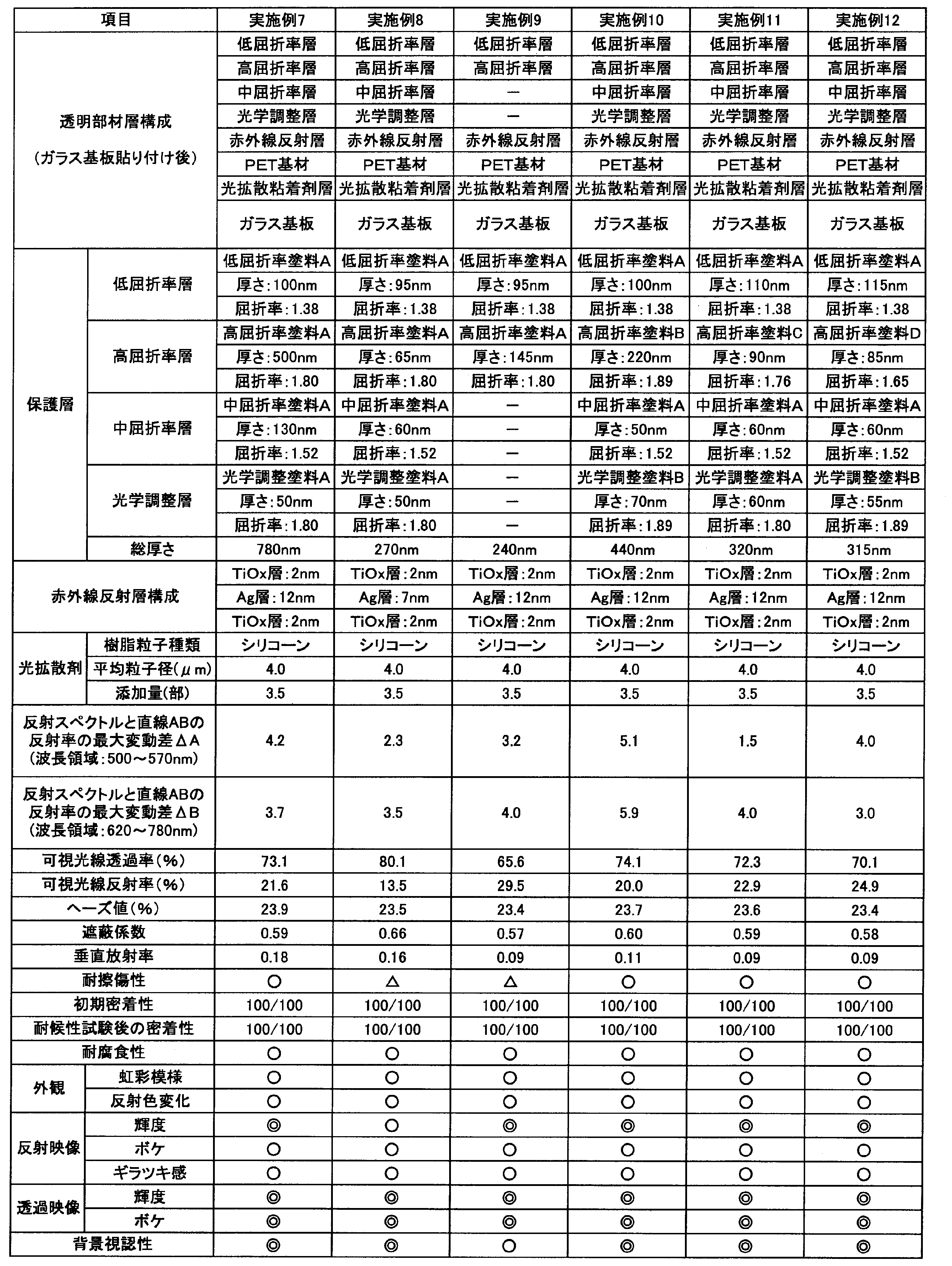
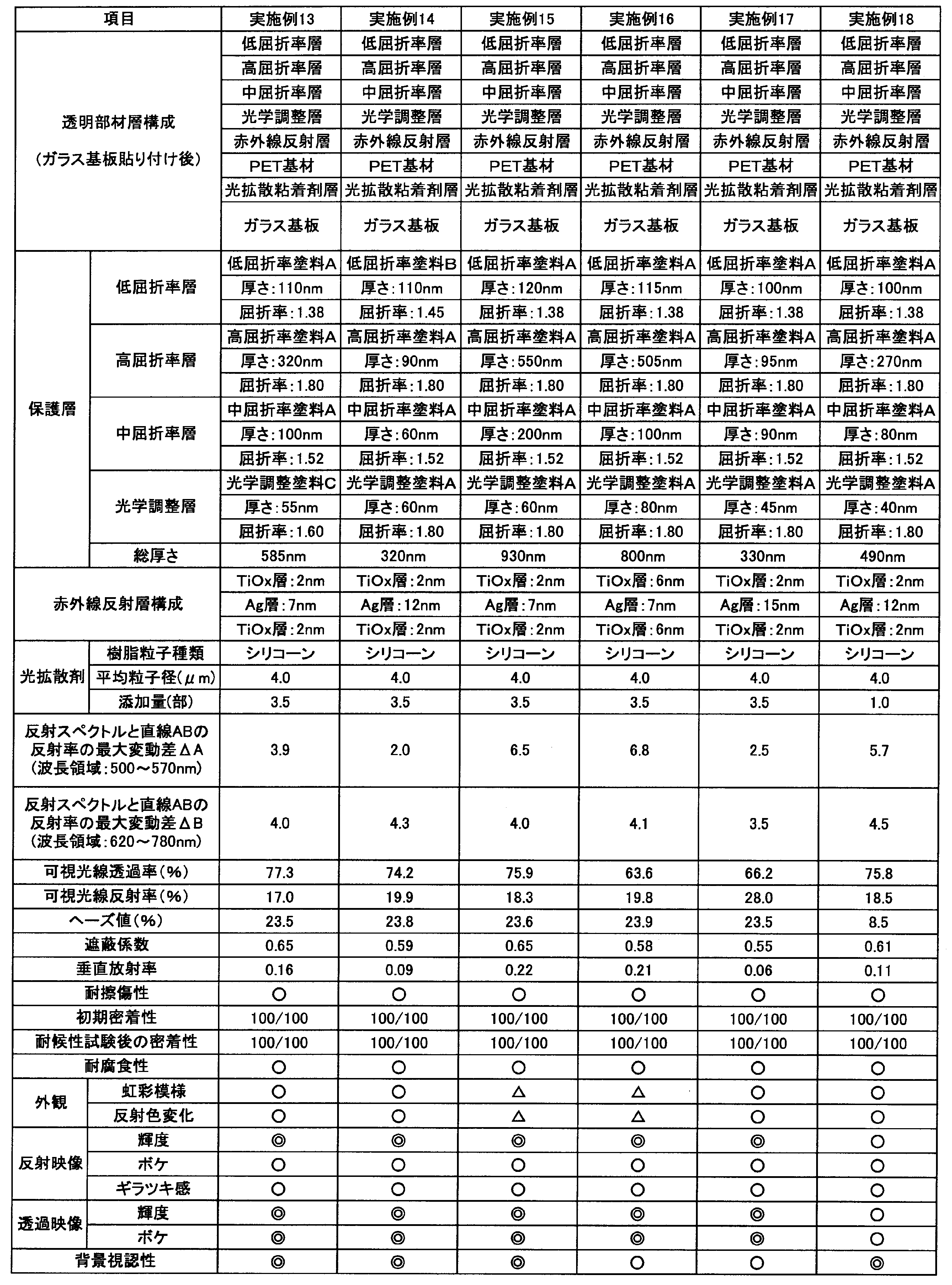

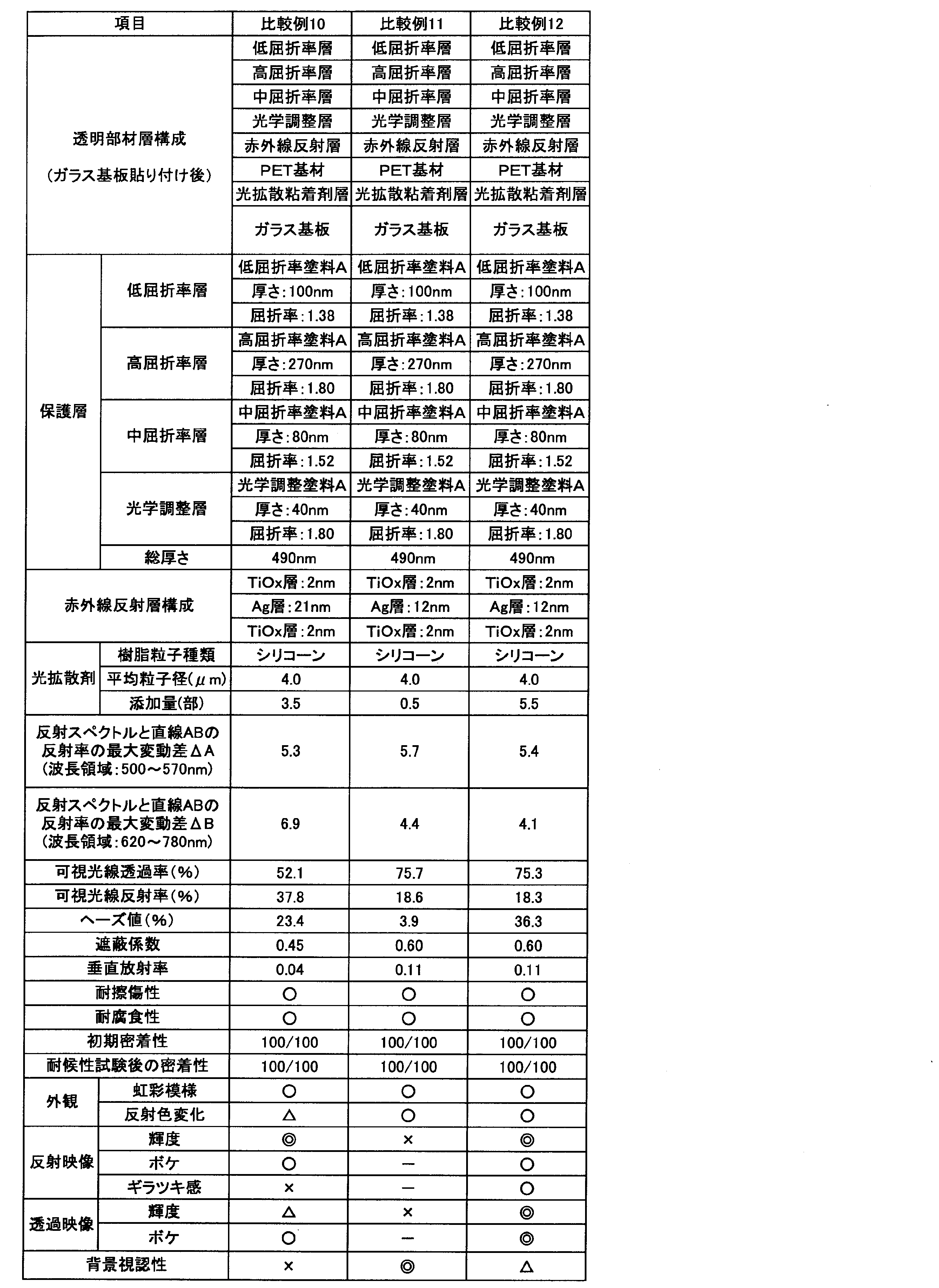
11 透明基材
12、14 金属亜酸化物層
13 金属層
15 光学調整層
16 中屈折率層
17 高屈折率層
18 低屈折率層
19 光拡散層
21 赤外線反射層
22、26 保護層
23 粘着剤層
24 光拡散粘着剤層
25 ガラス板
90 透明遮熱断熱部材
100 透明スクリーン
Claims (10)
- 透明基材と、赤外線反射層と、保護層と、光拡散層とを含む透明遮熱断熱部材であって、
前記透明遮熱断熱部材は、前記透明基材側から前記赤外線反射層及び前記保護層をこの順に含み、
前記光拡散層は、前記透明基材の前記赤外線反射層が形成された面とは反対側もしくは前記透明基材と前記赤外線反射層との間に形成され、
前記赤外線反射層は、少なくとも金属層、及び、金属が部分酸化された金属亜酸化物層を含み、
前記保護層は、総厚さが200nm~980nmであり、前記赤外線反射層側から少なくとも高屈折率層及び低屈折率層をこの順に含み、
前記光拡散層は、光拡散性粒子と、前記光拡散性粒子を保持する透明樹脂とを含み、
前記透明遮熱断熱部材は、
JIS R3106-1998に準じて測定した可視光線反射率が、12%以上30%以下であり、
JIS K7136-2000に準じて測定したヘーズ値が、5%以上35%以下であり、
JIS A5759-2008に準じて測定した遮蔽係数が、0.69以下であり、
JIS R3106-2008に準じて測定した垂直放射率が、0.22以下であることを特徴とする透明遮熱断熱部材。 - 前記透明遮熱断熱部材をスクリーンとした際に、プロジェクターから前記スクリーンに投影された映像をプロジェクター側からは反射映像として、また、前記スクリーンを挟んでプロジェクターの反対側からは透過映像として、両面から視認することができる請求項1に記載の透明遮熱断熱部材。
- 前記金属が部分酸化された金属亜酸化物層の厚さが、1~8nmである請求項1又は2に記載の透明遮熱断熱部材。
- 前記保護層は、前記赤外線反射層側から、中屈折率層、高屈折率層及び低屈折率層をこの順に含む請求項1~3のいずれか1項に記載の透明遮熱断熱部材。
- 前記保護層は、前記赤外線反射層側から、光学調整層、中屈折率層、高屈折率層及び低屈折率層をこの順で含み、
前記光学調整層は、波長550nmの屈折率が1.60~2.00であり、厚さが30~80nmの範囲の中から設定され、
前記中屈折率層は、波長550nmの屈折率が1.45~1.55であり、厚さが40~200nmの範囲の中から設定され、
前記高屈折率層は、波長550nmの屈折率が1.65~1.95であり、厚さが60~550nmの範囲の中から設定され、
前記低屈折率層は、波長550nmの屈折率が1.30~1.45であり、厚さが70~150nmの範囲の中から設定された請求項1~3のいずれか1項に記載の透明遮熱断熱部材。 - 前記金属が部分酸化された金属亜酸化物層は、チタン成分を含む請求項1~5のいずれか1項に記載の透明遮熱断熱部材。
- 前記保護層の前記赤外線反射層に接する層が、酸化チタン微粒子を含む請求項1~6のいずれか1項に記載の透明遮熱断熱部材。
- JIS R3106-1998に準じて測定した反射スペクトルにおいて、
前記反射スペクトルの波長500~570nmの範囲における最大反射率と最小反射率の平均値を示す仮想ラインa上の波長535nmに対応する点を点Aとし、
前記反射スペクトルの波長620~780nmの範囲における最大反射率と最小反射率の平均値を示す仮想ラインb上の波長700nmに対応する点を点Bとし、
前記点Aと前記点Bとを通る直線を波長500~780nmの範囲で延長して基準直線ABとし、
波長500~570nmの範囲における前記反射スペクトルの反射率の値と前記基準直線ABの反射率の値を比較した際に、各々の反射率の値の差が最大となる波長におけるその反射率の値の差の絶対値を最大変動差△Aと定義した時に、前記最大変動差△Aの値が反射率の%単位で7%以下であり、
波長620~780nmの範囲における前記反射スペクトルの反射率の値と前記基準直線ABの反射率の値を比較した際に、各々の反射率の値の差が最大となる波長におけるその反射率の値の差の絶対値を最大変動差△Bと定義した時に、前記最大変動差△Bの値が反射率の%単位で9%以下である請求項1~7のいずれか1項に記載の透明遮熱断熱部材。 - 前記透明基材の前記赤外線反射層が形成された面とは反対側に、最外層として粘着剤層を更に含む請求項1に記載の透明遮熱断熱部材。
- 前記光拡散層は、前記透明基材の前記赤外線反射層が形成された面とは反対側に最外層として配置され、前記光拡散層に含まれる前記透明樹脂が、粘着剤である請求項1に記載の透明遮熱断熱部材。
Priority Applications (4)
| Application Number | Priority Date | Filing Date | Title |
|---|---|---|---|
| CN201780056697.6A CN109716179A (zh) | 2016-10-18 | 2017-10-18 | 透明隔热绝热部件 |
| EP17863035.6A EP3531175A4 (en) | 2016-10-18 | 2017-10-18 | THERMAL INSULATING ELEMENT FOR TRANSPARENT THERMAL PROTECTION |
| JP2018546388A JPWO2018074527A1 (ja) | 2016-10-18 | 2017-10-18 | 透明遮熱断熱部材 |
| KR1020197007285A KR20190072514A (ko) | 2016-10-18 | 2017-10-18 | 투명 차열 단열 부재 |
Applications Claiming Priority (2)
| Application Number | Priority Date | Filing Date | Title |
|---|---|---|---|
| JP2016204093 | 2016-10-18 | ||
| JP2016-204093 | 2016-10-18 |
Publications (1)
| Publication Number | Publication Date |
|---|---|
| WO2018074527A1 true WO2018074527A1 (ja) | 2018-04-26 |
Family
ID=62019163
Family Applications (1)
| Application Number | Title | Priority Date | Filing Date |
|---|---|---|---|
| PCT/JP2017/037736 WO2018074527A1 (ja) | 2016-10-18 | 2017-10-18 | 透明遮熱断熱部材 |
Country Status (5)
| Country | Link |
|---|---|
| EP (1) | EP3531175A4 (ja) |
| JP (1) | JPWO2018074527A1 (ja) |
| KR (1) | KR20190072514A (ja) |
| CN (1) | CN109716179A (ja) |
| WO (1) | WO2018074527A1 (ja) |
Cited By (5)
| Publication number | Priority date | Publication date | Assignee | Title |
|---|---|---|---|---|
| WO2020138235A1 (ja) * | 2018-12-26 | 2020-07-02 | Agc株式会社 | 機能性フィルム及び機能性合わせガラス |
| JP2020166014A (ja) * | 2019-03-28 | 2020-10-08 | 大日本印刷株式会社 | 反射スクリーン、該反射スクリーンを用いた投射システム、及び反射スクリーンの製造方法 |
| JPWO2020208935A1 (ja) * | 2019-04-11 | 2020-10-15 | ||
| JP2022173038A (ja) * | 2021-05-06 | 2022-11-17 | カンブリオス フィルム ソリューションズ(シアメン) コーポレーション | 透明断熱フィルム |
| US11524484B1 (en) | 2021-06-15 | 2022-12-13 | Cambrios Film Solutions Corporation | Transparent heat-insulating film |
Families Citing this family (4)
| Publication number | Priority date | Publication date | Assignee | Title |
|---|---|---|---|---|
| JP2021004911A (ja) * | 2019-06-25 | 2021-01-14 | 恵和株式会社 | 拡散シート、バックライトユニット、液晶表示装置、及び、情報機器 |
| JP7446168B2 (ja) * | 2020-06-24 | 2024-03-08 | マクセル株式会社 | 透明遮熱断熱部材及びその製造方法 |
| US20220236464A1 (en) * | 2021-01-26 | 2022-07-28 | Viavi Solutions Inc. | Optical device with at least one infrared reflective material |
| CN113433788B (zh) * | 2021-07-09 | 2023-07-28 | 广西中光影光电有限公司 | 正投透明全息投影屏幕 |
Citations (18)
| Publication number | Priority date | Publication date | Assignee | Title |
|---|---|---|---|---|
| JPS4822104B1 (ja) | 1968-08-22 | 1973-07-03 | American Standard Inc | |
| JPS5214577B1 (ja) | 1970-06-01 | 1977-04-22 | ||
| JP3993980B2 (ja) | 1999-12-22 | 2007-10-17 | 株式会社きもと | 透視可能な透過型スクリーン |
| JP4190657B2 (ja) | 1999-05-14 | 2008-12-03 | リンテック株式会社 | 赤外線遮蔽フィルム |
| JP2010527816A (ja) * | 2007-05-23 | 2010-08-19 | スリーエム イノベイティブ プロパティズ カンパニー | 光拡散日射制御フィルム |
| JP2011133721A (ja) * | 2009-12-25 | 2011-07-07 | Tokai Rubber Ind Ltd | 透明積層フィルム |
| JP4822104B2 (ja) * | 2005-01-21 | 2011-11-24 | 大日本印刷株式会社 | 投影システム |
| JP2013210454A (ja) | 2012-03-30 | 2013-10-10 | Mitsubishi Paper Mills Ltd | 透過型スクリーン |
| JP2014141015A (ja) | 2013-01-24 | 2014-08-07 | Toray Ind Inc | 積層フィルム |
| JP2014167617A (ja) | 2013-01-31 | 2014-09-11 | Nitto Denko Corp | 赤外線反射フィルム |
| JP2014170171A (ja) | 2013-03-05 | 2014-09-18 | Toppan Printing Co Ltd | 反射防止機能を有する透明遮熱フィルム |
| JP2016009149A (ja) | 2014-06-26 | 2016-01-18 | 平岡織染株式会社 | 透過投映スクリーン |
| JP2016016611A (ja) * | 2014-07-09 | 2016-02-01 | 日立マクセル株式会社 | 透明遮熱断熱部材及びその製造方法 |
| JP2016075776A (ja) * | 2014-10-06 | 2016-05-12 | 大日本印刷株式会社 | 光学フィルム、映像源ユニット、及び表示装置 |
| JP2016161917A (ja) * | 2015-03-05 | 2016-09-05 | 日立マクセル株式会社 | 透明遮熱断熱部材及びその製造方法 |
| JP2016186627A (ja) * | 2015-03-27 | 2016-10-27 | 日立マクセル株式会社 | 透明スクリーン機能を備えた透明遮熱部材 |
| JP2017053967A (ja) * | 2015-09-08 | 2017-03-16 | 日立マクセル株式会社 | 透明遮熱断熱部材及びその製造方法 |
| WO2017131174A1 (ja) * | 2016-01-29 | 2017-08-03 | 日立マクセル株式会社 | 透明スクリーン機能を備えた透明遮熱断熱部材 |
Family Cites Families (5)
| Publication number | Priority date | Publication date | Assignee | Title |
|---|---|---|---|---|
| JPS5214577A (en) | 1975-07-25 | 1977-02-03 | Nikkei Giken:Kk | Contacting apparatus |
| JP4342821B2 (ja) * | 2003-04-03 | 2009-10-14 | 日東電工株式会社 | 光学素子、液晶セル、照明装置および液晶表示装置 |
| KR20130048718A (ko) * | 2010-03-01 | 2013-05-10 | 시피필름스 인코포레이션 | 낮은 방사율 및 emi 차폐 창 필름 |
| JP6641688B2 (ja) * | 2014-12-08 | 2020-02-05 | 大日本印刷株式会社 | カラーフィルタおよび表示装置 |
| KR20160115849A (ko) * | 2015-03-27 | 2016-10-06 | 히다치 막셀 가부시키가이샤 | 투명 스크린 기능을 구비한 투명 차열 부재 |
-
2017
- 2017-10-18 CN CN201780056697.6A patent/CN109716179A/zh active Pending
- 2017-10-18 KR KR1020197007285A patent/KR20190072514A/ko unknown
- 2017-10-18 WO PCT/JP2017/037736 patent/WO2018074527A1/ja unknown
- 2017-10-18 EP EP17863035.6A patent/EP3531175A4/en not_active Withdrawn
- 2017-10-18 JP JP2018546388A patent/JPWO2018074527A1/ja active Pending
Patent Citations (18)
| Publication number | Priority date | Publication date | Assignee | Title |
|---|---|---|---|---|
| JPS4822104B1 (ja) | 1968-08-22 | 1973-07-03 | American Standard Inc | |
| JPS5214577B1 (ja) | 1970-06-01 | 1977-04-22 | ||
| JP4190657B2 (ja) | 1999-05-14 | 2008-12-03 | リンテック株式会社 | 赤外線遮蔽フィルム |
| JP3993980B2 (ja) | 1999-12-22 | 2007-10-17 | 株式会社きもと | 透視可能な透過型スクリーン |
| JP4822104B2 (ja) * | 2005-01-21 | 2011-11-24 | 大日本印刷株式会社 | 投影システム |
| JP2010527816A (ja) * | 2007-05-23 | 2010-08-19 | スリーエム イノベイティブ プロパティズ カンパニー | 光拡散日射制御フィルム |
| JP2011133721A (ja) * | 2009-12-25 | 2011-07-07 | Tokai Rubber Ind Ltd | 透明積層フィルム |
| JP2013210454A (ja) | 2012-03-30 | 2013-10-10 | Mitsubishi Paper Mills Ltd | 透過型スクリーン |
| JP2014141015A (ja) | 2013-01-24 | 2014-08-07 | Toray Ind Inc | 積層フィルム |
| JP2014167617A (ja) | 2013-01-31 | 2014-09-11 | Nitto Denko Corp | 赤外線反射フィルム |
| JP2014170171A (ja) | 2013-03-05 | 2014-09-18 | Toppan Printing Co Ltd | 反射防止機能を有する透明遮熱フィルム |
| JP2016009149A (ja) | 2014-06-26 | 2016-01-18 | 平岡織染株式会社 | 透過投映スクリーン |
| JP2016016611A (ja) * | 2014-07-09 | 2016-02-01 | 日立マクセル株式会社 | 透明遮熱断熱部材及びその製造方法 |
| JP2016075776A (ja) * | 2014-10-06 | 2016-05-12 | 大日本印刷株式会社 | 光学フィルム、映像源ユニット、及び表示装置 |
| JP2016161917A (ja) * | 2015-03-05 | 2016-09-05 | 日立マクセル株式会社 | 透明遮熱断熱部材及びその製造方法 |
| JP2016186627A (ja) * | 2015-03-27 | 2016-10-27 | 日立マクセル株式会社 | 透明スクリーン機能を備えた透明遮熱部材 |
| JP2017053967A (ja) * | 2015-09-08 | 2017-03-16 | 日立マクセル株式会社 | 透明遮熱断熱部材及びその製造方法 |
| WO2017131174A1 (ja) * | 2016-01-29 | 2017-08-03 | 日立マクセル株式会社 | 透明スクリーン機能を備えた透明遮熱断熱部材 |
Non-Patent Citations (1)
| Title |
|---|
| See also references of EP3531175A4 * |
Cited By (10)
| Publication number | Priority date | Publication date | Assignee | Title |
|---|---|---|---|---|
| WO2020138235A1 (ja) * | 2018-12-26 | 2020-07-02 | Agc株式会社 | 機能性フィルム及び機能性合わせガラス |
| JPWO2020138235A1 (ja) * | 2018-12-26 | 2021-11-18 | Agc株式会社 | 機能性フィルム及び機能性合わせガラス |
| JP7359162B2 (ja) | 2018-12-26 | 2023-10-11 | Agc株式会社 | 機能性フィルム及び機能性合わせガラス |
| JP2020166014A (ja) * | 2019-03-28 | 2020-10-08 | 大日本印刷株式会社 | 反射スクリーン、該反射スクリーンを用いた投射システム、及び反射スクリーンの製造方法 |
| JP7331412B2 (ja) | 2019-03-28 | 2023-08-23 | 大日本印刷株式会社 | 反射スクリーン、該反射スクリーンを用いた投射システム、及び反射スクリーンの製造方法 |
| JPWO2020208935A1 (ja) * | 2019-04-11 | 2020-10-15 | ||
| WO2020208935A1 (ja) * | 2019-04-11 | 2020-10-15 | 株式会社nittoh | 光学フィルター及び撮影レンズユニット |
| JP2022173038A (ja) * | 2021-05-06 | 2022-11-17 | カンブリオス フィルム ソリューションズ(シアメン) コーポレーション | 透明断熱フィルム |
| JP7197655B2 (ja) | 2021-05-06 | 2022-12-27 | カンブリオス フィルム ソリューションズ(シアメン) コーポレーション | 透明断熱フィルム |
| US11524484B1 (en) | 2021-06-15 | 2022-12-13 | Cambrios Film Solutions Corporation | Transparent heat-insulating film |
Also Published As
| Publication number | Publication date |
|---|---|
| KR20190072514A (ko) | 2019-06-25 |
| JPWO2018074527A1 (ja) | 2019-08-08 |
| CN109716179A (zh) | 2019-05-03 |
| EP3531175A4 (en) | 2020-07-08 |
| EP3531175A1 (en) | 2019-08-28 |
Similar Documents
| Publication | Publication Date | Title |
|---|---|---|
| WO2017131174A1 (ja) | 透明スクリーン機能を備えた透明遮熱断熱部材 | |
| WO2018074527A1 (ja) | 透明遮熱断熱部材 | |
| US10132972B2 (en) | Optical element and method for producing the same | |
| US9678256B2 (en) | Transparent heat-shielding member | |
| JP6553897B2 (ja) | 透明遮熱断熱部材及びその製造方法 | |
| JP6533437B2 (ja) | 透明遮熱断熱部材及びその製造方法 | |
| JP5878056B2 (ja) | ハードコート基材及びそれを用いた透明導電性フィルム | |
| JP6328984B2 (ja) | 両面透明導電性フィルムおよびタッチパネル | |
| WO2016068087A1 (ja) | 透過型透明スクリーン、映像表示システムおよび映像表示方法 | |
| JP2003080624A (ja) | 透明導電材料およびタッチパネル | |
| TW201318849A (zh) | 具有光控制功能的陽光控制窗膜 | |
| JP5499837B2 (ja) | 熱線遮蔽フィルム | |
| JPWO2019107036A1 (ja) | ハードコートフィルム、光学積層体および画像表示装置 | |
| JP2004047456A (ja) | 透明導電材料およびタッチパネル | |
| JP6584819B2 (ja) | 透明スクリーン機能を備えた透明遮熱部材 | |
| JP4285059B2 (ja) | 透明導電性材料及びタッチパネル | |
| JP7035381B2 (ja) | 光学フィルム、画像表示装置又はタッチパネル | |
| JP6783348B2 (ja) | 透明遮熱断熱部材及びその製造方法 |
Legal Events
| Date | Code | Title | Description |
|---|---|---|---|
| 121 | Ep: the epo has been informed by wipo that ep was designated in this application |
Ref document number: 17863035 Country of ref document: EP Kind code of ref document: A1 |
|
| ENP | Entry into the national phase |
Ref document number: 2018546388 Country of ref document: JP Kind code of ref document: A |
|
| ENP | Entry into the national phase |
Ref document number: 20197007285 Country of ref document: KR Kind code of ref document: A |
|
| NENP | Non-entry into the national phase |
Ref country code: DE |
|
| ENP | Entry into the national phase |
Ref document number: 2017863035 Country of ref document: EP Effective date: 20190520 |