WO2018070146A1 - 光学フィルムの製造方法 - Google Patents
光学フィルムの製造方法 Download PDFInfo
- Publication number
- WO2018070146A1 WO2018070146A1 PCT/JP2017/032198 JP2017032198W WO2018070146A1 WO 2018070146 A1 WO2018070146 A1 WO 2018070146A1 JP 2017032198 W JP2017032198 W JP 2017032198W WO 2018070146 A1 WO2018070146 A1 WO 2018070146A1
- Authority
- WO
- WIPO (PCT)
- Prior art keywords
- dope
- film
- solvent
- resin
- mass
- Prior art date
- Legal status (The legal status is an assumption and is not a legal conclusion. Google has not performed a legal analysis and makes no representation as to the accuracy of the status listed.)
- Ceased
Links
Images
Classifications
-
- B—PERFORMING OPERATIONS; TRANSPORTING
- B29—WORKING OF PLASTICS; WORKING OF SUBSTANCES IN A PLASTIC STATE IN GENERAL
- B29C—SHAPING OR JOINING OF PLASTICS; SHAPING OF MATERIAL IN A PLASTIC STATE, NOT OTHERWISE PROVIDED FOR; AFTER-TREATMENT OF THE SHAPED PRODUCTS, e.g. REPAIRING
- B29C41/00—Shaping by coating a mould, core or other substrate, i.e. by depositing material and stripping-off the shaped article; Apparatus therefor
- B29C41/24—Shaping by coating a mould, core or other substrate, i.e. by depositing material and stripping-off the shaped article; Apparatus therefor for making articles of indefinite length
-
- C—CHEMISTRY; METALLURGY
- C08—ORGANIC MACROMOLECULAR COMPOUNDS; THEIR PREPARATION OR CHEMICAL WORKING-UP; COMPOSITIONS BASED THEREON
- C08J—WORKING-UP; GENERAL PROCESSES OF COMPOUNDING; AFTER-TREATMENT NOT COVERED BY SUBCLASSES C08B, C08C, C08F, C08G or C08H
- C08J3/00—Processes of treating or compounding macromolecular substances
- C08J3/02—Making solutions, dispersions, lattices or gels by other methods than by solution, emulsion or suspension polymerisation techniques
- C08J3/09—Making solutions, dispersions, lattices or gels by other methods than by solution, emulsion or suspension polymerisation techniques in organic liquids
- C08J3/091—Making solutions, dispersions, lattices or gels by other methods than by solution, emulsion or suspension polymerisation techniques in organic liquids characterised by the chemical constitution of the organic liquid
- C08J3/093—Halogenated hydrocarbons
-
- C—CHEMISTRY; METALLURGY
- C08—ORGANIC MACROMOLECULAR COMPOUNDS; THEIR PREPARATION OR CHEMICAL WORKING-UP; COMPOSITIONS BASED THEREON
- C08J—WORKING-UP; GENERAL PROCESSES OF COMPOUNDING; AFTER-TREATMENT NOT COVERED BY SUBCLASSES C08B, C08C, C08F, C08G or C08H
- C08J5/00—Manufacture of articles or shaped materials containing macromolecular substances
- C08J5/18—Manufacture of films or sheets
-
- C—CHEMISTRY; METALLURGY
- C08—ORGANIC MACROMOLECULAR COMPOUNDS; THEIR PREPARATION OR CHEMICAL WORKING-UP; COMPOSITIONS BASED THEREON
- C08L—COMPOSITIONS OF MACROMOLECULAR COMPOUNDS
- C08L65/00—Compositions of macromolecular compounds obtained by reactions forming a carbon-to-carbon link in the main chain; Compositions of derivatives of such polymers
-
- C—CHEMISTRY; METALLURGY
- C08—ORGANIC MACROMOLECULAR COMPOUNDS; THEIR PREPARATION OR CHEMICAL WORKING-UP; COMPOSITIONS BASED THEREON
- C08L—COMPOSITIONS OF MACROMOLECULAR COMPOUNDS
- C08L67/00—Compositions of polyesters obtained by reactions forming a carboxylic ester link in the main chain; Compositions of derivatives of such polymers
-
- C—CHEMISTRY; METALLURGY
- C08—ORGANIC MACROMOLECULAR COMPOUNDS; THEIR PREPARATION OR CHEMICAL WORKING-UP; COMPOSITIONS BASED THEREON
- C08L—COMPOSITIONS OF MACROMOLECULAR COMPOUNDS
- C08L79/00—Compositions of macromolecular compounds obtained by reactions forming in the main chain of the macromolecule a linkage containing nitrogen with or without oxygen or carbon only, not provided for in groups C08L61/00 - C08L77/00
- C08L79/04—Polycondensates having nitrogen-containing heterocyclic rings in the main chain; Polyhydrazides; Polyamide acids or similar polyimide precursors
- C08L79/08—Polyimides; Polyester-imides; Polyamide-imides; Polyamide acids or similar polyimide precursors
-
- G—PHYSICS
- G02—OPTICS
- G02B—OPTICAL ELEMENTS, SYSTEMS OR APPARATUS
- G02B1/00—Optical elements characterised by the material of which they are made; Optical coatings for optical elements
- G02B1/04—Optical elements characterised by the material of which they are made; Optical coatings for optical elements made of organic materials, e.g. plastics
-
- G—PHYSICS
- G02—OPTICS
- G02B—OPTICAL ELEMENTS, SYSTEMS OR APPARATUS
- G02B5/00—Optical elements other than lenses
- G02B5/30—Polarising elements
Definitions
- the present invention relates to a method for producing an optical film containing a polyimide resin, a polyarylate resin or a cycloolefin resin.
- various optical films for example, a transparent protective film for protecting the polarizing element of the polarizing plate
- a transparent resin film containing a polyimide resin, a polyarylate resin, a cycloolefin resin, or the like is used for an optical film, mainly an optical compensation film for a liquid crystal display device.
- Such an optical film is often manufactured as a long resin film by, for example, a solution casting (film formation) method.
- resins such as polyimide resin, polyarylate resin, and cycloolefin resin are synthetic polymers, and contain residual monomers, antioxidants, catalysts, and the like as impurities during production. If such residual monomer is present, process contamination may occur during drying. In addition, there is a problem that internal haze increases due to impurities (antioxidants, catalysts, etc.) in the resin remaining in the film.
- the dope may be discharged at the same time because it is precipitated by forming a complex between the resin impurities and the chelating agent.
- the present invention has been made in view of such circumstances, and without using a chelating agent, impurities of doping can be efficiently removed, and a high-quality polyimide resin, polyarylate resin or cycloolefin resin with low internal haze is obtained. It aims at providing the method of manufacturing the optical film to contain.
- a method for producing an optical film according to one embodiment of the present invention is a solution casting film-forming method, in which a polyimide resin, a polyarylate resin, or a cycloolefin resin, at least one alcohol solvent, and at least one for the resin are used.
- a dope containing various good solvents was prepared, the optical dope was cast on a support, a web (casting film) was formed on the support, the web was peeled off from the support, and then peeled off
- the method for producing an optical film by winding and drying a web the method further comprises the step of further adding a good solvent to the dope after the dope is adjusted, and the step of removing the good solvent thereafter.
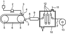
- FIG. 1 is a schematic view showing a basic configuration of an optical film manufacturing apparatus by a solution casting method using an endless belt support.
- the method for producing an optical film according to the present embodiment includes a polyimide resin, a polyarylate resin or a cycloolefin resin, at least one alcohol solvent, and a good solvent for at least one resin in a solution casting film forming method. Adjusting the dope, casting the optical dope on a support, forming a web (casting film) on the support, peeling the web from the support, and then winding the peeled web; In the method for producing an optical film by drying, after the dope is prepared, the method further includes a step of adding a good solvent to the dope, and then a step of removing the good solvent.
- an optical film containing a high-quality polyimide resin, polyarylate resin or cycloolefin resin having a low internal haze is efficiently produced by removing impurities in the dope without using a chelating agent.
- a method can be provided.
- the dope is a resin solution used as a film raw material, and after being cast on a support, the dope is gelled and has a hardness as a film is called a web (cast film). That is, the film in the process of drying up to the finished optical film is referred to as a web.
- a web the film in the process of drying up to the finished optical film.
- the boundary between the dome film formed with the dope, the web and the film is not exactly defined.
- FIG. 1 is an explanatory diagram showing a schematic configuration of an optical film manufacturing apparatus used in the present embodiment.
- a dope containing a polymer (polyimide resin, polyarylate resin or cycloolefin resin) and a solvent is cast from a casting die on a traveling support, and then as a film.
- a solution casting method that peels off is used.
- symbol means the following.
- a polyimide resin, a polyarylate resin or a cycloolefin resin is dissolved in a mixed solvent of a good solvent and a poor solvent in the melting pot 1, and additives such as a matting agent and an ultraviolet absorber are added thereto as necessary.
- a resin solution (dope) is prepared.
- the preparation method of each dope, a good solvent, and a poor solvent are mentioned later.
- the dope removes insoluble matters and foreign matters by filtration.
- the filter medium to be used is not limited so long as it can remove insoluble matters without causing clogging.
- a filter medium having an absolute filtration accuracy of 0.008 mm or less, preferably 0.003 to 0.006 mm is used. It is preferable to use it.
- the dope adjusted in the melting pot 1 is fed to the casting die 3 by a conduit through a pressurized metering gear pump 2, and cast on a support 6 made of a rotationally driven stainless steel endless belt that is infinitely transported.
- the dope is cast from the casting die 3 at a position, thereby forming a web 8 as a casting film on the support 6.
- the dope is cast by the casting die 3 using a doctor blade method in which the film thickness of the cast web is adjusted by a blade, a method by a reverse roll coater in which the film thickness is adjusted by a reverse rotating roll, There is a method using a pressure die. Among them, a method using a pressure die is preferable because the slit shape of the base portion can be adjusted and the film thickness can be easily made uniform.
- the pressure die includes a coat hanger die and a T die, and any of them can be preferably used.
- the support 6 is held by a pair of front and rear drums 5 and 5 and a plurality of intermediate rolls (not shown).
- One or both of the drums 5 and 5 are provided with a driving device (not shown) for applying tension to the support body 6, whereby the support body 6 is used in a tensioned state.
- the width of the support 6 is preferably about 1000 to 4000 mm, and the width of the film after winding is preferably about 1000 to 2500 mm.
- the wide optical film for liquid crystal display devices can be manufactured by a metal support body system.
- the belt temperature during film formation is ⁇ 50 ° C. to less than the boiling point of the solvent in the general temperature range, but less than the boiling point of the solvent having the lowest boiling point in the mixed solvent.
- the temperature is preferably in the range of 5 ° C. to 70 ° C., more preferably in the range of 5 to 40 ° C. At this time, it is necessary to control the ambient atmospheric humidity above the dew point.
- the moving speed of the support 6 under production conditions is 5 m min or more, preferably 10 to 180 m / min, more preferably 80 m / min to 150 m / min.
- the dope cast on the support 6 in this way also increases the strength of the gel film (film strength) by promoting drying until stripping.
- the web 8 formed by the dope cast on the support 6 is heated on the support 6, and the solvent is evaporated until the web can be peeled from the support 6 by the peeling roll 7.
- the web on the support after casting is preferably dried on the support in an atmosphere of 30 to 100 ° C. In order to maintain the atmosphere at 30 to 100 ° C., it is preferable to apply hot air at this temperature to the upper surface of the web or heat by means such as infrared rays.
- the web temperature when peeling the web 8 from the support 6 is preferably ⁇ 50 to 60 ° C., further 10 to 40 ° C., and more preferably 11 to 30 ° C.
- the residual solvent amount of the web on the metal support at the time of peeling is preferably in the range of 15 to 100% by mass.
- the residual solvent amount is preferably controlled by the drying temperature and drying time in the solvent evaporation step.
- the residual solvent amount of the web or film is defined by the following formula (Z).
- Residual solvent amount (%) (mass before heat treatment of web or film ⁇ mass after heat treatment of web or film) / (mass after heat treatment of web or film) ⁇ 100 Note that the heat treatment for measuring the residual solvent amount represents performing heat treatment at 115 ° C. for 1 hour.
- the peeling tension when peeling the support 6 and the web 8 by the peeling roll 7 is larger than the peeling force obtained by measuring the peeling force as in JISJZ 0237. If it is equivalent to the peel force obtained by the measurement method, the peel position may be taken downstream, so it is increased for stabilization. In addition, even if it forms into a film with the same peeling tension in a process, if the peeling force by a JIS measuring method falls, it has also been confirmed that the variation in the cross nicols permeability (CNT) of a film reduces significantly.
- CNT cross nicols permeability
- the peel tension value in the process is usually 20 to 400 N / m.
- the residual solvent amount of the web 8 is large at the time of peeling, and it is easy to extend in the conveying direction. For this reason, the film tends to shrink in the width direction, and when drying and shrinkage overlap, the end curls and folds, so that wrinkles are likely to occur.
- the peeling tension is from the lowest tension that can be peeled to 190 N / m.
- a belt-like support is illustrated as the support, but the support of the present embodiment is not limited to a belt-like support.
- a drum-like support may be used. .
- the web 8 After drying and solidifying until the web 8 has a peelable film strength on the support 6, the web 8 is peeled off by a peeling roll 7, and then the web 8 is stretched in a tenter 9 in a stretching process.
- the manufacturing method of the present embodiment may include a stretching process for stretching the obtained web.
- a stretching process for stretching the obtained web.
- a stretching device tenter 9
- the target retardation value Ro in the in-plane direction and retardation value Rt in the thickness direction can be obtained.
- a tenter method in which both side edges of the web 8 are fixed with clips or the like is preferably stretched in order to improve the flatness and dimensional stability of the film.
- the amount of residual solvent at the start of stretching is preferably 1% by mass or more and less than 25% by mass. More preferably, it is in the range of 5 to 20% by mass.
- the optical film of the present embodiment is preferably stretched in the longitudinal direction (also referred to as MD direction and casting direction) and / or in the lateral direction (also referred to as TD direction), and at least in the lateral direction by a stretching device. It is preferable to produce by stretching.
- the stretching operation may be performed in multiple stages.
- simultaneous biaxial stretching may be performed or may be performed stepwise.
- stepwise means that, for example, stretching in different stretching directions can be sequentially performed, stretching in the same direction is divided into multiple stages, and stretching in different directions is added to any one of the stages. Is also possible.
- the stretching temperature and stretching ratio can be appropriately set according to the resin used and desired film properties.
- the stretched film is heated and dried in the drying device 10.
- the web 8 is meandered by a plurality of conveying rolls 12 arranged in a staggered manner as viewed from the side, and the web 8 is dried in the meantime.
- the means for drying the web 8 is not particularly limited, and is generally performed with hot air, infrared rays, a heating roll, microwaves, or the like. It is preferable to dry with hot air from the point of simplicity.
- the web 8 can be dried by blowing the drying air 11 from the hot air inlet of the drying device 10 and exhausting the exhaust air from the outlet of the drying device 10, so that the optical film F can be obtained.
- the temperature of the drying air 11 is preferably 40 to 350 ° C., and the drying time is preferably about 5 seconds to 30 minutes.
- These steps from casting to conveyance drying may be performed in an air atmosphere or an inert gas atmosphere such as nitrogen gas.
- an inert gas atmosphere such as nitrogen gas.
- the dried film is taken up by the take-up device 13 to obtain the original roll of the optical film F.
- the residual solvent amount of the film at the end of drying 0.5% by mass or less, preferably 0.1% by mass or less, a film having good dimensional stability can be obtained.
- the winding method of the film may be a generally used winder, and there are methods for controlling the tension such as a constant torque method, a constant tension method, a taper tension method, a program tension control method with a constant internal stress, etc. Use it properly.
- the film may be bonded to the winding core (winding core) by either a double-sided adhesive tape or a single-sided adhesive tape.
- the optical film F preferably has a width of 1000 to 2500 mm after winding.
- the film thickness (final film thickness) after drying of the optical film of the present embodiment is preferably in the range of 5 to 40 ⁇ m as a finished film from the viewpoint of thinning the liquid crystal display device.
- the film thickness after drying refers to a film in which the amount of residual solvent in the film is 0.5% by mass or less.
- the method for producing an optical film according to this embodiment includes a polyimide resin, a polyarylate resin or a cycloolefin resin, at least one alcohol solvent, and the resin as a dope in the solution casting film forming method as described above.
- a major feature is that it includes a step of adjusting a dope containing at least one good solvent, a step of further adding a good solvent to the dope after the dope is adjusted, and a step of removing the good solvent thereafter. One of them.
- the dope preparation of this embodiment can be performed using a known dope manufacturing apparatus. Specifically, for example, by using a dope manufacturing apparatus having a supply port for introducing a material into the upper portion, a mixing pot having a rotating body for mixing the material, and a discharge port for taking out a sample mixed in the lower portion. Prepare dope.
- the dope preparation can be prepared by mixing materials and then using a high temperature dissolution method.
- the high temperature dissolution method the mixed solution is heated to a range of 30 to 200 ° C. under a pressure of 0.2 to 30 MPa.
- the temperature range is preferably in the range of 40 to 150 ° C., more preferably in the range of 40 to 100 ° C.
- the heating method for example, high-pressure steam may be used, or an electric heat source may be used.
- the mixing kettle is preferably a pressure-resistant pressure tank.
- the alcohol solvent used for the dope of this embodiment is not particularly limited, and examples thereof include methanol, ethanol, isopropanol, n-butanol, and 2-butanol. Among these, it is preferable to select from methanol, ethanol and butanol from the viewpoint of improving peelability and enabling high-speed casting. In particular, it is preferable to use methanol or ethanol.
- the concentration of the alcohol solvent when adjusting the dope is preferably about 2 to 30% by mass with respect to the total amount of the solvent.
- the ratio of the alcohol solvent in the solvent contained in the dope is in the above range, the web is appropriately gelled to facilitate peeling from the metal support, and the resin and other compounds can be dissolved in the organic solvent. It is thought to promote moderately.
- a more preferable ratio of the alcohol solvent in the total solvent is about 2 to 20% by mass.
- the good solvent used when preparing the dope of the present embodiment is not particularly limited as long as it is a solvent that easily solvates a polymer (resin).
- the good solvent means a solvent that is transparent in a state where 10% by mass or more of the resin constituting the dope is dissolved in the solvent.
- transparent means that ⁇ haze (dope filling haze ⁇ quartz cell haze) ⁇ 3.0, which is a dope haze when a dope is filled in a quartz cell and measured with a haze meter.
- More specific good solvents include, for example, chlorinated organic solvents such as dichloromethane and tetrachloromethane, and non-chlorinated organic solvents such as methyl acetate, ethyl acetate, amyl acetate, acetone, methyl ethyl ketone, tetrahydrofuran, 1, 3-dioxolane, 1,4-dioxane, cyclohexanone, ethyl formate, 2,2,2-trifluoroethanol, 2,2,3,3-hexafluoro-1-propanol, 1,3-difluoro-2-propanol, 1,1,1,3,3,3-hexafluoro-2-methyl-2-propanol, 1,1,1,3,3,3-hexafluoro-2-propanol, 2,2,3,3 3-pentafluoro-1-propanol, nitroethane, methanol, ethanol, n-propanol, iso-
- the resin is a polyarylate or cycloolefins in the case of dichloromethane
- the resin is polyimide tetrachloromethane.
- the good solvent used for the dope is preferably 55% by mass or more, more preferably 70% by mass or more, and still more preferably 80% by mass or more based on the total amount of the solvent contained in the dope.
- a dope is prepared using a mixed solvent containing at least one alcohol solvent and a good solvent as described above, and the good solvent is further added after the dope is prepared.
- the good solvent to be added include the same good solvents as described above.
- the good solvent used during dope preparation and the good solvent added after preparation may be the same solvent or different.
- the method of adding the good solvent to the dope is not particularly limited, but the good solvent prepared separately after the dope preparation may be added as it is, or the good solvent in the dope volatilized by heating at the time of dope preparation may be added. It is also possible to cool and return to droplets and add it by dropping it.
- the timing of adding the good solvent is not particularly limited, but it may volatilize even if the dope is hot, so the dope is supported after the temperature of the dope falls below the boiling point of the good solvent. It is preferable to add it until it is cast into the body.
- the addition amount of the good solvent after preparing the dope is preferably about 1 to 50% by mass with respect to the total amount of the dope. If the addition amount of the good solvent is within this range, the removal rate of impurities is increased, so that the quality of the produced film can be secured, and the dope loss can be reduced and the time can be reduced by removing the solvent. A more preferable addition amount is about 2 to 10% by mass with respect to the total amount of the dope.
- the manufacturing method of this embodiment further includes a step of removing the good solvent after adding the good solvent.
- the means for removing the good solvent is not particularly limited and can be removed by a conventionally known method. Specifically, for example, the solvent may be taken out from the discharge port of the above-described dope manufacturing apparatus, or the good solvent can be removed by branching the liquid feeding pipe and reusing / discarding only the solvent.
- the timing for removing the good solvent is not particularly limited, but for example, it is preferable to remove the good solvent before starting the feeding or during the change of the feeding tank.
- the amount of good solvent to be removed is preferably 80 to 100% by mass of the amount of good solvent to be added. If the removal amount of the good solvent is within this range, the removal rate of impurities is increased, so that the film quality can be ensured. A more preferable removal amount of the good solvent is about 90 to 100% by mass with respect to the amount of the good solvent to be added.
- the manufacturing method as described above it is possible to provide a method for manufacturing an optical film containing a high-quality polyimide resin, polyarylate resin or cycloolefin resin having a low internal haze, which can efficiently remove impurities from the dope. it can.
- the dope used for the polyimide resin-containing optical film in the present embodiment includes polyamic acid or polyimide as a main material.
- polyamic acid or polyimide having a weight average molecular weight of 30,000 to 1,000,000. More specifically, for example, polyamic acid or polyimide as described in JP-A-2016-64642 can be used.
- a mixed solvent containing at least one alcohol solvent and at least one good solvent is used. Especially, it is preferable to use the solvent containing 50 mass% or more of tetrachloromethane as a good solvent.
- a method for preparing a dope in which polyamic acid or polyimide is dissolved in a mixed solvent containing 50% by mass or more of tetrachloromethane include the following methods (i) to (iii). However, it is not limited to these methods.
- An aromatic, aliphatic or alicyclic tetracarboxylic acid or derivative thereof is preferably added to a solution of diamine or a derivative thereof, or preferably a solution of an aromatic, aliphatic or alicyclic tetracarboxylic acid component.
- a diamine or a derivative thereof is added to the mixture, and the polyamic acid solution is obtained by maintaining at a temperature of preferably 80 ° C. or lower (more preferably 30 ° C. or lower) for 0.5 to 3 hours.
- the solvent used here the above polymerization solvent is used.
- the dope according to the present invention can be obtained by replacing the polymerization solvent in the obtained polyamic acid solution with a mixed solvent containing tetrachloromethane and an alcohol solvent.
- a polyimide solution can be obtained by dehydrating the polyamic acid solution obtained in (i) above.
- the reaction temperature is preferably within a temperature range of ⁇ 20 to 50 ° C. when a ring closing catalyst is added, and is preferably within a temperature range of 80 to 300 ° C. when no ring closing catalyst is added. .
- the dope according to the present invention can be obtained by replacing the polymerization solvent in the polyimide solution obtained by any of the above methods with a mixed solvent containing tetrachloromethane and an alcohol solvent.
- the concentration of polyamic acid or polyimide in the dope prepared as described above is preferably 1 to 50% by mass, and more preferably 10 to 40% by mass. If it is 50 mass% or less, the surface flatness of the polyimide film obtained will become favorable.
- the viscosity of the dope a value measured with a Brookfield viscometer of 1000 to 100,000 cp, preferably 10,000 to 50,000 cp is preferable because stable liquid feeding is possible.
- additives can be added to the dope containing the polyamic acid or polyimide as necessary.
- Additives that can be used include inorganic fillers, surfactants, antioxidants, and other various functional materials (for example, conductive materials such as carbon nanotubes and nano metal materials, and ferroelectric materials such as barium titanate).
- conductive materials such as carbon nanotubes and nano metal materials, and ferroelectric materials such as barium titanate.
- ZnS Ag
- ZnS Cu
- Y 2 O 2 S Eu and other phosphors, ultraviolet absorbers, etc.
- flame retardants and the like.
- a polyimide film when forming a web using a polyamic acid, a polyimide film can be manufactured by imidizing the obtained film.
- the film When the film is subjected to appropriate heat treatment, imidization progresses within and between the polymer chain molecules and the mechanical properties are improved.
- the polyimide film changes in color with changes in absorption wavelength. .
- the higher the L * value the thinner the color, so that the horizontal unevenness due to thickness unevenness is less visible and the appearance is good. Since the progress is not sufficient, mechanical properties such as flex resistance and breaking strength of the polyimide film are deteriorated.
- the L * value is 30 to 55 in order to maintain good mechanical properties, and more preferably, the L * value is 38 to 54. Is good.
- the L * value of the film was measured using SM-7-CH manufactured by Suga Test Instruments. About each sample divided into 5 in the film width direction, the range of 30 mm x 30 mm centering on the center position of the width direction was cut out and measured, and it was set as the 5-point average value. Note that the L * value becomes 1 for a film with a film thickness of 50 ⁇ m or more, and 50 ⁇ m or more for a film with a thickness of less than 50 ⁇ m because the sensitivity of the detector becomes dull as the film thickness decreases. It is a value measured by overlapping the minimum number of sheets.
- a method of adjusting the heat treatment amount using a known means such as hot air or an electric heater (for example, an infrared heater). Can be mentioned.
- a solution of a polyamic acid not containing a ring-closing catalyst is cast and formed into a film, heated and dried on a support, the film is peeled off from the support, and the temperature is further increased.
- a thermal imidization method in which imidization is performed by performing a heat treatment under drying can be used.
- the reaction rate of imidization can be improved by adding a dehydrating agent to the polyamic acid solution, but it is preferable not to include a dehydrating agent. By not including a dehydrating agent, it is possible to suppress a decrease in durability of the polyimide film due to the residual dehydrating agent.
- heat treatment can be performed by using, for example, an infrared heater.
- a solution of a polyamic acid containing a ring-closing catalyst and a dehydrating agent is cast to form a film, and after partially imidizing on the support to form a film, the film is peeled off from the support.
- a chemical imidization method in which heat drying / imidization and heat treatment are performed can also be used.
- the ring-closing catalyst the above-mentioned tertiary amine or the like can be used. In the case of this method, since the imidization can proceed at a low temperature by adding a dehydrating agent to the polyamic acid solution, it is possible to suppress a decrease in durability of the polyimide film.
- any of the above ring closure methods may be adopted, but the chemical imidization method requires a facility for containing a ring closure catalyst and a dehydrating agent in a solution of polyamic acid, but has a self-supporting property. It can be said that it is a more preferable method at the point which can obtain the film which has it in a short time.
- the dope used for the polyarylate resin-containing optical film in the present embodiment contains polyarylate as a main material.
- the polyarylate contains at least an aromatic dialcohol component unit and an aromatic dicarboxylic acid component unit. More specifically, for example, polyarylate as described in JP-A-2016-112773 can be used.
- the glass transition temperature of the polyarylate used in the present embodiment is preferably 260 ° C. or higher and 350 ° C. or lower, more preferably 265 ° C. or higher and lower than 300 ° C., and further preferably 270 ° C. or higher and lower than 300 ° C. preferable.
- the glass transition temperature of polyarylate can be measured according to JIS K7121 (1987). Specifically, using a DSC 6220 manufactured by Seiko Instruments Inc. as a measuring device, it can be measured under the conditions of a 10 mg polyarylate sample and a heating rate of 20 ° C./min.
- the glass transition temperature of the polyarylate can be adjusted by the type of aromatic dialcohol component constituting the polyarylate.
- aromatic dialcohol component units For example, it is preferable to include “units derived from bisphenols containing a sulfur atom in the main chain” as aromatic dialcohol component units.
- the intrinsic viscosity of the polyarylate used in this embodiment is preferably 0.3 to 1.0 dl / g, more preferably 0.4 to 0.9 dl / g, and 0.45 to 0.8 dl / g. Is more preferably 0.5 to 0.7 dl / g.
- the intrinsic viscosity of polyarylate is 0.3 dl / g or more, the molecular weight of the resin composition tends to be a certain level or more, and a film having sufficient mechanical properties and heat resistance is easily obtained.
- the intrinsic viscosity of the polyarylate is 1.0 dl / g or less, an excessive increase in the solution viscosity during film formation can be suppressed.
- Intrinsic viscosity can be measured according to ISO1628-1. Specifically, a solution in which a polyarylate sample is dissolved in 1,1,2,2-tetrachloroethane so as to have a concentration of 1 g / dl is prepared. The intrinsic viscosity of this solution at 25 ° C. is measured using an Ubbelohde type viscosity tube.
- the polyarylate production method may be a known method, preferably an interface in which an aromatic dicarboxylic acid halide dissolved in an organic solvent incompatible with water and an aromatic dialcohol dissolved in an alkaline aqueous solution are mixed. It may be a polymerization method (W. M. EARECKSON, J. Poly. Sci. XL 399, 1959, Japanese Patent Publication No. 40-1959).
- the polyarylate as described above is dissolved in a mixed solvent containing at least one alcohol solvent and at least one good solvent to obtain a dope.
- the concentration of polyarylate in the dope is preferably 10% by mass or more, and preferably about 10 to 30% by mass.
- the dope used for the cycloolefin resin-containing optical film in the present embodiment contains cycloolefin as a main material.
- the cycloolefin resin may be used alone or in combination of two or more.
- the preferred molecular weight of the cycloolefin resin used in the present embodiment is 0.2 to 5 cm 3 / g, more preferably 0.3 to 3 cm 3 / g, and particularly preferably 0.4 to 5 in terms of intrinsic viscosity [ ⁇ ] inh.
- Mn a gel permeation chromatography number average molecular weight in terms of polystyrene measured by (GPC) (Mn) 8,000 to 100,000, more preferably from 10000 to 80000, particularly preferably from 12,000 to 50,000
- the weight average molecular weight (Mw) is in the range of 20,000 to 300,000, more preferably 30,000 to 250,000, particularly preferably 50,000 to 200,000.
- Inherent viscosity [ ⁇ ] inh, number average molecular weight and weight average molecular weight are within the above ranges, so that the heat resistance, water resistance, chemical resistance, mechanical properties of the cycloolefin resin, and molding as the optical film of the present invention Property is improved.
- the glass transition temperature (Tg) of the cycloolefin resin used in the present embodiment is preferably 130 ° C. or higher, preferably 130 to 350 ° C., more preferably 130 to 250 ° C., particularly preferably 130 to 220. ° C.
- Tg is 130 ° C. or higher because deformation hardly occurs due to use under a high temperature condition or secondary processing such as coating or printing.
- Tg is 350 ° C. or lower, it is possible to avoid the case where the molding process becomes difficult, and it is possible to suppress the possibility that the resin is deteriorated by heat during the molding process.
- cycloolefin resins can be preferably used.
- Examples of commercially available products include Arton (registered trademark) G series, Arton F series, Arton R series, and Arton RX series from JSR Corporation.
- ZEONOR registered trademark
- ZEONEX registered trademark
- the dope containing the cycloolefin other resins other than the cycloolefin resin, heat stabilizer, antioxidant, light stabilizer, colorant, antistatic agent, lubricant, mold release agent, ultraviolet ray as necessary.
- An additive such as an absorbent may be further included.
- a cycloolefin as described above is dissolved in a mixed solvent containing at least one alcohol solvent and at least one good solvent as described above to obtain a dope.
- a method carried out at normal pressure a method carried out below the boiling point of the main solvent, a method carried out under pressure above the boiling point of the main solvent, JP-A-9-95544 and JP-A-9-95557.
- various dissolution methods such as a method using a cooling dissolution method as described in JP-A-9-95538 and a method using a high pressure described in JP-A-11-21379 can be used.
- a method in which pressure is applied at a temperature equal to or higher than the boiling point of the solvent is preferred.
- the concentration of the cycloolefin resin in the dope is preferably in the range of 10 to 40% by mass.
- the optical film produced by the production method of the present embodiment is useful as a functional film used in various displays such as liquid crystal displays, plasma displays, and organic EL displays, in particular, liquid crystal displays.
- a polarizing plate protective film, a retardation film, It can also be used as an optical compensation film such as an antireflection film, a brightness enhancement film, and a viewing angle expansion.
- a method for producing an optical film according to an aspect of the present invention includes a solution casting film forming method, a polyimide resin, a polyarylate resin or a cycloolefin resin, at least one alcohol solvent, and at least one kind of the resin.
- a dope containing a good solvent is prepared, the optical dope is cast on a support, a web (casting film) is formed on the support, the web is peeled from the support, and then the peeled web is
- the method for producing an optical film by winding and drying the method further comprises a step of further adding a good solvent to the dope after adjusting the dope, and then a step of removing the good solvent. .
- the good solvent is preferably dichloromethane or tetrachloromethane.
- the amount of the good solvent to be added is preferably 1 to 50% by mass with respect to the total amount of the dope.
- a polyarylate film was produced by the following method.
- the obtained organic phase was washed with twice the amount of ion-exchanged water of the organic phase for each washing, and then the operation of separating the organic phase and the aqueous phase was repeated.
- the washing was terminated when the electric conductivity of the washing water became less than 50 ⁇ S / cm.
- the organic phase after washing was put into a hot water tank equipped with a homomixer at 50 ° C., and methylene chloride was evaporated to obtain a powdery polymer. Furthermore, dehydration and drying were performed to obtain polyarylate 1.
- a main dope having the above composition was prepared. First, dichloromethane (MC) and ethanol (ETOH) were added to the pressure dissolution tank as a mixed solvent. In addition, content of the alcohol in a mixed solvent was 10 mass%.
- the prepared polyarylate 1 was added to the pressurized dissolution tank containing the mixed solvent with stirring. While this was heated and stirred, it was completely dissolved, and this was dissolved in Azumi Filter Paper No. After filtration using 244, the remaining components were added and stirred to dissolve to prepare the main dope.
- dichloromethane volatilized at the time of heating and stirring was agglomerated using a cooling facility to obtain a liquid, which was added dropwise to the dope so that the addition amount with respect to the total amount of the dope was 50% by mass.
- the dope was cast uniformly on a stainless steel belt support at a temperature of 30 ° C. and a width of 1500 mm.
- the temperature of the stainless steel belt was controlled at 30 ° C.
- the wound film was heat-treated at 300 ° C. for 5 minutes with an infrared heater to obtain a polyimide film 1.
- Example 2 In the preparation of the dope, the dichloromethane volatilized during heating and stirring was aggregated to form a liquid using a cooling facility, and was added to the dope so that the addition amount relative to the total amount of the dope was 30% by mass. Thus, polyarylate film 2 was obtained.
- Example 3 In the preparation of the dope, the dichloromethane volatilized at the time of heating and stirring was agglomerated using a cooling facility to obtain a liquid, and was added to the dope so that the addition amount relative to the total amount of the dope was 10% by mass. Thus, polyarylate film 3 was obtained.
- Example 4 In the preparation of the dope, the dichloromethane volatilized during the heating and stirring was agglomerated using a cooling facility to form a liquid, and was added to the dope so that the addition amount relative to the total amount of the dope was 1% by mass. Thus, polyarylate film 4 was obtained.
- Example 5 In preparing the dope, a polyarylate film 5 was obtained in the same manner as in Example 3 except that the content of alcohol in the mixed solvent was changed to 2% by mass.
- Example 6 In preparing the dope, a polyarylate film 6 was obtained in the same manner as in Example 3 except that the content of alcohol in the mixed solvent was changed to 30% by mass.
- Example 7 In preparing the dope, a polyarylate film 7 was obtained in the same manner as in Example 3, except that the alcohol in the mixed solvent was methanol.
- Example 8 In preparing the dope, a polyarylate film 8 was obtained in the same manner as in Example 3 except that the alcohol in the mixed solvent was butanol.
- Example 9 In preparing the dope, after preparing the dope, a polyarylate film 9 was obtained in the same manner as in Example 3 except that a separately prepared dichloromethane was added so that the amount added was 10% by mass relative to the total amount of the dope.
- Example 10 In the preparation of the dope, after preparing the dope, a polyarylate film 10 was obtained in the same manner as in Example 3 except that chloroform prepared separately was added so that the addition amount with respect to the total amount of the dope was 10% by mass.
- Example 11 In preparing the dope, after preparing the dope, a polyarylate film 11 was obtained in the same manner as in Example 3, except that tetrahydrofuran (THF) prepared separately was added so that the addition amount with respect to the total amount of the dope was 10% by mass.
- THF tetrahydrofuran
- Example 12 In the preparation of the dope, Example 3 except that the good solvent of the main dope was methyl ethyl ketone (MEK), the MEK evaporated during heating and stirring was cooled, and added to the dope so that the addition amount with respect to the total amount of the dope was 10% by mass. In the same manner as above, a polyarylate film 12 was obtained.
- MEK methyl ethyl ketone
- Example 13 A cycloolefin film was produced by the method described below.
- the cycloolefin resin is a resin having a glass transition temperature of 178 ° C. and an alkoxycarbonyl group as a polar group.
- a main dope having the above composition was prepared. First, dichloromethane (MC) and ethanol (ETOH) were added to the pressure dissolution tank as a mixed solvent. In addition, content of the alcohol in a mixed solvent was 10 mass%.
- the prepared polyimide A was added to the pressure dissolution tank containing the mixed solvent while stirring. While this was heated and stirred, it was completely dissolved, and this was dissolved in Azumi Filter Paper No. After filtration using 244, the remaining components were added and stirred to dissolve to prepare the main dope.
- the dope was cast uniformly on a stainless steel belt support at a temperature of 30 ° C. and a width of 1500 mm.
- the temperature of the stainless steel belt was controlled at 30 ° C.
- COP cycloolefin resin
- a polyimide film was produced by the following method.
- a main dope having the above composition was prepared. First, tetrachloromethane and ethanol (ETOH) were added to the pressure dissolution tank as a mixed solvent. In addition, content of the alcohol in a mixed solvent was 10 mass%.
- the prepared polyimide A was added to the pressure dissolution tank containing the mixed solvent while stirring. While this was heated and stirred, it was completely dissolved, and this was dissolved in Azumi Filter Paper No. After filtration using 244, the remaining components were added and stirred to dissolve to prepare the main dope.
- the dope was cast uniformly on a stainless steel belt support at a temperature of 30 ° C. and a width of 1500 mm.
- the temperature of the stainless steel belt was controlled at 30 ° C.
- the wound film was heat-treated at 300 ° C. for 5 minutes with an infrared heater to obtain a polyimide film 1.
- Example 1 In the preparation of the dope, a polyarylate film was prepared in the same manner as in Example 3 except that pure ethanol different from ethanol prepared as a component of the main dope was added to the dope so that the amount added was 10% by mass relative to the total amount of the dope. 13 was obtained.
- a polyarylate film 14 was obtained in the same manner as in Example 3 except that the main dope was changed to the following dope in the preparation of the dope.
- the obtained optical film was placed between two polarizing plates in an orthogonal (crossed Nicols) state, irradiated with light from one polarizing plate side, and visually observed from the other polarizing plate side, The number of bright spot foreign matter (pieces / m 2 ) was measured. In that case, the width direction center part, an edge part, etc. were observed in multiple places in the range of 100 m in length of an optical film.
- used slide glass MICRO SLIDE GLASS S9213 MATSUNAMI
- cover glass Matsunami cover glass 24 ⁇ 50 mm (KN33221827)
- glycerin Deer grade (purity> 99.0%) manufactured by Kanto Chemical Co., Ltd., refractive index 1.47. .
- Comparative Example 1 in which no good solvent was added after the dope preparation, bright spot foreign matter was observed, and the internal haze was also increased. This is considered because the impurities in the dope could not be removed.
- the present invention has wide industrial applicability in the technical field relating to optical films and methods for producing the same.
Landscapes
- Chemical & Material Sciences (AREA)
- Organic Chemistry (AREA)
- Medicinal Chemistry (AREA)
- Polymers & Plastics (AREA)
- Health & Medical Sciences (AREA)
- Chemical Kinetics & Catalysis (AREA)
- Physics & Mathematics (AREA)
- Engineering & Computer Science (AREA)
- Manufacturing & Machinery (AREA)
- General Physics & Mathematics (AREA)
- Optics & Photonics (AREA)
- Materials Engineering (AREA)
- Mechanical Engineering (AREA)
- General Chemical & Material Sciences (AREA)
- Dispersion Chemistry (AREA)
- Moulding By Coating Moulds (AREA)
- Polarising Elements (AREA)
- Manufacture Of Macromolecular Shaped Articles (AREA)
Abstract
Description
図1は、本実施形態で用いる光学フィルムの製造装置の概略の構成を示す説明図である。本実施形態の光学フィルムの製造方法は、ポリマー(ポリイミド樹脂、ポリアリレート樹脂またはシクロオレフィン樹脂)と溶媒とを含むドープを、走行する支持体上に流延ダイから流延し、その後、フィルムとして剥離する溶液流延法を用いるものである。なお、図1において各符号は以下を意味する。1:溶解釜、2:ポンプ、3:流延ダイ、4:減圧室、5:前後巻回ドラム、6:流延用エンドレスベルト(支持体)、7:剥離ロール、8:ウェブ、9:テンター、10:ロール搬送乾燥装置、11:温風(乾燥風)、12:搬送ロール、13:巻取り機、F:フィルム。
残留溶媒量(%)=(ウェブ又はフィルムの加熱処理前質量-ウェブ又はフィルムの加熱処理後質量)/(ウェブ又はフィルムの加熱処理後質量)×100
なお、残留溶媒量を測定する際の加熱処理とは、115℃で1時間の加熱処理を行うことを表す。
(ポリイミドフィルム用ドープ)
本実施形態におけるポリイミド樹脂含有光学フィルムに使用されるドープは、主材としてポリアミド酸またはポリイミドを含む。
フィルムのL*値は、スガ試験機製SM-7-CHを用い測定した。フィルム幅方向に5分割したそれぞれのサンプルについて、幅方向の中央位置を中心とした30mm×30mmの範囲を切り出して測定し、その5点平均値とした。なお、L*値はフィルム厚さが薄くなると検出器の感度が鈍くなり適切な評価ができないことから、フィルム厚さが50μm以上のフィルムについては1枚、50μm未満のフィルムについては50μm以上になる最小の枚数を重ねて測定した値である。
フィルムのL*値が30~55となるようなフィルムを得るための熱処理の方法については、例えば、熱風や電気ヒーター(例えば、赤外線ヒーター等)等公知の手段を用いて熱処理量を調整する手法を挙げることができる。
本実施形態のポリイミドフィルムの製造方法においては、閉環触媒を含有しないポリアミド酸の溶液を流延してフィルムに成形し、支持体上で加熱乾燥した後、支持体よりフィルムを剥離し、更に高温下で乾燥熱処理することによりイミド化する熱イミド化法を用いることができる。なお、この方法の場合には、ポリアミド酸溶液に脱水剤を含有させることでイミド化の反応速度を向上させることができるが、脱水剤を含有させないことが好ましい。脱水剤を含有させないことで、残留脱水剤によるポリイミドフィルムの耐久性の低下を抑制することができる。熱イミド化法においては、例えば赤外線ヒーターを用いることにより熱処理を行うことができる。
また、閉環触媒及び脱水剤を含有させたポリアミド酸の溶液を流延してフィルム状に成形し、支持体上でイミド化を一部進行させてフィルムとした後、支持体よりフィルムを剥離し、加熱乾燥/イミド化し、熱処理を行う化学イミド化法を用いることもできる。閉環触媒としては、上記した第3級アミン等を用いることができる。なお、この方法の場合、ポリアミド酸溶液に脱水剤を含有させることでイミド化を低温で進行させることができるためポリイミドフィルムの耐久性の低下を抑制することができる。
ポリイミドフィルムの製造方法では、上記のいずれの閉環方法を採用しても良いが、化学イミド化法はポリアミド酸の溶液に閉環触媒及び脱水剤を含有させる設備を必要とするものの、自己支持性を有するフィルムを短時間で得られる点で、より好ましい方法といえる。
(ポリアリレートフィルム用ドープ)
本実施形態におけるポリアリレート樹脂含有光学フィルムに使用されるドープは、主材としてポリアリレートを含む。ポリアリレートは、少なくとも芳香族ジアルコール成分単位と芳香族ジカルボン酸成分単位とを含む。より具体的には、例えば、特開2016-112773号公報に記載されているようなポリアリレートを使用することができる。
本実施形態で使用するポリアリレートのガラス転移温度は、260℃以上350℃以下であることが好ましく、265℃以上300℃未満であることがより好ましく、270℃以上300℃未満であることがさらに好ましい。ポリアリレートのガラス転移温度は、JIS K7121(1987)に準拠して測定されうる。具体的には、測定装置としてセイコーインスツル(株)製DSC6220を用いて、ポリアリレートの試料10mg、昇温速度20℃/分の条件で測定することができる。
ポリアリレートのガラス転移温度は、ポリアリレートを構成する芳香族ジアルコール成分の種類等によって調整されうる。ガラス転移温度を高めるためには、例えば芳香族ジアルコール成分単位として「主鎖に硫黄原子を含有するビスフェノール類由来の単位」を含むことが好ましい。
本実施形態で使用するポリアリレートの固有粘度は、0.3~1.0dl/gであることが好ましく、0.4~0.9dl/gがより好ましく、0.45~0.8dl/gがさらに好ましく、0.5~0.7dl/gであることがさらに好ましい。ポリアリレートの固有粘度が0.3dl/g以上であると、樹脂組成物の分子量が一定以上となりやすく、十分な機械的特性や耐熱性を有するフィルムが得られやすい。ポリアリレートの固有粘度が1.0dl/g以下であると、製膜時の溶液粘度が過剰に高まるのを抑制しうる。
固有粘度は、ISO1628-1に準拠して測定されうる。具体的には、1,1,2,2-テトラクロロエタンに対し、ポリアリレート試料を濃度1g/dlとなるように溶解させた溶液を調製する。この溶液の25℃における固有粘度を、ウベローデ型粘度管を用いて測定する。
ポリアリレートの製造方法としては、公知の方法であってよく、好ましくは水と相溶しない有機溶剤に溶解させた芳香族ジカルボン酸ハライドとアルカリ水溶液に溶解させた芳香族ジアルコールとを混合する界面重合法(W.M.EARECKSON,J.Poly.Sci.XL399,1959年、特公昭40-1959号公報)でありうる。
上記ポリアリレートを含有するドープには、必要に応じてポリアリレート以外の他の樹脂や、熱安定剤、酸化防止剤、光安定剤、着色剤、帯電防止剤、滑剤、離型剤、紫外線吸収剤等の添加剤をさらに含めてもよい。
上述したようなポリアリレートを、上述の通り、少なくとも1種類のアルコール溶媒と、少なくとも1種類の良溶媒を含む混合溶媒に溶解させてドープを得る。
ドープにおけるポリアリレートの濃度は、10質量%以上、好ましくは10~30質量%程度であることが好ましい。
(シクロオレフィンフィルム用ドープ)
本実施形態におけるシクロオレフィン樹脂含有光学フィルムに使用されるドープは、主材としてシクロオレフィンを含む。
本実施形態で使用されるシクロオレフィンは、シクロオレフィン樹脂は1種単独で、又は2種以上を併用することができる。 本実施形態で使用されるシクロオレフィン樹脂の好ましい分子量は、固有粘度〔η〕inhで0.2~5cm3/g、さらに好ましくは0.3~3cm3/g、特に好ましくは0.4~1.5cm3/gであり、ゲルパーミエーションクロマトグラフィー(GPC)で測定したポリスチレン換算の数平均分子量(Mn)は8000~100000、さらに好ましくは10000~80000、特に好ましくは12000~50000であり、重量平均分子量(Mw)は20000~300000、さらに好ましくは30000~250000、特に好ましくは50000~200000の範囲のものである。
固有粘度〔η〕inh、数平均分子量及び重量平均分子量が上記範囲にあることによって、シクロオレフィン樹脂の耐熱性、耐水性、耐薬品性、機械的特性と、本発明の光学フィルムとしての成形加工性が良好となる。
本実施形態で使用されるシクロオレフィン樹脂のガラス転移温度(Tg)としては、130℃以上であることが好ましく、好ましくは130~350℃、さらに好ましくは130~250℃、特に好ましくは130~220℃である。Tgが130℃以上の場合が、高温条件下での使用、又はコーティング、印刷などの二次加工により変形が起こりにくいため好ましい。
一方、Tgが350℃以下とすることで、成形加工が困難になる場合を回避し、成形加工時の熱によって樹脂が劣化する可能性を抑制することができる。
また、シクロオレフィン樹脂は、市販品を好ましく用いることができ、市販品の例としては、JSR(株)からアートン(Arton:登録商標)Gシリーズ、アートンFシリーズ、アートンRシリーズ、及びアートンRXシリーズという商品名で発売されており、また日本ゼオン(株)からゼオノア(Zeonor:登録商標)ZF14、ZF16、1420R、1020R、1060R、1420R等、ゼオネックス(Zeonex:登録商標)250、280、480、480R、E48R、F52R、330R、RS420等の商品名で市販されており、これらを用途に応じて適宜選択し使用することもできる。
上記シクロオレフィンを含有するドープには、必要に応じてシクロオレフィン樹脂以外の他の樹脂や、熱安定剤、酸化防止剤、光安定剤、着色剤、帯電防止剤、滑剤、離型剤、紫外線吸収剤等の添加剤をさらに含めてもよい。
上述したようなシクロオレフィンを、上述の通り、少なくとも1種類のアルコール溶媒と、少なくとも1種類の良溶媒を含む混合溶媒に溶解させてドープを得る。
シクロオレフィン樹脂の溶解には、常圧で行う方法、主溶媒の沸点以下で行う方法、主溶媒の沸点以上で加圧して行う方法、特開平9-95544号公報、特開平9-95557号公報、又は特開平9-95538号公報に記載の如き冷却溶解法で行う方法、特開平11-21379号公報に記載されている高圧で行う方法等種々の溶解方法を用いることができるが、特に主溶媒の沸点以上で加圧して行う方法が好ましい。
ドープ中のシクロオレフィン樹脂の濃度は、10~40質量%の範囲であることが好ましい。
本実施形態の製造方法によって製造される光学フィルムは、液晶ディスプレイ、プラズマディスプレイ、有機ELディスプレイ等の各種ディスプレイ、特に液晶ディスプレイに用いられる機能フィルムとして有用であり、偏光板保護フィルム、位相差フィルム、反射防止フィルム、輝度向上フィルム、視野角拡大等の光学補償フィルムとして使用することもできる。
以下に示す方法によりポリアリレートフィルムを製造した。
攪拌装置を備えた反応容器中に、水2514重量部を添加した後、水酸化ナトリウム22.7重量部、芳香族ジアルコール成分として9,9-ビス(3,5-ジメチル-4-ヒドロキシフェニル)フルオレン(BCF)35.6重量部、2,2-ビス(3,5-ジメチル-4-ヒドロキシフェニル)プロパン(TMBPA)18.5重量部、分子量調節剤としてp-tert-ブチルフェノール(PTBP)0.049重量部を溶解させ、0.34重量部の重合触媒(トリブチルベンジルアンモニウムクロライド)を添加し、撹拌した。
(主ドープの組成)
ジクロロメタン 360質量部
エタノール 40質量部
ポリアリレート1 100質量部
粒子:日本アエロジル(株)R812(一次粒径7nm) 0.1質量部
次いで、無端ベルト流延装置を用い、ドープを温度30℃、1500mm幅でステンレスベルト支持体上に均一に流延した。ステンレスベルトの温度は30℃に制御した。
ステンレスベルト支持体上で、流延(キャスト)したフィルム中の残留溶媒量が75%になるまで溶媒を蒸発させ、次いで剥離張力180N/mで、ステンレスベルト支持体上から剥離した。
剥離した残留溶媒率25質量%のウェブを、搬送ロールで、搬送張力100N/m、乾燥時間15分間として、残留溶媒量が0.1質量%未満となる乾燥温度で乾燥させ、乾燥膜厚25μmのフィルムを得た。得られたフィルムを巻き取った。
巻き取ったフィルムに対して、赤外線ヒーターにより300℃で5分間加熱処理を行い、ポリイミドフィルム1を得た。
ドープの調製において、加熱攪拌時に揮発したジクロロメタンを、冷却設備を用いて凝集させて液体とし、ドープ全量に対する添加量が30質量%となるようにドープに添加した以外は、実施例1と同様にしてポリアリレートフィルム2を得た。
ドープの調製において、加熱攪拌時に揮発したジクロロメタンを、冷却設備を用いて凝集させて液体とし、ドープ全量に対する添加量が10質量%となるようにドープに添加した以外は、実施例1と同様にしてポリアリレートフィルム3を得た。
ドープの調製において、加熱攪拌時に揮発したジクロロメタンを、冷却設備を用いて凝集させて液体とし、ドープ全量に対する添加量が1質量%となるようにドープに添加した以外は、実施例1と同様にしてポリアリレートフィルム4を得た。
ドープの調製において、混合溶媒中のアルコールの含有量を2質量%とした以外は、実施例3と同様にしてポリアリレートフィルム5を得た。
ドープの調製において、混合溶媒中のアルコールの含有量を30質量%とした以外は、実施例3と同様にしてポリアリレートフィルム6を得た。
ドープの調製において、混合溶媒中のアルコールをメタノールとした以外は、実施例3と同様にしてポリアリレートフィルム7を得た。
ドープの調製において、混合溶媒中のアルコールをブタノールとした以外は、実施例3と同様にしてポリアリレートフィルム8を得た。
ドープの調製において、ドープ調製後に、別途準備したジクロロメタンをドープ全量に対する添加量が10質量%となるように添加した以外は、実施例3と同様にしてポリアリレートフィルム9を得た。
ドープの調製において、ドープ調製後に、別途準備したクロロホルムをドープ全量に対する添加量が10質量%となるように添加した以外は、実施例3と同様にしてポリアリレートフィルム10を得た。
ドープの調製において、ドープ調製後に、別途準備したテトラヒドロフラン(THF)をドープ全量に対する添加量が10質量%となるように添加した以外は、実施例3と同様にしてポリアリレートフィルム11を得た。
ドープの調製において、主ドープの良溶媒をメチルエチルケトン(MEK)とし、加熱攪拌時に揮発したMEKを冷却し、ドープ全量に対する添加量が10質量%となるようにドープに添加した以外は、実施例3と同様にしてポリアリレートフィルム12を得た。
以下に示す方法によりシクロオレフィンフィルムを製造した。
シクロオレフィン系樹脂(COP)は市販のARTON G7810(JSR(株)製、重量平均分子量(Mw)=140000)を用いてドープ調整を行った。当該シクロオレフィン樹脂は、ガラス転移温度が178℃で、極性基としてアルコキシカルボニル基を有する樹脂である。
(主ドープの組成)
ジクロロメタン 198質量部
エタノール 22質量部
上記シクロオレフィン樹脂 100.0質量部
粒子:日本アエロジル(株)R812(一次粒径7nm) 0.1質量部
次いで、無端ベルト流延装置を用い、ドープを温度30℃、1500mm幅でステンレスベルト支持体上に均一に流延した。ステンレスベルトの温度は30℃に制御した。
ステンレスベルト支持体上で、流延(キャスト)したフィルム中の残留溶媒量が30%になるまで溶媒を蒸発させ、次いで剥離張力180N/mで、ステンレスベルト支持体上から剥離した。
剥離した残留溶媒率10質量%のウェブを、搬送ロールで、搬送張力100N/m、乾燥時間15分間として、残留溶媒量が0.1質量%未満となる乾燥温度で乾燥させ、乾燥膜厚25μmのフィルムを得た。得られたフィルムを巻き取った。
巻き取ったフィルムに対して、赤外線ヒーターにより100℃で5分間加熱処理を行い、シクロオレフィンフィルム1を得た。
ドープの調整は、シクロオレフィン系樹脂(COP)を市販のRX4500:ARTON-RX4500(JSR(株)製、重量平均分子量(Mw)=63000)を使用した以外は実施例13と同様にしてシクロオレフィンフィルム14を得た。
以下に示す方法によりポリイミドフィルムを製造した。
撹拌装置の付いた容量1Lのオートクレーブ中に、2,2’-ビス(トリフルオロメチル)ベンジジン100g(0.31mol)、ヘキサフルオロイソプロピルアルコール500g、(2.5%Pt-2.5%Pd/C)担持触媒17gを添加した。

(主ドープの組成)
テトラクロロメタン 396質量部
エタノール 4質量部
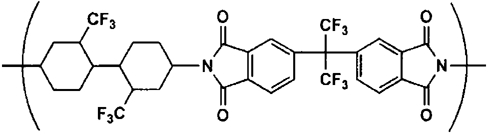
ポリイミドA(重量平均分子量:203000、イミド化率:100%)
100.0質量部
粒子:日本アエロジル(株)R812(一次粒径7nm) 0.1質量部
次いで、無端ベルト流延装置を用い、ドープを温度30℃、1500mm幅でステンレスベルト支持体上に均一に流延した。ステンレスベルトの温度は30℃に制御した。
ステンレスベルト支持体上で、流延(キャスト)したフィルム中の残留溶媒量が75%になるまで溶媒を蒸発させ、次いで剥離張力180N/mで、ステンレスベルト支持体上から剥離した。
剥離した残留溶媒率30質量%のウェブを、搬送ロールで、搬送張力100N/m、乾燥時間15分間として、残留溶媒量が0.1質量%未満となる乾燥温度で乾燥させ、乾燥膜厚25μmのフィルムを得た。得られたフィルムを巻き取った。
巻き取ったフィルムに対して、赤外線ヒーターにより300℃で5分間加熱処理を行い、ポリイミドフィルム1を得た。
ドープの調製において、主ドープの成分として準備したエタノールとは異なる純エタノールを、ドープ全量に対する添加量が10質量%となるようにドープに添加した以外は、実施例3と同様にしてポリアリレートフィルム13を得た。
ドープの調製において、主ドープを下記ドープに変更した以外は、実施例3と同様にしてポリアリレートフィルム14を得た。
ジクロロメタン 400質量部
ポリアリレート1 100質量部
粒子:日本アエロジル(株)R812(一次粒径7nm) 0.1質量部
(主ドープの組成)
ジクロロメタン 440質量部
エタノール 40質量部
セルローストリアセテート(酢化度61.0%、Mn=148000、Mw=310000、Mw/Mn=2.1)
100質量部
粒子:日本アエロジル(株)R812(一次粒径7nm) 0.1質量部
上述のようにして得られた各フィルム(実施例1~15および比較例1~2)について、以下の評価試験を行った。
得られた光学フィルムを、2枚の偏光板を直交(クロスニコル)状態にしたものの間に配置して、一方の偏光板側から光を当てて、他方の偏光板側から目視で観察し、輝点異物の個数(個/m2)を測定した。その際、光学フィルムの長さ100mの範囲で、幅方向中央部や端部等を複数箇所観察した。
各フィルムについて、下記の方法に従ってフィルムの内部ヘイズを測定した。まず、きれいに洗浄したスライドガラスを使用し、ガラス/グリセリン/フィルム/グリセリン/ガラスの順に重ね合わせた。グリセリンは気泡が入らないように注意しながら、一滴(0.05ml)滴下した。その後、内部ヘイズ測定装置(ヘイズメーター(濁度計)(型式:NDH 2000、日本電色(株)製))を用いて、光源は5V9Wハロゲン球、受光部はシリコンフォトセル(比視感度フィルター付き)、測定はJIS K-7136に準じて、内部ヘイズ(%)を測定した。
×:0.2以上 実害あり
△:0.15超~0.2未満 実害なし
○:0.1~0.15 良好
◎:0.1未満 優良
結果を表1に示す。
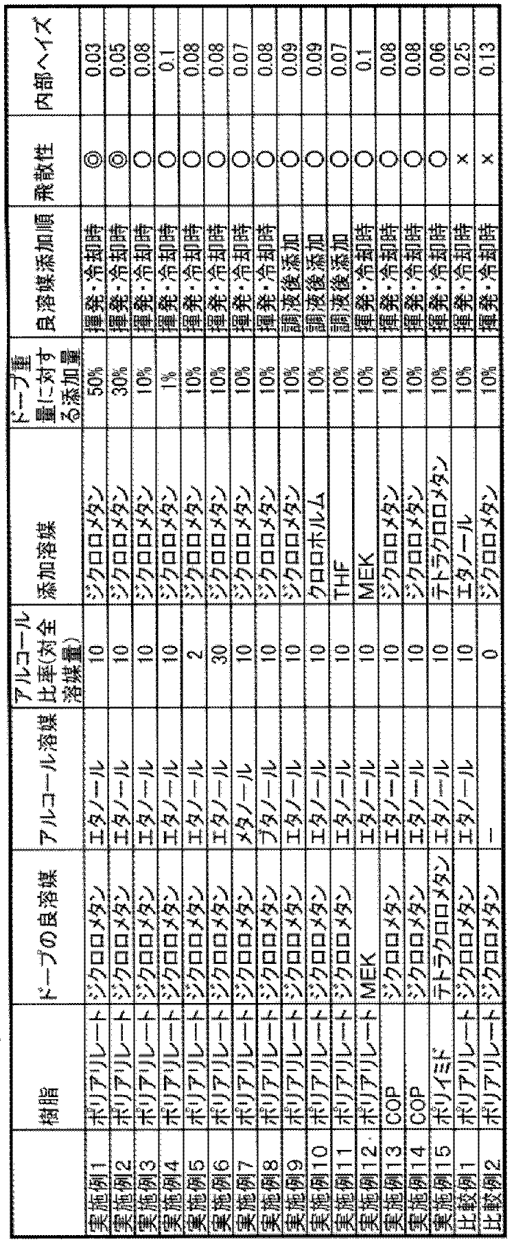
表1からわかるように、本発明の製造方法によって得られた実施例1~13においては、効率良くドープの不純物を除去でき、内部ヘイズの低い高品質な光学フィルムを製造できることが示された。
Claims (3)
- 溶液流延製膜法において、ポリイミド樹脂、ポリアリレート樹脂またはシクロオレフィン樹脂と、少なくとも1種類のアルコール溶媒と、前記樹脂に対する少なくとも1種類の良溶媒とを含むドープを調整し、支持体上に光学前記ドープを流延し、支持体上にウェブ(流延膜)を形成し、前記支持体からウェブを剥離し、その後剥離したウェブを巻き取り、乾燥することにより、光学フィルムを製造する方法において、
前記ドープを調整した後に、ドープへ良溶媒をさらに添加する工程と、その後、前記良溶媒を除去する工程を含む、光学フィルムの製造方法。 - 前記良溶媒がジクロロメタン又はテトラクロロメタンである、請求項1に記載の光学フィルムの製造方法。
- 添加する良溶媒量が、ドープ全量に対して1~50質量%である、請求項1または2に記載の光学フィルムの製造方法。
Priority Applications (3)
| Application Number | Priority Date | Filing Date | Title |
|---|---|---|---|
| JP2018544704A JP6889416B2 (ja) | 2016-10-12 | 2017-09-07 | 光学フィルムの製造方法 |
| CN201780062195.4A CN109804003A (zh) | 2016-10-12 | 2017-09-07 | 光学膜的制造方法 |
| KR1020197010100A KR102137345B1 (ko) | 2016-10-12 | 2017-09-07 | 광학 필름의 제조 방법 |
Applications Claiming Priority (2)
| Application Number | Priority Date | Filing Date | Title |
|---|---|---|---|
| JP2016-200596 | 2016-10-12 | ||
| JP2016200596 | 2016-10-12 |
Publications (1)
| Publication Number | Publication Date |
|---|---|
| WO2018070146A1 true WO2018070146A1 (ja) | 2018-04-19 |
Family
ID=61906192
Family Applications (1)
| Application Number | Title | Priority Date | Filing Date |
|---|---|---|---|
| PCT/JP2017/032198 Ceased WO2018070146A1 (ja) | 2016-10-12 | 2017-09-07 | 光学フィルムの製造方法 |
Country Status (4)
| Country | Link |
|---|---|
| JP (1) | JP6889416B2 (ja) |
| KR (1) | KR102137345B1 (ja) |
| CN (1) | CN109804003A (ja) |
| WO (1) | WO2018070146A1 (ja) |
Cited By (3)
| Publication number | Priority date | Publication date | Assignee | Title |
|---|---|---|---|---|
| WO2019207863A1 (ja) * | 2018-04-26 | 2019-10-31 | コニカミノルタ株式会社 | 光学フィルムの製造方法 |
| JP2020052138A (ja) * | 2018-09-25 | 2020-04-02 | 大日本印刷株式会社 | 位相差フィルムの製造方法、位相差フィルム、該位相差フィルムを用いた表示パネル及び画像表示装置 |
| WO2022045362A1 (ja) * | 2020-08-31 | 2022-03-03 | 住友化学株式会社 | フィルム |
Families Citing this family (5)
| Publication number | Priority date | Publication date | Assignee | Title |
|---|---|---|---|---|
| CN110327806A (zh) * | 2019-05-30 | 2019-10-15 | 浙江海轩科技有限公司 | 一种高分子膜的生产设备 |
| JP7326956B2 (ja) * | 2019-07-18 | 2023-08-16 | コニカミノルタ株式会社 | 光学フィルム製造方法 |
| WO2021199402A1 (ja) * | 2020-04-02 | 2021-10-07 | コニカミノルタ株式会社 | 積層フィルム、偏光板、表示装置及び偏光板ロールの製造方法 |
| CN116118079B (zh) * | 2023-03-02 | 2025-05-16 | 宜昌予信天诚新材料技术有限公司 | 一种聚酰亚胺薄膜胶态剥离装置 |
| CN121424584B (zh) * | 2026-01-04 | 2026-03-27 | 株洲时代华鑫新材料技术股份有限公司 | 一种聚酰亚胺薄膜化学流延设备、化学流延方法及亚胺化设备 |
Citations (5)
| Publication number | Priority date | Publication date | Assignee | Title |
|---|---|---|---|---|
| JP2006247894A (ja) * | 2005-03-08 | 2006-09-21 | Fuji Photo Film Co Ltd | ガスバリアフィルム、並びに、これを用いた有機エレクトロルミネッセンス素子および画像表示素子 |
| JP2014177089A (ja) * | 2013-03-15 | 2014-09-25 | Fujifilm Corp | フィルムおよびフィルムの製造方法 |
| JP2016014869A (ja) * | 2014-06-13 | 2016-01-28 | コニカミノルタ株式会社 | 環状ポリオレフィンフィルムの製造方法及び環状ポリオレフィンフィルム |
| JP2016075894A (ja) * | 2014-10-02 | 2016-05-12 | コニカミノルタ株式会社 | 光学フィルム、その製造方法、フレキシブルプリント基板及びled照明 |
| WO2016152459A1 (ja) * | 2015-03-24 | 2016-09-29 | コニカミノルタ株式会社 | ポリイミド系光学フィルム、その製造方法及び有機エレクトロルミネッセンスディスプレイ |
Family Cites Families (6)
| Publication number | Priority date | Publication date | Assignee | Title |
|---|---|---|---|---|
| JPS5140089A (ja) | 1974-09-30 | 1976-04-03 | Toyoda Chuo Kenkyusho Kk | Choonpahenkanki |
| JP5185555B2 (ja) | 2006-03-30 | 2013-04-17 | 富士フイルム株式会社 | 固体電解質フィルムの製造方法及び製造設備 |
| WO2007125729A1 (ja) * | 2006-04-28 | 2007-11-08 | Konica Minolta Opto, Inc. | 光学フィルムの製造方法 |
| JP4959597B2 (ja) | 2007-04-26 | 2012-06-27 | 富士フイルム株式会社 | 固体電解質フィルムの製造方法 |
| WO2012056671A1 (ja) | 2010-10-26 | 2012-05-03 | コニカミノルタオプト株式会社 | セルロースエステル含有樹脂成形物の製造方法、光学フィルム、偏光板、及び表示装置 |
| JP5648494B2 (ja) * | 2011-01-25 | 2015-01-07 | 住友化学株式会社 | 粘着剤シート、粘着剤付き光学フィルム及び光学積層体 |
-
2017
- 2017-09-07 JP JP2018544704A patent/JP6889416B2/ja active Active
- 2017-09-07 CN CN201780062195.4A patent/CN109804003A/zh active Pending
- 2017-09-07 WO PCT/JP2017/032198 patent/WO2018070146A1/ja not_active Ceased
- 2017-09-07 KR KR1020197010100A patent/KR102137345B1/ko active Active
Patent Citations (5)
| Publication number | Priority date | Publication date | Assignee | Title |
|---|---|---|---|---|
| JP2006247894A (ja) * | 2005-03-08 | 2006-09-21 | Fuji Photo Film Co Ltd | ガスバリアフィルム、並びに、これを用いた有機エレクトロルミネッセンス素子および画像表示素子 |
| JP2014177089A (ja) * | 2013-03-15 | 2014-09-25 | Fujifilm Corp | フィルムおよびフィルムの製造方法 |
| JP2016014869A (ja) * | 2014-06-13 | 2016-01-28 | コニカミノルタ株式会社 | 環状ポリオレフィンフィルムの製造方法及び環状ポリオレフィンフィルム |
| JP2016075894A (ja) * | 2014-10-02 | 2016-05-12 | コニカミノルタ株式会社 | 光学フィルム、その製造方法、フレキシブルプリント基板及びled照明 |
| WO2016152459A1 (ja) * | 2015-03-24 | 2016-09-29 | コニカミノルタ株式会社 | ポリイミド系光学フィルム、その製造方法及び有機エレクトロルミネッセンスディスプレイ |
Cited By (6)
| Publication number | Priority date | Publication date | Assignee | Title |
|---|---|---|---|---|
| WO2019207863A1 (ja) * | 2018-04-26 | 2019-10-31 | コニカミノルタ株式会社 | 光学フィルムの製造方法 |
| JPWO2019207863A1 (ja) * | 2018-04-26 | 2021-04-30 | コニカミノルタ株式会社 | 光学フィルムの製造方法 |
| JP7063380B2 (ja) | 2018-04-26 | 2022-05-09 | コニカミノルタ株式会社 | 光学フィルムの製造方法 |
| JP2020052138A (ja) * | 2018-09-25 | 2020-04-02 | 大日本印刷株式会社 | 位相差フィルムの製造方法、位相差フィルム、該位相差フィルムを用いた表示パネル及び画像表示装置 |
| JP7434704B2 (ja) | 2018-09-25 | 2024-02-21 | 大日本印刷株式会社 | 位相差フィルムの製造方法、位相差フィルム、該位相差フィルムを用いた表示パネル及び画像表示装置 |
| WO2022045362A1 (ja) * | 2020-08-31 | 2022-03-03 | 住友化学株式会社 | フィルム |
Also Published As
| Publication number | Publication date |
|---|---|
| KR20190052049A (ko) | 2019-05-15 |
| JPWO2018070146A1 (ja) | 2019-07-25 |
| JP6889416B2 (ja) | 2021-06-18 |
| KR102137345B1 (ko) | 2020-07-23 |
| CN109804003A (zh) | 2019-05-24 |
Similar Documents
| Publication | Publication Date | Title |
|---|---|---|
| JP6889416B2 (ja) | 光学フィルムの製造方法 | |
| TWI734782B (zh) | 聚乙烯醇系薄膜及其製造方法與利用此聚乙烯醇系薄膜之偏光膜 | |
| TWI529200B (zh) | 聚醯胺醯亞胺溶液及聚醯胺醯亞胺膜 | |
| CN109416424B (zh) | 偏光膜用聚乙烯醇系薄膜和其制造方法、以及使用该偏光膜用聚乙烯醇系薄膜的偏光膜 | |
| CN105392839B (zh) | 双轴拉伸聚酯薄膜及其制造方法、以及光学片 | |
| CN105367969B (zh) | 光学膜及其制造方法、偏振片保护膜、偏振片以及液晶显示装置 | |
| CN108139526B (zh) | 聚乙烯醇系薄膜、及使用其的偏光膜、偏光板、以及聚乙烯醇系薄膜的制造方法 | |
| JP6953804B2 (ja) | ポリビニルアルコール系フィルム、およびその製造方法、ならびに偏光膜 | |
| JP3913613B2 (ja) | 溶液製膜方法、セルロースエステルフィルム、保護フィルム、および偏光板 | |
| CN102325642B (zh) | 光学膜的制造方法 | |
| CN116368410A (zh) | 偏光膜制造用聚乙烯醇系薄膜、偏光膜制造用聚乙烯醇系薄膜的制造方法、偏光膜 | |
| JP2017040727A (ja) | 光学フィルム及び光学フィルムの製造方法 | |
| JP6143369B2 (ja) | 樹脂組成物、フィルム、偏光板保護フィルム、偏光板及び液晶表示装置、ビス型脂環カルドフェノール化合物 | |
| JP2018065259A (ja) | 光学フィルムの製造方法 | |
| JP2004106420A (ja) | セルロースエステルフイルム及びその製造方法 | |
| JP2010082992A (ja) | 位相差フィルムの製造方法 | |
| TW201730278A (zh) | 光學薄膜之製造方法 | |
| CN106164165A (zh) | (甲基)丙烯酸系树脂组合物、薄膜、偏振片保护膜、偏振片及液晶显示装置 | |
| JP4049382B2 (ja) | 位相差フィルムの製造方法 | |
| TWI480148B (zh) | A method for producing a resin film, a casting die, a manufacturing apparatus for a resin film, a resin film, a polarizing plate, and a liquid crystal display device | |
| JP2016193520A (ja) | 透明積層フィルムおよびその製造方法 | |
| KR20200130448A (ko) | 광학 필름의 제조 방법 | |
| JP2024002560A (ja) | 位相差フィルムの製造方法 | |
| JP2017223941A (ja) | 偏光膜用ポリビニルアルコール系フィルム、およびその製造方法、ならびに偏光膜 | |
| JP2018154036A (ja) | ディスプレイ装置用加飾フィルム |
Legal Events
| Date | Code | Title | Description |
|---|---|---|---|
| 121 | Ep: the epo has been informed by wipo that ep was designated in this application |
Ref document number: 17861144 Country of ref document: EP Kind code of ref document: A1 |
|
| ENP | Entry into the national phase |
Ref document number: 2018544704 Country of ref document: JP Kind code of ref document: A |
|
| ENP | Entry into the national phase |
Ref document number: 20197010100 Country of ref document: KR Kind code of ref document: A |
|
| NENP | Non-entry into the national phase |
Ref country code: DE |
|
| 122 | Ep: pct application non-entry in european phase |
Ref document number: 17861144 Country of ref document: EP Kind code of ref document: A1 |