WO2018066166A1 - 加工条件決定装置及び切削工具選択装置 - Google Patents
加工条件決定装置及び切削工具選択装置 Download PDFInfo
- Publication number
- WO2018066166A1 WO2018066166A1 PCT/JP2017/019321 JP2017019321W WO2018066166A1 WO 2018066166 A1 WO2018066166 A1 WO 2018066166A1 JP 2017019321 W JP2017019321 W JP 2017019321W WO 2018066166 A1 WO2018066166 A1 WO 2018066166A1
- Authority
- WO
- WIPO (PCT)
- Prior art keywords
- cutting
- tool
- unit
- drive motor
- output value
- Prior art date
- Legal status (The legal status is an assumption and is not a legal conclusion. Google has not performed a legal analysis and makes no representation as to the accuracy of the status listed.)
- Ceased
Links
Images




Classifications
-
- B—PERFORMING OPERATIONS; TRANSPORTING
- B23—MACHINE TOOLS; METAL-WORKING NOT OTHERWISE PROVIDED FOR
- B23Q—DETAILS, COMPONENTS, OR ACCESSORIES FOR MACHINE TOOLS, e.g. ARRANGEMENTS FOR COPYING OR CONTROLLING; MACHINE TOOLS IN GENERAL CHARACTERISED BY THE CONSTRUCTION OF PARTICULAR DETAILS OR COMPONENTS; COMBINATIONS OR ASSOCIATIONS OF METAL-WORKING MACHINES, NOT DIRECTED TO A PARTICULAR RESULT
- B23Q15/00—Automatic control or regulation of feed movement, cutting velocity or position of tool or work
- B23Q15/20—Automatic control or regulation of feed movement, cutting velocity or position of tool or work before or after the tool acts upon the workpiece
-
- B—PERFORMING OPERATIONS; TRANSPORTING
- B23—MACHINE TOOLS; METAL-WORKING NOT OTHERWISE PROVIDED FOR
- B23Q—DETAILS, COMPONENTS, OR ACCESSORIES FOR MACHINE TOOLS, e.g. ARRANGEMENTS FOR COPYING OR CONTROLLING; MACHINE TOOLS IN GENERAL CHARACTERISED BY THE CONSTRUCTION OF PARTICULAR DETAILS OR COMPONENTS; COMBINATIONS OR ASSOCIATIONS OF METAL-WORKING MACHINES, NOT DIRECTED TO A PARTICULAR RESULT
- B23Q15/00—Automatic control or regulation of feed movement, cutting velocity or position of tool or work
-
- G—PHYSICS
- G05—CONTROLLING; REGULATING
- G05B—CONTROL OR REGULATING SYSTEMS IN GENERAL; FUNCTIONAL ELEMENTS OF SUCH SYSTEMS; MONITORING OR TESTING ARRANGEMENTS FOR SUCH SYSTEMS OR ELEMENTS
- G05B19/00—Program-control systems
- G05B19/02—Program-control systems electric
- G05B19/18—Numerical control [NC], i.e. automatically operating machines, in particular machine tools, e.g. in a manufacturing environment, so as to execute positioning, movement or co-ordinated operations by means of program data in numerical form
-
- G—PHYSICS
- G05—CONTROLLING; REGULATING
- G05B—CONTROL OR REGULATING SYSTEMS IN GENERAL; FUNCTIONAL ELEMENTS OF SUCH SYSTEMS; MONITORING OR TESTING ARRANGEMENTS FOR SUCH SYSTEMS OR ELEMENTS
- G05B19/00—Program-control systems
- G05B19/02—Program-control systems electric
- G05B19/18—Numerical control [NC], i.e. automatically operating machines, in particular machine tools, e.g. in a manufacturing environment, so as to execute positioning, movement or co-ordinated operations by means of program data in numerical form
- G05B19/416—Numerical control [NC], i.e. automatically operating machines, in particular machine tools, e.g. in a manufacturing environment, so as to execute positioning, movement or co-ordinated operations by means of program data in numerical form characterised by control of velocity, acceleration or deceleration
- G05B19/4163—Adaptive control of feed or cutting velocity
-
- G—PHYSICS
- G05—CONTROLLING; REGULATING
- G05B—CONTROL OR REGULATING SYSTEMS IN GENERAL; FUNCTIONAL ELEMENTS OF SUCH SYSTEMS; MONITORING OR TESTING ARRANGEMENTS FOR SUCH SYSTEMS OR ELEMENTS
- G05B2219/00—Program-control systems
- G05B2219/30—Nc systems
- G05B2219/37—Measurements
-
- G—PHYSICS
- G05—CONTROLLING; REGULATING
- G05B—CONTROL OR REGULATING SYSTEMS IN GENERAL; FUNCTIONAL ELEMENTS OF SUCH SYSTEMS; MONITORING OR TESTING ARRANGEMENTS FOR SUCH SYSTEMS OR ELEMENTS
- G05B2219/00—Program-control systems
- G05B2219/30—Nc systems
- G05B2219/49—Nc machine tool, till multiple
- G05B2219/49074—Control cutting speed
Definitions
- the present invention relates to a machining condition determination device that determines a machining condition of a cutting tool used in a machine tool, and a cutting tool selection device that selects a cutting tool to be used in a machine tool that performs machining using a plurality of cutting tools.
- Taylor's equation that defines the relationship between the cutting speed (peripheral speed) of a cutting tool and the life of the cutting tool is known (see, for example, Patent Document 1).
- the life of the cutting tool has been calculated using such a calculation formula.
- the present invention has been made in view of the above circumstances, and a machining condition determination device capable of determining machining conditions capable of improving cutting efficiency without shortening the tool life and shortening the tool life. It is an object of the present invention to provide a cutting tool selection device that can select a cutting tool that can improve the cutting efficiency.
- the processing condition determination device is a processing condition determination device that determines a processing condition of a cutting tool used in a machine tool, A first setting unit for setting a cutting speed of the cutting tool; A storage unit that stores a maximum output value of a drive motor that rotates a shaft that holds the cutting tool, and a rotation speed of the drive motor corresponding to the maximum output value; A rotation speed determination unit that acquires a steady value of the maximum output value of the drive motor stored in the storage unit and determines the rotation speed of the drive motor corresponding to the acquired steady value of the maximum output value; A tool diameter determination unit that calculates a tool diameter of the cutting tool from the cutting speed set by the first setting unit and the rotation speed of the drive motor determined by the rotation number determination unit. .
- the above-mentioned axis means a spindle that rotates while holding a tool.
- a tool spindle in a machining center a similar tool spindle in a composite lathe, or a tool disposed on a turret in a lathe.
- Main spindles also called milling axes are included.
- Vc the cutting speed
- D the tool diameter
- n the rotation speed of the drive motor
- machining condition determination device In the machining condition determination device according to the present invention, data on the correspondence relationship between the maximum output value of the drive motor that rotates the cutting tool and the rotation speed of the drive motor corresponding to the maximum output value is stored in the storage unit in advance.
- the maximum output value of the drive motor increases until reaching a certain number of revolutions, and becomes a steady value when the number exceeds the certain number of revolutions.
- the cutting speed of the cutting tool is input by the user, the cutting speed is set by the first setting unit. Moreover, the steady value of the maximum output value of the drive motor memorize
- the rotation speed determination unit can determine the minimum value corresponding to the steady value as the rotation speed of the drive motor as the rotation speed of the drive motor corresponding to the steady value of the acquired maximum output value, and The maximum value corresponding to the steady value can also be determined as the rotational speed of the drive motor. Further, the rotation speed determination unit can determine the rotation speed between the minimum value and the maximum value corresponding to the steady value as the rotation speed of the drive motor.
- the rotational speed determination unit sets the minimum value corresponding to the steady value to the value of the drive motor. It can be determined as the number of revolutions.
- the tool diameter may be made as small as possible. Can be determined as the rotational speed of the drive motor. That is, in the present invention, either when the rotational speed determination unit determines the rotational speed of the drive motor to the minimum value corresponding to the steady value or when the rotational speed is determined to the maximum value corresponding to the steady value. Even if it exists, it contributes to the improvement of cutting efficiency.
- the rotation speed of the drive motor is determined by the tool diameter determination unit while maintaining the cutting speed set by the user (that is, the state in which the cutting speed is not increased). It is possible to calculate the tool diameter according to the above, that is, the tool diameter as a machining condition that can improve the cutting efficiency. Therefore, if machining is performed using a cutting tool having the calculated tool diameter in a machine tool, cutting efficiency can be improved without shortening the tool life of the cutting tool.
- the processing condition determination device includes a cutting depth a p , a cutting width a e , a maximum feed amount f z determined based on a cutting edge shape of the cutting tool, and the rotation speed determination unit.
- the rotation number n of the drive motor determined by the above, the number z of blades of the cutting tool, the specific cutting resistance k c acquired in advance based on the tool diameter, and the mechanical efficiency ⁇ acquired in advance are set as initial values, respectively.
- P c a p ⁇ a e ⁇ f z ⁇ n ⁇ z ⁇ k c / (60 ⁇ 10 6 ⁇ ⁇ )
- the cutting depth a p , the cutting width a e , the maximum feed amount f z per tooth, the rotational speed of the drive motor determined by the rotational speed determination unit The initial values of n, the number z of cutting tools, the specific cutting resistance k c , and the mechanical efficiency ⁇ are set by the second setting unit.
- the motor output value calculation unit calculates the output value of the drive motor from the above equation.
- the load ratio calculation unit calculates a load ratio that is a ratio between the calculated output value and the steady value of the maximum output value stored in the storage unit.
- the calculated load ratio is displayed on the display unit. Thereby, the user can recognize the load ratio in the case where the cutting tool having the tool diameter calculated by the tool diameter determining unit is employed under each of the initial values.
- the processing condition determining device, said output value, and the ratio cutting force, from said mechanical efficiency further comprising a cutting efficiency calculation unit for calculating a cutting efficiency C e of the following formula, wherein the display unit, It may be configured to display the cutting efficiency.
- C e a p ⁇ a e ⁇ f z ⁇ n ⁇ z
- the cutting efficiency is calculated from the output value, the specific cutting resistance, and the mechanical efficiency by the cutting efficiency calculation unit.
- the calculated cutting efficiency is displayed on the display unit. Thereby, the user can recognize the cutting efficiency under each of the initial values.
- the machining condition determination device includes a third setting unit that changes and sets the load ratio to a desired value, and the motor output value calculation unit recalculates the output value based on the changed load ratio.
- the machining condition determination device is configured so that, based on the recalculated output value, at least one of main machining conditions including the cutting depth, the cutting width, and the feed amount per blade.
- the cutting efficiency calculating unit is configured to recalculate the cutting efficiency based on the recalculated output value and the value changed by the condition changing unit.
- the display unit includes first information composed of the recalculated cutting efficiency, and second information composed of the main machining condition changed by the condition changing unit and the main machining condition not changed. At least one emotion It may be configured to display.
- the load ratio is set by the third setting unit.
- the user when the displayed load ratio has a margin with respect to the upper limit value, the user can set a load ratio higher than the displayed load ratio, and conversely, the displayed load ratio is the upper limit. If there is no room for the value, the user can set a load ratio lower than the displayed load ratio.
- the output value of the drive motor is recalculated by the motor output value calculation unit.
- the cutting efficiency calculating unit recalculates the cutting efficiency. At least one of the first information including the recalculated cutting efficiency and the second information including the main machining conditions changed by the condition changing unit and the main machining conditions not changed is displayed on the display unit.
- the cutting efficiency is recalculated by the cutting efficiency calculation unit. In such a configuration, the user can recognize the cutting efficiency and main machining conditions when the load ratio is changed to a desired value by visually recognizing the display unit.
- the machining condition determination device further includes a fourth setting unit that changes and sets at least one of main cutting conditions including the cutting depth, the cutting width, and the feed amount per blade, and the cutting efficiency
- the calculation unit is configured to recalculate the cutting efficiency based on the value changed and set by the fourth setting unit
- the load ratio calculation unit is configured to recalculate the load ratio based on the recalculated cutting efficiency.
- the display unit may be configured to display at least one of the recalculated cutting efficiency and the recalculated load ratio.
- At least one of the main machining conditions is changed and set by the fourth setting unit based on a user input operation.
- the cutting efficiency calculation unit is configured to recalculate the cutting efficiency.
- the load ratio is recalculated by the load ratio calculation unit based on the recalculated cutting efficiency.
- the machining condition determination device further includes a fifth setting unit that changes and sets at least one of the cutting depth, the cutting width, and the feed amount per blade while maintaining the load ratio.
- the cutting efficiency calculating unit is configured to recalculate the cutting efficiency based on the value changed and set by the fifth setting unit, and the display unit displays the recalculated cutting efficiency. It may be configured.
- At least one of the main machining conditions is changed and set by the fifth setting unit while maintaining the load ratio (that is, without changing the load ratio).
- the cutting efficiency calculation unit is configured to recalculate the cutting efficiency.
- the cutting tool selection device is a cutting tool selection device that selects the cutting tool to be used in a machine tool that performs processing using a plurality of cutting tools,
- a setting unit for setting a cutting speed of the cutting tool;
- a first storage unit that stores a maximum output value of a drive motor that rotates a shaft that holds the cutting tool, and a rotation speed of the drive motor corresponding to the maximum output value;
- a rotation speed determination unit that acquires a steady value of the maximum output value of the drive motor stored in the first storage unit and determines a rotation speed of the drive motor corresponding to the acquired steady value of the maximum output value;
- a tool diameter determining unit that calculates a tool diameter of the cutting tool from the cutting speed set by the setting unit and the rotational speed of the drive motor determined by the rotational speed determining unit;
- a second storage unit for storing in advance the tool diameter of each of the plurality of cutting tools; The tool diameter calculated by the tool diameter determination unit is compared with the tool diameter stored in the second storage unit, and when the tool
- the relationship between the maximum output value of the drive motor that rotates the cutting tool and the rotational speed of the drive motor corresponding to the maximum output value is stored in advance in the first storage unit.
- the cutting speed of the cutting tool is input by the user, the cutting speed is set by the setting unit. Moreover, the steady value of the maximum output value of the drive motor memorize
- the rotational speed determination unit sets the minimum value corresponding to the steady value to the drive motor.
- the number of rotations can be determined.
- the tool diameter may be made as small as possible.
- the tool diameter of each of the plurality of cutting tools is stored in advance in the second storage unit.
- the tool selection unit compares the tool diameter calculated by the tool diameter determination unit and the tool diameter stored in the second storage unit, and if the tool diameters match, the cutting tool having the tool diameter is selected. The On the other hand, if the tool diameters do not match in the above comparison, a cutting tool having a tool diameter closest to the tool diameter calculated by the tool diameter determination unit is selected by the tool selection unit.
- the tool diameter according to the rotational speed of the drive motor that is, the cutting efficiency, by the tool diameter determination unit while maintaining the cutting speed set by the user.
- the tool selection unit selects a cutting tool having the same tool diameter or a cutting tool having a tool diameter closest to the tool diameter. Therefore, if the cutting tool selected by the tool selection unit is used in the machine tool, the cutting efficiency can be improved without shortening the tool life of the cutting tool.
- a machining condition determination device capable of determining machining conditions that can improve cutting efficiency without shortening the tool life, and cutting efficiency without shortening the tool life.
- a cutting tool selection device capable of selecting a cutting tool that can be improved can be provided.
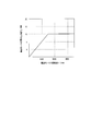
- 2 is a graph showing the maximum output value of the drive motor stored in the storage unit of FIG. 1 and the rotational speed of the drive motor corresponding to the maximum output value.
- the machining condition determining apparatus 1 includes a first to fifth setting unit 2a, 2b, 2c, 2d, 2e, a storage unit 3 composed of various memories, and a rotational speed determination. 4, a tool diameter determining unit 5, a motor output value calculating unit 6, a load ratio calculating unit 7, a display unit 8, a cutting efficiency calculating unit 9, and a condition changing unit 10.
- the arithmetic device 1a configured by the unit 7, the cutting efficiency calculating unit 9, and the condition changing unit 10 may be incorporated in an NC (Numerical Control) device, or the arithmetic device 1a communicates with the NC device.
- NC Genetic Control
- the said display part 8 is comprised by the touch panel of an operation panel, for example, you may combine a display part, a keyboard, etc. not only with a display part which has such an input function.
- the changing unit 10 is functionally realized by a CPU provided in the machining condition determining apparatus 1 executing a predetermined program stored in a memory.
- the first to fifth setting units 2a, 2b, 2c, 2d, and 2e are included in the setting unit 2.
- the processing condition determination device 1 of the present embodiment if the user sets a desired cutting speed, the processing with the cutting tool is performed at the set cutting speed without shortening the tool life of the cutting tool.
- the tool diameter that can improve the cutting efficiency can be calculated. This will be described in detail below.
- the user operates a key (not shown) on the input unit 8c (see FIG. 3) displayed on the display unit 8 under the control of the setting unit 2 to input a desired cutting speed.
- the input method is the same below.
- the setting information is stored in the storage unit 3 by the first setting unit 2a.
- the storage unit 3 stores in advance the maximum output value of the drive motor that rotates the spindle that holds the cutting tool in the machine tool and the rotation speed of the drive motor corresponding to the maximum output value.
- the rotation speed determination unit 4 acquires a steady value of the maximum output value of the drive motor stored in the storage unit 3. Specifically, as shown in FIG. 2, the maximum output value of the drive motor continues to rise until reaching a certain rotational speed, and becomes a steady value when the rotational speed exceeds the certain rotational speed. For example, in FIG. 2, the steady value of the maximum output value is 12 kW.
- the rotation speed determination unit 4 determines the rotation speed of the drive motor corresponding to the above steady value of the acquired maximum output value.
- the rotational speed determination unit 4 drives the minimum value among the rotational speeds corresponding to the steady value from the viewpoint of increasing the tool diameter as much as possible and improving the cutting efficiency by processing with fewer passes. Determined as the motor speed.
- the user may recognize a load ratio (%) that is a ratio between the output value of the drive motor and the steady value of the maximum output value stored in the storage unit 3 by setting predetermined processing conditions. It can. This will be described in detail below.
- the load ratio may be referred to as a spindle load.
- the user can input the cutting depth a p with the cutting tool, the cutting width a e with the cutting tool, the cutting tool with respect to the input unit 8 e displayed on the display unit 8 under the control of the setting unit 2.
- the maximum value f z per blade feeding amount determined based on the edge shape, the rotational speed n of the drive motor, the number of blades z of the cutting tool, the specific cutting force k c that are obtained in advance, and mechanical efficiency ⁇ previously acquired
- Each initial value of is input.
- Each set initial value is stored in the storage unit 3 by the second setting unit 2b.
- the rotation speed determined by the rotation speed determination part 4 may be automatically input into the predetermined location of the input part 8e.
- the motor output value calculation unit 6 calculates the output value Pc of the drive motor by the following equation.
- the calculated output value is stored in the storage unit 3 and displayed in the display area 8a (see FIG. 3) of the display unit 8. Thereby, the user can visually recognize the output value of the drive motor.
- P c a p ⁇ a e ⁇ f z ⁇ n ⁇ z ⁇ k c / (60 ⁇ 10 6 ⁇ ⁇ )
- the mechanical efficiency is acquired in advance by actual cutting.
- the specific cutting resistance is acquired in advance by the following equation.
- k c k c1 ⁇ h m -mc ⁇ (1- ⁇ 0/100)
- k c1 is the ratio cutting resistance when the chip thickness is 1 mm
- m c is a coefficient when the specific cutting resistance varies by chip thickness
- gamma 0 is the rake angle of the tool
- h m Is the average chip thickness and is obtained by the following equation.
- h m 360 ⁇ sin k r ⁇ a e ⁇ f z / ( ⁇ ⁇ D ⁇ acos (1-2 ⁇ a e / D))
- ⁇ r is a cutting edge angle.
- the load ratio calculation unit 7 (see FIG. 1) is connected to the output value of the drive motor and the drive motor stored in the storage unit 3.
- the load ratio which is the ratio of the maximum output value to the steady value, is calculated.
- the calculated load ratio is displayed in the display area 8a (see FIG. 3) of the display unit 8. Thereby, the user can visually recognize the load ratio.
- the cutting efficiency calculation unit 9 calculates the output value of the drive motor, the specific cutting resistance, and the mechanical efficiency obtained as described above. From the above, the cutting efficiency is calculated by the following formula.
- the calculated cutting efficiency is displayed in the display area 8a (see FIG. 3) of the display unit 8. Thereby, the user can visually recognize the cutting efficiency.
- C e a p ⁇ a e ⁇ f z ⁇ n ⁇ z
- the user can input a desired load ratio to the input unit 8d (see FIG. 3) displayed on the display unit 8 under the control of the setting unit 2.
- the user can set a desired load ratio higher than the load ratio after visually recognizing and displaying the load ratio calculated and displayed by the load ratio calculation unit 7.
- a low desired load ratio can also be set.
- the changed load ratio is stored in the storage unit 3 by the third setting unit 2c.
- the motor output value calculation unit 6 (see FIG. 1) recalculates the output value of the drive motor based on the changed load ratio.
- the recalculated output value of the drive motor is stored in the storage unit 3 and displayed in the display area 8 a of the display unit 8. Thereby, the user can visually recognize the recalculated output value of the drive motor.
- the cutting efficiency calculating unit 9 Based on the recalculated output value of the drive motor and the value changed by the condition changing unit 10, the cutting efficiency calculating unit 9 (see FIG. 1) recalculates the cutting efficiency.
- the recalculated cutting efficiency is displayed in the display area 8 a of the display unit 8. Thereby, the user can visually recognize the recalculated cutting efficiency.
- the user inputs at least one of the main machining conditions (that is, the cutting depth, the cutting width, and the feed amount per blade) with respect to the input unit 8e.
- a desired value can be entered.
- the user may change and set at least one of the main machining conditions to a high value (that is, a value higher than the current value). it can.
- the user can set the value of the main machining condition to a high value on the basis of the value of the main machining condition displayed in the display area 8b of the display unit 8.
- the value of the main machining conditions changed by the user is stored in the storage unit 3 by the fourth setting unit 2d.
- the cutting efficiency calculation unit 9 recalculates the cutting efficiency based on the values of the main machining conditions changed by the user and the main machining conditions not changed.
- the load ratio calculation unit 7 recalculates the load ratio based on the recalculated cutting efficiency.
- the recalculated cutting efficiency and load ratio are displayed in the display area 8a of the display unit 8 (see FIG. 3). Thereby, the user can visually recognize the cutting efficiency and the load ratio recalculated based on the main machining conditions changed by the user.
- a plurality of cutting efficiency can be obtained by variously changing the main machining conditions, and the user can determine an appropriate one of them.
- the user presses the maintenance button 11 displayed on the left side of the “load ratio” in the display area 8 a of the display unit 8 to display the display area 8 a of the display unit 8.
- the load ratio can be maintained (that is, fixed).
- the load ratio to be maintained may be a load ratio calculated after an input to the input unit 8e by the user, or may be a load ratio changed and set to a desired value by an input to the input unit 8d by the user. Good.
- the user can input at least one desired value among the main machining conditions (that is, the cutting depth, the cutting width, and the feed amount per tooth) to the input unit 8e.
- the value of the main machining conditions changed by the user is stored in the storage unit 3 by the fifth setting unit 2e.
- the cutting efficiency calculation unit 9 recalculates the cutting efficiency based on the changed and set value while maintaining the load ratio.
- the recalculated cutting efficiency is displayed in the display area 8 a of the display unit 8. Thereby, the user can visually recognize the cutting efficiency recalculated based on the main machining conditions changed by the user while maintaining the load ratio.
- a plurality of cutting efficiency can be obtained while maintaining the load ratio, and the user can determine an appropriate cutting efficiency from among them.
- the tool diameter determination unit 5 drives the tool while the cutting speed set by the user is maintained (that is, the cutting speed is not increased).
- the tool diameter corresponding to the rotation speed of the motor that is, the tool diameter as a machining condition that can improve the cutting efficiency can be calculated. Therefore, if machining is performed using a cutting tool having the above-mentioned tool diameter in a machine tool, cutting efficiency can be improved without shortening the tool life of the cutting tool.
- the output value of the drive motor is calculated by the motor output value calculation unit 6 based on the respective initial values set by the second setting unit 2b. Then, the load ratio calculation unit 7 calculates the load ratio. Thereby, the user can easily recognize the load ratio when the cutting tool having the tool diameter calculated by the tool diameter determining unit 5 is employed under the above initial values.
- the cutting efficiency is calculated by the cutting efficiency calculation unit 9. Thereby, the user can easily recognize the cutting efficiency under each of the initial values.
- the user can change and set the load ratio to a desired value after recognizing the load ratio displayed in the display area 8a of the display unit 8.
- the main machining conditions are automatically changed by the condition changing unit 10 accordingly, and the cutting efficiency after the change of the main machining conditions is calculated as the cutting efficiency.
- the user can recognize the cutting efficiency and main machining conditions when the load ratio is changed to a desired value.
- the user can change and set at least one of the main machining conditions after recognizing the displayed cutting efficiency. Then, the cutting efficiency is recalculated by the cutting efficiency calculator 9 based on the changed main machining conditions. Based on the recalculated cutting efficiency, the load ratio calculation unit 7 recalculates the load ratio. With such a configuration, the user can determine any one of the obtained cutting efficiency and load ratio by variously changing the main machining conditions.
- At least one of the main machining conditions can be changed and set while the load ratio is maintained (that is, the load ratio is not changed).
- the cutting efficiency is recalculated by the cutting efficiency calculator 9 based on the changed main machining conditions.
- the cutting tool selection apparatus selects an appropriate cutting tool to be used in a machine tool that performs processing using a plurality of cutting tools.
- the cutting tool selection device 50 of the present embodiment includes a rotation speed determination unit 4, a tool diameter determination unit 5, a display unit 8, a setting unit 51, a first storage unit 52, a second storage unit 53, And a tool selection unit 54.
- the calculation device 50a including the rotation speed determination unit 4, the tool diameter determination unit 5, the setting unit 51, the first storage unit 52, the second storage unit 53, and the tool selection unit 54 is an NC device.
- the arithmetic device 50a may be applied as an external device that communicates with the NC device.
- the rotation speed determination unit 4, the tool diameter determination unit 5, and the display unit 8 are the same as those of the machining condition determination device 1 in FIG.
- the setting unit 51 and the tool selection unit 54 are functionally realized by a CPU provided in the cutting tool selection device 50 executing a predetermined program stored in a memory.
- the cutting tool selection device 50 of the present embodiment if a cutting speed desired by the user is set, the tool life of the cutting tool is reduced when machining with the cutting tool is performed at the set cutting speed in the machine tool.
- a cutting tool having a tool diameter capable of improving the cutting efficiency can be selected without shortening. This will be described in detail below.
- the second storage unit 53 stores in advance the tool diameter of each of the plurality of cutting tools.
- the plurality of cutting tools may be a plurality of cutting tools stored in a tool magazine provided in the machine tool, or may be a plurality of cutting tools stored outside the machine tool (for example, a warehouse). Good.
- the tool number, tool diameter, tool length, tool type (tool type), and later evaluation stored in the second storage unit 53 are displayed on the display unit 8. It is displayed in the area 8c.
- the user inputs a desired cutting speed to the input unit 8 c displayed on the display unit 8 under the control of the setting unit 51.
- the cutting speed setting information is stored in the first storage unit 52 by the setting unit 51.
- the rotational speed determination unit 4 determines the rotational speed of the drive motor
- the tool diameter determination unit 5 calculates the tool diameter of the cutting tool to be used in the machine tool under the set cutting speed. This is the same as the condition determining apparatus 1.
- the tool diameter calculated by the tool diameter determining unit 5 is displayed in the display area 8 a of the display unit 8. Thereby, the user can visually recognize the calculated tool diameter.
- the tool selection unit 54 compares the tool diameter calculated by the tool diameter determination unit 5 with the tool diameter stored in the second storage unit 53. For example, it is assumed that the tool diameter calculated by the tool diameter determining unit 5 is 63.0 mm. In this case, since there is a tool diameter stored in the second storage unit 53 that matches the calculated tool diameter, the tool selection unit 54 selects the matched tool diameter. Accordingly, as shown in FIG. 5, the evaluation of the tool diameter selected by the tool selection unit 54 is displayed as “ ⁇ ” in the display area 8 f of the display unit 8.
- the tool selecting unit 54 calculates the tool diameter calculated above.
- the tool diameter closest to is selected.
- the evaluation of the tool diameter of 64.0 mm closest to the calculated tool diameter of 63.0 mm is displayed as “ ⁇ ”.
- the evaluation may be displayed as “ ⁇ ”.
- the evaluation may be displayed as “x”.
- the user can recognize the optimum tool diameter to be used in the machine tool, that is, the tool diameter that can improve the cutting efficiency without shortening the tool life if the desired cutting speed is set. Yes.
- the drive motor is driven by the tool diameter determination unit 5 in a state where the cutting speed set by the user is maintained (that is, the cutting speed is not increased).
- the tool diameter corresponding to the number of rotations that is, the tool diameter that can improve the cutting efficiency can be calculated.
- the tool selection unit 54 selects a cutting tool having the same tool diameter or a cutting tool having a tool diameter closest to the tool diameter. Therefore, if the cutting tool selected by the tool selection unit 54 is used in the machine tool, the cutting efficiency can be improved without shortening the tool life of the cutting tool.
- the rotational speed determination unit 4 increases the tool diameter as much as possible and improves the cutting efficiency by processing with fewer passes, so that the rotational speed corresponding to the steady value of the maximum output value of the drive motor.
- the minimum value is determined as the rotational speed of the drive motor, but the present invention is not limited to this.
- the rotational speed determination unit 4 may determine the maximum value corresponding to the steady value as the rotational speed of the drive motor, and the rotational speed between the minimum value and the maximum value corresponding to the steady value. You may determine as a rotation speed of a drive motor.
- the minimum value among the rotation speeds corresponding to the steady value of the maximum output value of the drive motor is determined as the rotation speed of the drive motor, and a larger tool diameter is calculated. It is configured to recognize the machining path in advance, determine whether to use a large tool diameter or a small tool diameter from the aspect of cutting efficiency, and notify the user of the determination result. May be.
- a certain tool type for example, an end mill
- it is the same type of tool type and can improve cutting efficiency without shortening the tool life.
- a cutting tool having a possible tool diameter is proposed, but the present invention is not limited to this. You may make it propose the cutting tool of the different tool type
- mold for example, milling machine
- the cutting depth when the cutting width is changed and set is calculated and displayed as output while maintaining the cutting efficiency and the above initial values excluding the cutting depth and the cutting width (FIG. 3). (See)).
- the cutting width when the cutting depth is changed and set is calculated and displayed (same as above). (See the figure). That is, you may comprise so that the change of the cut depth at the time of change of the cut width and the change of the cut width at the time of change of the cut depth can be confirmed.
Landscapes
- Engineering & Computer Science (AREA)
- Human Computer Interaction (AREA)
- Manufacturing & Machinery (AREA)
- Physics & Mathematics (AREA)
- General Physics & Mathematics (AREA)
- Automation & Control Theory (AREA)
- Mechanical Engineering (AREA)
- Numerical Control (AREA)
- Automatic Control Of Machine Tools (AREA)
Abstract
加工条件決定装置(1)は、切削工具の切削速度を設定する第1設定部(2a)と、切削工具を保持する主軸を回転させる駆動モータの最大出力値と当該最大出力値に対応する当該駆動モータの回転数とを記憶する記憶部(3)と、記憶部(3)に記憶される駆動モータの最大出力値の定常値を取得し、取得された最大出力値の定常値に対応する駆動モータの回転数を決定する回転数決定部(4)と、第1設定部(2a)により設定された切削速度及び回転数決定部(4)により決定された駆動モータの回転数から、切削工具の工具径を算出する工具径決定部(5)とを備える。
Description
本発明は、工作機械に用いられる切削工具の加工条件を決定する加工条件決定装置、及び複数の切削工具を用いて加工を行う工作機械において使用すべき切削工具を選択する切削工具選択装置に関する。
従来、切削工具の切削速度(周速)と当該切削工具の寿命との関係を規定するTaylorの方程式が知られている(例えば、特許文献1参照)。このTaylorの方程式は、VTn=Cにより表され、Vは切削速度、Tは工具寿命、n及びCは諸条件によって決まる定数となっている。このような算出式を用いて、切削工具の寿命の計算が行われていた。
切削工具の寿命を如何にして長くするかについては、切削加工を行う上で重要な点であるが、工作機械を使用するユーザーにとって、効率良く短時間でワークを加工することが最優先事項とされる場合が多い。このことから、加工時間を短縮するために、切削速度を増加させることが考えられる。
しかしながら、切削速度を増加させるとこれに伴って切削効率は向上するが、Taylorの方程式によれば、工具寿命が短くなる。そのため、工具交換の頻度が増加するので、ツールコストが増加するという問題がある。このようなことから、高効率加工の実現は困難なものとなっていた。
本発明は、以上の実情に鑑みなされたものであって、工具寿命を短くすることなく切削効率を向上し得る加工条件を決定することが可能な加工条件決定装置、及び工具寿命を短くすることなく切削効率を向上し得る切削工具を選択することが可能な切削工具選択装置を提供することを目的とする。
本発明に係る加工条件決定装置は、工作機械に用いられる切削工具の加工条件を決定する加工条件決定装置であって、
前記切削工具の切削速度を設定する第1設定部と、
前記切削工具を保持する軸を回転させる駆動モータの最大出力値と、当該最大出力値に対応する当該駆動モータの回転数とを記憶する記憶部と、
前記記憶部に記憶される前記駆動モータの最大出力値の定常値を取得し、取得された前記最大出力値の定常値に対応する前記駆動モータの回転数を決定する回転数決定部と、
前記第1設定部により設定された前記切削速度及び前記回転数決定部により決定された前記駆動モータの回転数から、前記切削工具の工具径を算出する工具径決定部と、を備えるものである。なお、本発明において、前記の軸とは、工具を保持しつつ回転する主軸の意であり、例えば、マシニングセンタにおける工具主軸、複合旋盤における同様の工具主軸や、旋盤におけるタレットに配設された工具用の主軸(ミーリング軸とも呼ばれる)が包含される。
前記切削工具の切削速度を設定する第1設定部と、
前記切削工具を保持する軸を回転させる駆動モータの最大出力値と、当該最大出力値に対応する当該駆動モータの回転数とを記憶する記憶部と、
前記記憶部に記憶される前記駆動モータの最大出力値の定常値を取得し、取得された前記最大出力値の定常値に対応する前記駆動モータの回転数を決定する回転数決定部と、
前記第1設定部により設定された前記切削速度及び前記回転数決定部により決定された前記駆動モータの回転数から、前記切削工具の工具径を算出する工具径決定部と、を備えるものである。なお、本発明において、前記の軸とは、工具を保持しつつ回転する主軸の意であり、例えば、マシニングセンタにおける工具主軸、複合旋盤における同様の工具主軸や、旋盤におけるタレットに配設された工具用の主軸(ミーリング軸とも呼ばれる)が包含される。
本発明者らは、Taylorの方程式における、工具寿命に直接影響を与える切削速度を増加させずに維持した状態で、この切削速度を別次元で算出し得る式、つまり、Vc=π×D×n(但し、Vcは切削速度、Dは工具径、nは駆動モータの回転数)における工具径及び回転数を種々調整することにより、上記切削速度を維持しつつ、工具寿命を短くすることなく切削効率を向上できることを見出した。
本発明に係る加工条件決定装置においては、切削工具を回転させる駆動モータの最大出力値と当該最大出力値に対応する駆動モータの回転数との対応関係のデータが予め記憶部に記憶される。上記駆動モータの最大出力値は、ある回転数に達するまで上昇し、当該ある回転数以上になると定常値となる。
ユーザーにより切削工具の切削速度が入力されると、第1設定部により当該切削速度が設定される。また、回転数決定部により、上記記憶部に記憶される駆動モータの最大出力値の定常値が取得される。そして、回転数決定部により、取得された最大出力値の定常値に対応する駆動モータの回転数が決定される。
回転数決定部により駆動モータの回転数が決定されれば、当該回転数と、上記第1設定部により設定された切削速度とから、工具径決定部により、切削工具の工具径が算出される。詳細には、工具径決定部により、上式のVc=π×D×nから工具径が算出される。
ここで、回転数決定部は、取得した最大出力値の定常値に対応する駆動モータの回転数として、当該定常値に対応する最小値を駆動モータの回転数として決定することができるし、また、上記定常値に対応する最大値を駆動モータの回転数として決定することもできる。さらに、回転数決定部は、上記定常値に対応する、最小値と最大値との間における回転数を駆動モータの回転数として決定することもできる。この場合、上式のVc=π×D×nから分かるように、工具径と回転数とは互いにトレードオフの関係にあるため、切削速度を維持するという条件の下では、工具径を大きくすると回転数が下がり、工具径を小さくすると回転数が上がる。
そこで、本発明では、工具径を極力大きくし、より少ないパスで加工することにより切削効率を向上するという観点に立てば、回転数決定部は、上記定常値に対応する最小値を駆動モータの回転数として決定することができる。一方、上記回転数を増加させて切削工具に対する負荷を低減させることにより切削効率を向上するという観点に立てば、工具径を極力小さくしてもよく、この場合、回転数決定部は上記定常値に対応する最大値を上記駆動モータの回転数として決定することができる。すなわち、本発明では、回転数決定部により、駆動モータの回転数を上記定常値に対応する最小値に決定する場合及び当該回転数を当該定常値に対応する最大値に決定する場合の何れであっても、切削効率の向上に寄与するものである。
このように、本発明に係る加工条件決定装置によれば、ユーザーにより設定された切削速度を維持した状態(つまり、切削速度を増加させない状態)で、工具径決定部により、駆動モータの回転数に応じた工具径、すなわち、切削効率を向上し得る加工条件としての工具径を算出することができる。したがって、工作機械において上記算出された工具径の切削工具を用いて加工を行えば、当該切削工具の工具寿命を短くすることなく、切削効率を向上することが可能となる。
上記加工条件決定装置は、前記切削工具による切込深さap、切込幅ae、前記切削工具の刃先形状に基づいて決まる1刃あたり送り量の最大値fz、前記回転数決定部により決定される前記駆動モータの回転数n、前記切削工具の刃数z、前記工具径を基に予め取得される比切削抵抗kc、及び予め取得される機械効率ηをそれぞれ初期値として設定する第2設定部と、下式により前記駆動モータの出力値Pcを算出するモータ出力値算出部と、前記出力値と前記記憶部に記憶される前記最大出力値の定常値との比率である負荷比率を算出する負荷比率算出部と、前記負荷比率を表示する表示部と、を備えてもよい。
Pc=ap×ae×fz×n×z×kc/(60×106×η)
Pc=ap×ae×fz×n×z×kc/(60×106×η)
上記態様によれば、ユーザーによる操作を基に、切込深さap、切込幅ae、1刃あたり送り量の最大値fz、回転数決定部により決定される駆動モータの回転数n、切削工具の刃数z、比切削抵抗kc、及び機械効率ηの各初期値が第2設定部により設定される。第2設定部により設定された上記各初期値を基に、モータ出力値算出部により、上式から駆動モータの出力値が算出される。そして、負荷比率算出部により、上記算出された出力値と上記記憶部に記憶される上記最大出力値の定常値との比率である負荷比率が算出される。算出された負荷比率は表示部に表示される。これにより、ユーザーは、上記各初期値の下、上記工具径決定部により算出された工具径の切削工具を採用する場合における負荷比率を認識することができる。
上記加工条件決定装置は、前記出力値と、前記比切削抵抗と、前記機械効率とから、下式で表される切削能率Ceを算出する切削能率算出部をさらに備え、前記表示部は、前記切削能率を表示するように構成されていてもよい。
Ce=ap×ae×fz×n×z
Ce=ap×ae×fz×n×z
上記態様によれば、切削能率算出部により、出力値と比切削抵抗と機械効率とから、切削能率が算出される。算出された切削能率は表示部に表示される。これにより、ユーザーは、上記各初期値の下における切削能率を認識することができる。
上記加工条件決定装置は、前記負荷比率を所望値に変更設定する第3設定部を備え、前記モータ出力値算出部は、前記変更設定された負荷比率を基に、前記出力値を再算出するように構成され、上記加工条件決定装置は、前記再算出された出力値を基に、前記切込深さ、前記切込幅、及び前記1刃あたり送り量からなる主要加工条件のうち少なくとも一つを変更する条件変更部をさらに備え、前記切削能率算出部は、前記再算出された出力値及び前記条件変更部により変更された値を基に、前記切削能率を再算出するように構成され、前記表示部は、前記再算出された切削能率からなる第1情報と、前記条件変更部により変更された前記主要加工条件及び変更されなかった前記主要加工条件からなる第2情報とのうち、少なくとも一方の情報を表示するように構成されていてもよい。
上記態様によれば、ユーザーが負荷比率を認識した後、所望する負荷比率を入力すると、第3設定部により当該負荷比率が設定される。この場合、例えば、表示された負荷比率が上限値に対して余裕がある場合、ユーザーは表示された負荷比率よりも高い負荷比率を設定することができ、逆に、表示された負荷比率が上限値に対して余裕がない場合には、ユーザーは表示された負荷比率よりも低い負荷比率を設定することができる。
そして、上記変更された負荷比率を基に、モータ出力値算出部により、駆動モータの出力値が再算出される。この再算出により駆動モータの出力値が変更されると、上述のPc=ap×ae×fz×n×z×kc/(60×106×η)の式から分かるように、切込深さ、切込幅、及び1刃あたり送り量からなる主要加工条件のうち少なくとも一つを変更する必要性が生じる。そこで本発明では、上記条件変更部により、主要加工条件のうち少なくとも一つが自動で変更される。そして、再算出された駆動モータの出力値及び条件変更部により変更された値を基に、切削能率算出部により切削能率が再算出される。再算出された切削能率からなる第1情報と、条件変更部により変更された主要加工条件及び変更されなかった主要加工条件からなる第2情報とのうち、少なくとも一方の情報が表示部に表示される。このように、ユーザーの意思に基づいて負荷比率が変更された場合に、これに伴って条件変更部により主要加工条件が自動で変更されるように構成されており、当該主要加工条件の変更後における切削能率が切削能率算出部により再算出される。このような構成において、ユーザーは、表示部を視認することにより、負荷比率を所望値に変更した場合における切削能率や主要加工条件を認識することができる。
上記加工条件決定装置は、前記切込深さ、前記切込幅、及び前記1刃あたり送り量からなる主要加工条件のうち少なくとも一つを変更設定する第4設定部をさらに備え、前記切削能率算出部は、前記第4設定部により変更設定された値に基づいて前記切削能率を再算出するように構成され、前記負荷比率算出部は、前記再算出された切削能率に基づいて前記負荷比率を再算出するように構成され、前記表示部は、前記再算出された切削能率及び前記再算出された負荷比率のうち少なくとも一方を表示するように構成されていてもよい。
上記態様によれば、ユーザーの入力操作に基づき第4設定部により上記主要加工条件のうち少なくとも一つが変更設定される。変更された値を基に、切削能率算出部により切削能率が再算出されるように構成されている。そして、再算出された切削能率を基に、負荷比率算出部により負荷比率が再算出される。これにより、ユーザーは、上記主要加工条件を種々変更することによって、得られる複数の切削能率及び負荷比率から何れかを見極めることができる。
上記加工条件決定装置は、前記負荷比率を維持した状態で、前記切込深さ、前記切込幅、及び前記1刃あたり送り量のうち少なくとも一つを変更設定する第5設定部をさらに備え、前記切削能率算出部は、前記第5設定部により変更設定された値に基づいて前記切削能率を再算出するように構成され、前記表示部は、前記再算出された切削能率を表示するように構成されていてもよい。
上記態様によれば、上記負荷比率を維持した状態で(すなわち負荷比率を変えない状態で)、第5設定部により上記主要加工条件のうち少なくとも一つが変更設定される。変更された値を基に、切削能率算出部により切削能率が再算出されるように構成されている。これにより、ユーザーは、上記主要加工条件を種々変更することによって、負荷比率を変えない状態で得られる複数の切削能率から何れかを見極めることができる。
本発明に係る切削工具選択装置は、複数の切削工具を用いて加工を行う工作機械において、使用すべき前記切削工具を選択する切削工具選択装置であって、
前記切削工具の切削速度を設定する設定部と、
前記切削工具を保持する軸を回転させる駆動モータの最大出力値と、当該最大出力値に対応する当該駆動モータの回転数とを記憶する第1記憶部と、
前記第1記憶部に記憶される前記駆動モータの最大出力値の定常値を取得し、取得された前記最大出力値の定常値に対応する前記駆動モータの回転数を決定する回転数決定部と、
前記設定部により設定された前記切削速度及び前記回転数決定部により決定された前記駆動モータの回転数から、前記切削工具の工具径を算出する工具径決定部と、
前記複数の切削工具の各々の工具径を予め記憶する第2記憶部と、
前記工具径決定部により算出された前記工具径と前記第2記憶部に記憶される前記工具径とを比較し、前記工具径が一致する場合には、当該工具径を有する前記切削工具を選択し、前記工具径が一致しない場合には、前記工具径決定部により算出された前記工具径に最も近い工具径を有する前記切削工具を選択する工具選択部と、を備えるものである。
前記切削工具の切削速度を設定する設定部と、
前記切削工具を保持する軸を回転させる駆動モータの最大出力値と、当該最大出力値に対応する当該駆動モータの回転数とを記憶する第1記憶部と、
前記第1記憶部に記憶される前記駆動モータの最大出力値の定常値を取得し、取得された前記最大出力値の定常値に対応する前記駆動モータの回転数を決定する回転数決定部と、
前記設定部により設定された前記切削速度及び前記回転数決定部により決定された前記駆動モータの回転数から、前記切削工具の工具径を算出する工具径決定部と、
前記複数の切削工具の各々の工具径を予め記憶する第2記憶部と、
前記工具径決定部により算出された前記工具径と前記第2記憶部に記憶される前記工具径とを比較し、前記工具径が一致する場合には、当該工具径を有する前記切削工具を選択し、前記工具径が一致しない場合には、前記工具径決定部により算出された前記工具径に最も近い工具径を有する前記切削工具を選択する工具選択部と、を備えるものである。
本発明に係る切削工具選択装置においては、切削工具を回転させる駆動モータの最大出力値と当該最大出力値に対応する駆動モータの回転数との関係が予め第1記憶部に記憶されている。
ユーザーにより切削工具の切削速度が入力されると、設定部により当該切削速度が設定される。また、回転数決定部により、上記第1記憶部に記憶される駆動モータの最大出力値の定常値が取得される。そして、回転数決定部により、取得された最大出力値の定常値に対応する駆動モータの回転数が決定される。
回転数決定部により駆動モータの回転数が決定されれば、当該回転数と、上記設定部により設定された切削速度とから、工具径決定部により、切削工具の工具径が算出される。詳細には、工具径決定部により、上記のVc=π×D×nから工具径が算出される。
ここで、本発明では、工具径を極力大きくし、より少ないパスで加工することにより切削効率を向上するという観点に立てば、回転数決定部は、上記定常値に対応する最小値を駆動モータの回転数として決定することができる。一方、上記回転数を増加させて切削工具に対する負荷を低減させることにより切削効率を向上するという観点に立てば、工具径を極力小さくしてもよく、この場合、回転数決定部は上記定常値に対応する最大値を上記駆動モータの回転数として決定することができる。すなわち、本発明では、回転数決定部により、駆動モータの回転数を上記定常値に対応する最小値に決定する場合及び当該回転数を当該定常値に対応する最大値に決定する場合の何れであっても、切削効率の向上に寄与するものである。
また、複数の切削工具の各々の工具径が予め第2記憶部に記憶されている。工具選択部により、上記工具径決定部により算出された工具径と第2記憶部に記憶される工具径とが比較され、工具径が一致する場合には、当該工具径の切削工具が選択される。一方、上記比較において工具径が一致しない場合には、工具径決定部により算出された工具径に最も近い工具径の切削工具が工具選択部により選択される。
このように、本発明に係る切削工具選択装置によれば、ユーザーにより設定された切削速度を維持した状態で、工具径決定部により、駆動モータの回転数に応じた工具径、すなわち、切削効率を向上し得る工具径を算出することができる。そして、算出された工具径を基に、工具選択部により、工具径が一致する切削工具又は当該工具径に最も近い工具径を有する切削工具が選択される。したがって、工具選択部により選択された切削工具を工作機械において用いて加工を行えば、当該切削工具の工具寿命を短くすることなく、切削効率を向上することが可能となる。
以上のように、本発明によれば、工具寿命を短くすることなく切削効率を向上し得る加工条件を決定することが可能な加工条件決定装置、及び、工具寿命を短くすることなく切削効率を向上し得る切削工具を選択することが可能な切削工具選択装置を提供することができる。
以下、本発明の一実施形態に係る加工条件決定装置及び切削工具選択装置について図面を参照しつつ説明する。
図1に示すように、本実施形態に係る加工条件決定装置1は、第1~第5設定部2a,2b,2c,2d,2e、各種メモリ等で構成される記憶部3、回転数決定部4、工具径決定部5、モータ出力値算出部6、負荷比率算出部7、表示部8、切削能率算出部9、及び条件変更部10を備える。本実施形態では、上記の第1~第5設定部2a,2b,2c,2d,2e、記憶部3、回転数決定部4、工具径決定部5、モータ出力値算出部6、負荷比率算出部7、切削能率算出部9、及び条件変更部10により構成される演算装置1aをNC(Numerical Control)装置に組み込んでもよく、或いは、上記演算装置1aをNC装置との間で通信を行う外部装置として適用してもよい。また、上記表示部8は例えば操作盤のタッチパネルで構成されるが、このような入力機能を有する表示部に限らず、表示部とキーボード等とを組み合わせてもよい。第1~第5設定部2a,2b,2c,2d,2e、回転数決定部4、工具径決定部5、モータ出力値算出部6、負荷比率算出部7、切削能率算出部9、及び条件変更部10は、加工条件決定装置1に設けられたCPUがメモリに記憶された所定のプログラムを実行することで機能的に実現されるものである。なお、上記第1~第5設定部2a,2b,2c,2d,2eは設定部2に含まれる。
本実施形態の加工条件決定装置1によれば、ユーザーが所望する切削速度を設定すれば、切削工具による加工を上記設定された切削速度で行う場合に当該切削工具の工具寿命を短くすることなく、切削効率を向上し得る工具径を算出することができる。以下、詳しく説明する。
まず、ユーザーは、設定部2の制御により表示部8に表示された入力部8c(図3参照)に対し図示しないキーを操作して所望の切削速度を入力する。なお、入力方法は以下同様とする。上記設定情報は第1設定部2aにより記憶部3に記憶される。また、記憶部3には、工作機械において切削工具を保持する主軸を回転させる駆動モータの最大出力値と当該最大出力値に対応する当該駆動モータの回転数とが予め記憶される。
回転数決定部4は、記憶部3に記憶される駆動モータの最大出力値の定常値を取得する。詳細には、図2に示すように、駆動モータの最大出力値は、ある回転数に達するまで上昇し続け、当該ある回転数以上になると定常値となる。例えば図2では、最大出力値の定常値は12kWとなる。
また、回転数決定部4は、取得した最大出力値の上記定常値に対応する駆動モータの回転数を決定する。本実施形態では、回転数決定部4は、工具径を極力大きくし、より少ないパスで加工することにより切削効率を向上するという観点で、上記定常値に対応する回転数のうち最小値を駆動モータの回転数として決定する。
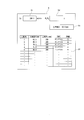
上記のように回転数決定部4により駆動モータの回転数が決定されれば、工具径決定部5は、当該回転数と第1設定部2aにより設定された切削速度とから、設定された切削速度の下、工作機械において用いるべき切削工具の工具径を算出する。この場合、工具径決定部5は、Vc=π×D×n(但し、Vcは切削速度、Dは工具径、nは駆動モータの回転数)で表される式から工具径を算出する。算出された工具径は、図3に示すように、表示部8に設けられた表示領域8aに表示される。このように、ユーザーは、所望する切削速度を入力設定すれば、工作機械において用いるべき最適な工具径、すなわち工具寿命を短くすることなく切削効率を向上し得る工具径を認識することができる。
次に、ユーザーは、所定の加工条件を設定することにより、駆動モータの出力値と記憶部3に記憶される最大出力値の定常値との比率である負荷比率(%)を認識することができる。以下、詳しく説明する。なお、上記負荷比率は、主軸ロードとも呼ばれることがある。
図3に示すように、ユーザーは、設定部2の制御により表示部8に表示された入力部8eに対し、切削工具による切込深さap、切削工具による切込幅ae、切削工具の刃先形状に基づいて決まる1刃あたり送り量の最大値fz、駆動モータの回転数n、切削工具の刃数z、予め取得される比切削抵抗kc、及び予め取得される機械効率ηの各初期値をそれぞれ入力する。設定された各初期値は第2設定部2bにより記憶部3に記憶される。なお、上記入力部8eにおける駆動モータの回転数については、回転数決定部4により決定された回転数が入力部8eの所定箇所に自動入力されるように構成されている。
ユーザーにより上記各初期値が設定されると、モータ出力値算出部6(図1参照)は、下式により駆動モータの出力値Pcを算出する。算出された出力値は記憶部3に記憶されると共に表示部8の表示領域8a(図3参照)に表示される。これにより、ユーザーは駆動モータの出力値を視認することができる。
Pc=ap×ae×fz×n×z×kc/(60×106×η)
但し、上記機械効率は実切削により予め取得される。また、上記比切削抵抗は下式により予め取得される。
kc=kc1×hm -mc×(1-γ0/100)
但し、kc1は切屑厚さが1mmのときの比切削抵抗であり、mcは比切削抵抗が切屑厚さによって変動する際の係数であり、γ0は工具のすくい角であり、hmは平均切屑厚さであって下式により取得されるものである。
hm=360×sinκr×ae×fz/(π×D×acos(1-2×ae/D))
なお、κrは切刃角である。
Pc=ap×ae×fz×n×z×kc/(60×106×η)
但し、上記機械効率は実切削により予め取得される。また、上記比切削抵抗は下式により予め取得される。
kc=kc1×hm -mc×(1-γ0/100)
但し、kc1は切屑厚さが1mmのときの比切削抵抗であり、mcは比切削抵抗が切屑厚さによって変動する際の係数であり、γ0は工具のすくい角であり、hmは平均切屑厚さであって下式により取得されるものである。
hm=360×sinκr×ae×fz/(π×D×acos(1-2×ae/D))
なお、κrは切刃角である。
上記のようにモータ出力値算出部6により駆動モータの出力値が算出されると、負荷比率算出部7(図1参照)は、上記駆動モータの出力値と記憶部3に記憶される駆動モータの最大出力値の定常値との比率である負荷比率を算出する。算出された負荷比率は表示部8の表示領域8a(図3参照)に表示される。これにより、ユーザーは負荷比率を視認することができる。
このように負荷比率算出部7により負荷比率が算出された後、切削能率算出部9(図1参照)は、上述のように求めた駆動モータの出力値と、比切削抵抗と、機械効率とから、下式により切削能率を算出する。算出された切削能率は表示部8の表示領域8a(図3参照)に表示される。これにより、ユーザーは切削能率を視認することができる。
Ce=ap×ae×fz×n×z
Ce=ap×ae×fz×n×z
ここで、ユーザーは、設定部2の制御により表示部8に表示された入力部8d(図3参照)に対し所望する負荷比率を入力することができる。この場合、例えば、ユーザーは、負荷比率算出部7により算出され表示された負荷比率を視認した後、当該負荷比率よりも高い所望の負荷比率を設定することができ、また、当該負荷比率よりも低い所望の負荷比率を設定することもできる。変更設定された負荷比率は第3設定部2cにより記憶部3に記憶される。
ユーザーにより負荷比率が変更設定されると、モータ出力値算出部6(図1参照)は、変更設定された負荷比率を基に、駆動モータの出力値を再算出する。再算出された駆動モータの出力値は記憶部3に記憶されると共に表示部8の表示領域8aに表示される。これにより、ユーザーは、再算出された駆動モータの出力値を視認することができる。
モータ出力値算出部6により駆動モータの出力値が変更されると、上述のPc=ap×ae×fz×n×z×kc/(60×106×η)の式から分かるように、切込深さ、切込幅、及び1刃あたり送り量からなる主要加工条件のうち少なくとも一つを変更する必要性が生じる。そこで、条件変更部10(図1参照)により、上記主要加工条件のうち少なくとも一つが自動で変更されるように構成されている。条件変更部10により変更された上記主要加工条件及び変更されなかった上記主要加工条件は、表示部8の表示領域8b(図3参照)に表示される。これにより、ユーザーは、上記主要加工条件のうち変更されたものと変更されなかったものとの双方を認識することができる。
再算出された駆動モータの出力値及び条件変更部10により変更された値を基に、切削能率算出部9(図1参照)により切削能率が再算出される。再算出された切削能率は表示部8の表示領域8aに表示される。これにより、ユーザーは、再算出された切削能率を視認することができる。
そして、ユーザーは、再算出された切削能率を視認した後、上記入力部8eに対し上記主要加工条件(すなわち、切込深さ、切込幅、及び1刃あたり送り量)のうち少なくとも一つの所望値を入力することができる。例えば、ユーザーは、再算出された切削能率よりも高い切削能率を所望する場合には、上記主要加工条件のうち少なくとも一つを高い値(つまり現在値よりも高い値)に変更設定することができる。この場合、ユーザーは、表示部8の表示領域8bに表示された主要加工条件の値を基準として、当該主要加工条件の値を高い値に設定することができる。ユーザーにより変更された主要加工条件の値は第4設定部2dにより記憶部3に記憶される。
次に、切削能率算出部9(図1参照)は、ユーザーにより変更された主要加工条件及び変更されなかった主要加工条件の各値を基に、切削能率を再算出する。また、負荷比率算出部7(図1参照)は、再算出された切削能率を基に負荷比率を再算出する。再算出された切削能率及び負荷比率は表示部8の表示領域8a(図3参照)に表示される。これにより、ユーザーは、自身が変更した主要加工条件を基に再算出された切削能率及び負荷比率を視認することができる。このように、上記主要加工条件を種々変更することにより複数の切削能率を取得することができ、ユーザーはそのうちから適切な一つの切削能率を決定することができる。
ここで、上記の通り、負荷比率を変更した場合の切削能率を探ることが可能であるが、以下に説明するように、負荷比率を維持した状態で上記主要加工条件を変更することにより、切削能率を探ることも可能である。
図3に示すように、ユーザーは、表示部8の表示領域8aにおける「負荷比率」の左方に表示された維持ボタン11を押下することにより、表示部8の表示領域8aに表示されている負荷比率を維持する(つまり固定する)ことができる。この場合、維持する負荷比率は、ユーザーによる入力部8eに対する入力後に算出された負荷比率であってもよいし、ユーザーによる入力部8dに対する入力により所望値に変更設定された負荷比率であってもよい。
次いで、ユーザーは、上記入力部8eに対し上記主要加工条件(すなわち、切込深さ、切込幅、及び1刃あたり送り量)のうち少なくとも一つの所望値を入力することができる。ユーザーにより変更された主要加工条件の値は第5設定部2eにより記憶部3に記憶される。ユーザーにより主要加工条件が変更されると、切削能率算出部9は、上記負荷比率を維持した状態で、上記変更設定された値を基に切削能率を再算出する。再算出された切削能率は表示部8の表示領域8aに表示される。これにより、ユーザーは、負荷比率を維持した状態で、自身が変更した主要加工条件を基に再算出された切削能率を視認することができる。このように、上記主要加工条件を種々変更することにより、負荷比率を維持した状態で複数の切削能率を得ることができ、ユーザーはそのうちから適切な一つの切削能率を決定することができる。
以上のように、本実施形態に係る加工条件決定装置1によれば、ユーザーにより設定された切削速度を維持した状態(つまり、切削速度を増加させない状態)で、工具径決定部5により、駆動モータの回転数に応じた工具径、すなわち、切削効率を向上し得る加工条件としての工具径を算出することができる。したがって、工作機械において上記工具径の切削工具を用いて加工を行えば、当該切削工具の工具寿命を短くすることなく、切削効率を向上することが可能となる。
また、本実施形態によれば、第2設定部2bにより設定された上記各初期値を基にモータ出力値算出部6により駆動モータの出力値が算出される。そして、負荷比率算出部7により負荷比率が算出される。これにより、ユーザーは、上記各初期値の下、工具径決定部5により算出された工具径の切削工具を採用する場合における負荷比率を容易に認識することができる。
また、本実施形態によれば、切削能率算出部9により切削能率が算出される。これにより、ユーザーは、上記各初期値の下における切削能率を容易に認識することができる。
また、本実施形態によれば、ユーザーは、表示部8の表示領域8aに表示された負荷比率を認識した後、当該負荷比率を所望値に変更設定することができる。このように負荷比率を変更した場合に、これに伴って条件変更部10により主要加工条件が自動で変更されるように構成されており、当該主要加工条件の変更後における切削能率が切削能率算出部9により再算出される。このような構成において、ユーザーは、負荷比率を所望値に変更した場合における切削能率や主要加工条件を認識することができる。
また、本実施形態によれば、ユーザーは、表示された切削能率を認識した後、上記主要加工条件のうち少なくとも一つを変更設定することができる。そして、変更された主要加工条件を基に、切削能率算出部9により切削能率が再算出される。再算出された切削能率を基に、負荷比率算出部7により負荷比率が再算出される。このような構成により、ユーザーは、上記主要加工条件を種々変更することによって、得られる複数の切削能率及び負荷比率から何れかを見極めることができる。
さらに、本実施形態によれば、上記負荷比率を維持した状態で(すなわち負荷比率を変えない状態で)、上記主要加工条件のうち少なくとも一つを変更設定することができる。変更された主要加工条件を基に、切削能率算出部9により切削能率が再算出される。このような構成により、ユーザーは、上記主要加工条件を種々変更することによって、負荷比率を変えない状態で得られる複数の切削能率から何れかを見極めることができる。
続いて、本発明の一実施形態に係る切削工具選択装置について図面を参照しつつ説明する。本実施形態の切削工具選択装置は、複数の切削工具を用いて加工を行う工作機械において使用すべき適切な切削工具を選択するものである。
図4に示すように、本実施形態の切削工具選択装置50は、回転数決定部4、工具径決定部5、表示部8、設定部51、第1記憶部52、第2記憶部53、及び工具選択部54を備える。本実施形態では、上記の回転数決定部4、工具径決定部5、設定部51、第1記憶部52、第2記憶部53、及び工具選択部54により構成される演算装置50aをNC装置に組み込んでもよく、或いは、上記演算装置50aをNC装置との間で通信を行う外部装置として適用してもよい。なお、回転数決定部4、工具径決定部5及び表示部8については、図1の加工条件決定装置1のものと同様であるため説明を省略する。設定部51及び工具選択部54は、切削工具選択装置50に設けられたCPUがメモリに記憶された所定のプログラムを実行することで機能的に実現されるものである。
本実施形態の切削工具選択装置50によれば、ユーザーが所望する切削速度を設定すれば、工作機械において前記設定された切削速度で切削工具による加工を行う場合に、当該切削工具の工具寿命を短くすることなく、切削効率を向上し得る工具径を有する切削工具を選択することができる。以下、詳しく説明する。
上記の第2記憶部53は、複数の切削工具の各々の工具径を予め記憶する。この複数の切削工具は、工作機械に設けられる工具マガジンに収納された複数の切削工具であってもよいし、工作機械の外部(例えば倉庫等)に保管される複数の切削工具であってもよい。本実施形態では、図5に示すように、第2記憶部53に記憶される各工具の工具ナンバー、工具径、工具長、工具型(工具タイプ)、及び後記の評価が表示部8の表示領域8cに表示される。
図5に示すように、まず、ユーザーは、設定部51の制御により表示部8に表示された入力部8cに対し所望の切削速度を入力する。この切削速度の設定情報は設定部51により第1記憶部52に記憶される。その後、回転数決定部4が駆動モータの回転数を決定し、工具径決定部5が上記設定された切削速度の下、工作機械において用いるべき切削工具の工具径を算出する点については上記加工条件決定装置1と同様である。図5に示すように、工具径決定部5により算出された工具径は表示部8の表示領域8aに表示される。これにより、ユーザーは算出された工具径を視認することができる。
次に、上記の工具選択部54は、工具径決定部5により算出された工具径と第2記憶部53に記憶される工具径とを比較する。例えば、工具径決定部5により算出された工具径が63.0mmであるとする。この場合、第2記憶部53に記憶される工具径のうち上記算出された工具径と一致するものがあるので、工具選択部54により、上記一致した工具径が選択される。これによって、図5に示すように、工具選択部54により選択された工具径の評価が「〇」として表示部8の表示領域8fに表示される。
ここで、工具径決定部5により算出された工具径(例えば63.0mm)と同じ工具径のデータが第2記憶部53に無い場合には、工具選択部54により、上記算出された工具径に最も近い工具径が選択される。この場合、図6に示すように、上記算出された63.0mmの工具径に最も近い64.0mmの工具径の評価が「〇」として表示される。なお、図5に示すように、工具径決定部5により算出された工具径を基準に差が例えば±3mm以下の工具径については、その評価を「△」として表示してもよい。また、工具径決定部5により算出された工具径を基準に差が例えば±3mmを超える工具径については、その評価を「×」として表示してもよい。以上のように、ユーザーは、所望する切削速度を設定すれば、工作機械において用いるべき最適な工具径、すなわち工具寿命を短くすることなく切削効率を向上し得る工具径を認識できるようになっている。
このように、本実施形態に係る切削工具選択装置50によれば、ユーザーにより設定された切削速度を維持した状態(つまり、切削速度を増加させない状態)で、工具径決定部5により、駆動モータの回転数に応じた工具径、すなわち、切削効率を向上し得る工具径を算出することができる。そして、算出された工具径を基に、工具選択部54により、工具径が一致する切削工具又は当該工具径に最も近い工具径を有する切削工具が選択される。したがって、工具選択部54により選択された切削工具を工作機械において用いて加工を行えば、当該切削工具の工具寿命を短くすることなく、切削効率を向上することが可能となる。
以上、本発明の一実施形態について説明したが、本発明は上記内容に限定されるものではなく、次のような変形例を適用することができる。
上記実施形態では、回転数決定部4は、工具径を極力大きくし、より少ないパスで加工することにより切削効率を向上するという観点で、駆動モータの最大出力値の定常値に対応する回転数のうち最小値を駆動モータの回転数として決定するようにしたが、これに限定されるものではない。回転数決定部4は、上記定常値に対応する最大値を駆動モータの回転数として決定してもよいし、また、上記定常値に対応する、最小値と最大値との間における回転数を駆動モータの回転数として決定してもよい。
また、上記実施形態では、駆動モータの最大出力値の定常値に対応する回転数のうち最小値を駆動モータの回転数として決定し、より大きな工具径を算出するようにしたが、これに限定されるものではなく、加工経路を予め認識した上で、大きい工具径にすべきか又は小さい工具径にすべきかについて、切削効率の側面から判別し、その判別結果をユーザーに通知するように構成してもよい。
また、上記実施形態は、工作機械において、ある工具型(例えばエンドミル)が初期に採用されていた場合に、同種の工具型であって、工具寿命を短くすることなく切削効率を向上することが可能な工具径を有する切削工具を提案することを想定するものであるが、これに限定されるものではない。上記工具径を有する異種の工具型(例えばフライス)の切削工具を提案するようにしてもよい。
さらに、切削能率と、切込深さ及び切込幅を除く上記各初期値とを維持した状態で、切込幅を変更設定したときの切込深さをアウトプットとして算出し表示(図3参照)するように構成してもよい。逆に、切削能率と、切込深さ及び切込幅を除く上記各初期値とを維持した状態で、切込深さを変更設定したときの切込幅をアウトプットとして算出し表示(同図参照)するように構成してもよい。つまり、切込幅の変更時における切込深さの変化や切込深さの変更時における切込幅の変化を確認できるように構成してもよい。
1 加工条件決定装置
2 設定部
2a 第1設定部
2b 第2設定部
2c 第3設定部
2d 第4設定部
2e 第5設定部
3 記憶部
4 回転数決定部
5 工具径決定部
6 モータ出力値算出部
7 負荷比率算出部
8 表示部
9 切削能率算出部
10 条件変更部
50 切削工具選択装置
51 設定部
52 第1記憶部
53 第2記憶部
54 工具選択部
2 設定部
2a 第1設定部
2b 第2設定部
2c 第3設定部
2d 第4設定部
2e 第5設定部
3 記憶部
4 回転数決定部
5 工具径決定部
6 モータ出力値算出部
7 負荷比率算出部
8 表示部
9 切削能率算出部
10 条件変更部
50 切削工具選択装置
51 設定部
52 第1記憶部
53 第2記憶部
54 工具選択部
Claims (7)
- 工作機械に用いられる切削工具の加工条件を決定する加工条件決定装置であって、
前記切削工具の切削速度を設定する第1設定部と、
前記切削工具を保持する軸を回転させる駆動モータの最大出力値と、当該最大出力値に対応する当該駆動モータの回転数とを記憶する記憶部と、
前記記憶部に記憶される前記駆動モータの最大出力値の定常値を取得し、取得された前記最大出力値の定常値に対応する前記駆動モータの回転数を決定する回転数決定部と、
前記第1設定部により設定された前記切削速度及び前記回転数決定部により決定された前記駆動モータの回転数から、前記切削工具の工具径を算出する工具径決定部と、を備えることを特徴とする加工条件決定装置。 - 前記切削工具による切込深さap、切込幅ae、前記切削工具の刃先形状に基づいて決まる1刃あたり送り量の最大値fz、前記回転数決定部により決定される前記駆動モータの回転数n、前記切削工具の刃数z、前記工具径を基に予め取得される比切削抵抗kc、及び予め取得される機械効率ηをそれぞれ初期値として設定する第2設定部と、
下式により前記駆動モータの出力値Pcを算出するモータ出力値算出部と、
前記出力値と前記記憶部に記憶される前記最大出力値の定常値との比率である負荷比率を算出する負荷比率算出部と、
前記負荷比率を表示する表示部と、を備えることを特徴とする請求項1に記載の加工条件決定装置。
Pc=ap×ae×fz×n×z×kc/(60×106×η) - 前記出力値と、前記比切削抵抗と、前記機械効率とから、下式で表される切削能率Ceを算出する切削能率算出部をさらに備え、
前記表示部は、前記切削能率を表示するように構成されていることを特徴とする請求項2に記載の加工条件決定装置。
Ce=ap×ae×fz×n×z - 前記負荷比率を所望値に変更設定する第3設定部を備え、
前記モータ出力値算出部は、前記変更設定された負荷比率を基に、前記出力値を再算出するように構成され、
前記再算出された出力値を基に、前記切込深さ、前記切込幅、及び前記1刃あたり送り量からなる主要加工条件のうち少なくとも一つを変更する条件変更部をさらに備え、
前記切削能率算出部は、前記再算出された出力値及び前記条件変更部により変更された値を基に、前記切削能率を再算出するように構成され、
前記表示部は、前記再算出された切削能率からなる第1情報と、前記条件変更部により変更された前記主要加工条件及び変更されなかった前記主要加工条件からなる第2情報とのうち、少なくとも一方の情報を表示するように構成されていることを特徴とする請求項3に記載の加工条件決定装置。 - 前記切込深さ、前記切込幅、及び前記1刃あたり送り量からなる主要加工条件のうち少なくとも一つを変更設定する第4設定部をさらに備え、
前記切削能率算出部は、前記第4設定部により変更設定された値に基づいて前記切削能率を再算出するように構成され、
前記負荷比率算出部は、前記再算出された切削能率に基づいて前記負荷比率を再算出するように構成され、
前記表示部は、前記再算出された切削能率及び前記再算出された負荷比率のうち少なくとも一方を表示するように構成されていることを特徴とする請求項3に記載の加工条件決定装置。 - 前記負荷比率を維持した状態で、前記切込深さ、前記切込幅、及び前記1刃あたり送り量のうち少なくとも一つを変更設定する第5設定部をさらに備え、
前記切削能率算出部は、前記第5設定部により変更設定された値に基づいて前記切削能率を再算出するように構成され、
前記表示部は、前記再算出された切削能率を表示するように構成されていることを特徴とする請求項2乃至4の何れか1項に記載の加工条件決定装置。 - 複数の切削工具を用いて加工を行う工作機械において、使用すべき前記切削工具を選択する切削工具選択装置であって、
前記切削工具の切削速度を設定する設定部と、
前記切削工具を保持する軸を回転させる駆動モータの最大出力値と、当該最大出力値に対応する当該駆動モータの回転数とを記憶する第1記憶部と、
前記第1記憶部に記憶される前記駆動モータの最大出力値の定常値を取得し、取得された前記最大出力値の定常値に対応する前記駆動モータの回転数を決定する回転数決定部と、
前記設定部により設定された前記切削速度及び前記回転数決定部により決定された前記駆動モータの回転数から、前記切削工具の工具径を算出する工具径決定部と、
前記複数の切削工具の各々の工具径を予め記憶する第2記憶部と、
前記工具径決定部により算出された前記工具径と前記第2記憶部に記憶される前記工具径とを比較し、前記工具径が一致する場合には、当該工具径を有する前記切削工具を選択し、前記工具径が一致しない場合には、前記工具径決定部により算出された前記工具径に最も近い工具径を有する前記切削工具を選択する工具選択部と、を備えることを特徴とする切削工具選択装置。
Priority Applications (3)
| Application Number | Priority Date | Filing Date | Title |
|---|---|---|---|
| CN201780061061.0A CN109789525A (zh) | 2016-10-04 | 2017-05-24 | 加工条件决定装置及切削工具选择装置 |
| DE112017005035.9T DE112017005035T5 (de) | 2016-10-04 | 2017-05-24 | Vorrichtung zur Bestimmung von Bearbeitungsbedingungen und Auswahlvorrichtung für Zerspanungswerkzeuge |
| US16/335,087 US11396074B2 (en) | 2016-10-04 | 2017-05-24 | Machining condition-determining device and cutting tool selection apparatus |
Applications Claiming Priority (2)
| Application Number | Priority Date | Filing Date | Title |
|---|---|---|---|
| JP2016196537A JP6353884B2 (ja) | 2016-10-04 | 2016-10-04 | 加工条件決定装置及び切削工具選択装置 |
| JP2016-196537 | 2016-10-04 |
Publications (1)
| Publication Number | Publication Date |
|---|---|
| WO2018066166A1 true WO2018066166A1 (ja) | 2018-04-12 |
Family
ID=61832105
Family Applications (1)
| Application Number | Title | Priority Date | Filing Date |
|---|---|---|---|
| PCT/JP2017/019321 Ceased WO2018066166A1 (ja) | 2016-10-04 | 2017-05-24 | 加工条件決定装置及び切削工具選択装置 |
Country Status (5)
| Country | Link |
|---|---|
| US (1) | US11396074B2 (ja) |
| JP (1) | JP6353884B2 (ja) |
| CN (1) | CN109789525A (ja) |
| DE (1) | DE112017005035T5 (ja) |
| WO (1) | WO2018066166A1 (ja) |
Families Citing this family (3)
| Publication number | Priority date | Publication date | Assignee | Title |
|---|---|---|---|---|
| EP3875194A1 (de) * | 2020-03-05 | 2021-09-08 | Hilti Aktiengesellschaft | Verfahren zur ermittlung einer empfehlung eines einzulegenden ganges für ein kernbohrgerät, sowie kernbohrgerät |
| EP4364888A4 (en) * | 2021-07-13 | 2025-05-07 | DMG Mori Co., Ltd. | MACHINING TIME ESTIMATING METHOD, MACHINING TIME ESTIMATING DEVICE, COMPUTER PROGRAM, AND RECORDING MEDIUM |
| JP7797243B2 (ja) * | 2022-02-25 | 2026-01-13 | 本田技研工業株式会社 | 加工装置、評価装置及び評価方法 |
Citations (4)
| Publication number | Priority date | Publication date | Assignee | Title |
|---|---|---|---|---|
| JPH05237740A (ja) * | 1992-02-26 | 1993-09-17 | Nec Software Ltd | Camシステムにおける平面加工条件決定方式 |
| JPH11129141A (ja) * | 1997-10-31 | 1999-05-18 | Toyota Motor Corp | 加工情報自動作成評価装置 |
| JPH11277371A (ja) * | 1998-03-24 | 1999-10-12 | Yamazaki Mazak Corp | 加工プログラム作成支援装置 |
| JP2012155473A (ja) * | 2011-01-25 | 2012-08-16 | Okuma Corp | 数値制御情報作成装置 |
Family Cites Families (14)
| Publication number | Priority date | Publication date | Assignee | Title |
|---|---|---|---|---|
| JPS5258178A (en) * | 1975-11-10 | 1977-05-13 | Ikegai Corp | Apparatus for ordering change in speed of spindle |
| JP3702496B2 (ja) | 1995-07-10 | 2005-10-05 | 三菱電機株式会社 | 数値制御装置を用いた加工方法 |
| JP4738585B2 (ja) * | 2000-10-26 | 2011-08-03 | シチズンホールディングス株式会社 | 加工プログラムのグラフ表示方法及びそのための装置 |
| JP4112436B2 (ja) * | 2003-06-03 | 2008-07-02 | スター精密株式会社 | 工作機械の数値制御装置と工作機械の数値制御方法 |
| CN102022116B (zh) * | 2009-09-23 | 2013-04-10 | 中国神华能源股份有限公司 | 用于连采设备的配套方法和系统 |
| CN102331749B (zh) * | 2010-07-15 | 2013-06-05 | 沈阳黎明航空发动机(集团)有限责任公司 | 一种数控加工工艺参数优化方法 |
| CN102049559B (zh) * | 2010-11-09 | 2012-03-14 | 中国电子科技集团公司第十四研究所 | 一种数控铣削刀具的快速优选方法 |
| JP5689396B2 (ja) * | 2011-10-06 | 2015-03-25 | 株式会社日立製作所 | 生産計画装置および生産計画方法 |
| JP5670501B2 (ja) * | 2013-03-21 | 2015-02-18 | ファナック株式会社 | 切削条件表示装置 |
| KR102092968B1 (ko) * | 2013-06-10 | 2020-03-24 | 두산공작기계 주식회사 | 회전 절삭공구의 초기 축방향 절삭 깊이 설정방법 및 제어장치 |
| JP5960189B2 (ja) * | 2014-04-18 | 2016-08-02 | ファナック株式会社 | 加工サイクル生成機能を有する数値制御装置およびプログラム編集方法 |
| US10671046B2 (en) * | 2014-11-26 | 2020-06-02 | Mitsubishi Electric Corporation | Method and apparatus for applying vibration and machining an object |
| JP5956619B2 (ja) * | 2015-01-13 | 2016-07-27 | ファナック株式会社 | 加工条件に応じてパラメータを調整するパラメータ自動調整装置 |
| JP2016150428A (ja) * | 2015-02-19 | 2016-08-22 | ファナック株式会社 | 工作機械 |
-
2016
- 2016-10-04 JP JP2016196537A patent/JP6353884B2/ja active Active
-
2017
- 2017-05-24 US US16/335,087 patent/US11396074B2/en active Active
- 2017-05-24 DE DE112017005035.9T patent/DE112017005035T5/de not_active Withdrawn
- 2017-05-24 WO PCT/JP2017/019321 patent/WO2018066166A1/ja not_active Ceased
- 2017-05-24 CN CN201780061061.0A patent/CN109789525A/zh active Pending
Patent Citations (4)
| Publication number | Priority date | Publication date | Assignee | Title |
|---|---|---|---|---|
| JPH05237740A (ja) * | 1992-02-26 | 1993-09-17 | Nec Software Ltd | Camシステムにおける平面加工条件決定方式 |
| JPH11129141A (ja) * | 1997-10-31 | 1999-05-18 | Toyota Motor Corp | 加工情報自動作成評価装置 |
| JPH11277371A (ja) * | 1998-03-24 | 1999-10-12 | Yamazaki Mazak Corp | 加工プログラム作成支援装置 |
| JP2012155473A (ja) * | 2011-01-25 | 2012-08-16 | Okuma Corp | 数値制御情報作成装置 |
Also Published As
| Publication number | Publication date |
|---|---|
| US11396074B2 (en) | 2022-07-26 |
| CN109789525A (zh) | 2019-05-21 |
| JP2018058144A (ja) | 2018-04-12 |
| DE112017005035T5 (de) | 2019-06-19 |
| JP6353884B2 (ja) | 2018-07-04 |
| US20210276136A1 (en) | 2021-09-09 |
Similar Documents
| Publication | Publication Date | Title |
|---|---|---|
| JP6381665B2 (ja) | 工作機械の制御方法および工作機械の制御装置 | |
| JP6546707B2 (ja) | 工作機械およびその制御装置 | |
| JP5778801B2 (ja) | 工作機械の数値制御装置 | |
| JP6353884B2 (ja) | 加工条件決定装置及び切削工具選択装置 | |
| CN105629887A (zh) | 控制具有切削条件变更功能的机床的控制装置 | |
| WO2015037143A1 (ja) | 工具経路評価方法、工具経路生成方法、及び工具経路生成装置 | |
| JP5683234B2 (ja) | 工作機械の振動抑制装置及び方法 | |
| CN117440869A (zh) | 用于工具机的振动切削条件设定装置 | |
| US10274938B2 (en) | Numerical control unit and NC program creating unit | |
| CN108693831B (zh) | 模拟装置、程序生成装置、控制装置及计算机的显示方法 | |
| CN112743392A (zh) | 机床中的主轴转速的监视装置及监视方法、机床 | |
| CN110536773B (zh) | 加工控制装置、工作机械及加工控制方法 | |
| JP5726041B2 (ja) | 工具経路生成装置及び方法 | |
| JP5647529B2 (ja) | 数値制御情報作成装置 | |
| JP3696805B2 (ja) | 工作機械の移動位置設定方法 | |
| CN114981738A (zh) | 机床的控制装置 | |
| JP2001228909A (ja) | 工作機械及びその制御方法 | |
| JP2000105606A (ja) | 数値制御装置 | |
| JP3152053B2 (ja) | 切削条件設定方法および装置 | |
| JP4063180B2 (ja) | 金型加工工程決定装置、金型加工工程決定方法、金型加工工程決定プログラム、そのプログラムを記録したコンピュータ読取り可能な記録媒体、ncデータ作成装置、及び工作機械制御装置 | |
| WO2024189907A1 (ja) | 加工経路表示装置およびコンピュータ読み取り可能な記憶媒体 | |
| JP7695523B2 (ja) | 工作機械 | |
| JP2002297218A (ja) | 工作機械の生産管理方法 | |
| TW202544579A (zh) | 控制裝置及程式 | |
| CN116324643A (zh) | 数值控制装置、制造机械以及制造机械的控制方法 |
Legal Events
| Date | Code | Title | Description |
|---|---|---|---|
| 121 | Ep: the epo has been informed by wipo that ep was designated in this application |
Ref document number: 17858006 Country of ref document: EP Kind code of ref document: A1 |
|
| 122 | Ep: pct application non-entry in european phase |
Ref document number: 17858006 Country of ref document: EP Kind code of ref document: A1 |