WO2015037143A1 - 工具経路評価方法、工具経路生成方法、及び工具経路生成装置 - Google Patents
工具経路評価方法、工具経路生成方法、及び工具経路生成装置 Download PDFInfo
- Publication number
- WO2015037143A1 WO2015037143A1 PCT/JP2013/074909 JP2013074909W WO2015037143A1 WO 2015037143 A1 WO2015037143 A1 WO 2015037143A1 JP 2013074909 W JP2013074909 W JP 2013074909W WO 2015037143 A1 WO2015037143 A1 WO 2015037143A1
- Authority
- WO
- WIPO (PCT)
- Prior art keywords
- tool path
- tool
- workpiece
- path
- contact area
- Prior art date
Links
Images


Classifications
-
- G—PHYSICS
- G05—CONTROLLING; REGULATING
- G05B—CONTROL OR REGULATING SYSTEMS IN GENERAL; FUNCTIONAL ELEMENTS OF SUCH SYSTEMS; MONITORING OR TESTING ARRANGEMENTS FOR SUCH SYSTEMS OR ELEMENTS
- G05B19/00—Programme-control systems
- G05B19/02—Programme-control systems electric
- G05B19/18—Numerical control [NC], i.e. automatically operating machines, in particular machine tools, e.g. in a manufacturing environment, so as to execute positioning, movement or co-ordinated operations by means of programme data in numerical form
- G05B19/19—Numerical control [NC], i.e. automatically operating machines, in particular machine tools, e.g. in a manufacturing environment, so as to execute positioning, movement or co-ordinated operations by means of programme data in numerical form characterised by positioning or contouring control systems, e.g. to control position from one programmed point to another or to control movement along a programmed continuous path
- G05B19/27—Numerical control [NC], i.e. automatically operating machines, in particular machine tools, e.g. in a manufacturing environment, so as to execute positioning, movement or co-ordinated operations by means of programme data in numerical form characterised by positioning or contouring control systems, e.g. to control position from one programmed point to another or to control movement along a programmed continuous path using an absolute digital measuring device
-
- G—PHYSICS
- G05—CONTROLLING; REGULATING
- G05B—CONTROL OR REGULATING SYSTEMS IN GENERAL; FUNCTIONAL ELEMENTS OF SUCH SYSTEMS; MONITORING OR TESTING ARRANGEMENTS FOR SUCH SYSTEMS OR ELEMENTS
- G05B19/00—Programme-control systems
- G05B19/02—Programme-control systems electric
- G05B19/18—Numerical control [NC], i.e. automatically operating machines, in particular machine tools, e.g. in a manufacturing environment, so as to execute positioning, movement or co-ordinated operations by means of programme data in numerical form
- G05B19/4093—Numerical control [NC], i.e. automatically operating machines, in particular machine tools, e.g. in a manufacturing environment, so as to execute positioning, movement or co-ordinated operations by means of programme data in numerical form characterised by part programming, e.g. entry of geometrical information as taken from a technical drawing, combining this with machining and material information to obtain control information, named part programme, for the NC machine
-
- G—PHYSICS
- G05—CONTROLLING; REGULATING
- G05B—CONTROL OR REGULATING SYSTEMS IN GENERAL; FUNCTIONAL ELEMENTS OF SUCH SYSTEMS; MONITORING OR TESTING ARRANGEMENTS FOR SUCH SYSTEMS OR ELEMENTS
- G05B19/00—Programme-control systems
- G05B19/02—Programme-control systems electric
- G05B19/18—Numerical control [NC], i.e. automatically operating machines, in particular machine tools, e.g. in a manufacturing environment, so as to execute positioning, movement or co-ordinated operations by means of programme data in numerical form
- G05B19/4097—Numerical control [NC], i.e. automatically operating machines, in particular machine tools, e.g. in a manufacturing environment, so as to execute positioning, movement or co-ordinated operations by means of programme data in numerical form characterised by using design data to control NC machines, e.g. CAD/CAM
-
- G—PHYSICS
- G05—CONTROLLING; REGULATING
- G05B—CONTROL OR REGULATING SYSTEMS IN GENERAL; FUNCTIONAL ELEMENTS OF SUCH SYSTEMS; MONITORING OR TESTING ARRANGEMENTS FOR SUCH SYSTEMS OR ELEMENTS
- G05B2219/00—Program-control systems
- G05B2219/30—Nc systems
- G05B2219/35—Nc in input of data, input till input file format
- G05B2219/35313—Display, validate tool path for boundary, surface interference
-
- G—PHYSICS
- G05—CONTROLLING; REGULATING
- G05B—CONTROL OR REGULATING SYSTEMS IN GENERAL; FUNCTIONAL ELEMENTS OF SUCH SYSTEMS; MONITORING OR TESTING ARRANGEMENTS FOR SUCH SYSTEMS OR ELEMENTS
- G05B2219/00—Program-control systems
- G05B2219/30—Nc systems
- G05B2219/39—Robotics, robotics to robotics hand
- G05B2219/39573—Tool guidance along path
-
- G—PHYSICS
- G05—CONTROLLING; REGULATING
- G05B—CONTROL OR REGULATING SYSTEMS IN GENERAL; FUNCTIONAL ELEMENTS OF SUCH SYSTEMS; MONITORING OR TESTING ARRANGEMENTS FOR SUCH SYSTEMS OR ELEMENTS
- G05B2219/00—Program-control systems
- G05B2219/30—Nc systems
- G05B2219/45—Nc applications
- G05B2219/45145—Milling
Definitions
- the present invention relates to a tool path evaluation method, a tool path generation method, and a tool path generation apparatus.
- machining using a milling tool such as an end mill has been highly automated by techniques such as numerical control and computer control.
- Such an automated machine tool is operated according to a machining program in which tool path information, workpiece machining conditions, and the like are described.
- a CAM (Computer Aided Manufacturing) device that can automatically create a machining program based on workpiece shape data created by a CAD (Computer Aided Design) device is also widespread.
- the CAM device automatically generates a machining program including a tool path by inputting various types of information related to tools, workpieces, and the like in addition to the workpiece shape data output from the CAD device.
- Japanese Patent Application Laid-Open No. 2007-257182 discloses a calculation method for calculating the amount of interference that a milling tool enters into a workpiece in virtual copying using a computer.
- the tool path included in the machining program generated by the CAM device is, for example, a path along the outer shape of the target shape of the workpiece, and is not a path considering the load applied to the tool during machining of the workpiece.
- an excessive load is applied to the tool during machining of the workpiece, the tool may be damaged, the tool may be bent and the machining accuracy may be lowered, or an excessive load may be applied to the spindle of the machine tool.
- a method for predicting a load by determining the amount of contact between a tool and a workpiece and generating a tool path has been invented.
- the cylindrical part side surface of the rotary tool can be processed even with a large amount of contact because the peripheral speed of the cutting edge is fast.
- the bottom surface of the rotary tool has a point where the peripheral speed of the cutting edge becomes zero at the center portion, and it may not be processed even with the same contact amount. Further, on the bottom surface of the rotary tool, the peripheral speed of the blade edge is slow except at the center portion, and problems such as the tool being easily damaged even with a small contact amount are likely to occur. Thus, if the load is predicted by the contact amount between the tool and the workpiece, the load cannot be appropriately evaluated.
- the tool path evaluation method of the present invention is a tool path evaluation method for evaluating a tool path when a workpiece is machined while the rotary tool moves relative to the workpiece.
- Tool path evaluation method is based on the target tool path determined in advance and the shape of the workpiece before machining by the target tool path.
- the calculation step can determine the size of the contact region as a ratio of the area of the contact region to the area of the bottom surface portion.
- the calculation step can convert the bottom surface portion of the rotary tool into a circular area on a virtual plane orthogonal to the tool rotation axis, and calculate the size of the contact area in the circular area.
- the tool path evaluation method of the present invention is a tool path evaluation method for evaluating a tool path when a workpiece is machined while the rotary tool moves relative to the workpiece.
- Tool path evaluation method is based on the target tool path determined in advance and the shape of the workpiece before machining by the target tool path.
- the tool path generation method of the present invention is a tool path generation method for generating a tool path when machining a workpiece while the rotary tool moves relative to the workpiece.
- the tool path generation method is based on a predetermined target tool path and a shape of a workpiece before machining by the target tool path, and is performing machining by the target tool path at the bottom surface portion of the rotary tool tip that intersects the tool rotation axis.
- a calculation step for calculating the size of the contact area that is predicted to actually contact the workpiece, and when the size of the contact area exceeds a predetermined threshold, the target is set until the size of the contact area is equal to or less than the threshold.
- a post-movement path generation step of generating a post-movement tool path that has moved along the tool path.
- the tool path generation method may further include an auxiliary path generation step of generating an auxiliary tool path for processing an uncut portion remaining on the workpiece after processing by the tool path after movement.
- the tool path after movement is preferably a tool path that moves the target tool path in a direction away from the workpiece along the direction of the tool rotation axis.
- the auxiliary path generation step includes an additional calculation step of calculating the size of the contact area based on the target tool path and the shape of the workpiece after machining by the moved tool path, and the additional calculation step If the size of the contact area calculated by (1) exceeds the threshold value, the additional movement that generates the moved tool path after moving the target tool path until the size of the contact area calculated by the additional calculation step is equal to or less than the threshold value.
- a post-path generation step In the auxiliary route generation step, the additional calculation step and the additional post-movement route generation step can be repeated until the size of the contact area calculated in the additional calculation step is equal to or smaller than the threshold value.
- the tool path generation method of the present invention is a tool path generation method for evaluating a tool path when machining a workpiece while the rotary tool moves relative to the workpiece.
- the tool path generation method is based on a predetermined target tool path and a shape of a workpiece before machining by the target tool path, and is performing machining by the target tool path at the bottom surface portion of the rotary tool tip that intersects the tool rotation axis.
- the tool path generation device of the present invention is a tool path generation device that generates a tool path when machining a workpiece while the rotary tool moves relative to the workpiece.
- the tool path generation device is performing machining by the target tool path at the bottom surface portion of the tip of the rotary tool that intersects the tool rotation axis based on the predetermined target tool path and the shape of the workpiece before processing by the target tool path.
- a calculation unit that calculates the size of the contact area that is predicted to actually contact the workpiece, and when the size of the contact area exceeds a predetermined threshold, the target is set until the size of the contact area is equal to or less than the threshold.
- a post-movement path generation unit that generates a post-movement tool path that has moved along the tool path, and an auxiliary path that generates an auxiliary tool path for machining an uncut portion remaining on the workpiece after machining by the post-movement tool path A generating unit.
- the calculation unit can determine the size of the contact region as a ratio of the area of the contact region to the area of the bottom surface portion.
- the calculation unit can convert the bottom surface portion of the rotary tool into a circular area on a virtual plane orthogonal to the tool rotation axis and calculate the size of the contact area in the circular area.
- the tool path after movement is preferably a tool path that moves the target tool path in a direction away from the workpiece along the direction of the tool rotation axis.
- the tool path generation device of the present invention is a tool path generation device that generates a tool path for machining a workpiece while the rotary tool moves relative to the workpiece.
- the tool path generation device is performing machining by the target tool path at the bottom surface portion of the tip of the rotary tool that intersects the tool rotation axis based on the predetermined target tool path and the shape of the workpiece before processing by the target tool path.
- a contact area calculation unit for obtaining a contact area that is expected to actually contact the workpiece, and when at least a part of the contact area overlaps a predetermined center area in the bottom surface portion, the entire contact area is detached from the center area.
- a post-movement path generator that generates a post-movement tool path that has moved the target tool path until it is completed, and generates an auxiliary tool path for machining the remaining uncut portion of the workpiece after machining using the post-movement tool path
- An auxiliary route generation unit Generates a post-movement path generator that generates a post-movement tool path that has moved the target tool path until it is completed, and generates an auxiliary tool path for machining the remaining uncut portion of the workpiece after machining using the post-movement tool path An auxiliary route generation unit.
- 1 is a block diagram of a CAM device and a machine tool according to a first embodiment.
- 1 is a schematic side view of a machine tool according to a first embodiment. It is a block diagram of the tool path change part in a 1st embodiment. It is the schematic of the 1st tool in 1st Embodiment. It is the schematic of the 2nd tool in 1st Embodiment. It is the schematic of the 3rd tool in 1st Embodiment. It is a schematic sectional drawing which shows the tool which moves along one tool path
- the tool path in the present invention means a relative path of the rotary tool with respect to the workpiece when machining the workpiece.
- FIG. 1 is a block diagram of a machining system according to the present embodiment.
- the machining system according to the present embodiment includes a CAD device 10, a CAM device 20, and a machine tool 40.
- the CAD device 10 generates target shape data D1 of a workpiece in accordance with a user operation.
- the target shape data D1 generated by the CAD device 10 is input to the CAM device 20.
- the CAM device 20 outputs a second machining program P2 for machining a workpiece into a target shape.
- the CAM device 20 includes a shape data reading unit 21 and a path setting unit 22.
- the shape data reading unit 21 reads the target shape data D1 generated by the CAD device 10.
- the path setting unit 22 generates a tool path based on the target shape data D1 and the like.
- the path setting unit 22 generates a machining program in which the tool path is set.
- the initial tool path generated by the path setting unit 22 is referred to as a target tool path R1.
- the machining program generated by the path setting unit 22 is referred to as a first machining program P1.
- the CAM device 20 includes a machining program changing unit 30.
- the machining program changing unit 30 changes the target tool path R1 and generates a post-change tool path R2. Then, the machining program change unit 30 generates a second machining program P2 in which the changed tool path is set.
- the CAM device 20 functions as a tool path generation device of the present invention.
- the second machining program P2 generated by the CAM device 20 is sent to the machine tool 40.
- the machine tool 40 includes a numerical controller 50 and servo motors S for each axis.
- the numerical controller 50 reads and interprets the second machining program P2 and performs an interpolation operation.
- the numerical controller 50 sends an operation command to each axis servo motor S based on the second machining program P2. Then, each axis servo motor S is driven according to the operation command, so that the rotary tool moves relative to the workpiece.
- FIG. 2 shows a schematic side view of the machine tool 40 in the present embodiment.
- the machine tool 40 is a table turning type machine tool that turns the workpiece W together with the rotary table 46.
- the machine tool 40 has an X axis, a Y axis, and a Z axis that are orthogonal to each other.
- the Z axis is a linear feed axis in which the main shaft 43 moves toward the workpiece W.
- the Y axis is a linear feed axis on which the carriage 47 moves.
- a linear feed axis perpendicular to the Z axis and the Y axis is set as the X axis.
- the machine tool 40 has a B axis as a rotation axis around an axis extending in parallel to the Y axis. Furthermore, it has a C axis as a rotation axis around an axis extending parallel to the Z axis.
- the machine tool 40 includes a bed 41 that is a base and a column 42 that stands on the upper surface of the bed 41.
- the machine tool 40 includes a spindle head 44 that rotatably supports the spindle 43 and a saddle 45 that supports the spindle head 44 in front of the column 42.
- the spindle head 44 supports the spindle 43 downward so that the tip of the spindle 43 faces the rotary table 46.
- a rotary tool T is attached to the tip of the main shaft 43.
- the machine tool 40 includes a rotary table 46 on which the workpiece W is disposed, and a U-shaped swing support member 48 that supports the rotary table 46.
- the machine tool 40 includes a U-shaped carriage 47 that supports a swing support member 48.
- the carriage 47 supports the swing support member 48 on a pair of support columns 47a and 47b that are separated in the Y-axis direction.
- the swing support member 48 is supported by the carriage 47 at both ends in the Y-axis direction.
- the swing support member 48 is supported so as to be swingable in the B-axis direction.
- the machine tool 40 includes a moving device that moves the rotary tool relative to the workpiece based on each moving axis.
- the moving device includes each axis servo motor S that is driven along each moving axis.
- the moving device moves the saddle 45 with respect to the column 42 in the X-axis direction.
- the moving device moves the carriage 47 with respect to the bed 41 in the Y-axis direction.
- a cavity 42c is formed so that the carriage 47 can partially enter.
- the moving device moves the spindle head 44 in the Z-axis direction with respect to the saddle 45.
- the moving device includes a rotary table 46.
- the rotary table 46 rotates in the C-axis direction with respect to the swing support member 48.
- the moving device rotates the swing support member 48 in the B-axis direction with respect to the carriage 47.
- the machine tool 40 has three linear motion axes orthogonal to each other and two rotation axes.
- the machine tool 40 of the present embodiment is a 5-axis control machine tool.
- FIG. 3 is a block diagram of the tool path changing unit 35 in the machining program changing unit 30 of the CAM device 20.
- the machining program change unit 30 includes an input unit 31, a contact area calculation unit 32a, a determination unit 33a, a display unit 34, a tool path change unit 35, and a program generation unit 39a.
- the input unit 31 receives the first machining program P1, the initial shape data D2 of the workpiece W, the tool shape data D3, and the threshold value D4.
- the first machining program P1 includes a predetermined target tool path R1.
- the target tool path R1 is, for example, a tool path along the target shape of the workpiece.
- the initial shape data D2 is, for example, shape data of a material before processing the workpiece W.
- the tool shape data D3 is data such as the type and size of the tool.
- the tool shape data D3 includes the shape and dimensions of the bottom surface portion of the rotary tool.
- the threshold value D4 is a determination value for determining the magnitude of the load applied to the bottom surface portion of the rotary tool during processing of the workpiece W.
- the load in the present embodiment means a load that acts on the rotary tool T from the workpiece W when the work W and the rotary tool T come into contact with each other.
- FIG. 4 is a side view showing one rotating tool, in which a flat end mill is shown.
- FIG. 5 is a side view showing another rotary tool, in which a radius end mill is shown.
- FIG. 6 is a side view showing still another rotary tool, in which a ball end mill is shown.
- all or a part of the tool tip that intersects the rotation axis TS of the rotary tool T is the bottom surface portion TB of the rotary tool T.
- a flat tool tip perpendicular to the rotation axis TS can be used as the bottom surface portion TB.
- intersects rotation axis TS can be made into the bottom face part TB. More specifically, the angle ⁇ 1 of the vertex of the virtual cone whose apex is the tool center point a of the ball end mill can be specified. And the part contained in the virtual cone among the curved-surface tool tips of a ball end mill can be made into bottom face part TB.
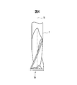
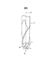
- FIG. 7 is a schematic cross-sectional view showing the rotary tool T that processes the workpiece W while moving relative to the workpiece W.
- FIG. 8 is an enlarged perspective view showing a portion of the rotary tool T in FIG.
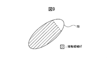
- FIG. 9 is a perspective view showing a bottom portion TB of the rotary tool T in FIG.
- An arrow A1 in FIG. 7 indicates the traveling direction of the rotary tool T that moves relative to the workpiece W along a certain tool path.
- the rotation axis TS of the rotary tool T is inclined in the direction opposite to the traveling direction with respect to the virtual plane VP1 perpendicular to the traveling direction.
- the virtual plane VP1 is a plane passing through the tool tip point b.
- a load from the workpiece W may act on the bottom surface portion TB of the rotary tool T that moves relative to the workpiece W. Therefore, in the present embodiment, it is determined whether or not the tool path is appropriate in the case described above.
- the state in which the rotation axis TS is inclined in the direction opposite to the traveling direction is a state in which the rotation axis TS of the rotary tool T is located behind the virtual plane VP1 (that is, on the side opposite to the traveling direction).
- the contact area calculation unit 32a in the present embodiment calculates the size of the contact area AT based on the target tool path R1 and the shape of the workpiece W before processing. For example, the contact area calculation unit 32a calculates the ratio of the area of the contact area AT to the area of the bottom surface portion TB. Thereby, the process of the contact area
- the contact area calculation unit 32a may calculate the dimension of the contact area AT with respect to the dimension (for example, diameter, outer periphery, etc.) of the bottom surface portion TB.
- the contact area calculation unit 32a can also calculate the ratio of the length of the outer circumference of the portion where the contact area AT exists in the outer circumference of the bottom surface portion TB.
- the calculated size of the contact area AT is transmitted to the determination unit 33a.
- the contact area calculation unit 32a converts the actual bottom surface portion TB of the rotary tool T into a circular area on a virtual plane orthogonal to the rotation axis TS, and calculates the size of the contact area AT in the circular area. be able to.
- FIG. 10 is a schematic view showing a side surface and a circular region of one rotary tool, and shows a radius end mill.
- the actual bottom surface portion TB of the rotary tool T is converted into a circular area AR whose center coincides with the rotation axis TS on the virtual plane VP2 orthogonal to the rotation axis TS.
- the determination unit 33a compares the size of the contact area AT with the threshold value D4 for each of the moving points on the target tool path R1 set at predetermined intervals.
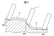
- FIG. 11 is a cross-sectional view schematically showing the rotary tool T that moves relative to the workpiece W along the target tool path R1.
- FIG. 11 shows movement points MP31, MP32, and MP33 on the target tool path R1.
- the determination unit 33a determines that the target tool path R1 is inappropriate when the size of the contact area AT exceeds the threshold D4 at the moving point on the target tool path R1.
- a moving point where the size of the contact area AT exceeds the threshold value D4 is particularly referred to as an overload moving point.
- the rotary tool T advances from the left to the right, and cutting is performed on the side surface of the rotary tool T.
- the size of the contact area AT becomes zero, and it is determined that the tool path is appropriate.
- the rotary tool T advances from the top to the bottom, and the entire bottom surface portion TB of the rotary tool T comes into contact with the cutting, and the moving point MP32 is determined to be an overload moving point.
- the determination unit 33a determines that the target tool path R1 is appropriate when the size of the contact area AT is equal to or less than the threshold value D4 at any moving point on the target tool path R1. In this case, the determination unit 33a generates the changed tool path R2 that is the same as the target tool path R1, and sends the generated tool path R2 to the program generation unit 39a.
- the program generation unit 39a generates a second machining program P2 based on the changed tool path R2.
- the tool path changing unit 35 includes a post-movement path generation unit 37a, an auxiliary path generation unit 38, and a program generation unit 39b.
- the post-movement path generation unit 37a generates a post-movement tool path R3 that moves the target tool path R1 until the size of the contact area AT is equal to or less than the threshold value D4 when the target tool path R1 is determined to be inappropriate.
- the post-movement tool path R3 is, for example, a tool path in which a part or all of the target tool path R1 is moved in a direction away from the workpiece W along the rotation axis TS.
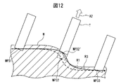
- FIG. 12 is a sectional view schematically showing the rotary tool T that moves relative to the workpiece W along the post-movement tool path R3 that avoids the overload movement point MP32 of FIG.
- the post-movement path generation unit 37a moves the overload movement point MP32 on the target tool path R1 in the direction away from the workpiece W along the rotational axis direction of the rotary tool T (that is, in the direction of arrow A2 in the drawing).
- a new movement point MP32 ′ is generated.
- the post-movement tool path R3 in this case is a tool path including movement points MP31, MP32 ', and MP33.
- the tool path changing unit 35 determines the overload movement point on the target tool path R1 as the rotation axis direction of the tool path T when it is determined that the target tool path R1 is inappropriate.
- the tool path R3 after movement is generated by moving along Thereby, it is possible to prevent the spindle 43 and the spindle head 44 from interfering with the workpiece W in the post-movement tool path R3.
- the post-movement path generation unit 37a can also move the overload movement point on the target tool path R1 in a direction different from the rotation axis direction of the tool path T.
- the post-movement path generation unit 37a can generate a new movement point MP32 'by changing the inclination angle of the rotation axis TS with respect to the machining surface of the workpiece W.
- the auxiliary path generation unit 38 of the present embodiment generates an auxiliary tool path for processing the uncut portion of the workpiece W.
- the auxiliary route generation unit 38 includes an additional contact area calculation unit 32b, an additional determination unit 33b, and an additional post-movement route generation unit 37b.
- the additional contact area calculation unit 32b has the same function as the contact area calculation unit 32a described above. More specifically, the additional contact area calculation unit 32b calculates the size of the contact area AT based on the target tool path R1 and the shape of the workpiece W after being processed by the post-movement tool path R3. That is, the additional contact area calculation unit 32b calculates the size of the contact area AT when machining the workpiece W after machining by the post-movement tool path R3 generated up to now according to the target tool path R1.
- the additional determination unit 33b has the same function as the determination unit 33a described above. That is, the additional determination unit 33b determines whether the target tool path R1 is appropriate by comparing the size of the contact area AT calculated by the additional contact area calculation unit 32b with the threshold value D4. The determination result by the additional determination unit 33 b is transmitted to the display unit 34. When the additional determination unit 33b determines that the target tool path R1 is appropriate, the post-movement tool path R3 generated up to the present and the target tool path R1 are combined to generate the post-change tool path R2. The generated post-change tool path R2 is sent to the program generation unit 39b. The program generation unit 39b generates a second machining program P2 based on the changed tool path R2.
- the additional post-movement route generation unit 37b has the same function as the post-movement route generation unit 37a described above. In other words, when the additional determination unit 33b determines that the target tool path R1 is inappropriate, the additional post-movement path generation unit 37b determines the target tool path R1 until the size of the contact area AT becomes equal to or less than the threshold value D4. The moved tool path R3 that has moved is generated.
- the additional contact area calculation unit 32b again calculates the size of the contact area AT when machining the workpiece W machined so far by the target tool path R1, similarly to the previous time.
- the additional determination unit 33b determines whether or not the target tool path R1 is appropriate for machining the workpiece W that has been machined so far, similarly to the previous time.
- the post-movement path generation unit 37b generates the post-movement tool path R3 again as in the previous time.
- the auxiliary path generation unit 38 repeatedly generates the post-movement tool path R3 until the size of the contact area AT becomes equal to or less than the threshold value D4.
- the auxiliary tool path is a tool path obtained by combining one or more generated post-movement tool paths R3 and the target tool path R1.
- the auxiliary tool path may be a tool path configured from the target tool path R1.
- the determination unit 33b generates a post-change tool path R2 by combining all the post-movement tool paths R3 generated by the post-movement path generation units 37a and 37b and the target tool path R1.
- the generated post-change tool path R2 is sent to the program generation unit 39b.
- the CAM device 20 of the present embodiment includes a display unit 34.
- the display unit 34 displays the determination results by the determination units 33a and 33b, information on the target tool path R1, information on the changed tool path R2, and the like on the screen.
- FIG. 13 is a flowchart showing a procedure of processing for generating the changed tool path R2 by the machining program changing unit 30.
- the machining program changing unit 30 first acquires machining data including target workpiece shape data D1, initial shape data D2, and tool shape data D3 (step S101). Subsequently, the machining program change unit 30 reads the target tool path R1 from the first machining program P1 (step S102).
- the machining program changing unit 30 reads the target shape of the workpiece W, the shape of the bottom surface portion TB of the rotary tool T, the initial shape of the workpiece W, and the threshold value D4 (step S103).
- the target shape of the workpiece W is included in the target shape data D1.
- the shape of the bottom surface portion TB is included in the tool shape data D3.
- the initial shape of the workpiece W is included in the initial shape data D2.
- FIG. 14 is a perspective view showing a target shape of the workpiece W
- FIG. 15 is a perspective view showing an initial shape of the workpiece W.
- the machining program changing unit 30 executes a calculation process for calculating the size of the contact area AT in the bottom surface portion TB of the rotary tool T based on the target tool path R1 and the initial shape of the workpiece W (step S104). ). More specifically, in the calculation step, the ratio of the area of the contact area AT to the area of the bottom surface portion TB is calculated as the size of the contact area AT. Further, in the calculation step, the actual bottom surface portion TB is converted into a circular area AR whose center coincides with the rotational axis TS on a virtual plane orthogonal to the rotational axis TS, and the size of the contact area AT in the circular area AR. Is calculated.
- the machining program changing unit 30 executes a determination process for determining whether or not the size of the contact area AT calculated in the calculation process (step S104) exceeds the threshold value D4 (step S105). More specifically, in the determination step, it is determined that the target tool path R1 is inappropriate when the size of the contact area AT exceeds the threshold value D4 at an arbitrary location on the target tool path R1. On the other hand, if the size of the contact area AT is equal to or smaller than the threshold value D4 at any location on the target tool path R1, it is determined that the target tool path R1 is appropriate. If the size of the contact area AT does not exceed the threshold value D4 (NO in step S105), the machining program changing unit 30 proceeds directly to step S107.
- the machining program changing unit 30 when the size of the contact area AT exceeds the threshold value D4 (YES in step S105), the machining program changing unit 30 generates a post-movement tool path R3 that has moved the target tool path R1. Is executed (step S106).
- the post-movement tool path R3 is, for example, a tool path that has moved all or part of the target tool path R1 in a direction away from the workpiece W along the rotation axis TS.
- the calculation process (step S104), determination process (step S105), and post-movement path generation process (step S106) described above are executed at once for all the movement points on the target tool path R1. However, these steps may be repeatedly executed for each movement point on the target tool path R1.
- step S ⁇ b> 107 the machining program change unit 30 determines whether there is an uncut portion for the target shape on the workpiece W. When there is no uncut residue on the workpiece W (NO in step S107), the machining program changing unit 30 outputs the target tool path R1 as the changed tool path R2 (step S108). On the other hand, if there is any uncut material on the workpiece W (YES in step S107), the machining program changing unit 30 executes an auxiliary route generating step for generating an auxiliary tool path for machining the uncut material portion remaining on the workpiece W. To do.
- FIG. 16 is a perspective view showing the shape of the workpiece W being processed.
- the shape indicated by the solid line in FIG. 16 is the shape of the workpiece that has been processed so far. Moreover, the shape shown with a broken line is a part of target shape. That is, the upper part of the area surrounded by the broken line in the workpiece W in FIG.
- the machining program change unit 30 performs an additional calculation process (step S104) based on the target tool path R1 and the shape of the workpiece W after machining by the post-movement tool path R3 generated so far. ), An additional determination step (step S105), and an additional post-movement route generation step (step S106). Thereafter, when it is determined that there is an uncut portion (YES in step S107), the machining program change unit 30 proceeds to step S104 again. As described above, the machining program changing unit 30 cuts the workpiece W after machining by the tool path generated up to now until the size of the contact area AT calculated by the additional determination process becomes equal to or less than the threshold value D4.
- step S104 The additional calculation process (step S104), the additional determination process (step S105), and the additional post-movement route generation process (step S106) are repeated until there is no remaining.
- Such a series of steps is an auxiliary route generation step.
- an additional post-movement path generation step is performed, an additional post-movement tool path R3 is generated.
- the auxiliary tool path in this case is a tool path obtained by combining one or more generated post-movement tool paths R3 and the target tool path R1.
- step S108 the machining program change unit 30 generates a post-change tool path R2 by combining the post-movement tool path R3 generated up to the present and the target tool path R1.
- the machining program changing unit 30 in the CAM device 20 of the present embodiment determines the size of the contact area AT in the bottom surface portion TB that is predicted to actually contact the workpiece W during machining by the target tool path R1. calculate. Then, the machining program changing unit 30 determines that the target tool path R1 is inappropriate when the size of the calculated contact area AT exceeds the threshold value D4. Therefore, according to the CAM device 20 of the present embodiment, it is possible to appropriately evaluate whether or not an excessive load is applied to the rotary tool during workpiece machining by the machine tool 40. Further, according to the CAM device 20 of the present embodiment, it is possible to generate the post-movement tool path R3 for avoiding an excessive load applied to the rotary tool.
- the tool path is changed according to a predetermined method.
- the post-movement tool path R3 may include an undesired path.
- the post-movement tool path R3 may include a path in which the traveling direction of the rotary tool T is reversed, or may include a path that bends.
- the post-movement tool path R3 is corrected in such a case to generate a post-correction tool path R3 '.
- FIG. 17 shows a schematic view of the post-movement tool path R3 in which the traveling direction of the rotary tool T greatly changes.
- Each tool path is described by a moving point and an arrow.
- the target tool path R1 includes movement points MP1a to MP6a.
- a post-movement tool path R3 is set with respect to the target tool path R1.
- the respective movement points MP1a to MP6a are moved to the movement points MP1b to MP6b by the movement of the rotary tool T along the rotation axis direction.
- the movement point MP3a of the target tool path R1 is moved to the movement point MP3b. Further, the moving point MP4a of the target tool path R1 has moved to the moving point MP4b.
- the inclination angle of the rotary tool T with respect to the workpiece changes greatly in the path from the movement point MP3a to the movement point MP4a.
- the advancing direction of the rotary tool T with respect to the workpiece when moving from the moving point MP3a to the moving point MP4a is indicated by an arrow 86.
- the traveling direction of the rotary tool T relative to the workpiece when moving from the moving point MP3b to the moving point MP4b is indicated by an arrow 87.
- FIG. 18 is a schematic diagram illustrating the traveling direction of the rotary tool T in the target tool path R1 and the traveling direction of the rotary tool T in the post-movement tool path R3.
- the arrows of the traveling directions relating to the moving points MP3a, MP4a, MP3b, and MP4b are extracted.
- the traveling direction of the rotary tool T in the target tool path R ⁇ b> 1 is indicated by an arrow 86.
- the traveling direction of the rotary tool T in the post-movement tool path R3 is indicated by an arrow 87.
- the traveling direction of the rotary tool T indicated by the arrow 86 and the traveling direction of the rotary tool T indicated by the arrow 87 are substantially opposite. That is, the traveling direction of the rotary tool T is reversed.
- the traveling direction of the rotary tool T with respect to the workpiece changes rapidly, there is a problem that a large acceleration is generated and an excessive force is applied to the machine tool. Or there exists a possibility that processing accuracy may fall.
- the post-movement tool path R3 is corrected when the advancing direction of the rotary tool T in the post-movement tool path R3 suddenly changes with respect to the direction of travel of the rotary tool T in the target tool path R1. .
- the determination angle is set to 90 °.
- the moving direction of the rotary tool T changes by 90 ° or more in the movement from the movement point MP3b to the movement point MP4b. For this reason, the route indicated by the arrow 87 can be determined to be a specific route.
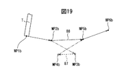
- FIG. 19 is a schematic diagram for explaining the correction of the post-movement tool path R3.
- the movement point corresponding to the specific route includes a movement point MP3b that is the start point of the arrow 87 and a movement point MP4b that is the end point of the arrow 87. For this reason, the moving point MP3b and the moving point MP4b are excluded. Then, as indicated by an arrow 88, a path that short-circuits the movement point MP2b and the movement point MP5b is generated. A path including the movement points MP1b, MP2b, MP5b, and MP6b corresponds to the corrected tool path R3 '. In this way, it is possible to exclude a path in which the traveling direction changes rapidly from the post-movement tool path R3.
- FIG. 20 shows a schematic view of the post-movement tool path R3 in which the tool path is bent.
- the post-movement tool path R3 is indicated by an arrow 91, an arrow 92, and an arrow 93.
- the post-movement tool path R3 proceeds in the direction indicated by the arrow 91 and then proceeds in the direction indicated by the arrow 92.
- the post-movement tool path R3 is bent. That is, the tool path is bent.
- the tool path is also bent when it travels in the direction shown by arrow 92 and then travels in the direction shown by arrow 93.
- the bending path is changed to a curved path.
- the bending tool path indicated by arrows 91, 92, 93 is corrected to a curved tool path indicated by arrows 99, 93.
- the path bent toward the outside of the workpiece is changed to a concave curved path.
- the path bent toward the inside of the workpiece is changed to a curved path. That is, the path is changed so that the corrected tool path is positioned outside the workpiece with respect to the post-movement tool path.
- the path indicated by the arrow 99 corresponds to the corrected tool path R3 '.
- FIG. 21 shows a graph of the amount of movement of the rotary tool T in the direction of the rotation axis with respect to the position of the moving point.
- a post-movement tool path R3 is generated by moving the target tool path R1.
- the target tool path R1 includes movement points MP10a to MP14a.
- the post-movement tool path R3 includes movement points MP10b to MP14b.
- the tool path indicated by the arrow 92 is bent with respect to the tool path indicated by the arrow 91.
- the tool path indicated by the arrow 93 is bent with respect to the tool path indicated by the arrow 92.
- the moving point MP12b and the moving point MP13b are bending points. For this purpose, the tool path from the movement point MP11b to the movement point MP13b is corrected.
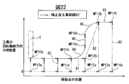
- FIG. 22 shows a graph of the corrected tool path R3 'obtained by correcting the post-movement tool path R3.
- the tool path indicated by the arrow 92 where the moving point MP13b is a bending point is corrected to a tool path of a convex arc.
- an arcuate tool path is generated so as to pass through the moving point MP13b.
- the tool path indicated by the arrow 91 whose moving point MP12b is the bending point is corrected to a concave arc tool path.
- a movement point MP15b and a movement point MP16b are newly generated.
- a tool path from the movement point MP15b to the movement point MP16b is generated.
- the diameter of the arc when generating the corrected tool path R3 ' can be set to an arbitrary value by the user.
- the arc diameter indicated by the arrow 94 and the arc diameter indicated by the arrow 95 can be set to be the same as the tool diameter.
- each movement point is moved in the rotation axis direction of rotary tool T by the stored movement amount to generate a movement point of corrected tool path R ⁇ b> 3 ′.
- the positions of the movement point MP15b and the movement point MP16b newly generated in the correction can be set by interpolating the movement point MP11b and the movement point MP13b, for example.
- the path of bending can be changed to a curved path. It is possible to avoid a sudden change in the traveling direction of the rotary tool T with respect to the workpiece W, and to suppress the burden on the machine tool. Or the fall of processing accuracy can be controlled.
- amendment is not performed.
- FIG. 23 is a flowchart showing a procedure of processing for correcting the tool path R3 after movement by the machining program changing unit 30 in the present embodiment. This process can be performed, for example, as step S106 shown in FIG. As shown in FIG. 23, the machining program change unit 30 first generates a post-movement tool path R3 that has moved in the direction of the rotation axis of the rotary tool T (step S201).
- the machining program change unit 30 determines whether there is a specific path in which the traveling direction of the rotary tool T in the post-movement tool path R3 changes by 90 ° or more with respect to the traveling direction of the rotary tool T in the target tool path R1. Is determined (step S202). If there is no specific route (NO in step S202), the machining program changing unit 30 proceeds to step S204. If there is a specific route (YES in step S202), the machining program changing unit 30 proceeds to step S203. In step S203, the machining program change unit 30 deletes the movement point corresponding to the specific route.
- the machining program change unit 30 determines whether or not there is a bent portion in the tool path R3 after movement (step S204). If there is no bent portion in the tool path R3 after movement (NO in step S204), the machining program change unit 30 ends the series of processes. If there is a bent portion in the tool path R3 after movement (YES in step S204), the machining program change unit 30 proceeds to step S205. In step S205, the machining program change unit 30 corrects the bending path into a curved path. Thereafter, the machining program change unit 30 ends the series of processes.
- FIG. 24 is a block diagram showing a basic configuration of the machining system in the present embodiment.
- the machining program changing unit 30 that functions as a tool path generation device is mounted on the numerical control device 50 of the machine tool 40 instead of the CAM device 20.
- the first machining program P1 is output from the CAM device 20, and the second machining program P2 is generated inside the machine tool 40.
- the reading interpretation unit 51 reads and interprets the second machining program P2, and sends a movement command to the interpolation calculation unit 52.
- the interpolation calculation unit 52 calculates a position command value for each interpolation cycle and sends the position command value to the servo motor control unit 53.
- the servo motor control unit 53 calculates the amount of movement of each moving axis based on the position command and drives each axis servo motor S.
- the machining program changing unit 30 in the numerical control device 50 calculates the size of the contact area AT in the bottom surface portion TB that is predicted to actually contact the workpiece W during machining by the target tool path R1. Then, the machining program changing unit 30 determines that the target tool path R1 is inappropriate when the size of the calculated contact area AT exceeds the threshold value D4. Therefore, according to the numerical control device 50 of the present embodiment, whether or not an excessive load is applied to the rotary tool during the work machining by the machine tool 40 is appropriately determined as in the CAM device 20 of the first embodiment described above. Can be evaluated. Further, according to the numerical control device 50 of the present embodiment, the post-movement tool path R3 for avoiding an excessive load applied to the rotary tool can be generated.
- the machining system of the present embodiment has the same functions and functions as those of the machining system of the first embodiment except for the contact area calculation units 32a and 32b, the determination units 33a and 33b, and the post-movement path generation units 37a and 37b. It has a configuration (see FIGS. 1 and 3).
- the center area AC in the bottom surface portion TB of the rotary tool T is determined in advance.
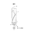
- FIG. 25 is a schematic view showing a side surface and a bottom surface of the rotary tool T in the present embodiment, and shows a ball end mill.
- a center area AC in the bottom surface portion TB of the rotary tool T is determined in advance.
- a central region AC located in the vicinity of the rotation axis TS in the bottom surface portion TB is predetermined.
- Information about the center area AC is stored in the tool shape data D3.
- the contact area calculation unit 32a executes a step of obtaining the contact area AT in the bottom surface portion TB based on the target tool path R1 and the shape of the workpiece W before processing.
- the determination unit 33a executes a step of determining that the target tool path R1 is inappropriate when at least a part of the contact area AT overlaps the center area AC in the bottom surface portion TB at an arbitrary position of the target tool path R1.
- the post-movement path generation unit 37a uses the post-movement tool path R3 that has moved along the target tool path R1 until the entire contact area AT leaves the center area AC. The process to generate is executed.
- the additional contact area calculation unit 32b executes a step of obtaining the contact area AT based on the target tool path R1 and the shape of the workpiece W after being processed by the post-movement tool path R3.
- the additional determination unit 33b executes a step of determining that the target tool path R1 is inappropriate when at least a part of the contact area AT obtained by the additional contact area calculation unit 32b overlaps the center area AC.
- the additional post-movement path generation unit 37b determines the target tool path R1 until the entire contact area AT leaves the center area AC.
- a step of generating the moved tool path R3 after the movement is executed. These additional steps are repeated until the entire contact area AT obtained by the additional contact area calculation unit 32b leaves the central area AC.
- the CAM device 20 of the present embodiment it is possible to appropriately evaluate whether or not an excessive load is applied to the rotary tool during workpiece machining by the machine tool 40, as in the first embodiment described above. Further, according to the CAM device 20 of the present embodiment, it is possible to generate the post-movement tool path R3 for avoiding an excessive load applied to the rotary tool. Furthermore, in the present embodiment, since the tool path is determined to be inappropriate when the contact area AT in the bottom surface portion TB overlaps the center region AC, in the center region AC of the bottom surface portion TB in which the peripheral speed during machining becomes particularly small. The possibility that the workpiece is cut can be reduced.
- the machining system of the present embodiment has the same functions and functions as those of the machining system of the second embodiment, except for the contact area calculation units 32a and 32b, the determination units 33a and 33b, and the post-movement path generation units 37a and 37b. It has a configuration (see FIGS. 3 and 24).
- the contact area calculation units 32a and 32b of the present embodiment have the same functions as the contact area calculation units 32a and 32b of the third embodiment.
- the determination units 33a and 33b according to the present embodiment have the same functions as the determination units 33a and 33b according to the third embodiment.
- the post-movement route generation units 37a and 37b of the present embodiment have the same functions as the post-movement route generation units 37a and 37b of the third embodiment.
- a center area AC in the bottom surface portion TB of the rotary tool T is determined in advance (see FIG. 25).
- the numerical control device 50 of the present embodiment it is possible to appropriately evaluate whether or not an excessive load is applied to the rotary tool during workpiece machining by the machine tool 40, as in the above-described embodiment. Further, according to the numerical control device 50 of the present embodiment, the post-movement tool path R3 for avoiding an excessive load applied to the rotary tool can be generated. Furthermore, in the present embodiment, since the tool path is determined to be inappropriate when the contact area AT in the bottom surface portion TB overlaps the center region AC, in the center region AC of the bottom surface portion TB in which the peripheral speed during machining becomes particularly small. The possibility that the workpiece is cut can be reduced.
- a machine tool having five moving axes is illustrated, but the present invention is not limited to this form, and any machine tool in which the tool moves relative to the workpiece can be used.
- the present invention can be applied to a three-axis machine tool having three linear motion axes.
- a rotary tool such as a flat end mill, a radius end mill, or a ball end mill is illustrated.
- any rotary tool that moves the workpiece relative to the workpiece to process the workpiece can be employed.
- the present invention can be applied to other rotary tools such as various types of milling cutters.
Landscapes
- Engineering & Computer Science (AREA)
- Physics & Mathematics (AREA)
- Human Computer Interaction (AREA)
- Manufacturing & Machinery (AREA)
- General Physics & Mathematics (AREA)
- Automation & Control Theory (AREA)
- Geometry (AREA)
- Numerical Control (AREA)
Abstract
Description
32a 接触領域算出部
32b 接触領域算出部
33a 判定部
33b 判定部
35 工具経路変更部
37a 移動後経路生成部
37b 移動後経路生成部
38 補助経路生成部
39a プログラム生成部
39b プログラム生成部
a 工具中心点
b 工具先端点
AC 中心領域
AR 円形領域
AT 接触領域
D1 目標形状データ
D2 初期形状データ
D3 工具形状データ
D4 閾値
P1 第1の加工プログラム
P2 第2の加工プログラム
R1 目標工具経路
R2 変更後工具経路
R3 移動後工具経路
R3’ 補正後工具経路
TB 底面部分
TS 回転軸線
Claims (14)
- ワークに対して回転工具が相対移動しながらワークを加工するときの工具経路を評価する工具経路評価方法であって、
予め定められた目標工具経路と、前記目標工具経路による加工前のワークの形状とに基づいて、工具回転軸線に交差する回転工具先端の底面部分における、前記目標工具経路による加工中にワークに実際に接触すると予測される接触領域の大きさを算出する算出工程と、
前記接触領域の大きさが予め定められた閾値を超える場合に、前記目標工具経路が不適切であると判定する判定工程と、を含むことを特徴とした工具経路評価方法。 - 前記算出工程は、前記接触領域の大きさを、前記底面部分の面積に対する前記接触領域の面積の割合として求める、請求項1に記載の工具経路評価方法。
- 前記算出工程は、前記回転工具が有する前記底面部分を、前記工具回転軸線に直交する仮想平面上の円形領域に変換するとともに、前記円形領域における前記接触領域の大きさを算出する、請求項1に記載の工具経路評価方法。
- ワークに対して回転工具が相対移動しながらワークを加工するときの工具経路を評価する工具経路評価方法であって、
予め定められた目標工具経路と、前記目標工具経路による加工前のワークの形状とに基づいて、工具回転軸線に交差する回転工具先端の底面部分における、前記目標工具経路による加工中にワークに実際に接触すると予想される接触領域を求める工程と、
前記接触領域の少なくとも一部が前記底面部分における予め定められた中心領域に重なる場合に、前記目標工具経路が不適切であると判定する工程と、を含むことを特徴とした工具経路評価方法。 - ワークに対して回転工具が相対移動しながらワークを加工するときの工具経路を生成する工具経路生成方法であって、
予め定められた目標工具経路と、前記目標工具経路による加工前のワークの形状とに基づいて、工具回転軸線に交差する回転工具先端の底面部分における、前記目標工具経路による加工中にワークに実際に接触すると予測される接触領域の大きさを算出する算出工程と、
前記接触領域の大きさが予め定められた閾値を超える場合に、前記接触領域の大きさが前記閾値以下になるまで前記目標工具経路を移動した移動後の工具経路を生成する移動後経路生成工程と、を含むことを特徴とした工具経路生成方法。 - 前記移動後の工具経路による加工後のワークに残存する削り残し部分を加工するための補助の工具経路を生成する補助経路生成工程をさらに含む、請求項5に記載の工具経路生成方法。
- 前記移動後の工具経路は、工具回転軸線方向に沿ってワークから離れる向きに前記目標工具経路を移動した工具経路である、請求項5に記載の工具経路生成方法。
- 前記補助経路生成工程は、
前記目標工具経路と、前記移動後の工具経路による加工後のワークの形状とに基づいて、前記接触領域の大きさを算出する追加の算出工程と、
前記追加の算出工程により算出した前記接触領域の大きさが前記閾値を超える場合に、前記追加の算出工程により算出した前記接触領域の大きさが前記閾値以下になるまで前記目標工具経路を移動した前記移動後の工具経路を生成する追加の移動後経路生成工程と、を含んでおり、
前記補助経路生成工程は、前記追加の算出工程により算出した前記接触領域の大きさが前記閾値以下になるまで、前記追加の算出工程、及び前記追加の移動後経路生成工程を繰り返す、請求項6に記載の工具経路生成方法。 - ワークに対して回転工具が相対移動しながらワークを加工するときの工具経路を評価する工具経路生成方法であって、
予め定められた目標工具経路と、前記目標工具経路による加工前のワークの形状とに基づいて、工具回転軸線に交差する回転工具先端の底面部分における、前記目標工具経路による加工中にワークに実際に接触すると予想される接触領域を求める工程と、
前記接触領域の少なくとも一部が前記底面部分における予め定められた中心領域に重なる場合に、前記接触領域の全体が前記中心領域から離脱するまで前記目標工具経路を移動した移動後の工具経路を生成する工程と、を含むことを特徴とした工具経路生成方法。 - ワークに対して回転工具が相対移動しながらワークを加工するときの工具経路を生成する工具経路生成装置であって、
予め定められた目標工具経路と、前記目標工具経路による加工前のワークの形状とに基づいて、工具回転軸線に交差する回転工具先端の底面部分における、前記目標工具経路による加工中にワークに実際に接触すると予測される接触領域の大きさを算出する算出部と、
前記接触領域の大きさが予め定められた閾値を超える場合に、前記接触領域の大きさが前記閾値以下になるまで前記目標工具経路を移動した移動後の工具経路を生成する移動後経路生成部と、
前記移動後の工具経路による加工後のワークに残存する削り残し部分を加工するための補助の工具経路を生成する補助経路生成部と、を備えることを特徴とした工具経路生成装置。 - 前記算出部は、前記接触領域の大きさを、前記底面部分の面積に対する前記接触領域の面積の割合として求める、請求項10に記載の工具経路生成装置。
- 前記算出部は、前記回転工具が有する前記底面部分を、前記工具回転軸線に直交する仮想平面上の円形領域に変換するとともに、前記円形領域における前記接触領域の大きさを算出する、請求項10に記載の工具経路生成装置。
- 前記移動後の工具経路は、工具回転軸線方向に沿ってワークから離れる向きに前記目標工具経路を移動した工具経路である、請求項10に記載の工具経路生成装置。
- ワークに対して回転工具が相対移動しながらワークを加工するための工具経路を生成する工具経路生成装置であって、
予め定められた目標工具経路と、前記目標工具経路による加工前のワークの形状とに基づいて、工具回転軸線に交差する回転工具先端の底面部分における、前記目標工具経路による加工中にワークに実際に接触すると予想される接触領域を求める算出部と、
前記接触領域の少なくとも一部が前記底面部分における予め定められた中心領域に重なる場合に、前記接触領域の全体が前記中心領域から離脱するまで前記目標工具経路を移動した移動後の工具経路を生成する移動後経路生成部と、
前記移動後の工具経路による加工後のワークに残存する削り残し部分を加工するための補助の工具経路を生成する補助経路生成部と、を備えることを特徴とした工具経路生成装置。
Priority Applications (6)
| Application Number | Priority Date | Filing Date | Title |
|---|---|---|---|
| JP2015536407A JP6133995B2 (ja) | 2013-09-13 | 2013-09-13 | 工具経路評価方法、工具経路生成方法、及び工具経路生成装置 |
| EP13893433.6A EP3045988B1 (en) | 2013-09-13 | 2013-09-13 | Methods and apparatuses for toolpath evaluation |
| PCT/JP2013/074909 WO2015037143A1 (ja) | 2013-09-13 | 2013-09-13 | 工具経路評価方法、工具経路生成方法、及び工具経路生成装置 |
| US15/021,619 US10088824B2 (en) | 2013-09-13 | 2013-09-13 | Toolpath evaluation method, toolpath generation method, and toolpath generation device |
| CN201380079485.1A CN105518550B (zh) | 2013-09-13 | 2013-09-13 | 工具路径评价方法、工具路径生成方法及工具路径生成装置 |
| KR1020167004852A KR101958389B1 (ko) | 2013-09-13 | 2013-09-13 | 공구경로 평가방법, 공구경로 생성방법, 및 공구경로 생성장치 |
Applications Claiming Priority (1)
| Application Number | Priority Date | Filing Date | Title |
|---|---|---|---|
| PCT/JP2013/074909 WO2015037143A1 (ja) | 2013-09-13 | 2013-09-13 | 工具経路評価方法、工具経路生成方法、及び工具経路生成装置 |
Publications (1)
| Publication Number | Publication Date |
|---|---|
| WO2015037143A1 true WO2015037143A1 (ja) | 2015-03-19 |
Family
ID=52665284
Family Applications (1)
| Application Number | Title | Priority Date | Filing Date |
|---|---|---|---|
| PCT/JP2013/074909 WO2015037143A1 (ja) | 2013-09-13 | 2013-09-13 | 工具経路評価方法、工具経路生成方法、及び工具経路生成装置 |
Country Status (6)
| Country | Link |
|---|---|
| US (1) | US10088824B2 (ja) |
| EP (1) | EP3045988B1 (ja) |
| JP (1) | JP6133995B2 (ja) |
| KR (1) | KR101958389B1 (ja) |
| CN (1) | CN105518550B (ja) |
| WO (1) | WO2015037143A1 (ja) |
Cited By (2)
| Publication number | Priority date | Publication date | Assignee | Title |
|---|---|---|---|---|
| CN106054812A (zh) * | 2015-04-13 | 2016-10-26 | 发那科株式会社 | 能够检查工具和被加工物的干扰的数值控制装置 |
| DE112021004868T5 (de) | 2020-10-28 | 2023-07-06 | Fanuc Corporation | Optimierungsvorrichtung und Optimierungsprogramm für Werkzeugwege |
Families Citing this family (7)
| Publication number | Priority date | Publication date | Assignee | Title |
|---|---|---|---|---|
| EP3045993A1 (de) * | 2015-01-15 | 2016-07-20 | Siemens Aktiengesellschaft | Fertigungssystem mit zusätzlicher Funktionalität und Betriebsverfahren |
| US20170038760A1 (en) * | 2015-08-08 | 2017-02-09 | General Electric Company | Machine toolpath compensation using vibration sensing |
| JP6396346B2 (ja) * | 2016-01-15 | 2018-09-26 | ファナック株式会社 | タレット回転による切込み制御機能を有する数値制御装置 |
| JP6731793B2 (ja) * | 2016-06-08 | 2020-07-29 | 株式会社ディスコ | ウェーハ加工システム |
| TWI738601B (zh) * | 2020-07-28 | 2021-09-01 | 盟立自動化股份有限公司 | 工具的移動路徑的生成方法 |
| CN112904796B (zh) * | 2021-01-15 | 2022-05-06 | 西北工业大学 | 一种五轴铣削中刀具底刃刮蹭现象预测方法 |
| CN114115118B (zh) * | 2022-01-24 | 2022-06-10 | 广州中望龙腾软件股份有限公司 | 一种自动识别槽特征的刀轨生成方法、设备及存储介质 |
Citations (5)
| Publication number | Priority date | Publication date | Assignee | Title |
|---|---|---|---|---|
| JPH08229770A (ja) * | 1995-02-27 | 1996-09-10 | Honda Motor Co Ltd | 5軸ncデータの作成方法 |
| JP2003256010A (ja) * | 2002-03-06 | 2003-09-10 | Mazda Motor Corp | 工作機械の制御方法及びその制御装置、並びに、その制御をコンピュータに実行させるプログラム及びそれを記録したコンピュータ読み取り可能な記録媒体 |
| JP2007061935A (ja) * | 2005-08-30 | 2007-03-15 | Mazda Motor Corp | 工具の加工パスデータ生成方法及び加工パス生成プログラム |
| JP2007257182A (ja) | 2006-03-22 | 2007-10-04 | New Industry Research Organization | 仮想倣い加工における干渉計算方法、工具経路生成方法、仮想スタイラス制御方法、及びフライス加工制御システム |
| JP2011183528A (ja) * | 2010-03-10 | 2011-09-22 | Mitsubishi Electric Corp | 自動プログラミング装置、およびその動作プログラム |
Family Cites Families (8)
| Publication number | Priority date | Publication date | Assignee | Title |
|---|---|---|---|---|
| JPH09155690A (ja) * | 1995-12-06 | 1997-06-17 | Nissan Motor Co Ltd | 稜線沿い加工用工具過負荷判定方法およびその方法を用いた工具過負荷防止稜線沿い加工方法 |
| AU737810B2 (en) * | 1996-03-21 | 2001-08-30 | Usnr/Kockums Cancar Company | Position-based integrated motion controlled curve sawing |
| CN1107250C (zh) * | 1996-03-26 | 2003-04-30 | 丰田自动车株式会社 | 工具移动路径数据的生成方法、生成装置、加工方法及加工系统 |
| JPH11202916A (ja) * | 1998-01-16 | 1999-07-30 | Toyoda Mach Works Ltd | 数値制御装置 |
| US7287939B2 (en) * | 2003-01-29 | 2007-10-30 | Josef Koch | Method for controlling relative displacements of a tool against a workpiece |
| DE102005050205A1 (de) * | 2005-10-20 | 2007-04-26 | Mtu Aero Engines Gmbh | Verfahren und Vorrichtung zum Kompensieren von Lage-und Formabweichungen |
| DE102009008124A1 (de) * | 2009-02-09 | 2010-08-19 | Deckel Maho Pfronten Gmbh | Verfahren und Vorrichtung zum Erzeugen von Steuerdaten zum Steuern eines Werkzeugs an einer zumindest 5 Achsen umfassenden Werkzeugmaschine |
| US9694473B2 (en) * | 2011-10-19 | 2017-07-04 | Walter Maschinenbau Gmbh | Method and device for machining a rotary tool with a plurality of cutting bodies |
-
2013
- 2013-09-13 EP EP13893433.6A patent/EP3045988B1/en active Active
- 2013-09-13 US US15/021,619 patent/US10088824B2/en active Active
- 2013-09-13 KR KR1020167004852A patent/KR101958389B1/ko active IP Right Grant
- 2013-09-13 CN CN201380079485.1A patent/CN105518550B/zh active Active
- 2013-09-13 WO PCT/JP2013/074909 patent/WO2015037143A1/ja active Application Filing
- 2013-09-13 JP JP2015536407A patent/JP6133995B2/ja active Active
Patent Citations (5)
| Publication number | Priority date | Publication date | Assignee | Title |
|---|---|---|---|---|
| JPH08229770A (ja) * | 1995-02-27 | 1996-09-10 | Honda Motor Co Ltd | 5軸ncデータの作成方法 |
| JP2003256010A (ja) * | 2002-03-06 | 2003-09-10 | Mazda Motor Corp | 工作機械の制御方法及びその制御装置、並びに、その制御をコンピュータに実行させるプログラム及びそれを記録したコンピュータ読み取り可能な記録媒体 |
| JP2007061935A (ja) * | 2005-08-30 | 2007-03-15 | Mazda Motor Corp | 工具の加工パスデータ生成方法及び加工パス生成プログラム |
| JP2007257182A (ja) | 2006-03-22 | 2007-10-04 | New Industry Research Organization | 仮想倣い加工における干渉計算方法、工具経路生成方法、仮想スタイラス制御方法、及びフライス加工制御システム |
| JP2011183528A (ja) * | 2010-03-10 | 2011-09-22 | Mitsubishi Electric Corp | 自動プログラミング装置、およびその動作プログラム |
Cited By (3)
| Publication number | Priority date | Publication date | Assignee | Title |
|---|---|---|---|---|
| CN106054812A (zh) * | 2015-04-13 | 2016-10-26 | 发那科株式会社 | 能够检查工具和被加工物的干扰的数值控制装置 |
| CN106054812B (zh) * | 2015-04-13 | 2018-10-09 | 发那科株式会社 | 能够检查工具和被加工物的干扰的数值控制装置 |
| DE112021004868T5 (de) | 2020-10-28 | 2023-07-06 | Fanuc Corporation | Optimierungsvorrichtung und Optimierungsprogramm für Werkzeugwege |
Also Published As
| Publication number | Publication date |
|---|---|
| US10088824B2 (en) | 2018-10-02 |
| EP3045988A4 (en) | 2017-05-10 |
| KR20160034409A (ko) | 2016-03-29 |
| EP3045988A1 (en) | 2016-07-20 |
| JPWO2015037143A1 (ja) | 2017-03-02 |
| CN105518550B (zh) | 2018-03-06 |
| JP6133995B2 (ja) | 2017-05-24 |
| CN105518550A (zh) | 2016-04-20 |
| EP3045988B1 (en) | 2019-09-11 |
| KR101958389B1 (ko) | 2019-03-14 |
| US20160224006A1 (en) | 2016-08-04 |
Similar Documents
| Publication | Publication Date | Title |
|---|---|---|
| JP6133995B2 (ja) | 工具経路評価方法、工具経路生成方法、及び工具経路生成装置 | |
| JP4847428B2 (ja) | 加工シミュレーション装置およびそのプログラム | |
| JP5818987B2 (ja) | 溝加工方法、工作機械の制御装置および工具経路生成装置 | |
| WO2013179366A1 (ja) | 数値制御装置 | |
| JP5452788B1 (ja) | 数値制御装置 | |
| JP4802170B2 (ja) | 加工時間算出装置およびそのプログラム | |
| JP6038331B2 (ja) | 工具経路生成方法および工具経路生成装置 | |
| JP5911595B2 (ja) | 工作機械の制御装置および工作機械 | |
| JP6606967B2 (ja) | 歯車加工装置及び歯車加工方法 | |
| JP2008117032A (ja) | 加工制御装置およびそのプログラム | |
| JP5881850B2 (ja) | 工作機械の制御装置および工作機械 | |
| JP5413913B2 (ja) | 旋削による非円形加工方法 | |
| JP4503326B2 (ja) | 工具経路データ生成装置及びこれを備えた制御装置 | |
| JP6500486B2 (ja) | 歯車加工装置及び歯車加工方法 | |
| JP7410187B2 (ja) | 工作機械の制御装置 | |
| JP7131454B2 (ja) | 数値制御装置、工作機械、制御プログラム、及び記憶媒体 | |
| JP2009266000A (ja) | 加工制御装置 | |
| JP7073721B2 (ja) | 歯車加工装置及び歯車加工方法 | |
| JP2016093881A (ja) | 歯車加工装置及び歯車加工方法 | |
| JP4110571B2 (ja) | Nc加工装置 | |
| JP6110250B2 (ja) | Ncプログラムにおける回転送り軸指令の変化度合いの算出及び表示方法並びに装置 | |
| JP5736667B2 (ja) | Ncプログラム作成装置 | |
| JP2015047683A (ja) | 円筒状工具を用いた加工方法 | |
| TW202244645A (zh) | 工具機 | |
| JP6281315B2 (ja) | 数値制御装置と移動経路修正方法 |
Legal Events
| Date | Code | Title | Description |
|---|---|---|---|
| 121 | Ep: the epo has been informed by wipo that ep was designated in this application |
Ref document number: 13893433 Country of ref document: EP Kind code of ref document: A1 |
|
| ENP | Entry into the national phase |
Ref document number: 2015536407 Country of ref document: JP Kind code of ref document: A |
|
| ENP | Entry into the national phase |
Ref document number: 20167004852 Country of ref document: KR Kind code of ref document: A |
|
| WWE | Wipo information: entry into national phase |
Ref document number: 15021619 Country of ref document: US |
|
| NENP | Non-entry into the national phase |
Ref country code: DE |
|
| REEP | Request for entry into the european phase |
Ref document number: 2013893433 Country of ref document: EP |
|
| WWE | Wipo information: entry into national phase |
Ref document number: 2013893433 Country of ref document: EP |