WO2018062004A1 - モータ制御装置、モータ、および電動パワーステアリング装置 - Google Patents
モータ制御装置、モータ、および電動パワーステアリング装置 Download PDFInfo
- Publication number
- WO2018062004A1 WO2018062004A1 PCT/JP2017/034192 JP2017034192W WO2018062004A1 WO 2018062004 A1 WO2018062004 A1 WO 2018062004A1 JP 2017034192 W JP2017034192 W JP 2017034192W WO 2018062004 A1 WO2018062004 A1 WO 2018062004A1
- Authority
- WO
- WIPO (PCT)
- Prior art keywords
- substrate
- control device
- motor
- motor control
- spacer
- Prior art date
- Legal status (The legal status is an assumption and is not a legal conclusion. Google has not performed a legal analysis and makes no representation as to the accuracy of the status listed.)
- Ceased
Links
Images



Classifications
-
- B—PERFORMING OPERATIONS; TRANSPORTING
- B62—LAND VEHICLES FOR TRAVELLING OTHERWISE THAN ON RAILS
- B62D—MOTOR VEHICLES; TRAILERS
- B62D5/00—Power-assisted or power-driven steering
- B62D5/04—Power-assisted or power-driven steering electrical, e.g. using an electric servo-motor connected to, or forming part of, the steering gear
- B62D5/0403—Power-assisted or power-driven steering electrical, e.g. using an electric servo-motor connected to, or forming part of, the steering gear characterised by constructional features, e.g. common housing for motor and gear box
- B62D5/0406—Power-assisted or power-driven steering electrical, e.g. using an electric servo-motor connected to, or forming part of, the steering gear characterised by constructional features, e.g. common housing for motor and gear box including housing for electronic control unit
-
- B—PERFORMING OPERATIONS; TRANSPORTING
- B62—LAND VEHICLES FOR TRAVELLING OTHERWISE THAN ON RAILS
- B62D—MOTOR VEHICLES; TRAILERS
- B62D5/00—Power-assisted or power-driven steering
- B62D5/06—Power-assisted or power-driven steering fluid, i.e. using a pressurised fluid for most or all the force required for steering a vehicle
- B62D5/062—Details, component parts
- B62D5/064—Pump driven independently from vehicle engine, e.g. electric driven pump
-
- H—ELECTRICITY
- H02—GENERATION; CONVERSION OR DISTRIBUTION OF ELECTRIC POWER
- H02K—DYNAMO-ELECTRIC MACHINES
- H02K11/00—Structural association of dynamo-electric machines with electric components or with devices for shielding, monitoring or protection
- H02K11/30—Structural association with control circuits or drive circuits
- H02K11/33—Drive circuits, e.g. power electronics
-
- H—ELECTRICITY
- H02—GENERATION; CONVERSION OR DISTRIBUTION OF ELECTRIC POWER
- H02K—DYNAMO-ELECTRIC MACHINES
- H02K5/00—Casings; Enclosures; Supports
- H02K5/04—Casings or enclosures characterised by the shape, form or construction thereof
-
- H—ELECTRICITY
- H02—GENERATION; CONVERSION OR DISTRIBUTION OF ELECTRIC POWER
- H02K—DYNAMO-ELECTRIC MACHINES
- H02K5/00—Casings; Enclosures; Supports
- H02K5/04—Casings or enclosures characterised by the shape, form or construction thereof
- H02K5/22—Auxiliary parts of casings not covered by groups H02K5/06-H02K5/20, e.g. shaped to form connection boxes or terminal boxes
Definitions
- the present invention relates to a motor control device, a motor, and an electric power steering device.
- a structure in which the tip (connector terminal) of a wiring for supplying electric power and signals is connected by press fitting (Patent Document 1).
- the leading end of the wiring projects to the back side of the substrate.
- the conventional motor was provided with the recessed part which accommodates the front-end
- one aspect of the present invention includes a motor control device that can achieve downsizing while ensuring the insulation of the tip end of the wiring connected to the substrate, and includes such a motor control device. Another object is to provide a motor and an electric power steering device including such a motor.
- a motor control device includes a frame member made of a metal material, a substrate disposed above the frame member via a gap and provided with a hole penetrating the upper and lower surfaces, and the substrate And a spacer made of an insulating material interposed between the frame member and the substrate, and the spacer is a plan view. And a side wall portion surrounding the tip end portion of the wiring.
- a motor control device capable of achieving downsizing while ensuring insulation of the tip end portion of the wiring connected to the substrate, a motor including such a motor control device, and An electric power steering apparatus including such a motor is provided.
- Sectional drawing which shows the motor provided with the motor control apparatus of embodiment.
- the expanded sectional view which expanded a part of FIG. Sectional drawing which follows the III-III line
- Sectional drawing which follows the VI-VI line of FIG. The schematic diagram which shows the electric power steering apparatus of embodiment.
- an XYZ coordinate system is appropriately shown as a three-dimensional orthogonal coordinate system.
- the Z-axis direction is a direction parallel to the axial direction of the central axis J shown in FIG.
- the X-axis direction is a direction orthogonal to the Z-axis direction and is the left-right direction in FIG.
- the Y-axis direction is a direction orthogonal to both the X-axis direction and the Z-axis direction.
- the positive side (+ Z side, one side) in the Z-axis direction is referred to as “upper side”
- the negative side ( ⁇ Z side, the other side) in the Z-axis direction is referred to as “lower side”.
- the upper side and the lower side are simply names used for explanation, and do not limit the actual positional relationship and direction.
- a direction parallel to the central axis J (Z-axis direction) is simply referred to as an “axial direction”
- a radial direction around the central axis J is simply referred to as a “radial direction”.
- the circumferential direction centering around, that is, the circumference of the central axis J is simply referred to as “circumferential direction”.
- the plan view refers to a case of viewing along the Z-axis direction.
- FIG. 1 is a cross-sectional view showing a motor 1 of the present embodiment.
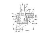
- FIG. 2 is an enlarged cross-sectional view enlarging a part of FIG. 1 (in the vicinity of the spacer 80).
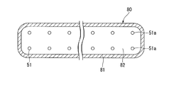
- FIG. 3 is a sectional view taken along line III-III in FIG.
- the motor 1 includes a main body 3 and a motor control device (hereinafter simply referred to as a control device) 4.
- the main body 3 mainly constitutes a drive part of the motor 1.
- the control device 4 controls the main body 3.
- the control device 4 is located above the main body 3.
- the main body 3 includes a motor housing 11, a rotor 20 having a shaft 21, a stator 30, an upper bearing (bearing) 24, a lower bearing 25, and a sensor magnet 63.
- the control device 4 includes a substrate housing 12, a bearing holder (frame member) 40, a lid 70, a spacer 80, a first substrate 66, a second substrate 67, and a plurality of connection pins (wiring) 51. And heat radiation grease (heat radiation material) G.
- the motor housing 11 and the substrate housing 12 accommodate each part (mainly the main body part 3) of the motor 1 inside.
- the motor housing 11 has a cylindrical shape that opens upward (+ Z side).
- the substrate housing 12 has a cylindrical shape that opens downward ( ⁇ Z side).
- the motor housing 11 and the substrate housing 12 are disposed with their openings facing each other. Between the motor housing 11 and the substrate housing 12, a peripheral portion of a bearing holder 40 described later is sandwiched.
- the motor housing 11 has a first cylindrical portion 14, a first bottom portion 13, and a lower bearing holding portion 18.
- the first cylindrical portion 14 has a cylindrical shape that surrounds the radially outer side of the stator 30.
- the 1st cylindrical part 14 is cylindrical, for example.
- the first cylindrical portion 14 is fitted in a stepped portion 40b provided on the periphery of the bearing holder 40 at the upper end.
- a stator 30 is fixed to the inner side surface of the first cylindrical portion 14.
- the first bottom portion 13 is provided at the lower ( ⁇ Z side) end portion of the first cylindrical portion 14.
- the first bottom portion 13 is provided with an output shaft hole portion 13a penetrating the first bottom portion 13 in the axial direction (Z-axis direction).
- the lower bearing holding portion 18 is provided on the upper (+ Z side) surface of the first bottom portion 13. The lower bearing holding portion 18 holds the lower bearing 25.
- the substrate housing 12 is located on the upper side (+ Z side) of the motor housing 11. In the present embodiment, the substrate housing 12 accommodates the first substrate 66 and the second substrate 67. An electronic component or the like is mounted on at least one of the upper surface and the lower surface of the first substrate 66 and the second substrate 67.
- the substrate housing 12 has a second cylindrical portion 15 and a second bottom portion 16.
- the second cylindrical portion 15 has a cylindrical shape surrounding the first substrate 66 and the second substrate 67 in the radial direction.
- the 2nd cylindrical part 15 is cylindrical shape, for example.
- a flange portion 15 a is provided at the lower end of the second cylindrical portion 15.
- the second cylindrical portion 15 is connected to the upper surface 40a of the bearing holder 40 at the flange portion 15a.
- the rotor 20 includes a shaft 21, a rotor core 22, and a rotor magnet 23.
- the shaft 21 has a columnar shape extending along the central axis J extending in the vertical direction (Z-axis direction).
- the shaft 21 is supported by the lower bearing 25 and the upper bearing 24 so as to be rotatable around the central axis J.
- the lower end ( ⁇ Z side) of the shaft 21 protrudes to the outside of the housing 10 through the output shaft hole 13a.
- a coupler (not shown) for connecting to an output target is press-fitted into the lower end portion of the shaft 21.
- a hole is provided in the upper end surface 21 a of the shaft 21.
- An attachment member 62 is fitted into the hole of the shaft 21.
- the attachment member 62 is a rod-like member extending in the axial direction.
- the rotor core 22 is fixed to the shaft 21.
- the rotor core 22 surrounds the shaft 21 in the circumferential direction.
- the rotor magnet 23 is fixed to the rotor core 22. More specifically, the rotor magnet 23 is fixed to the outer surface along the circumferential direction of the rotor core 22.
- the rotor core 22 and the rotor magnet 23 rotate together with the shaft 21.
- the rotor core 22 may have a through hole or a recess, and the rotor magnet 23 may be accommodated in the through hole or the recess.
- the stator 30 surrounds the outer side of the rotor 20 in the radial direction.
- the stator 30 includes a stator core 31, a bobbin 32, and a coil 33.
- the bobbin 32 is made of an insulating material.
- the bobbin 32 covers at least a part of the stator core 31.
- the coil 33 is configured by winding a conductive wire.
- the coil 33 is provided on the bobbin 32. As shown in FIG. 4 to be described later, the end portion 33a of the conductive wire constituting the coil 33 extends upward from the coil 33 and passes through the bearing holder 40 and is connected to the first substrate 66. .
- the upper bearing 24 is a ball bearing.
- the upper bearing 24 rotatably supports the upper end portion of the shaft 21.
- the upper bearing 24 is located on the upper side (+ Z side) of the stator 30.
- the upper bearing 24 is held by a bearing holder 40.
- the lower bearing 25 is a ball bearing.
- the lower bearing 25 rotatably supports the lower end portion of the shaft 21.
- the lower bearing 25 is located on the lower side ( ⁇ Z side) of the stator 30.
- the lower bearing 25 is held by the lower bearing holding portion 18 of the motor housing 11.
- the upper bearing 24 and the lower bearing 25 support the shaft 21 of the rotor 20.
- the types of the upper bearing 24 and the lower bearing 25 are not particularly limited, and other types of bearings may be used.
- the sensor magnet 63 is located above (+ Z side) the upper bearing 24.
- the sensor magnet 63 has an annular shape.
- the sensor magnet 63 is fitted on the outer surface of the mounting member 62 fixed to the shaft 21. Thereby, the sensor magnet 63 is attached to the shaft 21. Further, the sensor magnet 63 is located above the upper bearing 24. That is, the sensor magnet 63 is fixed to the shaft 21 via the mounting member 62 above the upper bearing 24 at the upper end portion of the shaft 21.
- the shape of the sensor magnet 63 is not limited to an annular shape, and may be another shape such as an annular shape or a disk shape.
- the sensor magnet 63 may be provided with a recess, and the tip of the mounting member 62 may be fixed to the recess by press-fitting or bonding. Further, the sensor magnet 63 may be directly attached to the tip of the shaft 21.
- the bearing holder 40 is located on the upper side (+ Z side) of the stator 30. In the present embodiment, the bearing holder 40 directly holds the upper bearing 24.
- the planar view (XY plane view) shape of the bearing holder 40 is, for example, a circular shape concentric with the central axis J.
- the bearing holder 40 is made of a metal material. In the present embodiment, the bearing holder 40 is sandwiched between the motor housing 11 and the substrate housing 12.
- the planar view (XY plane view) shape of the bearing holder 40 is not limited to a circular shape, and may be another shape such as a polygonal shape.
- the bearing holder 40 has an upper surface 40a facing upward.
- the upper surface 40 a faces the lower surface 66 a of the first substrate 66.
- a pair of accommodating recesses (recesses) 41 are provided on the upper surface 40a.
- the housing recess 41 is recessed downward from the upper surface 40a.
- the accommodation recess 41 opens upward on the upper surface 40a.
- the pair of receiving recesses 41 are respectively disposed along the peripheral edge of the bearing holder 40.
- the pair of housing recesses 41 are located on opposite sides of the central axis J.
- a spacer 80 is inserted into the pair of receiving recesses 41.
- the heat dissipating grease G is located between the upper surface 40a of the bearing holder 40 and the lower surface 66a of the first substrate 66.
- the heat dissipation grease G transfers heat generated in the first substrate 66 and the mounted component mounted on the first substrate 66 to the bearing holder 40.
- the bearing holder 40 radiates heat transmitted from the heat radiation grease G to the outside. That is, according to this embodiment, the bearing holder 40 can function as a heat sink.
- the bearing holder 40 is preferably made of a material having high heat conduction efficiency, and is preferably made of, for example, an aluminum alloy.
- the heat dissipating grease G preferably has insulating properties. Thereby, the thermal radiation grease can suppress discharge between the first substrate 66 and the bearing holder 40.
- the material of the bearing holder 40 may be aluminum, copper, copper alloy, SUS, or the like other than the aluminum alloy.
- the bearing holder 40 is provided with a through hole 45 penetrating in the vertical direction.
- the through hole 45 is located at the approximate center of the bearing holder 40.
- the upper end portion of the shaft 21 is disposed inside the through hole 45.
- a downward step surface 45 a is provided on the inner peripheral surface of the through-hole 45.
- the through hole 45 accommodates the upper bearing 24 in a region below the downward step surface 45a.
- the upper surface of the outer ring of the upper bearing 24 is in contact with the downward step surface 45 a through the wave washer 46.
- the upper opening of the through hole 45 is covered with a lid 70.
- the lid body 70 is fitted and fixed in the through hole 45.
- the lid 70 can suppress the heat dissipation grease G from entering the through hole 45.
- the first substrate 66 and the second substrate 67 control the motor 1.
- the motor 1 includes a control device 4 that includes a first substrate 66 and a second substrate 67 and controls the rotation of the shaft 21.
- Electronic components are mounted on the first substrate 66 and the second substrate 67.
- Electronic components mounted on the first substrate 66 and the second substrate 67 are a rotation sensor 61, an electrolytic capacitor, a choke coil, and the like.
- the first substrate 66 is disposed on the upper side (+ Z side) of the bearing holder 40.
- the second substrate 67 is disposed on the upper side of the first substrate 66.
- the plate surface directions of the first substrate 66 and the second substrate 67 are both perpendicular to the axial direction.
- the first substrate 66 and the second substrate 67 are disposed so as to overlap each other when viewed from the axial direction. That is, the first substrate 66 and the second substrate 67 are stacked with a predetermined gap along the axial direction.
- the first substrate 66 has a lower surface 66a and an upper surface 66b.
- the second substrate 67 has a lower surface 67a and an upper surface 67b.
- the upper surface 66b of the first substrate 66 and the lower surface 67a of the second substrate 67 face each other in the vertical direction with a gap therebetween.
- the lower surface 66a of the first substrate 66 and the upper surface 40a of the bearing holder 40 face each other in the vertical direction with a gap therebetween. That is, the first substrate 66 is disposed above the bearing holder 40 with a gap.
- a gap between the lower surface 66a of the first substrate 66 and the upper surface 40a of the bearing holder 40 is filled with heat radiation grease G.
- a rotation sensor 61 is mounted on the lower surface 66a of the first substrate 66.
- the rotation sensor 61 is disposed so as to overlap with the sensor magnet 63 of the first substrate 66 when viewed from the axial direction.
- the rotation sensor 61 detects the rotation of the sensor magnet 63.
- the rotation sensor 61 is a magnetoresistive element.
- the rotation sensor 61 may be another sensor such as a Hall element, for example.
- FIG. 4 is an exploded view of the motor 1.
- illustration of each mounting component mounted on the substrate housing 12, the first substrate 66, and the second substrate 67 is omitted.
- the first substrate 66 and the second substrate 67 are electrically connected by a plurality of connection pins 51.
- the first substrate 66 and the second substrate 67 constitute a substrate assembly 68.
- the first substrate 66 and the second substrate 67 are provided with a plurality of holes 66c and 67c penetrating vertically.
- the hole 66c of the first substrate 66 and the hole 67c of the second substrate 67 are arranged so as to overlap each other when viewed from the axial direction.
- the hole 66 c of the first substrate 66 and the hole 67 c of the second substrate 67 are connected by the connection pin 51.
- the control device 4 includes a first substrate 66 and a second substrate 67 that are stacked in the vertical direction (axial direction). Further, the first substrate 66 is electrically connected to the second substrate (another substrate) disposed on the upper side by the connection pins 51. According to the control device 4 of the present embodiment, the plurality of substrates (the first substrate 66 and the second substrate 67) that are electrically connected to each other are provided on each substrate according to the thermal characteristics. It is possible to select a mounting component to be mounted on the board. In the present embodiment, the first substrate 66 is in thermal contact with the bearing holder 40 having a function as a heat sink via the heat radiation grease G. Therefore, the first substrate 66 has higher heat dissipation efficiency than the second substrate 67.
- the motor 1 When mounting a mounting component that easily generates heat on the first substrate 66, the motor 1 having excellent heat dissipation characteristics as a whole can be provided. Further, a mounting component that easily generates heat may be mounted on the second substrate 67, and a mounting component that is easily affected by heat may be mounted on the first substrate 66. In this case, it is possible to make the mounting component of the first substrate 66 hardly affected by heat.
- connection pin 51 extends along the axial direction (vertical direction) between the hole 66 c of the first substrate 66 and the hole 67 c of the second substrate 67.
- the connection pin 51 has a first tip portion 51a located on the lower side and a second tip portion 51b located on the upper side.
- the first tip 51a is inserted into the hole 66c of the first substrate 66 from the upper surface 66b side and connected to the first substrate 66.
- the second tip 51 b is inserted into the hole 67 c of the second substrate 67 from the lower surface 67 a side and connected to the second substrate 67.
- the connection between the first tip 51a and the hole 66c of the first substrate 66 and the connection between the second tip 51b and the hole 67c of the second substrate 67 are so-called press-fit connections.
- the first tip 51a is slightly wider than the hole 66c.
- the first tip 51a is press-fitted into the hole 66c.
- a mechanical contact load is generated between the first tip 51a and the hole 66c and is electrically connected to each other.
- the second tip 51b is slightly wider than the hole 67c and is electrically connected to each other by a mechanical contact load.
- the first substrate 66 and the second substrate 67 are connected by press-fit connection via the connection pins 51.
- the press-fit connection it is not necessary to interpose solder between the connection pin 51 and the first substrate 66 and the second substrate 67.
- the process of press-fitting the connection pin 51 into the hole 66c (or the hole 67c) can be performed simultaneously on the plurality of connection pins 51, the process can be completed in a short time. Thereby, the manufacturing process can be simplified, the manufacturing cost can be reduced, and the inexpensive control device 4 and the motor 1 can be provided.
- the plurality of connection pins 51 are classified into a first connection pin group (first wiring group) 56A and a second connection pin group (second wiring group) 56B.
- the first connection pin group 56A and the second connection pin group 56B are located on opposite sides in the radial direction with the central axis J interposed therebetween.
- the plurality of connection pins 51 of the first connection pin group 56A and the second connection pin group 56B are arranged in a plurality of columns and rows in the vertical and horizontal directions, respectively.
- the control device 4 has two control circuits.
- the control device 4 includes two mounted components having the same function and two control circuits that connect the mounted components.
- the control apparatus 4 has increased redundancy. That is, the control device 4 can continue to drive the motor 1 by the control circuit of the other system even if some trouble occurs in the control circuit of one system.
- the first connection pin group 56A described above bears a part of one control circuit of the two systems of control circuits
- the second connection pin group 56B bears a part of the other control circuit. That is, the first substrate 66 and the second substrate 67 are electrically connected by the plurality of connection pins 51 of two systems.
- the two control circuits in the control device 4 do not necessarily have the same function as long as the motor can be driven by the other control circuit. , At least a part of the functions may be different, and it is not always necessary to have two mounting parts having the same function.
- the spacer 80 is made of an insulating material.
- the spacer 80 is interposed between the bearing holder 40 and the first substrate 66.
- the spacer 80 is inserted into the housing recess 41.
- the spacer 80 is fixed to the bearing holder 40 by means such as adhesion.
- the spacer 80 has a bottom wall portion 82, a side wall portion 81, and a flange portion 83.
- the bottom wall portion 82 and the side wall portion 81 cover the inner surface of the housing recess 41.
- the spacer 80 constitutes a box that opens upward by the bottom wall portion 82 and the side wall portion 81.
- the bottom wall portion 82 and the side wall portion 81 are covered with a spacer 80.
- the first tip portion 51a of the connection pin 51 protruding from the lower surface 66a of the first substrate 66 is accommodated. That is, the first tip 51 a protruding from the lower surface 66 a is accommodated in the accommodating recess 41 via the spacer 80.
- the bearing holder 40 is provided with a pair of receiving recesses 41, and a spacer 80 is inserted into each receiving recess 41.
- the first connection pin group 56A is inserted into one of the pair of spacers 80, and the second connection pin group 56B is connected to the other. That is, the first tip 51a of the plurality of connection pins 51 (first connection pin group 56A) constituting one system and the plurality of connection pins 51 (second connection pin group 56B) constituting the other system.
- the first tip 51a is surrounded by the side wall 81 of the spacer 80, which is different from the first tip 51a.
- the first tip 51 a protruding from the lower surface 66 a of the first substrate 66 is accommodated in the accommodating recess 41 provided on the upper surface 40 a of the bearing holder 40. Therefore, according to the present embodiment, the first tip 51a and the bearing holder 40 are separated in the vertical direction without increasing the distance between the upper surface 40a of the bearing holder 40 and the lower surface 66a of the first substrate 66. be able to. Thereby, the dimension along the up-down direction of the motor 1 provided with the control apparatus 4 and the control apparatus 4 can be made small.
- the inner surface of the accommodating recess 41 is covered with the spacer 80 made of an insulating material.
- insulating materials have better insulating properties than atmospheric air.
- the spacer 80 compared with the case where the spacer 80 is not provided, the 1st front-end
- the size of the housing recess 41 can be reduced, and as a result, the size of the control device 4 and the motor 1 including the control device 4 can be reduced.
- the bottom wall portion 82 has a substantially rectangular shape in plan view. As shown in FIG. 2, the bottom wall portion 82 is disposed along the bottom surface of the housing recess 41. A gap is provided between the bottom wall portion 82 and the accommodating recess 41. The bottom wall portion 82 is located between the first tip portion 51a of the connection pin 51 and the bearing holder 40 along the vertical direction. The bottom wall portion 82 ensures the insulating properties in the vertical direction of the first tip portion 51 a and the bearing holder 40. By providing the bottom wall portion 82, the vertical dimension of the control device 4 can be reduced.
- the side wall portion 81 extends upward from the peripheral edge of the bottom wall portion 82.
- the side wall portion 81 is disposed along the inner side surface of the housing recess 41.
- the height dimension of the side wall portion 81 is smaller than the depth dimension of the housing recess 41.
- the side wall portion 81 collectively surrounds the first tip portions 51a of the plurality of connection pins 51 in plan view.
- the side wall 81 ensures insulation between the first tip 51 a and the side wall of the housing recess 41.
- the flange portion 83 is located at the upper end of the side wall portion 81.
- the flange portion 83 is sandwiched between the bearing holder 40 and the first substrate 66. That is, the spacer 80 is in contact with the mutually opposing surfaces (the upper surface 40a and the lower surface 66a) of the bearing holder 40 and the first substrate 66 in the flange portion 83.
- the flange portion 83 determines the vertical position of the first substrate 66 with respect to the bearing holder 40.
- the height dimension of the side wall part 81 is smaller than the depth dimension of the accommodating recess 41 as described above, a gap is provided between the bottom wall part 82 and the accommodating recess 41. Therefore, by managing the thickness of the flange portion 83 with high accuracy, the first substrate 66 can be accurately positioned without strictly managing the dimension of the side wall portion 81 in the height direction.
- the flange portion 83 is arranged so as to surround the first connection pin group 56A (or the second connection pin group 56B). Further, the flange portion 83 contacts the surfaces of the bearing holder 40 and the first substrate 66 facing each other. The flange portion 83 can reduce the load on the first substrate 66 by receiving a force when the connection pin 51 is press-fitted into the hole 66 c of the first substrate 66.
- FIG. 5 is a cross-sectional view of a modified spacer 180 that can be employed in the above-described embodiment.
- 6 is a cross-sectional view taken along the line VI-VI in FIG.
- symbol is attached
- the spacer 180 has a bottom wall portion 182, a side wall portion 181, a partition wall portion 184, and a flange portion 183.
- the bottom wall portion 182 is disposed along the bottom surface of the housing recess 41.
- the side wall portion 181 extends upward from the bottom surface of the bottom wall portion 182.
- the side wall portion 181 is disposed along the inner side surface of the housing recess 41.
- the bottom wall portion 182 and the side wall portion 181 form a box that opens upward.
- the partition wall portion 184 extends upward from the bottom wall portion 182.
- the partition wall part 184 has a cross shape in plan view.
- the partition wall part 184 partitions the inside of the side wall part 181 into a plurality of regions in plan view.
- the height of the upper surface of the partition wall portion 184 matches the height of the upper surface of the flange portion 183.
- the flange portion 183 is located at the upper end of the side wall portion 181.
- the flange portion 183 is sandwiched between the bearing holder 40 and the first substrate 66.
- the first tip portion 51a of one connection pin 51 is accommodated in each of the regions partitioned by the partition wall portion 184 and the side wall portion 181.
- the partition wall portion 184 since the first tip portions 51a of the plurality of connection pins 51 are arranged in the regions partitioned by the partition wall portion 184, the insulation between the first tip portions 51a is ensured. Can do. Further, the partition wall portion 184 functions as a rib that reinforces the spacer 180. Further, the partition wall portion 184 receives a force when the connection pin 51 is press-fitted into the hole 66c of the first substrate 66, and can reduce the load on the first substrate 66 more effectively.
- the following configuration may be employed.
- the case where the first tip 51a is connected to the first substrate 66 by press-fitting using the connection pin 51 as the wiring is illustrated.
- a bent conductor may be adopted as the wiring.
- the front end portion of the wiring (corresponding to the first front end portion 51a) can be inserted into the hole 66c of the first substrate 66 from the upper surface 66b and soldered on the lower surface 66a side for connection.
- the spacer 80 is effective in ensuring insulation between the tip of the wiring and the bearing holder 40.
- connection pins 51 the case where the first substrate 66 is connected to the second substrate 67 via the connection pins 51 is illustrated.
- an external device may be connected to the first substrate 66 via a wiring (corresponding to the connection pin 51).
- the spacer 80 has the flange portion 83 having a shape along the opening periphery of the housing recess 41 has been described.
- the flange portion 83 may have an extension portion 85 extending along the circumferential direction of the central axis J, as shown in FIG.
- the extension portion 85 is sandwiched between the bearing holder 40 and the first substrate 66.
- the flange portion 83 can define a gap (vertical distance) between the bearing holder 40 and the first substrate 66 in a wide range.
- the extension portions 85 of the pair of spacers 80 disposed on opposite sides of the central axis J may be integrally connected along the circumferential direction of the central axis J.
- a through hole for inserting a screw may be provided in the extended portion 85 and screwed to the bearing holder 40 together with the first substrate 66.
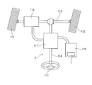
- FIG. 7 is a schematic diagram showing the electric power steering apparatus 2 of the present embodiment.
- the electric power steering device 2 is mounted on a steering mechanism of a vehicle wheel.
- the electric power steering device 2 is a device that reduces the steering force by hydraulic pressure.
- the electric power steering apparatus 2 of the present embodiment includes a motor 1, a steering shaft 114, an oil pump 116, and a control valve 117.
- the steering shaft 114 transmits the input from the steering 111 to the axle 113 having the wheels 112.
- the oil pump 116 generates hydraulic pressure in the power cylinder 115 that transmits driving force by hydraulic pressure to the axle 113.
- the control valve 117 controls the oil of the oil pump 116.
- the motor 1 is mounted as a drive source for the oil pump 116.
- the electric power steering apparatus 2 of the present embodiment includes the motor 1 of the present embodiment, the electric power steering apparatus 2 having the same effects as the motor 1 described above can be obtained.
- SYMBOLS 1 Motor, 2 ... Electric power steering apparatus, 4 ... Control apparatus (motor control apparatus), 21 ... Shaft, 24 ... Upper bearing (bearing), 40 ... Bearing holder (frame member), 41 ... Housing recessed part (recessed part), DESCRIPTION OF SYMBOLS 51 ... Connection pin (wiring), 51a ... Tip part, 66c, 67c ... Hole, 80, 180 ... Spacer, 81, 181 ... Side wall part, 82, 181, 182 ... Bottom wall part, 111 ... Steering, 184 ... Partition wall Part
Landscapes
- Engineering & Computer Science (AREA)
- Power Engineering (AREA)
- Chemical & Material Sciences (AREA)
- Combustion & Propulsion (AREA)
- Transportation (AREA)
- Mechanical Engineering (AREA)
- Microelectronics & Electronic Packaging (AREA)
- Motor Or Generator Frames (AREA)
- Power Steering Mechanism (AREA)
Abstract
金属材料からなるフレーム部材と、フレーム部材の上側に隙間を介して配置され、上下面を貫通する孔が設けられた基板と、基板の上面側から孔に挿入され基板に接続された先端部を有する配線と、フレーム部材と基板との間に介在する絶縁材料からなるスペーサと、を備え、スペーサは、平面視で配線の先端部を囲む側壁部を有する、モータ制御装置。
Description
本発明は、モータ制御装置、モータ、および電動パワーステアリング装置に関する。
制御装置を搭載したモータにおいて、電力および信号を供給する配線の先端部(コネクタ端子)を圧入により接続する構造が知られている(特許文献1)。配線の先端部は、基板の裏面側に突出する。このため、従来のモータは、配線の先端部の絶縁性を確保するため、モータの基板裏面と対向する面には、コネクタ端子の先端を収容する凹部が設けられていた。
一般的に、空気中において異なる部材同士の間で十分な絶縁を確保するためには、比較的大きな距離を必要とすることが知られている。従来の構造では、配線の先端部と凹部の壁面との距離を十分に確保するために大きな凹部を設ける必要があり、結果としてモータの寸法が大きくなるという問題があった。
本発明の一つの態様は、上記問題点に鑑みて、基板に接続された配線の先端部の絶縁性を確保しつつ小型化を図ることができるモータ制御装置、そのようなモータ制御装置を備えたモータ、およびそのようなモータを備えた電動パワーステアリング装置を提供することを目的の一つとする。
本発明のモータの一つの態様のモータ制御装置は、金属材料からなるフレーム部材と、前記フレーム部材の上側に隙間を介して配置され、上下面を貫通する孔が設けられた基板と、前記基板の上面側から前記孔に挿入され前記基板に接続された先端部を有する配線と、前記フレーム部材と前記基板との間に介在する絶縁材料からなるスペーサと、を備え、前記スペーサは、平面視で前記配線の前記先端部を囲む側壁部を有する。
本発明の一つの態様によれば、基板に接続された配線の先端部の絶縁性を確保しつつ小型化を図ることができるモータ制御装置、そのようなモータ制御装置を備えたモータ、およびそのようなモータを備えた電動パワーステアリング装置を提供される。
以下、図面を参照しながら、本発明の実施形態に係るモータについて説明する。なお、本発明の範囲は、以下の実施の形態に限定されず、本発明の技術的思想の範囲内で任意に変更可能である。また、以下の図面においては、各構成をわかりやすくするために、実際の構造と各構造における縮尺や数等を異ならせる場合がある。
また、図面においては、適宜3次元直交座標系としてXYZ座標系を示す。XYZ座標系において、Z軸方向は、図1に示す中心軸Jの軸方向と平行な方向とする。X軸方向は、Z軸方向と直交する方向であって図1の左右方向とする。Y軸方向は、X軸方向とZ軸方向との両方と直交する方向とする。
また、以下の説明においては、Z軸方向の正の側(+Z側,一方側)を「上側」と呼び、Z軸方向の負の側(-Z側,他方側)を「下側」と呼ぶ。なお、上側および下側とは、単に説明のために用いられる名称であって、実際の位置関係や方向を限定しない。また、特に断りのない限り、中心軸Jに平行な方向(Z軸方向)を単に「軸方向」と呼び、中心軸Jを中心とする径方向を単に「径方向」と呼び、中心軸Jを中心とする周方向、すなわち、中心軸Jの軸周りを単に「周方向」と呼ぶ。加えて、本明細書において、平面視とは、Z軸方向に沿って見る場合を言う。
<モータ>
図1は、本実施形態のモータ1を示す断面図である。図2は、図1の一部(スペーサ80の近傍)を拡大した拡大断面図である。また、図3は、図2のIII-III線に沿う断面図である。
図1は、本実施形態のモータ1を示す断面図である。図2は、図1の一部(スペーサ80の近傍)を拡大した拡大断面図である。また、図3は、図2のIII-III線に沿う断面図である。
モータ1は、本体部3と、モータ制御装置(以下、単に制御装置)4と、を備える。本体部3は、主にモータ1の駆動部分を構成する。制御装置4は、本体部3を制御する。制御装置4は、本体部3の上側に位置する。 本体部3は、モータハウジング11と、シャフト21を有するロータ20と、ステータ30と、上側ベアリング(ベアリング)24と、下側ベアリング25と、センサマグネット63と、を備える。 制御装置4は、基板ハウジング12と、ベアリングホルダ(フレーム部材)40と、蓋体70と、スペーサ80と、第1の基板66と、第2の基板67と、複数の接続ピン(配線)51と、放熱グリス(放熱材)Gと、を備える。
[ハウジング]
モータハウジング11および基板ハウジング12は、モータ1の各部(主に本体部3)を内部に収容する。モータハウジング11は、上側(+Z側)に開口する筒状である。また、基板ハウジング12は、下側(-Z側)に開口する筒状である。モータハウジング11と基板ハウジング12とは、互いに開口を対向させて配置されている。モータハウジング11と基板ハウジング12との間には、後述のベアリングホルダ40の周縁部が挟み込まれている。
モータハウジング11および基板ハウジング12は、モータ1の各部(主に本体部3)を内部に収容する。モータハウジング11は、上側(+Z側)に開口する筒状である。また、基板ハウジング12は、下側(-Z側)に開口する筒状である。モータハウジング11と基板ハウジング12とは、互いに開口を対向させて配置されている。モータハウジング11と基板ハウジング12との間には、後述のベアリングホルダ40の周縁部が挟み込まれている。
モータハウジング11は、第1の筒状部14と、第1の底部13と、下側ベアリング保持部18と、を有する。第1の筒状部14は、ステータ30の径方向外側を囲む筒状である。本実施形態において第1の筒状部14は、例えば、円筒状である。第1の筒状部14は、上端においてベアリングホルダ40の周縁に設けられた段差部40bに嵌め込まれている。第1の筒状部14の内側面には、ステータ30が固定されている。
第1の底部13は、第1の筒状部14の下側(-Z側)の端部に設けられている。第1の底部13には、第1の底部13を軸方向(Z軸方向)に貫通する出力軸孔部13aが設けられている。下側ベアリング保持部18は、第1の底部13の上側(+Z側)の面に設けられている。下側ベアリング保持部18は、下側ベアリング25を保持する。
基板ハウジング12は、モータハウジング11の上側に(+Z側)に位置する。本実施形態では、基板ハウジング12は、第1の基板66および第2の基板67を収容する。第1の基板66および第2の基板67の上面および下面の少なくともいずれか一方には、電子部品等が実装される。基板ハウジング12は、第2の筒状部15と、第2の底部16と、を有する。
第2の筒状部15は、第1の基板66および第2の基板67の径方向外側を囲む筒状である。第2の筒状部15は、例えば、円筒状である。第2の筒状部15の下端にはフランジ部15aが設けられている。第2の筒状部15は、フランジ部15aにおいてベアリングホルダ40の上面40aに接続されている。
[ロータ]
ロータ20は、シャフト21と、ロータコア22と、ロータマグネット23と、を有する。シャフト21は、上下方向(Z軸方向)に延びる中心軸Jに沿って延びる円柱状である。シャフト21は、下側ベアリング25と上側ベアリング24とによって、中心軸Jの軸周りに回転可能に支持されている。シャフト21の下側(-Z側)の端部は、出力軸孔部13aを介してハウジング10の外部に突出している。シャフト21の下側の端部には、例えば、出力対象に接続するためのカプラー(図示略)が圧入される。シャフト21の上端面21aには穴部が設けられている。シャフト21の穴部には、取付部材62が嵌め合わされている。取付部材62は、軸方向に延びる棒状部材である。
ロータ20は、シャフト21と、ロータコア22と、ロータマグネット23と、を有する。シャフト21は、上下方向(Z軸方向)に延びる中心軸Jに沿って延びる円柱状である。シャフト21は、下側ベアリング25と上側ベアリング24とによって、中心軸Jの軸周りに回転可能に支持されている。シャフト21の下側(-Z側)の端部は、出力軸孔部13aを介してハウジング10の外部に突出している。シャフト21の下側の端部には、例えば、出力対象に接続するためのカプラー(図示略)が圧入される。シャフト21の上端面21aには穴部が設けられている。シャフト21の穴部には、取付部材62が嵌め合わされている。取付部材62は、軸方向に延びる棒状部材である。
ロータコア22は、シャフト21に固定されている。ロータコア22は、シャフト21を周方向に囲んでいる。ロータマグネット23は、ロータコア22に固定されている。より詳細には、ロータマグネット23は、ロータコア22の周方向に沿った外側面に固定されている。ロータコア22およびロータマグネット23は、シャフト21とともに回転する。なお、ロータコア22が貫通孔または凹部を有し、当該貫通孔または凹部の内部にロータマグネット23が収容されてもよい。
[ステータ]
ステータ30は、ロータ20の径方向外側を囲んでいる。ステータ30は、ステータコア31と、ボビン32と、コイル33と、を有する。ボビン32は、絶縁性を有する材料から構成される。ボビン32は、ステータコア31の少なくとも一部を覆う。モータ1の駆動時において、コイル33は、ステータコア31を励磁する。コイル33は、導電線が巻き回されて構成される。コイル33は、ボビン32に設けられている。後段で説明する図4に示すように、コイル33を構成する導電線の端部33aは、コイル33から上側に向かって延び、ベアリングホルダ40を貫通して第1の基板66に接続されている。
ステータ30は、ロータ20の径方向外側を囲んでいる。ステータ30は、ステータコア31と、ボビン32と、コイル33と、を有する。ボビン32は、絶縁性を有する材料から構成される。ボビン32は、ステータコア31の少なくとも一部を覆う。モータ1の駆動時において、コイル33は、ステータコア31を励磁する。コイル33は、導電線が巻き回されて構成される。コイル33は、ボビン32に設けられている。後段で説明する図4に示すように、コイル33を構成する導電線の端部33aは、コイル33から上側に向かって延び、ベアリングホルダ40を貫通して第1の基板66に接続されている。
[上側ベアリングおよび下側ベアリング]
本実施形態において、上側ベアリング24は、ボールベアリングである。上側ベアリング24は、シャフト21の上端部を回転可能に支持する。上側ベアリング24は、ステータ30の上側(+Z側)に位置する。上側ベアリング24は、ベアリングホルダ40に保持されている。 本実施形態において、下側ベアリング25は、ボールベアリングである。下側ベアリング25は、シャフト21の下端部を回転可能に支持する。下側ベアリング25は、ステータ30の下側(-Z側)に位置する。下側ベアリング25は、モータハウジング11の下側ベアリング保持部18に保持されている。
本実施形態において、上側ベアリング24は、ボールベアリングである。上側ベアリング24は、シャフト21の上端部を回転可能に支持する。上側ベアリング24は、ステータ30の上側(+Z側)に位置する。上側ベアリング24は、ベアリングホルダ40に保持されている。 本実施形態において、下側ベアリング25は、ボールベアリングである。下側ベアリング25は、シャフト21の下端部を回転可能に支持する。下側ベアリング25は、ステータ30の下側(-Z側)に位置する。下側ベアリング25は、モータハウジング11の下側ベアリング保持部18に保持されている。
上側ベアリング24と下側ベアリング25とは、ロータ20のシャフト21を支持している。上側ベアリング24および下側ベアリング25の種類は、特に限定されず、他の種類のベアリングを用いてもよい。
[センサマグネット]
センサマグネット63は、上側ベアリング24よりも上側(+Z側)に位置する。センサマグネット63は、円環状である。センサマグネット63は、シャフト21に固定された取付部材62の外側面に嵌め合わされている。これにより、センサマグネット63は、シャフト21に取り付けられている。また、センサマグネット63は、上側ベアリング24より上側に位置する。すなわち、センサマグネット63は、シャフト21の上端部の上側ベアリング24の上側で取付部材62を介してシャフト21に固定されている。なお、センサマグネット63の形状は、円環状に限られず、環状や円盤状など他の形状であってもよい。この場合、センサマグネット63には、凹部が設けられ、当該凹部に取付部材62の先端が圧入や接着等によって固定されてもよい。また、センサマグネット63はシャフト21の先端に直接取り付けられてもよい。
センサマグネット63は、上側ベアリング24よりも上側(+Z側)に位置する。センサマグネット63は、円環状である。センサマグネット63は、シャフト21に固定された取付部材62の外側面に嵌め合わされている。これにより、センサマグネット63は、シャフト21に取り付けられている。また、センサマグネット63は、上側ベアリング24より上側に位置する。すなわち、センサマグネット63は、シャフト21の上端部の上側ベアリング24の上側で取付部材62を介してシャフト21に固定されている。なお、センサマグネット63の形状は、円環状に限られず、環状や円盤状など他の形状であってもよい。この場合、センサマグネット63には、凹部が設けられ、当該凹部に取付部材62の先端が圧入や接着等によって固定されてもよい。また、センサマグネット63はシャフト21の先端に直接取り付けられてもよい。
[ベアリングホルダ]
ベアリングホルダ40は、図1に示すように、ステータ30の上側(+Z側)に位置している。本実施形態では、ベアリングホルダ40は、上側ベアリング24を直接的に保持する。ベアリングホルダ40の平面視(XY面視)形状は、例えば、中心軸Jと同心の円形状である。ベアリングホルダ40は、金属材料からなる。本実施形態においてベアリングホルダ40は、モータハウジング11と基板ハウジング12との間に挟み込まれている。なお、ベアリングホルダ40の平面視(XY面視)形状は、円形状に限られず、多角形状などの他の形状であってもよい。
ベアリングホルダ40は、図1に示すように、ステータ30の上側(+Z側)に位置している。本実施形態では、ベアリングホルダ40は、上側ベアリング24を直接的に保持する。ベアリングホルダ40の平面視(XY面視)形状は、例えば、中心軸Jと同心の円形状である。ベアリングホルダ40は、金属材料からなる。本実施形態においてベアリングホルダ40は、モータハウジング11と基板ハウジング12との間に挟み込まれている。なお、ベアリングホルダ40の平面視(XY面視)形状は、円形状に限られず、多角形状などの他の形状であってもよい。
ベアリングホルダ40は、上側を向く上面40aを有する。上面40aは、第1の基板66の下面66aと対向する。上面40aには、一対の収容凹部(凹部)41が設けられている。収容凹部41は、上面40aから下側に窪む。また、収容凹部41は、上面40aにおいて上側に開口する。一対の収容凹部41は、ベアリングホルダ40の周縁部に沿ってそれぞれ配置されている。一対の収容凹部41は、中心軸Jを挟んで互いに反対側に位置する。一対の収容凹部41には、スペーサ80が挿入されている。
ベアリングホルダ40の上面40aと第1の基板66の下面66aとの間には、放熱グリスGが位置する。放熱グリスGは、第1の基板66および第1の基板66に実装された実装部品において生じた熱を、ベアリングホルダ40に伝える。ベアリングホルダ40は、放熱グリスGから伝わる熱を外部に放熱する。すなわち、本実施形態によれば、ベアリングホルダ40をヒートシンクとして機能させることができる。ベアリングホルダ40は、熱伝導効率の高い材料から構成されることが好ましく、例えばアルミニウム合金からなることが好ましい。放熱グリスGは、絶縁性を有することが好ましい。これにより、放熱グリスは、第1の基板66とベアリングホルダ40との間での放電を抑制することができる。なお、ベアリングホルダ40の材料としては、アルミニウム合金以外にも、アルミニウム、銅、銅合金、SUS等などであってもよい。
ベアリングホルダ40には、上下方向に貫通する貫通孔45が設けられている。貫通孔45は、ベアリングホルダ40の略中央に位置する。貫通孔45の内側には、シャフト21の上端部が配置される。貫通孔45の内周面には、下向き段差面45aが設けられている。貫通孔45は、下向き段差面45aより下側の領域において上側ベアリング24を収容する。下向き段差面45aには、ウェーブワッシャ46を介して上側ベアリング24の外輪の上面が接触する。また、貫通孔45の上側の開口は、蓋体70により覆われている。蓋体70は、貫通孔45に嵌合して固定されている。蓋体70は、放熱グリスGが貫通孔45内に侵入することを抑制できる。
[第1の基板、第2の基板]
第1の基板66および第2の基板67は、モータ1を制御する。すなわち、モータ1は、第1の基板66および第2の基板67から構成されシャフト21の回転を制御する制御装置4を備える。第1の基板66および第2の基板67には、電子部品が実装されている。第1の基板66および第2の基板67に実装される電子部品は、回転センサ61、電解コンデンサ、チョークコイル等である。
第1の基板66および第2の基板67は、モータ1を制御する。すなわち、モータ1は、第1の基板66および第2の基板67から構成されシャフト21の回転を制御する制御装置4を備える。第1の基板66および第2の基板67には、電子部品が実装されている。第1の基板66および第2の基板67に実装される電子部品は、回転センサ61、電解コンデンサ、チョークコイル等である。
第1の基板66は、ベアリングホルダ40の上側(+Z側)に配置されている。第2の基板67は、第1の基板66の上側に配置されている。第1の基板66および第2の基板67の板面方向は、ともに軸方向に対して垂直である。第1の基板66および第2の基板67は、軸方向からみて互いに重なり合って配置されている。すなわち、第1の基板66および第2の基板67は、軸方向に沿って所定の隙間を介し積層されている。
第1の基板66は、下面66aと上面66bとを有する。同様に、第2の基板67は、下面67aと上面67bとを有する。第1の基板66の上面66bと第2の基板67の下面67aは、隙間を介して上下方向に対向している。また、第1の基板66の下面66aとベアリングホルダ40の上面40aは、隙間を介して上下方向に対向する。すなわち、第1の基板66は、ベアリングホルダ40の上側に隙間を介して配置されている。第1の基板66の下面66aとベアリングホルダ40の上面40aとの間の隙間には、放熱グリスGが充填されている。
第1の基板66の下面66aには、回転センサ61が実装されている。また、回転センサ61は、軸方向から見て、第1の基板66のセンサマグネット63と重なるように配置されている。回転センサ61は、センサマグネット63の回転を検出する。本実施形態において回転センサ61は、磁気抵抗素子である。回転センサ61は、例えば、ホール素子など他のセンサであってもよい。
図4は、モータ1の分解図である。図4において、基板ハウジング12および第1の基板66および第2の基板67に実装される各実装部品の図示を省略する。 図4に示すように、第1の基板66と第2の基板67とは、複数の接続ピン51により電気的に接続されている。第1の基板66と第2の基板67とは、基板アセンブリ68を構成する。
図1に示すように、第1の基板66および第2の基板67には、それぞれ上下方向に貫通する複数の孔66c、67cが設けられている。第1の基板66の孔66cと第2の基板67の孔67cとは、軸方向からみて互いに重なりあって配置されている。第1の基板66の孔66cと、第2の基板67の孔67cとは、接続ピン51によって接続される。
制御装置4は、上下方向(軸方向)に沿って積層された第1の基板66および第2の基板67を有する。また、第1の基板66は、上側に配置された第2の基板(他の基板)と接続ピン51により電気的に接続されている。本実施形態の制御装置4によれば、互いに電気的に接続された複数の基板(第1の基板66および第2の基板67)を有することで、熱的な特性に応じて、各基板上に実装される実装部品を選択することができる。本実施形態において、第1の基板66は、放熱グリスGを介してヒートシンクとしての機能を備えたベアリングホルダ40と熱的に接触する。したがって、第1の基板66は、第2の基板67と比較して放熱効率が高い。第1の基板66に熱を発しやすい実装部品を実装する場合には、全体として放熱特性に優れたモータ1を提供できる。また、第2の基板67に熱を発しやすい実装部品を実装するとともに、第1の基板66に熱に影響を受けやすい実装部品してもよい。この場合には、第1の基板66の実装部品に熱の影響を与え難くすることができる。
[接続ピン(配線)]
接続ピン51は、図1に示すように、第1の基板66の孔66cと第2の基板67の孔67cとの間で軸方向(上下方向)に沿って延びている。接続ピン51は、下側に位置する第1の先端部51aと、上側に位置する第2の先端部51bと、を有する。第1の先端部51aは、上面66b側から第1の基板66の孔66cに挿入され第1の基板66に接続されている。また、第2の先端部51bは、下面67a側から第2の基板67の孔67cに挿入され第2の基板67に接続されている。
接続ピン51は、図1に示すように、第1の基板66の孔66cと第2の基板67の孔67cとの間で軸方向(上下方向)に沿って延びている。接続ピン51は、下側に位置する第1の先端部51aと、上側に位置する第2の先端部51bと、を有する。第1の先端部51aは、上面66b側から第1の基板66の孔66cに挿入され第1の基板66に接続されている。また、第2の先端部51bは、下面67a側から第2の基板67の孔67cに挿入され第2の基板67に接続されている。
第1の先端部51aと第1の基板66の孔66cとの接続および第2の先端部51bと第2の基板67の孔67cとの接続は、いわゆるプレスフィット接続である。 第1の先端部51aは、孔66cより若干幅広である。第1の先端部51aは、孔66cに圧入される。これにより、第1の先端部51aと孔66cとの間には、機械的な接触荷重が発生し、互いに電気的に接続されている。同様に、第2の先端部51bは、孔67cより若干幅広であり、機械的な接触荷重により互いに電気的に接続されている。
本実施形態によれば、第1の基板66と第2の基板67とは、接続ピン51を介したプレスフィット接続により接続されている。プレスフィット接続を採用する場合、接続ピン51と第1の基板66および第2の基板67との間に、半田を介する必要がない。また、接続ピン51を孔66c(又は孔67c)へ圧入する工程を、複数の接続ピン51に対して同時に行うことができるため、短時間で完了することができる。これにより、製造工程を簡略化でき、製造コストを低減して安価な制御装置4およびモータ1を提供できる。
図4に示すように、複数の接続ピン51は、第1の接続ピン群(第1の配線群)56Aと第2の接続ピン群(第2の配線群)56Bとに分類される。第1の接続ピン群56Aと、第2の接続ピン群56Bは、中心軸Jを挟んで互いに径方向の反対側に位置する。第1の接続ピン群56Aおよび第2の接続ピン群56Bの複数の接続ピン51は、それぞれ縦横に複数列複数行をなして並んでいる。
本実施形態の制御装置4は、2系統等の制御回路を有する。本実施形態では、制御装置4は、同じ機能を奏する2つの実装部品および各実装部品を繋ぐ2つの制御回路が構成されている。これにより、制御装置4は、冗長性が高められている。すなわち、制御装置4は、一方の系統の制御回路に何らかの不具合が生じた場合であっても、他方の系統の制御回路によりモータ1の駆動を継続することができる。上述した、第1の接続ピン群56Aは、2系統の制御回路のうち一方の制御回路の一部を担い、第2の接続ピン群56Bは、他方の制御回路の一部を担う。すなわち、第1の基板66および第2の基板67は、2系統の複数の接続ピン51により電気的に接続されている。なお、一方の系統の制御回路等が故障したとしても他方の制御回路によってモータを駆動可能であるならば、制御装置4における2つの制御回路は、必ずしも同じ機能を有しなくてもよく、互いに、機能の少なくとも一部が異なっていてもよく、必ずしも同じ機能を奏する2つの実装部品を有していなくてもよい。
[スペーサ]
スペーサ80は、絶縁材料からなる。スペーサ80は、ベアリングホルダ40と第1の基板66との間に介在する。スペーサ80は、収容凹部41内に挿入される。スペーサ80は、接着などの手段によりベアリングホルダ40に固定されている。
スペーサ80は、絶縁材料からなる。スペーサ80は、ベアリングホルダ40と第1の基板66との間に介在する。スペーサ80は、収容凹部41内に挿入される。スペーサ80は、接着などの手段によりベアリングホルダ40に固定されている。
図2に示すように、スペーサ80は、底壁部82と、側壁部81と、フランジ部83と、を有する。底壁部82および側壁部81は、収容凹部41の内面を覆う。また、スペーサ80は、底壁部82および側壁部81により上側に開口する箱体を構成する。底壁部82および側壁部81は、スペーサ80により覆われる。スペーサ80の内側には、第1の基板66の下面66aから突出した接続ピン51の第1の先端部51aが収容される。すなわち、下面66aから突出した第1の先端部51aは、スペーサ80を介して収容凹部41に収容されている。
図4に示すように、ベアリングホルダ40には、一対の収容凹部41が設けられ、それぞれの収容凹部41にスペーサ80が挿入されている。また、第1の接続ピン群56Aは、一対のスペーサ80のうち一方に挿入され、第2の接続ピン群56Bは、他方に接続されている。すなわち、一方の系統を構成する複数の接続ピン51(第1の接続ピン群56A)の第1の先端部51aと、他方の系統を構成する複数の接続ピン51(第2の接続ピン群56B)の第1の先端部51aとは、それぞれ異なるスペーサ80の側壁部81に囲まれて配置されている。
図2に示すように、本実施形態によれば、ベアリングホルダ40の上面40aに設けられた収容凹部41に第1の基板66の下面66aから突出した第1の先端部51aが収容される。したがって、本実施形態によれば、ベアリングホルダ40の上面40aと第1の基板66の下面66aとの距離を離すことなく第1の先端部51aとベアリングホルダ40とを上下方向に沿って離間させることができる。これにより、制御装置4および制御装置4を備えたモータ1の上下方向に沿う寸法を小さくすることができる。
本実施形態によれば、収容凹部41の内面が絶縁材料からなるスペーサ80に覆われている。一般的に絶縁材料は、大気圧の空気より絶縁特性に優れる。このため、スペーサ80を設けることによって、スペーサ80を設けない場合と比較して、絶縁性を確保しつつ第1の先端部51aと収容凹部41の内面とを近づけることができる。上下方向および上下方向に直交する方向において、収容凹部41の寸法を小さくすることができ、結果として制御装置4および制御装置4を備えたモータ1の寸法を小さくすることができる。
底壁部82は、平面視略矩形状を有する。また、図2に示すように、底壁部82は、収容凹部41の底面に沿って配置されている。底壁部82と収容凹部41との間には、隙間が設けられている。底壁部82は、上下方向に沿って、接続ピン51の第1の先端部51aとベアリングホルダ40の間に位置する。底壁部82は、第1の先端部51aとベアリングホルダ40の上下方向の絶縁性を確保する。底壁部82が設けられていることによって、制御装置4の上下寸法を小さくできる。
側壁部81は、底壁部82の周縁から上方に延びる。側壁部81は、収容凹部41の内側面に沿って配置されている。側壁部81の高さ寸法は、収容凹部41の深さ寸法より小さい。側壁部81は、平面視で複数の接続ピン51の第1の先端部51aを纏めて囲む。側壁部81は、第1の先端部51aと収容凹部41の側壁部との絶縁性を確保する。側壁部81が設けられていることによって、制御装置4の上下方向と直交する方向の寸法(径方向寸法)を小さくできる。
フランジ部83は、側壁部81の上端に位置する。フランジ部83は、ベアリングホルダ40と第1の基板66との間に挟み込まれる。すなわち、スペーサ80は、フランジ部83において、ベアリングホルダ40および第1の基板66の互いに対向する面(上面40aおよび下面66a)にそれぞれ接触する。
フランジ部83は、ベアリングホルダ40に対する第1の基板66の上下方向の位置を決める。なお、上述したように側壁部81の高さ寸法が収容凹部41の深さ寸法より小さいため、底壁部82と収容凹部41との間には隙間が設けられる。したがって、フランジ部83の厚さを高精度に管理することで、側壁部81の高さ方向の寸法管理を厳密に行うことなく、第1の基板66の位置決めを精密に行うことができる。
フランジ部83は、第1の接続ピン群56A(又は第2の接続ピン群56B)を囲むように配置されている。また、フランジ部83は、ベアリングホルダ40および第1の基板66の互いに対向する面と接触する。フランジ部83は、第1の基板66の孔66cに対して接続ピン51を圧入する際の力を受けて、第1の基板66への負荷を軽減できる。
<変形例>
図5は、上述の実施形態に採用可能な変形例のスペーサ180の断面図である。また、図6は、図5のVI-VI線に沿う断面図である。なお、上述の実施形態と同一態様の構成要素については、同一符号を付し、その説明を省略する。
図5は、上述の実施形態に採用可能な変形例のスペーサ180の断面図である。また、図6は、図5のVI-VI線に沿う断面図である。なお、上述の実施形態と同一態様の構成要素については、同一符号を付し、その説明を省略する。
スペーサ180は、底壁部182と、側壁部181と、区画壁部184と、フランジ部183と、を有する。底壁部182は、収容凹部41の底面に沿って配置されている。側壁部181は、底壁部182の底面から上方に延びる。側壁部181は、収容凹部41の内側面に沿って配置されている。底壁部182および側壁部181により上側に開口する箱体を構成する。区画壁部184は、底壁部182から上方に延びる。区画壁部184は、平面視で十字形状を有する。区画壁部184は、平面視で側壁部181の内側を複数の領域に区画する。区画壁部184の上面の高さは、フランジ部183の上面の高さと一致する。フランジ部183は、側壁部181の上端に位置する。フランジ部183は、ベアリングホルダ40と第1の基板66との間に挟み込まれる。
図6に示すように、区画壁部184と側壁部181で区画された領域には、それぞれ1つの接続ピン51の第1の先端部51aが収容される。
本変形例によれば、複数の接続ピン51の第1の先端部51aが互いに区画壁部184で区画された領域に配置されるため、第1の先端部51a同士の絶縁性を確保することができる。また、区画壁部184は、スペーサ180を補強するリブとして機能する。また、区画壁部184は、第1の基板66の孔66cに対して接続ピン51を圧入する際の力を受けて、第1の基板66への負荷をより効果的に軽減できる。
<その他の変形例>
本実施形態においては、下記の構成を採用してもよい。 本実施形態では、配線として接続ピン51を用いて第1の先端部51aを第1の基板66に圧入により接続する場合を例示した。しかしながら、配線として、屈曲する導線を採用してもよい。この場合、配線の先端部(第1の先端部51aに相当)を第1の基板66の孔66cに上面66bから挿入するとともに、下面66a側で半田付けして接続することができる。この場合であっても、スペーサ80は、配線の先端部とベアリングホルダ40との絶縁性確保に効果を奏する。
本実施形態においては、下記の構成を採用してもよい。 本実施形態では、配線として接続ピン51を用いて第1の先端部51aを第1の基板66に圧入により接続する場合を例示した。しかしながら、配線として、屈曲する導線を採用してもよい。この場合、配線の先端部(第1の先端部51aに相当)を第1の基板66の孔66cに上面66bから挿入するとともに、下面66a側で半田付けして接続することができる。この場合であっても、スペーサ80は、配線の先端部とベアリングホルダ40との絶縁性確保に効果を奏する。
本実施形態では、第1の基板66には、接続ピン51を介して第2の基板67に接続される場合を例示した。しかしながら、第1の基板66には、配線(接続ピン51に相当)を介して外部の装置が接続されていていてもよい。
本実施形態では、スペーサ80が、収容凹部41の開口周縁に沿った形状のフランジ部83を有する場合について説明した。しかしながら、フランジ部83は、図4に示すように、中心軸Jの周方向に沿って延びる拡張部85を有していてもよい。拡張部85は、ベアリングホルダ40と第1の基板66との間に挟み込まれる。拡張部85が設けられている場合に、フランジ部83は、ベアリングホルダ40と第1の基板66との隙間(上下方向の距離)を広範囲で規定することができる。なお、中心軸Jを挟んで互いに反対側に配置された一対のスペーサ80の拡張部85は、中心軸Jの周方向に沿って一体的に繋がっていてもよい。また、拡張部85にネジを挿入する貫通孔を設けて、第1の基板66とともにベアリングホルダ40にネジ止めしてもよい。
<電動パワーステアリング装置>
次に、本実施形態のモータ1を搭載する装置の実施形態について説明する。本実施形態においては、モータ1を電動パワーステアリング装置に搭載した例について説明する。図7は、本実施形態の電動パワーステアリング装置2を示す模式図である。
次に、本実施形態のモータ1を搭載する装置の実施形態について説明する。本実施形態においては、モータ1を電動パワーステアリング装置に搭載した例について説明する。図7は、本実施形態の電動パワーステアリング装置2を示す模式図である。
電動パワーステアリング装置2は、自動車の車輪の操舵機構に搭載される。電動パワーステアリング装置2は、操舵力を油圧により軽減する装置である。図7に示すように、本実施形態の電動パワーステアリング装置2は、モータ1と、操舵軸114と、オイルポンプ116と、コントロールバルブ117と、を備える。
操舵軸114は、ステアリング111からの入力を、車輪112を有する車軸113に伝える。オイルポンプ116は、車軸113に油圧による駆動力を伝えるパワーシリンダ115に油圧を発生させる。コントロールバルブ117は、オイルポンプ116のオイルを制御する。電動パワーステアリング装置2において、モータ1は、オイルポンプ116の駆動源として搭載されている。
本実施形態の電動パワーステアリング装置2は、本実施形態のモータ1を備えるため、上述のモータ1と同様の効果を奏する電動パワーステアリング装置2が得られる。
以上に、本発明の実施形態および変形例を説明したが、実施形態における各構成およびそれらの組み合わせ等は一例であり、本発明の趣旨から逸脱しない範囲内で、構成の付加、省略、置換およびその他の変更が可能である。また、本発明は実施形態によって限定されることはない。
1…モータ、2…電動パワーステアリング装置、4…制御装置(モータ制御装置)、21…シャフト、24…上側ベアリング(ベアリング)、40…ベアリングホルダ(フレーム部材)、41…収容凹部(凹部)、51…接続ピン(配線)、51a…先端部、66c,67c…孔、80,180…スペーサ、81,181…側壁部、82,181,182…底壁部、111…ステアリング、184…区画壁部
Claims (13)
- 金属材料からなるフレーム部材と、
前記フレーム部材の上側に隙間を介して配置され、上下面を貫通する孔が設けられた基板と、
前記基板の上面側から前記孔に挿入され前記基板に接続された先端部を有する配線と、
前記フレーム部材と前記基板との間に介在する絶縁材料からなるスペーサと、を備え、
前記スペーサは、平面視で前記配線の前記先端部を囲む側壁部を有する、モータ制御装置。 - 前記スペーサは、前記フレーム部材および前記基板の互いに対向する面にそれぞれ接触する、請求項1に記載のモータ制御装置。
- 前記スペーサは、前記配線の先端部と前記フレーム部材との間に位置する底壁部を有する、請求項1又は2に記載のモータ制御装置。
- 前記基板には、複数の前記配線の先端部が接続され、
前記スペーサは、平面視で前記側壁部の内側を複数の領域に区画する区画壁部を有し、
前記区画壁部で区画された各領域に前記先端部が位置する、請求項1~3の何れか一項に記載のモータ制御装置。 - 前記区画壁が、平面視で十字形状を有する、請求項4に記載のモータ制御装置。
- 前記フレーム部材の前記基板と対向する面に凹部が設けられ、
前記スペーサは、前記凹部に挿入されている、請求項1~5の何れか一項に記載のモータ制御装置。 - 前記配線の先端部は、前記基板の前記孔より幅広であり、機械的な接触荷重により互いに電気的に接続されている、請求項1~6の何れか一項に記載のモータ制御装置。
- 前記基板は、上側に配置された他の基板と前記配線により電気的に接続されている、請求項1~7の何れか一項に記載のモータ制御装置。
- 2つの前記基板は、2系統の複数の前記配線により互いに接続されている、
一方の系統を構成する複数の配線の先端部と、他方の系統を構成する複数の配線の先端部は、それぞれ異なるスペーサの側壁部に囲まれている、請求項8に記載のモータ制御装置。 - 請求項1~9の何れか一項に記載のモータ制御装置を備えた、モータ。
- 回転するシャフトと、
前記シャフトの一端部を支持するベアリングと、を備え、
前記フレーム部材が、前記ベアリングを保持する、請求項10に記載のモータ。 - 前記フレーム部材が、前記基板で発生した熱を外部に放熱するヒートシンクとして機能する、請求項10又は11に記載のモータ。
- 請求項10~12の何れか一項に記載のモータを有する電動パワーステアリング装置。
Priority Applications (4)
| Application Number | Priority Date | Filing Date | Title |
|---|---|---|---|
| DE112017004952.0T DE112017004952T5 (de) | 2016-09-30 | 2017-09-22 | Motorsteuervorrichtung, Motor und elektrische Servolenkvorrichtung |
| CN201780058119.6A CN109716632B (zh) | 2016-09-30 | 2017-09-22 | 马达控制装置、马达以及电动助力转向装置 |
| US16/337,417 US10919564B2 (en) | 2016-09-30 | 2017-09-22 | Motor control device, motor, and electric power steering device |
| JP2018542497A JP6969566B2 (ja) | 2016-09-30 | 2017-09-22 | モータ制御装置、モータ、および電動パワーステアリング装置 |
Applications Claiming Priority (2)
| Application Number | Priority Date | Filing Date | Title |
|---|---|---|---|
| JP2016-193881 | 2016-09-30 | ||
| JP2016193881 | 2016-09-30 |
Publications (1)
| Publication Number | Publication Date |
|---|---|
| WO2018062004A1 true WO2018062004A1 (ja) | 2018-04-05 |
Family
ID=61759727
Family Applications (1)
| Application Number | Title | Priority Date | Filing Date |
|---|---|---|---|
| PCT/JP2017/034192 Ceased WO2018062004A1 (ja) | 2016-09-30 | 2017-09-22 | モータ制御装置、モータ、および電動パワーステアリング装置 |
Country Status (5)
| Country | Link |
|---|---|
| US (1) | US10919564B2 (ja) |
| JP (1) | JP6969566B2 (ja) |
| CN (1) | CN109716632B (ja) |
| DE (1) | DE112017004952T5 (ja) |
| WO (1) | WO2018062004A1 (ja) |
Cited By (3)
| Publication number | Priority date | Publication date | Assignee | Title |
|---|---|---|---|---|
| DE102018221765A1 (de) * | 2018-12-14 | 2020-06-18 | Robert Bosch Gmbh | Gehäuse für eine elektrische Maschine |
| JP2023082812A (ja) * | 2021-12-03 | 2023-06-15 | 住友重機械工業株式会社 | アクチュエータ、アクチュエータ装置、ロボット及びアクチュエータ装置のシリーズ |
| WO2024134806A1 (ja) * | 2022-12-21 | 2024-06-27 | 株式会社ジェイテクト | モータ装置 |
Families Citing this family (2)
| Publication number | Priority date | Publication date | Assignee | Title |
|---|---|---|---|---|
| JP7211259B2 (ja) * | 2019-05-17 | 2023-01-24 | 株式会社デンソー | 駆動装置 |
| CN115411890A (zh) * | 2022-09-20 | 2022-11-29 | 胡建 | 一种汽车转向模拟器结构 |
Citations (6)
| Publication number | Priority date | Publication date | Assignee | Title |
|---|---|---|---|---|
| JPS60141147A (ja) * | 1983-12-28 | 1985-07-26 | Toshiba Corp | 制御装置内蔵形回転電機 |
| JP2007306671A (ja) * | 2006-05-09 | 2007-11-22 | Denso Corp | 車両用のモータ駆動装置 |
| JP2010062467A (ja) * | 2008-09-05 | 2010-03-18 | Tdk Corp | インバータトランスの取付構造 |
| JP2015144507A (ja) * | 2014-01-31 | 2015-08-06 | 株式会社デンソー | 駆動装置 |
| JP2016025814A (ja) * | 2014-07-24 | 2016-02-08 | 株式会社安川電機 | 回転電機 |
| JP2016127780A (ja) * | 2015-01-08 | 2016-07-11 | 株式会社デンソー | 駆動装置 |
Family Cites Families (5)
| Publication number | Priority date | Publication date | Assignee | Title |
|---|---|---|---|---|
| WO1997033359A1 (en) * | 1996-03-07 | 1997-09-12 | Seiko Epson Corporation | Motor and process for producing the same |
| EP1363026A3 (en) * | 2002-04-26 | 2004-09-01 | Denso Corporation | Invertor integrated motor for an automotive vehicle |
| JP4343100B2 (ja) * | 2004-12-28 | 2009-10-14 | 日本電産株式会社 | モータユニットおよび記録ディスク駆動装置 |
| JP4385058B2 (ja) * | 2007-05-07 | 2009-12-16 | 三菱電機株式会社 | 電子制御装置 |
| JP6248984B2 (ja) * | 2014-07-31 | 2017-12-20 | 株式会社デンソー | 駆動装置 |
-
2017
- 2017-09-22 DE DE112017004952.0T patent/DE112017004952T5/de not_active Withdrawn
- 2017-09-22 US US16/337,417 patent/US10919564B2/en not_active Expired - Fee Related
- 2017-09-22 WO PCT/JP2017/034192 patent/WO2018062004A1/ja not_active Ceased
- 2017-09-22 JP JP2018542497A patent/JP6969566B2/ja not_active Expired - Fee Related
- 2017-09-22 CN CN201780058119.6A patent/CN109716632B/zh active Active
Patent Citations (6)
| Publication number | Priority date | Publication date | Assignee | Title |
|---|---|---|---|---|
| JPS60141147A (ja) * | 1983-12-28 | 1985-07-26 | Toshiba Corp | 制御装置内蔵形回転電機 |
| JP2007306671A (ja) * | 2006-05-09 | 2007-11-22 | Denso Corp | 車両用のモータ駆動装置 |
| JP2010062467A (ja) * | 2008-09-05 | 2010-03-18 | Tdk Corp | インバータトランスの取付構造 |
| JP2015144507A (ja) * | 2014-01-31 | 2015-08-06 | 株式会社デンソー | 駆動装置 |
| JP2016025814A (ja) * | 2014-07-24 | 2016-02-08 | 株式会社安川電機 | 回転電機 |
| JP2016127780A (ja) * | 2015-01-08 | 2016-07-11 | 株式会社デンソー | 駆動装置 |
Cited By (5)
| Publication number | Priority date | Publication date | Assignee | Title |
|---|---|---|---|---|
| DE102018221765A1 (de) * | 2018-12-14 | 2020-06-18 | Robert Bosch Gmbh | Gehäuse für eine elektrische Maschine |
| JP2023082812A (ja) * | 2021-12-03 | 2023-06-15 | 住友重機械工業株式会社 | アクチュエータ、アクチュエータ装置、ロボット及びアクチュエータ装置のシリーズ |
| JP7748267B2 (ja) | 2021-12-03 | 2025-10-02 | 住友重機械工業株式会社 | アクチュエータ装置及びロボット |
| US12515315B2 (en) | 2021-12-03 | 2026-01-06 | Sumitomo Heavy Industries, Ltd. | Actuator, actuator device, robot, and series of actuator devices |
| WO2024134806A1 (ja) * | 2022-12-21 | 2024-06-27 | 株式会社ジェイテクト | モータ装置 |
Also Published As
| Publication number | Publication date |
|---|---|
| US10919564B2 (en) | 2021-02-16 |
| JP6969566B2 (ja) | 2021-11-24 |
| US20190232999A1 (en) | 2019-08-01 |
| CN109716632B (zh) | 2021-01-15 |
| DE112017004952T5 (de) | 2019-06-13 |
| JPWO2018062004A1 (ja) | 2019-08-15 |
| CN109716632A (zh) | 2019-05-03 |
Similar Documents
| Publication | Publication Date | Title |
|---|---|---|
| CN109716632B (zh) | 马达控制装置、马达以及电动助力转向装置 | |
| US11292507B2 (en) | Motor and electric power steering device | |
| US20190077440A1 (en) | Motor and electric power steering device | |
| US11177715B2 (en) | Motor | |
| CN109792192B (zh) | 马达和电动助力转向装置 | |
| US20190313549A1 (en) | Motor and electric power steering device | |
| US20180115224A1 (en) | Motor | |
| US11634168B2 (en) | Motor including connector and connector pin and electric power steering device including same | |
| US20190267862A1 (en) | Motor and electric power steering device | |
| WO2018159471A1 (ja) | ポンプ装置 | |
| WO2019244487A1 (ja) | モータ | |
| CN109716631B (zh) | 马达和电动助力转向装置 | |
| CN111033977B (zh) | 马达和电动助力转向装置 | |
| JP2017184541A (ja) | モータ | |
| WO2019198517A1 (ja) | モータ、およびポンプ装置 | |
| JP2009207277A (ja) | 小型モータ | |
| US12283860B2 (en) | Motor | |
| US12620865B2 (en) | Circuit connection apparatus, electric rotating machine apparatus and manufacturing method for circuit connection apparatus | |
| WO2023007598A1 (ja) | 回路接続装置、回転電機装置、及び回路接続装置の製造方法 | |
| WO2023007599A1 (ja) | 回路接続装置、回転電機装置、及び回路接続装置の製造方法 |
Legal Events
| Date | Code | Title | Description |
|---|---|---|---|
| 121 | Ep: the epo has been informed by wipo that ep was designated in this application |
Ref document number: 17855958 Country of ref document: EP Kind code of ref document: A1 |
|
| ENP | Entry into the national phase |
Ref document number: 2018542497 Country of ref document: JP Kind code of ref document: A |
|
| 122 | Ep: pct application non-entry in european phase |
Ref document number: 17855958 Country of ref document: EP Kind code of ref document: A1 |