WO2018055708A1 - リニアコンベア装置 - Google Patents
リニアコンベア装置 Download PDFInfo
- Publication number
- WO2018055708A1 WO2018055708A1 PCT/JP2016/077899 JP2016077899W WO2018055708A1 WO 2018055708 A1 WO2018055708 A1 WO 2018055708A1 JP 2016077899 W JP2016077899 W JP 2016077899W WO 2018055708 A1 WO2018055708 A1 WO 2018055708A1
- Authority
- WO
- WIPO (PCT)
- Prior art keywords
- module
- linear conveyor
- linear
- base frame
- receiving hole
- Prior art date
- Legal status (The legal status is an assumption and is not a legal conclusion. Google has not performed a legal analysis and makes no representation as to the accuracy of the status listed.)
- Ceased
Links
Images










Classifications
-
- B—PERFORMING OPERATIONS; TRANSPORTING
- B65—CONVEYING; PACKING; STORING; HANDLING THIN OR FILAMENTARY MATERIAL
- B65G—TRANSPORT OR STORAGE DEVICES, e.g. CONVEYORS FOR LOADING OR TIPPING, SHOP CONVEYOR SYSTEMS OR PNEUMATIC TUBE CONVEYORS
- B65G54/00—Non-mechanical conveyors not otherwise provided for
- B65G54/02—Non-mechanical conveyors not otherwise provided for electrostatic, electric, or magnetic
-
- H—ELECTRICITY
- H02—GENERATION; CONVERSION OR DISTRIBUTION OF ELECTRIC POWER
- H02K—DYNAMO-ELECTRIC MACHINES
- H02K41/00—Propulsion systems in which a rigid body is moved along a path due to dynamo-electric interaction between the body and a magnetic field travelling along the path
- H02K41/02—Linear motors; Sectional motors
-
- H—ELECTRICITY
- H02—GENERATION; CONVERSION OR DISTRIBUTION OF ELECTRIC POWER
- H02K—DYNAMO-ELECTRIC MACHINES
- H02K41/00—Propulsion systems in which a rigid body is moved along a path due to dynamo-electric interaction between the body and a magnetic field travelling along the path
- H02K41/02—Linear motors; Sectional motors
- H02K41/03—Synchronous motors; Motors moving step by step; Reluctance motors
- H02K41/031—Synchronous motors; Motors moving step by step; Reluctance motors of the permanent magnet type
-
- B—PERFORMING OPERATIONS; TRANSPORTING
- B65—CONVEYING; PACKING; STORING; HANDLING THIN OR FILAMENTARY MATERIAL
- B65G—TRANSPORT OR STORAGE DEVICES, e.g. CONVEYORS FOR LOADING OR TIPPING, SHOP CONVEYOR SYSTEMS OR PNEUMATIC TUBE CONVEYORS
- B65G2811/00—Indexing codes relating to common features for more than one conveyor kind or type
- B65G2811/09—Driving means for the conveyors
-
- B—PERFORMING OPERATIONS; TRANSPORTING
- B65—CONVEYING; PACKING; STORING; HANDLING THIN OR FILAMENTARY MATERIAL
- B65G—TRANSPORT OR STORAGE DEVICES, e.g. CONVEYORS FOR LOADING OR TIPPING, SHOP CONVEYOR SYSTEMS OR PNEUMATIC TUBE CONVEYORS
- B65G9/00—Apparatus for assisting manual handling having suspended load-carriers movable by hand or gravity
- B65G9/008—Rails or switches
Definitions
- the present invention relates to a linear conveyor apparatus having a linear motor movable element and a stator.
- a linear conveyor uses a linear motor as a drive source and moves a slider linearly along a guide rail.
- the guide rail is assembled to a base frame on which a linear motor stator is mounted, and the linear motor movable element is attached to the slider.
- the linear motor stator is an electromagnet disposed in parallel with the guide rail, and the linear motor movable element is a permanent magnet. Propulsive force is given to the slider by energizing the electromagnet.
- the linear conveyor includes a linear scale including a magnetic scale mounted on the slider and a magnetic sensor installed on the base frame. The slider is moved to a desired position by controlling the energization of the electromagnet based on the position detection result by the linear scale (see, for example, Patent Document 1).
- the conveyance path length required for the linear conveyor varies depending on the user. In some cases, once the linear conveyor is laid, it is required to change the transport path length. Accordingly, it is desirable to modularize the stator side of the linear conveyor and connect the modules in series to construct a linear conveyor having a required transport path length.
- a base frame having a predetermined length, a guide rail, an electromagnet, and a magnetic sensor are provided in each module, and energization control of the electromagnet is performed in module units.
- the linear conveyor (module) is installed on a stand prepared by the user. That is, the base frame that supports the guide rails and the like is directly laid on the frame.
- the modules can be connected with high accuracy. It becomes difficult.
- An object of the present invention is to provide a linear conveyor device capable of easily and highly accurately connecting linear conveyor modules.
- a linear conveyor apparatus is a linear conveyor apparatus installed on a predetermined installation surface, and guides the movement of the linear motor stator, a slider having a linear motor movable element, and the slider.
- a linear transport unit in which a plurality of modules each having a top surface having a guide portion and a bottom surface facing the installation surface are linearly connected to each other, and the installation surface and the lower surface of the module at a connection portion between the modules And a base member that positions and supports the module.
- FIG. 1 is a perspective view schematically showing an overall configuration of a linear conveyor apparatus according to an embodiment of the present invention.
- FIG. 2 is an exploded perspective view of the linear transport unit (module connection body) and slider of the linear conveyor device.
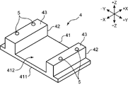
- FIG. 3 is a perspective view of a base member that supports the module on the gantry.
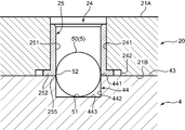
- FIG. 4A is a cross-sectional view of the connecting portion of the module in the Y direction. 4B is an enlarged cross-sectional view of a main part of FIG. 4A.
- FIG. 5A is a cross-sectional view of the connecting portion of the module in the X direction. 5B is an enlarged cross-sectional view of a main part of FIG. 5A.
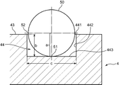
- FIG. 6 is a cross-sectional view for explaining the relationship between a ball as an example of a hemispherical protrusion serving as a positioning member and its holding hole.
- FIG. 7 is a cross-sectional view showing the ball receiving hole.
- FIG. 8A is a cross-sectional view showing a modification of the hemispherical protrusion.
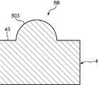
- FIG. 8B is a cross-sectional view showing a modification of the hemispherical protrusion.
- FIG. 9A is a cross-sectional view showing a modification of the receiving hole.
- FIG. 9B is a cross-sectional view showing a modification of the receiving hole.
- FIG. 10 is a schematic cross-sectional view showing a fitted state of the base member to the base frame in the present embodiment.
- FIG. 11 is a schematic cross-sectional view showing a fitting state of the base member to the base frame in the comparative example.
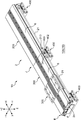
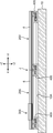
- FIG. 12 is a perspective view showing an embodiment of a linear conveyor device using a module with a cover member.
- FIG. 13 is a side view of the linear conveyor device of FIG.
- FIG. 14 is a cross-sectional view in the Y direction at the connecting portion of the module with a cover member.
- FIG. 15 is a perspective view showing an assembly example of the module.
- FIG. 1 is a perspective view schematically showing an overall configuration of a linear conveyor device 1 according to an embodiment of the present invention.
- XYZ direction indications are attached, where the X direction is the left-right direction (+ X is right, -X is left), the Y direction is the front-rear direction (+ Y is front, -Y is back), Z The direction corresponds to the vertical direction (+ Z is up, -Z is down).
- direction indications along this are also attached.
- the linear conveyor apparatus 1 is installed on a gantry 10 and has a pair of linear conveyance units 2 (first linear conveyance unit 2A and second linear conveyance unit 2B) extending in the X direction, and the ⁇ X side and + X of the linear conveyance unit 2
- the first direction changing portion 2C and the second direction changing portion 2D that are respectively located at the side ends, the slider 3 that moves along the linear conveying portion 2, and the base member 4 that supports the linear conveying portion 2 on the gantry 10 It has.
- the linear conveyance unit 2 includes a first linear conveyance unit 2A disposed on the + Y side of the gantry 10 and a second linear conveyance unit 2B disposed on the ⁇ Y side in parallel with the first linear conveyance unit 2A.
- the first and second direction changing sections 2C and 2D communicate between these linear transport sections 2A and 2B at the ⁇ X side and + X side ends.
- the gantry 10 includes an upper surface 10 ⁇ / b> A (installation surface) that is a laying surface of the linear conveyor device 1. It is basically desirable that the upper surface 10A is a surface with high flatness. However, in this embodiment, since the linear conveyor device 1 is laid using the base member 4, even if the flatness of the upper surface 10A is somewhat low, a small step is present, or the gantry 10 is divided. Even in the case where there is a seam on the upper surface 10A, these are not particularly serious problems.
- 2nd linear conveyance part 2A, 2B is a conveyance part which moves the slider 3 to a X direction.
- the first and second direction changing units 2C and 2D are conveying units that move the slider 3 in the Y direction, and the slider 3 is replaced between the first and second linear conveying units 2A and 2B. Play the role of doing.
- the first and second linear transport units 2A and 2B are units on the fixed side of the linear motor, and the slider 3 is a unit on the movable side.
- the first and second linear transport units 2A and 2B are formed by connecting a plurality of modules 20 having the guide function of the slider 3 linearly.
- the module 20 is a unit block on the fixed side that forms the slider 3 and the linear motor, and is a short linear block having a length of about 0.2 m to 1.0 m.
- the module 20 (base frame 21 described later) has an upper surface 21A and a lower surface 21B facing the gantry 10, and is supported by the base member 4 with the lower surface 21B floating from the upper surface 10A of the gantry 10. .
- the upper surface 21A is an upper surface in the sense that it is opposite to the lower surface 21B facing the gantry 10, and does not mean that the upper surface 21A is always directed upward in the actual installation mode of the module 20.
- FIG. 1 shows an example in which the first linear transport unit 2A is formed of modules 20A, 20B, 20C, 20D, and 20E that are sequentially connected in the -X to + X direction.
- the module 20D is shorter than the others is shown.
- the second linear conveyance unit 2B The same applies to the second linear conveyance unit 2B.
- the X-direction moving length of the slider 3 can be freely set by the number of modules 20 connected and the combination of modules 20 having different lengths.
- 1st, 2nd direction change part 2C, 2D contains the slide rail 11 and the module 20Y for conversion.
- the slide rail 11 is laid on the upper surface 10A of the gantry 10 so as to extend in the Y direction.
- the conversion module 20Y is engaged with the slide rail 11 so as to be movable in the Y direction along the slide rail 11.
- the conversion module 20Y is moved between the terminal end E of the first linear transport unit 2A and the terminal end E of the second linear transport unit 2B, and positioning with respect to the terminal end E is stopped by an unillustrated drive mechanism.
- the slider 3 can move around the circuit path formed on the gantry 10 by the first and second linear transport units 2A and 2B and the first and second direction changing units 2C and 2D.
- FIG. 1 shows an example in which four sliders 3A, 3B, 3C, and 3D are arranged in the circulation path and rotate in the slider movement direction F in a clockwise direction.
- the slider 3 moves from the + X side of the first linear transport unit 2A toward the ⁇ X side (there may be temporarily sent back to the + X side), and from the ⁇ X terminal end E to the first direction changing unit. Transfer to 2C conversion module 20Y. With the slider 3 mounted, the conversion module 20Y is moved in the ⁇ Y direction from the first linear conveyance unit 2A toward the second linear conveyance unit 2B.
- the slider 3 moves from the ⁇ X end E to the second linear transport unit 2B and moves to the + X side. And it transfers to the module 20Y for conversion of 2nd direction change part 2D, is moved to + Y direction, and changes to 2 A of 1st linear conveyance parts again.
- various robots are provided along the circulation path of the slider 3 to perform transfer of a workpiece such as a substrate, mounting of an electronic component or the like on the substrate, and the like.
- the upper surface of the slider 3 serves as a placement portion for the workpiece or the like.
- the slider 3 is stopped at the work position of the robot responsible for one process and moved toward the work position of the robot responsible for the next process after the work, so that the first and second linear transport units 2A, Moved on 2B.
- the base member 4 is disposed between the mount 10 and the lower surface 21B of the module 20 at the connecting portion J between the modules 20, and positions and supports the pair of modules 20 to be connected. Furthermore, the base member 4 is also arranged at the terminal end E of the first and second linear transport units 2A and 2B. Conventionally, the module 20 is directly attached to the gantry 10. However, in this embodiment, the base member 4 is interposed between the module 20 and the gantry 10, and the modules 20 connected to each other using the base member 4 are connected to each other. It is characterized in that it is positioned.
- FIG. 2 is an exploded perspective view of the linear transport unit 2 (the connected body of the modules 20) and the slider 3.
- Each module 20 includes a base frame 21, a linear motor stator 22, and a pair of guide rails 23 (guide portions).
- the slider 3 includes a slider frame 31, a linear motor movable element 32, and a pair of guide blocks 33.
- the base frame 21 is a frame made of a metal such as aluminum, and is a flat plate member that constitutes the upper surface 21A and the lower surface 21B of the module 20 described above.
- the upper surface 21A is a surface on which the linear motor stator 22 and the guide rail 23 are mounted.
- the lower surface 21B is a surface facing the upper surface 10A of the gantry 10 with a predetermined interval.
- the linear motor stator 22 is composed of an array of a plurality of electromagnets. That is, the linear motor stator 22 is formed by arranging a plurality of unit electromagnets including a core and a coil wound around the core in a line in the X direction.
- the pair of guide rails 23 are members that guide the movement of the slider 3.
- Each guide rail 23 is attached to the upper surface 21A at the Y-direction end 211 (width direction) of the base frame 21 to form two tracks extending in the X direction.
- the unit guide rails 23 of the base frames 21 can be connected to each other to form a guide rail 23 extending infinitely long. is there.
- the slider frame 31 is made of a metal block such as aluminum, has a top surface serving as a mounting portion for the workpiece, and has a shape that can be fitted into the base frame 21 from the end portion 212 in the X direction.
- the linear motor movable element 32 includes a plurality of permanent magnets arranged in the X direction and a back yoke that holds these permanent magnets.
- the linear motor movable element 32 is attached to the lower surface of the slider frame 31 at a position facing the linear motor stator 22.
- the plurality of permanent magnets are arranged so that N poles and S poles appear alternately on the surface facing the linear motor stator 22.
- the pair of guide blocks 33 are attached to the lower surface of the slider frame 31 at positions facing the pair of guide rails 23 respectively.
- the guide block 33 includes a bearing that rolls in contact with the guide rail 23, is engaged with the guide rail 23, is guided by the guide rail 23, and moves in the X direction.
- the linear motor movable element 32 forms a linear motor with the linear motor stator 22 on the base frame 21 side.
- a motor controller (not shown) supplies a current of any one of the U phase, V phase, and W phase having different phases to the linear motor stator 22 (coil of the electromagnet). Thereby, a magnetic driving force is generated by the interaction between the magnetic flux generated in the coil and the magnetic flux of the permanent magnet provided in the linear motor movable element 32, and the slider 3 is moved by this driving force.
- the pair of guide blocks 33 constitutes a pair of guide rails 23 and a linear guide.
- the slider 3 receiving the propulsive force advances straight in the X direction along the guide rail 23.
- a magnetic sensor is disposed on the upper surface 21 ⁇ / b> A of the base frame 21, and a magnetic scale is attached to the lower surface of the slider 3. These magnetic sensor and magnetic scale form a linear scale for detecting the position of the slider 3. Based on the position detection result of the slider 3 by the linear scale, the slider 3 is moved to the target position by controlling the energization of the coil of the electromagnet.
- FIG. 3 is a perspective view of the base member 4 alone.
- the base member 4 is formed of a metal block having excellent rigidity, such as aluminum, and includes a flat bottom plate 41 and a pair of ridges 42 that are erected near both ends in the Y direction of the bottom plate 41 and extend in the X direction. Yes.
- the bottom surface 411 of the bottom plate 41 abuts on the top surface 10 ⁇ / b> A of the gantry 10.
- a space between the pair of ridges 42 is a storage space 412, which can be used as a space for storing a connector for the module 20, a power supply device, and the like.
- the upper surface of the pair of ridges 42 is a support surface 43 serving as a mating surface with the lower surface 21B of the base frame 21.
- the support surface 43 supports the X direction end part 212 of a pair of module 20 (base frame 21) connected from below.
- Four hemispherical protrusions 5 protrude from the support surface 43.
- the hemispherical protrusion 5 is a member for positioning the pair of modules 20.
- the base frame 21 has a receiving hole 24 into which the hemispherical protrusion 5 is fitted.
- the receiving hole 24 is a through hole is shown for ease of processing.
- the receiving hole 24 only needs to be recessed at least on the lower surface 21 ⁇ / b> B of the base frame 21.
- various shapes of protrusions may be used as positioning members.
- FIG. 4A is a cross-sectional view in the Y direction of the connecting portion J between the modules 20, and FIG. 4B is an enlarged cross-sectional view of the main part of FIG. 4A.
- 5A is a cross-sectional view of the connecting portion J in the X direction
- FIG. 5B is an enlarged cross-sectional view of the main part of FIG. 5A.
- the hemispherical protrusion 5 shown in FIG. 3 is formed by a ball 50 made of a steel ball.
- the support surface 43 is provided with a holding hole 44 that is recessed to face the receiving hole 24 of the base frame 21.
- the ball 50 is accommodated in the holding hole 44 so that at least the upper half protrudes.
- the hemispherical protrusion 5 is formed by the upper half of the ball 50 accommodated in the holding hole 44.
- the ball 50 is in line contact with the receiving hole 24 (a part of the module) in a state where the lower surface 21B and the support surface 43 are in contact with each other.
- two (plural) balls 50 are arranged in the width direction (Y direction) of the module 20. That is, the receiving hole 24 is formed in each of the + Y and ⁇ Y end portions 211 of the base frame 21.
- the holding holes 44 are also recessed in the pair of ridges 42 (support surfaces 43) at positions corresponding to the pair of receiving holes 24 in the Y direction.
- the balls 50 are fitted into the pairs of the + Y and ⁇ Y receiving holes 24 and the holding holes 44, respectively. That is, one module 20 is positioned by two balls 50 in the Y direction. This stabilizes the positioning in the Y direction.
- two (a plurality) of balls 50 are also arranged in the moving direction (X direction) of the slider 3. That is, the holding holes 44 are respectively provided in the ⁇ X side and the + X side as viewed from the center of the ridge 42 in the X direction.
- the receiving holes 24 of the base frames 21 of the pair of modules 20 to be connected are fitted into the two balls 50 and positioned.
- the ⁇ X side is the first module 20A
- the + X side is the second module 20B.
- the end surface of the + X side end portion 212A of the first module 20A and the end surface of the ⁇ X side end portion 212B of the second module 20B are brought into contact with each other.
- the base member 4 has the support surface 43 straddling the lower surfaces of the first and second base frames 210A and 210B of the first and second modules 20A and 20B.
- FIG. 5A shows an example in which the end surfaces of both modules 20A and 20B abut each other at the center of the ridge 42 in the X direction.
- the first base frame 210A has a first receiving hole 24A at the + X side end portion 212A
- the second base frame 210B has a second receiving hole 24B at the ⁇ X side end portion 212B.
- the ball 50A held in the holding hole 44 on the ⁇ X side of the base member 4 is fitted in the first receiving hole 24A
- the ball 50B held in the holding hole 44 on the + X side is fitted in the second receiving hole 24B. It is inserted.
- three or more balls 50 and receiving holes 24 may be arranged in the X direction.
- the first module 20A is positioned on the base member 4 by fitting the first receiving hole 24A and the ball 50A
- the second module 20B is formed between the second receiving hole 24B and the ball 50B.
- the base member 4 is positioned by fitting. And as a result of these positioning, the connection part J of 1st, 2nd module 20A, 20B is formed. Therefore, the first and second modules 20A and 20B can be coupled with high accuracy by accurately managing the flatness of the support surface 43 and the positional relationship between the plurality of balls 50 in the base member 4.
- the receiving hole 24 and the holding hole 44 can be formed by cutting.
- the cutting hole is applied from the + Z side so that the receiving hole 24 and the holding hole 44 are processed once. It is desirable to drill with.
- the distance d between the pair of cores of the receiving hole 24 and the holding hole 44 on the -Y side and the core of the pair of the receiving hole 24 and the holding hole 44 on the + Y side is highly accurate (the error is about 10 ⁇ m).
- the following processing is preferably performed so as to ensure the following. The same applies to the distance between the pair of the receiving hole 24 and the holding hole 44 in the X direction.
- the positioning of the guide rail 23 is preferably based on the position of the holding hole 44, that is, the position of the ball 50.
- the guide rail 23 is attached to the upper surface 21 ⁇ / b> A of the Y direction end portion 211 of the base frame 21.
- a contact surface 233 with which the lower side of the guide rail 23 abuts is formed by step processing.
- the guide rail 23 is positioned by coming into contact with the contact surface 233 and is fixed to the base frame 21 by a fixing screw 231 and a screw hole 232 that is recessed in the upper surface 21A.
- the step processing of the contact surface 233 is formed by a series of processing following the perforation processing of the receiving hole 24 and the holding hole 44, the position of the contact surface 233 can be set with respect to the ball 50 with high accuracy. Therefore, the guide rail 23 can be positioned with respect to the ball 50 with high accuracy.
- the connecting portion J in which the pair of modules 20 are positioned with high accuracy can be constructed. That is, the position of the guide rail 23 is determined by the position of the ball 50 of the base member 4. For this reason, if the positional relationship between the plurality of balls 50 is high accuracy, the receiving holes 24 of the pair of modules 20 to be connected to the balls 50 of the base member 4 prepared corresponding to the receiving holes 24. By simply fitting the guide rails 23, the guide rails 23 can be connected with high accuracy.
- FIG. 6 is a cross-sectional view for explaining the relationship between the ball 50 and the holding hole 44
- FIG. 7 is a cross-sectional view showing the receiving hole 24.
- the holding hole 44 having a depth b slightly shorter than the radius a of the ball 50 and the receiving hole 24 in which the bush 25 (cylindrical member) is closely fitted are illustrated.
- the ball 50 for example, a steel ball such as a martensitic stainless sphere or a carbon sphere having a diameter of about 3 mm to 15 mm can be used.
- the sphericity of the ball 50 is desirably high, and it is desirable to use a ball having a grade of about 28 (tolerance ⁇ 0.5 ⁇ m).
- the holding hole 44 is a hole with a bottom that has a circular horizontal cross section and opens to the support surface 43. That is, the holding hole 44 includes a circular opening edge 441 that defines an opening on the support surface 43, a cylindrical wall surface 442 that extends vertically downward from the opening edge 441, and a bottom surface 443 that partitions the bottom of the cylindrical wall surface 442. ing.
- the opening edge 441 is an edge (about C0.02 or less) that does not substantially have a chamfered structure.
- the cylindrical wall surface 442 is a wall surface that defines a cavity that accommodates the ball 50.
- the bottom surface 443 is a flat surface that is not processed such as a recess for centering.
- the depth b from the opening edge 441 to the bottom surface 443 of the holding hole 44 is set to be slightly shorter than the radius a of the ball 50.
- it is desirable to set b a ⁇ 0.03 mm.
- the portion of the maximum circumscribed circle of the ball 50 is exposed outside the hole. Since the bottom surface 443 is a flat surface, the portion of the maximum circumscribed circle is slightly smaller than the opening edge 441 of the holding hole 44 simply by accommodating the ball 50 in the holding hole 44 and bringing the ball lower portion 51 into contact with the bottom surface 443. Can be projected.
- the location of the maximum circumscribed circle is the contact portion 52 that makes a line contact with the receiving hole 24 in the ball 50.
- the diameter c of the holding hole 44 As described above, it is possible to meet the demands of both the inhibition of the movement of the ball 50 and the insertion property to the holding hole 44. Further, as described above, by substantially not chamfering the opening edge 441, the diameter c of the holding hole 44 can be prevented from being varied.
- the ball 50 may remain in a state in which it can be rolled into the holding hole 44, but it is desirable to fix it using an adhesive or the like. For example, it is possible to put the ball 50 into a fixed state by potting an adhesive in the holding hole 44 in advance and then fitting the ball 50 into the holding hole 44 and curing the adhesive. As a result, the ball 50 can be prevented from falling off the holding hole 44.
- the bush 25 is a cylindrical member formed of a member having higher hardness than the base frame 21 (aluminum). That is, the bush 25 has such a strength that it does not deform even when it comes into contact with the ball 50. For example, it is desirable to use a bush 25 made of high hardness steel having a hardness of HRC 55 class or higher.
- the receiving hole 24 is a hole having a circular horizontal cross section, and includes a hole body 241 and a large-diameter portion 242 connected to the lower end of the hole body 24.
- the large diameter portion 242 has a diameter that is about 1.4 times larger than the diameter of the hole body 241.
- the bush 25 has a cylindrical portion 251 and a flange portion 252 provided continuously with the lower end of the cylindrical portion 251.
- the outer peripheral surface of the cylindrical portion 251 is closely joined to the inner peripheral surface of the hole body 241.
- the flange portion 252 is accommodated in the large diameter portion 242.
- the actual opening edge of the receiving hole 24 is the opening edge 255 of the bush 25. As shown in FIG.
- the upper end edge 253 of the cylindrical portion 251 is at a position slightly lower than the upper surface 21 ⁇ / b> A of the base frame 21.
- the lower end surface of the flange portion 252 is flush with the lower surface 21 ⁇ / b> B of the base frame 21.
- the opening edge 255 located at the lower end of the bush 25 is formed by the ball 50. It becomes a part which carries out a line contact with the base of the hemispherical protrusion currently performed. Strictly speaking, the contact portion 52, which is the location of the maximum circumscribed circle of the ball 50 projecting slightly upward from the support surface 43, and the location slightly above the opening edge 255 of the cylindrical portion 251 are in line contact. Become. If chamfering is performed on the opening edge 255, the hole diameter of the receiving hole 24 (bush 25) may vary at the position of the opening edge 255 due to processing errors. In this case, good line contact may not be formed, and the base frame 21 may be rattled. Therefore, the opening edge 255 of the bush 25 is an edge (about C0.02 or less) that does not substantially have a chamfered structure.
- [Modification of hemispherical protrusion and receiving hole] 8A and 8B are cross-sectional views showing modifications of the hemispherical protrusion 5 protruding from the support surface 43 of the base member 4.
- the hemispherical protrusion 5A shown in FIG. 8A is formed of a bullet-type pin.
- the hemispherical protrusion 5 ⁇ / b> A is a pin whose upper half is a hemispherical portion 501 and whose lower half is a cylindrical portion 502.
- the cylindrical portion 502 is accommodated in the holding hole 44 of the base member 4, and the hemispherical portion 501 protrudes from the support surface 43.
- the hemispherical protrusion 5B shown in FIG. 8B is formed by projecting a hemispherical convex portion 503 integral with the base member 4 on the support surface 43.
- Hemispherical protrusion 5A, 5B as shown to FIG. 8A and FIG. 8B is also employable.
- the hemispherical protrusion 5 is formed by the ball 50 accommodated in the holding hole 44 so that the upper half protrudes.
- balls with extremely high sphericity, the above-mentioned 28 grade balls can be obtained from the market easily and at low cost.
- machining the hemispherical portion at one end of the cylindrical pin as in the hemispherical projection 5A in FIG. 8A or forming the hemispherical projection 5B in FIG. 8B by cutting causes an increase in cost.
- by using the hemispherical protrusion 5 using the ball 50 it is possible to reduce the cost while providing high accuracy.
- FIG. 9A and 9B are cross-sectional views showing modifications of the receiving hole 24.
- FIG. 9A illustrates a receiving hole 24A in which the bush 25 is not fitted.
- the ball 50 and the holding hole 44 are the same as the example shown in FIGS. 4A to 6.
- the receiving hole 24A is a cylindrical hole that penetrates the base frame 21 in the vertical direction.
- the opening edge at the lower end of the receiving hole 24 ⁇ / b> A is in line contact with the maximum circumscribed circle of the ball 50.
- the base frame 21 has sufficient hardness, such a receiving hole 24A can be employed.
- FIG. 9A illustrates a receiving hole 24B having a tapered shape.
- the receiving hole 24B is a tapered hole having a large diameter opening 241B on the lower surface 21B side and a small diameter opening 242B on the upper surface 21A side, and the diameter gradually decreases from the lower surface 21B side to the upper surface 21A side.
- the diameter of the large diameter opening 241 ⁇ / b> B is larger than the diameter of the holding hole 44 and the diameter of the ball 50, and the diameter of the small diameter opening 242 ⁇ / b> B is smaller than the diameter of the ball 50.
- the inner peripheral surface located slightly above the diameter opening 241B is in line contact with the outer peripheral surface of the ball 50 (not the place of the maximum circumscribed circle).
- a small-diameter opening 242B is not provided, and a truncated cone-shaped bottomed hole may be used.
- the module 20 of the linear transport unit 2 is not directly laid on the gantry 10, but the connecting portion J between the modules 20 is supported by the base member 4 from below. Laid in a manner. Due to the interposition of the base member 4, the mutual alignment of the modules 20 to be connected can be made dependent on the base member 4. That is, instead of directly connecting the modules 20 or the guide rails 23, the connection of the pair of modules 20 can be achieved as a result by positioning and attaching the modules 20 to be connected to the base member 4. it can.
- the processing accuracy of the base member 4 that is, the positioning accuracy of the positioning member (the hemispherical protrusion 5; the ball 50 in the above embodiment) is increased, the connection accuracy between the modules 20 can be improved. Therefore, it becomes easy to manage the alignment of the connected modules 20. Further, since the base member 4 is interposed, the modules 20 can be connected without being affected by the state of the upper surface 10A of the gantry 10. Therefore, the modules 20 can be easily connected with high accuracy.
- the positioning member includes the hemispherical projection 5, and a part of the base frame 21 and the hemisphere are in contact with the lower surface 21 ⁇ / b> B of the module 20 (base frame 21) and the support surface 43 of the base member 4.
- the protrusion 5 is in line contact. More specifically, the contact portion 52 (base portion) that is the location of the maximum circumscribed circle of the ball 50 is in line contact with the opening edge 255 of the receiving hole 24 (bush 25) of the base frame 21.
- the module 20 is positioned with minimal contact.
- Such a positioning mode can suppress squeezing (Jam; receiving hole 24 and a member inserted into receiving hole 24 interfere with each other) when assembling base frame 21 to base member 4.
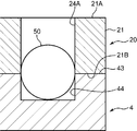
- FIG. 10 is a schematic cross-sectional view showing a fitting state of the base frame 21 to the base member 4 in this embodiment
- FIG. 11 is a schematic cross-sectional view showing a comparative example for this. If the positioning member is the ball 50 (the hemispherical protrusion 5) as in the present embodiment, the base frame 21 should come into contact with the support surface 43 of the base member 4 as shown in FIG. Even in this case, since the ball 50 invites the receiving hole 24, no scouring occurs.
- the positioning member is the ball 50 (the hemispherical protrusion 5) as in the present embodiment
- the processing tolerance of the installation position of the balls 50 can be reduced. Can be absorbed.
- the installation pitch error of the two balls 50 is 10 ⁇ m
- the base frame 21 having the receiving holes 24 that fit into the two balls 50 is fitted into the two balls 50.
- the base frame 21 is centered by the balls 50, and the installation error of the base frame 21 can be suppressed to 5 ⁇ m, which is half of 10 ⁇ m.
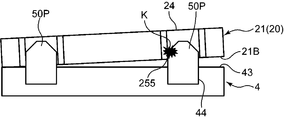
- the knock pin 50 ⁇ / b> P is a cylindrical pin whose upper end is tapered, and is installed so that its cylindrical body protrudes upward from the holding hole 44.
- the outer peripheral surface of the cylindrical body portion and the inner peripheral surface of the receiving hole 24 are in surface contact.
- galling K is likely to occur between the knock pin 50P and the receiving hole 24.
- a squeeze K in which the opening edge 255 of the receiving hole 24 abuts against the cylindrical body portion is generated.
- ⁇ To prevent galling K it is necessary to install the base frame 21 on the base member 4 without tilting, but such work is difficult. Further, if there is an error in the installation position of the knock pin 50P, the squeeze K may occur even if the base frame 21 is not inclined. For this reason, play is required for fitting the knock pin 50P and the receiving hole 24, and it is difficult to construct a highly accurate connecting portion J. If the knock pin 50P and the receiving hole 24 are to be closely fitted, the receiving hole 24 may be deformed by a frictional force such as twisting K. When the receiving hole 24 is deformed, the connection accuracy of the module 20 is naturally reduced.
- the present embodiment when the lower surface 21B of the base frame 21 and the support surface 43 of the base member 4 are brought into contact with each other, the tangled contact surface and the poor positional accuracy of the ball 50 Even when a frictional force is generated due to the above, the upper hemisphere of the ball 50 attracts the receiving hole 24, so that the receiving hole 24 is hardly deformed.
- the receiving hole 24 is formed by fitting the high-hardness bush 25, deformation is less likely to occur. For this reason, the connection accuracy is hardly lowered, and the connection accuracy of the module 20 is good.
- the opening edge 255 of the receiving hole 24 is an edge that does not substantially have a chamfered structure. If the opening edge 255 is chamfered, the hole diameter of the receiving hole 24 may vary. On the other hand, even if the opening edge 255 is not chamfered, the ball 50 invites the receiving hole 24, so that the fitting of both can be performed smoothly. In the comparative example of FIG. 11, it is almost essential to chamfer the opening edge 255. However, according to the present embodiment, the chamfering is unnecessary.
- FIG. 12 is a perspective view showing an embodiment of a linear conveyor device 1A according to another embodiment
- FIG. 13 is a side view thereof
- the linear transport unit 2 of the linear conveyor device 1 ⁇ / b> A is configured by a connected body of modules 200 with cover members 6.
- the slider 300 is movably attached to the linear conveyance unit 2 in a mode of being fitted to the cover member 6.
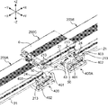
- the module 200 is supported by the base member 400 at the connecting portion J and the end portion E of the linear transport portion 2.
- the base member 400 is disposed between the gantry 10 and the lower surface 21B of the module 200, and positions and supports each module 200.
- the linear conveyor apparatus 1A has a linear motor L1, a linear guide L2, and a linear scale L3 as shown in FIG.
- the linear motor L1 includes a linear motor stator 22 and a linear motor movable element 32.
- the linear guide L2 includes a pair of guide rails 23 and a pair of guide blocks 33.
- the linear scale L3 includes a magnetic sensor unit 26 and a magnetic scale 34.
- the module 200 includes a base frame 21 on which a linear motor stator 22, a pair of guide rails 23, and a magnetic sensor unit 26 are mounted.
- the pair of guide rails 23 extend in the X direction in parallel to each other, and are disposed near the ⁇ Y end and the + Y end of the base frame 21.
- a linear motor stator 22 ( ⁇ Y side) and a magnetic sensor unit 26 (+ Y side) are disposed between the pair of guide rails 23.
- the linear motor stator 22 includes a plurality of electromagnets arranged in the X direction.
- a plurality of magnetic sensor units 26 are also arranged in the X direction.
- the cover member 6 is attached to the upper surface 21A so as to cover the upper surface 21A of the base frame 21.
- the cover member 6 includes a support leg 61, a horizontal cover portion 62, and a pair of side cover portions 63, and is a member having a substantially T-shaped cross section in the Y direction.
- the support leg 61 is erected in the center region in the Y direction of the base frame 21.
- the horizontal cover portion 62 extends horizontally from the upper end of the support leg 61 to the ⁇ Y side and the + Y side.
- the pair of side cover parts 63 extend downward from the ⁇ Y side and + Y side ends of the horizontal cover part 62.
- the horizontal cover portion 62 covers the linear motor stator 22 attached to the upper surface 21A of the base frame 21, the pair of guide rails 23, and the magnetic sensor unit 26, and the side cover portion 63 covers these sides. ing.
- the cover member 6 can prevent contamination and foreign matter from entering the upper surface 21A.
- the slider 300 includes a top plate 301 that is a horizontal plate on which a workpiece is loaded, a pair of side plates 302 that extend downward from the ⁇ Y side and + Y side ends of the top plate 301, and a width from the lower ends of the pair of side plates 302.
- a slider frame 31 having a pair of lower plates 303 extending toward the center in the direction is provided.
- the upper plate 301, the side plate 302, and the lower plate 303 form a fitting portion 30 that is fitted to the cover member 6.
- the fitting portion 30 defines a cavity that receives the cover member 6.
- the guide blocks 33 are attached to the lower surfaces of the pair of lower plates 303, respectively.
- the linear motor movable element 32 is attached to the inner end surface of the lower plate 303 on the ⁇ Y side, and the magnetic scale 34 is attached to the inner end surface of the lower plate 303 on the + Y side.
- the linear motor movable element 32 includes a plurality of permanent magnets arranged in the X direction and a back yoke for holding them.
- the magnetic scale 34 includes permanent magnets arranged on the surface facing the magnetic sensor unit 26 so that N poles and S poles appear alternately.
- the guide block 33 is engaged with the guide rail 23 and is guided by the guide rail 23 to move in the X direction.
- the inner peripheral surface of the fitting portion 30 and the outer peripheral surface of the cover member 6 face each other with a gap of a predetermined width.
- the linear motor movable element 32 faces the linear motor stator 22, and the magnetic scale 34 also faces the magnetic sensor unit 26.
- FIG. 15 is a perspective view showing an assembly example of the module 200, and a part of the upper surface portion of the base member 400 is shown.
- the base member 400 includes a bottom plate 41, ridges 42, and a support surface 43, and balls 50 as hemispherical protrusions are disposed on the support surface 43.
- the bottom surface 411 of the bottom plate 41 is in contact with the upper surface 10A of the gantry 10, and the support surface 43 supports the lower surface 21B of the base frame 21 at the connecting portion J between the modules 200.
- the mounting of the module 200 to the base member 400 so that the receiving hole 24 of the base frame 21 fits into the ball 50 enables positioning of the pair of modules 200 to be connected to each other. It is the same as the form.
- the base member 400 includes a first fixing portion 401 formed of a screw hole drilled in the support surface 43 in the vertical direction, and a first hole formed of a through hole drilled in the vertical direction at the ⁇ Y side and + Y side ends of the bottom plate 41. 2 fixing part 402.
- the first fixing portion 401 is a screw hole for detachably fixing each module 200 to the base member 400.
- a mounting hole 213 provided in the base frame 21 is superimposed on the first fixing portion 401, and the fixing screw 403 is screwed into and released from the first fixing portion 401, so that the module 200 is a base member. 400 is attached and detached.
- the second fixing portion 402 is a hole for detachably fixing the base member 400 to the gantry 10.
- the second fixing portion 402 is aligned with a bolt hole (not shown) drilled in the upper surface 10A and fastened to the gantry 10 with a bolt (not shown).
- a bolt hole not shown
- the module 200 can be freely attached to and detached from the base member 400, and the base member 400 can be attached to and detached from the mount 10, and the user can easily add, insert, and replace the module 200. ing.
- FIG. 15 illustrates a case where a short third module 200C is inserted between the first module 200A and the second module 200B. If the connecting portion of the first and second modules 200A and 200B is supported by the first base member 400, a second base member 400A is newly added. In this case, the second module 200B is removed from the first base member 400 and shifted in the + X direction by the length of the third module 200C.
- the second base member 400 ⁇ / b> A is fixed to the gantry 10 at the second fixing portion 402 with a pitch corresponding to the length of the third module 200 ⁇ / b> C with respect to the first base member 400.
- the second module 200B is attached to the support surface 43 on the + X side of the second base member 400A.
- the + X side support surface 43 of the first base member 400 and the ⁇ X side support surface 43 of the second base member 400A serve as the support surface of the third module 200C.
- the third module 200C includes the first and second X-side and + X-side receiving holes 24 included in the base module 21 of the third module 200C so as to fit into the balls 50 carried on the respective support surfaces 43. 2 Mounted on the base members 400 and 400A. Thereafter, the fixing screw 403 is screwed into the first fixing portion 401 through the attachment hole 213, whereby the insertion operation of the third module 200C is completed.
- the third module 200C can be inserted by a simple operation.
- the linear conveyor apparatus 1 can take various modified embodiments.
- the predetermined installation surface was the upper surface 10A extended in the horizontal direction of the mount frame 10, and the linear conveyor apparatus 1 was shown on the upper surface 10A.
- the linear conveyor device 1 may be attached to the installation surface extending in the vertical direction by a wall-hanging method, for example, by erecting the gantry 10 vertically.
- the linear conveyor device 1 may be installed upside down from the above-described embodiment so that the installation surface faces downward and the upper surface 21A of the module 20 faces downward.
- a columnar installation table having an installation surface at the top may be arranged at a predetermined pitch, and the base member 4 may be installed on the installation surface.
- the linear motor stator 22 may be laid on a member other than the module 20.
- the linear motor stator 22 may be laid on the gantry 10 or a motor module in which the linear motor stator 22 is arranged may be disposed close to the module 20.
- a linear conveyor apparatus is a linear conveyor apparatus installed on a predetermined installation surface, and guides the movement of the linear motor stator, a slider having a linear motor movable element, and the slider.
- a linear transport unit in which a plurality of modules each having a top surface having a guide portion and a bottom surface facing the installation surface are linearly connected to each other, and the installation surface and the lower surface of the module at a connection portion between the modules And a base member that positions and supports the module.
- the module is not laid directly on the installation surface, but the module is laid in such a manner that the connecting portion between the modules is supported by the base member.
- the base member By interposing such a base member, it is possible to make the alignment of the connected modules dependent on the base member.
- the modules instead of directly connecting the modules, it is possible to achieve the connection between the two by positioning and attaching the modules to be connected to the base member, respectively, and therefore managing the alignment of the two. Becomes easy.
- the base member since the base member is interposed, the modules can be connected without being affected by the state of the installation surface. Therefore, the modules can be connected easily and with high accuracy.
- the base member includes a support surface that is a mating surface with the lower surface of the module, and includes a positioning member of the module protruding from the support surface. It is desirable to provide a contact portion that makes line contact with a part of the module when the lower surface of the module and the support surface are in contact with each other.
- the positioning member is only in line contact with a part of the module, so that the module is positioned with minimal contact. Therefore, when the lower surface of the module and the support surface are brought into contact with each other, even if a frictional force is generated due to a slight contact surface or poor positioning accuracy of the positioning member, the module is deformed into a part of the module. Can be made difficult to occur. For this reason, the accuracy of the connection can be made difficult to decrease.
- the module includes a base frame that forms at least the lower surface, the positioning member is a hemispherical protrusion protruding from the support surface, and the lower surface of the base frame includes: It is desirable that a receiving hole into which the hemispherical protrusion is fitted is recessed, and an opening edge of the receiving hole is in line contact with the base of the hemispherical protrusion.
- the module is positioned by fitting the hemispherical protrusion into the receiving hole, and the line contact state between the two can be easily constructed.
- the hemispherical projection attracts the receiving hole at the time of contact between the lower surface of the module and the support surface, it is possible to prevent friction from occurring between them. That is, the receiving hole is not easily deformed, and the connection accuracy can be prevented from being affected.
- a cylindrical member made of a member having a hardness higher than that of the base frame is inserted into the receiving hole, and the lower end edge of the cylindrical member is an opening edge that is in line contact with the base of the hemispherical protrusion. Is desirable. As a result, even if friction occurs between the lower surface of the module and the support surface, deformation of the receiving hole portion can be suppressed.
- the opening edge of the receiving hole is an edge substantially not having a chamfered structure.
- the diameter of the receiving hole may vary.
- the hemispherical projection attracts the receiving hole, so that the fitting of both can be performed smoothly. Therefore, it is desirable to improve the accuracy of the connection by substantially not providing a chamfered structure at the opening edge.
- the support surface of the base member is provided with a holding hole that is recessed to face the receiving hole, and the hemispherical protrusion protrudes at least in the upper half from the holding hole. It is desirable that it is formed by a ball housed in the.
- the holding hole is a bottomed hole having a flat bottom surface, and the depth from the opening edge to the bottom surface of the holding hole is preferably slightly shorter than the radius of the ball.
- the maximum circumscribed circle of the ball can be slightly protruded from the opening edge of the holding hole only by bringing the ball into contact with the bottom surface of the holding hole.
- the location of the maximum circumscribed circle can be a contact portion that makes line contact with the receiving hole.
- the holding hole is a bottomed hole having a circular horizontal cross section and a flat bottom surface, and the diameter of the holding hole is slightly larger than the diameter of the ball, and the opening edge of the holding hole Is preferably an edge that does not substantially have a chamfered structure.
- the balls can be reliably brought into contact with the bottom surface of the holding hole, and the hole diameter of the holding hole varies due to not chamfering the opening edge of the holding hole. Can not be. Therefore, it is possible to contribute to improving the accuracy of the connection.
- a plurality of the hemispherical protrusions are arranged in the width direction of the module perpendicular to the moving direction of the slider.
- the linear conveyance unit includes a first module and a second module, and the base member is connected to the end of the first module and the end of the second module.
- a support surface is disposed so as to straddle the lower surface of the base frame of these modules, a plurality of the hemispherical protrusions are disposed along the moving direction of the slider, and the receiving hole is provided on the lower surface of the base frame of the first module.
- the first receiving hole includes a first receiving hole into which at least one of the hemispherical protrusions fits, and a second receiving hole provided on a lower surface of the base frame of the second module into which at least one other hemispherical protrusion fits.
- the first module is positioned on the base member by fitting the first receiving hole and one of the hemispherical protrusions, and the second module is fitted to the second receiving hole and the other hemispherical protrusion.
- the base member is positioned by mating. Therefore, the first and second modules can be connected with high accuracy by accurately managing the positional relationship of the plurality of hemispherical protrusions in the base member.
- the guide portion is a guide rail attached to the base frame, and the guide rail is attached to the base frame with reference to a position of the hemispherical protrusion. desirable.
- the position of the guide rail is determined by the position of the hemispherical protrusion. That is, by fitting the receiving hole of the module connected to the hemispherical protrusion, the alignment of the guide rail is completed, and the connection of the guide rail with high accuracy can be achieved.
- the base member includes a first fixing portion that is detachably fixed to the module, and a second fixing portion that is detachably fixed to the installation surface. desirable.
- the module can be freely attached to and detached from the base member, and the base member can be attached to and detached from the installation surface, and the module can be easily expanded, inserted and replaced regardless of the state of the installation surface. it can.
- linear conveyor device According to the linear conveyor device according to the present invention described above, it is possible to provide a linear conveyor device that can easily and accurately connect the modules of the linear conveyor. Accordingly, it is possible to contribute to facilitating operations such as installation, maintenance, layout change, and module replacement on the user side.
Landscapes
- Engineering & Computer Science (AREA)
- Physics & Mathematics (AREA)
- Chemical & Material Sciences (AREA)
- Combustion & Propulsion (AREA)
- Electromagnetism (AREA)
- Power Engineering (AREA)
- Bearings For Parts Moving Linearly (AREA)
- Linear Motors (AREA)
- Non-Mechanical Conveyors (AREA)
Abstract
リニアコンベア装置(1)は、所定の設置面としての上面(21A)を有する架台(10)上に設置される。リニアコンベア装置(1)は、リニアモータ固定子(22)と、リニアモータ可動子(32)を有するスライダ(3)と、スライダ(3)の移動をガイドするガイドレール(32)を有する上面(21A)と、架台(10)と対向する下面(21B)とを備える基台フレーム(21)を有するモジュール(20)が、直線的に複数台連結されてなる直線搬送部(2)と、モジュール(20)同士の連結部(J)において架台(10)の上面(10A)とモジュール(20)の下面(21B)との間に配置され、連結される一対のモジュール(20)同士を位置決めして支持するベース部材(4)と、を備える。
Description
本発明は、リニアモータ可動子及び固定子を有するリニアコンベア装置に関する。
リニアモータを駆動源とし、ガイドレールに沿ってスライダを直線的に移動させるリニアコンベアが知られている。可動磁石型リニアモータの場合、前記ガイドレールは、リニアモータ固定子が搭載された基台フレームに組み付けられ、前記スライダにはリニアモータ可動子が取り付けられる。前記リニアモータ固定子は、ガイドレールと平行に配設される電磁石であり、前記リニアモータ可動子は永久磁石である。前記電磁石への通電によって、スライダに推進力が与えられる。また、リニアコンベアは、前記スライダに搭載される磁気スケールと、前記基台フレームに設置される磁気センサとからなるリニアスケールを備える。このリニアスケールによる位置検出結果に基づき前記電磁石への通電が制御されることで、前記スライダが所期の位置へ移動される(例えば特許文献1参照)。
リニアコンベアに求められる搬送経路長は、ユーザによってまちまちである。また、リニアコンベアを一旦敷設した後、搬送経路長の変更を求められる場合もある。従って、リニアコンベアの固定子側をモジュール化し、該モジュールを直列に連結して所要の搬送経路長を有するリニアコンベアを構築することが望ましい。この場合、所定長の基台フレーム、ガイドレール、電磁石及び磁気センサが各モジュールに具備され、モジュール単位で電磁石の通電制御が行われる。
従来、前記モジュール同士を連結する際には、ガイドレール同士を繋ぎ合わせる連結ブロックが用いられている。これにより、ガイドレール同士は高精度に連結できる一方、電磁石や磁気センサは高精度の連結を行うことが難しくなる。例えば、電磁石の配列ピッチがモジュール連結部で乱れると、スライダの速度リップルが増加する。また、磁気センサの配列が乱れると、スライダの位置決め精度が低下する。
さらに、リニアコンベア(モジュール)は、ユーザが準備する架台上へ設置されている。つまり、ガイドレール他を支持する基台フレームが、直接架台上へ敷設されている。しかし、前記架台の状態がリニアコンベアの敷設に適していない場合、例えば架台の平面度が悪かったり、架台に段差が存在していたりするような場合、前記モジュール同士を精度良く連結することが一層難しくなる。
本発明の目的は、リニアコンベアのモジュール同士を簡単且つ高精度に連結することができるリニアコンベア装置を提供することにある。
本発明の一局面に係るリニアコンベア装置は、所定の設置面上に設置されるリニアコンベア装置であって、リニアモータ固定子と、リニアモータ可動子を有するスライダと、前記スライダの移動をガイドするガイド部を有する上面と、前記設置面と対向する下面とを備えるモジュールが、直線的に複数台連結されてなる直線搬送部と、前記モジュール同士の連結部において前記設置面と前記モジュールの下面との間に配置され、前記モジュールを位置決めして支持するベース部材と、を備える。
本発明の目的、特徴及び利点は、以下の詳細な説明と添付図面とによって、より明白となる。
[リニアコンベア装置の全体構成]
以下、本発明の実施形態を、図面に基づいて詳細に説明する。図1は、本発明の実施形態に係るリニアコンベア装置1の全体構成を概略的に示す斜視図である。図1には、XYZの方向表示を付しており、ここではX方向が左右方向(+Xが右、-Xが左)、Y方向が前後方向(+Yが前、-Yが後)、Z方向が上下方向(+Zが上、-Zが下)に各々相当する。他のいくつかの図においても、これに沿った方向表示を付している。
以下、本発明の実施形態を、図面に基づいて詳細に説明する。図1は、本発明の実施形態に係るリニアコンベア装置1の全体構成を概略的に示す斜視図である。図1には、XYZの方向表示を付しており、ここではX方向が左右方向(+Xが右、-Xが左)、Y方向が前後方向(+Yが前、-Yが後)、Z方向が上下方向(+Zが上、-Zが下)に各々相当する。他のいくつかの図においても、これに沿った方向表示を付している。
リニアコンベア装置1は、架台10上に設置され、X方向に延びる一対の直線搬送部2(第1直線搬送部2A及び第2直線搬送部2B)と、直線搬送部2の-X側及び+X側端部にそれぞれ位置する第1方向転換部2C及び第2方向転換部2Dと、直線搬送部2に沿って移動するスライダ3と、架台10上において直線搬送部2を支持するベース部材4とを備えている。直線搬送部2は、架台10の+Y側に配置された第1直線搬送部2Aと、この第1直線搬送部2Aと平行に-Y側に配置された第2直線搬送部2Bとからなる。第1、第2方向転換部2C、2Dは、これら直線搬送部2A、2Bの間を-X側及び+X側端部において連絡している。
架台10は、リニアコンベア装置1の敷設面となる上面10A(設置面)を備えている。上面10Aは平面度が高い面であることが基本的には望ましい。しかし、本実施形態ではベース部材4を用いてリニアコンベア装置1の敷設が行われることから、上面10Aの平面度が多少低くても、小さな段差が存在していても、或いは架台10が分割された台車で構成されており上面10Aに繋ぎ目が存在しているような場合でも、これらは特に大きな問題とはならない。
第1、第2直線搬送部2A、2Bは、スライダ3をX方向へ移動させる搬送部である。第1、第2方向転換部2C、2Dは、スライダ3をY方向へ移動させる搬送部であって、第1、第2直線搬送部2A、2B間でスライダ3を載せ替える、つまり方向転換を行わせる役目を果たす。第1、第2直線搬送部2A、2Bは、リニアモータの固定側のユニット、スライダ3は可動側のユニットである。
第1、第2直線搬送部2A、2Bは、スライダ3のガイド機能を有するモジュール20が、直線的に複数台連結されてなる。モジュール20は、スライダ3とリニアモータを形成する固定側の単位ブロックであり、0.2m~1.0m程度の長さを有する短尺の直線的なブロックである。モジュール20(後記の基台フレーム21)は、上面21Aと、架台10と対向する下面21Bとを有し、下面21Bが架台10の上面10Aから浮いた状態でベース部材4にて支持されている。なお、上面21Aとは、架台10と対向する下面21Bと反対側という意味での上面であり、実際のモジュール20の設置態様において必ず上面21Aが上方を向くということを意味しない。
図1では、第1直線搬送部2Aは、-Xから+X方向に順次連結されたモジュール20A、20B、20C、20D、20Eで形成されている例を示している。ここでは、モジュール20Dが他に比べて短尺である例を示している。第2直線搬送部2Bも同様である。このように、モジュール20の連結数や、長さの異なるモジュール20の組合せによって、スライダ3のX方向移動長を自在に設定することができる。
第1、第2方向転換部2C、2Dは、スライドレール11と転換用モジュール20Yとを含む。スライドレール11は、架台10の上面10AにY方向に延びるように敷設されている。転換用モジュール20Yは、スライドレール11に沿ってY方向に移動自在に当該スライドレール11に係合されている。図略の駆動機構により、転換用モジュール20Yは、第1直線搬送部2Aの終端部Eと第2直線搬送部2Bの終端部Eとの間の移動、及びこれら終端部Eに対する位置決め停止がなされる。
スライダ3は、第1、第2直線搬送部2A、2B及び第1、第2方向転換部2C、2Dによって架台10上に形成される周回経路を周回移動することが可能である。図1では、4つのスライダ3A、3B、3C、3Dが前記周回経路に配置され、これらが時計回り のスライダ移動方向Fに周回する例を示している。スライダ3は、第1直線搬送部2Aの+X側から-X側に向かって移動し(一時的に+X側に逆送される場合もある)、その-X終端部Eから第1方向転換部2Cの転換用モジュール20Yに乗り移る。スライダ3を搭載した状態で、転換用モジュール20Yは、第1直線搬送部2Aから第2直線搬送部2Bへ向けて-Y方向へ移動される。次いでスライダ3は、-X終端部Eから第2直線搬送部2Bに乗り移り、+X側へ移動する。そして、第2方向転換部2Dの転換用モジュール20Yに乗り移り、+Y方向へ移動され、再び第1直線搬送部2Aへ乗り移る。
図示は省略しているが、スライダ3の周回経路に沿って、基板等のワークの移載、電子部品等の前記基板への実装作業等を実行する各種ロボットが配設される。スライダ3の上面は前記ワーク等の載置部となる。スライダ3は、一の工程を担うロボットの作業位置で停止され、作業後に次の工程を担うロボットの作業位置へ向けて移動するというように、断続的に第1、第2直線搬送部2A、2B上を移動される。
ベース部材4は、モジュール20同士の連結部Jにおいて架台10とモジュール20の下面21Bとの間に配置され、連結される一対のモジュール20を位置決めして支持する。さらに、第1、第2直線搬送部2A、2Bの終端部Eにも、ベース部材4が配置されている。従来、モジュール20は架台10に直付けされていたが、本実施形態ではモジュール20と架台10との間にベース部材4を介在させると共に、ベース部材4を利用して連結されるモジュール20同士を位置決めさせる点に特徴を有する。
[モジュール及びスライダの詳細]
モジュール20及びスライダ3について説明を加える。図2は、直線搬送部2(モジュール20の連結体)及びスライダ3の分解斜視図である。各モジュール20は、基台フレーム21、リニアモータ固定子22及び一対のガイドレール23(ガイド部)を有する。スライダ3は、スライダフレーム31、リニアモータ可動子32及び一対のガイドブロック33を有している。
モジュール20及びスライダ3について説明を加える。図2は、直線搬送部2(モジュール20の連結体)及びスライダ3の分解斜視図である。各モジュール20は、基台フレーム21、リニアモータ固定子22及び一対のガイドレール23(ガイド部)を有する。スライダ3は、スライダフレーム31、リニアモータ可動子32及び一対のガイドブロック33を有している。
基台フレーム21は、アルミニウム等の金属からなるフレームであり、上述のモジュール20の上面21A及び下面21Bを構成する平板状の部材である。上面21Aは、リニアモータ固定子22及びガイドレール23が搭載される面である。下面21Bは、架台10の上面10Aと所定間隔を置いて対向する面である。
リニアモータ固定子22は、複数の電磁石の配列体からなる。すなわちリニアモータ固定子22は、コアと該コアに巻回されたコイルとからなる単位電磁石の複数個が、X方向に一列に配列されることによって形成されている。一対のガイドレール23は、スライダ3の移動をガイドする部材である。各ガイドレール23は、基台フレーム21のY方向端部211(幅方向)において上面21Aに各々取り付けられ、X方向に延びる2条の軌道を形成している。複数の基台フレーム21のX方向端部212同士を突き合わせて連結することによって、各基台フレーム21の単位ガイドレール23が互いに連結され、無限長に延びるガイドレール23を形成することが可能である。
スライダフレーム31は、アルミニウム等の金属ブロックからなり、前記ワークの載置部となる上面を有し、基台フレーム21に対してX方向端部212から嵌め込み可能な形状を有している。リニアモータ可動子32は、X方向に配列された複数の永久磁石と、これら永久磁石を保持するバックヨークとを含む。リニアモータ可動子32は、リニアモータ固定子22に対向する位置において、スライダフレーム31の下面に取り付けられている。前記複数の永久磁石は、リニアモータ固定子22との対向面にN極とS極とが交互に現れるように配列されている。
一対のガイドブロック33は、一対のガイドレール23にそれぞれ対向する位置において、スライダフレーム31の下面に取り付けられている。ガイドブロック33は、ガイドレール23に接して転動するベアリングを備え、ガイドレール23に係合され、ガイドレール23に案内されてX方向に移動する。
リニアモータ可動子32は、基台フレーム21側のリニアモータ固定子22とリニアモータを形成する。図略のモータコントローラにより、互いに位相が異なるU相、V相、W相のうちの何れかの相の電流がリニアモータ固定子22(前記電磁石のコイル)に供給される。これにより前記コイルに生じる磁束と、リニアモータ可動子32が備える永久磁石の磁束との相互作用により磁気的な推進力が生成され、この推進力によりスライダ3が移動する。
また、一対のガイドブロック33は、一対のガイドレール23とリニアガイドを構成している。前記推進力を受けたスライダ3は、ガイドレール23に沿ってX方向へ直進する。なお、図示は省いているが、基台フレーム21の上面21Aには磁気センサが配置され、スライダ3の下面には磁気スケールが取り付けられている。これら磁気センサ及び磁気スケールは、スライダ3の位置を検出するリニアスケールを形成する。当該リニアスケールによるスライダ3の位置検出結果に基づき、前記電磁石のコイルへの通電が制御されることで、スライダ3が目標位置へ移動されるものである。
[ベース部材について]
図3は、ベース部材4の単体の斜視図である。ベース部材4は、アルミニウム等の剛性に優れる金属ブロックで形成され、平板状の底板41と、底板41のY方向両端付近にそれぞれ立設され、X方向に延びる一対の凸条42とを備えている。底板41の底面411は、架台10の上面10Aに当接する。一対の凸条42間は収容スペース412であり、モジュール20のためのコネクタや電源装置等を収容するスペースとして利用することができる。
図3は、ベース部材4の単体の斜視図である。ベース部材4は、アルミニウム等の剛性に優れる金属ブロックで形成され、平板状の底板41と、底板41のY方向両端付近にそれぞれ立設され、X方向に延びる一対の凸条42とを備えている。底板41の底面411は、架台10の上面10Aに当接する。一対の凸条42間は収容スペース412であり、モジュール20のためのコネクタや電源装置等を収容するスペースとして利用することができる。
一対の凸条42の上面は、基台フレーム21の下面21Bとの合わせ面となる支持面43である。支持面43は、連結される一対のモジュール20(基台フレーム21)のX方向端部212を、下方から支持する。この支持面43には、4個の半球突起5(位置決め部材)が突設されている。半球突起5は、一対のモジュール20の位置決めを図るための部材である。基台フレーム21には、この半球突起5が嵌り込む受け孔24が穿孔されている。本実施形態では、加工の容易性から、受け孔24が貫通孔である例を示すが、受け孔24は少なくとも基台フレーム21の下面21Bに凹設されていれば良い。なお、半球突起5に代えて、各種形状の突起を位置決め部材として用いるようにしても良い。
図4Aは、モジュール20同士の連結部JのY方向断面図、図4Bは、図4Aの要部拡大断面図である。図5Aは、前記連結部JのX方向断面図、図5Bは、図5Aの要部拡大断面図である。本実施形態では、図3に示した半球突起5が、鋼球からなるボール50によって形成されている例を示す。支持面43には、基台フレーム21の受け孔24に対向して凹設された保持孔44が備えられている。ボール50は、保持孔44に少なくとも上半分が突出するように収容されている。つまり半球突起5は、保持孔44に収容されたボール50の上半分によって形成されている。ボール50は、下面21Bと支持面43とが当接する状態において、受け孔24(モジュールの一部)と線接触する。
図4Aに示すように、ボール50は、モジュール20の幅方向(Y方向)に2個(複数)配置されている。すなわち、受け孔24は、基台フレーム21の+Y及び-Yの双方のY方向端部211にそれぞれ穿孔されている。保持孔44も、Y方向で一対の受け孔24に対応する位置において、一対の凸条42(支持面43)に凹設されている。ボール50は、これら+Y、-Yの受け孔24及び保持孔44のペアにそれぞれ嵌り込んでいる。つまり、Y方向において、2個のボール50によって一つのモジュール20を位置決めしている。これにより、Y方向の位置決めが安定する。
また、図5Aに示すように、ボール50は、スライダ3の移動方向(X方向)にも2個(複数)配置されている。すなわち、保持孔44は、凸条42のX方向中心からみて、-X側と+X側とに各々凹設されている。連結される一対のモジュール20の、各基台フレーム21の受け孔24が、2個のボール50の各々に嵌り込み、位置決めされている。
X方向の位置決めについて詳述する。連結される一対のモジュールのうち、-X側を第1モジュール20A、+X側を第2モジュール20Bとする。連結に際しては、第1モジュール20Aの+X側端部212Aの端面と、第2モジュール20Bの-X側端部212Bの端面とが互いに突き合わされる。これら第1、第2モジュール20A、20Bの連結部Jにおいて、ベース部材4は、支持面43が第1、第2モジュール20A、20Bの第1、第2基台フレーム210A、210Bの下面に跨るように配置されている。図5Aでは、両モジュール20A、20Bの端面が、凸条42のX方向中心で突き合っている例を示している。
第1基台フレーム210Aは、+X側端部212Aに第1受け孔24Aを、第2基台フレーム210Bは-X側端部212Bに第2受け孔24Bをそれぞれ有している。第1受け孔24Aには、ベース部材4の-X側の保持孔44で保持されたボール50Aが嵌り込み、第2受け孔24Bには、+X側の保持孔44で保持されたボール50Bが嵌り込んでいる。なお、X方向に3個又はそれ以上のボール50及び受け孔24を配置しても良い。このように、第1モジュール20Aは、自身の第1受け孔24Aとボール50Aとの嵌め合いによりベース部材4に位置決めされ、第2モジュール20Bは、自身の第2受け孔24Bとボール50Bとの嵌め合いによりベース部材4に位置決めされる。そして、これらの位置決めの結果として、第1、第2モジュール20A、20Bの連結部Jが形成される。従って、支持面43の平面度並びに複数のボール50の位置関係をベース部材4において精度良く管理することで、第1、第2モジュール20A、20Bを高精度に連結することができる。
受け孔24及び保持孔44は、切削加工により形成することができる。この場合、図4Aに示すように、ベース部材4の上に基台フレーム21を載置した状態で、+Z側から切削刃を当てるようにして、受け孔24及び保持孔44を一度の加工動作で穿孔することが望ましい。また、-Y側の受け孔24及び保持孔44のペアの孔芯と、+Y側の受け孔24及び保持孔44のペアの孔芯との間の距離dが、高精度(誤差が10μm程度以下)に確保されるように前記加工が施されることが望ましい。X方向の受け孔24及び保持孔44のペア間距離についても同様である。
また、ガイドレール23の位置決めも、保持孔44の位置、つまりボール50の位置を基準にすることが望ましい。図4Bに示すように、ガイドレール23は、基台フレーム21のY方向端部211の上面21Aに取り付けられる。上面21Aには、ガイドレール23の下側辺が突き当たる当たり面233が、段差加工によって形成されている。ガイドレール23は、当たり面233に当接することで位置決めされ、固定ネジ231と、上面21Aに凹設されたネジ孔232とによって基台フレーム21に固着される。この当たり面233の段差加工を、受け孔24及び保持孔44の穿孔加工に続く一連の加工によって形成すれば、当たり面233の位置をボール50に対して高精度に設定できる。従って、ガイドレール23のボール50に対する位置決めが高精度に行える。
上記のような加工を行うことで、高精度に一対のモジュール20が位置決めされた連結部Jを構築できる。すなわち、ガイドレール23の位置がベース部材4のボール50の位置によって決まることになる。このため、複数のボール50の位置関係が高精度であれば、連結される一対のモジュール20の受け孔24を、各々の受け孔24に対応して用意されているベース部材4のボール50にそれぞれ嵌め込むだけで、高精度なガイドレール23の連結を達成することができる。
[受け孔及び保持孔の詳細]
図5B、図6及び図7を主に参照して、受け孔24及び保持孔44について詳述する。図6は、ボール50と保持孔44との関係を説明するための断面図、図7は、受け孔24を示す断面図である。本実施形態では、ボール50の半径aよりも僅かに短い深さbを有する保持孔44と、ブッシュ25(筒状部材)が密嵌合された受け孔24とを例示している。
図5B、図6及び図7を主に参照して、受け孔24及び保持孔44について詳述する。図6は、ボール50と保持孔44との関係を説明するための断面図、図7は、受け孔24を示す断面図である。本実施形態では、ボール50の半径aよりも僅かに短い深さbを有する保持孔44と、ブッシュ25(筒状部材)が密嵌合された受け孔24とを例示している。
ボール50としては、概ね直径が3mm~15mm程度の、例えばマルテンサイト系ステンレス球やカーボン球などの鋼球を用いることができる。ボール50の真球度は高いことが望ましく、28等級程度(公差±0.5μm)のものを用いることが望ましい
保持孔44は、水平断面が円形であって、支持面43に開口する有底の孔である。すなわち、保持孔44は、支持面43において開口部を区画する円形の開口縁441と、この開口縁441から鉛直下方に延びる円筒壁面442と、円筒壁面442の底を区画する底面443とを備えている。開口縁441は、面取り構造を実質的に具備しない縁部(C0.02以下程度)である。円筒壁面442は、ボール50を収容するキャビティを区画する壁面である。底面443は、センタリング用凹部などの加工が施されていないフラットな面である。
図6に示すように、保持孔44の開口縁441から底面443までの深さbが、ボール50の半径aよりも僅かに短く設定されている。例えば、b=a-0.03mm程度に設定することが望ましい。これにより、ボール50の最大外接円の部分を孔外に露出させている。底面443はフラットな面であるので、ボール50を保持孔44へ収容してボール下部51を底面443に当接させるだけで、前記最大外接円の箇所を保持孔44の開口縁441よりも僅かに突出させることができる。この最大外接円の箇所が、ボール50において受け孔24と線接触する接触部52とされる。
また、保持孔44の直径cはボール50の直径(2a)よりも僅かに大きく設定されている。例えば、c=2a+0.01mm程度に設定することが望ましい。ボール50が、保持孔44内で遊ぶことは好ましくない一方、ボール50を底面443に確実に当接させて前記最大外接円の箇所を孔外に突出させる必要がある。上記のように保持孔44の直径cを設定することで、ボール50の遊動抑止と保持孔44への挿通性との双方の要請に応えることができる。さらに、上述の通り開口縁441に対して実質的に面取り加工を施さないようにすることで、保持孔44の直径cにバラツキが生じないようにすることができる。
ボール50は、保持孔44へ転動可能に収容した状態のままとしても良いが、接着剤等を用いて固定することが望ましい。例えば、予め保持孔44に接着剤をポッティングしておき、その後にボール50を保持孔44へ嵌め込み前記接着剤を硬化させることによって、ボール50を固着状態とすることができる。これにより、ボール50の保持孔44からの脱落を防止することができる。
ブッシュ25は、基台フレーム21(アルミニウム)よりも硬度が高い部材によって形成された筒状部材である。すなわち、ブッシュ25は、ボール50と接触しても変形しない強度を有している。例えば、硬度がHRC55クラス以上の高硬度鋼からなるブッシュ25を用いることが望ましい。
受け孔24は、水平断面が円形の孔であって、孔本体241と、この孔本体24の下端に連設された大径部242とからなる。大径部242は、孔本体241の直径よりも1.4倍程度大きい直径を有している。ブッシュ25は、筒部251と、この筒部251の下端に連設されたフランジ部252とを有している。筒部251の外周面は、孔本体241の内周面と密接に接合されている。フランジ部252は大径部242に収容されている。本実施形態では、受け孔24の事実上の開口縁は、ブッシュ25の開口縁255である。図7に示すように、筒部251の上端縁253は、基台フレーム21の上面21Aよりもやや低い位置にある。一方、フランジ部252の下端面は、基台フレーム21の下面21Bと面一である。フランジ部252の外周縁254と大径部242の内周面との間には、隙間が存在している。
基台フレーム21の下面21Bとベース部材4の支持面43とが当接し、且つボール50が受け孔24に嵌め込まれた状態において、ブッシュ25の下端に位置する開口縁255が、ボール50によって形成されている半球突起の基部と線接触する部分となる。厳密には、支持面43よりも僅かに上方へ突出したボール50最大外接円の箇所である接触部52と、筒部251の開口縁255よりも僅かに上方の箇所とが線接触することになる。開口縁255に面取り加工を施すと、加工の誤差により受け孔24(ブッシュ25)の孔径に、開口縁255の位置においてバラツキが生じ得る。この場合、良好な前記線接触が形成できず、基台フレーム21にガタツキが生じることがある。従って、ブッシュ25の開口縁255は、面取り構造を実質的に具備しない縁部(C0.02以下程度)とされている。
[半球突起及び受け孔の変形例]
図8A及び図8Bは、ベース部材4の支持面43に突設される半球突起5の変形例を示す断面図である。上記実施形態では、半球突起5がボール50によって形成される例を示した。これに対し、図8Aに示す半球突起5Aは、砲弾型のピンによって形成されている。半球突起5Aは、上半分が半球部501、下半分が円筒部502からなるピンである。ベース部材4の保持孔44には円筒部502が収容され、半球部501が支持面43から突出している。図8Bに示す半球突起5Bは、ベース部材4と一体の半球凸部503が支持面43に突設されてなる。
図8A及び図8Bは、ベース部材4の支持面43に突設される半球突起5の変形例を示す断面図である。上記実施形態では、半球突起5がボール50によって形成される例を示した。これに対し、図8Aに示す半球突起5Aは、砲弾型のピンによって形成されている。半球突起5Aは、上半分が半球部501、下半分が円筒部502からなるピンである。ベース部材4の保持孔44には円筒部502が収容され、半球部501が支持面43から突出している。図8Bに示す半球突起5Bは、ベース部材4と一体の半球凸部503が支持面43に突設されてなる。
このように、半球突起5の形成態様には制限はなく、図8A及び図8Bに示す如き半球突起5A、5Bも採用できる。しかし、製造コスト面からは半球突起5は、保持孔44に上半分が突出するように収容されたボール50によって形成されていることが望ましい。昨今、真球度が極めて高いボール、上掲の28等級程度のボールは容易且つ低コストで市場から入手することができる。一方、図8Aの半球突起5Aのように円筒ピンの一端に半球部を加工したり、図8Bの半球突起5Bを切削加工で形成したりすることは、コストアップを招来する。これに対し、ボール50を用いた半球突起5とすることで、高精度さを具備しつつ低コスト化を図ることができる。
図9A及び図9Bは、受け孔24の変形例を示す断面図である。図9Aでは、ブッシュ25が嵌め込まれていない受け孔24Aを例示している。ボール50及び保持孔44は、図4A~図6に示した例と同じである。受け孔24Aは、基台フレーム21を上下方向に貫通する円柱型の孔である。受け孔24Aの下端の開口縁が、ボール50の最大外接円の箇所と線接触する。基台フレーム21が十分な硬度を備えている場合、このような受け孔24Aを採用することができる。
図9Aでは、テーパ形状を有する受け孔24Bを例示している。受け孔24Bは、下面21B側が大径の開口241B、上面21A側が小径の開口242Bであって、下面21B側から上面21A側に向けて直径が漸減するテーパ孔である。大径の開口241Bの直径は、保持孔44の直径及びボール50の直径よりも大きく、小径の開口242Bの直径は、ボール50の直径よりも小さい。この受け孔24Bでは、径の開口241Bのやや上方に位置する内周面が、ボール50の外周面(最大外接円の箇所ではない)と線接触することになる。上記の受け孔24Bにおいて、小径の開口242Bを設けず、円錐台状の有底孔としても良い。
[作用効果]
本実施形態のリニアコンベア装置1によれば、架台10の上へ直線搬送部2のモジュール20が直接敷設されるのではなく、モジュール20同士の連結部Jがベース部材4で下から支持される態様で敷設される。ベース部材4の介在により、連結されるモジュール20相互の位置合わせをベース部材4に依存させることができる。すなわち、モジュール20同士若しくはガイドレール23同士を直接連結するのではなく、連結されるモジュール20をそれぞれベース部材4に位置決めして取り付けることをもって、一対のモジュール20の連結を結果的に達成することができる。このため、ベース部材4の加工精度、つまり位置決め部材(上記実施形態では半球突起5;ボール50)の位置精度さえ高くすれば、自ずとモジュール20同士の連結精度を向上させることができる。従って、連結されるモジュール20の位置合わせの管理が容易となる。また、ベース部材4が介在されるので、架台10の上面10Aの状態に影響を受けずにモジュール20同士を連結することができる。従って、モジュール20同士を簡単且つ高精度に連結することができる。
本実施形態のリニアコンベア装置1によれば、架台10の上へ直線搬送部2のモジュール20が直接敷設されるのではなく、モジュール20同士の連結部Jがベース部材4で下から支持される態様で敷設される。ベース部材4の介在により、連結されるモジュール20相互の位置合わせをベース部材4に依存させることができる。すなわち、モジュール20同士若しくはガイドレール23同士を直接連結するのではなく、連結されるモジュール20をそれぞれベース部材4に位置決めして取り付けることをもって、一対のモジュール20の連結を結果的に達成することができる。このため、ベース部材4の加工精度、つまり位置決め部材(上記実施形態では半球突起5;ボール50)の位置精度さえ高くすれば、自ずとモジュール20同士の連結精度を向上させることができる。従って、連結されるモジュール20の位置合わせの管理が容易となる。また、ベース部材4が介在されるので、架台10の上面10Aの状態に影響を受けずにモジュール20同士を連結することができる。従って、モジュール20同士を簡単且つ高精度に連結することができる。
上記実施形態において、前記位置決め部材は半球突起5からなり、モジュール20(基台フレーム21)の下面21Bとベース部材4の支持面43とが当接する状態において、基台フレーム21の一部と半球突起5とは線接触する。より具体的には、ボール50の最大外接円の箇所である接触部52(基部)が、基台フレーム21の受け孔24(ブッシュ25)の開口縁255と線接触する。このように、ボール50と受け孔24とは線接触するだけであるので、最小限の接触によってモジュール20が位置決めされる。かかる位置決め形態は、基台フレーム21をベース部材4へ組み付ける際のコジリ(Jam;受け孔24と、この受け孔24に挿入される部材とが干渉して組み付け不良が発生すること)を抑制できる利点がある。
この点を、図10及び図11に基づいて説明する。図10は、本実施形態における、基台フレーム21のベース部材4への嵌め込み状態を示す模式的な断面図、図11は、これに対する比較例を示す模式的な断面図である。本実施形態のように、位置決め部材がボール50(半球突起5)であると、図10に示すように基台フレーム21が傾き気味(コジリ気味)にベース部材4の支持面43へ接面しようとする場合でも、ボール50が受け孔24を誘い込むのでコジリが発生しない。つまり、受け孔24(ブッシュ25)の開口縁255の一部がボール50の球周面に案内され、下面21Bが支持面43へ接面するときには、ボール50の周面(接触部52)と開口縁255とが線接触する状態となる。
また、基台フレーム21の長手方向(X方向)及び幅方向(Y方向)の双方の位置決めにおいて2個のボール50を使用することで、ボール50(保持孔44)の設置位置の加工公差を吸収することができる。例えば、2個のボール50の設置ピッチ誤差が10μm存在し、これら2個のボール50に嵌り込む受け孔24を有する基台フレーム21が当該2個のボール50に嵌め込まれるとする。この場合、ボール50によって基台フレーム21はセンタリングされ、基台フレーム21の設置誤差は、10μmの半分の5μmに抑制することができる。
図11の比較例は、位置決め部材としてノックピン50Pが用いられている例を示している。ノックピン50Pは、上端がテーパ加工された円柱ピンであり、その円柱胴部が保持孔44より上方に突出するように設置されている。基台フレーム21とベース部材4とが重なり合った状態では、前記円柱胴部の外周面と受け孔24の内周面とが面接触することになる。この場合、ノックピン50Pと受け孔24との間でコジリKが発生し易い。とりわけ、基台フレーム21が傾き気味にベース部材4の支持面43へ接面しようとすると、受け孔24の開口縁255が前記円柱胴部に突き当たるコジリKが発生する。
コジリKの防止には、基台フレーム21を傾きなくベース部材4へ据え付ける必要があるが、そのような作業は困難である。また、ノックピン50Pの設置位置に誤差があると、基台フレーム21の傾きがなくともコジリKが発生し得る。このため、ノックピン50Pと受け孔24との嵌め合わせには遊びが必要となり、高精度な連結部Jを構築することは難しい。ノックピン50Pと受け孔24とを密に嵌合させようとすると、コジリKのような摩擦力によって受け孔24を変形させてしまうことが生じる。受け孔24に変形が生じると、当然のことながら、モジュール20の連結精度は低下する。
これに対し、本実施形態によれば、基台フレーム21の下面21Bとベース部材4の支持面43とが接面される際に、コジリ気味の接面や、ボール50の位置精度の悪さに起因して摩擦力が発生した場合でも、ボール50の上半球が受け孔24を誘い込むので、受け孔24に変形が生じ難い。とりわけ、上記実施形態では、高硬度のブッシュ25が嵌め込まれてなる受け孔24としているので、より変形が生じ難い。このため、連結精度は低下し難く、モジュール20の連結精度は良好となる。
また、受け孔24の開口縁255は、面取り構造を実質的に具備しない縁部とされている。開口縁255に面取り加工を施すと、受け孔24の孔径にバラツキが生じ得る。一方、開口縁255に面取りを施さずとも、ボール50が受け孔24を誘い込むので、両者の嵌め合わせはスムースに行い得る。図11の比較例では、開口縁255に面取り加工を施すことが殆ど必須となるが、本実施形態によれば当該面取り加工はむしろ不要である。
[他のリニアコンベア装置の例示]
続いて、より実製品に近いリニアコンベア装置を例示する。図12は、他の実施形態によれば係るリニアコンベア装置1Aの実施形態を示す斜視図、図13は、その側面図、図14は、連結部JにおけるY方向断面図である。リニアコンベア装置1Aの直線搬送部2は、カバー部材6付きモジュール200の連結体によって構成されている。スライダ300は、カバー部材6に嵌合される態様で、直線搬送部2に移動自在に取り付けられている。モジュール200は、その連結部J及び直線搬送部2の終端部Eにおいてベース部材400によって支持されている。ベース部材400は、架台10とモジュール200の下面21Bとの間に配置され、各モジュール200を位置決めして支持している。
続いて、より実製品に近いリニアコンベア装置を例示する。図12は、他の実施形態によれば係るリニアコンベア装置1Aの実施形態を示す斜視図、図13は、その側面図、図14は、連結部JにおけるY方向断面図である。リニアコンベア装置1Aの直線搬送部2は、カバー部材6付きモジュール200の連結体によって構成されている。スライダ300は、カバー部材6に嵌合される態様で、直線搬送部2に移動自在に取り付けられている。モジュール200は、その連結部J及び直線搬送部2の終端部Eにおいてベース部材400によって支持されている。ベース部材400は、架台10とモジュール200の下面21Bとの間に配置され、各モジュール200を位置決めして支持している。
リニアコンベア装置1Aは、図14に示す通り、リニアモータL1、リニアガイドL2及びリニアスケールL3を有している。リニアモータL1は、リニアモータ固定子22とリニアモータ可動子32とにより構成されている。リニアガイドL2は、一対のガイドレール23と一対のガイドブロック33とにより構成されている。リニアスケールL3は、磁気センサユニット26と磁気スケール34とにより構成されている。
モジュール200は基台フレーム21を備え、その上面21Aにリニアモータ固定子22、一対のガイドレール23及び磁気センサユニット26が搭載されている。一対のガイドレール23は、互いに平行にX方向に延び、基台フレーム21の-Y端部付近と+Y端部付近とに配置されている。一対のガイドレール23間に、リニアモータ固定子22(-Y側)及び磁気センサユニット26(+Y側)が配置されている。リニアモータ固定子22は、複数の電磁石がX方向に配列されてなる。磁気センサユニット26も、複数個がX方向に配列されている。
カバー部材6は、基台フレーム21の上面21Aを覆うように当該上面21Aに取り付けられている。カバー部材6は、支持脚61、水平カバー部62及び一対の側面カバー部63を備え、Y方向断面形状が略T型の部材である。支持脚61は、基台フレーム21のY方向中央領域に立設されている。水平カバー部62は、支持脚61の上端から-Y側及び+Y側に水平に延びている。一対の側面カバー部63は、水平カバー部62の-Y側及び+Y側の端部から各々下方に延びている。水平カバー部62は、基台フレーム21の上面21Aに取り付けられたリニアモータ固定子22、一対のガイドレール23及び磁気センサユニット26の上方を覆い、側面カバー部63は、これらの側方を覆っている。カバー部材6により、上面21Aへの汚染物や異物の進入を防止することができる。
スライダ300は、ワークを積載する水平板からなる上板301と、上板301の-Y側及び+Y側の端部から各々下方に延びる一対の側板302と、一対の側板302の下端から各々幅方向中央に向けて延びる一対の下板303とを有するスライダフレーム31を備える。これら上板301、側板302及び下板303は、カバー部材6に嵌合される嵌合部30を形成している。嵌合部30は、カバー部材6を受け入れるキャビティを区画している。
一対の下板303の下面には、それぞれガイドブロック33が取り付けられている。-Y側の下板303の内側端面にはリニアモータ可動子32が、+Y側の下板303の内側端面には磁気スケール34が、それぞれ取り付けられている。リニアモータ可動子32は、X方向に配列された複数の永久磁石及びこれらを保持するバックヨークを含む。磁気スケール34は、磁気センサユニット26との対向面に、N極とS極とが交互に現れるように配列された永久磁石を含む。
ガイドブロック33は、ガイドレール23に係合され、ガイドレール23に案内されてX方向に移動する。ガイドブロック33とガイドレール23とが係合された状態において、嵌合部30の内周面とカバー部材6の外周面とは、所定幅の隙間を置いて対向する。また、リニアモータ可動子32はリニアモータ固定子22と対向し、磁気スケール34も磁気センサユニット26と対向する。
図15は、モジュール200の組立例を示す斜視図であり、ベース部材400の上面部分の一部が示されている。ベース部材400は、図3に示したベース部材4と同様に、底板41、凸条42及び支持面43を備えており、支持面43には半球突起としてのボール50が配置されている。底板41の底面411は、架台10の上面10Aに接面し、支持面43はモジュール200同士の連結部Jにおいて基台フレーム21の下面21Bを支持している。ボール50に基台フレーム21の受け孔24が嵌り込むように、モジュール200がベース部材400に取り付けられることによって、連結される一対のモジュール200同士の位置決めが図られる点は、先に説明した実施形態と同様である。
ベース部材400は、支持面43に上下方向に穿孔されたネジ孔からなる第1固定部401と、底板41の-Y側及び+Y側の端部に上下方向に穿孔された貫通孔からなる第2固定部402とを備える。第1固定部401は、各モジュール200をベース部材400に対して着脱自在に固定するためのネジ孔である。第1固定部401の上に、基台フレーム21に備えられた取り付け孔213が重畳され、固定ネジ403が第1固定部401に螺合及びその解除が行われることによって、モジュール200がベース部材400に着脱される。
一方、第2固定部402は、架台10に対してベース部材400を着脱自在に固定するための孔である。第2固定部402は、上面10Aに穿孔された図略のボルト孔に位置合わせされ、図略のボルトによって架台10に締結される。このように、モジュール200のベース部材400に対する着脱、ベース部材400の架台10に対する着脱が自在とされており、ユーザにモジュール200の増設、割り入れ、交換等を容易に行わせることが可能とされている。
図15では、第1モジュール200Aと第2モジュール200Bとの間に、短尺の第3モジュール200Cが割り入れられるケースを例示している。第1、第2モジュール200A、200Bの連結部が第1ベース部材400で支持されていたとすると、新たに第2ベース部材400Aが追加される。この場合、第2モジュール200Bを第1ベース部材400から取り外すと共に、+X方向へ第3モジュール200Cの長さ分だけシフトさせる。第2ベース部材400Aは、第1ベース部材400に対して第3モジュール200Cの長さ分のピッチを置いて、第2固定部402において架台10に固定される。
第2モジュール200Bは、第2ベース部材400Aの+X側の支持面43に取り付けられる。一方、第1ベース部材400の+X側の支持面43と、第2ベース部材400Aの-X側の支持面43が、第3モジュール200Cの支持面となる。第3モジュール200Cの基台フレーム21が備える-X側及び+X側の受け孔24が、それぞれの支持面43に担持されているボール50に嵌り込むように、第3モジュール200Cが第1、第2ベース部材400、400A上に載置される。しかる後、固定ネジ403が、取り付け孔213を通して第1固定部401に螺合されることで、第3モジュール200Cの割り入れ作業が完了する。
このように、第3モジュール200Cを、ボール50を備えた第1、第2ベース部材400、400A上に取り付けるだけで、リニアコンベアの構築に必要なあらゆる部品を高精度で連結することができる。すなわち、前記取り付けによって、第3モジュール200Cが備えるリニアモータ固定子22、ガイドレール23及び磁気センサユニット26からなる部品群が、第1、第2モジュール200A、200Bが備える同部品群と高精度に位置合わせされた状態で連結される。従って、第3モジュール200Cの割り入れを簡単な作業で済ませることができる。第1~第3モジュール200A~200Cが既に連結されている場合において第3モジュール200Cを入れ替える場合や、既存の直線搬送部2の終端部Eに新たなモジュールを増設する場合等も、上記に準じた簡単な作業で済ませることができる。
このほか、本発明に係るリニアコンベア装置1は、種々の変形実施形態を採ることができる。例えば、上記実施形態では、所定の設置面が架台10の水平方向に延びる上面10Aであり、リニアコンベア装置1が上面10A上に設置される例を示した。これに代えて、架台10を垂直に立設する等して、垂直方向に延びる設置面にリニアコンベア装置1を壁掛け方式で取り付けるようにしても良い。また、設置面が下方を向き、モジュール20の上面21Aが下方を向くように、上記実施形態とは天地逆転してリニアコンベア装置1を設置しても良い。さらに、頂部に設置面を有する柱状設置台を所定のピッチで配列し、前記設置面にベース部材4を据え付けるようにしても良い。
また、上記実施形態では、モジュール20にリニアモータ固定子22が取り付けられている例を示した。リニアモータ固定子22は、モジュール20以外の他の部材に敷設されていても良い。例えば、架台10にリニアモータ固定子22を敷設したり、或いはリニアモータ固定子22が配列されたモータモジュールを、モジュール20に近接して配置したりする態様としても良い。
なお、上述した具体的実施形態には以下の構成を有する発明が主に含まれている。
本発明の一局面に係るリニアコンベア装置は、所定の設置面上に設置されるリニアコンベア装置であって、リニアモータ固定子と、リニアモータ可動子を有するスライダと、前記スライダの移動をガイドするガイド部を有する上面と、前記設置面と対向する下面とを備えるモジュールが、直線的に複数台連結されてなる直線搬送部と、前記モジュール同士の連結部において前記設置面と前記モジュールの下面との間に配置され、前記モジュールを位置決めして支持するベース部材と、を備える。
このリニアコンベア装置によれば、設置面の上へモジュールが直接敷設されるのではなく、モジュール同士の連結部がベース部材で支持される態様でモジュールが敷設される。このようなベース部材の介在により、連結されるモジュール相互の位置合わせをベース部材に依存させることが可能となる。すなわち、モジュール同士を直接連結するのではなく、連結されるモジュールをそれぞれベース部材に位置決めして取り付けることをもって、両者の連結を結果的に達成することが可能となるので、両者の位置合わせの管理が容易となる。また、ベース部材が介在されるので、設置面の状態に影響を受けずにモジュール同士を連結できる。従って、モジュール同士を簡単且つ高精度に連結することができる。
上記のリニアコンベア装置において、前記ベース部材は、前記モジュールの下面との合わせ面となる支持面を備えると共に、該支持面に突設された前記モジュールの位置決め部材を備え、前記位置決め部材は、前記モジュールの下面と前記支持面とが当接する状態において前記モジュールの一部と線接触する接触部を備えることが望ましい。
このリニアコンベア装置によれば、位置決め部材は、モジュールの一部と線接触するだけであるので、最小限の接触によってモジュールが位置決めされる。従って、モジュールの下面と支持面とが接面される際に、コジリ気味の接面や、位置決め部材の位置精度の悪さに起因して摩擦力が発生した場合でも、前記モジュールの一部に変形を生じ難くすることができる。このため、前記連結の精度が低下し難くすることができる。
上記のリニアコンベア装置において、前記モジュールは、少なくとも前記下面を構成する基台フレームを備え、前記位置決め部材は、前記支持面に突設された半球突起であり、前記基台フレームの下面には、前記半球突起が嵌り込む受け孔が凹設され、前記受け孔の開口縁が前記半球突起の基部と線接触することが望ましい。
このリニアコンベア装置によれば、前記半球突起が前記受け孔へ嵌り込むことによってモジュールの位置決めが図られ、且つ両者の線接触状態も簡単に構築できる。また、モジュールの下面と支持面との接面時に、前記半球突起が前記受け孔を誘い込むので、両者間に摩擦が発生し難くすることができる。つまり、前記受け孔が変形しにくくなり、前記連結の精度に影響を与えないようにすることができる。
この場合、前記受け孔には、前記基台フレームよりも硬度が高い部材からなる筒状部材が挿入され、前記筒状部材の下端縁が前記半球突起の基部と線接触する開口縁であることが望ましい。これにより、仮にモジュールの下面と支持面との接面時に、両者間に摩擦が発生したとしても、前記受け孔部分の変形を抑止することができる。
また、前記受け孔の開口縁は、面取り構造を実質的に具備しない縁部とすることが望ましい。前記開口縁に面取り加工を施すと、受け孔の孔径にバラツキが生じ得る。一方、前記開口縁に面取りを施さずとも、前記半球突起が前記受け孔を誘い込むので、両者の嵌め合わせはスムースに行い得る。従って、前記開口縁には面取り構造を実質的に具備させないことで、前記連結の精度を向上させることが望ましい。
上記のリニアコンベア装置において、前記ベース部材の前記支持面には、前記受け孔に対向して凹設された保持孔が備えられ、前記半球突起は、前記保持孔に少なくとも上半分が突出するように収容されたボールによって形成されていることが望ましい。
昨今、真球度が極めて高いボールは容易且つ低コストで入手することができる。一方、半球突起を切削加工で形成したり、円筒ピンの一端に半球部を加工したりすることは、コストアップを招来する。従って、前記保持孔にボールを収容させる態様で前記半球突起を形成することで、高精度さを具備しつつ低コスト化を図ることができる。
この場合、前記保持孔は、フラットな底面を備えた有底の孔であり、前記保持孔の開口縁から底面までの深さが、前記ボールの半径よりも僅かに短いことが望ましい。
このリニアコンベア装置によれば、ボールを保持孔の底面に当接させるだけで、前記ボールの最大外接円を前記保持孔の開口縁よりも僅かに突出させることができる。そして、前記最大外接円の箇所を、前記受け孔と線接触する接触部とすることができる。
また、前記保持孔は、水平断面が円形であって、フラットな底面を備えた有底の孔であり、前記保持孔の直径は前記ボールの直径よりも僅かに大きく、前記保持孔の開口縁は、面取り構造を実質的に具備しない縁部であることが望ましい。
このリニアコンベア装置によれば、ボールを保持孔の底面に確実に当接させることができると共に、保持孔の開口縁に面取り加工を施さないようにすることで当該保持孔の孔径にバラツキが生じないようにすることができる。従って、前記連結の精度向上に寄与することができる。
上記のリニアコンベア装置において、前記半球突起は、前記スライダの移動方向と直交する前記モジュールの幅方向に複数配置されていることが望ましい。これにより、一つのモジュールを複数の半球突起で位置決めすることができるので、位置決めが安定する。
上記のリニアコンベア装置において、前記直線搬送部が第1モジュールと第2モジュールとを含み、前記ベース部材が、前記第1モジュールの端部と前記第2モジュールの端部との連結部において、前記支持面がこれらモジュールの基台フレームの下面に跨るように配置され、前記半球突起は前記スライダの移動方向に沿って複数配置され、前記受け孔は、前記第1モジュールの基台フレーム下面に設けられ前記半球突起の少なくとも一つが嵌り込む第1受け孔と、前記第2モジュールの基台フレーム下面に設けられ前記半球突起の少なくとも他の一つが嵌り込む第2受け孔と、を含むことが望ましい。
このリニアコンベア装置によれば、第1モジュールは第1受け孔と半球突起の一つとの嵌め合いによりベース部材に位置決めされ、第2モジュールは第2受け孔と半球突起の他の一つとの嵌め合いによりベース部材に位置決めされる。従って、複数の半球突起の位置関係をベース部材において精度良く管理することで、第1、第2モジュールを高精度に連結することができる。
上記のリニアコンベア装置において、前記ガイド部は、前記基台フレームに取り付けられるガイドレールであり、前記ガイドレールは、前記半球突起の位置を基準にして、前記基台フレームに取り付けられていることが望ましい。
このリニアコンベア装置によれば、ガイドレールの位置が半球突起の位置によって決まることになる。つまり、前記半球突起に連結されるモジュールの受け孔を嵌め込むことで、ガイドレールの位置合わせが完了し、しかも高精度なガイドレールの連結も達成することができる。
上記のリニアコンベア装置において、前記ベース部材は、前記モジュールに対して着脱自在に固定を行う第1固定部と、前記設置面に対して着脱自在に固定を行う第2固定部とを備えることが望ましい。
このリニアコンベア装置によれば、モジュールのベース部材に対する着脱、ベース部材の設置面に対する着脱が自在となり、設置面の状態に拘わらず、モジュールの増設、割り入れ、交換等を容易に行わせることができる。
以上説明した本発明に係るリニアコンベア装置によれば、リニアコンベアのモジュール同士を簡単且つ高精度に連結することができるリニアコンベア装置を提供することができる。従って、ユーザサイドにおけるリニアコンベア装置の設置、メンテナンス、レイアウト変更、モジュール交換などの作業の容易化に寄与することができる。
[符号の説明]
1、1A リニアコンベア装置
10 架台
10A 上面(設置面)
2 直線搬送部
20、200 モジュール
21 基台フレーム
21A 上面
21B 下面
22 リニアモータ固定子
23 ガイドレール(ガイド部)
24 受け孔
25 ブッシュ(筒状部材)
255 開口縁
3、300 スライダ
32 リニアモータ可動子
4、400 ベース部材
401 第1固定部
402 第2固定部
43 支持面
44 保持孔
441 開口縁
443 底面
5、5A、5B 半球突起(位置決め部材)
50 ボール
52、52A 接触部
J 連結部
Y モジュールの幅方向
a ボールの半径
b 保持孔の開口縁から底面までの深さ
1、1A リニアコンベア装置
10 架台
10A 上面(設置面)
2 直線搬送部
20、200 モジュール
21 基台フレーム
21A 上面
21B 下面
22 リニアモータ固定子
23 ガイドレール(ガイド部)
24 受け孔
25 ブッシュ(筒状部材)
255 開口縁
3、300 スライダ
32 リニアモータ可動子
4、400 ベース部材
401 第1固定部
402 第2固定部
43 支持面
44 保持孔
441 開口縁
443 底面
5、5A、5B 半球突起(位置決め部材)
50 ボール
52、52A 接触部
J 連結部
Y モジュールの幅方向
a ボールの半径
b 保持孔の開口縁から底面までの深さ
Claims (12)
- 所定の設置面上に設置されるリニアコンベア装置であって、
リニアモータ固定子と、
リニアモータ可動子を有するスライダと、
前記スライダの移動をガイドするガイド部を有する上面と、前記設置面と対向する下面とを備えるモジュールが、直線的に複数台連結されてなる直線搬送部と、
前記モジュール同士の連結部において前記設置面と前記モジュールの下面との間に配置され、前記モジュールを位置決めして支持するベース部材と、
を備えるリニアコンベア装置。 - 請求項1に記載のリニアコンベア装置において、
前記ベース部材は、前記モジュールの下面との合わせ面となる支持面を備えると共に、該支持面に突設された前記モジュールの位置決め部材を備え、
前記位置決め部材は、前記モジュールの下面と前記支持面とが当接する状態において前記モジュールの一部と線接触する接触部を備える、リニアコンベア装置。 - 請求項2に記載のリニアコンベア装置において、
前記モジュールは、少なくとも前記下面を構成する基台フレームを備え、
前記位置決め部材は、前記支持面に突設された半球突起であり、
前記基台フレームの下面には、前記半球突起が嵌り込む受け孔が凹設され、
前記受け孔の開口縁が前記半球突起の基部と線接触する、リニアコンベア装置。 - 請求項3に記載のリニアコンベア装置において、
前記受け孔には、前記基台フレームよりも硬度が高い部材からなる筒状部材が挿入され、前記筒状部材の下端縁が前記半球突起の基部と線接触する開口縁である、リニアコンベア装置。 - 請求項3に記載のリニアコンベア装置において、
前記受け孔の開口縁は、面取り構造を実質的に具備しない縁部である、リニアコンベア装置。 - 請求項3~5のいずれか1項に記載のリニアコンベア装置において、
前記ベース部材の前記支持面には、前記受け孔に対向して凹設された保持孔が備えられ、
前記半球突起は、前記保持孔に少なくとも上半分が突出するように収容されたボールによって形成されている、リニアコンベア装置。 - 請求項6に記載のリニアコンベア装置において、
前記保持孔は、フラットな底面を備えた有底の孔であり、
前記保持孔の開口縁から底面までの深さが、前記ボールの半径よりも僅かに短い、リニアコンベア装置。 - 請求項6に記載のリニアコンベア装置において、
前記保持孔は、水平断面が円形であって、フラットな底面を備えた有底の孔であり、
前記保持孔の直径は前記ボールの直径よりも僅かに大きく、
前記保持孔の開口縁は、面取り構造を実質的に具備しない縁部である、リニアコンベア装置。 - 請求項3~8のいずれか1項に記載のリニアコンベア装置において、
前記半球突起は、前記スライダの移動方向と直交する前記モジュールの幅方向に複数配置されている、リニアコンベア装置。 - 請求項3~9のいずれか1項に記載のリニアコンベア装置において、
前記直線搬送部が第1モジュールと第2モジュールとを含み、
前記ベース部材が、前記第1モジュールの端部と前記第2モジュールの端部との連結部において、前記支持面がこれらモジュールの基台フレームの下面に跨るように配置され、
前記半球突起は前記スライダの移動方向に沿って複数配置され、
前記受け孔は、前記第1モジュールの基台フレームの下面に設けられ前記半球突起の少なくとも一つが嵌り込む第1受け孔と、前記第2モジュールの基台フレームの下面に設けられ前記半球突起の少なくとも他の一つが嵌り込む第2受け孔とを含む、リニアコンベア装置。 - 請求項3~10のいずれか1項に記載のリニアコンベア装置において、
前記ガイド部は、前記基台フレームに取り付けられるガイドレールであり、
前記ガイドレールは、前記半球突起の位置を基準にして、前記基台フレームに取り付けられている、リニアコンベア装置。 - 請求項1~11のいずれか1項に記載のリニアコンベア装置において、
前記ベース部材は、前記モジュールに対して着脱自在に固定を行う第1固定部と、前記設置面に対して着脱自在に固定を行う第2固定部とを備える、リニアコンベア装置。
Priority Applications (5)
| Application Number | Priority Date | Filing Date | Title |
|---|---|---|---|
| CN201680088804.9A CN109643949B (zh) | 2016-09-21 | 2016-09-21 | 线性传送装置 |
| JP2018540542A JP6580792B2 (ja) | 2016-09-21 | 2016-09-21 | リニアコンベア装置 |
| PCT/JP2016/077899 WO2018055708A1 (ja) | 2016-09-21 | 2016-09-21 | リニアコンベア装置 |
| DE112016007248.1T DE112016007248T5 (de) | 2016-09-21 | 2016-09-21 | Linearfördervorrichtung |
| US16/321,772 US11117757B2 (en) | 2016-09-21 | 2016-09-21 | Linear conveyor device |
Applications Claiming Priority (1)
| Application Number | Priority Date | Filing Date | Title |
|---|---|---|---|
| PCT/JP2016/077899 WO2018055708A1 (ja) | 2016-09-21 | 2016-09-21 | リニアコンベア装置 |
Publications (1)
| Publication Number | Publication Date |
|---|---|
| WO2018055708A1 true WO2018055708A1 (ja) | 2018-03-29 |
Family
ID=61690234
Family Applications (1)
| Application Number | Title | Priority Date | Filing Date |
|---|---|---|---|
| PCT/JP2016/077899 Ceased WO2018055708A1 (ja) | 2016-09-21 | 2016-09-21 | リニアコンベア装置 |
Country Status (5)
| Country | Link |
|---|---|
| US (1) | US11117757B2 (ja) |
| JP (1) | JP6580792B2 (ja) |
| CN (1) | CN109643949B (ja) |
| DE (1) | DE112016007248T5 (ja) |
| WO (1) | WO2018055708A1 (ja) |
Cited By (7)
| Publication number | Priority date | Publication date | Assignee | Title |
|---|---|---|---|---|
| WO2020217295A1 (ja) * | 2019-04-23 | 2020-10-29 | ヤマハ発動機株式会社 | リニアコンベアシステム、リニアコンベアシステムの制御方法、リニアコンベアシステムの制御プログラムおよび記録媒体 |
| WO2020217306A1 (ja) * | 2019-04-23 | 2020-10-29 | ヤマハ発動機株式会社 | リニアコンベアシステム、リニアコンベアシステムの制御方法、リニアコンベアシステムの制御プログラムおよび記録媒体 |
| JP2020202672A (ja) * | 2019-06-11 | 2020-12-17 | 村田機械株式会社 | 搬送装置 |
| WO2023100717A1 (ja) * | 2021-11-30 | 2023-06-08 | Thk株式会社 | モジュールシステム |
| WO2023157546A1 (ja) * | 2022-02-15 | 2023-08-24 | Thk株式会社 | レールの接続構造 |
| WO2024185758A1 (ja) * | 2023-03-06 | 2024-09-12 | Thk株式会社 | 設備モジュール、搬送モジュール及びプログラム |
| WO2026004686A1 (ja) * | 2024-06-28 | 2026-01-02 | Thk株式会社 | スライダの乗り移り構造 |
Families Citing this family (5)
| Publication number | Priority date | Publication date | Assignee | Title |
|---|---|---|---|---|
| CN109690928B (zh) * | 2016-09-23 | 2021-01-08 | 雅马哈发动机株式会社 | 线性传送器及中继单元 |
| EP3771665A1 (en) * | 2019-07-31 | 2021-02-03 | ATS Automation Tooling Systems Inc. | Adaptive joint connector system and method for connecting conveyor track |
| JP7390184B2 (ja) * | 2019-12-26 | 2023-12-01 | Thk株式会社 | センサ及び、このセンサを備える運動案内装置 |
| KR102370251B1 (ko) * | 2019-12-30 | 2022-03-04 | 주식회사 온이엔지 | 리니어 모터 |
| CN115963571A (zh) * | 2021-10-08 | 2023-04-14 | 同方威视技术股份有限公司 | 用于检测设备的传送系统 |
Citations (4)
| Publication number | Priority date | Publication date | Assignee | Title |
|---|---|---|---|---|
| JPH0746817A (ja) * | 1993-07-30 | 1995-02-14 | Shinko Electric Co Ltd | リニアモータ式搬送装置とリニアモータユニット |
| JPH09308018A (ja) * | 1996-05-20 | 1997-11-28 | Shinko Electric Co Ltd | リニア駆動装置 |
| JP2000312463A (ja) * | 1999-04-27 | 2000-11-07 | Shinko Electric Co Ltd | リニアモータのレール接続構造 |
| US20150349618A1 (en) * | 2014-06-02 | 2015-12-03 | Ats Automation Tooling Systems Inc. | Linear motor system with powered curvilinear track sections |
Family Cites Families (14)
| Publication number | Priority date | Publication date | Assignee | Title |
|---|---|---|---|---|
| DE3609605A1 (de) * | 1986-03-21 | 1987-09-24 | Festo Kg | Linearmotor |
| JPH0756563Y2 (ja) | 1986-09-09 | 1995-12-25 | 株式会社ダイフク | リニアモ−タ利用の搬送設備 |
| US5492066A (en) | 1993-07-30 | 1996-02-20 | Shinko Electric Co., Ltd. | Transport system |
| US5664503A (en) | 1994-07-27 | 1997-09-09 | Shinko Electric Co., Ltd. | Container for linear motor driven transport system |
| ATE304458T1 (de) | 1997-05-02 | 2005-09-15 | Automation Tooling Syst | Modulares fördersystem mit mehreren beweglichen elementen mit unabhängiger steuerung |
| JP3486146B2 (ja) | 2000-01-21 | 2004-01-13 | 株式会社ソディック | リニアモータおよびリニアモータ組み付け方法 |
| US20110198947A1 (en) | 2010-02-17 | 2011-08-18 | Hiwin Mikrosystem Corp. | Dust cover plate for linear motor |
| JP5912426B2 (ja) * | 2011-11-07 | 2016-04-27 | ヤマハ発動機株式会社 | リニアコンベア |
| TW201616792A (zh) | 2014-10-22 | 2016-05-01 | 鴻海精密工業股份有限公司 | 線性馬達 |
| CN106564759B (zh) | 2015-07-13 | 2018-08-28 | 南通大学 | 应用领域拓展的自驱式磁悬浮曲直复合循环型传送单元 |
| DE112016007247T5 (de) * | 2016-09-21 | 2019-05-29 | Yamaha Hatsudoki Kabushiki Kaisha | Linearfördervorrichtung |
| CN109690928B (zh) * | 2016-09-23 | 2021-01-08 | 雅马哈发动机株式会社 | 线性传送器及中继单元 |
| WO2018055755A1 (ja) * | 2016-09-26 | 2018-03-29 | ヤマハ発動機株式会社 | 位置検出装置及びそれを備えたリニアコンベア装置 |
| WO2018055772A1 (ja) * | 2016-09-26 | 2018-03-29 | ヤマハ発動機株式会社 | リニアコンベア装置及びその駆動制御方法 |
-
2016
- 2016-09-21 US US16/321,772 patent/US11117757B2/en active Active
- 2016-09-21 CN CN201680088804.9A patent/CN109643949B/zh active Active
- 2016-09-21 DE DE112016007248.1T patent/DE112016007248T5/de active Pending
- 2016-09-21 WO PCT/JP2016/077899 patent/WO2018055708A1/ja not_active Ceased
- 2016-09-21 JP JP2018540542A patent/JP6580792B2/ja active Active
Patent Citations (4)
| Publication number | Priority date | Publication date | Assignee | Title |
|---|---|---|---|---|
| JPH0746817A (ja) * | 1993-07-30 | 1995-02-14 | Shinko Electric Co Ltd | リニアモータ式搬送装置とリニアモータユニット |
| JPH09308018A (ja) * | 1996-05-20 | 1997-11-28 | Shinko Electric Co Ltd | リニア駆動装置 |
| JP2000312463A (ja) * | 1999-04-27 | 2000-11-07 | Shinko Electric Co Ltd | リニアモータのレール接続構造 |
| US20150349618A1 (en) * | 2014-06-02 | 2015-12-03 | Ats Automation Tooling Systems Inc. | Linear motor system with powered curvilinear track sections |
Cited By (17)
| Publication number | Priority date | Publication date | Assignee | Title |
|---|---|---|---|---|
| JP7083964B2 (ja) | 2019-04-23 | 2022-06-13 | ヤマハ発動機株式会社 | リニアコンベアシステム、リニアコンベアシステムの制御方法、リニアコンベアシステムの制御プログラムおよび記録媒体 |
| CN113767055B (zh) * | 2019-04-23 | 2022-11-18 | 雅马哈发动机株式会社 | 线性输送机系统、线性输送机系统的控制方法以及记录介质 |
| WO2020217295A1 (ja) * | 2019-04-23 | 2020-10-29 | ヤマハ発動機株式会社 | リニアコンベアシステム、リニアコンベアシステムの制御方法、リニアコンベアシステムの制御プログラムおよび記録媒体 |
| JPWO2020217295A1 (ja) * | 2019-04-23 | 2021-10-21 | ヤマハ発動機株式会社 | リニアコンベアシステム、リニアコンベアシステムの制御方法、リニアコンベアシステムの制御プログラムおよび記録媒体 |
| JPWO2020217306A1 (ja) * | 2019-04-23 | 2021-10-21 | ヤマハ発動機株式会社 | リニアコンベアシステム、リニアコンベアシステムの制御方法、リニアコンベアシステムの制御プログラムおよび記録媒体 |
| CN113767055A (zh) * | 2019-04-23 | 2021-12-07 | 雅马哈发动机株式会社 | 线性输送机系统、线性输送机系统的控制方法、线性输送机系统的控制程序以及记录介质 |
| WO2020217306A1 (ja) * | 2019-04-23 | 2020-10-29 | ヤマハ発動機株式会社 | リニアコンベアシステム、リニアコンベアシステムの制御方法、リニアコンベアシステムの制御プログラムおよび記録媒体 |
| JP7083963B2 (ja) | 2019-04-23 | 2022-06-13 | ヤマハ発動機株式会社 | リニアコンベアシステム、リニアコンベアシステムの制御方法、リニアコンベアシステムの制御プログラムおよび記録媒体 |
| JP6996531B2 (ja) | 2019-06-11 | 2022-01-17 | 村田機械株式会社 | 搬送装置 |
| JP2020202672A (ja) * | 2019-06-11 | 2020-12-17 | 村田機械株式会社 | 搬送装置 |
| WO2023100717A1 (ja) * | 2021-11-30 | 2023-06-08 | Thk株式会社 | モジュールシステム |
| WO2023157546A1 (ja) * | 2022-02-15 | 2023-08-24 | Thk株式会社 | レールの接続構造 |
| JP2023118152A (ja) * | 2022-02-15 | 2023-08-25 | Thk株式会社 | レールの接続構造 |
| CN118632958A (zh) * | 2022-02-15 | 2024-09-10 | Thk株式会社 | 轨道的连接结构 |
| JP7785558B2 (ja) | 2022-02-15 | 2025-12-15 | Thk株式会社 | レールの接続構造 |
| WO2024185758A1 (ja) * | 2023-03-06 | 2024-09-12 | Thk株式会社 | 設備モジュール、搬送モジュール及びプログラム |
| WO2026004686A1 (ja) * | 2024-06-28 | 2026-01-02 | Thk株式会社 | スライダの乗り移り構造 |
Also Published As
| Publication number | Publication date |
|---|---|
| CN109643949A (zh) | 2019-04-16 |
| JP6580792B2 (ja) | 2019-09-25 |
| DE112016007248T5 (de) | 2019-05-29 |
| US11117757B2 (en) | 2021-09-14 |
| US20200010287A1 (en) | 2020-01-09 |
| JPWO2018055708A1 (ja) | 2019-02-21 |
| CN109643949B (zh) | 2021-04-27 |
Similar Documents
| Publication | Publication Date | Title |
|---|---|---|
| JP6580792B2 (ja) | リニアコンベア装置 | |
| JP6626982B2 (ja) | リニアコンベア装置 | |
| US7683749B2 (en) | Linear electromagnetic actuator | |
| JP2000333435A (ja) | 可動コイル型リニアモータを内蔵したスライド装置 | |
| JP2004112864A (ja) | リニアモータを内蔵したxyステージ装置 | |
| KR20110018835A (ko) | 직곡선 운동 모터 시스템 | |
| JP2001169529A (ja) | 移動体および移動体システム | |
| JP2019103225A (ja) | 搬送装置、加工システム、および物品の製造方法 | |
| JP2008023699A (ja) | ステージ装置 | |
| US20030132671A1 (en) | Apparatus for precisely driving X-Y stages using VCM | |
| JP5365775B2 (ja) | リニアモータシステムの製造方法及びリニアモータシステム | |
| JP4684679B2 (ja) | リニアモータを内蔵したスライド装置 | |
| JP4753004B2 (ja) | 電磁石ユニット、電磁アクチュエータ、電磁アクチュエータの浮上制御装置、およびステージ装置 | |
| CN107953547B (zh) | 3d打印机及其快捷拆装喷头和快捷拆装组件 | |
| JP2017013210A (ja) | 二軸位置決めステージ装置 | |
| KR20170129046A (ko) | 스테이지장치 | |
| CN222458977U (zh) | 测量组件、移载装置及穿戴设备组装装置 | |
| JP2002189090A (ja) | X−yステージ装置 | |
| JP2002315297A (ja) | リニアモータシステムおよび移動体システム | |
| CN121710743A (zh) | 磁悬浮直线电机 | |
| JP2006281426A (ja) | 位置決め装置 | |
| JP4784905B2 (ja) | Xy位置決め装置 | |
| CN120521116A (zh) | 二维运动台 | |
| JP4976178B2 (ja) | 駆動案内システムおよび誤動作検出方法 | |
| JP4657894B2 (ja) | リニアアクチュエータ及び案内装置 |
Legal Events
| Date | Code | Title | Description |
|---|---|---|---|
| ENP | Entry into the national phase |
Ref document number: 2018540542 Country of ref document: JP Kind code of ref document: A |
|
| 121 | Ep: the epo has been informed by wipo that ep was designated in this application |
Ref document number: 16916777 Country of ref document: EP Kind code of ref document: A1 |
|
| 122 | Ep: pct application non-entry in european phase |
Ref document number: 16916777 Country of ref document: EP Kind code of ref document: A1 |