WO2018052116A1 - ハブユニットの製造方法 - Google Patents
ハブユニットの製造方法 Download PDFInfo
- Publication number
- WO2018052116A1 WO2018052116A1 PCT/JP2017/033463 JP2017033463W WO2018052116A1 WO 2018052116 A1 WO2018052116 A1 WO 2018052116A1 JP 2017033463 W JP2017033463 W JP 2017033463W WO 2018052116 A1 WO2018052116 A1 WO 2018052116A1
- Authority
- WO
- WIPO (PCT)
- Prior art keywords
- hub unit
- magnetic
- inner shaft
- ring
- seal member
- Prior art date
- Legal status (The legal status is an assumption and is not a legal conclusion. Google has not performed a legal analysis and makes no representation as to the accuracy of the status listed.)
- Ceased
Links
Images



Classifications
-
- F—MECHANICAL ENGINEERING; LIGHTING; HEATING; WEAPONS; BLASTING
- F16—ENGINEERING ELEMENTS AND UNITS; GENERAL MEASURES FOR PRODUCING AND MAINTAINING EFFECTIVE FUNCTIONING OF MACHINES OR INSTALLATIONS; THERMAL INSULATION IN GENERAL
- F16C—SHAFTS; FLEXIBLE SHAFTS; ELEMENTS OR CRANKSHAFT MECHANISMS; ROTARY BODIES OTHER THAN GEARING ELEMENTS; BEARINGS
- F16C43/00—Assembling bearings
- F16C43/04—Assembling rolling-contact bearings
- F16C43/045—Mounting or replacing seals
-
- B—PERFORMING OPERATIONS; TRANSPORTING
- B60—VEHICLES IN GENERAL
- B60B—VEHICLE WHEELS; CASTORS; AXLES FOR WHEELS OR CASTORS; INCREASING WHEEL ADHESION
- B60B35/00—Axle units; Parts thereof ; Arrangements for lubrication of axles
- B60B35/12—Torque-transmitting axles
- B60B35/18—Arrangement of bearings
-
- F—MECHANICAL ENGINEERING; LIGHTING; HEATING; WEAPONS; BLASTING
- F16—ENGINEERING ELEMENTS AND UNITS; GENERAL MEASURES FOR PRODUCING AND MAINTAINING EFFECTIVE FUNCTIONING OF MACHINES OR INSTALLATIONS; THERMAL INSULATION IN GENERAL
- F16C—SHAFTS; FLEXIBLE SHAFTS; ELEMENTS OR CRANKSHAFT MECHANISMS; ROTARY BODIES OTHER THAN GEARING ELEMENTS; BEARINGS
- F16C19/00—Bearings with rolling contact, for exclusively rotary movement
- F16C19/02—Bearings with rolling contact, for exclusively rotary movement with bearing balls essentially of the same size in one or more circular rows
- F16C19/14—Bearings with rolling contact, for exclusively rotary movement with bearing balls essentially of the same size in one or more circular rows for both radial and axial load
- F16C19/18—Bearings with rolling contact, for exclusively rotary movement with bearing balls essentially of the same size in one or more circular rows for both radial and axial load with two or more rows of balls
-
- F—MECHANICAL ENGINEERING; LIGHTING; HEATING; WEAPONS; BLASTING
- F16—ENGINEERING ELEMENTS AND UNITS; GENERAL MEASURES FOR PRODUCING AND MAINTAINING EFFECTIVE FUNCTIONING OF MACHINES OR INSTALLATIONS; THERMAL INSULATION IN GENERAL
- F16C—SHAFTS; FLEXIBLE SHAFTS; ELEMENTS OR CRANKSHAFT MECHANISMS; ROTARY BODIES OTHER THAN GEARING ELEMENTS; BEARINGS
- F16C19/00—Bearings with rolling contact, for exclusively rotary movement
- F16C19/02—Bearings with rolling contact, for exclusively rotary movement with bearing balls essentially of the same size in one or more circular rows
- F16C19/14—Bearings with rolling contact, for exclusively rotary movement with bearing balls essentially of the same size in one or more circular rows for both radial and axial load
- F16C19/18—Bearings with rolling contact, for exclusively rotary movement with bearing balls essentially of the same size in one or more circular rows for both radial and axial load with two or more rows of balls
- F16C19/181—Bearings with rolling contact, for exclusively rotary movement with bearing balls essentially of the same size in one or more circular rows for both radial and axial load with two or more rows of balls with angular contact
- F16C19/183—Bearings with rolling contact, for exclusively rotary movement with bearing balls essentially of the same size in one or more circular rows for both radial and axial load with two or more rows of balls with angular contact with two rows at opposite angles
- F16C19/184—Bearings with rolling contact, for exclusively rotary movement with bearing balls essentially of the same size in one or more circular rows for both radial and axial load with two or more rows of balls with angular contact with two rows at opposite angles in O-arrangement
- F16C19/186—Bearings with rolling contact, for exclusively rotary movement with bearing balls essentially of the same size in one or more circular rows for both radial and axial load with two or more rows of balls with angular contact with two rows at opposite angles in O-arrangement with three raceways provided integrally on parts other than race rings, e.g. third generation hubs
-
- F—MECHANICAL ENGINEERING; LIGHTING; HEATING; WEAPONS; BLASTING
- F16—ENGINEERING ELEMENTS AND UNITS; GENERAL MEASURES FOR PRODUCING AND MAINTAINING EFFECTIVE FUNCTIONING OF MACHINES OR INSTALLATIONS; THERMAL INSULATION IN GENERAL
- F16C—SHAFTS; FLEXIBLE SHAFTS; ELEMENTS OR CRANKSHAFT MECHANISMS; ROTARY BODIES OTHER THAN GEARING ELEMENTS; BEARINGS
- F16C33/00—Parts of bearings; Special methods for making bearings or parts thereof
- F16C33/72—Sealings
- F16C33/76—Sealings of ball or roller bearings
- F16C33/78—Sealings of ball or roller bearings with a diaphragm, disc, or ring, with or without resilient members
-
- F—MECHANICAL ENGINEERING; LIGHTING; HEATING; WEAPONS; BLASTING
- F16—ENGINEERING ELEMENTS AND UNITS; GENERAL MEASURES FOR PRODUCING AND MAINTAINING EFFECTIVE FUNCTIONING OF MACHINES OR INSTALLATIONS; THERMAL INSULATION IN GENERAL
- F16C—SHAFTS; FLEXIBLE SHAFTS; ELEMENTS OR CRANKSHAFT MECHANISMS; ROTARY BODIES OTHER THAN GEARING ELEMENTS; BEARINGS
- F16C33/00—Parts of bearings; Special methods for making bearings or parts thereof
- F16C33/72—Sealings
- F16C33/76—Sealings of ball or roller bearings
- F16C33/78—Sealings of ball or roller bearings with a diaphragm, disc, or ring, with or without resilient members
- F16C33/7803—Sealings of ball or roller bearings with a diaphragm, disc, or ring, with or without resilient members suited for particular types of rolling bearings
- F16C33/7806—Sealings of ball or roller bearings with a diaphragm, disc, or ring, with or without resilient members suited for particular types of rolling bearings for spherical roller bearings
-
- F—MECHANICAL ENGINEERING; LIGHTING; HEATING; WEAPONS; BLASTING
- F16—ENGINEERING ELEMENTS AND UNITS; GENERAL MEASURES FOR PRODUCING AND MAINTAINING EFFECTIVE FUNCTIONING OF MACHINES OR INSTALLATIONS; THERMAL INSULATION IN GENERAL
- F16C—SHAFTS; FLEXIBLE SHAFTS; ELEMENTS OR CRANKSHAFT MECHANISMS; ROTARY BODIES OTHER THAN GEARING ELEMENTS; BEARINGS
- F16C33/00—Parts of bearings; Special methods for making bearings or parts thereof
- F16C33/72—Sealings
- F16C33/76—Sealings of ball or roller bearings
- F16C33/78—Sealings of ball or roller bearings with a diaphragm, disc, or ring, with or without resilient members
- F16C33/7816—Details of the sealing or parts thereof, e.g. geometry, material
- F16C33/782—Details of the sealing or parts thereof, e.g. geometry, material of the sealing region
- F16C33/7823—Details of the sealing or parts thereof, e.g. geometry, material of the sealing region of sealing lips
-
- F—MECHANICAL ENGINEERING; LIGHTING; HEATING; WEAPONS; BLASTING
- F16—ENGINEERING ELEMENTS AND UNITS; GENERAL MEASURES FOR PRODUCING AND MAINTAINING EFFECTIVE FUNCTIONING OF MACHINES OR INSTALLATIONS; THERMAL INSULATION IN GENERAL
- F16C—SHAFTS; FLEXIBLE SHAFTS; ELEMENTS OR CRANKSHAFT MECHANISMS; ROTARY BODIES OTHER THAN GEARING ELEMENTS; BEARINGS
- F16C35/00—Rigid support of bearing units; Housings, e.g. caps, covers
- F16C35/04—Rigid support of bearing units; Housings, e.g. caps, covers in the case of ball or roller bearings
- F16C35/06—Mounting or dismounting of ball or roller bearings; Fixing them onto shaft or in housing
- F16C35/063—Fixing them on the shaft
-
- F—MECHANICAL ENGINEERING; LIGHTING; HEATING; WEAPONS; BLASTING
- F16—ENGINEERING ELEMENTS AND UNITS; GENERAL MEASURES FOR PRODUCING AND MAINTAINING EFFECTIVE FUNCTIONING OF MACHINES OR INSTALLATIONS; THERMAL INSULATION IN GENERAL
- F16C—SHAFTS; FLEXIBLE SHAFTS; ELEMENTS OR CRANKSHAFT MECHANISMS; ROTARY BODIES OTHER THAN GEARING ELEMENTS; BEARINGS
- F16C41/00—Other accessories, e.g. devices integrated in the bearing not relating to the bearing function as such
-
- F—MECHANICAL ENGINEERING; LIGHTING; HEATING; WEAPONS; BLASTING
- F16—ENGINEERING ELEMENTS AND UNITS; GENERAL MEASURES FOR PRODUCING AND MAINTAINING EFFECTIVE FUNCTIONING OF MACHINES OR INSTALLATIONS; THERMAL INSULATION IN GENERAL
- F16C—SHAFTS; FLEXIBLE SHAFTS; ELEMENTS OR CRANKSHAFT MECHANISMS; ROTARY BODIES OTHER THAN GEARING ELEMENTS; BEARINGS
- F16C43/00—Assembling bearings
- F16C43/04—Assembling rolling-contact bearings
-
- B—PERFORMING OPERATIONS; TRANSPORTING
- B60—VEHICLES IN GENERAL
- B60B—VEHICLE WHEELS; CASTORS; AXLES FOR WHEELS OR CASTORS; INCREASING WHEEL ADHESION
- B60B2310/00—Manufacturing methods
- B60B2310/20—Shaping
- B60B2310/226—Shaping by cutting
-
- B—PERFORMING OPERATIONS; TRANSPORTING
- B60—VEHICLES IN GENERAL
- B60B—VEHICLE WHEELS; CASTORS; AXLES FOR WHEELS OR CASTORS; INCREASING WHEEL ADHESION
- B60B2320/00—Manufacturing or maintenance operations
- B60B2320/10—Assembling; disassembling
-
- B—PERFORMING OPERATIONS; TRANSPORTING
- B60—VEHICLES IN GENERAL
- B60B—VEHICLE WHEELS; CASTORS; AXLES FOR WHEELS OR CASTORS; INCREASING WHEEL ADHESION
- B60B27/00—Hubs
- B60B27/0005—Hubs with ball bearings
-
- B—PERFORMING OPERATIONS; TRANSPORTING
- B60—VEHICLES IN GENERAL
- B60B—VEHICLE WHEELS; CASTORS; AXLES FOR WHEELS OR CASTORS; INCREASING WHEEL ADHESION
- B60B27/00—Hubs
- B60B27/0015—Hubs for driven wheels
- B60B27/0021—Hubs for driven wheels characterised by torque transmission means from drive axle
- B60B27/0026—Hubs for driven wheels characterised by torque transmission means from drive axle of the radial type, e.g. splined key
-
- B—PERFORMING OPERATIONS; TRANSPORTING
- B60—VEHICLES IN GENERAL
- B60B—VEHICLE WHEELS; CASTORS; AXLES FOR WHEELS OR CASTORS; INCREASING WHEEL ADHESION
- B60B27/00—Hubs
- B60B27/0073—Hubs characterised by sealing means
-
- B—PERFORMING OPERATIONS; TRANSPORTING
- B60—VEHICLES IN GENERAL
- B60B—VEHICLE WHEELS; CASTORS; AXLES FOR WHEELS OR CASTORS; INCREASING WHEEL ADHESION
- B60B27/00—Hubs
- B60B27/0094—Hubs one or more of the bearing races are formed by the hub
-
- F—MECHANICAL ENGINEERING; LIGHTING; HEATING; WEAPONS; BLASTING
- F16—ENGINEERING ELEMENTS AND UNITS; GENERAL MEASURES FOR PRODUCING AND MAINTAINING EFFECTIVE FUNCTIONING OF MACHINES OR INSTALLATIONS; THERMAL INSULATION IN GENERAL
- F16C—SHAFTS; FLEXIBLE SHAFTS; ELEMENTS OR CRANKSHAFT MECHANISMS; ROTARY BODIES OTHER THAN GEARING ELEMENTS; BEARINGS
- F16C2326/00—Articles relating to transporting
- F16C2326/01—Parts of vehicles in general
- F16C2326/02—Wheel hubs or castors
Definitions
- One aspect of the present invention relates to a method for manufacturing a hub unit for a drive wheel of a vehicle.
- a hub unit is used to rotatably mount the wheel of an automobile to a suspension system. Further, in an automobile equipped with an anti-lock brake system (ABS), a magnetic encoder for detecting the number of rotations of a wheel is attached to the hub unit.
- the magnetic encoder is annular and has a plurality of magnetic poles. The plurality of magnetic poles are arranged so that N poles and S poles are alternately positioned in the circumferential direction of the magnetic encoder.
- Japanese Unexamined Patent Publication No. 2007-254097 discloses a method for manufacturing a bearing device having a magnetic encoder.
- the bearing device manufactured by this manufacturing method has a bearing part and a rotation sensor part as a magnetic encoder.
- the bearing portion includes an inner ring, an outer ring disposed so as to be rotatable with respect to the inner ring, and a plurality of rolling elements disposed between the inner ring and the outer ring.
- the rotation sensor unit includes a base member and a magnetic pulser unit.
- the bearing portion is first assembled.
- the base member is annular and is press-fitted into the outer peripheral side surface of the inner ring in the assembled bearing portion.
- a resin layer is formed on the outer peripheral side surface of the base member by ejecting magnetic ink on the outer peripheral side surface of the base member by an inkjet method.
- the resin layer is magnetized by a magnetizing device to form a magnetic pulser portion.
- hub units there are two types of hub units: a hub unit for driving wheels and a hub unit for driven wheels.
- the hub unit for the drive wheel includes an inner shaft, an inner ring, an outer ring, a plurality of first rolling elements, a plurality of second rolling elements, a seal member, and a pulsar ring.
- the inner ring is arranged coaxially with the inner shaft and is fixed to one end in the axial direction of the inner shaft.
- the outer ring is disposed so as to be rotatable with respect to the inner shaft and the inner ring.
- the first rolling element is disposed between the inner shaft and the outer ring.
- the second rolling element is disposed between the inner ring and the outer ring.
- the sealing member is annular and seals a gap formed between the inner ring and the outer ring.
- a pulsar ring in which a plurality of magnetic poles are arranged in the circumferential direction is disposed on one end face in the axial direction of the seal member.
- a plurality of splines extending in the axial direction are formed in advance on the inner peripheral surface of the hole penetrating the inner shaft in the axial direction.
- the spline formed on the inner peripheral surface of the inner shaft can be prevented from being deformed by cutting the inner peripheral surface of the inner shaft to form a spline.
- a metal piece generated by cutting may adhere to the magnetic pole of the pulsar ring.
- the detection accuracy of the rotational speed of the wheel is lowered.
- the detection accuracy of the rotational speed of the wheel is lowered.
- An object of one aspect of the present invention is to provide a hub unit for a drive wheel that can improve both the detection accuracy of the rotational speed of the wheel and the molding accuracy of a spline formed on the inner peripheral surface of the inner shaft. Is to provide.
- the manufacturing method of the hub unit according to the present disclosure includes a process a), a process b), a process c), a process d), and a process e).
- a hub unit intermediate is prepared.
- the hub unit intermediate body includes an inner shaft, an inner ring fixed to an end portion in the axial direction of the inner shaft, and an outer ring disposed so as to be rotatable with respect to the inner shaft and the inner ring.
- a magnetic seal member is prepared.
- the magnetic seal member includes a seal member having an annular surface extending in a radial direction perpendicular to the axial direction when arranged coaxially with the central axis of the inner shaft, and an annular magnetic member disposed on the annular surface and having no magnetic pole formed thereon.
- a magnetic seal member is disposed in a gap formed between the inner ring and the outer ring in the hub unit intermediate body.
- the inner peripheral surface of the inner shaft of the hub unit intermediate body on which the magnetic seal member is disposed is cut to form a plurality of splines extending along the axial direction of the inner shaft on the inner peripheral surface of the inner shaft.
- a plurality of magnetic poles are formed in the circumferential direction of the magnetic member in the hub unit intermediate body on which the plurality of splines are formed.
- the hub unit manufacturing method it is possible to improve the measurement accuracy of the rotational speed of the wheel and to improve the accuracy of the spline.
- FIG. 1 is a cross-sectional view of a hub unit according to an embodiment of the present invention.
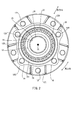
- FIG. 2 is a view of the hub unit shown in FIG. 1 as viewed from the inside of the vehicle toward the outside of the vehicle.
- FIG. 3 is an enlarged cross-sectional view of a magnetic encoder provided in the hub unit shown in FIG.
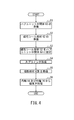
- FIG. 4 is a flowchart showing a manufacturing method of the hub unit shown in FIG.
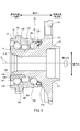
- FIG. 5 is a cross-sectional view of a hub unit intermediate body used for manufacturing the hub unit shown in FIG.
- FIG. 6 is a cross-sectional view of a magnetic seal member used for manufacturing the hub unit shown in FIG.
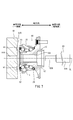
- FIG. 7 is a diagram for explaining a method of magnetizing the magnetic member shown in FIG.
- the manufacturing method of the hub unit according to the embodiment includes a process a), a process b), a process c), a process d), and a process e).
- a hub unit intermediate is prepared.
- the hub unit intermediate body includes an inner shaft, an inner ring fixed to an end portion in the axial direction of the inner shaft, and an outer ring disposed so as to be rotatable with respect to the inner shaft and the inner ring.
- a magnetic seal member is prepared.
- the magnetic seal member includes a seal member having an annular surface extending in a radial direction perpendicular to the axial direction when arranged coaxially with the central axis of the inner shaft, and an annular magnetic member disposed on the annular surface and having no magnetic pole formed thereon.
- a magnetic seal member is disposed in a gap formed between the inner ring and the outer ring in the hub unit intermediate body.
- the inner peripheral surface of the inner shaft of the hub unit intermediate body on which the magnetic seal member is disposed is cut to form a plurality of splines extending along the axial direction of the inner shaft on the inner peripheral surface of the inner shaft.
- a plurality of magnetic poles are formed in the circumferential direction of the magnetic member in the hub unit intermediate body on which a plurality of splines are formed (first configuration).
- a spline is formed on the inner peripheral surface of the inner shaft by cutting after arranging a magnetic member including a magnetic member on which no magnetic pole is formed between the inner ring and the outer ring. Thereafter, the magnetic member is magnetized. It is possible to prevent metal pieces generated by cutting of the inner peripheral surface of the inner shaft from adhering to the magnetic member due to magnetic force or scratching the magnetic member. Further, since the spline is formed on the hub unit intermediate body in which the inner shaft, the inner ring, and the outer ring are assembled, the spline can be prevented from being deformed. Therefore, it is possible to improve the measurement accuracy of the rotational speed of the wheel and improve the accuracy of the spline.
- the method for manufacturing the hub unit may further include a step f).
- step f) after step e), the magnetism remaining in the inner ring and the outer ring is removed (second configuration).
- the second configuration it is possible to prevent the magnetism remaining in the inner ring and the outer ring from affecting the detection accuracy of the rotational speed of the wheel. As a result, the measurement accuracy of the rotational speed of the wheel can be further improved.
- step e) in a state where the cylindrical magnetized yoke is disposed coaxially with the hub unit intermediate body, a plurality of the magnetized yokes positioned on the end surface of the magnetized yoke facing the hub unit intermediate body and arranged in the circumferential direction
- the iron core portion may be brought into contact with a magnetic member disposed in the hub unit intermediate body (third configuration).
- the plurality of magnetic poles formed on the magnetic member are in the circumferential direction. Arranged. Therefore, the measurement speed of the rotation speed of the wheel can be improved.
- FIG. 1 is a cross-sectional view of a hub unit 10 according to an embodiment of the present invention. That is, FIG. 1 is a cross-sectional view of the hub unit 10 in which the hub unit 10 is cut along a plane including the central axis CL.
- FIG. 2 is a view of the hub unit 10 shown in FIG. 1 as viewed from the inside of the vehicle to the outside of the vehicle.
- the axial direction of the hub unit 10 is a direction in which the central axis CL of the hub unit 10 extends.
- the radial direction of the hub unit 10 is a direction perpendicular to the central axis CL, that is, a direction perpendicular to the axial direction.
- the circumferential direction of the hub unit 10 is a circumferential direction around the central axis CL. In the state where the hub unit 10 is arranged in the vehicle, one axial end side (left end side in FIG. 1) of the hub unit 10 corresponds to the vehicle inner side, and the other axial end side (right end in FIG. 1) of the hub unit 10. Side) corresponds to the outside of the vehicle.
- the hub unit 10 includes an inner shaft 12, an inner ring 14, an outer ring 16, a plurality of rolling elements 18A, a plurality of rolling elements 18B, a cage 20A, a cage 20B, An encoder 22 and a seal member 24 are provided.
- the inner shaft 12 is an annular member having the central axis CL as an axis.
- the inner shaft 12 includes a main body 121.
- the main body 121 has a cylindrical shape and includes a hole 12A.
- the hole 12A passes through the main body 121 in the axial direction, and the central axis of the hole 12A coincides with the central axis line CL.
- the main body 121 includes a plurality of splines 26.
- the plurality of splines 26 are formed on the inner peripheral surface of the main body 121 (that is, the inner peripheral surface of the hole 12A).
- the plurality of splines 26 extend straight in the axial direction and are arranged at equal intervals in the circumferential direction. In other words, a plurality of grooves extending in the axial direction and formed at equal intervals in the circumferential direction are formed on the inner peripheral surface of the main body 121.
- the drive shaft is inserted into the hole 12A.
- Splines having the same pitch width as that of the plurality of splines 26 are formed on the outer peripheral side surface of the drive shaft.
- the main body 121 further includes a large diameter portion 12B, a medium diameter portion 12C, and a small diameter portion 12D.
- the large diameter portion 12B is located on the other end side in the axial direction from the medium diameter portion 12C and the small diameter portion 12D.
- the middle diameter portion 12C has a smaller outer diameter than the large diameter portion 12B.
- the medium diameter portion 12C is located between the large diameter portion 12B and the small diameter portion 12D in the axial direction.
- the middle diameter portion 12 ⁇ / b> C includes a raceway surface 32.
- the raceway surface 32 is formed on the outer peripheral surface of the medium diameter portion 12C.
- the small diameter portion 12D has a smaller outer diameter than the medium diameter portion 12C.
- the small diameter portion 12D is located next to the medium diameter portion 12C in the axial direction. That is, the small diameter portion 12D is located on one end side in the axial direction with respect to the medium diameter portion 12C and the large diameter portion 12B.
- the inner shaft 12 further includes a flange 12E.
- the flange 12 ⁇ / b> E is formed on the outer peripheral surface of the main body 121.
- the flange 12E is formed continuously in the circumferential direction. That is, the flange 12E is formed in an annular shape.
- the flange 12E has an outer diameter larger than that of the large diameter portion 12B.
- the flange 12E is positioned next to the large diameter portion 12B in the axial direction.
- flange 12E includes a plurality of holes 12F.
- the plurality of holes 12F are formed, for example, at equal intervals in the circumferential direction.
- a wheel (specifically, a wheel), a brake disk, or the like is attached to the inner shaft 12 by a bolt 34 inserted into each of the plurality of holes 12F.
- the inner ring 14 is arranged coaxially with the inner shaft 12. That is, the inner ring 14 is an annular member having the central axis CL as an axis. In other words, the axial direction of the inner ring 14 matches the axial direction of the inner shaft 12.
- the inner ring 14 includes a hole 14A.
- the hole 14A penetrates the inner ring 14 in the axial direction.
- the central axis of the hole 14A coincides with the central axis line CL.
- the inner ring 14 is fixed to the inner shaft 12. Specifically, the inner ring 14 is fixed to the outer peripheral portion of the inner shaft 12 by press-fitting the small diameter portion 12 ⁇ / b> D of the inner shaft 12 into the inner ring 14.
- the inner ring 14 includes a raceway surface 14B and a cylindrical surface 14C.
- the raceway surface 14 ⁇ / b> B is formed on the outer peripheral surface of the inner ring 14.
- 14C of cylindrical surfaces are formed in the outer peripheral surface of the inner ring
- the outer ring 16 is disposed on the radially outer side of the inner shaft 12 and the inner ring 14 and is positioned coaxially with the inner shaft 12 and the inner ring 14. That is, the outer ring 16 is an annular member having the central axis CL as an axis. The outer ring 16 is disposed so as to be rotatable with respect to the inner shaft 12 and the inner ring 14.
- the outer ring 16 includes a main body 161.
- the main body 161 has a cylindrical shape.
- the main body 161 includes a raceway surface 16A and a raceway surface 16B.
- the raceway surface 16 ⁇ / b> A and the raceway surface 16 ⁇ / b> B are formed on the inner peripheral surface of the main body 161.
- the track surface 16A and the track surface 16B are separated in the axial direction.
- the main body 161 further includes a cylindrical surface 54A and a cylindrical surface 54B.
- the cylindrical surface 54A and the cylindrical surface 54B are formed on the inner peripheral surface of the main body 161.
- the cylindrical surface 54A and the cylindrical surface 54B are separated in the axial direction.
- the cylindrical surface 54A is located at the end of the main body 161 on the other end side in the axial direction. In other words, the cylindrical surface 54A is positioned on the opposite side of the track surface 16B with respect to the track surface 16A in the axial direction.
- the cylindrical surface 54B is located at the end of the main body 161 on one end side in the axial direction. In other words, the cylindrical surface 54B is located on the opposite side of the track surface 16A with respect to the track surface 16B in the axial direction. That is, the track surface 16A and the track surface 16B are located between the cylindrical surface 54A and the cylindrical surface 54B in the axial direction.
- the outer ring 16 further includes a flange 56.
- the flange 56 is formed on the outer peripheral surface of the main body 161.
- the flange 56 is continuously formed in the circumferential direction. That is, the flange 56 is formed in an annular shape.
- the flange 56 includes a plurality of attachment portions 58.
- the plurality of attachment portions 58 are formed at predetermined positions in the circumferential direction, for example.
- Each of the plurality of attachment portions 58 includes a hole 58A.
- the suspension device is fixed to the outer ring 16 by bolts inserted into the holes 58A.
- the plurality of rolling elements 18 ⁇ / b> A are disposed between the inner shaft 12 and the outer ring 16.
- the plurality of rolling elements 18A are arranged at equal intervals in the circumferential direction by the cage 20A. Each of the plurality of rolling elements 18A comes into contact with the raceway surface 16A and the raceway surface 32.
- the plurality of rolling elements 18B are arranged between the inner ring 14 and the outer ring 16.
- the plurality of rolling elements 18B are arranged at equal intervals in the circumferential direction by the cage 20B.
- Each of the plurality of rolling elements 18B contacts the raceway surface 14B and the raceway surface 16B.
- the seal member 24 is disposed between the inner shaft 12 and the outer ring 16.
- the seal member 24 is an annular member and is press-fitted into the large-diameter portion 12B of the inner shaft 12.
- the seal member 24 is in contact with the outer peripheral side surface of the large-diameter portion 12B of the inner shaft 12 and the cylindrical surface 54A of the outer ring 16.
- the seal member 24 seals between the outer peripheral surface of the large-diameter portion 12B of the inner shaft 12 and the cylindrical surface 54A of the outer ring 16.
- the magnetic encoder 22 is disposed between the inner ring 14 and the outer ring 16. Specifically, the magnetic encoder 22 is disposed between the cylindrical surface 14C of the inner ring 14 and the cylindrical surface 54B of the outer ring 16.
- FIG. 3 is an enlarged cross-sectional view of the magnetic encoder 22 provided in the hub unit 10 shown in FIG.
- the magnetic encoder 22 includes a seal member 22A and a pulsar ring 22B.
- the seal member 22A is an annular member that extends continuously in the circumferential direction.
- the seal member 22 ⁇ / b> A includes a cored bar 42, a slinger 44, and a seal rubber 46.
- the slinger 44 is a member that extends continuously in the circumferential direction. That is, the sling 44 is an annular member centered on the central axis CL.
- the slinger 44 includes a cylindrical portion 44A and an annular plate portion 44B.
- the cylinder portion 44A extends in the axial direction.
- the annular plate portion 44B extends in the radial direction perpendicular to the axial direction.
- the annular plate portion 44B is formed with substantially the same width over the entire circumference in the circumferential direction. That is, the annular plate portion 44B has an annular shape when viewed from the axial direction.
- the annular plate portion 44B is connected to an end portion on one end side in the axial direction of the cylindrical portion 44A.
- the annular plate portion 44B extends outward in the radial direction from an end portion on one end side in the axial direction of the tubular portion 44A.
- the annular plate portion 44B includes an annular surface 44C.
- the annular surface 44C is a surface on one end side in the axial direction of the annular plate portion 44B.
- the annular surface 44 ⁇ / b> C corresponds to an end surface on one end side in the axial direction of the magnetic encoder 22.
- the metal core 42 is a member that extends continuously in the circumferential direction. That is, the cored bar 42 is an annular member having the central axis CL as an axis.
- the core metal 42 includes a cylindrical portion 42A and an annular plate portion 42B.
- the cylinder part 42A extends in the axial direction.
- the annular plate portion 42B extends in the radial direction perpendicular to the axial direction.
- the annular plate portion 42B is formed with substantially the same width over the entire circumference in the circumferential direction. That is, the annular plate portion 42B has an annular shape when viewed from the axial direction.
- the annular plate portion 42B is connected to the end on the other end side in the axial direction of the cylindrical portion 42A.
- the annular plate portion 42B extends radially inward from the end on the other end side in the axial direction of the cylindrical portion 42A.
- the seal rubber 46 is substantially the same as the surface of the cored bar 42 except for a part of the outer peripheral surface of the cylindrical part 42A and a part of the surface of the annular plate part 42B connected to the outer peripheral surface of the cylindrical part 42A. Cover the whole.
- the seal rubber 46 is bonded to the core metal 42, for example. That is, the seal rubber 46 is formed integrally with the core metal 42.
- the seal rubber 46 includes lips 46A, 46B, and 46C.
- Each of the lips 46A, 46B, 46C is formed over the entire circumference in the circumferential direction. That is, the lips 46A, 46B, 46C are annular members centered on the central axis CL.
- the lip 46 ⁇ / b> A extends from the base portion 461 of the seal rubber 46 located at the radially inner end of the annular plate portion 42 ⁇ / b> B of the core metal 42 toward the annular plate portion 44 ⁇ / b> B of the slinger 44.
- Each of the lips 46 ⁇ / b> B and 46 ⁇ / b> C extends from the base portion 461 toward the cylindrical portion 44 ⁇ / b> A of the slinger 44.
- the sealing member 22A is formed by combining the slinger 44 with the cored bar 42.
- the slinger 44 is arranged coaxially with the core metal 42. Specifically, the slinger 44 is disposed inside the cylindrical portion 42A.
- the cylindrical portion 44A of the slinger 44 faces the cylindrical portion 42A of the core metal 42 in the radial direction. As viewed from the radial direction, the entire slinger 44 is hidden by the cored bar 42.
- the annular plate portion 44B is opposed to the annular plate portion 42B in the axial direction. The slinger 44 is rotatable with respect to the core metal 42.
- the lips 46A, 46B, and 46C are in contact with the slinger 44. Specifically, the lip 46A is pressed against the annular plate portion 44B over the entire circumference in the circumferential direction by the elasticity of the lip 46A. The lip 46B is pressed against the cylindrical portion 44A over the entire circumference in the circumferential direction by the elasticity of the lip 46B. The lip 46C is pressed against the cylindrical portion 44A over the entire circumference in the circumferential direction by the elasticity of the lip 46C. As a result, the space between the metal core 42 and the slinger 44 is sealed by the seal rubber 46.
- the pulsar ring 22B is an annular member that is continuous in the circumferential direction. That is, the pulsar ring 22B is an annular member having the central axis CL as an axis. Referring to FIG. 2, pulsar ring 22B is a multipolar magnet in which N poles and S poles are alternately arranged in the circumferential direction.
- the pulsar ring 22B is fixed to an annular surface 44C that is an end surface on one end side in the axial direction of the annular plate portion 44B of the slinger 44.
- the pulsar ring 22B is fixed to the annular plate portion 44B by adhesion, for example.
- the pulsar ring 22B is formed of a material in which a magnetic powder and a binder are mixed.
- a magnetic powder for example, ferrite can be used.
- An organic polymer can be used as the binder.
- rubber materials such as acrylic rubber and nitrile rubber, thermoplastic resins, and the like can be used as the binder.
- a magnetic sensor is disposed opposite the pulsar ring 22B at a position inside the vehicle relative to the pulsar ring 22B.
- the pulsar ring 22 ⁇ / b> B rotates together with the inner shaft 12 and the inner ring 14.
- a magnetic sensor detects the change of the magnetism which arises with rotation of pulsar ring 22B as rotation of a wheel.
- FIG. 4 is a flowchart showing the manufacturing process of the hub unit 10. A method for manufacturing the hub unit 10 will be described with reference to FIG.
- FIG. 5 is a cross-sectional view of the hub unit intermediate body 60. That is, FIG. 5 is a cross-sectional view of the hub unit intermediate body 60 in which the hub unit intermediate body 60 is cut along a plane including the central axis CL.
- the difference between the hub unit intermediate 60 shown in FIG. 5 and the hub unit 10 shown in FIG. 1 is the following two points.
- the first difference is that the hub unit 10 includes the magnetic encoder 22, whereas the hub unit intermediate 60 does not include the magnetic encoder 22.
- the second difference is that the hub unit intermediate body 60 includes an inner shaft 61 instead of the inner shaft 12.
- the inner shaft 61 includes a main body 611.
- the main body 611 has a cylindrical shape and includes a hole 61A.
- the hole 61A passes through the main body 61 in the axial direction, and the central axis of the hole 61A coincides with the central axis CL.
- a plurality of splines 26 are formed on the inner peripheral surface of the inner shaft 12, whereas a plurality of splines 26 are not formed on the inner peripheral surface of the inner shaft 61. That is, the inner diameter of the hole 61A is smaller than the maximum diameter of the hole 12A of the inner shaft 12.
- the maximum diameter of the hole 12A is a value obtained by doubling the distance from the central axis CL to the bottom surface of the groove formed on the inner peripheral surface of the inner shaft 12.
- the configuration of the main body 611 is the same as that of the main body 121 except that it includes a hole 61A.
- the manufacturing method of the hub unit intermediate body 60 is not particularly limited.
- FIG. 6 is a partial cross-sectional view of the magnetic seal member 62 prepared in step S2.
- the magnetic seal member 62 shown in FIG. 6 is used for manufacturing the magnetic encoder 22 shown in FIG.
- the magnetic seal member 62 is not fixed to the hub unit intermediate body 60.
- FIG. 6 for convenience, when the magnetic seal member 62 is fixed to the hub unit intermediate body 60, one of the magnetic seal members 62 when the magnetic seal member 62 is cut along a plane including the central axis CL. The cross section of the part is shown. Further, FIG. 6 shows a direction when the magnetic seal member 62 is fixed to the hub unit intermediate body 60.
- the magnetic seal member 62 includes a seal member 22A and a magnetic member 62B.
- the magnetic seal member 62 includes a magnetic member 62B instead of the pulsar ring 22B.
- the other configuration of the magnetic seal member 62 is the same as that of the magnetic encoder 22.
- the magnetic member 62B has the same shape as the pulsar ring 22B and is an annular member that is continuous in the circumferential direction. That is, when the magnetic member 62B is fixed to the hub unit intermediate body 60, the magnetic member 62B is an annular member having the central axis CL as an axis. Similar to the pulsar ring 22B, the magnetic member 62B is formed of a material in which magnetic powder and a binder are mixed. The magnetic member 62B is not magnetized, and the N poles and S poles are not alternately arranged at equal intervals in the circumferential direction. That is, the magnetic member 62B is the pulsar ring 22B before being magnetized.
- the magnetic member 62B is fixed to an annular surface 44C, which is an end surface on one end side in the axial direction of the annular plate portion 44B of the slinger 44, similarly to the pulsar ring 22B.
- the annular surface 44 ⁇ / b> C corresponds to an end surface on one end side in the axial direction of the magnetic seal member 62.
- the magnetic seal member 62 is fixed to the hub unit intermediate 60 (step S3). Specifically, as shown in FIG. 3, the magnetic seal member 62 is press-fitted between the cylindrical surface 14 ⁇ / b> C of the inner ring 14 and the cylindrical surface 54 ⁇ / b> B of the outer ring 16, and between the inner ring 14 and the outer ring 16. A magnetic seal member 62 is disposed in the gap formed. More specifically, the cylindrical portion 42 ⁇ / b> A of the core metal 42 is press-fitted into the outer ring 16, and the inner ring 14 is press-fitted into the cylindrical portion 44 ⁇ / b> A of the slinger 44. As a result, the outer peripheral surface of the cylindrical portion 42A is in contact with the cylindrical surface 54B, and the inner peripheral surface of the cylindrical portion 44A is in contact with the cylindrical surface 14C of the inner ring 14.
- the seal member 24 is already disposed in the gap between the outer ring 16 and the large diameter portion 12 ⁇ / b> B of the inner shaft 12. As a result, the space between the outer ring 16 and the inner shaft 12 and the inner ring 14 is sealed by the seal member 24 and the magnetic seal member 62.
- a plurality of splines 26 are formed on the inner peripheral surface of main body 611 of inner shaft 61 (step S4).
- the inner peripheral surface of the main body 611 is cut, and a plurality of grooves extending in the axial direction are formed on the inner peripheral surface of the main body 611 at equal intervals in the circumferential direction.
- the inner shaft 61 of the hub unit intermediate body 60 becomes the inner shaft 12 including the plurality of splines 26.
- broaching can be used for cutting the inner peripheral surface of the main body 611.
- FIG. 7 is a diagram illustrating a method of magnetizing the magnetic member 62B. Referring to FIG. 7, a magnetizing yoke 81 is used for magnetizing magnetic member 62B.
- the magnetizing yoke 81 constitutes a magnetizing device together with a power supply device (not shown).
- the magnetized yoke 81 has a cylindrical shape and includes a hole 81A.
- the hole 81A penetrates the magnetized yoke 81 in the axial direction.
- the magnetized yoke 81 includes a plurality of iron core portions 82.
- the plurality of iron core portions 82 are the hub unit intermediate bodies among the axial end surfaces of the magnetizing yoke 81.
- 60 is disposed on the end surface 81B opposite to 60.
- the plurality of iron core portions 82 are arranged in the circumferential direction on the end surface 81B. That is, the plurality of iron core portions 82 are arranged in an annular region centering on the central axis in the end surface 81B.
- a coil is wound around each of the plurality of iron core portions 82.
- the power supply device controls the magnitude and direction of the current flowing through the coil wound around each of the plurality of iron core portions 82.
- the hub unit intermediate body 60 and the magnetized yoke 81 are aligned by centering using the centering member 83. And the magnetic member 62B is magnetized by making the iron core part 82 of the magnetizing yoke 81 contact the magnetic member 62B.
- the centering member 83 is inserted into the hole 12 ⁇ / b> A of the inner shaft 12 and the hole 81 ⁇ / b> A of the magnetizing yoke 81 from the other end side of the hub unit intermediate body 60.
- the centering member 83 is inserted such that the insertion portion 83A is located in the hole 12A of the inner shaft 12 and the insertion portion 83B is located in the hole 81A of the magnetizing yoke 81.
- the insertion portion 83A of the centering member 83 is not shown in FIG. 7, a spline is formed on the outer peripheral side surface in the same manner as the drive shaft. That is, the shape of the cross section perpendicular to the central axis CL in the insertion portion 83A is the same as the shape of the cross section perpendicular to the central axis CL of the hole 12A in the drive shaft. For this reason, the insertion portion 83 ⁇ / b> A is fitted into the inner shaft 12 by being inserted into the hole 12 ⁇ / b> A of the inner shaft 12.
- the insertion portion 83B of the centering member 83 has a cylindrical shape and is inserted into the hole 81A of the magnetizing yoke 81.
- the diameter of the insertion portion 83B is equal to the inner diameter of the hole 81A.
- the hub unit intermediate body 60 and the magnetizing yoke 81 are aligned by inserting the centering member 83 into the hole 12A of the inner shaft 12 and the hole 81A of the magnetizing yoke 81. That is, by using the centering member 83, the central axis of the magnetized yoke 81 can be made to coincide with the central axis CL of the hub unit intermediate body 60.
- the end surface 81B of the magnetizing yoke 81 is brought into contact with the end surface of the magnetic member 62B.
- the inner diameter of the annular region is the same as the inner diameter of the magnetic member 62B
- the outer diameter of the annular region is the outer diameter of the magnetic member 62B. Is the same. Therefore, when the magnetized yoke 81 aligned with the hub unit intermediate body 60 is brought into contact with the magnetic member 62B, the plurality of iron core portions 82 come into contact with the magnetic member 62B.
- a current is supplied from the power supply device to the coil wound around each of the plurality of iron core portions 82.
- the magnetic poles generated in the plurality of iron core portions 82 are transferred to the magnetic member 62B.
- the direction of the current flowing in the coil is adjusted so that different magnetic poles are generated in the two iron core portions 82 adjacent to each other in the circumferential direction. That is, the plurality of iron core portions where the magnetic poles are generated are in contact with the magnetic member 62B.
- the magnetic poles generated in the plurality of iron core portions 82 are transferred to the magnetic member 62B, whereby a plurality of magnetic poles as shown in FIG. 2 are arranged in the circumferential direction on the magnetic member 62B.
- the magnetic member 62B becomes the pulsar ring 22B by alternately arranging the N pole and the S pole at equal intervals in the circumferential direction of the magnetic member 62B.
- the magnetism in the inner ring 14 and the outer ring 16 is demagnetized (step S6).
- a method for demagnetizing the magnetism in the inner ring 14 and the outer ring 16 for example, an alternating current attenuation method or a thermal demagnetization method can be used.
- the alternating current attenuation method is a method in which a coil for passing an alternating current is brought close to the end faces on one end side of the inner ring 14 and the outer ring 16 to be demagnetized, and the current flowing in the coil is gradually weakened.
- the thermal demagnetization method is a method of removing magnetism by heating the end faces on one end side of the inner ring 14 and the outer ring 16 to be demagnetized to a Curie temperature.
- step S ⁇ b> 5 when the magnetized yoke 81 is brought into contact with the magnetic member 62 ⁇ / b> B in step S ⁇ b> 5, as shown in FIG. 7, the plurality of iron core portions 82 are on one end side in the axial direction of the inner ring 14 and the outer ring 16. It is located in the vicinity of the end face. As a result, not only the magnetic member 62B but also the end faces on one end side of the inner ring 14 and the outer ring 16 may be magnetized. When the inner ring 14 and the outer ring 16 are magnetized, the detection accuracy of the rotational speed of the wheel may be affected. In step S6, by demagnetizing the magnetism of the inner ring 14 and the outer ring 16, the detection accuracy of the rotational speed of the wheel can be improved.
- step S6 (refer to FIG. 4) may be omitted. Specifically, after the magnetic member 62B is magnetized in step S5, if the magnetism measured on the end faces on the one end side of the inner ring 14 and the outer ring 16 is less than or equal to a predetermined allowable value, step S6 is omitted. Also good.
- a predetermined allowable value for example, a lower limit value of magnetism that can be removed in the above demagnetization method can be used.
- the magnetic seal member 62 including the seal member 22A and the magnetic member 62B is provided on the hub unit intermediate body 60 including the inner shaft 61 in which the plurality of splines 26 are not formed. Fix it.
- a plurality of splines 26 are formed on the inner peripheral surface of the main body 611 by cutting the inner peripheral surface of the main body 611. Thereafter, the magnetic member 62B is magnetized.
- the magnetic member 62B of the magnetic seal member 62 is not magnetized. Metal pieces generated by cutting the inner peripheral surface of the main body 611 can be prevented from adhering to the magnetic member 62B due to magnetic force. Since the metal piece does not adhere to the magnetic member 62B due to the magnetic force, it is possible to prevent the metal member 62B from being damaged by the metal piece. As a result, the pulsar ring 22B can generate a magnetic field that is not affected by metal pieces or scratches, and thus can improve the detection accuracy of the rotational speed of the wheel.
- the plurality of splines 26 are formed by cutting the inner peripheral surface of the main body 611 of the hub unit intermediate body 60.
- the hub unit intermediate body 60 is configured by removing the magnetic encoder 22 from the hub unit 10. Since the plurality of splines 26 are formed after the small diameter portion 12D of the inner shaft 12 is press-fitted into the inner ring 14, it is possible to prevent the plurality of splines 26 from being deformed by assembling the hub unit intermediate body 60. Therefore, in the hub unit 10 manufactured by the manufacturing method described above, the molding accuracy of the plurality of splines 26 can be improved.
- the space between the outer ring 16 and the inner shaft 12 and the inner ring 14 has a seal member 24 and a magnetic seal member 62. It is sealed by. Accordingly, it is possible to prevent the metal generated when forming the plurality of splines 26 from entering between the space between the outer ring 16 and the inner shaft 12 and the inner ring 14, and the metal piece is formed into a plurality of rolling elements. It is possible to prevent the surfaces of 18A and the plurality of rolling elements 18B from being damaged.
- the magnetic member 62B is magnetized after the plurality of splines are formed on the inner peripheral surface of the main body 611. Thereby, the detection precision of the rotation speed of a wheel can be improved. This will be described in detail below.
- the magnetic encoder 22 including the pulsar ring 22B is press-fitted between the cylindrical surface 14C of the inner ring 14 and the cylindrical surface 54B of the outer ring 16, the magnetic encoder 22 may be deformed.
- the magnetic encoder 22 may be deformed into an oval shape by press-fitting.
- the plurality of magnetic poles in the pulsar ring 22B are arranged in an elliptical shape when viewed from one end side in the axial direction. With the deformation of the pulsar ring 22B, the arrangement of the plurality of magnetic poles in the pulsar ring 22B also changes, so that the measurement speed of the rotational speed of the wheel is reduced.
- the magnetic member 62B is magnetized after the plurality of splines are formed on the inner peripheral surface of the main body 611.
- the plurality of iron core portions 82 in the magnetized yoke 81 are arranged in the circumferential direction. Therefore, even if the magnetic member 62B is slightly deformed by press fitting, the magnetic poles are arranged in the circumferential direction in the magnetic member 62B in accordance with the arrangement of the plurality of iron core portions 82.
Landscapes
- Engineering & Computer Science (AREA)
- General Engineering & Computer Science (AREA)
- Mechanical Engineering (AREA)
- Rolling Contact Bearings (AREA)
- Mounting Of Bearings Or Others (AREA)
- Sealing Of Bearings (AREA)
Abstract
車輪の回転数の検出精度と、内軸の内周面に形成されるスプラインの成形精度との両者を向上させることができる駆動輪用のハブユニットの製造方法を提供する。内軸(61)と、内軸(61)の一方側の端部に固定された内輪(14)と、内軸(61)及び内輪(14)に対して回転可能に配置された外輪(16)とを備えるハブユニット中間体(60)を準備する(ステップS1)。シール部材(22A)と、磁極が形成されていない環状の磁性部材(62B)とを備える磁性シール部材(62)を準備する(ステップS2)。内輪(14)と外輪(16)との間に磁性シール部材(62)を固定する(ステップS3)。内軸(61)の内周面を切削して、軸方向に沿って伸びるスプライン(26)を内軸(61)の内周面に形成する(ステップS4)。複数のスプライン(26)が形成されたハブユニット中間体(60)において、磁性部材(62B)の周方向に複数の磁極を形成する(ステップS5)。
Description
本発明の一態様は、車両の駆動輪用のハブユニットの製造方法に関する。
自動車の車輪を懸架装置に対して回転可能に取り付けるために、ハブユニットが用いられている。また、アンチロックブレーキシステム(ABS)を備える自動車では、車輪の回転数を検出するための磁気エンコーダが、ハブユニットに取り付けられている。磁気エンコーダは、環状であり、複数の磁極を有する。複数の磁極は、磁気エンコーダの周方向にN極とS極が交互に位置するように配列されている。
日本国特開2007-254097号公報には、磁気エンコーダを有する軸受装置の製造方法が開示されている。この製造方法により製造される軸受装置は、軸受部と、磁気エンコーダとしての回転センサ部とを有する。軸受部は、内輪と、内輪に対して回転可能に配置された外輪と、内輪と外輪との間に配置された複数の転動体とを有する。回転センサ部は、ベース部材と、磁気パルサ部とを有する。
日本国特開2007-254097号公報に開示されている製造方法では、最初に、軸受部が組み立てられる。ベース部材は、環状であり、組み立てられた軸受部における内輪の外周側面に圧入される。インクジェット方式でベース部材の外周側面に磁性インクを吐出することにより、ベース部材の外周側面に樹脂層が形成される。樹脂層が、着磁装置により着磁されることにより、磁気パルサ部が形成される。
また、ハブユニットには、駆動輪用のハブユニットと、従動輪用のハブユニットとの2種類が存在する。
駆動輪用のハブユニットは、内軸と、内輪と、外輪と、複数の第1転動体と、複数の第2転動体と、シール部材と、パルサリングとを含む。
内輪は、内軸と同軸に配置され、内軸の軸方向における一方側の端部に固定される。外輪は、内軸及び内輪に対して回転可能に配置される。第1転動体は、内軸と外輪との間に配置される。第2転動体は、内輪と外輪との間に配置される。シール部材は、環状であり、内輪と外輪との間に形成される隙間を封止する。また、シール部材の軸方向の一方側の端面には、周方向に複数の磁極が配列されたパルサリングが配置されている。
内軸を軸方向に貫通する孔の内周面には、軸方向に伸びる複数のスプラインが予め形成されている。駆動輪用のハブユニットを製造する際に、内軸の一方側の端部が内輪に圧入される。圧入により、内軸の内周面に予め形成されたスプラインが微少に変形する。
内軸の内周面に形成されたスプラインが微少ではあるが変形することによって、内軸の孔に挿入された駆動軸が回転する際に、内軸の内周面に形成されたスプラインと、駆動軸の外周側面に形成されたスプラインとの接触部で、金属音が発生する場合がある。金属音の発生を防ぐためには、内軸の内周面に形成されたスプラインの変形を防ぎ、内軸の内周面に形成されたスプラインの成形精度を向上させることが望ましい。
駆動輪用のハブユニットを組み立てた後に、内軸の内周面を切削してスプラインを形成することにより、内軸の内周面に形成されたスプラインの変形を防ぐことが可能である。しかし、切削により発生する金属片が、パルサリングの磁極に付着する虞がある。金属片がパルサリングにおける磁極に付着した場合、車輪の回転数の検出精度が低下する。また、金属片によりパルサリングの表面に傷が付いた場合、車輪の回転数の検出精度が低下する。
本発明の一態様の目的は、車輪の回転数の検出精度と、内軸の内周面に形成されるスプラインの成形精度との両者を向上させることができる駆動輪用のハブユニットの製造方法を提供することである。
本開示に係るハブユニットの製造方法は、工程a)と、工程b)と、工程c)と、工程d)と、工程e)とを備える。工程a)では、ハブユニット中間体を準備する。ハブユニット中間体は、内軸と、内軸の軸方向の端部に固定された内輪と、内軸及び内輪に対して回転可能に配置された外輪とを備える。工程b)では、磁性シール部材を準備する。磁性シール部材は、内軸の中心軸と同軸に配置した場合に軸方向に垂直な径方向に広がる環状面を有するシール部材と、環状面に配置されるとともに磁極が形成されていない環状の磁性部材とを備える。工程c)では、ハブユニット中間体における内輪と外輪との間に形成される隙間に、磁性シール部材を配置する。工程d)では、磁性シール部材が配置されたハブユニット中間体における内軸の内周面を切削して、内軸の軸方向に沿って伸びる複数のスプラインを内軸の内周面に形成する。工程e)では、複数のスプラインが形成されたハブユニット中間体において、磁性部材の周方向に複数の磁極を形成する。
本開示に係るハブユニットの製造方法によれば、車輪の回転数の計測精度を向上させ、かつ、スプラインの精度を向上させることができる。
実施形態に係るハブユニットの製造方法は、工程a)と、工程b)と、工程c)と、工程d)と、工程e)とを備える。工程a)では、ハブユニット中間体を準備する。ハブユニット中間体は、内軸と、内軸の軸方向の端部に固定された内輪と、内軸及び内輪に対して回転可能に配置された外輪とを備える。工程b)では、磁性シール部材を準備する。磁性シール部材は、内軸の中心軸と同軸に配置した場合に軸方向に垂直な径方向に広がる環状面を有するシール部材と、環状面に配置されるとともに磁極が形成されていない環状の磁性部材とを備える。工程c)では、ハブユニット中間体における内輪と外輪との間に形成される隙間に、磁性シール部材を配置する。工程d)では、磁性シール部材が配置されたハブユニット中間体における内軸の内周面を切削して、内軸の軸方向に沿って伸びる複数のスプラインを内軸の内周面に形成する。工程e)では、複数のスプラインが形成されたハブユニット中間体において、磁性部材の周方向に複数の磁極を形成する(第1の構成)。
第1の構成によれば、磁極が形成されていない磁性部材を備える磁性部材を内輪と外輪との間に配置した後に、内軸の内周面にスプラインが切削により形成される。その後、磁性部材が着磁される。内軸の内周面の切削により発生する金属片が、磁力により磁性部材に付着したり、磁性部材に傷を付けたりすることを防ぐことができる。また、スプラインの形成が、内軸と内輪と外輪とが組み付けられたハブユニット中間体に対して行われるため、スプラインの変形を防ぐことができる。従って、車輪の回転数の計測精度を向上させ、かつ、スプラインの精度を向上させることができる。
ハブユニットの製造方法は、さらに、工程f)を備えてもよい。工程f)は、工程e)の後に、内輪及び外輪に残留している磁気を除去する(第2の構成)。
第2の構成によれば、内輪及び外輪に残留している磁気が車輪の回転数の検出精度に影響を及ぼすことを防ぐことができる。その結果、車輪の回転数の計測精度をさらに向上させることができる。
上記工程e)において、円柱形状の着磁ヨークをハブユニット中間体と同軸に配置した状態で、ハブユニット中間体に対向する着磁ヨークの端面に位置し、かつ、周方向に配列された複数の鉄芯部をハブユニット中間体に配置された磁性部材に接触させてもよい(第3の構成)。
第3の構成によれば、内輪と外輪との間に形成される隙間に配置された磁性シール部材が微少に変形した場合であっても、磁性部材に形成される複数の磁極は、周方向に配列される。従って、車輪の回転数の計測速度を向上させることができる。
以下、図面を参照し、本発明の実施の形態を詳しく説明する。図中同一又は相当部分には同一符号を付してその説明は繰り返さない。
図1は、本発明の実施の形態に係るハブユニット10の断面図である。つまり、図1は、中心軸線CLを含む面でハブユニット10を切断したハブユニット10の断面図である。図2は、図1に示すハブユニット10を車両内側から車両外側の方向に見た図である。
なお、以下の説明において、ハブユニット10の軸方向は、ハブユニット10の中心軸線CLが延びる方向である。ハブユニット10の径方向は、中心軸線CLに垂直な方向、つまり、軸方向に垂直な方向である。ハブユニット10の周方向は、中心軸線CL周りの円周方向である。ハブユニット10が車両に配置された状態では、ハブユニット10の軸方向一端側(図1中の左端側)が車両内側に相当し、ハブユニット10の軸方向他端側(図1中の右端側)が車両外側に相当する。
(1.ハブユニット10の構成)
図1を参照して、ハブユニット10は、内軸12と、内輪14と、外輪16と、複数の転動体18Aと、複数の転動体18Bと、保持器20Aと、保持器20Bと、磁気エンコーダ22と、シール部材24とを備える。
図1を参照して、ハブユニット10は、内軸12と、内輪14と、外輪16と、複数の転動体18Aと、複数の転動体18Bと、保持器20Aと、保持器20Bと、磁気エンコーダ22と、シール部材24とを備える。
内軸12は、中心軸線CLを軸心とする環状の部材である。内軸12は、本体121を含む。本体121は、筒形状であり、孔12Aを含む。孔12Aは、本体121を軸方向に貫通しており、孔12Aの中心軸は、中心軸線CLに一致する。
本体121は、複数のスプライン26を含む。複数のスプライン26は、本体121の内周面(つまり孔12Aの内周面)に形成されている。複数のスプライン26は、軸方向にまっすぐ延びており、周方向に等間隔に配置されている。言い換えれば、本体121の内周面には、周方向に等間隔に形成された軸方向に延びる複数の溝が形成されている。
駆動軸が孔12Aに挿入される。駆動軸の外周側面には、複数のスプライン26のピッチ幅と同じピッチ幅のスプラインが形成されている。駆動軸が孔12Aに挿入されることにより、内軸12は、駆動軸と嵌め合わされ、駆動軸の回転に応じて回転する。
本体121は、さらに、大径部12B、中径部12C及び小径部12Dを含む。大径部12Bは、中径部12C及び小径部12Dよりも軸方向他端側に位置する。
中径部12Cは、大径部12Bよりも小さな外径を有する。中径部12Cは、軸方向で大径部12Bと小径部12Dとの間に位置する。中径部12Cは、軌道面32を含む。軌道面32は、中径部12Cの外周面に形成されている。
小径部12Dは、中径部12Cよりも小さな外径を有する。小径部12Dは、軸方向で中径部12Cの隣に位置する。つまり、小径部12Dは、中径部12C及び大径部12Bよりも軸方向一端側に位置する。
内軸12は、さらに、フランジ12Eを含む。フランジ12Eは、本体121の外周面に形成されている。フランジ12Eは、周方向に連続して形成されている。つまり、フランジ12Eは、環状に形成されている。フランジ12Eは、大径部12Bよりも大きな外径を有する。フランジ12Eは、軸方向で大径部12Bの隣に位置する。
図2を参照して、フランジ12Eは、複数の孔12Fを含む。複数の孔12Fは、例えば、周方向に等間隔に形成されている。複数の孔12Fの各々に挿入されるボルト34により、内軸12に車輪(具体的には、ホイール)やブレーキディスク等が取り付けられる。
再び、図1を参照して、内輪14は、内軸12と同軸上に配置される。つまり、内輪14は、中心軸線CLを軸心とする環状の部材である。別の表現をすれば、内輪14の軸方向は、内軸12の軸方向と一致している。
内輪14は、孔14Aを含む。孔14Aは、内輪14を軸方向に貫通している。孔14Aの中心軸は、中心軸線CLに一致する。内輪14は、内軸12に固定される。具体的には、内軸12の小径部12Dが内輪14に圧入されることにより、内輪14が内軸12の外周部分に固定される。
内輪14は、軌道面14Bと筒状面14Cとを含む。軌道面14Bは、内輪14の外周面に形成されている。筒状面14Cは、内輪14の外周面に形成されており、軌道面14Bよりも軸方向一端側に位置する。
外輪16は、内軸12及び内輪14の径方向外側に配置され、内軸12及び内輪14と同軸上に位置している。つまり、外輪16は、中心軸線CLを軸心とする環状の部材である。外輪16は、内軸12及び内輪14に対して回転可能に配置されている。外輪16は、本体161を含む。本体161は、筒形状を有する。
本体161は、軌道面16Aと、軌道面16Bとを含む。軌道面16A及び軌道面16Bは、本体161の内周面に形成されている。軌道面16A及び軌道面16Bは、軸方向で離れている。
本体161は、さらに、筒状面54Aと、筒状面54Bとを含む。筒状面54A及び筒状面54Bは、本体161の内周面に形成されている。筒状面54A及び筒状面54Bは、軸方向で離れている。
筒状面54Aは、本体161における軸方向他端側の端部に位置する。言い換えれば、筒状面54Aは、軸方向で、軌道面16Aに対して、軌道面16Bとは反対側に位置する。筒状面54Bは、本体161における軸方向一端側の端部に位置する。言い換えれば、筒状面54Bは、軸方向で、軌道面16Bに対して、軌道面16Aとは反対側に位置する。つまり、軸方向で筒状面54Aと筒状面54Bとの間に、軌道面16A及び軌道面16Bが位置する。
外輪16は、さらに、フランジ56を含む。フランジ56は、本体161の外周面に形成されている。
図2を参照して、フランジ56は、周方向に連続して形成されている。つまり、フランジ56は、環状に形成されている。フランジ56は、複数の取付部58を含む。複数の取付部58は、例えば、周方向における所定の位置に形成されている。複数の取付部58の各々は、孔58Aを含む。孔58Aに挿入されるボルトにより、外輪16に懸架装置が固定される。
複数の転動体18Aは、内軸12と外輪16との間に配置される。複数の転動体18Aは、保持器20Aにより、周方向に等間隔に配置される。複数の転動体18Aの各々は、軌道面16Aと軌道面32とに接触する。
複数の転動体18Bは、内輪14と外輪16との間に配置される。複数の転動体18Bは、保持器20Bにより、周方向に等間隔に配置される。複数の転動体18Bの各々は、軌道面14Bと軌道面16Bとに接触する。
シール部材24は、内軸12と外輪16との間に配置される。シール部材24は、環状部材であり、内軸12の大径部12Bに圧入される。シール部材24は、内軸12の大径部12Bの外周側面と、外輪16の筒状面54Aとに接触している。この結果、内軸12の大径部12Bの外周面と、外輪16の筒状面54Aとの間が、シール部材24によりシールされる。
磁気エンコーダ22は、内輪14と外輪16との間に配置される。具体的には、磁気エンコーダ22は、内輪14の筒状面14Cと外輪16の筒状面54Bとの間に配置される。
図3は、図1に示すハブユニット10が備える磁気エンコーダ22の拡大断面図である。図3を参照して、磁気エンコーダ22は、シール部材22Aと、パルサリング22Bとを備える。
シール部材22Aは、周方向に連続して延びる環状の部材である。シール部材22Aは、芯金42と、スリンガ44と、シールゴム46とを含む。
スリンガ44は、周方向に連続して延びる部材である。つまり、スリング44は、中心軸線CLを中心とする環状の部材である。スリンガ44は、筒部44Aと、環状板部44Bとを含む。
筒部44Aは、軸方向に延びる。環状板部44Bは、軸方向に垂直な径方向に広がる。環状板部44Bは、周方向で全周に亘って略同じ幅で形成されている。つまり、環状板部44Bは、軸方向から見て、円環形状を有する。環状板部44Bは、筒部44Aにおける軸方向の一端側の端部に接続されている。環状板部44Bは、筒部44Aにおける軸方向一端側の端部から径方向で外側に延びている。環状板部44Bは、環状面44Cを含む。環状面44Cは、環状板部44Bの軸方向一端側の面である。環状面44Cは、磁気エンコーダ22の軸方向一端側の端面に相当する。
芯金42は、周方向に連続して延びる部材である。つまり、芯金42は、中心軸線CLを軸心とする環状の部材である。芯金42は、筒部42Aと、環状板部42Bとを含む。
筒部42Aは、軸方向に伸びる。環状板部42Bは、軸方向に垂直な径方向に広がる。環状板部42Bは、周方向で全周にわたって略同じ幅で形成されている。つまり、環状板部42Bは、軸方向から見て、円環形状を有する。環状板部42Bは、筒部42Aにおける軸方向の他端側の端に接続されている。環状板部42Bは、筒部42Aにおける軸方向の他端側の端から径方向で内側に延びている。
シールゴム46は、筒部42Aの外周面の一部と、環状板部42Bの表面のうち、筒部42Aの外周面と接続される表面の一部とを除いて、芯金42の表面の略全体を覆う。シールゴム46は、例えば、芯金42に接着されている。つまり、シールゴム46は、芯金42と一体的に形成されている。
シールゴム46は、リップ46A、46B、46Cを含む。リップ46A、46B、46Cの各々は、周方向で全周に亘って形成されている。つまり、リップ46A、46B、46Cは、中心軸線CLを中心とする環状の部材である。リップ46Aは、芯金42の環状板部42Bの径方向の内側端部に位置するシールゴム46の基部461から、スリンガ44の環状板部44Bに向かって延びる。リップ46B及び46Cの各々は、基部461からスリンガ44の筒部44Aに向かって延びる。
スリンガ44が芯金42と組み合わせられることで、シール部材22Aが形成される。シール部材22Aにおいて、スリンガ44は、芯金42と同軸上に配置される。具体的には、スリンガ44は、筒部42Aの内側に配置される。スリンガ44の筒部44Aは、芯金42の筒部42Aに対して、径方向で対向する。径方向から見て、スリンガ44の全体が芯金42で隠れる。環状板部44Bは、環状板部42Bに対して、軸方向で対向する。スリンガ44は、芯金42に対して回転可能である。
シール部材22Aにおいて、リップ46A、46B、46Cは、スリンガ44に接している。具体的には、リップ46Aは、リップ46Aが有する弾性により、周方向で全周に亘って、環状板部44Bに押し付けられている。リップ46Bは、リップ46Bが有する弾性により、周方向で全周に亘って、筒部44Aに押し付けられている。リップ46Cは、リップ46Cが有する弾性により、周方向で全周に亘って、筒部44Aに押し付けられている。その結果、芯金42とスリンガ44との間が、シールゴム46により、シールされる。
パルサリング22Bは、周方向に連続した環状の部材である。つまり、パルサリング22Bは、中心軸線CLを軸心とする環状の部材である。図2を参照して、パルサリング22Bは、周方向に交互にN極とS極とが配列された多極磁石である。
図3を参照して、パルサリング22Bは、スリンガ44の環状板部44Bにおける軸方向の一端側の端面である環状面44Cに固定されている。パルサリング22Bは、例えば、接着により環状板部44Bに固定される。
パルサリング22Bは、磁性体の粉末と、バインダとが混合された材料から形成されている。磁性体の粉末としては、例えば、フェライト等を用いることができる。バインダとしては、有機高分子を用いることができる。例えば、アクリルゴム、ニトリルゴム等のゴム材料や、熱可塑性樹脂などをバインダとして用いることができる。
外輪16が懸架装置に固定された状態において、パルサリング22Bよりも車両内側の位置には、磁気センサがパルサリング22Bに対向して配置される。パルサリング22Bは、内軸12及び内輪14とともに回転する。磁気センサは、パルサリング22Bの回転に伴って生じる磁気の変化を、車輪の回転として検出する。
(2.ハブユニット10の製造方法)
図4は、ハブユニット10の製造工程を示すフローチャートである。図4を参照しながら、ハブユニット10の製造方法を説明する。
図4は、ハブユニット10の製造工程を示すフローチャートである。図4を参照しながら、ハブユニット10の製造方法を説明する。
最初に、ハブユニット中間体を準備する(ステップS1)。図5は、ハブユニット中間体60の断面図である。つまり、図5は、中心軸線CLを含む面でハブユニット中間体60を切断したハブユニット中間体60の断面図である。
図5に示すハブユニット中間体60と図1に示すハブユニット10との相違点は、以下の2点である。
第1の相違点は、ハブユニット10が磁気エンコーダ22を備えているのに対して、ハブユニット中間体60が磁気エンコーダ22を備えていないことである。第2の相違点は、ハブユニット中間体60が、内軸12に代えて、内軸61を備えていることである。
内軸61は、本体611を含む。本体611は、筒形状であり、孔61Aを含む。孔61Aは、本体61を軸方向に貫通しており、孔61Aの中心軸は、中心軸線CLに一致する。内軸12の内周面には、複数のスプライン26が形成されているのに対して、内軸61の内周面には、複数のスプライン26が形成されていない。つまり、孔61Aの内径は、内軸12の孔12Aの最大径よりも小さい。孔12Aの最大径は、中心軸線CLから、内軸12の内周面に形成されている溝の底面までの距離を2倍した数値である。本体611の構成は、孔61Aを含む点を除き、本体121と同じである。
ステップS1において、図5に示すハブユニット中間体60を準備することができれば、ハブユニット中間体60の製造方法は特に限定されない。
図4を参照して、ステップS1の後に、磁性シール部材を準備する(ステップS2)。図6は、ステップS2で準備される磁性シール部材62の部分断面図である。図6に示す磁性シール部材62は、図3に示す磁気エンコーダ22の製造に用いられる。
ステップS2を実行する時点では、磁性シール部材62は、ハブユニット中間体60に固定されていない。しかし、図6では、便宜的に、磁性シール部材62がハブユニット中間体60に固定された場合において、磁性シール部材62を中心軸線CLを含む面で切断した場合における、磁性シール部材62の一部の断面を示している。また、図6において、磁性シール部材62がハブユニット中間体60に固定された場合における方向を示している。
図6を参照して、磁性シール部材62は、シール部材22Aと、磁性部材62Bとを含む。磁性シール部材62は、パルサリング22Bに代えて磁性部材62Bを備えている。磁性シール部材62のその他の構成については、磁気エンコーダ22の構成と同じである。
磁性部材62Bは、パルサリング22Bと同一の形状であり、周方向に連続した環状の部材である。つまり、磁性部材62Bは、ハブユニット中間体60に固定された場合、中心軸線CLを軸心とする環状の部材である。磁性部材62Bは、パルサリング22Bと同様に、磁性体の粉末と、バインダとが混合された材料から形成されている。磁性部材62Bは着磁されておらず、N極とS極とが周方向に等間隔に交互に配列されていない。つまり、磁性部材62Bは、着磁される前のパルサリング22Bである。
磁性部材62Bは、パルサリング22Bと同様に、スリンガ44の環状板部44Bにおける軸方向の一端側の端面である環状面44Cに固定されている。環状面44Cは、磁性シール部材62の軸方向一端側の端面に相当する。
再び、図4を参照して、ステップS2の後に、磁性シール部材62をハブユニット中間体60に固定する(ステップS3)。具体的には、図3に示すように、磁性シール部材62を、内輪14の筒状面14Cと外輪16の筒状面54Bとの間に圧入して、内輪14と外輪16との間に形成される隙間に磁性シール部材62を配置する。さらに具体的には、芯金42の筒部42Aが外輪16に圧入され、内輪14が、スリンガ44の筒部44Aに圧入される。この結果、筒部42Aの外周面が筒状面54Bに接触し、かつ、筒部44Aの内周面が内輪14の筒状面14Cに接触する。
ハブユニット中間体60において、シール部材24が、外輪16と内軸12の大径部12Bとの間の隙間に既に配置されている。この結果、外輪16と内軸12及び内輪14との間の空間が、シール部材24及び磁性シール部材62によりシールされる。
図4を参照して、磁性シール部材62が固定されたハブユニット中間体60において、軸方向に延びる複数のスプライン26を、内軸61の本体611の内周面に形成する(ステップS4)。具体的には、本体611の内周面を切削して、軸方向に延びる複数の溝を、周方向で等間隔に本体611の内周面に形成する。ステップS4が実行されることにより、ハブユニット中間体60の内軸61は、複数のスプライン26を含む内軸12となる。本体611の内周面の切削には、例えば、ブローチ加工を用いることができる。
図4を参照して、磁性シール部材62が固定されたハブユニット中間体60において、軸方向に延びる複数のスプライン26を、内軸61の本体611の内周面に形成する(ステップS4)。具体的には、本体611の内周面を切削して、軸方向に延びる複数の溝を、周方向で等間隔に本体611の内周面に形成する。ステップS4が実行されることにより、ハブユニット中間体60の内軸61は、複数のスプライン26を含む内軸12となる。本体611の内周面の切削には、例えば、ブローチ加工を用いることができる。
次に、磁性シール部材62の磁性部材62Bを着磁する(ステップS5)。図7は、磁性部材62Bを着磁する方法を説明する図である。図7を参照して、磁性部材62Bの着磁には、着磁ヨーク81が用いられる。
着磁ヨーク81は、図示しない電源装置とともに、着磁装置を構成する。着磁ヨーク81は、円柱形状であり、孔81Aを含む。孔81Aは、着磁ヨーク81を軸方向に貫通している。
さらに、着磁ヨーク81は、複数の鉄芯部82を含む。ハブユニット中間体60と着磁ヨーク81とが、図7に示す位置関係で配置されている場合、複数の鉄芯部82は、着磁ヨーク81の軸方向の端面のうち、ハブユニット中間体60に対向する端面81Bに配置されている。複数の鉄芯部82は、端面81Bにおいて周方向に配列されている。つまり、複数の鉄芯部82は、端面81Bにおいて中心軸を中心にした円環状領域に配置されている。
図7に示していないが、着磁ヨーク81において、複数の鉄芯部82の各々の周囲には、コイルが巻かれている。電源装置は、複数の鉄芯部82の各々に巻かれているコイルに流れる電流の大きさ及び向きを制御する。
芯出部材83を用いた芯出しにより、ハブユニット中間体60と着磁ヨーク81との位置合わせを行う。そして、着磁ヨーク81の鉄芯部82を磁性部材62Bに接触させることにより、磁性部材62Bを着磁する。
具体的には、芯出部材83を、ハブユニット中間体60の他端側から、内軸12の孔12Aと、着磁ヨーク81の孔81Aに挿入する。芯出部材83は、挿入部83Aが内軸12の孔12A内に位置し、挿入部83Bが着磁ヨーク81の孔81A内に位置するように挿入される。
芯出部材83の挿入部83Aは、図7に示していないが、駆動軸と同様に、外周側面にスプラインが形成されている。つまり、挿入部83Aにおける中心軸線CLに垂直な断面の形状は、駆動軸における孔12Aの中心軸線CLに垂直な断面の形状と同じである。このため、挿入部83Aは、内軸12の孔12Aに挿入されることにより、内軸12と嵌め合わされる。
芯出部材83の挿入部83Bは、円筒形状であり、着磁ヨーク81の孔81Aに挿入される。挿入部83Bの径は、孔81Aの内径と等しい。
このように、芯出部材83を内軸12の孔12A及び着磁ヨーク81の孔81Aに挿入することで、ハブユニット中間体60と着磁ヨーク81とが位置合わせされる。つまり、芯出部材83を用いることにより、着磁ヨーク81の中心軸を、ハブユニット中間体60の中心軸線CLに一致させることができる。
芯出部材83を、着磁ヨーク81とハブユニット中間体60の内軸12とに挿入した状態で、着磁ヨーク81の端面81Bを磁性部材62Bの端面に接触させる。複数の鉄芯部82が配置されている端面81Bの円環状領域において、円環状領域の内径は、磁性部材62Bの内径と同じであり、円環状領域の外径は、磁性部材62Bの外径と同じである。従って、ハブユニット中間体60に位置合わせされた着磁ヨーク81を、磁性部材62Bに接触された場合、複数の鉄芯部82が、磁性部材62Bに接触する。
複数の鉄芯部82が磁性部材62Bに接触した状態で、電源装置から複数の鉄芯部82の各々に巻かれたコイルに電流を供給する。電流がコイルに流れることにより、磁極が、複数の鉄芯部82に発生する。複数の鉄芯部82に発生した磁極が、磁性部材62Bに転写される。コイルに流れる電流の向きは、周方向に互いに隣接する2つの鉄芯部82で互いに異なる磁極が発生するように調整される。つまり、各々において磁極が発生した複数の鉄芯部が、磁性部材62Bに接触する。複数の鉄芯部82に発生した磁極が磁性部材62Bに転写されることにより、磁性部材62Bには、図2に示すような複数の磁極が周方向に配列される。
このように、磁性部材62Bの周方向に等間隔にN極とS極とを交互に配列することにより、磁性部材62Bがパルサリング22Bとなる。
次に、図4を参照して、内輪14及び外輪16における磁気を脱磁する(ステップS6)。内輪14及び外輪16における磁気を脱磁する方法として、例えば、交流電流減衰法や、熱脱磁法を用いることができる。交流電流減衰法は、脱磁の対象である内輪14及び外輪16の一端側の端面に交流電流を流すコイルを近づけ、コイルに流れる電流を徐々に弱めていく方法である。熱脱磁法は、脱磁の対象である内輪14及び外輪16の一端側の端面をキュリー温度まで加熱することにより、磁気を取り除く方法である。
図4に示すように、ステップS5において、着磁ヨーク81を磁性部材62Bに接触させた場合、複数の鉄芯部82は、図7に示すように、内輪14及び外輪16の軸方向一端側の端面の近傍に位置している。その結果、磁性部材62Bだけでなく、内輪14及び外輪16の各々の一端側の端面が着磁される場合がある。内輪14及び外輪16が着磁された場合、車輪の回転数の検出精度に影響を及ぼす虞がある。ステップS6において、内輪14及び外輪16の磁気を脱磁することにより、車輪の回転数の検出精度を向上させることができる。
なお、ハブユニット10を製造するにあたり、ステップS6(図4参照)を省略してもよい。具体的には、ステップS5において磁性部材62Bが着磁された後に、内輪14及び外輪16の一端側の端面で計測された磁気が、所定の許容値以下である場合、ステップS6を省略してもよい。所定の許容値として、例えば、上記の脱磁法において除去することができる磁気の下限値を用いることができる。
本実施の形態に係るハブユニット10の製造方法では、複数のスプライン26が形成されていない内軸61を含むハブユニット中間体60に、シール部材22Aと磁性部材62Bとを含む磁性シール部材62を固定する。磁性シール部材62が固定されたハブユニット中間体60において、本体611の内周面を切削することにより、本体611の内周面に複数のスプライン26を形成する。その後、磁性部材62Bが着磁される。
つまり、本体611の内周面を切削する際において、磁性シール部材62の磁性部材62Bは、着磁されていない。本体611の内周面の切削により発生する金属片は、磁力により磁性部材62Bに付着することを防ぐことができる。金属片が磁力により磁性部材62Bに付着しないため、金属片により磁性部材62Bに傷が発生することを防ぐことができる。その結果、パルサリング22Bは、金属片や、傷の影響を受けない磁界を発生させることができるため、車輪の回転数の検出精度を向上させることができる。
本実施の形態に係るハブユニット10の製造方法では、ハブユニット中間体60の本体611の内周面を切削することにより、複数のスプライン26を形成する。ハブユニット中間体60は、ハブユニット10から磁気エンコーダ22を除いた構成である。内軸12の小径部12Dが内輪14に圧入された後に、複数のスプライン26が形成されるため、ハブユニット中間体60の組立てによって、複数のスプライン26が変形することを防ぐことができる。従って、上述した製造方法により製造されたハブユニット10において、複数のスプライン26の成形精度を向上させることができる。
ハブユニット中間体60に含まれる本体611の内周面に複数のスプライン26を形成する際に、外輪16と、内軸12及び内輪14との間の空間は、シール部材24及び磁性シール部材62によりシールされている。従って、複数のスプライン26を形成する際に発生する金属が、外輪16と、内軸12及び内輪14との間の空間の間に入り込むことを防ぐことができ、金属片が、複数の転動体18A及び複数の転動体18Bの表面に傷をつけることを防ぐことができる。
また、本実施の形態に係るハブユニット10の製造方法では、複数のスプラインが本体611の内周面に形成された後に、磁性部材62Bが着磁される。これにより、車輪の回転数の検出精度を向上させることができる。以下、詳しく説明する。
仮に、パルサリング22Bを含む磁気エンコーダ22を、内輪14の筒状面14Cと、外輪16の筒状面54Bとの間に圧入した場合、磁気エンコーダ22が変形する場合がある。例えば、磁気エンコーダ22が、圧入によって楕円形に変形する場合がある。この場合、パルサリング22Bにおける複数の磁極は、軸方向一端側から見た場合、楕円形状に配列される。パルサリング22Bの変形に伴って、パルサリング22Bにおける複数の磁極の配置も変化するため、車輪の回転数の計測速度が低下する。
しかし、本実施の形態に係るハブユニット10の製造方法では、複数のスプラインが本体611の内周面に形成された後に、磁性部材62Bが着磁される。着磁ヨーク81における複数の鉄芯部82は、周方向に配列されている。従って、磁性部材62Bが圧入により微少に変形した場合であっても、複数の鉄芯部82の配列に従って、磁性部材62Bにおいて周方向に磁極が配列される。
圧入により磁性シール部材62が変形した場合であっても、磁性部材62Bに転写される磁極の配置が変化することを防ぐことができる。その結果、車輪の回転数の計測速度を向上させることができる。
以上、本発明の実施の形態を説明したが、上述した実施の形態は本発明を実施するための例示に過ぎない。よって、本発明は上述した実施の形態に限定されることなく、その趣旨を逸脱しない範囲内で上述した実施の形態を適宜変形して実施することが可能である。
本出願は、2016年9月16日出願の日本特許出願(特願2016-181961)に基づくものであり、その内容はここに参照として取り込まれる。
10 ハブユニット,12 内軸,14 内輪,16 外輪,18A、18B 転動体,22 磁気エンコーダ,22B パルサリング,24、22A シール部材,26 スプライン,60 ハブユニット中間体,62 磁性シール部材,62B 磁性部材,81 着磁ヨーク,82 鉄芯部
Claims (3)
- a)内軸と、前記内軸の軸方向の端部に固定された内輪と、前記内軸及び前記内輪に対して回転可能に配置された外輪とを備えるハブユニット中間体を準備する工程と、
b)前記内軸の中心軸と同軸に配置した場合に前記軸方向に垂直な径方向に広がる環状面を有するシール部材と、前記環状面に配置されるとともに磁極が形成されていない環状の磁性部材とを備える磁性シール部材を準備する工程と、
c)前記ハブユニット中間体における前記内輪と前記外輪との間に形成される隙間に、前記磁性シール部材を配置する工程と、
d)前記磁性シール部材が配置された前記ハブユニット中間体における前記内軸の内周面を切削して、前記内軸の軸方向に沿って伸びる複数のスプラインを前記内軸の内周面に形成する工程と、
e)前記複数のスプラインが形成された前記ハブユニット中間体において、前記磁性部材の周方向に複数の磁極を形成する工程と、
を備えるハブユニットの製造方法。 - 請求項1に記載のハブユニットの製造方法であって、さらに、
f)前記工程e)の後に、前記内輪及び前記外輪に残留している磁気を除去する工程を更に備えるハブユニットの製造方法。 - 請求項1または請求項2に記載のハブユニット製造方法であって、
前記工程e)は、円柱形状の着磁ヨークを前記ハブユニット中間体と同軸に配置した状態で、前記ハブユニット中間体に対向する前記着磁ヨークの端面に位置し、かつ、周方向に配列された複数の鉄芯部を前記ハブユニット中間体に配置された前記磁性部材に接触させるハブユニットの製造方法。
Priority Applications (4)
| Application Number | Priority Date | Filing Date | Title |
|---|---|---|---|
| DE112017004662.9T DE112017004662T5 (de) | 2016-09-16 | 2017-09-15 | Verfahren zur Herstellung einer Nabeneinheit |
| KR1020197007582A KR102233658B1 (ko) | 2016-09-16 | 2017-09-15 | 허브 유닛을 제조하는 방법 |
| US16/333,745 US10962061B2 (en) | 2016-09-16 | 2017-09-15 | Method for manufacturing hub unit |
| CN201780056949.5A CN109790870B (zh) | 2016-09-16 | 2017-09-15 | 用于制造毂单元的方法 |
Applications Claiming Priority (2)
| Application Number | Priority Date | Filing Date | Title |
|---|---|---|---|
| JP2016-181961 | 2016-09-16 | ||
| JP2016181961A JP6759918B2 (ja) | 2016-09-16 | 2016-09-16 | ハブユニットの製造方法 |
Publications (1)
| Publication Number | Publication Date |
|---|---|
| WO2018052116A1 true WO2018052116A1 (ja) | 2018-03-22 |
Family
ID=61619991
Family Applications (1)
| Application Number | Title | Priority Date | Filing Date |
|---|---|---|---|
| PCT/JP2017/033463 Ceased WO2018052116A1 (ja) | 2016-09-16 | 2017-09-15 | ハブユニットの製造方法 |
Country Status (6)
| Country | Link |
|---|---|
| US (1) | US10962061B2 (ja) |
| JP (1) | JP6759918B2 (ja) |
| KR (1) | KR102233658B1 (ja) |
| CN (1) | CN109790870B (ja) |
| DE (1) | DE112017004662T5 (ja) |
| WO (1) | WO2018052116A1 (ja) |
Citations (3)
| Publication number | Priority date | Publication date | Assignee | Title |
|---|---|---|---|---|
| WO2004035326A1 (ja) * | 2002-10-18 | 2004-04-29 | Nsk Ltd. | 車輪用軸受ユニットとその製造方法 |
| JP2010127305A (ja) * | 2008-11-25 | 2010-06-10 | Jtekt Corp | 転がり軸受装置の製造方法 |
| JP2013061052A (ja) * | 2011-09-15 | 2013-04-04 | Nsk Ltd | エンコーダ付車輪支持用転がり軸受ユニット |
Family Cites Families (18)
| Publication number | Priority date | Publication date | Assignee | Title |
|---|---|---|---|---|
| CN2621123Y (zh) * | 2003-04-30 | 2004-06-23 | 万向钱潮股份有限公司 | 一种带abs传感器的轮毂轴承单元 |
| WO2006112214A1 (ja) * | 2005-03-31 | 2006-10-26 | Thk Co., Ltd. | 安定型オーステナイト系ステンレス鋼を用いた運動案内装置及びその製造方法 |
| JP2007254097A (ja) | 2006-03-23 | 2007-10-04 | Tsukasa Gomme Denzai Kk | エレベータ用扉 |
| JP2007256097A (ja) | 2006-03-23 | 2007-10-04 | Ntn Corp | 軸受装置の製造方法 |
| JP5370941B2 (ja) * | 2008-10-01 | 2013-12-18 | 内山工業株式会社 | 密封装置 |
| JP5638310B2 (ja) * | 2010-08-11 | 2014-12-10 | Ntn株式会社 | センサ付車輪用軸受 |
| JP5672976B2 (ja) * | 2010-11-01 | 2015-02-18 | 株式会社ジェイテクト | 電磁クラッチ |
| WO2012121328A1 (ja) * | 2011-03-09 | 2012-09-13 | Ntn株式会社 | 車輪用軸受装置 |
| JP2013068475A (ja) * | 2011-09-21 | 2013-04-18 | Jtekt Corp | 着磁パルサリング及びその製造方法、並びに転がり軸受装置 |
| CN104169700B (zh) * | 2011-12-26 | 2016-03-23 | 株式会社捷太格特 | 磁轭单元、磁轭单元制造方法、扭矩检测装置以及电动助力转向装置 |
| EP2835272A4 (en) * | 2012-04-06 | 2017-06-28 | Il Jin Global Co., Ltd. | Structure and method for coupling wheel bearings |
| JP6025172B2 (ja) * | 2013-01-25 | 2016-11-16 | 株式会社ジェイテクト | スプライン伸縮軸の製造方法 |
| JP6239842B2 (ja) * | 2013-03-27 | 2017-11-29 | Ntn株式会社 | 車輪用軸受装置 |
| WO2014168091A1 (ja) * | 2013-04-09 | 2014-10-16 | Ntn株式会社 | 磁気エンコーダおよびその製造方法 |
| JP6349954B2 (ja) * | 2014-05-20 | 2018-07-04 | 日本精工株式会社 | 回転速度検出装置付軸受ユニット |
| JP2016181961A (ja) | 2015-03-23 | 2016-10-13 | 矢崎総業株式会社 | 配索材の固定構造及びワイヤハーネス |
| CN205273044U (zh) * | 2016-01-07 | 2016-06-01 | 南京冠盛汽配有限公司 | 磁性编码器内置式汽车轮毂轴承单元 |
| CN105805173B (zh) * | 2016-05-17 | 2017-11-14 | 杭州雷迪克节能科技股份有限公司 | 高耐腐蚀型轮毂轴承单元及加工工艺 |
-
2016
- 2016-09-16 JP JP2016181961A patent/JP6759918B2/ja not_active Expired - Fee Related
-
2017
- 2017-09-15 CN CN201780056949.5A patent/CN109790870B/zh not_active Expired - Fee Related
- 2017-09-15 KR KR1020197007582A patent/KR102233658B1/ko not_active Expired - Fee Related
- 2017-09-15 WO PCT/JP2017/033463 patent/WO2018052116A1/ja not_active Ceased
- 2017-09-15 US US16/333,745 patent/US10962061B2/en not_active Expired - Fee Related
- 2017-09-15 DE DE112017004662.9T patent/DE112017004662T5/de not_active Withdrawn
Patent Citations (3)
| Publication number | Priority date | Publication date | Assignee | Title |
|---|---|---|---|---|
| WO2004035326A1 (ja) * | 2002-10-18 | 2004-04-29 | Nsk Ltd. | 車輪用軸受ユニットとその製造方法 |
| JP2010127305A (ja) * | 2008-11-25 | 2010-06-10 | Jtekt Corp | 転がり軸受装置の製造方法 |
| JP2013061052A (ja) * | 2011-09-15 | 2013-04-04 | Nsk Ltd | エンコーダ付車輪支持用転がり軸受ユニット |
Also Published As
| Publication number | Publication date |
|---|---|
| KR102233658B1 (ko) | 2021-03-31 |
| DE112017004662T5 (de) | 2019-06-13 |
| JP6759918B2 (ja) | 2020-09-23 |
| US10962061B2 (en) | 2021-03-30 |
| CN109790870B (zh) | 2021-04-16 |
| CN109790870A (zh) | 2019-05-21 |
| KR20190047699A (ko) | 2019-05-08 |
| US20190337332A1 (en) | 2019-11-07 |
| JP2018044654A (ja) | 2018-03-22 |
Similar Documents
| Publication | Publication Date | Title |
|---|---|---|
| US20100061671A1 (en) | Wheel Bearing Apparatus Incorporated With A Wheel Speed Detecting Apparatus | |
| CN106030137B (zh) | 带旋转速度检测装置的滚动轴承单元 | |
| WO2009098851A1 (ja) | 回転検出装置付き車輪用軸受装置 | |
| WO2015056526A1 (ja) | エンコーダ付組み合わせシールリング及びエンコーダ付転がり軸受ユニット | |
| JP6759918B2 (ja) | ハブユニットの製造方法 | |
| WO2008075456A1 (ja) | センサホルダおよびこれを内蔵した回転速度検出装置付き車輪用軸受装置 | |
| KR20050085616A (ko) | 인코더 부착 구름 베어링 유닛 및 그 제조 방법 | |
| JP4218275B2 (ja) | 車軸用転がり軸受の製造方法 | |
| JP4742796B2 (ja) | 回転検出装置付転がり軸受ユニット | |
| JP5176851B2 (ja) | 着磁パルサリング、及びこれを用いたセンサ付き転がり軸受装置 | |
| JP2012172686A (ja) | 自動二輪車の車輪用回転速度検出装置 | |
| JP2010203777A (ja) | 着磁パルサリング、その製造方法および転がり軸受装置 | |
| JP5327305B2 (ja) | エンコーダ付組み合わせシールリング | |
| US20050223558A1 (en) | Rolling bearing unit with encoder and manufacturing method thereof | |
| JP4952035B2 (ja) | エンコーダ付シールリングの製造方法とエンコーダ付転がり軸受ユニット | |
| JP6813315B2 (ja) | 複列磁気エンコーダおよびその製造方法 | |
| JP5131060B2 (ja) | パルサーリング、その製造方法及びこのパルサーリングを用いた車軸用軸受装置 | |
| JP2008116267A (ja) | 着磁パルサリング | |
| JP2011107008A (ja) | 磁気エンコーダおよびこれを備えた車輪用軸受装置 | |
| JP6417701B2 (ja) | 回転速度検出装置付転がり軸受ユニット | |
| US8096710B2 (en) | Rotor for use in rotary encoder and wheel rolling bearing assembly including the same | |
| JP5036044B2 (ja) | 磁気エンコーダ | |
| JP5376811B2 (ja) | 回転検出装置付き車輪用軸受装置 | |
| JP5131052B2 (ja) | 磁気エンコーダー | |
| JP2008286573A (ja) | 回転速度検出装置付き車輪用軸受装置 |
Legal Events
| Date | Code | Title | Description |
|---|---|---|---|
| 121 | Ep: the epo has been informed by wipo that ep was designated in this application |
Ref document number: 17851015 Country of ref document: EP Kind code of ref document: A1 |
|
| ENP | Entry into the national phase |
Ref document number: 20197007582 Country of ref document: KR Kind code of ref document: A |
|
| 122 | Ep: pct application non-entry in european phase |
Ref document number: 17851015 Country of ref document: EP Kind code of ref document: A1 |