WO2018047678A1 - 除害装置及び除害装置に用いられる堆積物除去手段 - Google Patents
除害装置及び除害装置に用いられる堆積物除去手段 Download PDFInfo
- Publication number
- WO2018047678A1 WO2018047678A1 PCT/JP2017/030976 JP2017030976W WO2018047678A1 WO 2018047678 A1 WO2018047678 A1 WO 2018047678A1 JP 2017030976 W JP2017030976 W JP 2017030976W WO 2018047678 A1 WO2018047678 A1 WO 2018047678A1
- Authority
- WO
- WIPO (PCT)
- Prior art keywords
- deposit
- combustion chamber
- gas
- removing means
- top surface
- Prior art date
- Legal status (The legal status is an assumption and is not a legal conclusion. Google has not performed a legal analysis and makes no representation as to the accuracy of the status listed.)
- Ceased
Links
Images




Classifications
-
- F—MECHANICAL ENGINEERING; LIGHTING; HEATING; WEAPONS; BLASTING
- F23—COMBUSTION APPARATUS; COMBUSTION PROCESSES
- F23G—CREMATION FURNACES; CONSUMING WASTE PRODUCTS BY COMBUSTION
- F23G7/00—Incinerators or other apparatus for consuming industrial waste, e.g. chemicals
- F23G7/06—Incinerators or other apparatus for consuming industrial waste, e.g. chemicals of waste gases or noxious gases, e.g. exhaust gases
-
- F—MECHANICAL ENGINEERING; LIGHTING; HEATING; WEAPONS; BLASTING
- F23—COMBUSTION APPARATUS; COMBUSTION PROCESSES
- F23J—REMOVAL OR TREATMENT OF COMBUSTION PRODUCTS OR COMBUSTION RESIDUES; FLUES
- F23J1/00—Removing ash, clinker, or slag from combustion chambers
- F23J1/06—Mechanically-operated devices, e.g. clinker pushers
Definitions
- the present invention relates to a detoxification device for detoxifying harmful components in a gas to be treated by combustion or thermal decomposition in a combustion chamber, and deposit removal means used in the detoxification device, and in particular, attached to the periphery of the combustion chamber.
- the present invention relates to a detoxifying device capable of easily removing deposits and a deposit removing means used in the detoxifying device.
- a combustion-type abatement apparatus is used as a means for detoxifying exhaust gas containing harmful components exhausted from a process chamber of a known semiconductor manufacturing apparatus (for example, patent document) 1).
- FIG. 9 is a schematic diagram of a conventional abatement apparatus.
- the abatement apparatus 100 of FIG. 9 is an apparatus (combustion type) that introduces exhaust gas containing harmful components into a combustion chamber as a gas to be treated and burns or pyrolyzes the combustion chamber to make it harmless.
- the abatement apparatus 100 includes an abatement apparatus body 102 including a combustion chamber 101 into which a gas to be treated is introduced, and a flame necessary for detoxification. Is formed in the combustion chamber 101, a pilot burner 104 that forms a seed fire PL necessary for ignition of the burner 103, and a combustion-supporting gas supply means 105.
- the combustion-supporting gas supply unit 105 includes a first burner-supporting combustion gas supply unit 105A that supplies the burner 103 with the combustible fuel 111 necessary for forming a flame as a first combustion-supporting gas, and a flame. And a second burner-supporting combustion-supporting gas supply means 105B for supplying air (or oxygen) 112 or oxygen necessary for forming the fuel to the burner 103 as a second combustion-supporting gas.
- the abatement apparatus body 102 of the abatement apparatus 100 has a structure in which a second cylinder wall 107 is installed outside the first cylinder wall 106, and an inner space portion of the first cylinder wall 106 is formed.
- the combustion chamber 101 is configured. Further, the space between the first cylindrical wall 106 and the second cylindrical wall 107 is configured as a burner gas chamber 108 into which combustible fuel and air are introduced.
- the abatement apparatus 100 of FIG. 9 has a nozzle 109 as means for introducing the gas to be treated (exhaust gas) PG into the combustion chamber 101.
- An outlet (gas introduction hole outlet) side 109 a of the nozzle 109 is open to the top surface 101 a of the combustion chamber 101.
- the inlet side of the nozzle 109 is connected to the outlet side of an exhaust system (not shown) of the gas to be processed PG.
- the gas to be treated PG is introduced from the nozzle 109 into the combustion chamber 101.
- the number of the nozzles 109 is not particularly limited, and may be one or two or more.
- the abatement apparatus 100 has a first burner 103A and a second burner 103B as the burner 103.
- the first burner 103A has a plurality of ejection holes 106a formed in the first cylindrical wall 106 constituting the burner gas chamber 108, and combustible fuel 111 and air (or oxygen) are directed from the ejection holes 106a toward the combustion chamber 101. 112 of the air-fuel mixture 113 is ejected and combustible.
- the second burner 103B connects another nozzle 110 in the middle of the nozzle 109 described above, and supplies the combustible fuel 111 and air (or oxygen) 112 from the connected nozzle 110 to the nozzle 109.
- a mixture 114 of combustible fuel 111 and air (or oxygen) is jetted from the outlet of the nozzle 109 toward the combustion chamber 101 so that combustion is possible.
- the supply of the first and second combustion-supporting gases from the combustion-supporting gas supply means 105 to the burner 103 is started. Specifically, the supply of each combustion-supporting gas is performed by supplying the first combustion-supporting gas (combustible fuel) from the combustion-supporting gas supply means 105A corresponding to the first burner to the first burner 103A.
- the second combustion-supporting gas (air) is supplied, air (or oxygen) 112 is supplied from the combustion-supporting gas supply means 105B corresponding to the second burner to the second burner 103A, and further from the nozzle 110.
- a combustible fuel 111 and air (or oxygen) 112 are supplied.
- the first combustion-supporting gas and the second combustion-supporting gas supplied to the burner 103 become air-fuel mixtures 113, 114, respectively, from the burner 103 (103A, 103B) to the combustion chamber 101. Erupts towards Then, the igniting action by the pilot fire PL in the pilot burner 104 is applied to the jetted air-fuel mixture 113, 114, and a flame necessary for detoxifying the gas to be processed is formed in the combustion chamber 101.
- the supply of the gas to be processed PG to the combustion chamber 101 is performed through the nozzle 109 after the formation of the flame.
- the toxic gas is changed to a harmless gas by causing an oxidation reaction in which the gas to be treated PG is burned and reacted with air (oxygen) in the combustion chamber 101.
- the to-be-processed gas made harmless by the combustion or thermal decomposition by a flame is discharged
- the gas to be treated exhaust gas
- air oxygen
- silane gas SiH 4
- silica SiH 2
- This silica is a solid / powder, and energy is given when it is converted to silica by an oxidation reaction, and it is scattered in the space of the combustion chamber, which is a space where the oxidation reaction takes place.
- Patent Document 2 and Patent Document 3 As a technique for mechanically removing deposits deposited in the vicinity of the gas introduction hole outlet for introducing the gas to be treated into the combustion chamber, a removal device as described in Patent Document 2 and Patent Document 3 has been conventionally known. It has been.
- Patent Document 2 a scraper having an L-shaped scraping head that can be folded is disposed in a gas passage to be processed. Further, when the tip of the scraping head is inserted into the space in the combustion chamber, the scraping head expands in an L shape in the combustion chamber. Then, when the tip of the scraping head expands in the combustion chamber, when the scraper is rotated together with the tip in the expanded state, the deposit fixed to the inner wall surface around the opening of the combustion chamber The deposits fixed to the wall surface in the gas passage to be processed can be mechanically removed.
- the temperature sensor hinders the rotation of the scraping head.
- Patent Document 3 discloses a configuration in which the scraping head can be mechanically removed while adhering to the inner wall surface of the combustion chamber while rotating while avoiding the temperature sensor.
- JP 2001-349521 A Japanese Unexamined Patent Publication No. 2009-204289. Japanese Patent Laying-Open No. 2015-53319.
- Patent Document 3 discloses a configuration in which deposits fixed on the inner wall surface of the combustion chamber are mechanically removed, but deposits fixed on the wall surface in the gas passage to be processed are also removed at the same time. The configuration is not disclosed.
- a detoxifying device capable of performing mechanical removal of deposits fixed on the inner wall surface around the opening of the combustion chamber and mechanical removal of deposits fixed on the wall surface in the gas passage to be processed in a short period of time. It has been demanded.
- silica deposited on the inner wall of the nozzle (gas passage to be treated) and the wall of the combustion chamber is solidified and removed over time. Requires a relatively large amount of force. For this reason, once deposited, a large scraping force is required to remove the deposit, and it is difficult to scrape off. Also, the scraping head is easily damaged, and the scraping head must be frequently replaced. There was a point. Therefore, an abatement apparatus that can scrape deposits easily and in a short period of time is desired.
- the present invention has been proposed in order to achieve the above object, and the invention according to claim 1 is a detoxifying device for detoxifying a target gas containing harmful components by combustion or thermal decomposition in a combustion chamber.
- a gas passage having a gas introduction hole outlet for introducing the gas to be treated into the combustion chamber on the top surface of the combustion chamber, and deposits adhering to the gas passage through the gas passage.
- a first deposit removing means that moves up and down to remove the deposit from the gas introduction hole outlet and discharges the deposit into the combustion chamber, and is disposed in the combustion chamber so as to be horizontally rotatable facing the top surface.
- the second deposit removing means for removing the deposit adhering to the top surface of the combustion chamber, the first deposit removing means, and the second deposit removing means so as not to interfere with each other.
- the first deposit removing means and the second deposit removing means are driven.
- Drive apparatus for, providing an abatement device comprising a.
- the deposit deposited on the inner wall on the gas passage side is discharged from the gas introduction hole outlet to the combustion chamber by the first deposit removing means that moves up and down in the gas passage. To be removed.
- the deposit adhering to the top surface of the combustion chamber is removed by scraping off the rotation of the second deposit removing means that rotates horizontally facing the top surface in the combustion chamber. Then, driving for removing the deposit by the first deposit removing means and driving for removing the deposit by the second deposit removing means, and driving the first deposit removing means and the second deposit removing means by the driving device.
- the first deposit removing means causes the second deposit to be removed.
- the removal means from being obstructed. From these, the deposit adhered to the inner wall in the gas passage by the first deposit removing means, and the deposit adhered to the top surface of the combustion chamber by the second deposit removing means. Can be processed continuously in a short time.
- the driving device is configured such that the first deposition is performed when the second deposit removing means passes under the gas introduction hole outlet.
- a detoxifying apparatus for vertically moving the first deposit removing means so that the object removing means does not protrude from the gas introduction hole outlet.
- the first deposit removal means when the second deposit removing means passes under the gas introduction hole outlet, the first deposit removal means is prevented from protruding from the gas introduction hole outlet.
- the interference between the first deposit removing means and the second deposit removing means can be more reliably prevented.
- the driving device is configured such that the second deposit removing means is disposed when the first deposit removing means protrudes from the gas introduction hole outlet.
- a detoxifying device for horizontally rotating the second deposit removing means so as not to pass under the gas inlet hole outlet.
- the second deposit removal means when the first deposit removing means protrudes from the gas introduction hole outlet, the second deposit removal means does not pass below the gas introduction hole outlet. Since the deposit removing means is rotated in the horizontal direction, interference between the first deposit removing means and the second deposit removing means can be more reliably prevented.
- the driving device includes a device controller that controls the vertical movement of the first deposit removing unit. Providing the device.
- the vertical movement of the first deposit removing means can be easily controlled according to the horizontal rotational movement of the second deposit removing means using the apparatus controller. it can.
- the driving device is configured such that the first deposit removing unit finishes removing the deposit after the first deposit removing unit has finished removing the deposit.
- a detoxification device is provided that controls the two deposit removing means to remove the deposit.
- the first deposit removing means discharges the gas passage side to the top surface on the combustion chamber side. Can also be removed at the same time.
- a temperature sensor that detects a temperature in the combustion chamber is provided in the combustion chamber on the top surface of the combustion chamber. Protrusively provided, and the second deposit removing means is in contact with the temperature sensor at the time of rotation of the second deposit removing means at a portion intersecting the temperature sensor on the plane side facing the temperature sensor.
- An abatement device provided with a contact avoidance unit that avoids the problem is provided.
- the second deposit removing unit includes the temperature sensor at the time of rotation of the second deposit removing unit at a portion intersecting the temperature sensor on the plane side facing the temperature sensor.
- the contact avoidance part which avoids contact with is provided. Therefore, even if the temperature sensor for detecting the temperature in the combustion chamber is provided on the top surface of the combustion chamber so as to protrude into the combustion chamber, the second deposit removing means interferes with the temperature sensor.
- the deposit adhering to the vicinity of the gas introduction hole outlet including the vicinity of the temperature sensor on the top surface of the combustion chamber can be periodically removed (scraped).
- the inner wall of the gas passage and the The maintenance cycle of the top surface of the combustion chamber can be lengthened.
- the temperature sensor at a position outside the gas introduction hole outlet in the combustion chamber, a degree of freedom of the installation position of the gas introduction hole outlet can be obtained, and the second deposit removal can be performed.
- the configuration of the means can be simplified.
- the invention described in claim 7 is a detoxifying device for detoxifying a target gas containing a harmful component by burning or thermally decomposing it in a combustion chamber, and introducing the target gas into the combustion chamber
- a gas passage having a hole outlet on the top surface of the combustion chamber, and a deposit that is disposed in the combustion chamber so as to be horizontally rotatable facing the top surface, and adheres to the top surface of the combustion chamber.
- a deposit removing means for removing the deposit, and the deposit removing means is inclined at least partially toward the plane portion and a plane portion formed parallel to the top surface so as to face the top surface.
- An abatement device having an inclined surface portion formed and having a cross-sectional shape tapered toward a rotation direction is provided.
- the deposit adhering to the top surface of the combustion chamber is removed by scraping off by the rotation of the deposit removing means that rotates horizontally facing the top surface of the combustion chamber.
- the deposit removing means includes the flat surface portion formed in parallel with the top surface so as to face the top surface, and the inclined surface portion formed to be inclined at least partially toward the flat surface portion.
- the cross-sectional shape is tapered toward the rotation direction. Therefore, when the deposit removing means is rotated horizontally, the tapered portion of the deposit removing means is gradually swallowed into the deposit, and scraped off in a form that cuts the deposit smoothly. Can do.
- the invention described in claim 8 provides a detoxifying apparatus in the configuration described in claim 7, wherein the inclined surface portion is formed in a wedge shape in which the cross-sectional shape forms an acute angle.
- the cross-sectional shape of the tapered portion of the deposit removing means is formed in a wedge shape having an acute angle. Accordingly, when the deposit removing means is rotated horizontally, the tapered portion of the deposit removing means gradually bites into the deposit and slices the deposit so that the deposit is easily removed. Can do.
- the invention according to claim 9 provides the abatement apparatus according to claim 7, wherein the inclined surface portion is formed in a curved surface with the cross-sectional shape being substantially semicircular.
- the cross-sectional shape of the tapered portion of the deposit removing means is formed in a substantially semicircular shape. Therefore, when the deposit removing means is horizontally rotated, the tapered portion of the deposit removing means bites into the deposit and is sliced so that the deposit can be easily removed. .
- the inclined surface portion is provided with a contact surface that is in surface contact with the deposit at a portion that intersects the deposit.
- An abatement device is provided.
- the inclined surface portion is provided with a contact surface that is in surface contact with the deposit at a portion that intersects with the deposit, and the portion that intersects with the deposit is formed thick. Is increasing. Thereby, it is possible to prevent the tip of the inclined surface portion from being damaged when the tip portion comes into surface contact with the deposit, and the lifetime of the deposit removing means can be improved.
- the invention according to claim 11 is the configuration according to claim 7, 8, 9 or 10, wherein the temperature in the combustion chamber is at the top surface in the combustion chamber and at a position outside the gas introduction hole outlet. And a second sensor for removing the second deposit at a portion intersecting the temperature sensor on the plane side facing the temperature sensor.
- a detoxifying device provided with a contact avoiding portion for avoiding contact with the temperature sensor during rotation of the means.
- the second deposit removing unit includes the temperature sensor at the time of rotation of the second deposit removing unit at a portion intersecting the temperature sensor on the plane side facing the temperature sensor.
- the contact avoidance part which avoids contact with is provided. Therefore, even if the temperature sensor for detecting the temperature in the combustion chamber is provided on the top surface of the combustion chamber so as to protrude into the combustion chamber, the second deposit removing means interferes with the temperature sensor.
- the deposit adhering to the vicinity of the gas introduction hole outlet including the vicinity of the temperature sensor on the top surface of the combustion chamber can be periodically removed (scraped).
- the inner wall of the gas passage and the The maintenance cycle of the top surface of the combustion chamber can be lengthened.
- the temperature sensor at a position outside the gas introduction hole outlet in the combustion chamber, a degree of freedom of the installation position of the gas introduction hole outlet can be obtained, and the second deposit removal can be performed.
- the configuration of the means can be simplified.
- the invention described in claim 12 provides a deposit removing means used in the abatement apparatus described in claim 7, 8, 9, 10 or 11.
- the deposit deposited on the wall surface of the combustion chamber in the abatement apparatus can be easily scraped and removed in a short period of time. can do.
- the deposit is removed by the drive for removing the deposit by the first deposit removing means and the second deposit removing means. Is controlled so as to rotate the second deposit removing means when the first deposit removing means is retracted to the gas passage side by the control of the driving device. It is possible to prevent the deposit removing unit from obstructing the rotation of the second deposit removing unit. From these, the deposit adhered to the inner wall in the gas passage by the first deposit removing means, and the deposit adhered to the top surface of the combustion chamber by the second deposit removing means. Can be processed continuously in a short time. As a result, maintenance time can be shortened and productivity can be expected to improve.
- the deposit removing means is opposed to the top surface. And having the flat surface portion formed parallel to the top surface and the inclined surface portion formed at least partially inclined toward the flat surface portion, the cross-sectional shape being tapered toward the deposit side. It is formed in a shape. Therefore, during the horizontal rotation of the deposit removing means, the tapered portion of the deposit removing means gradually bites into the deposit and can be sliced so that the deposit can be scraped off.
- the deposit removing means can smoothly remove the deposit. Accordingly, the operation of removing the deposit adhering to the inner wall in the gas passage by the deposit removing means can be processed in a short time. As a result, maintenance time can be shortened and productivity can be expected to improve.
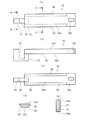
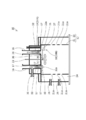
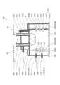
- FIG. 1 It is a schematic diagram of the abatement apparatus shown as embodiment of this invention, (a) is a figure which shows the structure of the mechanism part, (b) is a figure which shows the block structure of the control part. It is the top view which looked at the inred head and its peripheral structure in the abatement apparatus same as the above from the combustion chamber side.
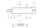
- the scraper in the same abatement apparatus is shown, (a) is a plan view of the scraper, (b) is a side view of the scraper, (c) is a bottom view of the scraper, and (d) is an A- in FIG. A sectional view taken along line A, (e) is a sectional view taken along line BB in (a).
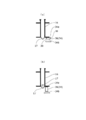
- FIG. 2 is a diagram for explaining the effect of the scraper shape in the abatement apparatus shown in FIG. 1 in comparison with the conventional structure, in which (a) is a diagram in the case of the scraper shape in the present invention device, and (b) is the conventional scraper shape.
- FIG. FIG. 2 shows a modification of the scraper, in which (a) is a bottom view of the scraper, and (b) is a cross-sectional view taken along the line CC in (a).
- FIG. 9 shows still another modified example of the scraper, wherein (a) is a bottom view of the scraper, and (b) is a sectional view taken along the line DD in (a).
- An object of the present invention is to provide a detoxifying device that can easily and quickly scrape off deposits deposited on the inner wall of the gas passage to be treated and the wall surface of the combustion chamber.
- a detoxification device for detoxifying a target gas containing harmful components by burning or thermally decomposing it in a combustion chamber wherein the gas introduction hole outlet for introducing the target gas into the combustion chamber is provided.
- the gas passage on the top surface of the combustion chamber and the deposit adhering to the gas passage are moved up and down in the gas passage to remove the deposit from the gas introduction hole outlet and enter the combustion chamber.
- Deposit removing means, and the first deposit removing means and the front So as not to interfere with a second deposit removal means is realized with the construction in which a driving device, for driving the first and sediment removal unit the second deposit removal means.
- FIG. 1 is a schematic diagram of an abatement apparatus 10 shown as an embodiment of the present invention, where (a) shows the configuration of the mechanism unit and (b) shows the block configuration of the control unit.
- the abatement apparatus 10 of FIG. 1 is a combustion-type abatement apparatus.
- an exhaust gas containing harmful components exhausted from a process chamber of a known semiconductor manufacturing apparatus is used as a process gas PG, and the process gas PG.
- PG an exhaust gas containing harmful components exhausted from a process chamber of a known semiconductor manufacturing apparatus
- the process gas PG is used as a means for detoxification by combustion or thermal decomposition
- exhaust gas containing harmful components exhausted from an apparatus other than a semiconductor manufacturing apparatus is similarly used as a means for detoxification as the gas to be treated PG.
- the detoxifying device 10 forms a detoxifying device body 12 having a combustion chamber 11 into which the above-described exhaust gas containing harmful components, that is, a gas to be treated PG, and a flame necessary for detoxification are formed in the combustion chamber 11.
- Burner 13 pilot burner 14 that forms a seed fire PL necessary for ignition of the burner 13, nozzle 16 as a gas passage for introducing the gas PG to be processed into the combustion chamber 11, and the inner wall of the combustion chamber 11 and its surroundings
- the device controller 20 is a computer, for example, and incorporates a program for operating the operation of the entire device according to a predetermined procedure.
- the abatement apparatus main body 12 includes a first cylindrical wall 21 having a substantially cylindrical shape and a second cylindrical wall 22 having a substantially cylindrical shape which is installed outside the first cylindrical wall 21.
- the upper surfaces (top surfaces) of the cylindrical wall 21 and the second cylindrical wall 22 are closed by an inred head 23, and the lower surface (bottom surface) is closed by a bottom wall (not shown).
- the internal space of the 1st cylinder wall 21 is comprised as the combustion chamber 11, and the burner into which a combustible fuel and air are introduce
- the gas chamber 24 is configured. Note that the first cylindrical wall 21 and the second cylindrical wall 22 are not necessarily cylindrical.
- a burner 13 that forms a flame necessary for detoxification in the combustion chamber 11 is provided in a first burner 13A provided in the burner gas chamber 24 and an inred 23 constituting the top wall of the combustion chamber 11. And a second burner 13B.
- a base portion 23A (hereinafter referred to as “the top surface 23A of the combustion chamber 11”) of the inred head 23 forming the top surfaces of the first and second cylindrical walls 21 and 22 is as shown in FIG.
- the first cylindrical wall 21 and the second cylindrical wall 22 are formed in a disc shape in accordance with the cylindrical shape.
- the second burner 13B, the deposit removing means 18, the temperature sensor 19, and the pilot burner 14 are attached to the base portion 23A of the inred head 23.
- the first burner 13 ⁇ / b> A has a plurality of ejection holes 21 a formed in the first cylindrical wall 21 constituting the burner gas chamber 24, and combustible fuel 25 and air 26 are directed from the ejection holes 21 a toward the combustion chamber 11.
- the air-fuel mixture 27 is ejected and combusted. Therefore, the second cylinder wall 22 has a first combustion-supporting gas supply nozzle 28 that supplies the combustible fuel 25 into the burner gas chamber 24, and a second gas that supplies air 26 into the burner gas chamber 24.
- a combustion-supporting gas supply nozzle 29 is connected.
- the second burner 13B has a gas nozzle 16 as a gas passage for introducing the gas PG to be processed into the combustion chamber 11.
- the outlet side of the nozzle 16 for gas to be processed is opened as a gas introduction hole outlet 16 ⁇ / b> A on the lower surface of the inred head 23, that is, the top surface 23 ⁇ / b> A of the combustion chamber 11.
- An inlet side of the gas to be processed nozzle 16 is connected to an outlet side of an exhaust system (not shown) that discharges the gas to be processed PG. Therefore, in the abatement apparatus 10, the gas to be processed PG is introduced into the combustion chamber 11 from the nozzle 16 for gas to be processed.
- the number of gas nozzles 16 to be processed is not particularly limited.
- nozzles 16 are provided as shown in FIG. 2, and these four nozzles 16 are arranged on the reference circle C1 at substantially equal intervals. Yes.
- another third combustion-supporting gas supply nozzle 30 is connected in the middle of the nozzle for processing gas 16, and the gas to be processed is connected from the connected third combustion-supporting gas supply nozzle 30.
- the pilot burner 14 has a pilot nozzle 14 ⁇ / b> A disposed in the vicinity of the gas nozzle 16 to be processed.
- the outlet side of the pilot nozzle 14A is opened to the top surface of the combustion chamber 11, and a mixture of combustible fuel and air (or oxygen) is jetted from the outlet of the pilot nozzle 14A toward the combustion chamber, It has a structure that allows combustion.
- the base portion 23A of the inred head 23 where the pilot burner 14 is disposed, that is, the position provided on the top surface 23A of the combustion chamber 11 is provided with a gas introduction hole outlet 16A in the combustion chamber 11. Is provided outside the reference circle C1.
- the temperature sensor 19 measures the temperature in the combustion chamber 11, has a pin shape, and is attached to the inred head 23 with one end projecting into the combustion chamber 11.
- the position on the top surface 23A of the combustion chamber 11 where the temperature sensor 19 is disposed is also located outside the reference circle C1 where the gas introduction hole outlet 16A is disposed in the combustion chamber 11. ing.
- the deposit removing means 18 includes first deposit removing means 18A for discharging and removing the deposit 17 adhering in the gas to be treated nozzle (gas passage) 16 from the gas introduction hole outlet 16A into the combustion chamber 11.
- the second deposit removing means 18B for removing the deposit 17 attached to the top surface 23A of the combustion chamber 11 is provided.
- the first deposit removing means 18A has a cleaning head 32 as a scraper wound in a coil spring shape.
- the cleaning head 32 is disposed in the gas to be processed nozzle (gas passage) 16 so as to be able to reciprocate in the direction in which the gas to be processed PG flows (hereinafter referred to as “gas passage direction”), that is, in the vertical direction. ing.
- the cleaning head 32 is configured to scrape and remove the deposit 17 fixed to the inner wall of the gas nozzle 16 to be processed when reciprocating up and down in the gas nozzle 16 (gas passage).
- the head tip portion 32a of the cleaning head 32 protrudes from the gas introduction hole outlet 16A into the combustion chamber 11, and the deposit 17 scraped off in the gas nozzle 16 to be treated is removed.
- the configuration is such that it can be reliably discharged into the combustion chamber 11.
- the cleaning head 32 does not necessarily have a structure wound around a coil spring as long as the deposit 17 fixed to the inner wall of the gas nozzle 16 can be removed by the movement of the gas nozzle 16. May be. Further, although the cleaning head 32 may be moved manually, in this embodiment, the cleaning head 32 is automatically operated by the operation of the drive unit 118a having a driving force of an electric motor (not shown) driven and controlled by the apparatus controller 20. It is the composition which becomes.
- the second deposit removing means 18B has a rotatable shaft 33 penetrating substantially the center of the inred head 23 and a scraper 34 attached to the lower end side of the shaft 33 so as to be integrally rotatable.
- the scraper 34 is attached to the lower end portion of the shaft 33 so as to slide on the lower surface of the inred head 23, that is, the top surface 23 ⁇ / b> A of the combustion chamber 11.
- the rotation of the shaft 33, that is, the rotation of the scraper 34 may be manual, but in the present embodiment, the operation of the drive unit 118b using the electric motor (not shown) driven and controlled by the apparatus controller 20 as a driving force, It is configured to operate automatically.
- the “rotation” in the present embodiment refers to the approximate center of the inred head 23 (that is, the inred head 23 is connected to the shaft 33). Is defined as an angular motion in the range of 1 to 360 degrees centered on the point). Therefore, a reciprocating motion in which the trajectory (operating area) of the scraper 34 has a fan shape and a motion in which the axis 33 is provided around the center of the scraper 34 are included.
- the scraper 34 that rotates as described above has a gas introduction hole outlet 16 ⁇ / b> A when the cleaning head 32 provided in the gas nozzle 16 to be reciprocated in the vertical direction protrudes into the combustion chamber 11. If it is going to cross the part which opposes, it will contact the head front-end
- the scraper 34 comes into contact with the temperature sensor 19 provided on the surface of the base portion 23 ⁇ / b> A of the inred head 23 so as to protrude into the combustion chamber 11.
- the screper 34 crosses the gas introduction hole outlet 16A under the control of the apparatus controller 20 because the head tip portion 32a of the cleaning head 32 is retracted into the gas nozzle 16 to be treated and burned.
- the apparatus controller 20 sets the timing of the rotation of the scraper 34 and the movement of the cleaning head 32 so that the state does not protrude into the chamber 11.
- the apparatus controller 20 controls the scraper 34 to remove the deposit 17 after the cleaning head 32 finishes removing the deposit 17.
- the upper surface 34a A contact avoiding portion 35 that is a concave space / gap is provided on the surface facing the top surface 23A.
- the shape of the contact avoiding portion 35 can be appropriately changed according to the size and shape of the temperature sensor 19 provided on the base portion of the inred 23 (the top surface of the combustion chamber 11).
- the detailed configuration of the scraper 34 has a main body 36 formed as an elongated plate-like member, as shown in FIGS.
- One end of the main body 36 has a long hole 34c into which the shaft 33 is inserted.
- the shaft 33 is inserted into the long hole 34c, and then a nut 39 is attached to the shaft 33 from the lower surface 34b side of the scraper 34. It is configured to be fixed to the shaft 33 by being attached and tightened.
- the other end side of the scraper 34 has a head portion 37 provided with the contact avoiding portion 35, and the contact avoiding portion 35 is formed on the head portion 37.
- the main body 36 rotates within the reference circle C1 depicted in FIG. 2 (including the entire gas introduction hole outlet 16A), and between the reference circle C1 and the rotation locus circle C2 similarly depicted in FIG. This is rotated by the temperature sensor 19).
- the main body portion 36 of the scraper 34 is a cross-sectional view taken along the line AA in FIG.
- inclined surface portions 38 that are inclined from the lower surface 34b toward the upper surface 34a (a flat portion formed in parallel with the top surface 23A), and acute edges are formed on both side edges in the short direction.
- the inclined surface portions 38 provided on both sides in the short direction of the main body portion 36 are formed in a tapered shape (wedge shape) with a cross-sectional shape inclined at an acute angle toward the rotation direction.
- FIG. 4 is an operation explanatory view of the abatement apparatus 10. The operation of the combustion type abatement apparatus shown in FIGS. 1 to 3 will be described with reference to the operation explanatory diagram of FIG.
- the abatement apparatus 10 forms a seed fire PL in the combustion chamber 11 by the pilot burner 14, as shown in FIG. This seed fire PL is set so that the ignition state is always maintained.
- combustible fuel is supplied from the first combustion-supporting gas supply nozzle 28 to the first burner 13A, and air is supplied from the second combustion-supporting gas supply nozzle 29.
- the combustible fuel 25 and the combustion-supporting gas (air 26) supplied to the first burner 13A become an air-fuel mixture 27 and are ejected from the first burner 13A toward the combustion chamber 11.
- the igniting action of the pilot burner 14 by the seed fire PL is applied to the jetted air-fuel mixture 27, and a flame necessary for detoxifying the gas to be processed PG is formed in the combustion chamber 11.
- the gas to be treated PG supplied to the combustion chamber 11 is supplied from the third combustion-supporting gas supply nozzle 30 together with the combustion-supporting gas (air or oxygen) after the formation of the flame.
- the toxic gas is changed into a harmless gas by causing an oxidation reaction in which the gas to be treated PG is burned and reacted with air (oxygen) in the combustion chamber 101.
- the to-be-processed gas PG detoxified by the combustion or thermal decomposition by a flame is discharged
- the apparatus controller 20 drives the deposit removing means 18 periodically or as necessary, and the nozzle for the gas to be processed (gas The deposit 17 deposited and deposited in the (passage) 16 and the deposit 17 deposited and deposited in the vicinity of the gas nozzle 16 (gas passage) 16 in the combustion chamber 11 are removed.
- the first deposit removing means 18A and the second deposit removing means 18B are operated.
- the deposit 17 deposited on the gas nozzle 16 (gas passage) to be treated is removed by the apparatus controller 20 controlling the drive unit 118a, and the drive unit 118a performs cleaning in the first deposit removing means 18A.
- the head 32 is reciprocated in the gas passage direction, that is, in the vertical direction, in the gas to be treated nozzle (gas passage) 16 to scrape and remove the deposit 17 adhered to the inner wall of the gas nozzle 16 to be treated.
- the head tip portion 32a of the cleaning head 32 protrudes from the gas introduction hole outlet 16A into the combustion chamber 11 and is scraped off in the gas nozzle 16 to be processed.
- the deposit 17 is discharged into the combustion chamber 11.
- the deposit 17 deposited and deposited on the top surface 23 ⁇ / b> A of the combustion chamber 11 is controlled by the apparatus controller 20 after the cleaning of the gas nozzle 16 to be processed by the cleaning head 32 is finished. Then, the drive unit 118b is driven, the drive unit 118b rotates the shaft 33, and the scraper 34 is rotated together with the shaft 33 so as to slide on the top surface 23A of the combustion chamber 11, and the scraper 34 is rotated on the top surface of the combustion chamber 11. The deposit 17 adhering to and depositing on 23A is removed.
- the scraper 34 When the scraper 34 is rotated under the control of the apparatus controller 20, the scraper 34 scrapes off the deposit 17 deposited on the top surface 23A side of the combustion chamber 11. At this time, the main body portion 36 of the scraper 34 is formed with an inclined surface portion 38 having a wedge shape in cross section formed at an acute angle on the side surface on the rotating side. Therefore, when the scraper 34 rotates while sliding on the top surface 23A, the inclined surface portion 38 scrapes off the deposit 17 on the top surface 23A. Even if the temperature sensor 19 is disposed on the trajectory of the rotational movement in the middle, the contact avoiding portion 35 escapes and scraping of the deposit 17 can proceed without interfering with the temperature sensor 19.
- the apparatus controller 20 controls the timing of the rotation of the scraper 34 and the movement of the cleaning head 32 for each of the four cleaning heads 32, that is, the scraper 34 serves as the gas introduction hole outlet.
- the head tip portion 32a of the cleaning head 32 is retracted from the combustion chamber 11 into the gas introduction hole outlet 16A, and after the scraper 34 passes under the gas introduction hole outlet 16A, the inside of the combustion chamber 11 again.
- the scraper 34 and the cleaning head 32 can be operated at the same time if the scraper 34 and the cleaning head 32 are prevented from coming into contact with each other.
- the abatement apparatus 10 according to the present embodiment, contact between the scraper 34 and the cleaning head 32 is avoided, so that the cleaning head 32 adheres to the inner wall of the gas nozzle 16 (gas passage) 16 to be processed.
- the operation of removing the deposit 17 and the operation of removing the deposit 17 adhering to the top surface 23A of the combustion chamber 11 by the scraper 34 can be continuously processed in a short time, and the maintenance time can be shortened. Improvement in productivity can be expected.
- the short direction of the scraper 34 of the deposit removing means faces the top surface 23A and is parallel to the top surface 23A. It has a formed flat portion (upper surface 34a) and an inclined surface portion 38 formed to be inclined toward the flat portion (upper surface 34a), and the cross-sectional shape of the scraper 34 in the short direction is an acute angle toward the rotation direction side. It is formed in a tapered shape. Accordingly, when the scraper 34 is rotated horizontally, the scraper 34 can be scraped off in such a manner that the sharp tip portion of the scraper 34 bites into the deposit 17 and cuts the deposit 17. However, the deposit 17 can be removed smoothly. Thereby, the removal operation of the deposit 17 adhering to the top surface 23A of the combustion chamber 11 by the scraper 34 can be processed in a short period of time, and the maintenance time can be shortened and the productivity can be expected to be improved.
- the deposit 17 discharged to the combustion chamber 11 side by the cleaning head 32 becomes a dome shape and becomes the outlet of the gas introduction hole.
- the scraper 34 scrapes off the deposit 17 at the gas introduction hole outlet 16A, the deposit 17 is pushed back from the gas introduction hole outlet 16A into the gas to be treated (gas passage) 16. There is a risk of closing the gas introduction hole outlet 16A.
- FIG. 5B shows that the deposit 17 discharged to the combustion chamber 11 side by the cleaning head 32 becomes a dome shape and becomes the outlet of the gas introduction hole.
- the shape of the both-sides part of the transversal direction of the scraper 34 is a continuous inclined surface part (acute angle) from the lower surface 34b to the terminal of the upper surface 34a (plane part formed in parallel with the top surface 23A), respectively.
- the structure in which the edge) 38 is formed is disclosed, for example, as shown in FIG. 6, a deformed structure having a substantially semicircular cross section with the lower surface 34b side as a curved surface may be used. Even in this structure, since the cross-sectional shape of both ends in the short direction is formed in a tapered shape, when scraping the deposit 17 from the top surface 23A, the scraper 34 scrapes the deposit 17 from the top surface 23A. Can be taken.
- both side portions of the scraper 34 in the short direction is substantially perpendicular to the upper surface 34a in the middle of the inclined surface portion 38 without forming the inclined surface portion 38 up to the end of the upper surface 34a, as shown in FIG.
- the structure may be provided with the contact surface 39 formed on the surface.
- This abutting surface 39 is in a state where the one side portion (terminal) is thick when one side portion in the short side direction of the main body portion 36 abuts on the deposit 17. It is possible to prevent a part of one side portion in the short direction of the scraper 34 from being lost.
- both ends in the lateral direction are formed in a tapered shape, when scraping off the deposit 17 from the top surface 23a, the scraper 34 scrapes off the deposit 17 from the top surface 23a. be able to.
- the scraper 34 may have a structure in which the inclined surface portion 38 is provided only on one side in the short direction, that is, on the rotation direction side.
- the deposit removing means 18 and the second deposit removing means 18b which are composed of the first deposit removing means 18A and the second deposit removing means 18B, are used in the abatement apparatus 10 in this embodiment. In addition, it can be used for other abatement devices similar to this.
Landscapes
- Engineering & Computer Science (AREA)
- Mechanical Engineering (AREA)
- General Engineering & Computer Science (AREA)
- Environmental & Geological Engineering (AREA)
- Incineration Of Waste (AREA)
- Gasification And Melting Of Waste (AREA)
Abstract
【課題】被処理ガス通路の内壁、及び、燃焼室の壁面に付着して堆積した堆積物を簡単に、かつ、短期間で掻き落として除去することができる除害装置及び除害装置に用いられる堆積物除去手段を提供する。 【解決手段】燃焼室11内に被処理ガスPGを導入するガス導入孔出口16Aを燃焼室11の天面23Aに配設した被処理ガス用ノズル16と、被処理ガス用ノズル16内に付着している堆積物17を、被処理ガス用ノズル16内を上下に移動してガス導入孔出口16Aから燃焼室11内に排出除去する清掃ヘッド32と、燃焼室11内にて天面23Aと対向して水平回転可能に配設され、燃焼室11の天面23に付着している堆積物を除去するスクレイパー34と、清掃ヘッド32とスクレイパー34が干渉しないように、清掃ヘッド32とスクレイパー34を駆動させる駆動装置と、を備える。
Description
本発明は被処理ガス中の有害成分を燃焼室内で燃焼又は熱分解して無害化する除害装置及び除害装置に用いられる堆積物除去手段に関するものであり、特に、燃焼室周辺に付着した堆積物を簡単に除去することができるようにした除害装置及び除害装置に用いられる堆積物除去手段に関するものである。
従来、例えば、半導体製造工場では、周知の半導体製造装置のプロセスチャンバから排気される有害成分含有の排気ガスを無害化する手段として、燃焼式の除害装置を使用している(例えば、特許文献1参照)。
図9は、従来の除害装置の模式図である。この図9の除害装置100は、有害成分含有の排気ガスを被処理ガスとして燃焼室内に導入し、その燃焼室内で燃焼または熱分解して無害化する装置(燃焼式)である。
図9を用いて従来の除害装置100の概略構成を説明すると、除害装置100は、被処理ガスが導入される燃焼室101を備えた除害装置本体102と、無害化に必要な火炎を燃焼室101内に形成するバーナー103と、バーナー103の点火に必要な種火PLを形成するパイロットバーナー104と、支燃性ガス供給手段105と、を有している。なお、支燃性ガス供給手段105は、火炎の形成に必要な可燃性燃料111を第1の支燃性ガスとしてバーナー103に供給する第1のバーナー対応支燃性ガス供給手段105Aと、火炎の形成に必要な空気(または酸素)112または酸素を第2の支燃性ガスとしてバーナー103に供給する第2のバーナー対応支燃性ガス供給手段105Bとを有している。
また、除害装置100の除害装置本体102は、第1の筒壁106の外側に第2の筒壁107を設置した構造になっており、その第1の筒壁106の内側空間部を燃焼室101として構成してある。さらに、第1の筒壁106と第2の筒壁107との間の空間部は、可燃性燃料と空気が導入されるバーナーガス室108として構成してある。
さらに、図9の除害装置100は、被処理ガス(排気ガス)PGを燃焼室101に導入する手段として、ノズル109を有している。このノズル109の出口(ガス導入孔出口)側109aは、燃焼室101の天面101aに開口している。また、ノズル109の入口側は、被処理ガスPGの図示しない排気系の出口側に接続してある。このことから、図9の除害装置100では、ノズル109から燃焼室101に被処理ガスPGが導入される。なお、そのノズル109の本数は、特に限定されず、1本でも、または2本以上の場合もある。
また、除害装置100は、バーナー103として、第1のバーナー103Aと第2のバーナー103Bを有している。第1のバーナー103Aは、バーナーガス室108を構成する第1の筒壁106に噴出孔106aを複数開設し、その噴出孔106aから燃焼室101に向けて可燃性燃料111と空気(または酸素)112の混合気113を噴出し、燃焼可能とする構造になっている。一方、第2のバーナー103Bは、先に説明したノズル109の途中に別のノズル110を接続し、接続したノズル110からノズル109に対して可燃性燃料111と空気(または酸素)112を供給することにより、ノズル109の出口から燃焼室101に向けて可燃性燃料111と空気(または酸素)の混合気114を噴出し、燃焼可能とする構造になっている。
そして、図9の除害装置100は、図示しない装置コントローラから装置起動信号が与えられると、パイロットバーナー104による種火PLが燃焼室101内に形成される。この種火PLは、常にその点火の状態が維持されるように設定してある。
また、支燃性ガス供給手段105からバーナー103に対して第1の支燃性ガスと第2の支燃性ガスの供給が開始される。この各支燃性ガスの供給は、具体的には、第1のバーナー対応の支燃性ガス供給手段105Aから第1のバーナー103Aに対して第1の支燃性ガス(可燃性燃料)と第2の支燃性ガス(空気)が供給され、第2のバーナー対応の支燃性ガス供給手段105Bから第2のバーナー103Aに対して空気(または酸素)112が供給され、さらにノズル110から可燃性燃料111と空気(または酸素)112が供給される。
バーナー103(103A、103B)に対して供給された第1の支燃性ガスと第2の支燃性ガスは、それぞれ混合気113、114となってバーナー103(103A、103B)から燃焼室101に向けて噴出する。そして、噴出した混合気113、114に対してパイロットバーナー104での種火PLによる引火作用が加わり、燃焼室101内には被処理ガスの無害化に必要な火炎が形成される。
なお、燃焼室101への被処理ガスPGの供給は、火炎の形成後に、ノズル109を介して行われる。そして、この除害装置100では燃焼室101内において、被処理ガスPGを燃やして空気(酸素)と反応させる酸化反応を起こすことで、有毒ガスを無害なガスに変えている。そして、火炎による燃焼または熱分解により無害化した被処理ガスは、処理ガスとして、燃焼室101に連通する図示しない出口ポートから除害装置本体102外に排出される。
また、反対に、図示しない装置コントローラから図9の除害装置100に対して燃焼(熱分解)停止の指示信号が与えられると、支燃性ガス供給手段105(105A、105B)からバーナー103(103A、103B)に対する第1の支燃性ガス(可燃性燃料)及び第2の支燃性ガス(可燃性燃料)の供給が各々停止することで、燃焼室101内の火炎は自然鎮火する。そして、火炎の自然鎮火によって、燃焼室101内での火炎による被処理ガスPGの燃焼または熱分解も停止する。
ところで、半導体製造装置での除害装置の場合、燃焼室内で有害成分含有の被処理ガス(排気ガス)を燃やして空気(酸素)と反応させることで無害なガスに変えると、例えば被処理ガスがシランガス(SiH4)であれば、酸化反応の結果、無害な二酸化ケイ素;シリカ(SiH2)が発生する。このシリカは固体・粉末であり、酸化反応によってシリカに変化する際にエネルギーが与えられ、酸化反応を起こす空間である燃焼室の空間を飛散する。つまり、真っ直ぐに落下せずに飛散するので、その多くが燃焼室の壁面、並びに、燃焼室に被処理ガスを導入するためのノズル内及びその近傍に付着し、また時間の経過とともに堆積してしまう。そのため、その堆積物を取り除くのに定期的なメンテナンス(オーバーホール)の実施が必要となる。
そこで、被処理ガスを燃焼室に導入するガス導入孔出口付近に堆積した堆積物を機械的に取り除く技術として、特許文献2、特許文献3に記載されているような除去装置などが従来から知られている。
特許文献2には、折り畳み可能なL字形状の掻き取りヘッドを有する掻き取り器を被処理ガス通路内に配設している。また、掻き取りヘッドの先端部が燃焼室内の空間まで挿入された際に、燃焼室内でL字状に拡開するようになっている。そして、掻き取りヘッドの先端部が燃焼室内で拡開したら、その拡開した状態で、その先端部と共に掻き取り機を回転させると、燃焼室の開口周囲の内壁面に固着されている堆積物と被処理ガス通路内の壁面に固着されている堆積物を機械的に除去できるようになっている。しかしながら、特許文献2の構成では、開口周囲において、燃焼室の内壁面から突出させた状態で温度センサを配設したい場合には、温度センサが掻き取りヘッドの回転の妨げとなる。
そこで、特許文献3には、掻き取りヘッドが温度センサを避けて回転しながら、燃焼室の内壁面に固着した堆積物を機械的に除去できるようにした構成が開示されている。
しかしながら、特許文献3記載の発明は、燃焼室の内壁面に固着した堆積物を機械的に除去する構成は開示されているが、被処理ガス通路内の壁面に固着した堆積物も同時に除去する構成は開示されていない。
また、一般的に、燃焼室の内壁面に固着した堆積物と被処理ガス通路内の壁面に固着した堆積物を機械的に除去するためのメンテナンスは、三ヶ月に一度程度の頻度で実施されるが、運用面・費用面を鑑みたときに、メンテナンス時間は短ければ短い方がよい。
したがって、燃焼室の開口周囲の内壁面に固着した堆積物の機械的な除去と被処理ガス通路内の壁面に固着した堆積物の機械的な除去を短期間で行うことができる除害装置が求められている。
また、半導体製造プロセスで使用される除害装置の場合、ノズル(被処理ガス通路)の内壁、及び、燃焼室の壁面に付着して堆積したシリカは、時間の経過とともに固化し、除去をするのに比較的大きな力を必要とする。そのため、一度堆積してしまうと、その堆積物を取り除くのに大きな掻き取り力が必要となり掻き取りづらく、また掻き取りヘッドも破損し易く、掻き取りヘッドを頻繁に交換しなければならないと言う問題点があった。したがって、堆積物を簡単に、かつ短期間で掻き取ることができる除害装置が望まれている。
そこで、燃焼室の壁面に付着して堆積した堆積物を簡単に、かつ、短期間で掻き落として除去することができる除害装置及び除害装置に用いられる堆積物除去手段を提供するために解決すべき技術的課題が生じてくるのであり、本発明はこの課題を解決することを目的とする。
本発明は上記目的を達成するために提案されたものであり、請求項1に記載の発明は、有害成分を含む被処理ガスを燃焼室で燃焼または熱分解することにより無害化する除害装置であって、前記燃焼室に前記被処理ガスを導入するガス導入孔出口を前記燃焼室の天面に有するガス通路と、前記ガス通路に付着している堆積物を、前記ガス通路の中を上下に移動して前記ガス導入孔出口から前記堆積物を除去し前記燃焼室に排出する第1の堆積物除去手段と、前記燃焼室にて前記天面と対向して水平回転可能に配設され、前記燃焼室の前記天面に付着している堆積物を除去する第2の堆積物除去手段と、前記第1の堆積物除去手段と前記第2の堆積物除去手段が干渉しないように、前記第1の堆積物除去手段と前記第2の堆積物除去手段を駆動させる駆動装置、を備える除害装置を提供する。
この構成によれば、前記ガス通路側の内壁に堆積した堆積物は、前記ガス通路の中を上下に移動する前記第1の堆積物除去手段により、前記ガス導入孔出口から前記燃焼室に排出されて除去される。一方、前記燃焼室の前記天面に付着した堆積物は、前記燃焼室内にて前記天面と対向して水平回転する前記第2の堆積物除去手段の回転による掻き落としにより除去される。そして、第1の堆積物除去手段により前記堆積物を除去する駆動と前記第2の堆積物除去手段により前記堆積物を除去の駆動を、駆動装置により、前記第1の堆積物除去手段と前記第2の堆積物除去手段が干渉しないように、第1の堆積物除去手段と前記第2の堆積物除去手段を駆動させることにより、前記第1の堆積物除去手段が前記第2の堆積物除去手段の回転の妨げになるのを防ぐことができる。これらより、前記第1の堆積物除去手段による前記ガス通路内の内壁に付着した堆積物の除去動作と、前記第2の堆積物除去手段による前記燃焼室の前記天面に付着した前記堆積物の除去動作を、連続して短期間に処理することができる。
請求項2に記載の発明は、請求項1に記載の構成において、前記駆動装置は、前記第2の堆積物除去手段が前記ガス導入孔出口の下を通過している時に前記第1の堆積物除去手段が前記ガス導入孔出口から突出しないように前記第1の堆積物除去手段を上下移動させる、除害装置を提供する。
この構成によれば、前記第2の堆積物除去手段が前記ガス導入孔出口の下を通過している時に前記第1の堆積物除去手段が前記ガス導入孔出口から突出しないようにしているので、前記第1の堆積物除去手段と前記第2の堆積物除去手段との干渉をさらに確実に防ぐことができる。
請求項3に記載の発明は、請求項1に記載の構成において、前記駆動装置は、前記第1の堆積物除去手段が前記ガス導入孔出口から突出している時に前記第2の堆積物除去手段が前記ガス導入孔出口の下を通過しないように前記第2の堆積物除去手段を前記水平回転させる、の除害装置を提供する。
この構成によれば、前記第1の堆積物除去手段が前記ガス導入孔出口から突出している時に前記第2の堆積物除去手段が前記ガス導入孔出口の下を通過しないように前記第2の堆積物除去手段を前記水平回転させるようにしているので、前記第1の堆積物除去手段と前記第2の堆積物除去手段との干渉をさらに確実に防ぐことができる。
請求項4に記載の発明は、請求項1、2又は3に記載の構成において、前記駆動装置は、前記第1の堆積物除去手段の前記上下の移動を制御する装置コントローラを備える、除害装置を提供する。
この構成によれば、前記装置コントローラを使用して、前記第1の堆積物除去手段の前記上下の移動を、前記第2の堆積物除去手段の水平回転移動に合わせて簡単に制御することができる。
請求項5に記載の発明は、請求項1、2、3又は4に記載の構成において、前記駆動装置は、前記第1の堆積物除去手段が前記堆積物の除去を終えた後に、前記第2の堆積物除去手段が前記堆積物の除去を行うように制御する、除害装置を提供する。
この構成によれば、前記第2の堆積物除去手段が前記堆積物の除去を行う時、前記第1の堆積物除去手段が前記ガス通路側から前記燃焼室側の天面に排出した堆積物も同時に除去することができる。
請求項6に記載の発明は、請求項1、2、3、4又は5に記載の構成において、前記燃焼室内の前記天面において、前記燃焼室内の温度を検出する温度センサを前記燃焼室内に突出して設け、前記第2の堆積物除去手段は、前記温度センサと対向する前記平面側で前記温度センサと交差する部分に、前記第2の堆積物除去手段の回転時に前記温度センサとの接触を避ける接触回避部を設けてなる、除害装置を提供する。
この構成によれば、前記第2の堆積物除去手段には、前記温度センサと対向する前記平面側で前記温度センサと交差する部分に、前記第2の堆積物除去手段の回転時に前記温度センサとの接触を避ける接触回避部を設けている。したがって、前記燃焼室内の温度を検出する前記温度センサを、例え前記燃焼室の天面に前記燃焼室内に突出させて設けても、前記第2の堆積物除去手段は、前記温度センサに干渉することなく、前記燃焼室の前記天面における前記温度センサ近傍を含めた前記ガス導入孔出口付近に付着した前記堆積物を定期的に除去(掻き取る)ことができる。また、前記ガス通路内の内壁に付着する堆積物と、温度センサ近傍を含めた前記燃焼室の前記天面に付着した堆積物を定期的に除去することができるので、前記ガス通路内壁や前記燃焼室の前記天面のメンテナンス周期を長くすることができる。また、前記温度センサを、前記燃焼室内において前記ガス導入孔出口よりも外側の位置に設けたことにより、前記ガス導入孔出口の設置位置の自由度が得られるとともに、前記第2の堆積物除去手段の構成を簡略化することができる。
請求項7に記載の発明は、有害成分を含む被処理ガスを燃焼室で燃焼または熱分解することにより無害化する除害装置であって、前記燃焼室に前記被処理ガスを導入するガス導入孔出口を前記燃焼室の天面に有するガス通路と、前記燃焼室にて前記天面と対向して水平回転可能に配設され、前記燃焼室の前記天面に付着している堆積物を除去する堆積物除去手段と、を備え、前記堆積物除去手段は、前記天面と対向して前記天面と平行に形成された平面部と少なくとも一部に前記平面部に向かって傾斜して形成された傾斜面部とを有し、断面形状が回転方向に向かって先細状に形成された、除害装置を提供する。
この構成によれば、前記燃焼室の前記天面に付着した前記堆積物は、前記燃焼室の前記天面と対向して水平回転する前記堆積物除去手段の回転による掻き落としにより除去される。そして、前記堆積物除去手段が、前記天面と対向して前記天面と平行に形成された前記平面部と、少なくとも一部に前記平面部に向かって傾斜して形成された前記傾斜面部を有して、断面形状が回転方向に向かって先細状に形成されている。したがって、前記堆積物除去手段の水平回転時に、前記堆積物除去手段の先細状の部分が前記堆積物内―徐々に喰い込んで、前記堆積物を切り削る形で掻き取ってスムーズに除去することができる。
請求項8に記載の発明は、請求項7に記載の構成において、前記傾斜面部は、前記断面形状が鋭角をなす楔状に形成されている、除害装置を提供する。
この構成によれば、前記堆積物除去手段の先細状の部分における前記断面形状が鋭角をなす楔状に形成されている。したがって、前記堆積物除去手段の水平回転時に、前記堆積物除去手段の先細状の部分が前記堆積物内へ徐々に喰い込んでスライスする形で、前記堆積物を掻き取り、簡単に除去することができる。
請求項9に記載の発明は、請求項7に記載の構成において、前記傾斜面部は、前記断面形状が概略半円形にして曲面で形成されている、除害装置を提供する。
この構成によれば、前記堆積物除去手段の先細状の部分における前記断面形状が概略半円形に形成されている。したがって、前記堆積物除去手段の水平回転時に、前記堆積物除去手段の先細状の部分が前記堆積物内に喰い込んでスライスする形で、前記堆積物を掻き取り、簡単に除去することができる。
請求項10に記載の発明は、請求項7、8、又は9に記載の構成において、前記傾斜面部は、前記堆積物と交差する部分に、前記堆積物と面接触になる当接面を設けてなる、除害装置を提供する。
この構成によれば、前記傾斜面部は、前記堆積物と交差する部分に、前記堆積物と面接触になる当接面を設けて、前記堆積物と交差する部分を肉厚に形成して強度を高めている。これにより、先端部が前記堆積物と面接触した際に前記傾斜面部の先端が破損するのを防止することができ、前記堆積物除去手段の寿命を向上させることができる。
請求項11に記載の発明は、請求項7、8、9又は10に記載の構成において、前記燃焼室内の天面で、かつ前記ガス導入孔出口よりも外側の位置において、前記燃焼室内の温度を検出する温度センサを前記燃焼室内に突出して設け、前記第2の堆積物除去手段は、前記温度センサと対向する前記平面側で前記温度センサと交差する部分に、前記第2の堆積物除去手段の回転時に前記温度センサとの接触を避ける接触回避部を設けてなる、除害装置を提供する。
この構成によれば、前記第2の堆積物除去手段には、前記温度センサと対向する前記平面側で前記温度センサと交差する部分に、前記第2の堆積物除去手段の回転時に前記温度センサとの接触を避ける接触回避部を設けている。したがって、前記燃焼室内の温度を検出する前記温度センサを、例え前記燃焼室の天面に前記燃焼室内に突出させて設けても、前記第2の堆積物除去手段は、前記温度センサに干渉することなく、前記燃焼室の前記天面における前記温度センサ近傍を含めた前記ガス導入孔出口付近に付着した前記堆積物を定期的に除去(掻き取る)ことができる。また、前記ガス通路内の内壁に付着する堆積物と、温度センサ近傍を含めた前記燃焼室の前記天面に付着した堆積物を定期的に除去することができるので、前記ガス通路内壁や前記燃焼室の前記天面のメンテナンス周期を長くすることができる。また、前記温度センサを、前記燃焼室内において前記ガス導入孔出口よりも外側の位置に設けたことにより、前記ガス導入孔出口の設置位置の自由度が得られるとともに、前記第2の堆積物除去手段の構成を簡略化することができる。
請求項12に記載の発明は、請求項7、8、9、10又は11に記載の除害装置に用いられる、堆積物除去手段を提供する。
この構成によれば、この堆積物除去手段を除害装置に用いることにより、除害装置おける燃焼室の壁面に付着して堆積した堆積物を、簡単に、かつ、短期間で掻き落として除去することができる。
請求項1~請求項6に記載の本発明の除害装置によれば、第1の堆積物除去手段により前記堆積物を除去する駆動と前記第2の堆積物除去手段により前記堆積物を除去の駆動を、駆動装置による制御で前記第1の堆積物除去手段が前記ガス通路側に退避されている時に前記第2の堆積物除去手段を回転駆動させるようにコントロールするので、前記第1の堆積物除去手段が前記第2の堆積物除去手段の回転の妨げになるのを防ぐことができる。これらより、前記第1の堆積物除去手段による前記ガス通路内の内壁に付着した堆積物の除去動作と、前記第2の堆積物除去手段による前記燃焼室の前記天面に付着した前記堆積物の除去動作を、連続して短期間に処理することができる。これにより、メンテナンス時間の短縮が図れ、生産性の向上が期待できる。
また、請求項7~請求項11に記載の本発明の除害装置、及び請求項12に記載の本発明の堆積物除去手段によれば、前記堆積物除去手段は、前記天面と対向して前記天面と平行に形成された前記平面部と、少なくとも一部に前記平面部に向かって傾斜して形成された前記傾斜面部を有して、断面形状が前記堆積物側に向かって先細状に形成されている。したがって、前記堆積物除去手段の水平回転時に、前記堆積物除去手段の先細状の部分が徐々に前記堆積物に喰い込んでスライスする形で、前記堆積物を掻き取ることができるので、前記堆積物除去手段が前記堆積物をスムーズに除去することができる。これらより、前記堆積物除去手段による前記ガス通路内の内壁に付着する前記堆積物の除去動作を短期間に処理することができる。その結果、メンテナンス時間の短縮が図れるとともに、生産性の向上が期待できる。
すなわち、請求項1~請求項9に記載の本発明の除害装置によれば、燃焼室の壁面に付着して堆積した堆積物を簡単に、かつ、短期間で掻き落として除去することができる。
本発明は被処理ガス通路の内壁、及び、燃焼室の壁面に付着して堆積した堆積物を簡単に、かつ、短期間で掻き落として除去することができる除害装置を提供するという目的を達成するために、有害成分を含む被処理ガスを燃焼室で燃焼または熱分解することにより無害化する除害装置であって、前記燃焼室に前記被処理ガスを導入するガス導入孔出口を前記燃焼室の天面に有するガス通路と、前記ガス通路に付着している堆積物を、前記ガス通路の中を上下に移動して前記ガス導入孔出口から前記堆積物を除去し前記燃焼室に排出する第1の堆積物除去手段と、前記燃焼室にて前記天面と対向して水平回転可能に配設され、前記燃焼室の前記天面に付着している堆積物を除去する第2の堆積物除去手段と、前記第1の堆積物除去手段と前記第2の堆積物除去手段が干渉しないように、前記第1の堆積物除去手段と前記第2の堆積物除去手段を駆動させる駆動装置、を備える構成としたことにより実現した。
以下、本発明を実施するための形態を添付図面に基づいて詳細に説明する。なお、以下の説明では、実施形態の説明の全体を通じて同じ要素には同じ符号を付している。また、以下の説明では、上下や左右等の方向を示す表現は、絶対的なものではなく、本発明の除害装置の各部が描かれている姿勢である場合に適切であるが、その姿勢が変化した場合には姿勢の変化に応じて変更して解釈されるべきものである。
図1は本発明の実施形態として示す除害装置10の模式図であり、(a)はその機構部の構成を示し、(b)はその制御部のブロック構成を示す。図1の除害装置10は、燃焼式除害装置であり、例えば、周知の半導体製造装置のプロセスチャンバから排気される有害成分を含有した排気ガスを被処理ガスPGとし、その被処理ガスPGを燃焼または熱分解により無害化する手段として使用される、あるいは半導体製造装置以外の装置から排気される有害成分を含有する排気ガスを被処理ガスPGとして同様に無害化する手段として使用される。このような、半導体製造装置のプロセスチャンバから排気される被処理ガスPGを燃焼分解すると、微粒子ダストとして粉体が発生する。例えば、シランガス(SiH4)やジクロルシラン(SiH2Cl2)を燃焼分解すると二酸化ケイ素;シリカ(SiO2)が発生し、六フッ化タングステン(WF6)を燃焼分解すると酸化タングステン(W2O3)が発生する。これらの粉体が後述する被処理ガス用ノズル(ガス通路)16のガス導入孔出口16Aや燃焼室11のインレッドヘッド23のベース部23Aの壁面(燃焼室11の天面)に付着および堆積することで、堆積物(生成物)17(図4及び図5参照)が発生する。
除害装置10は、上述した有害成分含有の排気ガス、すなわち被処理ガスPGが導入される燃焼室11を備えた除害装置本体12と、無害化に必要な火炎を燃焼室11内に形成するバーナー13と、バーナー13の点火に必要な種火PLを形成するパイロットバーナー14と、被処理ガスPGを燃焼室11に導入するガス通路としてのノズル16と、燃焼室11の内壁及びその周辺部分に堆積した上記シリカ(SiO2)等の堆積物17を除去する堆積物除去手段18と、燃焼室11内の温度を検出する温度センサ19と、装置全体の動作をコントロールする駆動装置としての装置コントローラ20等を有している。なお、装置コントローラ20は、例えばコンピュータであり、装置全体の動作を予め決められた手順で操作するプログラムが組み込まれている。
除害装置本体12は、概略円筒状をした第1の筒壁21と第1の筒壁21の外側に設置された同じく概略円筒状をした第2の筒壁22を有し、この第1の筒壁21と第2の筒壁22の上面(天面)はインレッドヘッド23により閉じられ、下面(底面)は図示しない底壁により閉じられている。そして、第1の筒壁21の内部空間を燃焼室11として構成し、第1の筒壁21と第2の筒壁22との間の空間部を、可燃性燃料と空気が導入されるバーナーガス室24として構成してある。なお、この第1の筒壁21と第2の筒壁22は必ずしも円筒形である必要はない。
燃焼室11内に無害化に必要な火炎を形成するバーナー13は、バーナーガス室24に設けられた第1のバーナー13Aと、燃焼室11の天壁を構成しているインレッド23に設けられた第2のバーナー13Bを有している。
第1の筒壁21と第2の筒壁22の天面を形成しているインレッドヘッド23のベース部23A(以下、「燃焼室11の天面23A」という)は、図2に示すように、第1の筒壁21と第2の筒壁22の筒形形状に合わせて円板状に形成されている。そして、インレッドヘッド23のベース部23Aに、第2のバーナー13Bと堆積物除去手段18と温度センサ19とパイロットバーナー14を取り付けている。
第1のバーナー13Aは、バーナーガス室24を構成する第1の筒壁21に複数個の噴出孔21aを穿設し、その噴出孔21aから燃焼室11に向けて可燃性燃料25と空気26の混合気27を噴出し、燃焼可能とする構造になっている。したがって、第2の筒壁22には、バーナーガス室24内に可燃性燃料25を供給する第1の支燃性ガス供給ノズル28と、バーナーガス室24内に空気26を供給する第2の支燃性ガス供給ノズル29が接続されている。
第2のバーナー13Bは、被処理ガスPGを燃焼室11に導入するガス通路としての被処理ガス用ノズル16を有している。被処理ガス用ノズル16の出口側は、インレッドヘッド23の下面、すなわち燃焼室11の天面23Aにガス導入孔出口16Aとして開口している。被処理ガス用ノズル16の入口側は、被処理ガスPGを排出する図示しない排気系の出口側に接続されている。このことから、除害装置10では、被処理ガス用ノズル16から燃焼室11に被処理ガスPGが導入される。なお、被処理ガス用ノズル16の数は特に限定されず、本実施例では図2に示すように4本で、この4本のノズル16を基準円C1上に略等間隔で配設している。また、第2のバーナー13Bでは、被処理ガス用ノズル16の途中に別の第3の支燃性ガス供給ノズル30を接続し、接続した第3の支燃性ガス供給ノズル30から被処理ガス用ノズル16に対して可燃性燃料25と酸素(または空気)26を供給することにより、被処理ガス用ノズル16のガス導入孔出口16Aから燃焼室11に向けて可燃性燃料と酸素(または空気)の混合気を噴出し、燃焼可能とする構造になっている。
パイロットバーナー14は、被処理ガス用ノズル16の近傍に配設されたパイロット用ノズル14Aを有している。パイロット用ノズル14Aの出口側は、燃焼室11の天面に開口されており、そのパイロット用ノズル14Aの出口から燃焼室に向けて可燃性燃料と空気(または酸素)の混合気を噴出し、燃焼可能とする構造になっている。なお、パイロットバーナー14が配設されているインレッドヘッド23のベース部23A、すなわち燃焼室11の天面23A上に設けられている位置は、燃焼室11内においてガス導入孔出口16Aを配設している基準円C1よりも外側に位置して設けられている。
温度センサ19は、燃焼室11内の温度を測定するものであり、ピン状をなし、一端側が燃焼室11内に突出した状態でインレッドヘッド23に取り付けられている。その温度センサ19が配設されている燃焼室11の天面23A上の位置も、燃焼室11内においてガス導入孔出口16Aを配設している基準円C1よりも外側に位置して設けられている。
堆積物除去手段18は、被処理ガス用ノズル(ガス通路)16内に付着している堆積物17をガス導入孔出口16Aから燃焼室11内に排出除去する第1の堆積物除去手段18Aと、燃焼室11の天面23Aに付着された堆積物17を除去する第2の堆積物除去手段18Bとを有している。
第1の堆積物除去手段18Aは、コイルスプリング状に巻回されたスクレイパーとしての清掃ヘッド32を有する。清掃ヘッド32は、被処理ガス用ノズル(ガス通路)16内に、被処理ガスPGが流れる方向(以下、これを「ガス通路方向」という)、すなわち上下方向に往復移動可能にして配設されている。清掃ヘッド32は、被処理ガス用ノズル(ガス通路)16内を上下に往復移動するときに被処理ガス用ノズル16の内壁に固着した堆積物17を掻き落として除去するように構成されており、ガス導入孔出口16A側の移動では、清掃ヘッド32のヘッド先端部分32aがガス導入孔出口16Aから燃焼室11内まで突出されて、被処理ガス用ノズル16内で掻き落とした堆積物17を燃焼室11内へ確実に排出できる構成にしている。
なお、清掃ヘッド32は、被処理ガス用ノズル16の移動で被処理ガス用ノズル16の内壁に固着した堆積物17を除去できるものであれば、必ずしもコイルスプリング状に巻回された構造でなくてもよい。また、清掃ヘッド32の移動は手動であってもよいが、本実施例では装置コントローラ20により駆動制御される電動モータ(図示せず)を駆動力とする駆動部118aの動作で、自動操作される構成になっている。
第2の堆積物除去手段18Bは、インレッドヘッド23の略中央を貫通している回転可能な軸33と、その軸33の下端側に一体回転可能に取り付けられたスクレイパー34を有する。スクレイパー34は、燃焼室11内において、軸33の下端部に略水平に、かつ、インレッドヘッド23の下面、すなわち燃焼室11の天面23Aを滑るように取り付けられている。軸33の回転、すなわちスクレイパー34の回転は手動であってもよいが、本実施例では装置コントローラ20により駆動制御される電動モータ(図示せず)を駆動力とする駆動部118bの動作で、自動操作される構成になっている。
ここで、本実施例におけるスクレイパー34の「回転」について図4を用いて説明すると、本実施例での「回転」とは、インレッドヘッド23の略中心(すなわち、インレッドヘッド23が軸33に備え付けられている点)を中心として1度から360度の範囲における角度運動として定義する。よってスクレイパー34の軌跡(動作面積)が扇形となるような往復運動やスクレイパー34の略中心が軸33に備えられて回る運動も含める。
ところで、上述する回転をするスクレイパー34は、被処理ガス用ノズル16内に上下方向に往復移動可能に設けられている清掃ヘッド32が燃焼室11内に突出した状態の時に、ガス導入孔出口16Aと対向する箇所を横切ろうとすると、清掃ヘッド32のヘッド先端部分32aに接触してしまう。また、スクレイパー34は上述する水平回転をするとき、インレッドヘッド23のベース部23Aの表面に、燃焼室11内に突出して設けられている温度センサ19に接触してしまう。
したがって、本実施例では、装置コントローラ20の制御により、スクレスパー34がガス導入孔出口16Aの部分を横切るのは、清掃ヘッド32のヘッド先端部分32aが被処理ガス用ノズル16内に退避し、燃焼室11内に突出していない状態のときになるように、装置コントローラ20がスクレイパー34の回転と清掃ヘッド32の移動のタイミングを設定してある。好ましくは、装置コントローラ20は、清掃ヘッド32が堆積物17の除去を終えた後に、スクレイパー34が堆積物17の除去を行うように制御する。
一方、スクレイパー34と温度センサ19との間は、スクレイパー34が温度センサ19の部分を通過するときに、温度センサ19との接触を避けるために、温度センサ19と対向するスクレイパー34の上面34a(天面23Aと対向している面)に凹状の空間・空隙である接触回避部35を設けて対応している。接触回避部35の形状はインレッド23のベース部(燃焼室11の天面)に配設される温度センサ19の寸法や形状に合わせて適宜変更が可能である。
スクレイパー34の細部構成は、図3の(a)~(e)に示すように、細長い板状の部材として形成された本体部36を有している。本体部36の一端側には、軸33が挿入される長孔34cを有しており、その長孔34cに軸33を挿入し、その後、スクレイパー34の下面34b側から軸33にナット39を取り付けて締め付けることにより、軸33に固定される構成になっている。スクレイパー34の他端側には、前記接触回避部35を設けたヘッド部37を有し、そのヘッド部37に接触回避部35が形成されている。なお、本体部36は図2に描かれる基準円C1内(これはガス導入孔出口16Aの全体を含む)で回転し、同じく図2に描かれる基準円C1と回転軌跡円C2との間(これは温度センサ19を含む)で回転する。
スクレイパー34の本体部36は、図3の(c)に図3の(a)におけるA-A線断面図を示すように、短手方向の両側は、図3の(c)及び(d)に示すように、下面34bから上面34a(天面23Aと平行に形成された平面部)に向かって傾斜された傾斜面部38が設けられ、短手方向の両側縁には鋭角のエッジが形成されている。すなわち、本体部36の短手方向の両側に各々設けられた傾斜面部38は断面形状が回転方向に向かって鋭角で傾斜し、先細状(楔状)に形成されている。
図4は除害装置10の動作説明図である。そこで、図1~図3に示した燃焼式除害装置の動作を、図4の動作説明図を加えて説明する。
除害装置10は、装置コントローラ20から装置起動信号が与えられると、図1に示すように、パイロットバーナー14による種火PLが燃焼室11内に形成される。この種火PLは、常にその点火の状態が維持されるように設定してある。
また、第1のバーナー13Aに対して第1の支燃性ガス供給ノズル28から可燃性燃料が供給されるとともに、第2の支燃性ガス供給ノズル29から空気が供給される。
第1のバーナー13Aに対して供給された可燃性燃料25及び支燃性ガス(空気26)は、混合気27となって第1のバーナー13Aから燃焼室11に向けて噴出する。そして、噴出した混合気27に対してパイロットバーナー14での種火PLによる引火作用が加わり、燃焼室11内には被処理ガスPGの無害化に必要な火炎が形成される。
なお、燃焼室11への被処理ガスPGの供給は、火炎の形成後に、第3の支燃性ガス供給ノズル30から支燃性ガス(空気または酸素)と共に供給される。そして、この除害装置100では燃焼室101内において、被処理ガスPGを燃やして空気(酸素)と反応させる酸化反応を起こすことで、有毒ガスを無害なガスに変える。そして、火炎による燃焼または熱分解により無害化した被処理ガスPGは、処理ガスとして、燃焼室101に連通する図示しない出口ポートから除害装置本体12外に排出される。
また、反対に、装置コントローラ20から除害装置10に対して燃焼(熱分解)停止の指示信号が与えられると、第1の支燃性ガス供給ノズル28、第2の支燃性ガス供給ノズル29、第3の支燃性ガス供給ノズル30からバーナー103(103A、103B)に対する可燃性燃料25及び空気(または酸素)26,27と被処理ガスPG等の供給が各々停止し、燃焼室11内の火炎は自然鎮火する。そして、火炎の自然鎮火によって、燃焼室11内での火炎による被処理ガスPGの燃焼または熱分解も停止する。
そして、燃焼室11内での火炎による被処理ガスPGの燃焼または熱分解が終了したら、装置コントローラ20は定期的あるいは必要に応じて堆積物除去手段18を駆動させ、被処理ガス用ノズル(ガス通路)16内に付着して堆積した堆積物17、及び燃焼室11内において被処理ガス用ノズル(ガス通路)16の近傍に付着して堆積した堆積物17を取り除く操作を行う。堆積物17の取り除き操作では、第1の堆積物除去手段18Aと第2の堆積物除去手段18Bを操作する。
被処理ガス用ノズル(ガス通路)16に付着して堆積した堆積物17の除去は、装置コントローラ20が駆動部118aを駆動制御し、その駆動部118aが第1の堆積物除去手段18Aにおける清掃ヘッド32を、被処理ガス用ノズル(ガス通路)16内でガス通路方向、すなわち上下方向に往復移動させて、被処理ガス用ノズル16の内壁に固着した堆積物17を掻き落として除去する。この清掃ヘッド32の往復移動では、図4に示すように清掃ヘッド32のヘッド先端部分32aがガス導入孔出口16Aから燃焼室11内まで突出されて、被処理ガス用ノズル16内で掻き落とした堆積物17を燃焼室11内へ排出する。
一方、燃焼室11内において燃焼室11の天面23Aに付着して堆積し堆積物17の除去は、清掃ヘッド32による被処理ガス用ノズル16内の清掃が終わった後に、装置コントローラ20による制御で駆動部118bが駆動され、その駆動部118bが軸33を回転させて、軸33と共にスクレイパー34を燃焼室11の天面23Aを滑るようにして回転させ、スクレイパー34が燃焼室11の天面23Aに付着して堆積した堆積物17の除去を行う。
装置コントローラ20の制御によりスクレイパー34が回転されると、燃焼室11の天面23A側に堆積した堆積物17をスクレイパー34が掻き取る。その際、スクレイパー34の本体部36には回転して行く側の側面に、鋭角で形成された断面楔状をした傾斜面部38が形成されている。したがって、スクレイパー34が天面23A上を滑りながら回転移動するとき、傾斜面部38が天面23A上の堆積物17を切り削りながら掻き取る。そして、その途中の回転運動の軌道上に温度センサ19が配設されていたとしても接触回避部35で逃げ、温度センサ19に干渉せずに堆積物17の掻き取りを進めることができる。
なお、清掃ヘッド32の往復移動では、装置コントローラ20が、4個の清掃ヘッド32の個々について、それぞれスクレイパー34の回転と清掃ヘッド32の移動とのタイミングの制御、すなわちスクレイパー34がガス導入孔出口16Aの下を通過する前に清掃ヘッド32のヘッド先端部分32aを燃焼室11からガス導入孔出口16A内に退避させ、スクレイパー34がガス導入孔出口16Aの下を通過した後に再び燃焼室11内に突出させるように制御して、スクレイパー34と清掃ヘッド32との接触を避けるようにすれば、スクレイパー34と清掃ヘッド32を同時に動作させることも可能である。
したがって、本実施例による除害装置10によれば、スクレイパー34と清掃ヘッド32との接触を避けるようにしているので、清掃ヘッド32による被処理ガス用ノズル(ガス通路)16の内壁に付着する堆積物17の除去動作と、スクレイパー34による燃焼室11の天面23Aに付着する堆積物17の除去動作を、連続して短期間に処理することが可能になり、メンテナンス時間の短縮が図れ、生産性の向上が期待できる。
また、本実施例による除害装置10によれば、堆積物除去手段(第2の堆積物除去手段18B)のスクレイパー34の短手方向が、天面23Aと対向して天面23Aと平行に形成された平面部(上面34a)と平面部(上面34a)に向かって傾斜して形成された傾斜面部38とを有し、スクレイパー34の短手方向の断面形状が回転方向側に向かって鋭角をした先細状に形成されている。したがって、スクレイパー34の水平回転時に、スクレイパー34の鋭角をした先細状の先端部分が堆積物17に喰い込んで堆積物17を切り削る形で、堆積物17を掻き取ることができるので、スクレイパー34が堆積物17をスムーズに除去することができる。これにより、スクレイパー34による燃焼室11の天面23Aに付着した堆積物17の除去動作を短期間に処理することができ、メンテナンス時間の短縮が図れるとともに、生産性の向上が期待できる。
なお、スクレイパー34の断面形状が略四角形の場合では、図5の(b)に示すように、清掃ヘッド32により燃焼室11側に排出された堆積物17がドーム状になってガス導入孔出口16Aを塞いだ形で残り、そのガス導入孔出口16Aの堆積物17をスクレイパー34が掻き取るときには、堆積物17がガス導入孔出口16Aから被処理ガス用ノズル(ガス通路)16内に押し戻してガス導入孔出口16Aを塞いでしまう虞がある。しかし、本実施例のように、スクレイパー34の側部に回転方向側に向かって先細状に形成してなる鋭角の傾斜面部38を設けた場合では、図5の(a)に示すように、スクレイパー34の先細状の先端部分が堆積物17を天面23Aから切り削るようにして掻き取るので、堆積物17をガス導入孔出口16Aから被処理ガス用ノズル(ガス通路)16内に押し戻すことなく除去することができる。
また、上記実施例では、スクレイパー34の短手方向の両側部の形状を、それぞれ下面34bから上面34a(天面23Aと平行に形成された平面部)の端末まで、連続した傾斜面部(鋭角のエッジ)38を形成した構造を開示したが、例えば図6に示すように、下面34b側を曲面として、断面形状の概略半円形をした変形化された構造にしてもよい。この構造でも、短手方向の両端部の断面形状が先細状に形成されるので、天面23Aから堆積物17を掻き取るとき、スクレイパー34が堆積物17を天面23Aから切り削る形で掻き取ることができる。
また、スクレイパー34の短手方向の両側部の形状は、例えば図7に示すように、傾斜面部38を上面34aの端末まで形成せずに、傾斜面部38の途中で上面34aに対して略直角に形成された当接面39を設けた構造にしてもよい。この当接面39は、本体部36の短手方向の一側部が堆積物17と当接するとき、一側部(端末)を肉厚の状態にしているので、堆積物17との衝撃でスクレイパー34における短手方向の一側部の一部が欠け落ちるのを防ぐことができる。また、この構造でも、短手方向の両端部が先細状に形成されるので、堆積物17を天面23aから掻き取るとき、スクレイパー34が堆積物17を天面23aから切り削る形で掻き取ることができる。
また、スクレイパー34が往復旋回運動をしない場合では、例えば図8に示すように、スクレイパー34の短手方向の一側部、すなわち回転方向側にだけ傾斜面部38を設けた構造にしてもよい。
また、第1の堆積物除去手段18Aと第2の堆積物除去手段18Bとでなる堆積物除去手段18、及び、第2の堆積物除去手段18bは、本実施例における除害装置10に用いるだけでなく、これに類似した他の除害装置に用いることも可能である。
なお、本発明は、上記変形例の他に、本発明の精神を逸脱しない限り種々の改変を為すことができ、そして、本発明が該改変されたものに及ぶことは当然である。
10 除害装置
11 燃焼室
12 除害装置本体
13 バーナー
13A 第1のバーナー
13B 第2のバーナー
14 パイロットバーナー
14A パイロットノズル
16 被処理ガス用ノズル(ガス通路)
16A ガス導入孔出口
17 堆積物
18 堆積物除去手段
18A 第1の堆積物除去手段
118a 駆動部
18B 第2の堆積物除去手段
118b 駆動部
19 温度センサ
20 装置コントローラ(駆動装置)
21 第1の筒壁
21a 噴出孔
22 第2の筒壁
23 インレッドヘッド
23A インレッドヘッドのベース部(燃焼室の天面)
24 バーナーガス室
25 可燃性燃料
26 空気
27 混合気
28 第1の支燃性ガス供給ノズル
29 第2の支燃性ガス供給ノズル
30 第3の支燃性ガス供給ノズル
31 同心円
32 清掃ヘッド
32a ヘッド先端部分
33 軸
34 スクレイパー
34a 上面
34b 下面
34c 長孔
35 接触回避部
36 本体部
37 ヘッド部
38 傾斜面部
39 ナット
PL 種火
PG 被処理ガス
C1 基準円
C2 回転軌跡円
11 燃焼室
12 除害装置本体
13 バーナー
13A 第1のバーナー
13B 第2のバーナー
14 パイロットバーナー
14A パイロットノズル
16 被処理ガス用ノズル(ガス通路)
16A ガス導入孔出口
17 堆積物
18 堆積物除去手段
18A 第1の堆積物除去手段
118a 駆動部
18B 第2の堆積物除去手段
118b 駆動部
19 温度センサ
20 装置コントローラ(駆動装置)
21 第1の筒壁
21a 噴出孔
22 第2の筒壁
23 インレッドヘッド
23A インレッドヘッドのベース部(燃焼室の天面)
24 バーナーガス室
25 可燃性燃料
26 空気
27 混合気
28 第1の支燃性ガス供給ノズル
29 第2の支燃性ガス供給ノズル
30 第3の支燃性ガス供給ノズル
31 同心円
32 清掃ヘッド
32a ヘッド先端部分
33 軸
34 スクレイパー
34a 上面
34b 下面
34c 長孔
35 接触回避部
36 本体部
37 ヘッド部
38 傾斜面部
39 ナット
PL 種火
PG 被処理ガス
C1 基準円
C2 回転軌跡円
Claims (12)
- 有害成分を含む被処理ガスを燃焼室で燃焼または熱分解することにより無害化する除害装置であって、
前記燃焼室に前記被処理ガスを導入するガス導入孔出口を前記燃焼室の天面に有するガス通路と、
前記ガス通路に付着している堆積物を、前記ガス通路の中を上下に移動して前記ガス導入孔出口から前記堆積物を除去し前記燃焼室に排出する第1の堆積物除去手段と、
前記燃焼室にて前記天面と対向して水平回転可能に配設され、前記燃焼室の前記天面に付着している堆積物を除去する第2の堆積物除去手段と、
前記第1の堆積物除去手段と前記第2の堆積物除去手段が干渉しないように、前記第1の堆積物除去手段と前記第2の堆積物除去手段を駆動させる駆動装置、
を備えることを特徴とする除害装置。 - 前記駆動装置は、前記第2の堆積物除去手段が前記ガス導入孔出口の下を通過している時に前記第1の堆積物除去手段が前記ガス導入孔出口から突出しないように前記第1の堆積物除去手段を上下移動させる、ことを特徴とする請求項1に記載の除害装置。
- 前記駆動装置は、前記第1の堆積物除去手段が前記ガス導入孔出口から突出している時に前記第2の堆積物除去手段が前記ガス導入孔出口の下を通過しないように前記第2の堆積物除去手段を前記水平回転させる、ことを特徴とする請求項1に記載の除害装置。
- 前記駆動装置は、前記第1の堆積物除去手段の前記上下の移動を制御する装置コントローラを備える、ことを特徴とする請求項1、2又は3に記載の除害装置。
- 前記駆動装置は、前記第1の堆積物除去手段が前記堆積物の除去を終えた後に、前記第2の堆積物除去手段が前記堆積物の除去を行うように制御する、ことを特徴とする請求項1、2、3又は4に記載の除害装置。
- 前記燃焼室内の温度を検出する温度センサを、前記燃焼室内の前記天面において前記燃焼室内に突出して設け、前記第2の堆積物除去手段は、前記温度センサと対向する前記平面側で前記温度センサと交差する部分に、前記第2の堆積物除去手段の回転時に前記温度センサとの接触を避ける接触回避部を設けてなる、ことを特徴とする請求項1、2、3、4又は5に記載の除害装置。
- 有害成分を含む被処理ガスを燃焼室で燃焼または熱分解することにより無害化する除害装置であって、
前記燃焼室に前記被処理ガスを導入するガス導入孔出口を前記燃焼室の天面に有するガス通路と、
前記燃焼室にて前記天面と対向して水平回転可能に配設され、前記燃焼室の前記天面に付着している堆積物を除去する堆積物除去手段と、を備え、
前記堆積物除去手段は、前記天面と対向して前記天面と平行に形成された平面部と少なくとも一部に前記平面部に向かって傾斜して形成された傾斜面部とを有し、断面形状が回転方向に向かって先細状に形成された、
ことを特徴とする除害装置。 - 前記傾斜面部は、前記断面形状が鋭角をなす楔状に形成されている、ことを特徴とする請求項7に記載の除害装置。
- 前記傾斜面部は、前記断面形状が概略半円形にして形成されている、ことを特徴とする請求項7に記載の除害装置。
- 前記傾斜面部は、前記堆積物と交差する部分に、前記堆積物と面当接する当接面を設けてなる、ことを特徴とする請求項7、8又は9に記載の除害装置。
- 前記燃焼室内の前記天面において、前記燃焼室内の温度を検出する温度センサを前記燃焼室内に突出して設け、前記第2の堆積物除去手段は、前記温度センサと対向する前記平面側で前記温度センサと交差する部分に、前記第2の堆積物除去手段の回転時に前記温度センサとの接触を避ける接触回避部を設けてなる、ことを特徴とする請求項7、8、9又は10に記載の除害装置。
- 請求項7、8、9、10又は11に記載の除去装置に用いられることを特徴とする堆積物除去手段。
Applications Claiming Priority (2)
| Application Number | Priority Date | Filing Date | Title |
|---|---|---|---|
| JP2016173225A JP6777472B2 (ja) | 2016-09-06 | 2016-09-06 | 除害装置及び除害装置に用いられる堆積物除去手段 |
| JP2016-173225 | 2016-09-06 |
Publications (1)
| Publication Number | Publication Date |
|---|---|
| WO2018047678A1 true WO2018047678A1 (ja) | 2018-03-15 |
Family
ID=61562113
Family Applications (1)
| Application Number | Title | Priority Date | Filing Date |
|---|---|---|---|
| PCT/JP2017/030976 Ceased WO2018047678A1 (ja) | 2016-09-06 | 2017-08-29 | 除害装置及び除害装置に用いられる堆積物除去手段 |
Country Status (3)
| Country | Link |
|---|---|
| JP (1) | JP6777472B2 (ja) |
| TW (1) | TW201812216A (ja) |
| WO (1) | WO2018047678A1 (ja) |
Cited By (2)
| Publication number | Priority date | Publication date | Assignee | Title |
|---|---|---|---|---|
| JP2021049494A (ja) * | 2019-09-25 | 2021-04-01 | 大陽日酸株式会社 | 排ガス処理設備 |
| GB2588141A (en) * | 2019-10-09 | 2021-04-21 | Edwards Ltd | Cleaning method |
Families Citing this family (4)
| Publication number | Priority date | Publication date | Assignee | Title |
|---|---|---|---|---|
| JP7252718B2 (ja) * | 2018-06-14 | 2023-04-05 | エドワーズ株式会社 | 除害装置、及びインレットノズル |
| JP2021046982A (ja) * | 2019-09-19 | 2021-03-25 | エドワーズ株式会社 | ガス処理装置及びスクレイパ駆動装置 |
| JP7458356B2 (ja) | 2021-09-17 | 2024-03-29 | エドワーズ株式会社 | 除害装置、堆積物除去手段、及び堆積物除去方法 |
| JP7253018B1 (ja) * | 2021-09-28 | 2023-04-05 | エドワーズ株式会社 | 除害装置及びノズルスクレイパ |
Citations (12)
| Publication number | Priority date | Publication date | Assignee | Title |
|---|---|---|---|---|
| JPS62185335U (ja) * | 1986-05-13 | 1987-11-25 | ||
| JPH04103908A (ja) * | 1990-08-23 | 1992-04-06 | Daido Steel Co Ltd | 排気ダクトのダスト除去装置 |
| JPH04504613A (ja) * | 1989-04-12 | 1992-08-13 | カスタム・エンジニヤード・マテリアルズ・インコーポレイテッド | 気流の中の不純物を完全に酸化するための焼却炉 |
| JPH1054541A (ja) * | 1996-08-12 | 1998-02-24 | Daido Steel Co Ltd | 排ガス冷却塔 |
| JP2003106513A (ja) * | 2001-09-27 | 2003-04-09 | Shin Meiwa Ind Co Ltd | 鉛直円筒体内面付着物の除去装置 |
| JP2003211110A (ja) * | 2002-01-23 | 2003-07-29 | Takuma Co Ltd | ダクト清掃装置 |
| JP2009088009A (ja) * | 2007-09-27 | 2009-04-23 | Nuflare Technology Inc | 気相成長装置及び気相成長方法 |
| JP2011038666A (ja) * | 2009-08-07 | 2011-02-24 | Ebara Corp | 燃焼式排ガス処理装置 |
| JP2015053319A (ja) * | 2013-09-05 | 2015-03-19 | エドワーズ株式会社 | 除去装置、および除害装置 |
| JP2015161498A (ja) * | 2014-02-28 | 2015-09-07 | エドワーズ株式会社 | 軸受装置、該軸受装置を搭載したスクレーパ及び除害装置 |
| JP2015526687A (ja) * | 2012-07-26 | 2015-09-10 | エドワーズ リミテッド | 放射バーナ |
| JP2015528096A (ja) * | 2012-07-27 | 2015-09-24 | エドワーズ リミテッド | 入口組立体 |
-
2016
- 2016-09-06 JP JP2016173225A patent/JP6777472B2/ja active Active
-
2017
- 2017-06-30 TW TW106121931A patent/TW201812216A/zh unknown
- 2017-08-29 WO PCT/JP2017/030976 patent/WO2018047678A1/ja not_active Ceased
Patent Citations (12)
| Publication number | Priority date | Publication date | Assignee | Title |
|---|---|---|---|---|
| JPS62185335U (ja) * | 1986-05-13 | 1987-11-25 | ||
| JPH04504613A (ja) * | 1989-04-12 | 1992-08-13 | カスタム・エンジニヤード・マテリアルズ・インコーポレイテッド | 気流の中の不純物を完全に酸化するための焼却炉 |
| JPH04103908A (ja) * | 1990-08-23 | 1992-04-06 | Daido Steel Co Ltd | 排気ダクトのダスト除去装置 |
| JPH1054541A (ja) * | 1996-08-12 | 1998-02-24 | Daido Steel Co Ltd | 排ガス冷却塔 |
| JP2003106513A (ja) * | 2001-09-27 | 2003-04-09 | Shin Meiwa Ind Co Ltd | 鉛直円筒体内面付着物の除去装置 |
| JP2003211110A (ja) * | 2002-01-23 | 2003-07-29 | Takuma Co Ltd | ダクト清掃装置 |
| JP2009088009A (ja) * | 2007-09-27 | 2009-04-23 | Nuflare Technology Inc | 気相成長装置及び気相成長方法 |
| JP2011038666A (ja) * | 2009-08-07 | 2011-02-24 | Ebara Corp | 燃焼式排ガス処理装置 |
| JP2015526687A (ja) * | 2012-07-26 | 2015-09-10 | エドワーズ リミテッド | 放射バーナ |
| JP2015528096A (ja) * | 2012-07-27 | 2015-09-24 | エドワーズ リミテッド | 入口組立体 |
| JP2015053319A (ja) * | 2013-09-05 | 2015-03-19 | エドワーズ株式会社 | 除去装置、および除害装置 |
| JP2015161498A (ja) * | 2014-02-28 | 2015-09-07 | エドワーズ株式会社 | 軸受装置、該軸受装置を搭載したスクレーパ及び除害装置 |
Cited By (4)
| Publication number | Priority date | Publication date | Assignee | Title |
|---|---|---|---|---|
| JP2021049494A (ja) * | 2019-09-25 | 2021-04-01 | 大陽日酸株式会社 | 排ガス処理設備 |
| JP7194660B2 (ja) | 2019-09-25 | 2022-12-22 | 大陽日酸株式会社 | 排ガス処理設備 |
| GB2588141A (en) * | 2019-10-09 | 2021-04-21 | Edwards Ltd | Cleaning method |
| US12044404B2 (en) | 2019-10-09 | 2024-07-23 | Edwards Limited | Gas nozzle cleaning method and system |
Also Published As
| Publication number | Publication date |
|---|---|
| TW201812216A (zh) | 2018-04-01 |
| JP6777472B2 (ja) | 2020-10-28 |
| JP2018040511A (ja) | 2018-03-15 |
Similar Documents
| Publication | Publication Date | Title |
|---|---|---|
| WO2018047678A1 (ja) | 除害装置及び除害装置に用いられる堆積物除去手段 | |
| JP4084338B2 (ja) | 汚染物質を含むプロセス排ガスの熱処理装置 | |
| JP4497726B2 (ja) | 排ガス処理装置 | |
| EP2463579B1 (en) | Combustion exhaust gas treatment device | |
| JP4579944B2 (ja) | 排ガス処理装置 | |
| GB2504335A (en) | Radiant burner for the combustion of manufacturing effluent gases. | |
| JP2008541002A (ja) | ガス燃焼装置 | |
| US20250194629A1 (en) | System, method, and apparatus for fume extraction | |
| JP2003202108A (ja) | 難燃性物質分解バーナ | |
| JP6659461B2 (ja) | 排ガス処理装置 | |
| CN103672970B (zh) | 使用催化反应器涂层的系统和方法 | |
| JP6113029B2 (ja) | 除去装置、および除害装置 | |
| US20240375158A1 (en) | Detoxification device and nozzle scraper | |
| JP2004028463A (ja) | 二酸化ウラン製造用ロータリーキルン | |
| JP2001179051A (ja) | 水素含有排ガスの除害方法及び除害装置 | |
| JP6734821B2 (ja) | 燃焼ノズル、燃焼筒、及び燃焼除害装置 | |
| US20220397268A1 (en) | Gas nozzle cleaning method and system | |
| JP7458356B2 (ja) | 除害装置、堆積物除去手段、及び堆積物除去方法 | |
| JP3993686B2 (ja) | 排ガス除害装置 | |
| JP2005263558A (ja) | 多孔質ガラス母材の製造装置及び光ファイバ用ガラス母材 | |
| JP4840986B2 (ja) | 燃焼除害装置 | |
| TW202336389A (zh) | 排氣燃燒裝置 | |
| JPH1163842A (ja) | ロータリーキルン |
Legal Events
| Date | Code | Title | Description |
|---|---|---|---|
| 121 | Ep: the epo has been informed by wipo that ep was designated in this application |
Ref document number: 17848618 Country of ref document: EP Kind code of ref document: A1 |
|
| NENP | Non-entry into the national phase |
Ref country code: DE |
|
| 122 | Ep: pct application non-entry in european phase |
Ref document number: 17848618 Country of ref document: EP Kind code of ref document: A1 |