WO2018043052A1 - 無段変速機の制御方法及び制御装置 - Google Patents
無段変速機の制御方法及び制御装置 Download PDFInfo
- Publication number
- WO2018043052A1 WO2018043052A1 PCT/JP2017/028628 JP2017028628W WO2018043052A1 WO 2018043052 A1 WO2018043052 A1 WO 2018043052A1 JP 2017028628 W JP2017028628 W JP 2017028628W WO 2018043052 A1 WO2018043052 A1 WO 2018043052A1
- Authority
- WO
- WIPO (PCT)
- Prior art keywords
- oil
- oil pump
- pressure
- continuously variable
- variable transmission
- Prior art date
- Legal status (The legal status is an assumption and is not a legal conclusion. Google has not performed a legal analysis and makes no representation as to the accuracy of the status listed.)
- Ceased
Links
Images





Classifications
-
- F—MECHANICAL ENGINEERING; LIGHTING; HEATING; WEAPONS; BLASTING
- F16—ENGINEERING ELEMENTS AND UNITS; GENERAL MEASURES FOR PRODUCING AND MAINTAINING EFFECTIVE FUNCTIONING OF MACHINES OR INSTALLATIONS; THERMAL INSULATION IN GENERAL
- F16H—GEARING
- F16H61/00—Control functions within control units of change-speed- or reversing-gearings for conveying rotary motion ; Control of exclusively fluid gearing, friction gearing, gearings with endless flexible members or other particular types of gearing
- F16H61/0021—Generation or control of line pressure
- F16H61/0025—Supply of control fluid; Pumps therefor
- F16H61/0031—Supply of control fluid; Pumps therefor using auxiliary pumps, e.g. pump driven by a different power source than the engine
-
- F—MECHANICAL ENGINEERING; LIGHTING; HEATING; WEAPONS; BLASTING
- F16—ENGINEERING ELEMENTS AND UNITS; GENERAL MEASURES FOR PRODUCING AND MAINTAINING EFFECTIVE FUNCTIONING OF MACHINES OR INSTALLATIONS; THERMAL INSULATION IN GENERAL
- F16H—GEARING
- F16H61/00—Control functions within control units of change-speed- or reversing-gearings for conveying rotary motion ; Control of exclusively fluid gearing, friction gearing, gearings with endless flexible members or other particular types of gearing
- F16H61/66—Control functions within control units of change-speed- or reversing-gearings for conveying rotary motion ; Control of exclusively fluid gearing, friction gearing, gearings with endless flexible members or other particular types of gearing specially adapted for continuously variable gearings
- F16H61/662—Control functions within control units of change-speed- or reversing-gearings for conveying rotary motion ; Control of exclusively fluid gearing, friction gearing, gearings with endless flexible members or other particular types of gearing specially adapted for continuously variable gearings with endless flexible members
-
- F—MECHANICAL ENGINEERING; LIGHTING; HEATING; WEAPONS; BLASTING
- F16—ENGINEERING ELEMENTS AND UNITS; GENERAL MEASURES FOR PRODUCING AND MAINTAINING EFFECTIVE FUNCTIONING OF MACHINES OR INSTALLATIONS; THERMAL INSULATION IN GENERAL
- F16H—GEARING
- F16H2306/00—Shifting
- F16H2306/36—Filling the dead volume of actuators
-
- F—MECHANICAL ENGINEERING; LIGHTING; HEATING; WEAPONS; BLASTING
- F16—ENGINEERING ELEMENTS AND UNITS; GENERAL MEASURES FOR PRODUCING AND MAINTAINING EFFECTIVE FUNCTIONING OF MACHINES OR INSTALLATIONS; THERMAL INSULATION IN GENERAL
- F16H—GEARING
- F16H2312/00—Driving activities
- F16H2312/20—Start-up or shut-down
Definitions
- the present invention relates to control of a continuously variable transmission.
- JP2008-240894A1 is a hydraulic circuit for a continuously variable transmission, which includes an oil pump for an original pressure that draws oil from an oil pan and generates a line pressure that becomes an original pressure for shifting, and an electric oil pump for shifting.
- an electric oil pump is interposed in a speed change oil passage that communicates with a primary pulley oil chamber and a secondary pulley oil chamber and is connected to an oil passage that is a line pressure.
- the shift control is performed by adjusting the oil flow in and out of the primary pulley oil chamber by the electric oil pump.
- an object of the present invention is to provide a control method capable of suppressing the adverse effects caused by starting the shift control in a state where oil has dropped, such as the generation of abnormal noise due to the air biting described above.
- hydraulic pressure is supplied to the secondary pulley oil chamber by the primary pressure oil pump, and the primary pulley oil is supplied by the electric oil pump disposed in the oil path between the primary pulley oil chamber and the secondary pulley oil chamber.
- a control method is provided for controlling the entry and exit of the chamber oil. In this hydraulic pressure control method, the operation of the electric oil pump is restricted until the oil passage on the secondary oil chamber side of the electric oil pump is filled with oil after the main pressure oil pump is started.
- FIG. 1 is a schematic configuration diagram of a vehicle.
- FIG. 2 is a schematic configuration diagram of the hydraulic circuit.
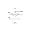
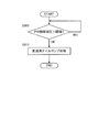
- FIG. 3 is a flowchart showing a control routine of the first embodiment.
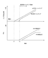
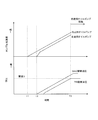
- FIG. 4 is a timing chart when the control routine of FIG. 3 is executed.
- FIG. 5 is a timing chart when a modification of the control routine of FIG. 3 is executed.
- FIG. 6 is a flowchart showing a control routine of the second embodiment.
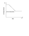
- FIG. 7 is a correction amount table for the SEC side hydraulic pressure command value.
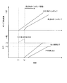
- FIG. 8 is a timing chart when the control routine of FIG. 6 is executed.
- FIG. 9 is a table used to calculate the SEC side hydraulic pressure command value.
- FIG. 10 is a flowchart showing a control routine of the third embodiment.
- FIG. 11 is a timing chart when the control routine of FIG. 10 is executed.
- FIG. 12 is a timing chart in the case of correcting the SEC side hydraulic pressure command value in the third embodiment.
- FIG. 1 is a schematic configuration diagram of a vehicle.
- the vehicle includes an engine 1, a torque converter 2 with a lock-up clutch 2 a, a forward / reverse switching mechanism 3, a variator 4, a final reduction mechanism 5, drive wheels 6, and a hydraulic circuit 100.
- Engine 1 constitutes a drive source for the vehicle.
- the output of the engine 1 is transmitted to the drive wheels 6 via the torque converter 2, the forward / reverse switching mechanism 3, the variator 4, and the final reduction mechanism 5.
- the variator 4 is provided in a power transmission path for transmitting power from the engine 1 to the drive wheels 6 together with the torque converter 2, the forward / reverse switching mechanism 3, and the final reduction mechanism 5.
- the forward / reverse switching mechanism 3 is provided between the torque converter 2 and the variator 4 in the power transmission path described above.
- the forward / reverse switching mechanism 3 switches the rotation direction of the input rotation between a forward rotation direction corresponding to forward travel and a reverse rotation direction corresponding to reverse travel.
- the forward / reverse switching mechanism 3 includes a forward clutch 31 and a reverse brake 32.
- the forward clutch 31 is fastened when the rotation direction is the forward rotation direction.
- the reverse brake 32 is fastened when the rotation direction is the reverse rotation direction.
- One of the forward clutch 31 and the reverse brake 32 can be configured as a clutch that intermittently rotates between the engine 1 and the variator 4.
- the variator 4 includes a primary pulley 41, a secondary pulley 42, and a belt 43 wound around the primary pulley 41 and the secondary pulley 42.
- the primary is also referred to as PRI
- the secondary is also referred to as SEC.
- the variator 4 changes the belt width of the belt 43 by changing the groove width between the PRI pulley 41 and the SEC pulley 42 (hereinafter, also simply referred to as “winding diameter”) to change the belt type continuously variable transmission.
- the mechanism is configured.
- the PRI pulley 41 includes a fixed pulley 41a and a movable pulley 41b.
- the controller 10 controls the amount of oil supplied to the PRI pulley hydraulic chamber 41c, the movable pulley 41b is operated and the groove width of the PRI pulley 41 is changed.
- the SEC pulley 42 includes a fixed pulley 42a and a movable pulley 42b.
- the controller 10 controls the SEC pressure, which is the pulley pressure supplied to the SEC pulley hydraulic chamber 42c, the movable pulley 42b is operated, and the groove width of the SEC pulley 42 is changed.
- the pulley pressure supplied to the PRI pulley hydraulic chamber 41c is referred to as PRI pressure.
- the belt 43 has a V-shaped sheave surface formed by the fixed pulley 41a and the movable pulley 41b of the PRI pulley 41, and a V-shape formed by the fixed pulley 42a and the movable pulley 42b of the SEC pulley 42. Wound around the sheave surface.
- the final deceleration mechanism 5 transmits the output rotation from the variator 4 to the drive wheels 6.
- the final reduction mechanism 5 includes a plurality of gear trains and differential gears. The final reduction mechanism 5 rotates the drive wheels 6 via the axle.
- the hydraulic circuit 100 supplies hydraulic pressure to the variator 4, specifically, the PRI pulley 41 and the SEC pulley 42.
- the hydraulic circuit 100 supplies hydraulic pressure to the forward / reverse switching mechanism 3, the lockup clutch 2a, and a lubrication system and a cooling system (not shown).
- the hydraulic circuit 100 is configured as follows.
- FIG. 2 is a schematic configuration diagram of the hydraulic circuit 100.
- the hydraulic circuit 100 includes an original pressure oil pump 101, a line pressure adjusting valve 102, a pressure reducing valve 103, a line pressure solenoid valve 104, a forward / reverse switching mechanism solenoid valve 105, a transmission circuit pressure solenoid valve 107, a manual A valve 108, a line pressure oil passage 109, a low pressure system control valve 130, a speed change circuit 110, and a line pressure electric oil pump 111 are provided.
- the solenoid valve is referred to as SOL.
- the original pressure oil pump 101 is a mechanical oil pump that is driven by the power of the engine 1.
- the original pressure oil pump 101 is connected to a line pressure adjusting valve 102, a pressure reducing valve 103, a transmission circuit pressure SOL 107 and a transmission circuit 110 via a line pressure oil passage 109.
- the line pressure oil passage 109 constitutes a line pressure oil passage.
- the line pressure is a hydraulic pressure that is a source pressure of the PRI pressure or the SEC pressure.
- the line pressure electric oil pump 111 is driven by an electric motor 117.
- the line pressure electric oil pump 111 is operated to supply line pressure when the engine 1 is stopped by, for example, idling / stop control and the main pressure oil pump 101 is stopped accordingly.
- the line pressure adjusting valve 102 adjusts the hydraulic pressure generated by the oil pump 101 to generate line pressure.
- the generation of the line pressure by the oil pump 101 includes the generation of the line pressure under the action of the line pressure regulating valve 102 as described above. Oil that is relieved when the line pressure regulating valve 102 regulates pressure is supplied to the lock-up clutch 2a, the lubrication system, and the cooling system via the low-pressure control valve 130.
- the pressure reducing valve 103 reduces the line pressure.
- the hydraulic pressure reduced by the pressure reducing valve 103 is supplied to the line pressure SOL 104 and the forward / reverse switching mechanism SOL 105.
- the line pressure SOL104 is a linear solenoid valve and generates a control hydraulic pressure corresponding to the control current.
- the control hydraulic pressure generated by the line pressure SOL104 is supplied to the line pressure adjustment valve 102, and the line pressure adjustment valve 102 adjusts the pressure by operating according to the control hydraulic pressure generated by the line pressure SOL104. For this reason, the command value of the line pressure PL can be set by the control current to the line pressure SOL104.
- the forward / reverse switching mechanism SOL 105 is a linear solenoid valve that generates hydraulic pressure in accordance with the control current.
- the hydraulic pressure generated by the forward / reverse switching mechanism SOL 105 is supplied to the forward clutch 31 and the reverse brake 32 via a manual valve 108 that operates according to the operation of the driver.
- the transmission circuit pressure SOL107 is a linear solenoid valve, and generates hydraulic pressure to be supplied to the transmission circuit 110 according to the control current. Therefore, the command value for the transmission circuit pressure can be set by the control current to the transmission circuit pressure SOL107.
- the transmission circuit pressure generated by the transmission circuit pressure SOL107 is supplied to the transmission oil passage 106.
- the transmission circuit pressure may be generated by, for example, a SOL that generates a control hydraulic pressure corresponding to the control current and a pressure regulating valve that generates a control circuit pressure from the line pressure PL according to the control hydraulic pressure generated by the SOL.
- the speed change circuit 110 includes a speed change oil path 106 connected to the line pressure oil path 109 via a speed change circuit pressure SOL107, and a speed change oil pump 112 interposed in the speed change oil path 106.
- the speed change oil passage 106 communicates the PRI pulley hydraulic chamber 41c and the SEC pulley hydraulic chamber 42c.
- the shift oil pump 112 is an electric oil pump that is driven by an electric motor 113.
- the electric motor 113 is controlled by the controller 10 via the inverter 114.
- the shift oil pump 112 can switch the rotation direction between the forward direction and the reverse direction.
- the forward direction is the direction in which oil is sent from the SEC pulley hydraulic chamber 42c side to the PRI pulley hydraulic chamber 41c side
- the reverse direction is the oil from the PRI pulley hydraulic chamber 41c side to the SEC pulley hydraulic chamber 42c side. It is the direction to send.
- the oil is supplied from the line pressure oil passage 109 to the transmission oil passage 106 so that the SEC-side hydraulic pressure is also not lower than the transmission circuit pressure command value.
- the command value of the transmission circuit pressure is set in consideration of preventing the belt 43 from slipping.
- the hydraulic pressure of the transmission oil passage 106 closer to the PRI pulley hydraulic chamber 41 c (hereinafter also referred to as “PRI side”) than the transmission oil pump 112 is also referred to as PRI-side hydraulic pressure.
- the shifting oil pump 112 controls shifting of oil in and out of the PRI pulley hydraulic chamber 41c.
- the outline of the shift control will be described later.
- the vehicle further includes a controller 10.
- the controller 10 is an electronic control device, and a signal from the sensor / switch group 11 is input to the controller 10.
- the controller 10 includes a microcomputer that includes a central processing unit (CPU), a read-only memory (ROM), a random access memory (RAM), and an input / output interface (I / O interface). It is also possible to configure the controller 10 with a plurality of microcomputers.
- the sensor switch group 11 detects, for example, an accelerator opening sensor that detects the accelerator opening of the vehicle, a brake sensor that detects the brake depression force of the vehicle, a vehicle speed sensor that detects the vehicle speed Vsp, and the rotational speed NE of the engine 1.
- An engine speed sensor detects, for example, an accelerator opening sensor that detects the accelerator opening of the vehicle, a brake sensor that detects the brake depression force of the vehicle, a vehicle speed sensor that detects the vehicle speed Vsp, and the rotational speed NE of the engine 1.
- the sensor switch group 11 further includes, for example, a PRI pressure sensor 115 that detects the PRI pressure, a SEC pressure sensor 116 that detects the SEC pressure, a PRI rotation speed sensor 120 that detects the input side rotation speed of the PRI pulley 41, and a SEC pulley 42. It includes a SEC rotation speed sensor 121 that detects the output side rotation speed, a pump rotation speed sensor 118 that detects the rotation speed of the shifting oil pump 112, and an oil temperature sensor 119 that detects the temperature of the oil.
- a signal from the sensor / switch group 11 may be input to the controller 10 via another controller, for example. The same applies to signals such as information generated by other controllers based on signals from the sensor / switch group 11.
- the controller 10 controls the hydraulic circuit 100 based on signals from the sensor / switch group 11. Specifically, the controller 10 controls the line pressure SOL 104 and the shift circuit 110 shown in FIG. The controller 10 is further configured to control the forward / reverse switching mechanism SOL 105 and the transmission circuit pressure SOL 107.
- the controller 10 In controlling the line pressure SOL104, the controller 10 energizes the line pressure SOL104 with a control current corresponding to the command value of the line pressure PL.
- the controller 10 sets a target gear ratio based on a signal from the sensor / switch group 11.
- the winding diameter (target winding diameter) of each of the pulleys 41 and 42 for realizing the target gear ratio is determined.
- the groove widths (target groove widths) of the pulleys 41 and 42 for realizing the target winding diameter are determined.
- the movable pulley 41b of the PRI pulley 41 moves in response to the oil being taken in and out from the PRI pulley hydraulic chamber 41c by the speed change oil pump, and the movable pulley 42b of the SEC pulley 42 is also moved accordingly. To do. That is, there is a correlation between the amount of movement of the movable pulley 41b of the PRI pulley 41 and the amount of movement of the movable pulley 42b of the SEC pulley 42.
- the controller 10 operates the shift oil pump 112 so that the position of the movable pulley 41b of the PRI pulley 41 becomes a position corresponding to the target gear ratio. Whether or not the movable pulley 41b is at a desired position is calculated by calculating the actual gear ratio from the detection values of the PRI rotational speed sensor 120 and the SEC rotational speed sensor 121, and whether the actual gear ratio matches the target gear ratio. Judgment by whether or not.
- the operation of the speed change oil pump 112 by the controller 10 is not limited to the speed change. Even when the target speed ratio does not change, the controller 10 operates the speed change oil pump 112 when oil leaks from the pulley hydraulic chambers 41c and 42c and the actual speed ratio changes. In the present embodiment, control for maintaining such a target gear ratio is also included in the shift control.
- the shift control of the present embodiment is feedback control for converging the position of the movable pulley 41b of the PRI pulley 41 to the target position.
- the control target of the feedback control is not the hydraulic pressure of each of the pulley hydraulic chambers 41c and 42c but the groove width of the PRI pulley 41, in other words, the position of the movable pulley 41b.
- a sensor that detects the position of the movable pulley 41b may be provided to determine whether or not the movable pulley 41b is at a position corresponding to the target gear ratio.
- the source pressure oil pump 101 and the line pressure electric oil pump 111 both stop, so that no oil pressure is supplied to the line pressure oil passage 109 and the SEC pulley hydraulic chamber 42c. For this reason, for example, when a long time has elapsed since the end of the operation of the vehicle, a so-called oil spilling state in which oil has dropped from the oil passage of the hydraulic circuit may occur. If the shift control is started immediately when the engine 1 is started in this oil drop state, the shift oil pump 112 is operated in a state where the line pressure oil passage 109 and the shift oil passage 106 are not filled with oil. become.
- the shifting oil pump 112 performs so-called idle driving, and the above-described abnormal noise is generated due to the air biting.
- the shifting oil pump 112 is operated in a state where oil has dropped, the bearing portion may be insufficiently lubricated, and the shifting oil pump 112 may be deteriorated.
- the controller 10 executes the control described below in order to suppress the adverse effects of starting the shift control in the oil drop state.
- FIG. 3 is a flowchart showing a control routine of the hydraulic circuit 100 executed by the controller 10 when the engine is started.
- the control routine is executed when the engine 1 is started.
- step S100 the controller 10 determines whether or not the oil in the speed change oil passage 106 is filled with a method described later.
- the controller 10 repeats the determination in step S100 until the SEC-side shifting oil passage 106 is filled with oil, and when it is filled, starts the shifting oil pump 112 in step S110. That is, in step S100, the controller 10 limits the operation of the transmission oil pump 112 by not permitting the operation of the transmission oil pump 112 until the SEC-side transmission oil passage 106 is filled with oil. .
- step S100 Specific examples of the determination method in step S100 include the following two.
- Threshold value 1 is set to a value that can be recognized that the gear shift oil pump 112 is clearly rotating, for example, several [rpm]. Theoretically, since it is only necessary to detect that the rotating shaft of the transmission oil pump 112 has started to rotate, a smaller value may be set. The axis of rotation may move. Therefore, the above-described threshold value 1 is set in order to prevent erroneous determination due to detection of such movement caused by vehicle body vibration or the like.
- FIG. 4 is a timing chart when the determination of the first example is performed.
- the SEC-side hydraulic pressure (SEC-side actual hydraulic pressure) starts to rise.
- the shifting oil pump 112 starts to rotate.
- the controller 10 operates the electric motor 113 in order to operate the transmission oil pump 112.
- the SEC-side actual hydraulic pressure and the PRI-side actual hydraulic pressure increase as the rotation of the main pressure oil pump 101 and the speed change oil pump 112 increases.
- Threshold value 2 is set to a value at which it can be recognized that the actual SEC-side hydraulic pressure has risen. Similarly to the threshold value 1, the threshold value 2 is set to a size having a margin in order to prevent erroneous determination.
- FIG. 5 is a timing chart when the determination of the second example is performed.
- the shifting oil pump 112 does not rotate in a state where oil has dropped, and it is possible to suppress the occurrence of abnormal noise due to air biting and the deterioration of the shifting oil pump 112 due to rotation in a non-lubricated state. .
- the operation of the transmission oil pump 112 is permitted. That is, it is determined based on the rotational speed of the shifting oil pump 112 whether or not the shifting oil path 106 on the SEC pulley hydraulic chamber 42c side of the shifting oil pump 112 is filled with oil. Thereby, even if the hydraulic circuit 100 does not include the SEC pressure sensor 116, it is possible to make an appropriate determination.
- This embodiment is the same as the first embodiment in that the operation of the speed change oil pump 112 is limited until oil is filled in the speed change oil passage 106 on the SEC side. However, it differs from the first embodiment in that the SEC-side hydraulic command value is corrected while the operation of the shifting oil pump 112 is limited. Hereinafter, this difference will be mainly described.
- the controller 10 sets a target gear ratio based on a signal from the sensor / switch group 11, and sets a SEC-side hydraulic command value corresponding to the target gear ratio.
- the SEC side oil pressure command value increases, the amount of oil flowing into the speed change oil passage 106 via the speed change circuit pressure solenoid valve 107 increases, and the time until oil is filled in the SEC side speed change oil passage 106 is increased. Shorter. Therefore, in the present embodiment, the time for limiting the operation of the speed change oil pump 112 is shortened by making the SEC side oil pressure command value larger than the value set according to the target speed ratio.
- FIG. 6 is a flowchart showing a control routine of the hydraulic circuit 100 executed by the controller 10 in this embodiment.
- step S200 the controller 10 calculates a basic SEC side hydraulic pressure command value.
- the basic SEC side hydraulic pressure command value is a SEC side hydraulic pressure command value corresponding to the target gear ratio.
- step S210 the controller 10 determines whether or not the SEC side oil passage 106 is filled with oil.
- the contents and method of determination are the same as in step S100 of FIG.
- the controller 10 executes the process of step S210 when the SEC-side shifting oil passage 106 is filled with oil, and executes the process of step S220 when the oil is not filled.
- step S220 the controller 10 corrects the basic SEC side hydraulic pressure command value to be large, and sets the corrected value as the SEC side hydraulic pressure command value.
- a table in which a larger correction amount is set as the oil temperature is lower as shown in FIG. 7 is created in advance and stored in the controller 10, and the controller 10 determines the correction amount determined based on the table. Add to the basic SEC hydraulic pressure command value.
- step S230 the SEC-side hydraulic command value calculated in step S200 is the basic SEC-side hydraulic command value.
- the controller 10 starts the shift oil pump 112 in step S240.
- FIG. 8 is a timing chart when the above-described control is executed.
- the movements of the source pressure oil pump 101 and the transmission oil pump 112 and the changes in the SEC side actual hydraulic pressure and the PRI side actual hydraulic pressure are all the same as in FIG.
- P1 is a basic SEC side hydraulic pressure command value
- P2 is a PRI side hydraulic pressure command value.
- the SEC-side hydraulic command value is from the timing T1 at which the source pressure oil pump 101 starts to the timing T2 at which the SEC-side transmission oil passage 106 is filled with oil. It gradually increases by repeating the correction. As a result, the interval from the timing T1 to the timing T2 becomes shorter than when the basic SEC side hydraulic pressure command value is not corrected for increase.
- the SEC side hydraulic pressure command value returns to the basic SEC side hydraulic pressure command value at timing T2.
- step S220 in FIG. 6 the SEC-side hydraulic command value from timing T1 to timing T2 is set by correcting the basic SEC-side hydraulic command value.
- the present invention is not limited to this.
- a table in which the SEC side oil pressure command value corresponding to the oil temperature is set is created and stored in the controller 10, and the controller 10 directly inputs the SEC side oil pressure command value from the table. You may make it calculate.
- the SEC side hydraulic pressure command value gradually increases from the timing T1 to the timing T2 has been described.
- the present invention is not limited to this. For example, at the timing T1, the SEC-side hydraulic pressure command value at the timing T2 in FIG. 8 may be set and maintained until the timing T2.
- the target hydraulic pressure of the shift oil passage 106 on the SEC pulley hydraulic chamber 42c side of the shift oil pump 112 is changed to the gear for shift. It is set higher than when the operation of the oil pump 112 is not restricted. As a result, the rate of increase of the SEC pressure is increased, so that the time during which the operation of the shift oil pump 112 is restricted is shortened compared to the case where the target oil pressure is not increased. As a result, it is possible to shorten the time required for shifting to a shiftable state as compared with the case where the target hydraulic pressure is not increased.
- the target oil pressure while the operation of the shifting oil pump 112 is restricted is set higher as the oil temperature is lower.
- the friction of the pumps 101 and 112 increases as the temperature decreases, according to the present embodiment, the source pressure increases as the friction increases, so the target hydraulic pressure is not increased for the time required for shifting. It can be made shorter than the case.
- the operation of the speed change oil pump 112 is limited until oil is filled in the speed change oil passage 106 on the SEC side.
- the transmission oil pump 112 is operated until the hydraulic pressure in the PRI-side transmission oil passage 106 reaches a predetermined pressure. Limit.
- FIG. 10 is a flowchart showing the control routine of the present embodiment described above.
- step S300 the controller 10 determines whether or not the actual oil pressure of the PRI-side transmission oil passage 106 has become higher than the threshold value 3.
- the threshold 3 is a PRI pressure determined based on the target gear ratio.
- the controller 10 starts the shift oil pump 112 in step S310.
- FIG. 11 is a timing chart when the control routine of FIG. 10 is executed.
- the transmission oil pump 112 starts to rotate due to the differential pressure between the SEC side and the PRI side. Since the transmission oil pump 112 rotates due to the above-described differential pressure, if the SEC-side actual hydraulic pressure continues to increase, the rotational speed of the transmission oil pump 112 also increases.
- the PRI-side actual hydraulic pressure reaches the PRI pressure (threshold 3) determined based on the target gear ratio at timing T3, the controller 10 starts the transmission oil pump 112.
- the speed change is performed until the PRI pressure is increased to the pressure determined based on the target speed ratio.
- the power consumed by the oil pump 112 can be reduced. That is, the power consumption of the shifting oil pump 112 can be reduced as compared with the first and second embodiments.
- the SEC-side command hydraulic pressure may be corrected in the same manner as in the second embodiment. In this case, as shown in FIG. 12, the correction of the SEC-side command hydraulic pressure is continued until timing T3.
- the PRI pulley hydraulic chamber 41c side relative to the transmission oil pump 112 is present.
- the operation of the shifting oil pump 112 is limited until the actual hydraulic pressure in the shifting oil passage 106 reaches the command hydraulic pressure. Thereby, it is possible to reduce the power consumed by the speed change oil pump 112 until the PRI pressure is increased to a pressure determined based on the target speed ratio.
Landscapes
- Engineering & Computer Science (AREA)
- General Engineering & Computer Science (AREA)
- Mechanical Engineering (AREA)
- Control Of Transmission Device (AREA)
Abstract
元圧用オイルポンプによりセカンダリプーリ油室に油圧を供給し、プライマリプーリ油室とセカンダリプーリ油室との間の油路に配置された電動オイルポンプによりプライマリプーリ油室のオイルの出入りを制御する無段変速機の制御方法において、元圧用オイルポンプの始動後は、電動オイルポンプよりもセカンダリ油室側の油路にオイルが充填されるまで、電動オイルポンプの稼働を制限する。
Description
本発明は、無段変速機の制御に関する。
無段変速機の油圧回路として、オイルパンからオイルを汲み上げて変速用の元圧となるライン圧を発生させる元圧用のオイルポンプと、変速用の電動オイルポンプと、を備えるものがJP2008-240894A1に開示されている。上記文献に記載の油圧回路では、プライマリプーリ油室とセカンダリプーリ油室とを連通し、かつライン圧となる油路と接続される変速用油路に電動オイルポンプが介装されている。そして、上記文献に記載の油圧回路においては、電動オイルポンプによってプライマリプーリ油室のオイルの出入りを調整することで、変速制御を行う。
ところで、上記文献に記載の油圧回路を備える無段変速機では、変速制御を行うためには変速用油路にオイルが充填されていることが必要となる。このため、油圧回路が、オイルが抜け落ちたいわゆる油落ちした状態にあるときに、エンジンが始動されて変速制御を開始すると、変速用油路にオイルが充填されるまでは電動オイルポンプがいわゆるエア噛みを起こし、異音が発生する。
しかしながら、上記文献には油落ちした状態でエンジンが始動された場合における制御について記載されていない。
そこで本発明では、上述したエア噛みによる異音発生のような、油落ちした状態で変速制御を開始することによる弊害を抑制し得る制御方法を提供することを目的とする。
本発明のある態様によれば、元圧用オイルポンプによりセカンダリプーリ油室に油圧を供給し、プライマリプーリ油室とセカンダリプーリ油室との間の油路に配置された電動オイルポンプによりプライマリプーリ油室のオイルの出入りを制御する制御方法が提供される。この油圧制御方法においては、元圧用オイルポンプを始動した後、電動オイルポンプよりもセカンダリ油室側の油路にオイルが充填されるまで、電動オイルポンプの稼働が制限される。
以下、添付図面を参照しながら本発明の実施形態について説明する。
(第1実施形態)
図1は、車両の概略構成図である。車両は、エンジン1と、ロックアップクラッチ2a付きトルクコンバータ2と、前後進切替機構3と、バリエータ4と、終減速機構5と、駆動輪6と、油圧回路100と、を備える。
図1は、車両の概略構成図である。車両は、エンジン1と、ロックアップクラッチ2a付きトルクコンバータ2と、前後進切替機構3と、バリエータ4と、終減速機構5と、駆動輪6と、油圧回路100と、を備える。
エンジン1は、車両の駆動源を構成する。エンジン1の出力は、トルクコンバータ2、前後進切替機構3、バリエータ4、及び終減速機構5を介して駆動輪6へと伝達される。したがって、バリエータ4は、トルクコンバータ2や前後進切替機構3や終減速機構5とともに、エンジン1から駆動輪6に動力を伝達する動力伝達経路に設けられる。
前後進切替機構3は、上述の動力伝達経路においてトルクコンバータ2とバリエータ4との間に設けられる。前後進切替機構3は、前進走行に対応する正転方向と後退走行に対応する逆転方向との間で、入力される回転の回転方向を切り替える。
前後進切替機構3は具体的には、前進クラッチ31と、後退ブレーキ32と、を備える。前進クラッチ31は、回転方向を正転方向とする場合に締結される。後退ブレーキ32は、回転方向を逆転方向とする場合に締結される。前進クラッチ31及び後退ブレーキ32の一方は、エンジン1とバリエータ4と間の回転を断続するクラッチとして構成することができる。
バリエータ4は、プライマリプーリ41と、セカンダリプーリ42と、プライマリプーリ41及びセカンダリプーリ42に巻き掛けられたベルト43と、を有する。以下では、プライマリをPRIとも称し、セカンダリをSECとも称す。バリエータ4は、PRIプーリ41とSECプーリ42との溝幅を変更することでベルト43の巻掛け径(以下、単に「巻掛け径」ともいう)を変更し、変速を行うベルト式無段変速機構を構成している。
PRIプーリ41は、固定プーリ41aと、可動プーリ41bと、を備える。コントローラ10がPRIプーリ油圧室41cに供給されるオイル量を制御することにより、可動プーリ41bが作動し、PRIプーリ41の溝幅が変更される。
SECプーリ42は、固定プーリ42aと、可動プーリ42bと、を備える。コントローラ10がSECプーリ油圧室42cに供給されるプーリ圧であるSEC圧を制御することにより、可動プーリ42bが作動し、SECプーリ42の溝幅が変更される。なお、PRIプーリ油圧室41cに供給されるプーリ圧を、PRI圧とする。
ベルト43は、PRIプーリ41の固定プーリ41aと可動プーリ41bとにより形成されるV字形状をなすシーブ面と、SECプーリ42の固定プーリ42aと可動プーリ42bとにより形成されるV字形状をなすシーブ面に巻き掛けられる。
終減速機構5は、バリエータ4からの出力回転を駆動輪6に伝達する。終減速機構5は、複数の歯車列やディファレンシャルギアを有して構成される。終減速機構5は、車軸を介して駆動輪6を回転する。
油圧回路100は、バリエータ4、具体的にはPRIプーリ41及びSECプーリ42に油圧を供給する。油圧回路100は、前後進切替機構3やロックアップクラッチ2a、及び図示しない潤滑系や冷却系にも油圧を供給する。油圧回路100は具体的には、次のように構成される。
図2は、油圧回路100の概略構成図である。油圧回路100は、元圧用オイルポンプ101と、ライン圧調整弁102と、減圧弁103と、ライン圧ソレノイドバルブ104と、前後進切替機構用ソレノイドバルブ105と、変速回路圧ソレノイドバルブ107と、マニュアルバルブ108と、ライン圧油路109と、低圧系制御弁130と、変速用回路110と、ライン圧用電動オイルポンプ111と、を備える。以下では、ソレノイドバルブをSOLと称す。
元圧用オイルポンプ101は、エンジン1の動力によって駆動する機械式のオイルポンプである。元圧用オイルポンプ101は、ライン圧油路109を介して、ライン圧調整弁102と、減圧弁103と、変速回路圧SOL107及び変速用回路110と、に接続される。ライン圧油路109はライン圧の油路を構成する。ライン圧は、PRI圧やSEC圧の元圧となる油圧である。
ライン圧用電動オイルポンプ111は、電動モータ117によって駆動する。ライン圧用電動オイルポンプ111は、例えばアイドリング・ストップ制御によりエンジン1が停止し、これに伴い元圧用オイルポンプ101が停止した場合に、ライン圧を供給するために稼働する。
ライン圧調整弁102は、オイルポンプ101が発生させる油圧を調整してライン圧を生成する。オイルポンプ101がライン圧を発生させることは、このようなライン圧調整弁102の作用のもと、ライン圧を発生させることを含む。ライン圧調整弁102が調圧時にリリーフするオイルは、低圧系制御弁130を介してロックアップクラッチ2a、潤滑系、冷却系に供給される。
減圧弁103は、ライン圧を減圧する。減圧弁103によって減圧された油圧は、ライン圧SOL104や前後進切替機構用SOL105に供給される。
ライン圧SOL104は、リニアソレノイドバルブであり、制御電流に応じた制御油圧を生成する。ライン圧SOL104が生成した制御油圧は、ライン圧調整弁102に供給され、ライン圧調整弁102は、ライン圧SOL104が生成した制御油圧に応じて作動することで調圧を行う。このため、ライン圧SOL104への制御電流によってライン圧PLの指令値を設定することができる。
前後進切替機構用SOL105は、リニアソレノイドバルブであり、制御電流に応じた油圧を生成する。前後進切替機構用SOL105が生成した油圧は、運転者の操作に応じて作動するマニュアルバルブ108を介して前進クラッチ31や後退ブレーキ32に供給される。
変速回路圧SOL107は、リニアソレノイドバルブであり、制御電流に応じて変速用回路110に供給する油圧を生成する。このため、変速回路圧SOL107への制御電流によって変速回路圧の指令値を設定することができる。変速回路圧SOL107が生成した変速回路圧は変速用油路106に供給される。変速回路圧は例えば、制御電流に応じた制御油圧を生成するSOLと、当該SOLが生成した制御油圧に応じてライン圧PLから制御回路圧を生成する調圧弁とによって生成されてもよい。
変速用回路110は、変速回路圧SOL107を介してライン圧油路109と接続される変速用油路106と、変速用油路106に介装される変速用オイルポンプ112と、を備える。変速用油路106はPRIプーリ油圧室41cとSECプーリ油圧室42cとを連通する。
変速用オイルポンプ112は、電動モータ113によって駆動する電動式のオイルポンプである。電動モータ113はインバータ114を介してコントローラ10に制御される。変速用オイルポンプ112は、回転方向を正方向と逆方向に切り替え可能である。ここでいう正方向とは、オイルをSECプーリ油圧室42c側からPRIプーリ油圧室41c側へ送る方向であり、逆方向とは、オイルをPRIプーリ油圧室41c側からSECプーリ油圧室42c側へ送る方向である。
変速用オイルポンプ112が正方向に回転すると、変速用油路106及びSECプーリ油圧室42cにあるオイルがPRIプーリ油圧室41cに供給される。これによりPRIプーリ41の可動プーリ41bが固定プーリ41aに近づく方向に移動し、PRIプーリ41の溝幅が減少する。一方、SECプーリ42の可動プーリ42bは固定プーリ42aから遠ざかる方向に移動し、SECプーリ42の溝幅が増大する。なお、変速用オイルポンプ112が正回転する際には、変速用オイルポンプ112よりもSECプーリ油圧室42c側(以下、「SEC側」とも称する)の変速用油路106の油圧(以下、「SEC側油圧」とも称する)が変速回路圧の指令値を下回らないように、ライン圧油路109から変速用油路106へオイルが供給される。変速回路圧の指令値は、ベルト43の滑りを防止すること等を考慮して設定される。なお、変速用オイルポンプ112よりもPRIプーリ油圧室41c側(以下、「PRI側」とも称する)の変速用油路106の油圧を、PRI側油圧とも称する。
また、変速用オイルポンプ112が逆方向に回転すると、PRIプーリ油圧室41cからオイルが流出する。これによりPRIプーリ41の可動プーリ41bが固定プーリ41aから離れる方向に移動し、PRIプーリ41の溝幅が増大する。一方、SECプーリ42の可動プーリ42bは固定プーリ42aに近づく方向に移動し、SECプーリ42の溝幅が減少する。PRIプーリ油圧室41cから流出したオイルが流入することでSEC側油圧は上昇するが、変速回路圧SOL107によりSEC側油圧が指令値を超えないように制御される。すなわち、SEC側油圧が指令値を超える場合には、変速回路圧SOL107を介して変速用油路106からオイルが排出される。一方、SEC側油圧が指令値未満の場合には、変速回路圧SOL107を介してライン圧油路109からオイルが流入する。
上記の通り、本実施形態の無段変速機では、変速用オイルポンプ112によりPRIプーリ油圧室41cのオイルの出入りを制御することによって変速を行う。変速制御の概要については後述する。
図1に戻り、車両はコントローラ10をさらに備える。コントローラ10は電子制御装置であり、コントローラ10には、センサ・スイッチ群11からの信号が入力される。なお、コントローラ10は、中央演算装置(CPU)、読み出し専用メモリ(ROM)、ランダムアクセスメモリ(RAM)及び入出力インタフェース(I/Oインタフェース)を備えたマイクロコンピュータで構成される。コントローラ10を複数のマイクロコンピュータで構成することも可能である。
センサ・スイッチ群11は例えば、車両のアクセル開度を検出するアクセル開度センサや、車両のブレーキ踏力を検出するブレーキセンサや、車速Vspを検出する車速センサや、エンジン1の回転速度NEを検出するエンジン回転速度センサを含む。
センサ・スイッチ群11はさらに例えば、PRI圧を検出するPRI圧センサ115、SEC圧を検出するSEC圧センサ116、PRIプーリ41の入力側回転速度を検出するPRI回転速度センサ120、SECプーリ42の出力側回転速度を検出するSEC回転速度センサ121、変速用オイルポンプ112の回転速度を検出するポンプ回転速度センサ118、及びオイルの温度を検出する油温センサ119を含む。センサ・スイッチ群11からの信号は例えば、他のコントローラを介してコントローラ10に入力されてもよい。センサ・スイッチ群11からの信号に基づき他のコントローラで生成された情報等の信号についても同様である。
コントローラ10は、センサ・スイッチ群11からの信号に基づき油圧回路100を制御する。具体的には、コントローラ10は、図2に示すライン圧SOL104や変速用回路110を制御する。コントローラ10はさらに、前後進切替機構用SOL105や変速回路圧SOL107を制御するように構成される。
ライン圧SOL104を制御するにあたり、コントローラ10は、ライン圧PLの指令値に応じた制御電流をライン圧SOL104に通電する。
変速制御を実行するにあたり、コントローラ10はセンサ・スイッチ群11からの信号に基づいて目標変速比を設定する。目標変速比が定まれば、当該目標変速比を実現するための各プーリ41、42の巻掛け径(目標巻掛け径)が定まる。目標巻掛け径が定まれば、目標巻掛け径を実現するための各プーリ41、42の溝幅(目標溝幅)が定まる。
また、変速用回路110では、変速用オイルポンプによるPRIプーリ油圧室41cからのオイルの出し入れに応じてPRIプーリ41の可動プーリ41bが移動し、これに応じてSECプーリ42の可動プーリ42bも移動する。つまり、PRIプーリ41の可動プーリ41bの移動量とSECプーリ42の可動プーリ42bの移動量とには相関がある。
そこでコントローラ10は、PRIプーリ41の可動プーリ41bの位置が目標変速比に応じた位置になるよう変速用オイルポンプ112を稼働させる。可動プーリ41bが所望の位置にあるか否かは、PRI回転速度センサ120及びSEC回転速度センサ121の検出値から実変速比を算出し、この実変速比と目標変速比とが一致しているか否かによって判断する。
また、コントローラ10が変速用オイルポンプ112を稼働させるのは、変速時に限られるわけではない。目標変速比が変化しない場合でも、各プーリ油圧室41c、42cからオイルがリークして実変速比が変化した場合には、コントローラ10は変速用オイルポンプ112を稼働させる。本実施形態においては、このような目標変速比を維持するための制御も、変速制御に含めることとする。
すなわち、本実施形態の変速制御は、PRIプーリ41の可動プーリ41bの位置を目標位置に収束させるフィードバック制御である。そして、当該フィードバック制御の制御対象は、各プーリ油圧室41c、42cの油圧ではなく、PRIプーリ41の溝幅、換言すると可動プーリ41bの位置である。
なお、可動プーリ41bの位置を検出するセンサを設けて、可動プーリ41bが目標変速比に応じた位置にあるか否かを判断してもよい。
ところで、いわゆるイグニッションOFFの状態では、元圧用オイルポンプ101及びライン圧用電動オイルポンプ111はいずれも停止するので、ライン圧油路109及びSECプーリ油圧室42cには油圧が供給されなくなる。このため、例えば車両の運転終了から長時間が経過した場合には、油圧回路の油路からオイルが抜け落ちた、いわゆる油落ち状態となることがある。この油落ち状態でエンジン1が始動されたときに、変速制御をただちに開始すると、ライン圧油路109及び変速用油路106にオイルが充填されていない状態で変速用オイルポンプ112を稼働させることになる。そうすると、変速用オイルポンプ112がいわゆる空打ちをすることになり、上述したエア噛みによる異音が発生する。また、油落ち状態で変速用オイルポンプ112を稼働させると、軸受け部の潤滑が不十分となって変速用オイルポンプ112の劣化を招くおそれもある。
そこで本実施形態では、油落ち状態で変速制御を開始することの弊害を抑制するために、コントローラ10は以下に説明する制御を実行する。
図3は、コントローラ10がエンジン始動時に実行する、油圧回路100の制御ルーチンを示すフローチャートである。当該制御ルーチンは、エンジン1が始動したときに実行される。
ステップS100で、コントローラ10はSEC側の変速用油路106にオイルが充填されているか否かを後述する方法により判定する。コントローラ10は、SEC側の変速用油路106にオイルが充填されるまでステップS100の判定を繰り返し、充填されたらステップS110で変速用オイルポンプ112を始動する。すなわち、ステップS100では、コントローラ10はSEC側の変速用油路106にオイルが充填されるまで、変速用オイルポンプ112の稼働を許可しないことにより、変速用オイルポンプ112の稼働を制限している。
ステップS100の判定方法の具体例としては、次の2つが挙げられる。
(第1例)
SEC側の変速用油路106にオイルが充填されれば、変速用オイルポンプ112は、電動モータ113で駆動しなくても、SEC側とPRI側との油圧差によって回転する。そこで、ポンプ回転速度センサ118により検出した変速用オイルポンプ112の回転速度が、所定の回転速度(閾値1)よりも高くなったら、コントローラ10はSEC側の変速用油路106にオイルが充填されたと判定する。
SEC側の変速用油路106にオイルが充填されれば、変速用オイルポンプ112は、電動モータ113で駆動しなくても、SEC側とPRI側との油圧差によって回転する。そこで、ポンプ回転速度センサ118により検出した変速用オイルポンプ112の回転速度が、所定の回転速度(閾値1)よりも高くなったら、コントローラ10はSEC側の変速用油路106にオイルが充填されたと判定する。
閾値1は、変速用オイルポンプ112が明らかに回転していると認識できる値、例えば数[rpm]に設定する。理論上は、変速用オイルポンプ112の回転軸が回転し始めたことが検知されればよいので、さらに小さい値を設定してもよいが、実際には、車両振動等によって変速用オイルポンプ112の回転軸が動くこともある。そこで、このような車体振動等による動きを検出することによる誤判定を防止するために、上述した大きさの閾値1を設定する。
図4は、第1例の判定を行った場合のタイミングチャートである。
タイミングT1において元圧用オイルポンプ101が稼働開始すると、やがてSEC側の油圧(SEC側実油圧)が上昇し始める。これに伴い変速用オイルポンプ112が回転し始める。そして、変速用オイルポンプ112の回転速度が閾値1を超えたタイミングT2において、コントローラ10が変速用オイルポンプ112を稼働させるために電動モータ113を稼働させる。その後は、元圧用オイルポンプ101及び変速用オイルポンプ112の回転上昇に伴って、SEC側実油圧及びPRI側実油圧は上昇する。
(第2例)
SEC側の変速用油路106にオイルが充填されれば、SEC側実油圧が上昇する。そこで、SEC圧センサ116でSEC側実油圧の上昇を検知したら、つまりSEC側実油圧が所定の油圧(閾値2)を超えたら、コントローラ10はSEC側の変速用油路106にオイルが充填されたと判定する。
SEC側の変速用油路106にオイルが充填されれば、SEC側実油圧が上昇する。そこで、SEC圧センサ116でSEC側実油圧の上昇を検知したら、つまりSEC側実油圧が所定の油圧(閾値2)を超えたら、コントローラ10はSEC側の変速用油路106にオイルが充填されたと判定する。
閾値2は、SEC側実油圧が明らかに上昇していると認識できる値に設定する。閾値2も閾値1と同様に誤判定を防止するために、余裕をもった大きさに設定する。
図5は、第2例の判定を行った場合のタイミングチャートである。
元圧用オイルポンプ101及び変速用オイルポンプ112の動きと、SEC側実油圧及びPRI側実油圧の変化は、いずれも図4と同様である。ただし、変速用オイルポンプ112の稼働開始を決定する根拠が、タイミングT2においてSEC側実油圧が閾値2より高くなったことである。
以上のように本実施形態では、元圧用オイルポンプ101が始動した後は、変速用オイルポンプ(電動オイルポンプ)112よりもSECプーリ油圧室42c側の変速用油路106にオイルが充填されるまで、変速用オイルポンプ112の稼働を制限する。これにより、油落ちした状態で変速用オイルポンプ112が回転することがなくなり、エア噛みによる異音の発生や、無潤滑状態で回転することによる変速用オイルポンプ112の劣化を抑制することができる。
本実施形態では、一例として、変速用オイルポンプ112の回転速度が所定回転速度に達したら、変速用オイルポンプ112の稼働を許可する。つまり、変速用オイルポンプ112よりもSECプーリ油圧室42c側の変速用油路106にオイルが充填されたか否かを、変速用オイルポンプ112の回転速度に基づいて判定する。これにより、仮に油圧回路100がSEC圧センサ116を備えない場合でも、適切な判定をすることが可能となる。
本実施形態では、他の例として、変速用オイルポンプ112よりもSECプーリ油圧室42c側の変速用油路106の油圧が所定油圧に達したら、変速用オイルポンプ112の稼働を許可する。つまり、変速用オイルポンプ112よりもSECプーリ油圧室42c側の変速用油路106にオイルが充填されたか否かを、当該油路の圧力に基づいて判定するので、正確な判定が可能となる。
(第2実施形態)
本実施形態は、SEC側の変速用油路106にオイルが充填されるまで変速用オイルポンプ112の稼働を制限する点は第1実施形態と同様である。ただし、変速用オイルポンプ112の稼働を制限している間に、SEC側油圧指令値を補正する点が第1実施形態と異なる。以下、この相違点を中心に説明する。
本実施形態は、SEC側の変速用油路106にオイルが充填されるまで変速用オイルポンプ112の稼働を制限する点は第1実施形態と同様である。ただし、変速用オイルポンプ112の稼働を制限している間に、SEC側油圧指令値を補正する点が第1実施形態と異なる。以下、この相違点を中心に説明する。
エンジン1が始動すると、コントローラ10は、センサ・スイッチ群11からの信号に基づいて目標変速比を設定し、目標変速比に応じたSEC側油圧指令値を設定する。SEC側油圧指令値が大きくなるほど、変速回路圧ソレノイドバルブ107を介して変速用油路106に流入するオイル量が多くなり、SEC側の変速用油路106にオイルが充填されるまでの時間が短くなる。そこで本実施形態では、SEC側油圧指令値を目標変速比に応じて設定される値よりも大きくすることにより、変速用オイルポンプ112の稼働を制限する時間を短縮する。
図6は、本実施形態でコントローラ10が実行する油圧回路100の制御ルーチンを示すフローチャートである。
ステップS200で、コントローラ10は、基本SEC側油圧指令値を算出する。基本SEC側油圧指令値は、目標変速比に応じたSEC側油圧指令値である。
ステップS210で、コントローラ10はSEC側の変速用油路106にオイルが充填されているか否かを判定する。判定の内容及び方法は図3のステップS100と同様である。コントローラ10は、SEC側の変速用油路106にオイルが充填されている場合にはステップS210の処理を実行し、充填されていない場合にはステップS220の処理を実行する。
ステップS220で、コントローラ10は、基本SEC側油圧指令値を大きくするよう補正し、補正後の値をSEC側油圧指令値とする。具体的には、例えば図7に示すような油温が低いほど大きな補正量を設定したテーブルを予め作成してコントローラ10に格納しておき、コントローラ10は当該テーブルに基づいて決定した補正量を基本SEC側油圧指令値に加算する。
コントローラ10は、上述したステップS220の処理をSEC側の変速用油路106にオイルが充填されるまで繰り返したら、ステップS230において、SEC側油圧指令値をステップS200で算出した基本SEC側油圧指令値に戻す。そして、コントローラ10はステップS240において変速用オイルポンプ112を始動する。
図8は、上述した制御を実行した場合のタイミングチャートである。元圧用オイルポンプ101及び変速用オイルポンプ112の動きと、SEC側実油圧及びPRI側実油圧の変化は、いずれも図4と同様である。図中のP1は基本SEC側油圧指令値、P2はPRI側油圧指令値である。
図8に示すように、元圧用オイルポンプ101が始動開始するタイミングT1から、SEC側の変速用油路106がオイルの充填された状態になるタイミングT2までの間は、SEC側油圧指令値は補正を繰り返すことによって徐々に増大する。これにより、タイミングT1からタイミングT2までの間隔は、基本SEC側油圧指令値を増大補正しない場合に比べて短くなる。
そして、SEC側油圧指令値は、タイミングT2で基本SEC側油圧指令値に戻る。
なお、図6のステップS220では基本SEC側油圧指令値を補正することによって、タイミングT1からタイミングT2までの間におけるSEC側油圧指令値を設定したが、これに限られるわけではない。例えば、図9に示すような、油温に応じたSEC側油圧指令値を設定したテーブルを作成してコントローラ10に格納しておき、コントローラ10が当該テーブルからSEC側油圧指令値を直接的に算出するようにしてもよい。また、上記説明では、タイミングT1からタイミングT2までSEC側油圧指令値が徐々に増加する場合を説明したが、これに限られるわけではない。例えば、タイミングT1の時点で、図8のタイミングT2におけるSEC側油圧指令値に設定し、これをタイミングT2まで維持するようにしてもよい。
以上のように本実施形態では、変速用オイルポンプ112の稼働を制限している間は、変速用オイルポンプ112よりもSECプーリ油圧室42c側の変速用油路106の目標油圧を、変速用オイルポンプ112の稼働を制限していない場合に比べて高く設定する。これにより、SEC圧の上昇速度が高まるので、変速用オイルポンプ112の稼働が制限される時間が、目標油圧を高めない場合に比べて短縮される。その結果、変速可能な状態になるまでに要する時間を、目標油圧を高めない場合に比べて短くすることができる。
本実施形態では、変速用オイルポンプ112の稼働を制限している間の目標油圧は、油温が低いほど高く設定する。低温時ほど各ポンプ101、112のフリクションは大きくなるが、本実施形態によればフリクションが増大するほど元圧が高くなるので、変速可能な状態になるまでに要する時間を、目標油圧を高めない場合に比べてより短くすることができる。
(第3実施形態)
第1実施形態及び第2実施形態では、SEC側の変速用油路106にオイルが充填されるまで変速用オイルポンプ112の稼働を制限する。これに対し本実施形態では、SEC側の変速用油路106にオイルが充填された後、さらにPRI側の変速用油路106の油圧が所定圧に到達するまで、変速用オイルポンプ112の稼働を制限する。
第1実施形態及び第2実施形態では、SEC側の変速用油路106にオイルが充填されるまで変速用オイルポンプ112の稼働を制限する。これに対し本実施形態では、SEC側の変速用油路106にオイルが充填された後、さらにPRI側の変速用油路106の油圧が所定圧に到達するまで、変速用オイルポンプ112の稼働を制限する。
図10は、上述した本実施形態の制御ルーチンを示すフローチャートである。
ステップS300で、コントローラ10はPRI側の変速用油路106の実油圧が閾値3より高くなったか否かを判定する。閾値3は、目標変速比に基づいて定まるPRI圧である。
そして、コントローラ10は、PRI側の変速用油路106の実油圧が閾値3より高くなったら、ステップS310で変速用オイルポンプ112を始動する。
図11は、図10の制御ルーチンを実行した場合のタイミングチャートである。
タイミングT1で元圧用オイルポンプ101が始動すると、その後のタイミングT2においてSEC側実油圧が上昇を開始する。そして、SEC側実油圧の上昇に伴い、SEC側とPRI側との差圧によって変速用オイルポンプ112が回転を始める。変速用オイルポンプ112は前述した差圧によって回転するので、SEC側実油圧が上昇し続ければ変速用オイルポンプ112の回転速度も上昇する。そして、タイミングT3においてPRI側実油圧が目標変速比に基づいて定まるPRI圧(閾値3)に到達したら、コントローラ10は変速用オイルポンプ112を始動する。
このように、PRI側実油圧が目標変速比に基づいて定まるPRI圧に到達するまで変速用オイルポンプ112の稼働を制限すると、PRI圧を目標変速比に基づいて定まる圧力に上昇させるまでに変速用オイルポンプ112が消費する電力を削減することができる。つまり、第1実施形態や第2実施形態に比べて、変速用オイルポンプ112の消費電力を低減することができる。
なお、本実施形態においても、第2実施形態と同様のSEC側指令油圧の補正を行ってもよい。この場合、図12に示すように、タイミングT3までSEC側指令油圧の補正が継続される。
以上のように本実施形態では、変速用オイルポンプ112よりもSECプーリ油圧室42c側の変速用油路106にオイルが充填された後も、変速用オイルポンプ112よりもPRIプーリ油圧室41c側の変速用油路106の実油圧が指令油圧に到達するまで、変速用オイルポンプ112の稼働を制限する。これにより、PRI圧を目標変速比に基づいて定まる圧力に上昇させるまでに変速用オイルポンプ112が消費する電力を削減することができる。
なお、上述した各実施形態では、元圧を供給するオイルポンプとして、機械式オイルポンプ(元圧用オイルポンプ101)と、電動オイルポンプ(ライン圧用電動オイルポンプ111)とを併せ持つ構成について説明したが、いずれか一方だけを備える構成であってもよい。
以上、本発明の実施形態について説明したが、上記実施形態は本発明の適用例の一部を示したに過ぎず、本発明の技術的範囲を上記実施形態の具体的構成に限定する趣旨ではない。
本願は2016年8月29日に日本国特許庁に出願された特願2016-166760に基づく優先権を主張し、この出願の全ての内容は参照により本明細書に組み込まれる。
Claims (7)
- 元圧用オイルポンプによりセカンダリプーリ油室に油圧を供給し、
プライマリプーリ油室と前記セカンダリプーリ油室との間の油路に配置された電動オイルポンプにより前記プライマリプーリ油室のオイルの出入りを制御する無段変速機の制御方法において、
前記元圧用オイルポンプの始動後は、前記電動オイルポンプよりも前記セカンダリプーリ油室側の前記油路にオイルが充填されるまで、前記電動オイルポンプの稼働を制限する無段変速機の制御方法。 - 請求項1に記載の無段変速機の制御方法において、
前記電動オイルポンプの回転速度が所定回転速度に達したら、前記電動オイルポンプの稼働を許可する無段変速機の制御方法。 - 請求項1に記載の無段変速機の制御方法において、
前記電動オイルポンプよりも前記セカンダリプーリ油室側の前記油路の油圧が所定油圧に達したら、前記電動オイルポンプの稼働を許可する無段変速機の制御方法。 - 請求項1に記載の無段変速機の制御方法において、
前記電動オイルポンプよりも前記セカンダリプーリ油室側の前記油路にオイルが充填された後も、前記電動オイルポンプよりも前記プライマリプーリ油室側の前記油路の実油圧が指令油圧に到達するまで、前記電動オイルポンプの稼働を制限する無段変速機の制御方法。 - 請求項1から4のいずれか一項に記載の無段変速機の制御方法において、
前記電動オイルポンプの稼働を制限している間は、前記電動オイルポンプよりも前記セカンダリプーリ油室側の前記油路の目標油圧を、前記電動オイルポンプの稼働を制限していない場合に比べて高く設定する無段変速機の制御方法。 - 請求項5に記載の無段変速機の制御方法において、
前記電動オイルポンプの稼働を制限している間の前記目標油圧は、油温が低いほど高い無段変速機の制御方法。 - セカンダリプーリ油室に油圧を供給する元圧用オイルポンプと、
プライマリプーリ油室と前記セカンダリプーリ油室とを連通する油路と、
前記油路に介装される電動オイルポンプと、
前記電動オイルポンプにより前記プライマリプーリ油室のオイルの出入りを制御する制御部と、
を備える無段変速機の制御装置において、
前記制御部は、前記元圧用オイルポンプの始動後に、前記電動オイルポンプよりも前記セカンダリプーリ油室側の前記油路にオイルが充填されるまで、前記電動オイルポンプの稼働を制限する無段変速機の制御装置。
Priority Applications (2)
| Application Number | Priority Date | Filing Date | Title |
|---|---|---|---|
| CN201780051737.8A CN109642663B (zh) | 2016-08-29 | 2017-08-07 | 无级变速器的控制方法以及控制装置 |
| US16/329,531 US10711884B2 (en) | 2016-08-29 | 2017-08-07 | Control method and control device of continuously variable transmission |
Applications Claiming Priority (2)
| Application Number | Priority Date | Filing Date | Title |
|---|---|---|---|
| JP2016-166760 | 2016-08-29 | ||
| JP2016166760A JP6859631B2 (ja) | 2016-08-29 | 2016-08-29 | 無段変速機の制御方法及び制御装置 |
Publications (1)
| Publication Number | Publication Date |
|---|---|
| WO2018043052A1 true WO2018043052A1 (ja) | 2018-03-08 |
Family
ID=61300444
Family Applications (1)
| Application Number | Title | Priority Date | Filing Date |
|---|---|---|---|
| PCT/JP2017/028628 Ceased WO2018043052A1 (ja) | 2016-08-29 | 2017-08-07 | 無段変速機の制御方法及び制御装置 |
Country Status (4)
| Country | Link |
|---|---|
| US (1) | US10711884B2 (ja) |
| JP (1) | JP6859631B2 (ja) |
| CN (1) | CN109642663B (ja) |
| WO (1) | WO2018043052A1 (ja) |
Families Citing this family (5)
| Publication number | Priority date | Publication date | Assignee | Title |
|---|---|---|---|---|
| MX373493B (es) * | 2016-11-24 | 2020-05-05 | Nissan Motor | Método para controlar transmisión continuamente variable y sistema de transmisión continuamente variable. |
| JP6874656B2 (ja) * | 2017-11-27 | 2021-05-19 | 日産自動車株式会社 | 自動変速機の制御方法および制御装置 |
| JP7223675B2 (ja) | 2019-11-12 | 2023-02-16 | 本田技研工業株式会社 | 油圧制御装置 |
| WO2022176472A1 (ja) * | 2021-02-22 | 2022-08-25 | ジヤトコ株式会社 | センサの配置構造 |
| US11933370B2 (en) * | 2021-06-08 | 2024-03-19 | Dana Belgium N.V. | Vehicle transmission with disconnect devices |
Citations (8)
| Publication number | Priority date | Publication date | Assignee | Title |
|---|---|---|---|---|
| JPH06264999A (ja) * | 1993-03-08 | 1994-09-20 | Mazda Motor Corp | 無段変速機の油圧制御装置 |
| JP2001165293A (ja) * | 1999-12-06 | 2001-06-19 | Fuji Heavy Ind Ltd | ベルト式無段変速機の変速制御装置 |
| JP2001330131A (ja) * | 2000-05-23 | 2001-11-30 | Toyota Motor Corp | 車両用無段変速機の油圧制御装置 |
| JP2005282694A (ja) * | 2004-03-29 | 2005-10-13 | Toyota Motor Corp | 無段変速機を備えた車両の制御装置 |
| JP2006234013A (ja) * | 2005-02-22 | 2006-09-07 | Jatco Ltd | 自動変速機の油圧制御装置 |
| JP2009236255A (ja) * | 2008-03-28 | 2009-10-15 | Fuji Heavy Ind Ltd | 無段変速機の制御装置 |
| JP2015010710A (ja) * | 2013-07-02 | 2015-01-19 | ジヤトコ株式会社 | コーストストップ車両の制御装置 |
| JP2015224720A (ja) * | 2014-05-28 | 2015-12-14 | 本田技研工業株式会社 | 油圧制御装置 |
Family Cites Families (10)
| Publication number | Priority date | Publication date | Assignee | Title |
|---|---|---|---|---|
| JP3498901B2 (ja) * | 1998-12-25 | 2004-02-23 | 日産自動車株式会社 | ベルト式無段変速機の制御装置 |
| WO2008050687A1 (en) | 2006-10-23 | 2008-05-02 | Jtekt Corporation | Control device for stepless transmission, flow rate control method, and flow rate control device |
| JP2008240894A (ja) | 2007-03-27 | 2008-10-09 | Jtekt Corp | 無段変速機のサーボポンプの流量制御方法および流量制御装置 |
| JP5051007B2 (ja) * | 2008-06-03 | 2012-10-17 | 日産自動車株式会社 | 車両駆動系のアイドルストップ解除時制御装置 |
| CN102057179B (zh) * | 2008-06-04 | 2013-08-07 | 日产自动车株式会社 | 当控制车辆怠速停止时起动摩擦元件的固紧压力控制装置 |
| CN103443509B (zh) * | 2011-02-24 | 2015-08-26 | 本田技研工业株式会社 | 无级变速器的液压控制装置 |
| EP2833025A4 (en) * | 2012-03-28 | 2016-07-20 | Jatco Ltd | STAGE-FREE TRANSMISSION AND LINE PRESSURE CONTROL PROCEDURE THEREFOR |
| JP5945527B2 (ja) * | 2013-10-23 | 2016-07-05 | ジヤトコ株式会社 | 無段変速機及び無段変速機の制御方法 |
| NL1041280B1 (nl) * | 2015-04-21 | 2017-01-26 | Gear Chain Ind Bv | Regelstelsel voor een continu variabele transmissie. |
| JP6922173B2 (ja) * | 2016-08-29 | 2021-08-18 | 日産自動車株式会社 | 無段変速機の制御方法及び制御装置 |
-
2016
- 2016-08-29 JP JP2016166760A patent/JP6859631B2/ja active Active
-
2017
- 2017-08-07 CN CN201780051737.8A patent/CN109642663B/zh active Active
- 2017-08-07 WO PCT/JP2017/028628 patent/WO2018043052A1/ja not_active Ceased
- 2017-08-07 US US16/329,531 patent/US10711884B2/en active Active
Patent Citations (8)
| Publication number | Priority date | Publication date | Assignee | Title |
|---|---|---|---|---|
| JPH06264999A (ja) * | 1993-03-08 | 1994-09-20 | Mazda Motor Corp | 無段変速機の油圧制御装置 |
| JP2001165293A (ja) * | 1999-12-06 | 2001-06-19 | Fuji Heavy Ind Ltd | ベルト式無段変速機の変速制御装置 |
| JP2001330131A (ja) * | 2000-05-23 | 2001-11-30 | Toyota Motor Corp | 車両用無段変速機の油圧制御装置 |
| JP2005282694A (ja) * | 2004-03-29 | 2005-10-13 | Toyota Motor Corp | 無段変速機を備えた車両の制御装置 |
| JP2006234013A (ja) * | 2005-02-22 | 2006-09-07 | Jatco Ltd | 自動変速機の油圧制御装置 |
| JP2009236255A (ja) * | 2008-03-28 | 2009-10-15 | Fuji Heavy Ind Ltd | 無段変速機の制御装置 |
| JP2015010710A (ja) * | 2013-07-02 | 2015-01-19 | ジヤトコ株式会社 | コーストストップ車両の制御装置 |
| JP2015224720A (ja) * | 2014-05-28 | 2015-12-14 | 本田技研工業株式会社 | 油圧制御装置 |
Also Published As
| Publication number | Publication date |
|---|---|
| JP6859631B2 (ja) | 2021-04-14 |
| CN109642663B (zh) | 2020-10-23 |
| US10711884B2 (en) | 2020-07-14 |
| CN109642663A (zh) | 2019-04-16 |
| US20190257413A1 (en) | 2019-08-22 |
| JP2018035813A (ja) | 2018-03-08 |
Similar Documents
| Publication | Publication Date | Title |
|---|---|---|
| JP5435137B2 (ja) | 車両用無段変速機の制御装置 | |
| CN103732954B (zh) | 车辆控制装置及车辆控制方法 | |
| JP6859631B2 (ja) | 無段変速機の制御方法及び制御装置 | |
| JP4414972B2 (ja) | 車両の制御装置 | |
| CN109563922B (zh) | 无级变速器的控制方法以及控制装置 | |
| JP6268308B2 (ja) | 無段変速機の制御装置及び制御方法 | |
| JP4939915B2 (ja) | 無段変速機の制御装置 | |
| JP4452228B2 (ja) | 無段変速機のライン圧制御装置 | |
| CN109715992B (zh) | 无级变速器的控制方法以及无级变速器系统 | |
| JP6673483B2 (ja) | 無段変速機、及び、その制御方法 | |
| US10753466B2 (en) | Transmission control device and transmission control method | |
| WO2018047559A1 (ja) | 無段変速機及び無段変速機の制御方法 | |
| EP3273108A1 (en) | Transmission control device and transmission control method | |
| JPWO2016194597A1 (ja) | 無段変速機の制御装置 | |
| JP6772846B2 (ja) | 無段変速機の制御方法 | |
| JP2008121750A (ja) | ロックアップクラッチの制御装置 | |
| JP5733060B2 (ja) | 車両用ベルト式無段変速機の制御装置 | |
| JP2005282694A (ja) | 無段変速機を備えた車両の制御装置 | |
| JPWO2020217577A1 (ja) | 自動変速機及び自動変速機の制御方法 | |
| JP2005172011A (ja) | 無段変速機の変速制御装置 | |
| JPWO2019130573A1 (ja) | 無段変速機及び無段変速機の制御方法 | |
| JP6662471B2 (ja) | 無段変速機の制御方法、及び、無段変速機システム | |
| WO2018096621A1 (ja) | 無段変速機 | |
| JP2020197187A (ja) | 車両の制御装置及び車両の制御方法 | |
| JP4660450B2 (ja) | ベルト式無段変速機のライン圧制御装置 |
Legal Events
| Date | Code | Title | Description |
|---|---|---|---|
| 121 | Ep: the epo has been informed by wipo that ep was designated in this application |
Ref document number: 17846061 Country of ref document: EP Kind code of ref document: A1 |
|
| NENP | Non-entry into the national phase |
Ref country code: DE |
|
| 122 | Ep: pct application non-entry in european phase |
Ref document number: 17846061 Country of ref document: EP Kind code of ref document: A1 |