WO2018043043A1 - クラッチ構造体及びクラッチディスク組立体 - Google Patents
クラッチ構造体及びクラッチディスク組立体 Download PDFInfo
- Publication number
- WO2018043043A1 WO2018043043A1 PCT/JP2017/028538 JP2017028538W WO2018043043A1 WO 2018043043 A1 WO2018043043 A1 WO 2018043043A1 JP 2017028538 W JP2017028538 W JP 2017028538W WO 2018043043 A1 WO2018043043 A1 WO 2018043043A1
- Authority
- WO
- WIPO (PCT)
- Prior art keywords
- plate
- rigidity
- contact
- clutch
- friction facing
- Prior art date
- Legal status (The legal status is an assumption and is not a legal conclusion. Google has not performed a legal analysis and makes no representation as to the accuracy of the status listed.)
- Ceased
Links
Images






Classifications
-
- F—MECHANICAL ENGINEERING; LIGHTING; HEATING; WEAPONS; BLASTING
- F16—ENGINEERING ELEMENTS AND UNITS; GENERAL MEASURES FOR PRODUCING AND MAINTAINING EFFECTIVE FUNCTIONING OF MACHINES OR INSTALLATIONS; THERMAL INSULATION IN GENERAL
- F16D—COUPLINGS FOR TRANSMITTING ROTATION; CLUTCHES; BRAKES
- F16D13/00—Friction clutches
- F16D13/58—Details
- F16D13/60—Clutching elements
- F16D13/64—Clutch-plates; Clutch-lamellae
-
- F—MECHANICAL ENGINEERING; LIGHTING; HEATING; WEAPONS; BLASTING
- F16—ENGINEERING ELEMENTS AND UNITS; GENERAL MEASURES FOR PRODUCING AND MAINTAINING EFFECTIVE FUNCTIONING OF MACHINES OR INSTALLATIONS; THERMAL INSULATION IN GENERAL
- F16D—COUPLINGS FOR TRANSMITTING ROTATION; CLUTCHES; BRAKES
- F16D13/00—Friction clutches
- F16D13/58—Details
- F16D13/75—Features relating to adjustment, e.g. slack adjusters
-
- F—MECHANICAL ENGINEERING; LIGHTING; HEATING; WEAPONS; BLASTING
- F16—ENGINEERING ELEMENTS AND UNITS; GENERAL MEASURES FOR PRODUCING AND MAINTAINING EFFECTIVE FUNCTIONING OF MACHINES OR INSTALLATIONS; THERMAL INSULATION IN GENERAL
- F16F—SPRINGS; SHOCK-ABSORBERS; MEANS FOR DAMPING VIBRATION
- F16F15/00—Suppression of vibrations in systems; Means or arrangements for avoiding or reducing out-of-balance forces, e.g. due to motion
- F16F15/10—Suppression of vibrations in rotating systems by making use of members moving with the system
- F16F15/12—Suppression of vibrations in rotating systems by making use of members moving with the system using elastic members or friction-damping members, e.g. between a rotating shaft and a gyratory mass mounted thereon
- F16F15/121—Suppression of vibrations in rotating systems by making use of members moving with the system using elastic members or friction-damping members, e.g. between a rotating shaft and a gyratory mass mounted thereon using springs as elastic members, e.g. metallic springs
- F16F15/123—Wound springs
-
- F—MECHANICAL ENGINEERING; LIGHTING; HEATING; WEAPONS; BLASTING
- F16—ENGINEERING ELEMENTS AND UNITS; GENERAL MEASURES FOR PRODUCING AND MAINTAINING EFFECTIVE FUNCTIONING OF MACHINES OR INSTALLATIONS; THERMAL INSULATION IN GENERAL
- F16F—SPRINGS; SHOCK-ABSORBERS; MEANS FOR DAMPING VIBRATION
- F16F15/00—Suppression of vibrations in systems; Means or arrangements for avoiding or reducing out-of-balance forces, e.g. due to motion
- F16F15/10—Suppression of vibrations in rotating systems by making use of members moving with the system
- F16F15/12—Suppression of vibrations in rotating systems by making use of members moving with the system using elastic members or friction-damping members, e.g. between a rotating shaft and a gyratory mass mounted thereon
- F16F15/129—Suppression of vibrations in rotating systems by making use of members moving with the system using elastic members or friction-damping members, e.g. between a rotating shaft and a gyratory mass mounted thereon characterised by friction-damping means
Definitions
- the clutch disk assembly has a clutch structure.
- the clutch structure includes a friction facing (contact member), a cushioning plate (support member), and a metal rivet (connecting member).
- the friction facing is fixed to the cushioning plate by a metal rivet.
- the friction facing is fixed to the cushioning plate by a metal rivet. For this reason, it is necessary to avoid contact
- the friction facing is brought into contact with the pressure plate and the flywheel while avoiding contact between the head of the metal rivet and the pressure plate and flywheel. For this reason, there has been a problem that the thickness of the friction facing becomes large.
- the present invention has been made in view of the above problems, and an object of the present invention is to provide a clutch structure capable of reducing the friction facing.
- a clutch structure includes a contact member, a support member, and a connecting member.
- the contact member is configured to be able to contact the contacted member.
- the support member supports the contact member.
- the connecting member connects the contact member and the support member, and is configured to be able to contact and wear against the contacted member.
- both the contact member and the connecting member are in contact with the contacted member and wear in a state where the contact member and the supporting member are connected by the connecting member. That is, in this clutch structure, it is not necessary to avoid contact between the connecting member and the contacted member as in the prior art, so that the friction facing can be reduced in thickness.
- the first contact surface of the contact member that contacts the contacted member is substantially the same as the second contact surface of the connecting member that contacts the contacted member. It is formed on the surface. With this configuration, the friction facing can be made thinner.
- the first contact surface of the contact member comes into contact with the contacted member.
- the second contact surface of the connecting member contacts the contacted member.
- a connection member wears. Even if comprised in this way, friction facing can be made thin.
- the contact member has a tapered hole.
- the connecting member holds the support member in a state where the connecting member is in contact with the tapered hole.
- the connection member can connect a contact member and a support member suitably.
- the hardness of the connecting member is equal to or less than the hardness of the contact member.
- the connecting member is made of resin.
- the connecting member is made of a thermoplastic resin.
- a clutch disk assembly includes the clutch structure according to any one of (1) to (7) above and a damper portion.
- the clutch structure is configured to be able to contact the contacted member.
- the damper portion attenuates torque fluctuation transmitted from the contacted member to the clutch structure. Even if comprised in this way, the effect similar to the above can be acquired. Further, torque fluctuation can be attenuated in the damper portion.
- the friction facing can be made thinner in the clutch structure and the clutch disk assembly.
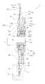
- FIG. 1 is a cross-sectional view of a clutch disk assembly according to an embodiment of the present invention.
- Side view of low rigidity damper unit (excluding holder plate) Exploded sectional view of low rigidity damper unit
- FIG. 8 is a cross-sectional view in a direction orthogonal to a cutting line VIII A-VIII A in FIG.
- FIG. 7 Sectional drawing of the direction orthogonal to the cutting line IX
- FIG. 1 shows a clutch disk assembly 1 having a clutch structure according to an embodiment of the present invention.
- FIG. 1 is a sectional view of the clutch disk assembly 1
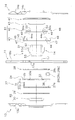
- FIG. 2 is a front view thereof.
- the clutch disc assembly 1 is used in a vehicle clutch device.
- OO is the rotation axis of the clutch disk assembly 1, that is, the rotation center line.
- a direction away from the rotation axis O is referred to as a radial direction
- a direction along the rotation axis is referred to as an axial direction.
- the direction around the rotation axis O is referred to as a circumferential direction or a rotation direction.
- the engine and flywheel 6 are arranged on the left side of FIG. 1, and a transmission (not shown) is arranged on the right side of FIG.
- the R1 side in FIG. 2 is the rotational direction drive side (positive side) of the clutch disk assembly 1, and the R2 side is the opposite side (negative side).
- the clutch disc assembly 1 attenuates the torque fluctuation input from the engine and transmits it to the transmission side.
- the clutch disk assembly 1 mainly has a damper part 100 and a clutch part 101 (an example of a clutch structure).
- the damper unit 100 includes a high-rigidity damper unit 2, a low-rigidity damper unit 3, a hub 4, and a hysteresis torque generation mechanism 5.
- High rigidity damper unit Torque from the engine is input to the high rigidity damper unit 2.
- the high rigidity damper unit 2 substantially operates in a high torsion angle region H (see FIG. 10) of torsional characteristics.
- the high-rigidity damper unit 2 includes a first input side member 10, a first flange 11, and a plurality of (for example, four) high-rigidity spring units 12.
- the first input side member 10 includes, for example, a clutch plate 13 and a retaining plate 14.
- the clutch plate 13 and the retaining plate 14 are substantially circular disk members.
- the clutch plate 13 and the retaining plate 14 are arranged at a predetermined interval in the axial direction.
- the clutch plate 13 is disposed on the engine side, and the retaining plate 14 is disposed on the transmission side.
- the clutch plate 13 and the retaining plate 14 are connected to each other by a fixing member such as a pin member 16 so as to be integrally rotatable.
- window holes 13a and 14a are formed in the outer peripheral portions of the clutch plate 13 and the retaining plate 14 at equal intervals in the rotation direction.
- a high-rigidity spring unit 12 is disposed in each of the window holes 13a and 14a. Both end portions of the high-rigidity spring unit 12 are in contact with the wall portions facing each other in the circumferential direction in each of the window holes 13a and 14a.
- raised portions are formed on the inner peripheral side and the outer peripheral side, respectively.
- the retaining plate 14 has a plurality of (for example, four) support holes 14b.
- the plurality of support holes 14 b are for supporting the hysteresis torque generating mechanism 5.
- a protrusion 45 of the first bush 40 in the hysteresis torque generating mechanism 5 described later is inserted into each support hole 14b.
- the first flange 11 is configured to be rotatable relative to the first input side member 10.
- the first flange 11 is disposed on the outer peripheral portion of the hub 4.
- the first flange 11 extends radially outward from the hub 4 and is formed in a substantially annular shape in the circumferential direction.
- the first flange 11 is formed separately from the hub 4.
- the first flange 11 is rotatable relative to the hub 4 in a predetermined torsion angle range, for example, a low torsion angle region L (see FIG. 10). Further, the first flange 11 can rotate integrally with the hub 4 outside a predetermined twist angle range, for example, in a high twist angle region H.
- the twist angle is defined by, for example, the twist angle (relative rotation angle) of the first flange 11 with respect to the hub 4.
- the torsion angle is, for example, the second angle with respect to the hub 4. It can be said that it is defined by the twist angle (relative rotation angle) of the two input side members (first holder plate and second holder plate).
- the first flange 11 is disposed between the axial direction of the clutch plate 13 and the retaining plate 14.
- the first flange 11 includes a first hole portion 17, a plurality of (for example, four) first spring accommodating portions 18, a plurality of (for example, two) first concave portions 19, and a stopper projection 20.
- the first hole 17 is formed at the center of the first flange 11.
- the hub 4 can be inserted into the first hole 17.
- a plurality of internal teeth 17 a are formed in the first hole portion 17.
- a plurality of external teeth 51a formed on the large diameter portion 51 of the hub 4 can mesh with the plurality of internal teeth 17a.
- each outer tooth 51a of the hub 4 is disposed between two inner teeth 17a adjacent to each other in the circumferential direction.
- a gap is formed between the two inner teeth 17 a adjacent to each other in the circumferential direction and the outer teeth 51 a of the hub 4 in the circumferential direction.
- the plurality of first spring accommodating portions 18 are formed on the outer peripheral portion of the first flange 11. Specifically, the plurality of first spring accommodating portions 18 are formed at equal intervals in the circumferential direction. Each first spring accommodating portion 18 is formed with an opening 18a. Each opening 18a is disposed so as to face the window holes 13a, 14a of the clutch plate 13 and the retaining plate 14 in the axial direction. The highly rigid spring unit 12 is disposed in the opening 18a. The both ends of each high-rigidity spring unit 12 are in contact with the wall portion facing in the circumferential direction in the opening 18a.
- a claw portion 31 (described later) of the first holder plate is engaged with each of the plurality of first recesses 19.
- Each first recess 19 is formed on the inner peripheral edge of each of the two openings 18a that are opposed to each other in the radial direction.
- Each first concave portion 19 is formed in a concave shape toward the rotation axis O at the circumferential central portion at the inner peripheral edge of the opening 18a.
- the stopper projection 20 protrudes outward from the outer peripheral surface of the first spring accommodating portion 18 at the circumferential center of the outer peripheral surface of the first spring accommodating portion 18.
- a pin member 16 that fixes the clutch plate 13 and the retaining plate 14 can come into contact with the stopper projection 20.
- the rotation of the first flange 11 with respect to the clutch plate 13 and the retaining plate 14 is restricted by the contact of the stopper projection 20 and the pin member 16. That is, the stopper projection 20 and the pin member 16 function as a stopper mechanism for the first flange 11.
- the plurality of high-rigidity spring units 12 elastically connect the first input side member 10 and the first flange 11 in the rotation direction. Specifically, the plurality of high-rigidity spring units 12 elastically connect the clutch plate 13 and the retaining plate 14 to the first flange 11 in the rotational direction.
- Each high-rigidity spring unit 12 has higher rigidity than each low-rigidity spring unit 25 (described later).
- each high-rigidity spring unit 12 includes a high-rigidity first spring 21 and a high-rigidity second spring 22.
- the combined rigidity of the high rigidity first spring 21 and the high rigidity second spring 22 is higher than the rigidity of each low rigidity spring unit 25.
- the high rigidity second spring 22 is disposed on the inner peripheral portion of the high rigidity first spring 21.
- the high rigidity second spring 22 has substantially the same length as the high rigidity first spring 21.
- the high rigidity first spring 21 and the high rigidity second spring 22 are accommodated in the openings 18 a of the first flange 11. Specifically, the movement of the first spring 21 for high rigidity and the second spring 22 for high rigidity is restricted in the radial direction and the axial direction by the window holes 13 a and 14 a of the clutch plate 13 and the retaining plate 14. .
- both end portions of the high rigidity first spring 21 and both end portions of the high rigidity second spring 22 are in contact with the wall portions facing each other in the circumferential direction in each opening 18 a of the first flange 11. Further, both end portions of the high rigidity first spring 21 and both end portions of the high rigidity second spring 22 are wall portions facing each other in the circumferential direction in the window holes 13a and 14a of the clutch plate 13 and the retaining plate 14, respectively. It is in contact.
- the high rigidity first spring 21 and the high rigidity second spring 22 elastically connect the clutch plate 13 and the retaining plate 14 to the first flange 11 in the rotational direction.
- the plurality of high-rigidity spring units 12 having the above-described configuration substantially operate within a range of a high torsion angle region H (see FIG. 10) of torsion characteristics.
- the plurality of high-rigidity spring units 12, that is, the high-rigidity first spring 21 and the high-rigidity second spring 22 are not less than the second torsion angle A2 and less than the third torsion angle A3 in the high torsion angle region H.
- the operation mode of the high-rigidity spring unit 12 will be described in detail in the following [Operation of Clutch Disc Assembly].
- the low rigidity damper unit 3 is configured to have a lower rigidity than the high rigidity damper unit 2.
- the low rigidity damper unit 3 functions as a pre-damper.
- the low rigidity damper unit 3 is disposed between the first input side member 10 and the first flange 11 on the inner peripheral side of the high rigidity spring unit 12.
- the low-rigidity damper unit 3 engages with the high-rigidity damper unit 2 and operates in a low torsion angle region L (see FIG. 10) of torsional characteristics.
- the low-rigidity damper unit 3 includes a second input-side member 23, a second flange 24 (an example of a second output-side member), and a plurality of (for example, two) low-rigidity springs.
- the unit 25 an example of a first elastic member and a second elastic member
- a pair of spring seats 26 an example of a connecting member
- the second input side member 23 is configured to be able to rotate integrally with the first flange 11.
- the second input side member 23 includes a first holder plate 27 and a second holder plate 28.
- the first holder plate 27 is a substantially annular disk member.
- the first holder plate 27 is configured to be able to engage with the first flange 11 and the second holder plate 28.
- the first holder plate 27 is disposed between the clutch plate 13 and the second flange 24 in the axial direction.
- the 1st holder plate 27 is arrange
- two window holes 27a and 28a are formed at equal intervals in the rotation direction.
- a low-rigidity spring unit 25 is disposed in each of the window holes 27a and 28a. Both end portions of the low-rigidity spring unit 25 (end portions of a pair of second low-rigidity springs 38 to be described later) are in contact with the wall portions facing each other in the circumferential direction in each of the window holes 27a and 28a.
- the first holder plate 27 has a plurality of claw portions 31 (an example of an engaging portion).
- Each of the plurality of (for example, two) claw portions 31 includes a first recess 19 of the first flange 11, a second recess 32 (described later) of the second holder plate 28, and a wide recess 35 (described later) of the second flange 24. To be engaged with each other.
- Each claw portion 31 is a portion extending in the axial direction from the outer peripheral portion of the first holder plate 27.
- Each claw portion 31 has a shaft portion 31a having a rectangular cross section and a tip portion 31b having a circumferential width smaller than that of the shaft portion 31a.
- the first holder plate 27 can rotate integrally with the first flange 11 by engaging the tip 31b of each claw portion 31 with each first recess 19. Further, the first holder plate 27 can rotate integrally with the second holder plate 28 by the shaft portions 31 a of the claw portions 31 engaging with the second recesses 32. Furthermore, the shaft part 31a of each nail
- the second holder plate 28 is a substantially annular disk member.
- the second holder plate 28 is disposed so as to face the first holder plate 27 in the axial direction.
- the second holder plate 28 is disposed between the first flange 11 and the second flange 24 in the axial direction.
- the second holder plate 28 is configured to be rotatable integrally with the first holder plate 27.
- the second holder plate 28 has a plurality of (for example, two) second recesses 32.
- the plurality of second recesses 32 are formed in the outer peripheral portion of the second holder plate 28 at equal intervals in the circumferential direction.
- the second holder plate 28 is engaged by the engagement between the shaft portion 31a of each claw portion 31 and each second recess 32, for example, the fitting between the shaft portion 31a of each claw portion 31 and each second recess 32. Can rotate integrally with the first holder plate 27.
- the second flange 24 is configured to be rotatable relative to the second input side member 23. As shown in FIG. 3, the second flange 24 is disposed between the first holder plate 27 and the second holder plate 28. The second flange 24 can rotate integrally with the hub 4.
- the second flange 24 has a second hole 33, a plurality of (for example, two) second spring accommodating portions 34, and a plurality of (for example, two) wide concave portions 35.
- the second hole 33 is formed at the center of the second flange 24.
- the hub 4 can be inserted into the second hole 33.
- a plurality of internal teeth 33 a are formed in the second hole 33.
- a plurality of external teeth 51a formed on the large-diameter portion 51 of the hub 4 can mesh with the plurality of internal teeth 33a.
- the second flange 24 is configured to be rotatable together with the hub 4.
- the plurality of second spring accommodating portions 34 are formed on the outer peripheral portion of the second flange 24. Specifically, the plurality of second spring accommodating portions 34 are formed at equal intervals in the circumferential direction. Each second spring accommodating portion 34 is formed with a notch portion 36. The notch 36 is formed in a concave shape toward the rotation axis O and opens outward in the radial direction.
- the low rigidity spring unit 25 is disposed in each notch 36. Both end portions of each low-rigidity spring unit 25 (end portions of a pair of second low-rigidity springs 38 to be described later) are in contact with the wall portions facing in the circumferential direction in the notch portion 36.
- each claw part 31 of the 1st holder plate 27 engages with each wide recessed part 35 so that a movement in the circumferential direction is possible.
- the wide concave portions 35 are formed at equal intervals in the circumferential direction on the outer peripheral portion of the second flange 24.
- the bottom of each wide recess 35 is formed in a substantially arc shape.
- the shaft portion 31 a of each claw portion 31 is movable in the circumferential direction along the bottom portion of each wide concave portion 35.
- the circumferential length of each wide concave portion 35 is set so that the shaft portion 31a of each claw portion 31 does not contact the wall portion of each wide concave portion 35 (wall portion of the wide concave portion 35). Is set. With this configuration, the first holder plate 27 can rotate relative to the second flange 24 together with the second holder plate 28 with which the tip portion 31 b of the claw portion 31 is engaged.
- each low-rigidity spring unit 25 elastically connect the second input side member 23 and the second flange 24 in the rotational direction. As shown in FIGS. 3 and 4, each low-rigidity spring unit 25 is provided in each second spring accommodating portion 34 of the second flange 24 and the window holes 27 a and 28 a of the first and second holder plates 27 and 28. Be placed. Each low-rigidity spring unit 25 has lower rigidity than each high-rigidity spring unit 12.
- each low-rigidity spring unit 25 includes a first low-rigidity spring 37 (an example of a first elastic member) and a pair of second low-rigidity springs 38 (second An example of an elastic member).
- the first low-rigidity spring 37 and the pair of second low-rigidity springs 38 elastically connect the second input side member 23 and the second flange 24 in the rotational direction.
- the first low-rigidity spring 37 is disposed in the notch portion 36 of the second spring accommodating portion 34.
- the first low-rigidity spring 37 is disposed between the pair of second low-rigidity springs 38 in the circumferential direction, and operates in series with each of the second low-rigidity springs 38.
- the first low-rigidity spring 37 has lower rigidity than the second low-rigidity spring 38.
- the first low-rigidity spring 37 operates substantially below the first torsion angle A1 in the low torsion angle region L (see FIG. 10).
- the pair of second low-rigidity springs 38 are disposed in the notch portion 36 of the second spring accommodating portion 34 and the window holes 27a and 28a of the first holder plate 27 and the second holder plate 28.
- Each of the pair of second low-rigidity springs 38 is arranged in series with the first low-rigidity spring 37.
- each of the pair of second low-rigidity springs 38 is disposed on both sides of the first low-rigidity spring 37 in the circumferential direction. That is, one end portion of each second low-rigidity spring 38 is disposed so that both end portions of the first low-rigidity spring 37 can be pressed in the circumferential direction via the spring seat 26.
- each second low-rigidity spring 38 has a wall portion of the notch portion 36 of the second spring accommodating portion 34, and the window holes 27 a and 28 a of the first holder plate 27 and the second holder plate 28. It abuts against the wall.
- Each of the pair of second low-rigidity springs 38 thus configured has higher rigidity than the first low-rigidity spring 37.
- the pair of second low-rigidity springs 38 substantially operate at a first torsion angle A1 or more and less than a second torsion angle A2 in the low torsion angle region L (see FIG. 10).
- each of the pair of spring seats 26 is disposed between a first low-rigidity spring 37 and a second low-rigidity spring 38.
- the pair of spring seats 26 includes a first spring seat 26a and a second spring seat 26b.
- the first spring seat 26 a is disposed between one of the pair of first low-rigidity springs 37 and the second low-rigidity spring 38 in the circumferential direction.
- the second spring seat 26b is disposed between the other of the pair of first low-rigidity springs 37 and the second low-rigidity spring 38 in the circumferential direction.
- the first spring seat 26a and the second spring seat 26b can contact each other in the circumferential direction in the low twist angle region L. For example, when the twist angle reaches a predetermined angle, for example, the first twist angle A1 in the low twist angle region L, the first spring seat 26a and the second spring seat 26b come into contact with each other. As a result, the operation of the first low-rigidity spring 37 is stopped. That is, the first spring seat 26 a and the second spring seat 26 b function as a stopper mechanism for the second low-rigidity spring 38.
- the hub 4 is configured to be connectable to the transmission.
- the hub 4 is a substantially cylindrical member. As shown in FIGS. 3 and 5, on the outer peripheral surface of the hub 4, there are a large diameter portion 51 formed at the central portion in the axial direction, and a first small diameter portion 52 and a second small diameter formed at both ends in the axial direction. Part 53.
- a plurality of external teeth 51 a are formed on the outer peripheral surface of the large diameter portion 51.
- the external teeth 51 a of the large diameter portion 51 are formed over the entire length of the large diameter portion 51 in the axial direction.
- the internal teeth 33a of the second flange 24 are engaged with the external teeth 51a.
- the inner teeth 17a of the first flange 11 are engaged with the outer teeth 51a so as to be able to come into contact with each other at a predetermined twist angle, for example, a second twist angle A2.
- the first small diameter portion 52 is formed on the retaining plate 14 side of the large diameter portion 51.
- the second small diameter part 53 is formed on the clutch plate 13 side of the large diameter part 51.
- a sliding boss 30 is disposed on the outer peripheral portion of the second small diameter portion 53.
- a first holder plate 27 and a sliding plate 29 are disposed on the outer periphery of the sliding boss 30.
- the torque is substantially transmitted from the low rigidity damper unit 3 to the hub 4 in the low torsion angle region L. Further, torque is transmitted from the high rigidity damper unit 2 to the hub 4 in the high torsion angle region H.
- the hub 4 and the second flange 24 rotate integrally in the low torsion angle region L. Is possible.
- the low torsional angle region L the plurality of external teeth 51a of the hub 4 and the internal teeth of the plurality of 17a of the first flange 11 are not in contact with each other due to the gaps described above.
- the flange 11 is relatively rotatable. In the high torsion angle region H, the plurality of external teeth 51a of the hub 4 and the plurality of internal teeth 17a of the first flange 11 are in contact with each other, so that the hub 4 and the first flange 11 can rotate together. .
- This configuration allows the hub 4 to substantially transmit torque from the second flange 24 of the low-rigidity damper unit 3 in the low torsion angle region L. Further, in the hub 4, torque is transmitted from the first flange 11 of the high rigidity damper unit 2 in the high torsion angle region H.
- the hysteresis torque generating mechanism 5 includes a first hysteresis torque generating mechanism 61 and a second hysteresis torque generating mechanism 62.
- the first hysteresis torque generation mechanism 61 is disposed between the first input side member 10 (the retaining plate 14) and the first flange 11 in the axial direction on the inner peripheral side of the high-rigidity spring unit 12.
- the first hysteresis torque generating mechanism 62 includes a first bush 40, a first urging member 41, a second bush 42, and a second urging member 43. ing.
- the first bush 40 is configured to be movable in the axial direction with respect to the retaining plate 14.
- the first bush 40 is urged toward the first flange 11 by the first urging member 41.
- the first bush 40 is formed in a substantially annular shape. As shown in FIG. 5, the first bush 40 includes a first annular portion 44, a plurality of (for example, four) protruding portions 45, a contact portion 46, and a first sliding portion 47.
- the first annular portion 44 is disposed on the radially outer side of the hub 4.
- the hub 4 is disposed on the inner peripheral portion of the first annular portion 44.
- the inner peripheral surface of the first annular portion 44 and the outer peripheral portion of the hub 4 are arranged at a predetermined interval in the radial direction.
- first bush 40 positions the second bush 42 in the radial direction.
- Each of the plurality of projecting portions 45 projects from the first annular portion 44 in the axial direction. Specifically, each of the plurality of protruding portions 45 protrudes in the axial direction from the first annular portion 44 toward the retaining plate 14.
- the plurality of protrusions 45 support the first biasing member 41.
- the first urging member 41 is disposed on the outer peripheral portion of the plurality of projecting portions 45 and positions the first urging member 41 in the radial direction.
- each protrusion 45 is inserted into the support hole 14b of the retaining plate 14 (see FIG. 1).
- Each protrusion 45 is movable in the axial direction with respect to the support hole 14b.
- Each protrusion 45 is immovable in the circumferential direction and the radial direction with respect to the support hole 14b. Accordingly, the first bush 40 is supported so as to be movable in the axial direction with respect to the retaining plate 14 and is supported so as not to be movable in the circumferential direction and the radial direction.
- the abutting portion 46 is a portion with which the first urging member 41 abuts.
- the contact part 46 is provided on the outer peripheral part of the first annular part 44. Specifically, the contact portion 46 is formed on the outer peripheral portion of the first annular portion 44 on the radially outer side of the plurality of protruding portions 45.
- the first sliding portion 47 is a portion that contacts and slides on the side surface of the first flange 11.
- the first sliding portion 47 is provided on the outer peripheral portion of the first annular portion 44.
- the first sliding portion 47 is provided on the outer surface of the first annular portion 44 on the surface opposite to the protruding portion 45.
- the first biasing member 41 is, for example, a cone spring.
- the first urging member 41 is disposed between the axial direction of the retaining plate 14 and the first bush 40. Specifically, the first biasing member 41 is disposed between the retaining plate 14 and the axial direction of the contact portion 46 of the first bush 40.
- the first urging member 41 is compressed in the axial direction, and one end in the axial direction contacts the retaining plate 14, and the other end in the axial direction contacts the contact 46 of the first bush 40. . Thereby, the first urging member 41 urges the first bush 40 toward the first flange 11.
- an outer peripheral portion of the first bush 40 for example, a plurality of protruding portions 45 is disposed on the inner peripheral portion of the first biasing member 41. Thereby, the first urging member 41 is positioned in the radial direction by the first bush 40.
- the second bush 42 is configured to be movable in the axial direction with respect to the retaining plate 14.
- the second bush 42 is pressed against the hub 4, for example, the large diameter portion 51 by the second urging member 43.
- the second bush 42 is disposed on the inner peripheral portion of the first bush 40.
- the second bush 42 is formed in a substantially annular shape.
- the second bush 42 includes a second annular part 48, a second sliding part 49, and an annular convex part 50.
- the second annular portion 48 is disposed between the hub 4 and the first annular portion 44 in the radial direction.
- the second sliding portion 49 is a portion that contacts and slides on the side surface of the large-diameter portion 51 of the hub 4.
- the second sliding portion 49 is provided on the surface of the second annular portion 48 that faces the large diameter portion 51 of the hub 4.
- the annular convex portion 50 protrudes in the axial direction from the inner peripheral portion of the second annular portion 48 and is formed in an annular shape in the circumferential direction. Specifically, the annular protrusion 50 protrudes in the axial direction from the inner peripheral portion of the second annular portion 48 toward the retaining plate 14. A predetermined gap is provided between the distal end portion 31 b of the annular convex portion 50 and the axial direction of the retaining plate 14. An annular step 50 a is formed at the base end of the annular protrusion 50. The second urging member 43 abuts on the stepped portion 50a.
- the second urging member 43 is, for example, a cone spring.
- the second urging member 43 is disposed between the retaining plate 14 and the second bush 42 in the axial direction. Specifically, the second urging member 43 is disposed between the retaining plate 14 and the stepped portion of the second bush 42 in the axial direction.
- the second urging member 43 In the state where the second urging member 43 is compressed in the axial direction, one end portion in the axial direction contacts the retaining plate 14 and the other end portion in the axial direction contacts the stepped portion 50a of the second bush 42.
- the second bushing 42 is biased toward the hub 4 by the second biasing member 43.
- the inner peripheral portion of the second urging member 43 is disposed on the inner peripheral portion of the second bush 42, for example, the annular convex portion 50. Thereby, the second urging member 43 is positioned in the radial direction by the second bush 42.
- hysteresis torque is generated by the sliding of the second bush 42 in the low torsion angle region L, and the hysteresis torque is generated by the sliding of the first bush 40 in the high torsion angle region H. appear.
- the second hysteresis torque generating mechanism 62 is disposed between the first input side member 10 (clutch plate 13) and the first flange 11 in the axial direction on the inner peripheral side of the high-rigidity spring unit 12.
- the second hysteresis torque generating mechanism 62 has a sliding boss 30 and a sliding plate 29.
- the sliding boss 30 is substantially cylindrical.
- the sliding boss 30 is disposed between the first holder plate 27 and the hub 4 (second small diameter portion 53 described later) in the radial direction.
- the sliding boss 30 is disposed between the sliding plate 29 and the hub 4 (second small diameter portion 53) in the radial direction.
- the sliding boss 30 is disposed between the inner peripheral portion of the clutch plate 13 and the axial direction of the large diameter portion 51 of the hub 4.
- the sliding boss 30 is in contact with the inner peripheral portion of the clutch plate 13 and the large diameter portion 51 of the hub 4 in the axial direction. As a result, when the clutch plate 13 and the hub 4 are rotated relative to each other, the sliding boss 30 slides on at least one of the clutch plate 13 and the hub 4 to generate hysteresis torque.
- the sliding plate 29 is a substantially annular disk member.
- the sliding plate 29 is disposed between the first holder plate 27 and the clutch plate 13 in the axial direction. Further, the sliding plate 29 is disposed on the outer peripheral portion of the sliding boss 30.
- the sliding plate 29 is in contact with the clutch plate 13 and the first holder plate 27 in the axial direction. As a result, when the clutch plate 13 and the first holder plate 27 rotate relative to each other, the sliding plate 29 slides on at least one of the clutch plate 13 and the first holder plate 27, and hysteresis torque is generated.
- the first holder plate 27 can rotate integrally with the first flange 11 via the claw portion 31, when the clutch plate 13 and the first flange 11 rotate relative to each other, the sliding plate 29 moves to the clutch plate 13. And slides with at least one of the first holder plate 27 to generate hysteresis torque.
- hysteresis torque is generated by sliding of the sliding boss 30 in the low torsion angle region L, and hysteresis torque is generated by sliding of the sliding plate 29 in the high torsion angle region H. appear.
- the clutch portion 101 is a portion that is pressed against the flywheel 6 by the pressure plate 7. Specifically, the clutch portion 101 is disposed between the flywheel 6 disposed on the engine side and the pressure plate 7 disposed on the transmission side. In this state, the clutch portion 101 is pressed by the pressure plate 7 and pressed against the flywheel 6.
- the flywheel 6 and the pressure plate 7 are indicated by broken lines only in the lower part, and the upper flywheel 6 and the pressure plate 7 are omitted.
- the clutch unit 101 includes a cushioning plate 70 (an example of a support member), a pair of friction facings 71 (an example of a contact member), and a plurality of connecting members 74.
- the cushioning plate 70 As shown in FIG. 1, the cushioning plate 70 is fixed to the clutch plate 13.
- the cushioning plate 70 is configured to be elastically deformable.
- the cushioning plate 70 is substantially formed in an annular plate shape.
- the cushioning plate 70 supports a pair of friction facings 71.
- the cushioning plate 70 is disposed between the pair of friction facings 71 and elastically supports each of the pair of friction facings 71.
- the cushioning plate 70 includes a fixing portion 81 (an example of a main body portion), a plurality of attachment portions 82 (an example of a main body portion), and a plurality of detection portions 83. is doing.
- the fixing portion 81 is a portion that is fixed to the clutch plate 13.
- the fixing portion 81 is fixed to the clutch plate 13 by fixing means, for example, welding.
- a pair of friction facings 71 are attached to the plurality of attachment portions 82.
- the mounting portions 82 are arranged side by side in the circumferential direction on the radially outer side of the fixed portion 81 (see FIG. 1).
- Each mounting portion 82 is integrally formed on the outer peripheral portion of the fixed portion 81.
- Each mounting portion 82 is bent into a substantially wave shape in the circumferential direction.
- Each attachment portion 82 includes first and second flat portions 84 and 85, an intermediate portion 86, and first and second posture holding portions 87 and 88.
- a friction facing 71 that contacts the flywheel 6, for example, a first friction facing 72 (described later) is attached to each first flat portion 84.
- a friction facing 71 that contacts the pressure plate 7, for example, a second friction facing 73 (described later) is attached to each second flat portion 85.
- Each second flat portion 85 is disposed at a distance from the first flat portion 84 in the circumferential direction, and is offset from the first flat portion 84 in the axial direction.
- each first flat portion 84 has a first hole portion 84a (an example of a first hole portion).
- the first hole portion 84a penetrates each first flat portion 84 in the axial direction.
- a connecting member 74 (a first connecting member 75 to be described later) for attaching the first friction facing 72 to the first flat portion 84 is disposed in the first hole portion 84a.
- each second flat portion 85 has a second hole portion 85a (an example of the first hole portion).
- the second hole 85a penetrates each second flat portion 85 in the axial direction.
- a connecting member 74 (second connecting member 76 described later) for attaching the second friction facing 73 to the second flat portion 85 is disposed in the second hole 85a.
- the intermediate portion 86 is a portion that connects the first flat portion 84 and the second flat portion 85.
- the intermediate portion 86 connects the first flat portion 84 and the second flat portion 85 in the circumferential direction with the first flat portion 84 and the second flat portion 85 being offset in the axial direction.
- the intermediate portion 86 extends from the circumferential end of the first flat portion 84 toward the second friction facing 73 and is connected to the second flat portion 85. In other words, the intermediate portion 86 extends from the circumferential end of the second flat portion 85 toward the first friction facing 72 and is connected to the first flat portion 84.
- the first posture holding portion 87 is a portion that holds the posture of the first flat portion 84.
- the first posture holding portion 87 is integrally provided at the circumferential end of the first flat portion 84.
- the first posture holding portion 87 extends toward the second friction facing 73 and is configured to be able to contact the second friction facing 71.
- the second posture holding portion 8882e is integrally provided at the circumferential end of the second flat portion 85.
- the second posture holding portion 8882 e extends toward the first friction facing 72 and is formed so as to be able to contact the first friction facing 72.
- each of the plurality of detection units 83 is a part that detects wear of the friction facing 71.
- Each detection part 83 is provided in the attachment part 82.
- each detection unit 83 is provided in the first flat portion 84 and the second flat portion 85.
- the detection part 83 provided in the 1st flat part 84 is described as the 1st detection part 83a.
- the detection part 83 provided in the 2nd flat part 85 is described as the 2nd detection part 83b.
- the first detection portion 83 a is provided in the first hole portion 84 a of the first flat portion 84.
- the first detection portion 83a extends from the inner peripheral portion of the first hole portion 84a toward the flywheel 6.
- the first detection unit 83a is formed in a rectangular plate shape and protrudes toward the flywheel 6 from the inner peripheral portion of the first hole portion 84a.
- the first detection unit 83a is disposed between the first flat part 84 and a first contact surface 72a (described later) of the friction facing 71 that contacts the flywheel 6. Is done.
- the distal end portion of the first detection portion 83a is disposed between the first flat portion 84 and the first contact surface 72a.
- the tip of the first detection unit 83a is disposed in a third hole 72b (described later) of the friction facing 71 (first friction facing 72).
- the second detection portion 83 b is provided in the second hole 85 a of the second flat portion 85.
- the second detector 83b extends from the inner peripheral part of the second hole 85a toward the pressure plate 7.
- the second detection unit 83b is formed in a rectangular plate shape and protrudes toward the flywheel 6 from the inner peripheral portion of the second hole portion 84b.
- the second detection portion 83b is disposed between the second flat portion 85 and a second contact surface 73a (described later) of the friction facing 71 that contacts the pressure plate 7. Is done.
- the distal end portion of the second detection portion 83b is disposed between the second flat portion 85 and the second contact surface 73a.
- the tip of the second detection unit 83b is disposed in a fifth hole 73b (described later) of the friction facing 71 (second friction facing 73).
- each of the pair of friction facings 71 is configured to be able to contact the flywheel 6 or the pressure plate 7.
- Each of the pair of friction facings 71 is fixed to both surfaces of the cushioning plate 70.
- Each of the pair of friction facings 71 is worn by contact with the flywheel 6 or the pressure plate 7.
- the friction facing 71 is composed of an organic material such as fiber and / or synthetic resin, hard particles, and lubricating particles such as graphite.
- the friction facing 71 may be composed of an inorganic material, for example, a base material such as copper, nickel, and tin, hard particles, and lubricating particles such as graphite.
- the pair of friction facings 71 includes a first friction facing 72 and a second friction facing 73.
- the first friction facing 72 is substantially formed in an annular plate shape.
- the first friction facing 72 is fixed to the flywheel 6 side surface of the cushioning plate 70.
- the first friction facing 72 includes a first contact surface 72a (an example of a contact surface), a plurality of third hole portions 72b (an example of a second hole portion), and a plurality of first contact surfaces. 4 holes 72c (see FIGS. 9A and 9B).
- the first contact surface 72 a is arranged to face the flywheel 6 and can contact the flywheel 6. For example, when the clutch portion 101 is pressed toward the flywheel 6 by the pressure plate 7, the first contact surface 72 a contacts the flywheel 6.
- the third hole portions 72b are arranged at intervals in the circumferential direction and penetrate the first friction facing 72 in the axial direction.
- the third hole 72b is, for example, a tapered hole. Specifically, in the third hole portion 72b, the inner diameter of the third hole portion 72b gradually decreases from the first contact surface 72a toward the cushioning plate 70 (first flat portion 84).
- Each 3rd hole 72b is arranged facing each 1st hole 84a of cushioning plate 70 (1st flat part 84).
- each of the third holes 72b at least a part of the first detector 83a, for example, the tip of the first detector 83a is disposed.
- a connection member 74 (a first connection member 75 described later) is disposed in each third hole 72b.
- Each of the fourth hole portions 72c is a work hole portion used when a connecting member 74 (second connecting member 76 described later) is attached.
- each fourth hole 72 c is a hole used when heating the second connecting member 76.
- Each fourth hole 72c is disposed away from the third hole 72b in the circumferential direction, and penetrates the first friction facing 72 in the axial direction.
- Each 4th hole part 72c is arrange
- each fourth hole 72 c is disposed to face each fifth hole 73 b (described later) of the second friction facing 73.
- the second friction facing 73 is substantially formed in an annular plate shape.
- the second friction facing 73 is fixed to the surface of the cushioning plate 70 on the pressure plate 7 side.
- the second friction facing 73 includes a second contact surface 73a (an example of a contact surface), a plurality of fifth hole portions 73b (an example of second hole portions), and a plurality of second contact surfaces 73a. 6 holes 73c (calculation of FIGS. 8A and 8B).
- the second contact surface 73 a is disposed to face the pressure plate 7 and can contact the pressure plate 7. For example, when the clutch unit 101 is pressed toward the flywheel 6 by the pressure plate 7, the second contact surface 73 a contacts the pressure plate 7.
- the fifth holes 73b are arranged at intervals in the circumferential direction and penetrate the second friction facing 73 in the axial direction.
- the fifth hole 73b is, for example, a tapered hole.
- the inner diameter of the third hole portion 72b gradually decreases from the second contact surface 73a toward the cushioning plate 70 (second flat portion 85).
- Each fifth hole 73b is arranged to face each second hole 85a of the cushioning plate 70 (second flat portion 85). At least a part of the second detection unit 83b, for example, the tip of the second detection unit 83b is disposed in each fifth hole 73b. In addition, a connecting member 74 (second connecting member 76 described later) is disposed in each fifth hole 73b.
- Each 6th hole 73c is a hole for work used when attaching connecting member 74 (the 1st connecting member 75 mentioned below).
- each sixth hole 73 c is a hole used when the first connecting member 75 is heated.
- Each sixth hole 73c is disposed away from the fifth hole 73b in the circumferential direction, and penetrates the second friction facing 73 in the axial direction.
- Each sixth hole 73c is arranged to face each first hole 84a of the cushioning plate 70 (first flat portion 84).
- each sixth hole 73 c is disposed to face each third hole 72 b of the first friction facing 72.
- each of the plurality of connecting members 74 is configured to be able to connect a pair of friction facings 71 and a cushioning plate 70.
- Each of the plurality of connecting members 74 is configured to be able to contact and wear against the flywheel 6 or the pressure plate 7.
- the plurality of connecting members 74 are in contact with the third hole 72b (taper hole) and the fifth hole 73b (taper hole), respectively.
- a cushioning plate 70 is held. In other words, each of the plurality of connecting members 74 is retained by the cushioning plate 70.
- the plurality of connecting members 74 have a plurality of first connecting members 75 and a plurality of second connecting members 76.
- Each first connecting member 75 is disposed in each first hole 84 a of the cushioning plate 70 (first flat portion 84) and each third hole 72 b of the first friction facing 72.
- Each first connecting member 75 is configured to be able to contact and wear against the flywheel 6. Each first connecting member 75 is prevented from being detached by each first detecting portion 83 a of the cushioning plate 70. Specifically, each first connecting member 75 is prevented from being detached by each first detection portion 83a of the cushioning plate 70 and the inner peripheral portion of each first hole portion 84a.
- Each first connecting member 75 has a third contact surface 75a.
- the third contact surface 75 a is disposed to face the flywheel 6 and can contact the flywheel 6.
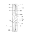
- the third contact surface 75 a is formed on the same plane as the first contact surface 72 a of the first friction facing 72. For example, when the clutch part 101 is pressed to the flywheel 6 side by the pressure plate 7, the 3rd contact surface 75a contacts the flywheel 6 with the 1st contact surface 72a.
- the first connecting member 75 is made of, for example, a synthetic resin.
- the 1st connection member 75 is comprised from a thermosetting resin.
- each first hole of the cushioning plate 70 so that each first connecting member 75 softened by heating sandwiches each first detection portion 83a of the cushioning plate 70 and the inner periphery of each first hole 84a. 84a and each third hole 72b of the first friction facing 72.
- each first connecting member 75 is further heated, each first connecting member 75 is cured.
- the first connecting member 75 connects the cushioning plate 70 and the first friction facing 72.
- the 1st connection member 75 is heated from the 3rd contact surface 75a side of each 1st connection member 75, and each 6th hole 73c side.
- the hardness of the first connecting member 75 for example, the hardness of the thermosetting resin is equal to or less than the hardness of the first friction facing 72. Accordingly, when the third contact surface 75 a of the first connecting member 75 comes into contact with the flywheel 6 together with the first contact surface 72 a of the first friction facing 72, the first connecting member 75 is worn together with the first friction facing 72. . Then, when wear of the first connecting member 75 progresses and the first detection portion 83a of the cushioning plate 70 contacts the flywheel 6, the first friction facing 72 is replaced.
- Each second connecting member 76 is disposed in each second hole 85 a of the cushioning plate 70 (second flat portion 85) and each fifth hole 73 b of the second friction facing 73.
- Each second connecting member 76 is configured to be able to contact and wear against the pressure plate 7. Each second connecting member 76 is prevented from being detached by each second detecting portion 83 b of the cushioning plate 70. In detail, each 2nd connection member 76 is prevented by the inner peripheral part of each 2nd detection part 83b of each cushioning plate 70, and each 2nd hole 85a.
- Each second connecting member 76 has a fourth contact surface 76a.
- the fourth contact surface 76 a is disposed to face the pressure plate 7 and can contact the pressure plate 7.
- the fourth contact surface 76 a is formed on substantially the same surface as the second contact surface 73 a of the second friction facing 73. Thereby, for example, when the clutch portion 101 is pressed toward the flywheel 6 by the pressure plate 7, the fourth contact surface 76a contacts the pressure plate 7 together with the second contact surface 73a.
- the second connecting member 76 is made of, for example, a synthetic resin.
- the 2nd connection member 76 is comprised from a thermosetting resin.
- each second hole of the cushioning plate 70 is held such that each second connecting member 76 softened by heating sandwiches each second detection portion 83b of the cushioning plate 70 and the inner periphery of each second hole 85a. 85a and the fifth holes 73b of the second friction facing 71a.
- each second connecting member 76 is further heated, each second connecting member 76 is cured.
- the cushioning plate 70 and the second friction facing 73 are connected by the second connecting members 76.
- the 1st connection member 75 is heated from the 3rd contact surface 75a side of each 1st connection member 75, and each 6th hole 73c side.
- the hardness of the second connecting member 76 for example, the hardness of the thermosetting resin is equal to or less than the hardness of the second friction facing 73. Accordingly, when the fourth contact surface 76 a of the second connecting member 76 comes into contact with the flywheel 6 together with the second contact surface 73 a of the second friction facing 71 a, the second connecting member 76 is worn together with the second friction facing 73. . When the second connecting member 76 wears and the second detecting portion 83b of the cushioning plate 70 contacts the pressure plate 7, the second friction facing 73 is replaced.
- the rigidity of the high-rigidity damper unit 2 is higher than that of the low-rigidity damper unit 3.
- the damper unit 3 operates first.
- the clutch plate 13, retaining plate 14, and a plurality of high-rigidity springs when the input side clutch plate 13 and retaining plate 14 begin to twist to the R1 side with respect to the hub 4, the clutch plate 13, retaining plate 14, and a plurality of high-rigidity springs.
- the unit 12 and the first flange 11 rotate substantially integrally.
- the first flange 11 rotates relative to the hub 4, so that the rotation of the first flange 11 is not transmitted to the hub 4.
- the first low-rigidity spring 37 whose rigidity is lower than that of the second low-rigidity spring 38 is substantially operated. Specifically, when the first torsion angle A1 is less than the first torsion angle A1 in the low torsion angle region L, the first low-rigidity spring 37 is located between the first holder plate 27 and the second holder plate 28 and the second flange 24 in the circumferential direction. It works substantially. That is, when the angle is less than the first torsion angle A1, the torque fluctuation is mainly damped by the first low-rigidity spring 37. Thus, the first stage torsional rigidity K1 is formed by the operation of the first low-rigidity spring 37.
- the torque variation is attenuated by the second low-rigidity spring 38 at the first torsion angle A1 or more and less than the second torsion angle A2.
- the second torsional rigidity K2 is formed by the operation of the second low-rigidity spring 38.
- the first low-rigidity spring 37 or the second low-rigidity spring 38 is operated, and torque is transmitted from the second flange 24 to the hub 4.
- the second bush 42 of the first hysteresis torque generating mechanism 61 slides and the second hysteresis torque generating mechanism.
- Hysteresis torque is generated by the sliding of the 62 sliding bosses 30.
- the plurality of high-rigidity spring units 12 of the high-rigidity damper unit 2 operate.
- the plurality of high rigidity spring units 12 include the clutch plate 13 and the retaining plate 14, the first flange 11, In between.
- the third stage torsional rigidity K3 is formed by the operation of the plurality of high-rigidity spring units 12.
- the first hysteresis is obtained.
- Hysteresis torque is generated by the sliding of the first bush 40 of the torque generating mechanism 61 and the sliding of the sliding plate 29 of the second hysteresis torque generating mechanism 62.
- the clutch portion 101 is pressed against the flywheel 6 by the pressure plate 7.
- the first contact surface 72a of the first friction facing 72 and the third contact surface 75a of the first connecting member 75, and the second contact surface 73a of the second friction facing 71a and the fourth of the second connecting member 76 are provided.
- the contact surface 76a is in contact with the flywheel 6 and the pressure plate 7 separately.
- the wear of the friction facing 71 (the first friction facing 72 and the second friction facing 73) can be detected by the detecting portion 83 (the first detecting portion 83a and the second detecting portion 83b) of the cushioning plate 70. it can. Further, by providing the cushioning plate 70 with the detection unit 83, the position where the friction facing 71 is detected can be easily managed. Furthermore, the friction facings 71 can be reduced in thickness by connecting the cushioning plate 70 and the friction facings 71 with the connecting members 74 (the first connecting member 75 and the second connecting member 76).
- a step D is formed between the first contact surface 72a of the first friction facing 72 and the third contact surface 75a of at least one first connecting member 75. May be.
- a step may be formed between the second contact surface 73 a of the second friction facing 73 and the fourth contact surface 76 a of at least one second connecting member 76.
- the configuration of the second connecting member 76 is not shown because it is substantially the same as the configuration of the first connecting member 75 shown in FIG.
- the cushioning plate 70 may be configured to have the third detection unit 83.
- the third detection unit 83 is provided on the cushioning plate 70.
- the third detection portion 83 is provided on the outer peripheral portion of the cushioning plate 70.
- the third detection unit 83 is formed by bending a part of the outer periphery of the cushioning plate 70.
- the third detector 83 is disposed in the first recess 72 d provided in the first friction facing 72. Even with this configuration, the third detection unit 83 can detect the wear of the first friction facing 72.
- the third detector 83 can detect the wear of the second friction facing 73 by arranging the third detector 83 in the second recess 73 d provided in the second friction facing 73.
- each of the first recess 72d and the second recess 73d may be a hole.
- a third hole 72b in which the first connecting member 75 is not disposed may be provided.
- the first detector 83a is arranged in a state of being exposed inside the third hole 72b. Even if comprised in this way, the abrasion of the 1st friction facing 72 can be detected by the 1st detection part 83a.
- the 2nd detection part 83b is arrange
- position the 2nd connection member 76 is substantially the same as the structure shown in FIG. 13, it is not illustrated.
- first friction facing 72 and / or the second friction facing 73 may be composed of a plurality of arc-shaped friction facings.
- each friction facing is attached to each attachment portion 82 of the cushioning plate 70 by each connection member 74 (the first connection member 75 and / or the second connection member 76).
- one of the first friction facing 72 and the second friction facing 73 may be fixed to the cushioning plate 70 in the same manner as in the above embodiment.
- one of the first friction facing 72 and the second friction facing 73 is fixed to the cushioning plate 70 by a conventional fixing means such as a rivet.
- the configuration of the above-described clutch 101 (an example of a clutch structure) is used as a connecting member that connects a piston (an example of a support member) and a friction facing (an example of a contact member) in a torque converter. May be.
- damper unit 100 includes the high-rigidity damper unit 2, the low-rigidity damper unit 3, the hub 4, and the hysteresis torque generating mechanism 5 has been described.
- the configuration of the damper unit 100 is not limited to the above-described embodiment, and any configuration may be used as long as the torque variation can be attenuated.
Landscapes
- Engineering & Computer Science (AREA)
- General Engineering & Computer Science (AREA)
- Mechanical Engineering (AREA)
- Physics & Mathematics (AREA)
- Acoustics & Sound (AREA)
- Aviation & Aerospace Engineering (AREA)
- Mechanical Operated Clutches (AREA)
Abstract
摩擦フェーシングを薄型化できるクラッチ構造体を、提供する。クラッチ部(101)は、摩擦フェーシング(71)と、クッショニングプレート(70)と、連結部材(74)とを、備える。摩擦フェーシング(71)は、フライホイール(6)及びプレッシャープレート(7)に接触可能に構成される。クッショニングプレート(70)は、摩擦フェーシング(71)を支持する。連結部材(74)は、摩擦フェーシング(71)及びクッショニングプレート(70)を連結する。連結部材(74)は、フライホイール(6)及びプレッシャープレート(7)に対して接触可能且つ摩耗可能に構成される。
Description
本発明は、クラッチ構造体及びクラッチディスク組立体に関する。
一般的に、車輌には、振動を抑制するために、クラッチディスク組立体が設けられている(特許文献1を参照)。例えば、クラッチディスク組立体は、クラッチ構造体を有している。クラッチ構造体は、摩擦フェーシング(接触部材)と、クッショニングプレート(支持部材)と、金属製のリベット(連結部材)とを、備えている。摩擦フェーシングは、金属製のリベットによって、クッショニングプレートに固定されている。
従来のクラッチ構造体では、摩擦フェーシングが、金属製のリベットによって、クッショニングプレートに固定されていた。このため、金属製のリベットの頭部に対する、プレッシャープレート(被接触部材)及びフライホイール(被接触部材)の当接を、避ける必要がある。このため、金属製のリベットの頭部と、摩擦フェーシングの摩擦面との間には、隙間が設けられている。言い換えると、この隙間の範囲において、摩擦フェーシングは摩耗する。
このように、従来のクラッチ構造体では、金属製のリベットの頭部と、プレッシャープレート及びフライホイールとの当接を避けた状態で、摩擦フェーシングを、プレッシャープレート及びフライホイールに接触させていた。このため、摩擦フェーシングの厚みが大きくなってしまうという問題があった。
本発明は、上記の問題に鑑みてなされたものであって、本発明の目的は、摩擦フェーシングを薄型化できるクラッチ構造体を、提供することにある。
(1)本発明の一側面に係るクラッチ構造体は、接触部材と、支持部材と、連結部材とを、備える。接触部材は、被接触部材に接触可能に構成される。支持部材は、接触部材を支持する。連結部材は、接触部材及び支持部材を連結し、被接触部材に対して接触可能且つ摩耗可能に構成される。
本クラッチ構造体では、連結部材によって接触部材及び支持部材が連結された状態で、接触部材及び連結部材の両方が、被接触部材に対して接触し摩耗する。すなわち、本クラッチ構造体では、従来技術のように連結部材及び被接触部材の当接を避ける必要がないので、摩擦フェーシングを薄型化することができる。
(2)本発明の別の側面に係るクラッチ構造体では、被接触部材に接触する接触部材の第1接触面が、被接触部材に接触する連結部材の第2接触面と、実質的に同一面上に形成されている。このように構成することによって、摩擦フェーシングを薄型化することができる。
(3)本発明の別の側面に係るクラッチ構造体では、被接触部材に対する接触部材の第1接触面と、被接触部材に接触する連結部材の第2接触面との間には、段差が形成されている。
この場合、まず、接触部材の第1接触面が、被接触部材に接触する。次に、接触部材の摩耗量が、段差に対応する摩耗量に到達した場合に、連結部材の第2接触面が被接触部材に接触する。これにより、連結部材が摩耗する。このように構成しても、摩擦フェーシングを薄型化することができる。
(4)本発明の別の側面に係るクラッチ構造体では、接触部材が、テーパ孔を有する。連結部材は、テーパ孔に接触した状態で、支持部材を保持する。これにより、連結部材は、接触部材及び支持部材を好適に連結することができる。
(5)本発明の別の側面に係るクラッチ構造体では、連結部材の硬度が、接触部材の硬度以下である。この構成によって、連結部材を、接触部材とともに、好適に摩耗させることができる。
(6)本発明の別の側面に係るクラッチ構造体では、連結部材の材質は、樹脂である。この構成によって、接触部材及び支持部材を、連結部材によって容易に連結することができる。また、連結部材を、接触部材とともに、好適に摩耗させることができる。
(7)本発明の別の側面に係るクラッチ構造体では、連結部材の材質が、熱可塑性の樹脂である。この構成によって、接触部材及び支持部材を、連結部材によって、より容易に連結することができる。また、連結部材を、接触部材とともに、好適に摩耗させることができる。
(8)本発明の一側面に係るクラッチディスク組立体は、上記の(1)から(7)のいずれか1つに記載のクラッチ構造体と、ダンパ部とを、備える。クラッチ構造体は、被接触部材に接触可能に構成される。ダンパ部は、被接触部材からクラッチ構造体に伝達されるトルク変動を減衰する。このように構成しても、上記と同様の効果を得ることができる。また、ダンパ部においてトルク変動を減衰することができる。
本発明では、クラッチ構造体及びクラッチディスク組立体において、摩擦フェーシングを薄型化することができる。
[全体構成]
図1には、本発明の一実施形態によるクラッチ構造体を有するクラッチディスク組立体1が、示されている。
図1には、本発明の一実施形態によるクラッチ構造体を有するクラッチディスク組立体1が、示されている。
図1は、クラッチディスク組立体1の断面図であり、図2はその正面図である。クラッチディスク組立体1は、車輌のクラッチ装置に用いられる。
図1においてO-Oがクラッチディスク組立体1の回転軸すなわち回転中心線である。また、以下では、回転軸Oから離れる方向を径方向と記し、回転軸に沿う方向を軸方向と記す。さらに、以下では、回転軸Oをまわりの方向を周方向又は回転方向と記す。
図1の左側にエンジン及びフライホイール6が配置され、図1の右側にトランスミッション(図示せず)が配置されている。図2のR1側がクラッチディスク組立体1の回転方向駆動側(正側)であり、R2側がその反対側(負側)である。
クラッチディスク組立体1は、エンジンから入力されるトルク変動を減衰してトランスミッション側に伝達する。クラッチディスク組立体1は、主に、ダンパ部100と、クラッチ部101(クラッチ構造体の一例)とを、有している。
<ダンパ部>
ダンパ部100は、高剛性ダンパユニット2と、低剛性ダンパユニット3と、ハブ4と、ヒステリシストルク発生機構5とを、備えている。
ダンパ部100は、高剛性ダンパユニット2と、低剛性ダンパユニット3と、ハブ4と、ヒステリシストルク発生機構5とを、備えている。
(高剛性ダンパユニット)
高剛性ダンパユニット2には、エンジンからのトルクが入力される。高剛性ダンパユニット2は、捩り特性の高捩り角度領域H(図10を参照)において実質的に作動する。
高剛性ダンパユニット2には、エンジンからのトルクが入力される。高剛性ダンパユニット2は、捩り特性の高捩り角度領域H(図10を参照)において実質的に作動する。
図1に示すように、高剛性ダンパユニット2は、第1入力側部材10と、第1フランジ11と、複数(例えば4個)の高剛性スプリングユニット12とを、有する。
-第1入力側部材-
第1入力側部材10には、クラッチ部101を介して、エンジンからのトルクが入力される。図1及び図2に示すように、第1入力側部材10は、例えば、クラッチプレート13と、リティーニングプレート14とを、有している。
第1入力側部材10には、クラッチ部101を介して、エンジンからのトルクが入力される。図1及び図2に示すように、第1入力側部材10は、例えば、クラッチプレート13と、リティーニングプレート14とを、有している。
クラッチプレート13及びリティーニングプレート14は、実質的に環状の円板部材である。クラッチプレート13及びリティーニングプレート14は、軸方向に所定の間隔を空けて配置されている。クラッチプレート13はエンジン側に配置され、リティーニングプレート14はトランスミッション側に配置されている。クラッチプレート13及びリティーニングプレート14は、固定部材例えばピン部材16によって、互いに一体回転可能に連結される。
クラッチプレート13及びリティーニングプレート14の外周部には、それぞれ回転方向に等間隔で4つの窓孔13a,14aが形成されている。各窓孔13a,14aには、高剛性スプリングユニット12が配置される。各窓孔13a,14aにおいて周方向に対向する壁部には、高剛性スプリングユニット12の両端部が当接している。各窓孔13a,14aには、内周側と外周側にそれぞれ切り起こし部が形成されている。
リティーニングプレート14は、複数(例えば4個)の支持孔14bを、有している。複数の支持孔14bは、ヒステリシストルク発生機構5を支持するためのものである。各支持孔14bには、後述するヒステリシストルク発生機構5における第1ブッシュ40の突出部45が、挿通される。
-第1フランジ-
第1フランジ11は、第1入力側部材10と相対回転可能に構成される。第1フランジ11は、ハブ4の外周部に配置される。第1フランジ11は、ハブ4から径方向外側に外方に延び、且つ周方向に実質的に円環状に形成される。第1フランジ11は、ハブ4とは別体で形成されている。第1フランジ11は、所定の捩り角度範囲例えば低捩り角度領域L(図10を参照)において、ハブ4と相対回転可能である。また、第1フランジ11は、所定の捩り角度の範囲外例えば高捩り角度領域Hにおいて、ハブ4と一体回転可能である。
第1フランジ11は、第1入力側部材10と相対回転可能に構成される。第1フランジ11は、ハブ4の外周部に配置される。第1フランジ11は、ハブ4から径方向外側に外方に延び、且つ周方向に実質的に円環状に形成される。第1フランジ11は、ハブ4とは別体で形成されている。第1フランジ11は、所定の捩り角度範囲例えば低捩り角度領域L(図10を参照)において、ハブ4と相対回転可能である。また、第1フランジ11は、所定の捩り角度の範囲外例えば高捩り角度領域Hにおいて、ハブ4と一体回転可能である。
ここでは、捩り角度は、例えば、ハブ4に対する第1フランジ11の捩り角度(相対回転角度)によって定義されている。なお、後述するように、第2入力側部材(第1ホルダプレート及び第2ホルダプレート)は、第1フランジ11と一体回転可能に構成されているので、捩り角度は、例えば、ハブ4に対する第2入力側部材(第1ホルダプレート及び第2ホルダプレート)の捩り角度(相対回転角度)によって、定義されているとも言える。
具体的には、第1フランジ11は、クラッチプレート13及びリティーニングプレート14の軸方向間に配置される。第1フランジ11は、第1孔部17と、複数(例えば4個)の第1スプリング収容部18と、複数(例えば2個)の第1凹部19と、ストッパ用突起20とを、有する。
第1孔部17は、第1フランジ11の中心部に形成されている。第1孔部17には、ハブ4を挿入可能である。第1孔部17には、複数の内歯17aが形成されている。複数の内歯17aには、ハブ4の大径部51に形成された複数の外歯51aが、噛み合い可能である。詳細には、周方向に互いに隣接する2つの内歯17aの間には、ハブ4の各外歯51aが配置される。また、周方向に互いに隣接する2つの内歯17aと、ハブ4の各外歯51aとの周方向間には、隙間が形成されている。この隙間によって、第1フランジ11とハブ4とは、低捩り角度領域Lにおいて相対回転可能になっている。
複数の第1スプリング収容部18は、第1フランジ11の外周部に形成されている。詳細には、複数の第1スプリング収容部18は、周方向に等間隔で形成されている。各第1スプリング収容部18には、開口18aが形成されている。各開口18aは、クラッチプレート13及びリティーニングプレート14の各窓孔13a,14aに対して、軸方向に対向して配置されている。開口18aには、高剛性スプリングユニット12が配置される。開口18aにおいて周方向に対向する壁部には、各高剛性スプリングユニット12の両端部が当接している。
複数の第1凹部19それぞれには、第1ホルダプレートの爪部31(後述する)が係合する。各第1凹部19は、径方向に互いに対向する2つの開口18aそれぞれの内周縁に、形成されている。各第1凹部19は、開口18aの内周縁における周方向中央部において、回転軸Oに向けて凹状に形成されている。
ストッパ用突起20は、第1スプリング収容部18の外周面における周方向中央部において、第1スプリング収容部18の外周面から外方に突出している。ストッパ用突起20には、クラッチプレート13及びリティーニングプレート14を固定するピン部材16が、当接可能である。例えば、ストッパ用突起20及びピン部材16の当接によって、クラッチプレート13及びリティーニングプレート14に対する第1フランジ11の回転が、規制される。すなわち、ストッパ用突起20及びピン部材16は、第1フランジ11のストッパ機構として、機能する。
-高剛性スプリングユニット-
複数の高剛性スプリングユニット12は、第1入力側部材10及び第1フランジ11を回転方向に弾性的に連結する。詳細には、複数の高剛性スプリングユニット12は、クラッチプレート13及びリティーニングプレート14と、第1フランジ11とを回転方向に弾性的に連結する。各高剛性スプリングユニット12は、各低剛性スプリングユニット25(後述する)より剛性が高い。
複数の高剛性スプリングユニット12は、第1入力側部材10及び第1フランジ11を回転方向に弾性的に連結する。詳細には、複数の高剛性スプリングユニット12は、クラッチプレート13及びリティーニングプレート14と、第1フランジ11とを回転方向に弾性的に連結する。各高剛性スプリングユニット12は、各低剛性スプリングユニット25(後述する)より剛性が高い。
図1及び図2に示すように、具体的には、各高剛性スプリングユニット12は、高剛性用第1スプリング21と、高剛性用第2スプリング22とを、有している。高剛性用第1スプリング21及び高剛性用第2スプリング22を合成した剛性は、各低剛性スプリングユニット25の剛性より高い。
高剛性用第2スプリング22は、高剛性用第1スプリング21の内周部に配置されている。ここでは、高剛性用第2スプリング22は、高剛性用第1スプリング21と実質的に同じ長さである。
高剛性用第1スプリング21及び高剛性用第2スプリング22は、第1フランジ11の各開口18aに収容されている。詳細には、高剛性用第1スプリング21及び高剛性用第2スプリング22は、クラッチプレート13及びリティーニングプレート14の各窓孔13a,14aによって、径方向及び軸方向の移動が規制されている。
また、高剛性用第1スプリング21の両端部及び高剛性用第2スプリング22の両端部は、第1フランジ11の各開口18aにおいて周方向に対向する壁部に、当接している。また、高剛性用第1スプリング21の両端部及び高剛性用第2スプリング22の両端部は、クラッチプレート13及びリティーニングプレート14の各窓孔13a,14aにおいて周方向に対向する壁部に、当接している。
この構成によって、高剛性用第1スプリング21及び高剛性用第2スプリング22は、クラッチプレート13及びリティーニングプレート14と、第1フランジ11とを、回転方向に弾性的に連結する。
上述した構成を有する複数の高剛性スプリングユニット12は、捩り特性の高捩り角度領域H(図10を参照)の範囲で、実質的に作動する。詳細には、複数の高剛性スプリングユニット12、すなわち高剛性用第1スプリング21及び高剛性用第2スプリング22は、高捩り角度領域Hにおける第2捩り角度A2以上且つ第3捩り角度A3未満において、実質的に作動する。高剛性スプリングユニット12の作動形態については、以下の[クラッチディスク組立体の動作]において、詳細に説明する。
(低剛性ダンパユニット)
低剛性ダンパユニット3は、高剛性ダンパユニット2より低剛性に構成される。例えば、低剛性ダンパユニット3は、プリダンパとして機能する。図1及び図2に示すように、低剛性ダンパユニット3は、高剛性スプリングユニット12の内周側において、第1入力側部材10及び第1フランジ11の間に配置される。低剛性ダンパユニット3は、高剛性ダンパユニット2に係合し、捩り特性の低捩り角度領域L(図10を参照)において作動する。
低剛性ダンパユニット3は、高剛性ダンパユニット2より低剛性に構成される。例えば、低剛性ダンパユニット3は、プリダンパとして機能する。図1及び図2に示すように、低剛性ダンパユニット3は、高剛性スプリングユニット12の内周側において、第1入力側部材10及び第1フランジ11の間に配置される。低剛性ダンパユニット3は、高剛性ダンパユニット2に係合し、捩り特性の低捩り角度領域L(図10を参照)において作動する。
図3~図5に示すように、低剛性ダンパユニット3は、第2入力側部材23と、第2フランジ24(第2出力側部材の一例)と、複数(例えば2個)の低剛性スプリングユニット25(第1弾性部材及び第2弾性部材の一例)と、1対のスプリングシート26(連結部材の一例)を、有する。
-第2入力側部材-
第2入力側部材23は、第1フランジ11と一体回転可能に構成される。第2入力側部材23は、第1ホルダプレート27と、第2ホルダプレート28とを、有する。第1ホルダプレート27は、実質的に環状の円板部材である。第1ホルダプレート27は、第1フランジ11及び第2ホルダプレート28に係合可能に構成されている。第1ホルダプレート27は、クラッチプレート13と第2フランジ24との軸方向間に配置される。第1ホルダプレート27は、後述する摺動ボス30の外周部に配置される。
第2入力側部材23は、第1フランジ11と一体回転可能に構成される。第2入力側部材23は、第1ホルダプレート27と、第2ホルダプレート28とを、有する。第1ホルダプレート27は、実質的に環状の円板部材である。第1ホルダプレート27は、第1フランジ11及び第2ホルダプレート28に係合可能に構成されている。第1ホルダプレート27は、クラッチプレート13と第2フランジ24との軸方向間に配置される。第1ホルダプレート27は、後述する摺動ボス30の外周部に配置される。
第1ホルダプレート27及び第2ホルダプレート28には、それぞれ回転方向に等間隔で2つの窓孔27a,28aが形成されている。各窓孔27a,28aには、低剛性スプリングユニット25が配置される。各窓孔27a,28aにおいて周方向に対向する壁部には、低剛性スプリングユニット25の両端部(後述する1対の第2低剛性用スプリング38それぞれの端部)が、当接している。
第1ホルダプレート27は、複数の爪部31(係合部の一例)を、有する。複数(例えば2個)の爪部31それぞれは、第1フランジ11の第1凹部19と、第2ホルダプレート28の第2凹部32(後述する)と、第2フランジ24の幅広凹部35(後述する)とに、係合可能に構成されている。
各爪部31は、第1ホルダプレート27の外周部から軸方向に延びる部分である。各爪部31は、断面が矩形状である軸部31aと、周方向の幅が軸部31aより小さい先端部31bとを、有している。
各爪部31の先端部31bが各第1凹部19に係合することによって、第1ホルダプレート27は第1フランジ11と一体回転可能である。また、各爪部31の軸部31aが各第2凹部32に係合することによって、第1ホルダプレート27は、第2ホルダプレート28と一体回転可能である。さらに、各爪部31の軸部31aは、第2フランジ24の各幅広凹部35に配置され、各幅広凹部35において周方向に移動可能である(図4を参照)。これにより、第1ホルダプレート27は(及び第2ホルダプレート28)は、第2フランジ24に対して相対回転可能になる。
第2ホルダプレート28は、実質的に環状の円板部材である。第2ホルダプレート28は、第1ホルダプレート27に対して軸方向に対向して配置される。また、第2ホルダプレート28は、第1フランジ11と第2フランジ24との軸方向間に配置される。
第2ホルダプレート28は、第1ホルダプレート27と一体回転可能に構成される。第2ホルダプレート28は、複数(例えば2個)の第2凹部32を、有する。複数の第2凹部32は、第2ホルダプレート28の外周部に周方向に等間隔で形成されている。上述したように、各爪部31の軸部31a及び各第2凹部32との係合、例えば各爪部31の軸部31a及び各第2凹部32との嵌合によって、第2ホルダプレート28は、第1ホルダプレート27と一体回転可能である。
-第2フランジ-
第2フランジ24は、第2入力側部材23と相対回転可能に構成される。図3に示すように、第2フランジ24は、第1ホルダプレート27及び第2ホルダプレート28の間に配置される。第2フランジ24は、ハブ4と一体回転可能である。
第2フランジ24は、第2入力側部材23と相対回転可能に構成される。図3に示すように、第2フランジ24は、第1ホルダプレート27及び第2ホルダプレート28の間に配置される。第2フランジ24は、ハブ4と一体回転可能である。
第2フランジ24は、第2孔部33と、複数(例えば2個)の第2スプリング収容部34と、複数(例えば2個)の幅広凹部35とを、有する。
第2孔部33は、第2フランジ24の中心部に形成されている。第2孔部33には、ハブ4を挿入可能である。第2孔部33には、複数の内歯33aが形成されている。複数の内歯33aには、ハブ4の大径部51に形成された複数の外歯51aが、噛み合い可能である。このように、第2フランジ24は、ハブ4と一体回転可能に構成される。
複数の第2スプリング収容部34は、第2フランジ24の外周部に形成されている。詳細には、複数の第2スプリング収容部34は、周方向に等間隔で形成されている。各第2スプリング収容部34には、切欠き部36が、形成されている。切欠き部36は、回転軸Oに向けて凹状に形成され、径方向外側に開口している。各切欠き部36には、低剛性スプリングユニット25が配置される。切欠き部36において周方向に対向する壁部には、各低剛性スプリングユニット25の両端部(後述する1対の第2低剛性用スプリング38それぞれの端部)が、当接している。
図4に示すように、各幅広凹部35には、第1ホルダプレート27の各爪部31が周方向に移動可能に係合する。各幅広凹部35は、第2フランジ24の外周部に周方向に等間隔で形成されている。各幅広凹部35の底部は、実質的に円弧状に形成されている。各爪部31の軸部31aは、各幅広凹部35の底部に沿って、周方向に移動可能である。また、低捩り角度領域Lにおいて、各爪部31の軸部31aが、各幅広凹部35の壁部(幅広凹部35の壁部)に当接しないように、各幅広凹部35の周方向長さは設定されている。この構成によって、第1ホルダプレート27は、爪部31の先端部31bが係合する第2ホルダプレート28とともに、第2フランジ24に対して相対回転可能になっている。
-低剛性スプリングユニット-
複数の低剛性スプリングユニット25は、第2入力側部材23及び第2フランジ24を回転方向に弾性的に連結する。図3及び図4に示すように、各低剛性スプリングユニット25は、第2フランジ24の各第2スプリング収容部34と、第1及び第2ホルダプレート27,28の窓孔27a,28aに、配置される。各低剛性スプリングユニット25は、各高剛性スプリングユニット12より剛性が低い。
複数の低剛性スプリングユニット25は、第2入力側部材23及び第2フランジ24を回転方向に弾性的に連結する。図3及び図4に示すように、各低剛性スプリングユニット25は、第2フランジ24の各第2スプリング収容部34と、第1及び第2ホルダプレート27,28の窓孔27a,28aに、配置される。各低剛性スプリングユニット25は、各高剛性スプリングユニット12より剛性が低い。
具体的には、図4に示すように、各低剛性スプリングユニット25は、第1低剛性用スプリング37(第1弾性部材の一例)と、1対の第2低剛性用スプリング38(第2弾性部材の一例)とを、有する。第1低剛性用スプリング37及び1対の第2低剛性用スプリング38は、第2入力側部材23及び第2フランジ24を回転方向に弾性的に連結する。
第1低剛性用スプリング37は、第2スプリング収容部34の切欠き部36に配置される。第1低剛性用スプリング37は、1対の第2低剛性用スプリング38の周方向間に配置され、各第2低剛性用スプリング38と直列に作動する。第1低剛性用スプリング37は、第2低剛性用スプリング38より剛性が低い。第1低剛性用スプリング37は、低捩り角度領域Lにおける第1捩り角度A1未満において、実質的に作動する(図10を参照)。
1対の第2低剛性用スプリング38は、第2スプリング収容部34の切欠き部36と、第1ホルダプレート27及び第2ホルダプレート28の窓孔27a,28aとに、配置される。1対の第2低剛性用スプリング38それぞれは、第1低剛性用スプリング37と直列に配置される。
詳細には、1対の第2低剛性用スプリング38それぞれは、周方向において、第1低剛性用スプリング37の両側に配置される。すなわち、各第2低剛性用スプリング38の一端部は、スプリングシート26を介して、第1低剛性用スプリング37の両端部それぞれを周方向に押圧可能に配置される。
また、各第2低剛性用スプリング38の他端部は、第2スプリング収容部34の切欠き部36の壁部と、第1ホルダプレート27及び第2ホルダプレート28の窓孔27a,28aの壁部とに、当接している。
このように構成される1対の第2低剛性用スプリング38それぞれは、第1低剛性用スプリング37より剛性が高い。1対の第2低剛性用スプリング38は、低捩り角度領域Lにおける第1捩り角度A1以上且つ第2捩り角度A2未満において、実質的に作動する(図10を参照)。
なお、第1低剛性用スプリング37及び第2低剛性用スプリング38の作動形態については、以下の[クラッチディスク組立体の動作]において、詳細に説明する。
-スプリングシート-
図4に示すように、1対のスプリングシート26それぞれは、第1低剛性用スプリング37及び第2低剛性用スプリング38の間に配置される。1対のスプリングシート26は、第1スプリングシート26aと、第2スプリングシート26bとを、有する。第1スプリングシート26aは、周方向において、1対の第1低剛性用スプリング37のいずれか一方、及び第2低剛性用スプリング38の間に、配置される。第2スプリングシート26bは、周方向において、1対の第1低剛性用スプリング37のいずれか他方、及び第2低剛性用スプリング38の間に、配置される。
図4に示すように、1対のスプリングシート26それぞれは、第1低剛性用スプリング37及び第2低剛性用スプリング38の間に配置される。1対のスプリングシート26は、第1スプリングシート26aと、第2スプリングシート26bとを、有する。第1スプリングシート26aは、周方向において、1対の第1低剛性用スプリング37のいずれか一方、及び第2低剛性用スプリング38の間に、配置される。第2スプリングシート26bは、周方向において、1対の第1低剛性用スプリング37のいずれか他方、及び第2低剛性用スプリング38の間に、配置される。
第1スプリングシート26a及び第2スプリングシート26bは、低捩り角度領域Lにおいて周方向に互いに当接可能である。例えば、低捩り角度領域Lにおいて捩り角度が、所定の角度例えば第1捩り角度A1に到達すると、第1スプリングシート26a及び第2スプリングシート26bが当接する。これにより、第1低剛性用スプリング37の作動が停止する。すなわち、第1スプリングシート26a及び第2スプリングシート26bは、第2低剛性用スプリング38のストッパ機構として、機能する。
(ハブ)
ハブ4は、トランスミッションに連結可能に構成される。ハブ4は、実質的に円筒形の部材である。図3及び図5に示すように、ハブ4の外周面には、軸方向中央部に形成された大径部51と、軸方向の両端部に形成された第1小径部52及び第2小径部53とを、有している。
ハブ4は、トランスミッションに連結可能に構成される。ハブ4は、実質的に円筒形の部材である。図3及び図5に示すように、ハブ4の外周面には、軸方向中央部に形成された大径部51と、軸方向の両端部に形成された第1小径部52及び第2小径部53とを、有している。
大径部51の外周面には、複数の外歯51aが形成されている。大径部51の外歯51aは、大径部51の軸方向の全長にわたって形成されている。外歯51aには、第2フランジ24の内歯33aが係合している。また、外歯51aには、所定の捩り角度例えば第2捩り角度A2において、第1フランジ11の内歯17aが当接可能に係合している。
第1小径部52は、大径部51のリティーニングプレート14側に形成される。第2小径部53は、大径部51のクラッチプレート13側に形成される。第2小径部53の外周部には、摺動ボス30が配置される。摺動ボス30の外周部には、第1ホルダプレート27及び摺動プレート29が配置される。
ハブ4には、低捩り角度領域Lにおいて低剛性ダンパユニット3からトルクが実質的に伝達される。また、ハブ4には、高捩り角度領域Hにおいて高剛性ダンパユニット2からトルクが伝達される。
具体的には、ハブ4の複数の外歯51aと、第2フランジ24の複数の内歯33aとは、噛み合っているので、ハブ4及び第2フランジ24は、低捩り角度領域Lにおいて一体回転可能である。一方で、低捩り角度領域Lでは、ハブ4の複数の外歯51aと、第1フランジ11の複数17aの内歯とは、上述した隙間によって互いに未当接であるので、ハブ4及び第1フランジ11は、相対回転可能である。また、高捩り角度領域Hでは、ハブ4の複数の外歯51aと第1フランジ11の複数の内歯17aとは互いに当接しているので、ハブ4及び第1フランジ11は一体回転可能である。
この構成によって、ハブ4は、低捩り角度領域Lにおいて、低剛性ダンパユニット3の第2フランジ24からトルクが実質的に伝達される。また、ハブ4は、高捩り角度領域Hにおいて、高剛性ダンパユニット2の第1フランジ11からトルクが伝達される。
(ヒステリシストルク発生機構)
図1及び図3に示すように、ヒステリシストルク発生機構5は、第1ヒステリシストルク発生機構61と、第2ヒステリシストルク発生機構62とを、有する。
図1及び図3に示すように、ヒステリシストルク発生機構5は、第1ヒステリシストルク発生機構61と、第2ヒステリシストルク発生機構62とを、有する。
-第1ヒステリシストルク発生機構-
第1ヒステリシストルク発生機構61は、高剛性スプリングユニット12の内周側において、第1入力側部材10(リティーニングプレート14)及び第1フランジ11の軸方向間に配置される。
第1ヒステリシストルク発生機構61は、高剛性スプリングユニット12の内周側において、第1入力側部材10(リティーニングプレート14)及び第1フランジ11の軸方向間に配置される。
図3及び図5に示すように、第1ヒステリシストルク発生機構62は、第1ブッシュ40と、第1付勢部材41と、第2ブッシュ42と、第2付勢部材43とを、有している。
第1ブッシュ40は、リティーニングプレート14に対して軸方向に移動可能に構成される。第1ブッシュ40は、第1付勢部材41によって第1フランジ11に向けて付勢される。
具体的には、第1ブッシュ40は、実質的に円環状に形成される。図5に示すように、第1ブッシュ40は、第1円環部44と、複数(例えば4個)の突出部45と、当接部46と、第1摺動部47とを、有する。第1円環部44は、ハブ4の径方向外側に配置される。具体的には、第1円環部44の内周部には、ハブ4が配置される。第1円環部44の内周面とハブ4の外周部とは、径方向に所定の間隔を隔てて配置されている。第1円環部44の内周面、例えば突出部45の内周面には、第2ブッシュ42の鍔部(後述する)が配置される。これにより、第1ブッシュ40は、第2ブッシュ42を径方向に位置決めする。
複数の突出部45それぞれは、第1円環部44から軸方向に突出している。詳細には、複数の突出部45それぞれは、第1円環部44からリティーニングプレート14に向けて軸方向に突出している。複数の突出部45は、第1付勢部材41を支持する。例えば、複数の突出部45の外周部には、第1付勢部材41が配置され、第1付勢部材41を径方向に位置決めする。
また、各突出部45は、リティーニングプレート14の支持孔14bに、挿通される(図1を参照)。各突出部45は、支持孔14bに対して、軸方向に移動可能である。また、各突出部45は、支持孔14bに対して、周方向及び径方向に移動不能である。これにより、第1ブッシュ40は、リティーニングプレート14に対して、軸方向に移動可能に支持され、周方向及び径方向に移動不能に支持される。
当接部46は、第1付勢部材41が当接する部分である。当接部46は、第1円環部44の外周部に設けられている。詳細には、当接部46は、複数の突出部45の径方向外側において、第1円環部44の外周部に形成されている。
第1摺動部47は、第1フランジ11の側面に対して接触し摺動する部分である。第1摺動部47は、第1円環部44の外周部に設けられている。詳細には、第1摺動部47は、第1円環部44の外周部において、突出部45とは反対側の面に設けられている。第1摺動部47が第1フランジ11の側面に接触した状態で、クラッチプレート13及びリティーニングプレート14が第1フランジ11に対して相対回転すると、第1摺動部47が第1フランジ11の側面を摺動する。これにより、ヒステリシストルクが発生する。
第1付勢部材41は、例えばコーンスプリングである。第1付勢部材41は、リティーニングプレート14及び第1ブッシュ40の軸方向間に、配置される。詳細には、第1付勢部材41は、リティーニングプレート14及び第1ブッシュ40の当接部46の軸方向間に、配置される。
第1付勢部材41は、軸方向に圧縮された状態で、軸方向の一端部がリティーニングプレート14に当接し、軸方向の他端部が第1ブッシュ40の当接部46に当接する。これにより、第1付勢部材41は、第1ブッシュ40を第1フランジ11に向けて付勢する。また、第1付勢部材41の内周部には、第1ブッシュ40の外周部例えば複数の突出部45が、配置される。これにより、第1付勢部材41は、第1ブッシュ40によって径方向に位置決めされる。
第2ブッシュ42は、リティーニングプレート14に対して軸方向に移動可能に構成される。第2ブッシュ42は、第2付勢部材43によって、ハブ4例えば大径部51に押し付けられる。
具体的には、図3及び図5に示すように、第2ブッシュ42は、第1ブッシュ40の内周部に配置される。第2ブッシュ42は、実質的に円環状に形成される。第2ブッシュ42は、第2円環部48と、第2摺動部49と、環状凸部50とを、有する。第2円環部48は、径方向において、ハブ4及び第1円環部44の間に配置される。
第2摺動部49は、ハブ4の大径部51の側面に対して接触し摺動する部分である。第2摺動部49は、第2円環部48においてハブ4の大径部51に対向する面に、設けられている。第2摺動部49がハブ4の大径部51に接触した状態で、クラッチプレート13及びリティーニングプレート14が、ハブ4に対して相対回転すると、第2摺動部49がハブ4の大径部51の側面を摺動する。これにより、ヒステリシストルクが発生する。
環状凸部50は、第2円環部48の内周部から軸方向に突出し、周方向に環状に形成されている。詳細には、環状凸部50は、第2円環部48の内周部からリティーニングプレート14に向けて軸方向に突出している。環状凸部50の先端部31b及びリティーニングプレート14の軸方向間には、所定の隙間が、設けられている。環状凸部50の基端部には、環状の段差部50aが形成されている。段差部50aには、第2付勢部材43が当接する。
第2付勢部材43は、例えばコーンスプリングである。第2付勢部材43は、リティーニングプレート14及び第2ブッシュ42の軸方向間に、配置される。詳細には、第2付勢部材43は、リティーニングプレート14及び第2ブッシュ42の段差部の軸方向間に、配置される。
第2付勢部材43は、軸方向に圧縮された状態で、軸方向の一端部がリティーニングプレート14に当接し、軸方向の他端部が第2ブッシュ42の段差部50aに当接する。この第2付勢部材43によって、第2ブッシュ42がハブ4に向けて付勢される。第2付勢部材43の内周部は、第2ブッシュ42の内周部例えば環状凸部50に、配置される。これにより、第2付勢部材43は、第2ブッシュ42によって径方向に位置決めされる。
上記のような第1ヒステリシストルク発生機構61では、低捩り角度領域Lにおいて第2ブッシュ42の摺動によってヒステリシストルクが発生し、高捩り角度領域Hにおいて第1ブッシュ40の摺動によってヒステリシストルクが発生する。
-第2ヒステリシストルク発生機構-
第2ヒステリシストルク発生機構62は、高剛性スプリングユニット12の内周側において、第1入力側部材10(クラッチプレート13)及び第1フランジ11の軸方向間に配置される。
第2ヒステリシストルク発生機構62は、高剛性スプリングユニット12の内周側において、第1入力側部材10(クラッチプレート13)及び第1フランジ11の軸方向間に配置される。
第2ヒステリシストルク発生機構62は、摺動ボス30と、摺動プレート29とを、有する。
摺動ボス30は、実質的に円筒状に形成されている。摺動ボス30は、第1ホルダプレート27及びハブ4(後述する第2小径部53)の径方向間に、配置されている。また、摺動ボス30は、摺動プレート29及びハブ4(第2小径部53)の径方向間に、配置されている。さらに、摺動ボス30は、クラッチプレート13の内周部及びハブ4の大径部51の軸方向間に配置されている。
摺動ボス30は、軸方向において、クラッチプレート13の内周部及びハブ4の大径部51に、接触している。これにより、クラッチプレート13及びハブ4が相対回転すると、摺動ボス30がクラッチプレート13及びハブ4の少なくともいずれか一方と摺動し、ヒステリシストルクが発生する。
摺動プレート29は、実質的に環状の円板部材である。摺動プレート29は、第1ホルダプレート27及びクラッチプレート13の軸方向間に、配置されている。また、摺動プレート29は、摺動ボス30の外周部に配置されている。
摺動プレート29は、軸方向において、クラッチプレート13及び第1ホルダプレート27に、接触している。これにより、クラッチプレート13及び第1ホルダプレート27が相対回転すると、摺動プレート29がクラッチプレート13及び第1ホルダプレート27の少なくともいずれか一方と摺動し、ヒステリシストルクが発生する。
言い換えると、第1ホルダプレート27は、爪部31を介して、第1フランジ11と一体回転可能であるので、クラッチプレート13及び第1フランジ11が相対回転すると、摺動プレート29がクラッチプレート13及び第1ホルダプレート27の少なくともいずれか一方と摺動し、ヒステリシストルクが発生する。
上記のような第2ヒステリシストルク発生機構62では、低捩り角度領域Lにおいて摺動ボス30の摺動によってヒステリシストルクが発生し、高捩り角度領域Hにおいて摺動プレート29の摺動によってヒステリシストルクが発生する。
<クラッチ部>
図1に示すように、クラッチ部101は、プレッシャープレート7によってフライホイール6に押し付けられる部分である。詳細には、クラッチ部101は、エンジン側に配置されるフライホイール6と、トランスミッション側に配置されるプレッシャープレート7との軸方向間に配置される。この状態で、クラッチ部101は、プレッシャープレート7によって押圧され、フライホイール6に押し付けられる。
図1に示すように、クラッチ部101は、プレッシャープレート7によってフライホイール6に押し付けられる部分である。詳細には、クラッチ部101は、エンジン側に配置されるフライホイール6と、トランスミッション側に配置されるプレッシャープレート7との軸方向間に配置される。この状態で、クラッチ部101は、プレッシャープレート7によって押圧され、フライホイール6に押し付けられる。
ここで、プレッシャープレート7は、ダイヤフラムスプリングを介して、クラッチカバー(図示しない)に設けられている。クラッチカバーは、フライホイール6に設けられている。
なお、図1では、フライホイール6及びプレッシャープレート7は、下方にのみ破線で表示し、上方のフライホイール6及びプレッシャープレート7は省略されている。
クラッチ部101は、クッショニングプレート70(支持部材の一例)と、1対の摩擦フェーシング71(接触部材の一例)と、複数の連結部材74とから、構成されている。
(クッショニングプレート)
図1に示すように、クッショニングプレート70は、クラッチプレート13に固定される。クッショニングプレート70は、弾性的に変形可能に構成されている。
図1に示すように、クッショニングプレート70は、クラッチプレート13に固定される。クッショニングプレート70は、弾性的に変形可能に構成されている。
クッショニングプレート70は、実質的に円環板状に形成されている。クッショニングプレート70は、1対の摩擦フェーシング71を支持する。詳細には、クッショニングプレート70は、1対の摩擦フェーシング71の間に配置され、1対の摩擦フェーシング71それぞれを弾性的に支持する。
具体的には、図6に示すように、クッショニングプレート70は、固定部81(本体部の一例)と、複数の取付部82(本体部の一例)と、複数の検知部83とを、有している。固定部81は、クラッチプレート13に固定される部分である。固定部81は、固定手段例えば溶接によって、クラッチプレート13に固定される。
複数の取付部82には、1対の摩擦フェーシング71が、取り付けられる。各取付部82は、固定部81の径方向外側において、周方向に並べて配置される(図1を参照)。各取付部82は、固定部81の外周部に一体に形成されている。各取付部82は、周方向に実質的に波型形状に折り曲げ成型されている。
各取付部82は、第1及び第2平坦部84,85と、中間部86と、第1及び第2姿勢保持部87,88とを、有している。
図6及び図8Aに示すように、各第1平坦部84には、フライホイール6に接触する摩擦フェーシング71、例えば第1摩擦フェーシング72(後述する)が、取り付けられる。
図6、図7、及び図8Bに示すように、各第2平坦部85には、プレッシャープレート7に接触する摩擦フェーシング71、例えば第2摩擦フェーシング73(後述する)が、取り付けられる。各第2平坦部85は、周方向において第1平坦部84と間隔を隔てて配置され、且つ軸方向において第1平坦部84からオフセットして配置される。
ここで、図6及び図8Aに示すように、各第1平坦部84は、第1孔部84a(第1孔部の一例)を有している。第1孔部84aは、各第1平坦部84を軸方向に貫通している。第1孔部84aには、第1摩擦フェーシング72を第1平坦部84に取り付けるための連結部材74(後述する第1連結部材75)が、配置される。
図6及び図9Aに示すように、各第2平坦部85は、第2孔部85a(第1孔部の一例)を有している。第2孔部85aは、各第2平坦部85を軸方向に貫通している。第2孔部85aには、第2摩擦フェーシング73を第2平坦部85に取り付けるための連結部材74(後述する第2連結部材76)が、配置される。
図6、図8A、及び図9Aに示すように、中間部86は、第1平坦部84及び第2平坦部85を連結する部分である。中間部86は、第1平坦部84及び第2平坦部85が軸方向にオフセットした状態で、第1平坦部84及び第2平坦部85を周方向に連結する。
中間部86は、第1平坦部84の周方向端部から、第2摩擦フェーシング73側に向けて延び、第2平坦部85に接続されている。言い換えると、中間部86は、第2平坦部85の周方向端部から、第1摩擦フェーシング72側に向けて延び、第1平坦部84に接続されている。
図6に示すように、第1姿勢保持部87は、第1平坦部84の姿勢を保持する部分である。第1姿勢保持部87は、第1平坦部84の周方向端部に一体に設けられている。第1姿勢保持部87は、第2摩擦フェーシング73側に延び、第2摩擦フェーシング71に当接可能に構成されている。第2姿勢保持部8882eは、第2平坦部85の周方向端部に一体に設けられている。第2姿勢保持部8882eは、第1摩擦フェーシング72側に延び、第1摩擦フェーシング72に当接可能に形成されている。
図6に示すように、複数の検知部83それぞれは、摩擦フェーシング71の摩耗を検知する部分である。各検知部83は、取付部82に設けられる。詳細には、各検知部83は、第1平坦部84及び第2平坦部85に設けられる。以下では、第1平坦部84に設けられる検知部83を、第1検知部83aと記す。また、第2平坦部85に設けられる検知部83を、第2検知部83bと記す。
図6に示すように、第1検知部83aは、第1平坦部84の第1孔部84aに設けられる。第1検知部83aは、第1孔部84aの内周部からフライホイール6に向けて延びている。例えば、第1検知部83aは、矩形板状に形成されており、第1孔部84aの内周部からフライホイール6に向けて突出している。
図8Bに示すように、第1検知部83aの少なくとも一部は、第1平坦部84と、フライホイール6に接触する摩擦フェーシング71の第1接触面72a(後述する)との間に、配置される。ここでは、第1検知部83aの先端部が、第1平坦部84及び第1接触面72aとの間に、配置される。詳細には、第1検知部83aの先端部は、摩擦フェーシング71(第1摩擦フェーシング72)の第3孔部72b(後述する)に、配置される。
図6に示すように、第2検知部83bは、第2平坦部85の第2孔部85aに設けられる。第2検知部83bは、第2孔部85aの内周部から、プレッシャープレート7に向けて延びている。例えば、第2検知部83bは、矩形板状に形成されており、第2孔部84bの内周部からフライホイール6に向けて突出している。
図9Bに示すように、第2検知部83bの少なくとも一部は、第2平坦部85と、プレッシャープレート7に接触する摩擦フェーシング71の第2接触面73a(後述する)との間に、配置される。ここでは、第2検知部83bの先端部が、第2平坦部85及び第2接触面73aとの間に、配置される。詳細には、第2検知部83bの先端部は、摩擦フェーシング71(第2摩擦フェーシング73)の第5孔部73b(後述する)に、配置される。
(摩擦フェーシング)
図1に示すように、1対の摩擦フェーシング71それぞれは、フライホイール6又はプレッシャープレート7に接触可能に構成される。1対の摩擦フェーシング71それぞれは、クッショニングプレート70の両面に固定される。1対の摩擦フェーシング71それぞれは、フライホイール6又はプレッシャープレート7との接触によって、摩耗する。
図1に示すように、1対の摩擦フェーシング71それぞれは、フライホイール6又はプレッシャープレート7に接触可能に構成される。1対の摩擦フェーシング71それぞれは、クッショニングプレート70の両面に固定される。1対の摩擦フェーシング71それぞれは、フライホイール6又はプレッシャープレート7との接触によって、摩耗する。
摩擦フェーシング71は、有機質系の材料、例えば、繊維及び/又は合成樹脂と、硬質粒子と、黒鉛等の潤滑粒子等とから、構成される。また、摩擦フェーシング71は、無機質系の材料、例えば、銅・ニッケル・錫等の基材と、硬質粒子と、黒鉛等の潤滑粒子等とから、構成されていてもよい。
具体的には、図8A、図8B、図9A、及び図9Bに示すように、1対の摩擦フェーシング71は、第1摩擦フェーシング72と、第2摩擦フェーシング73とを、有する。
第1摩擦フェーシング72は、実質的に円環板状に形成されている。第1摩擦フェーシング72は、クッショニングプレート70におけるフライホイール6側の面に、固定される。
図8A及び図8bに示すように、第1摩擦フェーシング72は、第1接触面72a(接触面の一例)と、複数の第3孔部72b(第2孔部の一例)と、複数の第4孔部72c(図9A及び図9Bを参照)とを、有する。第1接触面72aは、フライホイール6に対向して配置され、フライホイール6に接触可能である。例えば、クラッチ部101がプレッシャープレート7によってフライホイール6側に押圧された場合に、第1接触面72aはフライホイール6に接触する。
各第3孔部72bは、周方向に間隔を隔てて配置され、第1摩擦フェーシング72を軸方向に貫通している。ここでは、第3孔部72bは、例えばテーパ孔である。詳細には、第3孔部72bでは、第1接触面72aからクッショニングプレート70(第1平坦部84)に向けて、第3孔部72bの内径が徐々に小さくなっている。
各第3孔部72bは、クッショニングプレート70(第1平坦部84)の各第1孔部84aと対向して、配置される。各第3孔部72bには、第1検知部83aの少なくとも一部例えば第1検知部83aの先端部が、配置される。また、各第3孔部72bには、連結部材74(後述する第1連結部材75)が配置される。
各第4孔部72cは、連結部材74(後述する第2連結部材76)を装着する際に用いられる作業用の孔部である。例えば、各第4孔部72cは、第2連結部材76を加熱する際に用いられる孔部である。
各第4孔部72cは、周方向において第3孔部72bから離れて配置され、第1摩擦フェーシング72を軸方向に貫通している。各第4孔部72cは、クッショニングプレート70(第2平坦部85)の各第2孔部85aと対向して、配置される。また、各第4孔部72cは、第2摩擦フェーシング73の各第5孔部73b(後述する)と対向して、配置される。
第2摩擦フェーシング73は、実質的に円環板状に形成されている。第2摩擦フェーシング73は、クッショニングプレート70におけるプレッシャープレート7側の面に、固定される。
図9A及び図9Bに示すように、第2摩擦フェーシング73は、第2接触面73a(接触面の一例)と、複数の第5孔部73b(第2孔部の一例)と、複数の第6孔部73c(図8A及び図8Bを算法)とを、有する。第2接触面73aは、プレッシャープレート7に対向して配置され、プレッシャープレート7に接触可能である。例えば、クラッチ部101がプレッシャープレート7によってフライホイール6側に押圧された場合に、第2接触面73aはプレッシャープレート7に接触する。
各第5孔部73bは、周方向に間隔を隔てて配置され、第2摩擦フェーシング73を軸方向に貫通している。ここでは、第5孔部73bは、例えばテーパ孔である。詳細には、第5孔部73bでは、第2接触面73aからクッショニングプレート70(第2平坦部85)に向けて、第3孔部72bの内径が徐々に小さくなっている。
各第5孔部73bは、クッショニングプレート70(第2平坦部85)の各第2孔部85aと対向して、配置される。各第5孔部73bには、第2検知部83bの少なくとも一部例えば第2検知部83bの先端部が、配置される。また、各第5孔部73bには、連結部材74(後述する第2連結部材76)が配置される。
各第6孔部73cは、連結部材74(後述する第1連結部材75)を装着する際に用いられる作業用の孔部である。例えば、各第6孔部73cは、第1連結部材75を加熱する際に用いられる孔部である。
各第6孔部73cは、周方向において第5孔部73bから離れて配置され、第2摩擦フェーシング73を軸方向に貫通している。各第6孔部73cは、クッショニングプレート70(第1平坦部84)の各第1孔部84aと対向して、配置される。また、各第6孔部73cは、第1摩擦フェーシング72の各第3孔部72bと対向して、配置される。
(連結部材)
図1に示すように、複数の連結部材74それぞれは、1対の摩擦フェーシング71及びクッショニングプレート70を連結可能に構成される。また、複数の連結部材74それぞれは、フライホイール6又はプレッシャープレート7に対して接触可能且つ摩耗可能に構成される。
図1に示すように、複数の連結部材74それぞれは、1対の摩擦フェーシング71及びクッショニングプレート70を連結可能に構成される。また、複数の連結部材74それぞれは、フライホイール6又はプレッシャープレート7に対して接触可能且つ摩耗可能に構成される。
図8A、図8B、図9A、及び図9Bに示すように、複数の連結部材74それぞれは、第3孔部72b(テーパ孔)及び第5孔部73b(テーパ孔)に接触した状態で、クッショニングプレート70を保持している。言い換えると、複数の連結部材74それぞれは、クッショニングプレート70によって抜け止めされている。
複数の連結部材74は、複数の第1連結部材75と、複数の第2連結部材76とを、有している。各第1連結部材75は、クッショニングプレート70(第1平坦部84)の各第1孔部84a及び第1摩擦フェーシング72の各第3孔部72bに、配置される。
各第1連結部材75は、フライホイール6に対して接触可能且つ摩耗可能に構成されている。各第1連結部材75は、クッショニングプレート70の各第1検知部83aによって、抜け止めされる。詳細には、各第1連結部材75は、クッショニングプレート70の各第1検知部83a及び各第1孔部84aの内周部によって、抜け止めされる。
各第1連結部材75は、第3接触面75aを有する。第3接触面75aは、フライホイール6に対向して配置され、フライホイール6に接触可能である。第3接触面75aは、第1摩擦フェーシング72の第1接触面72aと実質的に同一面上に形成される。例えば、クラッチ部101がプレッシャープレート7によってフライホイール6側に押圧された場合に、第3接触面75aは、第1接触面72aとともに、フライホイール6に接触する。
上記の第1連結部材75は、例えば、合成樹脂から構成される。ここでは、第1連結部材75が、熱硬化性樹脂から構成される。例えば、加熱によって軟化した各第1連結部材75が、クッショニングプレート70の各第1検知部83a及び各第1孔部84aの内周部を挟持するように、クッショニングプレート70の各第1孔部84a、及び第1摩擦フェーシング72の各第3孔部72bに、配置される。
この状態で各第1連結部材75を更に加熱すると、各第1連結部材75が硬化する。この各第1連結部材75によって、クッショニングプレート70及び第1摩擦フェーシング72が連結される。なお、第1連結部材75は、第1連結部材75の第3接触面75a側及び各第6孔部73c側から、加熱される。
ここで、第1連結部材75の硬度、例えば熱硬化性樹脂の硬度は、第1摩擦フェーシング72の硬度以下である。これにより、第1連結部材75の第3接触面75aが、第1摩擦フェーシング72の第1接触面72aとともに、フライホイール6に接触すると、第1連結部材75は第1摩擦フェーシング72とともに摩耗する。そして、第1連結部材75の摩耗が進行して、クッショニングプレート70の第1検知部83aがフライホイール6に接触すると、第1摩擦フェーシング72の交換が行われる。
各第2連結部材76は、クッショニングプレート70(第2平坦部85)の各第2孔部85a及び第2摩擦フェーシング73の各第5孔部73bに、配置される。
各第2連結部材76は、プレッシャープレート7に対して接触可能且つ摩耗可能に構成されている。各第2連結部材76は、クッショニングプレート70の各第2検知部83bによって、抜け止めされる。詳細には、各第2連結部材76は、クッショニングプレート70の各第2検知部83b及び各第2孔部85aの内周部によって、抜け止めされる。
各第2連結部材76は、第4接触面76aを有する。第4接触面76aは、プレッシャープレート7に対向して配置され、プレッシャープレート7に接触可能である。第4接触面76aは、第2摩擦フェーシング73の第2接触面73aと実質的に同一面上に形成される。これにより、例えば、クラッチ部101がプレッシャープレート7によってフライホイール6側に押圧された場合に、第4接触面76aは、第2接触面73aとともに、プレッシャープレート7に接触する。
上記の第2連結部材76は、例えば、合成樹脂から構成される。ここでは、第2連結部材76が、熱硬化性樹脂から構成される。例えば、加熱によって軟化した各第2連結部材76が、クッショニングプレート70の各第2検知部83b及び各第2孔部85aの内周部を挟持するように、クッショニングプレート70の各第2孔部85a、及び第2摩擦フェーシング71aの各第5孔部73bに、配置される。
この状態で各第2連結部材76を更に加熱すると、各第2連結部材76が硬化する。この各第2連結部材76によって、クッショニングプレート70及び第2摩擦フェーシング73が連結される。なお、第1連結部材75は、第1連結部材75の第3接触面75a側及び各第6孔部73c側から、加熱される。
ここで、第2連結部材76の硬度、例えば熱硬化性樹脂の硬度は、第2摩擦フェーシング73の硬度以下である。これにより、第2連結部材76の第4接触面76aが、第2摩擦フェーシング71aの第2接触面73aとともに、フライホイール6に接触すると、第2連結部材76は第2摩擦フェーシング73とともに摩耗する。そして、第2連結部材76の摩耗が進行して、クッショニングプレート70の第2検知部83bがプレッシャープレート7に接触すると、第2摩擦フェーシング73の交換が行われる。
[クラッチディスク組立体の動作]
ここでは、クラッチ部101がプレッシャープレート7によってフライホイール6側に押圧された状態において、ダンパ部100が、正側に作動する場合の動作について、図10に示す捩り特性を参照しながら、説明する。
ここでは、クラッチ部101がプレッシャープレート7によってフライホイール6側に押圧された状態において、ダンパ部100が、正側に作動する場合の動作について、図10に示す捩り特性を参照しながら、説明する。
出力側のハブ4に対して、入力側のクラッチプレート13及びリティーニングプレート14がR1側に捩れ始めると、高剛性ダンパユニット2の剛性が、低剛性ダンパユニット3の剛性より高いので、低剛性ダンパユニット3が先に作動する。
具体的には、低捩り角度領域Lにおいて、入力側のクラッチプレート13及びリティーニングプレート14がハブ4に対してR1側に捩れ始めると、クラッチプレート13、リティーニングプレート14、複数の高剛性スプリングユニット12、及び第1フランジ11が、実質的に一体的に回転する。ここで、低捩り角度領域Lでは、上述したように、第1フランジ11はハブ4に対して相対回転するので、第1フランジ11の回転はハブ4には伝達されていない。
上記のように、クラッチプレート13、リティーニングプレート14、複数の高剛性スプリングユニット12、及び第1フランジ11が、一体的に回転すると、この回転は、第1フランジ11から、第1フランジ11に係合する第1ホルダプレート27へと伝達される。詳細には、第1ホルダプレート27及び第2ホルダプレート28とは一体回転可能に構成されているので、この回転は、第1フランジ11から、第1ホルダプレート27及び第2ホルダプレート28へと伝達される。これにより、トルクが、高剛性ダンパユニット2から低剛性ダンパユニット3へと伝達される。
低捩り角度領域Lでは、まず、第2低剛性用スプリング38より剛性が低い第1低剛性用スプリング37が、実質的に作動する。詳細には、低捩り角度領域Lにおける第1捩り角度A1未満においては、第1低剛性用スプリング37が、第1ホルダプレート27及び第2ホルダプレート28と、第2フランジ24との周方向間で、実質的に作動する。すなわち、第1捩り角度A1未満においては、第1低剛性用スプリング37によって、トルク変動が主に減衰される。このように、第1低剛性用スプリング37の作動によって、1段目の捩り剛性K1が形成される。
この状態において、捩り角度が第1捩り角度A1に到達すると、第1スプリングシート26a及び第2スプリングシート26bが当接し、第1低剛性用スプリング37の作動が停止する。すると、第1低剛性用スプリング37より剛性が高い1対の第2低剛性用スプリング38が実質的に作動を開始する。詳細には、第1捩り角度A1以上且つ第2捩り角度A2未満においては、第2低剛性用スプリング38が、第1ホルダプレート27及び第2ホルダプレート28と、第2フランジ24との周方向間で、実質的に作動する。すなわち、第1捩り角度A1以上且つ第2捩り角度A2未満においては、第2低剛性用スプリング38によって、トルク変動が減衰される。このように、第2低剛性用スプリング38の作動によって、2段目の捩り剛性K2が形成される。
ここで、低捩り角度領域Lにおいては、第1低剛性用スプリング37又は第2低剛性用スプリング38が作動し、トルクが第2フランジ24からハブ4に伝達されている。これにより、第1入力側部材10(クラッチプレート13及びリティーニングプレート14)及びハブ4が相対回転すると、第1ヒステリシストルク発生機構61の第2ブッシュ42の摺動、及び第2ヒステリシストルク発生機構62の摺動ボス30の摺動によって、ヒステリシストルクが発生する。
この状態において、捩り角度が高捩り角度領域Hの第2捩り角度A2に到達すると、第1フランジ11の複数の内歯17aが、ハブ4の複数の外歯51aに当接する。すなわち、捩り角度が第2捩り角度A2以上になると、第1フランジ11及び第2フランジ24が、ハブ4と一体回転し、且つ第1ホルダプレート27及び第2ホルダプレート28が、第1フランジ11とともに一体回転する。これにより、第1及び第2ホルダプレート27,28と第2フランジ24との捩り角度は、第2捩り角度A2で維持される。すなわち、この状態では、1対の第2低剛性用スプリング38は、伸縮をしておらず、圧縮された状態で作動を停止している。
このように、捩り角度が第2捩り角度A2以上になり、1対の第2低剛性用スプリング38が作動を停止した状態では、高剛性ダンパユニット2の複数の高剛性スプリングユニット12が、作動する。詳細には、高捩り角度領域Hにおける第2捩り角度A2以上且つ第3捩り角度A3未満においては、複数の高剛性スプリングユニット12が、クラッチプレート13及びリティーニングプレート14と、第1フランジ11との間で、作動する。このように、複数の高剛性スプリングユニット12の作動によって、3段目の捩り剛性K3が形成される。
ここで、高捩り角度領域Hにおいて、高剛性スプリングユニット12が作動し、第1入力側部材10(クラッチプレート13及びリティーニングプレート14)と第1フランジ11とが、相対回転すると、第1ヒステリシストルク発生機構61の第1ブッシュ40の摺動、及び第2ヒステリシストルク発生機構62の摺動プレート29の摺動によって、ヒステリシストルクが発生する。
この状態において、捩り角度が第3捩り角度A3に到達すると、第1フランジ11のストッパ用突起20が、クラッチプレート13及びリティーニングプレート14を連結するピン部材16に、当接する。これにより、第1フランジ11は、クラッチプレート13及びリティーニングプレート14に対して、相対回転不能になり、複数の高剛性スプリングユニット12は作動を停止する。
このように、クラッチディスク組立体が動作する状態では、クラッチ部101がプレッシャープレート7によってフライホイール6側に押圧されている。具体的には、第1摩擦フェーシング72の第1接触面72a及び第1連結部材75の第3接触面75aと、第2摩擦フェーシング71aの第2接触面73a及び第2連結部材76の第4接触面76aとが、フライホイール6及びプレッシャープレート7に、各別に接触している。
そして、第1摩擦フェーシング72及び第1連結部材75が摩耗し、クッショニングプレート70の第1検知部83aが、フライホイール6に接触すると、第1摩擦フェーシング72及び第1連結部材75が交換される。また、第2摩擦フェーシング73及び第2連結部材76が摩耗し、クッショニングプレート70の第2検知部83bが、プレッシャープレート7に接触すると、第2摩擦フェーシング73及び第2連結部材76が交換される。
このように、クッショニングプレート70の検知部83(第1検知部83a及び第2検知部83b)によって、摩擦フェーシング71(第1摩擦フェーシング72及び第2摩擦フェーシング73)の摩耗を、検知することができる。また、クッショニングプレート70に検知部83を設けることによって、摩擦フェーシング71の摩耗を検知する位置を、容易に管理することができる。さらに、連結部材74(第1連結部材75及び第2連結部材76)によってクッショニングプレート70及び摩擦フェーシング71を連結することによって、摩擦フェーシング71を薄型化することができる。
<変形例1>
前記実施形態では、第1摩擦フェーシング72の第1接触面72aと、各第1連結部材75の第3接触面75aとが、実質的に同一面上に形成される場合の例を示した。
前記実施形態では、第1摩擦フェーシング72の第1接触面72aと、各第1連結部材75の第3接触面75aとが、実質的に同一面上に形成される場合の例を示した。
これに代えて、図11に示すように、第1摩擦フェーシング72の第1接触面72aと、少なくとも1つの第1連結部材75の第3接触面75aとの間に、段差Dが形成されていてもよい。同様に、第2摩擦フェーシング73の第2接触面73aと、少なくとも1つの第2連結部材76の第4接触面76aとの間に、段差が形成されていてもよい。なお、第2連結部材76の構成は、図11に示した第1連結部材75の構成と実質的に同じであるので、図示していない。
<変形例2>
前記実施形態では、クッショニングプレート70の第1検知部83a及び第2検知部83bによって、第1摩擦フェーシング72及び第2摩擦フェーシング71aの摩耗が検知される場合の例を、示した。
前記実施形態では、クッショニングプレート70の第1検知部83a及び第2検知部83bによって、第1摩擦フェーシング72及び第2摩擦フェーシング71aの摩耗が検知される場合の例を、示した。
これに加えて(又は、これに代えて)、クッショニングプレート70が第3検知部83を有するように構成してもよい。この場合、図12に示すように、第3検知部83は、クッショニングプレート70に、設けられる。
ここでは、第3検知部83は、クッショニングプレート70の外周部に設けられている。例えば、第3検知部83は、クッショニングプレート70の外周部の一部を、折り曲げることによって、形成されている。
ここで、第3検知部83は、第1摩擦フェーシング72に設けられる第1凹部72dに、配置される。このように構成しても、第3検知部83によって第1摩擦フェーシング72の摩耗を検知することができる。
同様に、第3検知部83を、第2摩擦フェーシング73に設けられる第2凹部73dに、配置することによって、第3検知部83は、第2摩擦フェーシング73の摩耗を検知することができる。
なお、第1凹部72d及び第2凹部73dのいずれか一方だけを用いて、第1摩擦フェーシング72及び第2摩擦フェーシング73のいずれか一方の摩耗を検知してもよい。また、第1凹部72d及び第2凹部73dそれぞれは、孔部であってもよい。
<変形例3>
前記実施形態では、各第1連結部材75が、クッショニングプレート70の各第1孔部84a及び第1摩擦フェーシング72の各第3孔部72bに配置される場合の例を、示した。
前記実施形態では、各第1連結部材75が、クッショニングプレート70の各第1孔部84a及び第1摩擦フェーシング72の各第3孔部72bに配置される場合の例を、示した。
これに代えて、第1連結部材75を配置しない第3孔部72bを、設けてもよい。この場合、図13に示すように、第1検知部83aは、第3孔部72bの内部に露出した状態で配置される。このように構成しても、第1検知部83aによって第1摩擦フェーシング72の摩耗を検知することができる。
同様に、第2連結部材76を配置しない第5孔部73bを、設けてもよい。この場合、第2検知部83bは、第5孔部73bの内部に露出した状態で配置される。このように構成しても、第2検知部83bによって、第1摩擦フェーシング72の摩耗及び第2摩擦フェーシング73の摩耗を、検知することができる。なお、第2連結部材76を配置しない第5孔部73bの構成は、図13に示した構成と実質的に同じであるので、図示していない。
<他の実施形態>
本発明は以上のような実施形態(変形例を含む)に限定されるものではなく、本発明の範囲を逸脱することなく種々の変形又は修正が可能である。
本発明は以上のような実施形態(変形例を含む)に限定されるものではなく、本発明の範囲を逸脱することなく種々の変形又は修正が可能である。
(a)前記実施形態では、第1摩擦フェーシング72及び第2摩擦フェーシング73が実質的に円環板状に形成される場合の例を示した。
これに代えて、第1摩擦フェーシング72及び/又は第2摩擦フェーシング73が、複数の円弧状の摩擦フェーシングから、構成されていてもよい。この場合、各摩擦フェーシングが、各連結部材74(第1連結部材75及び/又は第2連結部材76)によって、クッショニングプレート70の各取付部82に装着される。
(b)前記実施形態では、第1摩擦フェーシング72及び第2摩擦フェーシング73が、第1連結部材75及び第2連結部材76によって、クッショニングプレート70に各別に固定される場合の例を示した。
これに代えて、第1摩擦フェーシング72及び第2摩擦フェーシング73のいずれか一方が、前記実施形態と同様の形態で、クッショニングプレート70に固定されてもよい。この場合、第1摩擦フェーシング72及び第2摩擦フェーシング73のいずれか他方は、従来の固定手段例えばリベットによって、クッショニングプレート70に固定される。
(c)前記実施形態では、クラッチ構造体の一例であるクラッチ部101が、クラッチディスク組立体1に設けられる場合の例を示した。
これに代えて、上記のクラッチ101(クラッチ構造体の一例)の構成を、トルクコンバータにおける、ピストン(支持部材の一例)と、摩擦フェーシング(接触部材の一例)とを連結する連結部材として、用いてもよい。
(d)前記実施形態では、ダンパ部100が、高剛性ダンパユニット2と、低剛性ダンパユニット3と、ハブ4と、ヒステリシストルク発生機構5とを有する場合の例を、示した。ダンパ部100の構成は、前記実施形態に限定されず、トルク変動を減衰することができる構成であれば、どのような構成であってもよい。
1 クラッチディスク組立体。
100 ダンパ部
101 クラッチ部
6 フライホイール
7 プレッシャープレート
70 クッショニングプレート
71 摩擦フェーシング
72 第1摩擦フェーシング
73 第2摩擦フェーシング
81 固定部
82 取付部
83 検知部
83a 第1検知部
83b 第2検知部
72a 第1接触面
72b 第3孔部
73a 第2接触面
73b 第5孔部
74 連結部材
75 第1連結部材
76 第2連結部材
84a 第1孔部
85a 第2孔部
101 クラッチ部
6 フライホイール
7 プレッシャープレート
70 クッショニングプレート
71 摩擦フェーシング
72 第1摩擦フェーシング
73 第2摩擦フェーシング
81 固定部
82 取付部
83 検知部
83a 第1検知部
83b 第2検知部
72a 第1接触面
72b 第3孔部
73a 第2接触面
73b 第5孔部
74 連結部材
75 第1連結部材
76 第2連結部材
84a 第1孔部
85a 第2孔部
Claims (8)
- 被接触部材に接触可能に構成される接触部材と、
前記接触部材を支持する支持部材と、
前記被接触部材に接触可能且つ摩耗可能に構成され、前記接触部材及び前記支持部材を連結する連結部材と、
を備えるクラッチ構造体。 - 前記被接触部材に接触する前記接触部材の第1接触面は、前記被接触部材に接触する前記連結部材の第2接触面と、実質的に同一面上に形成されている、
請求項1に記載のクラッチ構造体。 - 前記被接触部材に対する前記接触部材の第1接触面と、前記被接触部材に接触する前記連結部材の第2接触面との間には、段差が形成されている、
請求項1に記載のクラッチ構造体。 - 前記接触部材は、テーパ孔を有し、
前記連結部材は、前記テーパ孔に接触した状態で、前記支持部材を保持する、
請求項1から3のいずれか1項に記載のクラッチ構造体。 - 前記連結部材の硬度は、前記接触部材の硬度以下である、
請求項1から4のいずれか1項に記載のクラッチ構造体。 - 前記連結部材の材質は、樹脂である、
請求項1から5のいずれか1項に記載のクラッチ構造体。 - 前記連結部材の材質は、熱可塑性の樹脂である、
請求項6に記載のクラッチ構造体。 - 被接触部材に接触可能に構成される請求項1から7のいずれか1項に記載のクラッチ構造体と、
前記被接触部材から前記クラッチ構造体に伝達されるトルク変動を減衰するダンパ部と、
を備えるクラッチディスク組立体。
Priority Applications (1)
| Application Number | Priority Date | Filing Date | Title |
|---|---|---|---|
| CN201780047588.8A CN109642620A (zh) | 2016-09-02 | 2017-08-07 | 离合器构造体以及离合器盘组装体 |
Applications Claiming Priority (2)
| Application Number | Priority Date | Filing Date | Title |
|---|---|---|---|
| JP2016172241A JP2018035932A (ja) | 2016-09-02 | 2016-09-02 | クラッチ構造体及びクラッチディスク組立体 |
| JP2016-172241 | 2016-09-02 |
Publications (1)
| Publication Number | Publication Date |
|---|---|
| WO2018043043A1 true WO2018043043A1 (ja) | 2018-03-08 |
Family
ID=61300511
Family Applications (1)
| Application Number | Title | Priority Date | Filing Date |
|---|---|---|---|
| PCT/JP2017/028538 Ceased WO2018043043A1 (ja) | 2016-09-02 | 2017-08-07 | クラッチ構造体及びクラッチディスク組立体 |
Country Status (3)
| Country | Link |
|---|---|
| JP (1) | JP2018035932A (ja) |
| CN (1) | CN109642620A (ja) |
| WO (1) | WO2018043043A1 (ja) |
Citations (6)
| Publication number | Priority date | Publication date | Assignee | Title |
|---|---|---|---|---|
| JPS4965863U (ja) * | 1972-09-25 | 1974-06-08 | ||
| JPS5816435U (ja) * | 1981-07-24 | 1983-02-01 | 株式会社大金製作所 | クラツチデイスク |
| JPS6031528U (ja) * | 1983-08-09 | 1985-03-04 | 株式会社 大金製作所 | クラツチデイスク |
| US4854438A (en) * | 1987-05-29 | 1989-08-08 | Fichtel & Sachs Ag | Clutch disc for a friction disc clutch |
| JP2002106596A (ja) * | 2000-09-29 | 2002-04-10 | Hino Motors Ltd | 摩擦フェーシング及び摩擦ディスク |
| JP2009097690A (ja) * | 2007-10-19 | 2009-05-07 | Across Corp | 摩擦クラッチ |
Family Cites Families (3)
| Publication number | Priority date | Publication date | Assignee | Title |
|---|---|---|---|---|
| JPS601429A (ja) * | 1983-06-16 | 1985-01-07 | Aisin Seiki Co Ltd | クラツチデイスク |
| JPS60201122A (ja) * | 1984-03-26 | 1985-10-11 | Daikin Mfg Co Ltd | ダンパ−デイスク |
| JP2000018273A (ja) * | 1998-06-29 | 2000-01-18 | Unisia Jecs Corp | クラッチディスク |
-
2016
- 2016-09-02 JP JP2016172241A patent/JP2018035932A/ja active Pending
-
2017
- 2017-08-07 WO PCT/JP2017/028538 patent/WO2018043043A1/ja not_active Ceased
- 2017-08-07 CN CN201780047588.8A patent/CN109642620A/zh active Pending
Patent Citations (6)
| Publication number | Priority date | Publication date | Assignee | Title |
|---|---|---|---|---|
| JPS4965863U (ja) * | 1972-09-25 | 1974-06-08 | ||
| JPS5816435U (ja) * | 1981-07-24 | 1983-02-01 | 株式会社大金製作所 | クラツチデイスク |
| JPS6031528U (ja) * | 1983-08-09 | 1985-03-04 | 株式会社 大金製作所 | クラツチデイスク |
| US4854438A (en) * | 1987-05-29 | 1989-08-08 | Fichtel & Sachs Ag | Clutch disc for a friction disc clutch |
| JP2002106596A (ja) * | 2000-09-29 | 2002-04-10 | Hino Motors Ltd | 摩擦フェーシング及び摩擦ディスク |
| JP2009097690A (ja) * | 2007-10-19 | 2009-05-07 | Across Corp | 摩擦クラッチ |
Also Published As
| Publication number | Publication date |
|---|---|
| JP2018035932A (ja) | 2018-03-08 |
| CN109642620A (zh) | 2019-04-16 |
Similar Documents
| Publication | Publication Date | Title |
|---|---|---|
| JP4451914B1 (ja) | ダンパー機構 | |
| JP5705935B2 (ja) | ダンパディスク組立体 | |
| JP6541983B2 (ja) | ダンパーディスク組立体 | |
| JP2017187067A (ja) | ダンパディスク組立体 | |
| JP4495936B2 (ja) | クラッチディスク組立体 | |
| WO2018043042A1 (ja) | クラッチ構造体及びクラッチディスク組立体 | |
| JP2018035931A5 (ja) | ||
| KR101448113B1 (ko) | 자동차의 클러치 디스크 | |
| JP7621106B2 (ja) | ダンパ装置 | |
| WO2018043043A1 (ja) | クラッチ構造体及びクラッチディスク組立体 | |
| CN113803404B (zh) | 阻尼装置 | |
| JP2018035932A5 (ja) | ||
| JP2016148360A (ja) | ダンパーディスク組立体 | |
| JP2019090428A (ja) | ダンパディスク組立体 | |
| JP2019090428A5 (ja) | ||
| JP3619372B2 (ja) | ダンパーディスク組立体 | |
| JP6654162B2 (ja) | ダンパディスク組立体 | |
| JP3645707B2 (ja) | 摩擦ワッシャー組立体 | |
| JP2015098933A (ja) | トルクコンバータのロックアップ装置 | |
| JP2006144883A (ja) | サブダンパーユニットおよびクラッチディスク組立体 | |
| JP2018150956A (ja) | 車輌用の摩擦発生構造 | |
| JP7384654B2 (ja) | ダンパ装置 | |
| JP2006170388A (ja) | 摩擦発生機構 | |
| JP7077154B2 (ja) | ダンパ装置 | |
| JPH09144812A (ja) | ダンパーディスク組立体 |
Legal Events
| Date | Code | Title | Description |
|---|---|---|---|
| 121 | Ep: the epo has been informed by wipo that ep was designated in this application |
Ref document number: 17846052 Country of ref document: EP Kind code of ref document: A1 |
|
| NENP | Non-entry into the national phase |
Ref country code: DE |
|
| 122 | Ep: pct application non-entry in european phase |
Ref document number: 17846052 Country of ref document: EP Kind code of ref document: A1 |