WO2018038513A1 - 전지모듈 내에서 공간을 적게 점유하는 상호 연결 부재 및 이를 포함하는 전지모듈 - Google Patents
전지모듈 내에서 공간을 적게 점유하는 상호 연결 부재 및 이를 포함하는 전지모듈 Download PDFInfo
- Publication number
- WO2018038513A1 WO2018038513A1 PCT/KR2017/009169 KR2017009169W WO2018038513A1 WO 2018038513 A1 WO2018038513 A1 WO 2018038513A1 KR 2017009169 W KR2017009169 W KR 2017009169W WO 2018038513 A1 WO2018038513 A1 WO 2018038513A1
- Authority
- WO
- WIPO (PCT)
- Prior art keywords
- main cable
- terminal
- extension
- battery module
- voltage sensing
- Prior art date
Links
Images


Classifications
-
- H—ELECTRICITY
- H01—ELECTRIC ELEMENTS
- H01R—ELECTRICALLY-CONDUCTIVE CONNECTIONS; STRUCTURAL ASSOCIATIONS OF A PLURALITY OF MUTUALLY-INSULATED ELECTRICAL CONNECTING ELEMENTS; COUPLING DEVICES; CURRENT COLLECTORS
- H01R11/00—Individual connecting elements providing two or more spaced connecting locations for conductive members which are, or may be, thereby interconnected, e.g. end pieces for wires or cables supported by the wire or cable and having means for facilitating electrical connection to some other wire, terminal, or conductive member, blocks of binding posts
- H01R11/11—End pieces or tapping pieces for wires, supported by the wire and for facilitating electrical connection to some other wire, terminal or conductive member
- H01R11/28—End pieces consisting of a ferrule or sleeve
- H01R11/281—End pieces consisting of a ferrule or sleeve for connections to batteries
-
- H—ELECTRICITY
- H01—ELECTRIC ELEMENTS
- H01R—ELECTRICALLY-CONDUCTIVE CONNECTIONS; STRUCTURAL ASSOCIATIONS OF A PLURALITY OF MUTUALLY-INSULATED ELECTRICAL CONNECTING ELEMENTS; COUPLING DEVICES; CURRENT COLLECTORS
- H01R12/00—Structural associations of a plurality of mutually-insulated electrical connecting elements, specially adapted for printed circuits, e.g. printed circuit boards [PCB], flat or ribbon cables, or like generally planar structures, e.g. terminal strips, terminal blocks; Coupling devices specially adapted for printed circuits, flat or ribbon cables, or like generally planar structures; Terminals specially adapted for contact with, or insertion into, printed circuits, flat or ribbon cables, or like generally planar structures
- H01R12/50—Fixed connections
- H01R12/59—Fixed connections for flexible printed circuits, flat or ribbon cables or like structures
-
- G—PHYSICS
- G01—MEASURING; TESTING
- G01R—MEASURING ELECTRIC VARIABLES; MEASURING MAGNETIC VARIABLES
- G01R31/00—Arrangements for testing electric properties; Arrangements for locating electric faults; Arrangements for electrical testing characterised by what is being tested not provided for elsewhere
- G01R31/36—Arrangements for testing, measuring or monitoring the electrical condition of accumulators or electric batteries, e.g. capacity or state of charge [SoC]
- G01R31/364—Battery terminal connectors with integrated measuring arrangements
-
- H—ELECTRICITY
- H01—ELECTRIC ELEMENTS
- H01M—PROCESSES OR MEANS, e.g. BATTERIES, FOR THE DIRECT CONVERSION OF CHEMICAL ENERGY INTO ELECTRICAL ENERGY
- H01M10/00—Secondary cells; Manufacture thereof
- H01M10/04—Construction or manufacture in general
- H01M10/0413—Large-sized flat cells or batteries for motive or stationary systems with plate-like electrodes
-
- H—ELECTRICITY
- H01—ELECTRIC ELEMENTS
- H01M—PROCESSES OR MEANS, e.g. BATTERIES, FOR THE DIRECT CONVERSION OF CHEMICAL ENERGY INTO ELECTRICAL ENERGY
- H01M10/00—Secondary cells; Manufacture thereof
- H01M10/42—Methods or arrangements for servicing or maintenance of secondary cells or secondary half-cells
- H01M10/425—Structural combination with electronic components, e.g. electronic circuits integrated to the outside of the casing
-
- H—ELECTRICITY
- H01—ELECTRIC ELEMENTS
- H01M—PROCESSES OR MEANS, e.g. BATTERIES, FOR THE DIRECT CONVERSION OF CHEMICAL ENERGY INTO ELECTRICAL ENERGY
- H01M10/00—Secondary cells; Manufacture thereof
- H01M10/42—Methods or arrangements for servicing or maintenance of secondary cells or secondary half-cells
- H01M10/48—Accumulators combined with arrangements for measuring, testing or indicating the condition of cells, e.g. the level or density of the electrolyte
- H01M10/482—Accumulators combined with arrangements for measuring, testing or indicating the condition of cells, e.g. the level or density of the electrolyte for several batteries or cells simultaneously or sequentially
-
- H—ELECTRICITY
- H01—ELECTRIC ELEMENTS
- H01M—PROCESSES OR MEANS, e.g. BATTERIES, FOR THE DIRECT CONVERSION OF CHEMICAL ENERGY INTO ELECTRICAL ENERGY
- H01M10/00—Secondary cells; Manufacture thereof
- H01M10/42—Methods or arrangements for servicing or maintenance of secondary cells or secondary half-cells
- H01M10/48—Accumulators combined with arrangements for measuring, testing or indicating the condition of cells, e.g. the level or density of the electrolyte
- H01M10/486—Accumulators combined with arrangements for measuring, testing or indicating the condition of cells, e.g. the level or density of the electrolyte for measuring temperature
-
- H—ELECTRICITY
- H01—ELECTRIC ELEMENTS
- H01M—PROCESSES OR MEANS, e.g. BATTERIES, FOR THE DIRECT CONVERSION OF CHEMICAL ENERGY INTO ELECTRICAL ENERGY
- H01M50/00—Constructional details or processes of manufacture of the non-active parts of electrochemical cells other than fuel cells, e.g. hybrid cells
- H01M50/20—Mountings; Secondary casings or frames; Racks, modules or packs; Suspension devices; Shock absorbers; Transport or carrying devices; Holders
- H01M50/204—Racks, modules or packs for multiple batteries or multiple cells
- H01M50/207—Racks, modules or packs for multiple batteries or multiple cells characterised by their shape
- H01M50/211—Racks, modules or packs for multiple batteries or multiple cells characterised by their shape adapted for pouch cells
-
- H—ELECTRICITY
- H01—ELECTRIC ELEMENTS
- H01M—PROCESSES OR MEANS, e.g. BATTERIES, FOR THE DIRECT CONVERSION OF CHEMICAL ENERGY INTO ELECTRICAL ENERGY
- H01M50/00—Constructional details or processes of manufacture of the non-active parts of electrochemical cells other than fuel cells, e.g. hybrid cells
- H01M50/20—Mountings; Secondary casings or frames; Racks, modules or packs; Suspension devices; Shock absorbers; Transport or carrying devices; Holders
- H01M50/284—Mountings; Secondary casings or frames; Racks, modules or packs; Suspension devices; Shock absorbers; Transport or carrying devices; Holders with incorporated circuit boards, e.g. printed circuit boards [PCB]
- H01M50/287—Fixing of circuit boards to lids or covers
-
- H—ELECTRICITY
- H01—ELECTRIC ELEMENTS
- H01M—PROCESSES OR MEANS, e.g. BATTERIES, FOR THE DIRECT CONVERSION OF CHEMICAL ENERGY INTO ELECTRICAL ENERGY
- H01M50/00—Constructional details or processes of manufacture of the non-active parts of electrochemical cells other than fuel cells, e.g. hybrid cells
- H01M50/50—Current conducting connections for cells or batteries
- H01M50/502—Interconnectors for connecting terminals of adjacent batteries; Interconnectors for connecting cells outside a battery casing
- H01M50/507—Interconnectors for connecting terminals of adjacent batteries; Interconnectors for connecting cells outside a battery casing comprising an arrangement of two or more busbars within a container structure, e.g. busbar modules
-
- H—ELECTRICITY
- H01—ELECTRIC ELEMENTS
- H01M—PROCESSES OR MEANS, e.g. BATTERIES, FOR THE DIRECT CONVERSION OF CHEMICAL ENERGY INTO ELECTRICAL ENERGY
- H01M50/00—Constructional details or processes of manufacture of the non-active parts of electrochemical cells other than fuel cells, e.g. hybrid cells
- H01M50/50—Current conducting connections for cells or batteries
- H01M50/502—Interconnectors for connecting terminals of adjacent batteries; Interconnectors for connecting cells outside a battery casing
- H01M50/514—Methods for interconnecting adjacent batteries or cells
- H01M50/516—Methods for interconnecting adjacent batteries or cells by welding, soldering or brazing
-
- H—ELECTRICITY
- H01—ELECTRIC ELEMENTS
- H01M—PROCESSES OR MEANS, e.g. BATTERIES, FOR THE DIRECT CONVERSION OF CHEMICAL ENERGY INTO ELECTRICAL ENERGY
- H01M50/00—Constructional details or processes of manufacture of the non-active parts of electrochemical cells other than fuel cells, e.g. hybrid cells
- H01M50/50—Current conducting connections for cells or batteries
- H01M50/502—Interconnectors for connecting terminals of adjacent batteries; Interconnectors for connecting cells outside a battery casing
- H01M50/519—Interconnectors for connecting terminals of adjacent batteries; Interconnectors for connecting cells outside a battery casing comprising printed circuit boards [PCB]
-
- H—ELECTRICITY
- H01—ELECTRIC ELEMENTS
- H01M—PROCESSES OR MEANS, e.g. BATTERIES, FOR THE DIRECT CONVERSION OF CHEMICAL ENERGY INTO ELECTRICAL ENERGY
- H01M50/00—Constructional details or processes of manufacture of the non-active parts of electrochemical cells other than fuel cells, e.g. hybrid cells
- H01M50/50—Current conducting connections for cells or batteries
- H01M50/502—Interconnectors for connecting terminals of adjacent batteries; Interconnectors for connecting cells outside a battery casing
- H01M50/521—Interconnectors for connecting terminals of adjacent batteries; Interconnectors for connecting cells outside a battery casing characterised by the material
- H01M50/522—Inorganic material
-
- H—ELECTRICITY
- H01—ELECTRIC ELEMENTS
- H01M—PROCESSES OR MEANS, e.g. BATTERIES, FOR THE DIRECT CONVERSION OF CHEMICAL ENERGY INTO ELECTRICAL ENERGY
- H01M50/00—Constructional details or processes of manufacture of the non-active parts of electrochemical cells other than fuel cells, e.g. hybrid cells
- H01M50/50—Current conducting connections for cells or batteries
- H01M50/531—Electrode connections inside a battery casing
-
- H—ELECTRICITY
- H01—ELECTRIC ELEMENTS
- H01R—ELECTRICALLY-CONDUCTIVE CONNECTIONS; STRUCTURAL ASSOCIATIONS OF A PLURALITY OF MUTUALLY-INSULATED ELECTRICAL CONNECTING ELEMENTS; COUPLING DEVICES; CURRENT COLLECTORS
- H01R11/00—Individual connecting elements providing two or more spaced connecting locations for conductive members which are, or may be, thereby interconnected, e.g. end pieces for wires or cables supported by the wire or cable and having means for facilitating electrical connection to some other wire, terminal, or conductive member, blocks of binding posts
- H01R11/11—End pieces or tapping pieces for wires, supported by the wire and for facilitating electrical connection to some other wire, terminal or conductive member
- H01R11/28—End pieces consisting of a ferrule or sleeve
-
- H—ELECTRICITY
- H01—ELECTRIC ELEMENTS
- H01R—ELECTRICALLY-CONDUCTIVE CONNECTIONS; STRUCTURAL ASSOCIATIONS OF A PLURALITY OF MUTUALLY-INSULATED ELECTRICAL CONNECTING ELEMENTS; COUPLING DEVICES; CURRENT COLLECTORS
- H01R9/00—Structural associations of a plurality of mutually-insulated electrical connecting elements, e.g. terminal strips or terminal blocks; Terminals or binding posts mounted upon a base or in a case; Bases therefor
- H01R9/22—Bases, e.g. strip, block, panel
-
- H—ELECTRICITY
- H01—ELECTRIC ELEMENTS
- H01M—PROCESSES OR MEANS, e.g. BATTERIES, FOR THE DIRECT CONVERSION OF CHEMICAL ENERGY INTO ELECTRICAL ENERGY
- H01M2220/00—Batteries for particular applications
- H01M2220/20—Batteries in motive systems, e.g. vehicle, ship, plane
-
- H—ELECTRICITY
- H01—ELECTRIC ELEMENTS
- H01M—PROCESSES OR MEANS, e.g. BATTERIES, FOR THE DIRECT CONVERSION OF CHEMICAL ENERGY INTO ELECTRICAL ENERGY
- H01M50/00—Constructional details or processes of manufacture of the non-active parts of electrochemical cells other than fuel cells, e.g. hybrid cells
- H01M50/20—Mountings; Secondary casings or frames; Racks, modules or packs; Suspension devices; Shock absorbers; Transport or carrying devices; Holders
- H01M50/247—Mountings; Secondary casings or frames; Racks, modules or packs; Suspension devices; Shock absorbers; Transport or carrying devices; Holders specially adapted for portable devices, e.g. mobile phones, computers, hand tools or pacemakers
-
- H—ELECTRICITY
- H01—ELECTRIC ELEMENTS
- H01M—PROCESSES OR MEANS, e.g. BATTERIES, FOR THE DIRECT CONVERSION OF CHEMICAL ENERGY INTO ELECTRICAL ENERGY
- H01M50/00—Constructional details or processes of manufacture of the non-active parts of electrochemical cells other than fuel cells, e.g. hybrid cells
- H01M50/20—Mountings; Secondary casings or frames; Racks, modules or packs; Suspension devices; Shock absorbers; Transport or carrying devices; Holders
- H01M50/249—Mountings; Secondary casings or frames; Racks, modules or packs; Suspension devices; Shock absorbers; Transport or carrying devices; Holders specially adapted for aircraft or vehicles, e.g. cars or trains
-
- Y—GENERAL TAGGING OF NEW TECHNOLOGICAL DEVELOPMENTS; GENERAL TAGGING OF CROSS-SECTIONAL TECHNOLOGIES SPANNING OVER SEVERAL SECTIONS OF THE IPC; TECHNICAL SUBJECTS COVERED BY FORMER USPC CROSS-REFERENCE ART COLLECTIONS [XRACs] AND DIGESTS
- Y02—TECHNOLOGIES OR APPLICATIONS FOR MITIGATION OR ADAPTATION AGAINST CLIMATE CHANGE
- Y02E—REDUCTION OF GREENHOUSE GAS [GHG] EMISSIONS, RELATED TO ENERGY GENERATION, TRANSMISSION OR DISTRIBUTION
- Y02E60/00—Enabling technologies; Technologies with a potential or indirect contribution to GHG emissions mitigation
- Y02E60/10—Energy storage using batteries
-
- Y—GENERAL TAGGING OF NEW TECHNOLOGICAL DEVELOPMENTS; GENERAL TAGGING OF CROSS-SECTIONAL TECHNOLOGIES SPANNING OVER SEVERAL SECTIONS OF THE IPC; TECHNICAL SUBJECTS COVERED BY FORMER USPC CROSS-REFERENCE ART COLLECTIONS [XRACs] AND DIGESTS
- Y02—TECHNOLOGIES OR APPLICATIONS FOR MITIGATION OR ADAPTATION AGAINST CLIMATE CHANGE
- Y02P—CLIMATE CHANGE MITIGATION TECHNOLOGIES IN THE PRODUCTION OR PROCESSING OF GOODS
- Y02P70/00—Climate change mitigation technologies in the production process for final industrial or consumer products
- Y02P70/50—Manufacturing or production processes characterised by the final manufactured product
Definitions
- the present invention relates to an interconnection member occupying less space in a battery module and a battery module including the same.
- the secondary battery is an electric vehicle (EV), a hybrid electric vehicle (HEV), a plug-in hybrid electric vehicle that has been proposed as a solution for air pollution of existing gasoline and diesel vehicles using fossil fuel. It is drawing attention as a power source of (Plug-In HEV).
- EV electric vehicle
- HEV hybrid electric vehicle
- plug-in hybrid electric vehicle a plug-in hybrid electric vehicle that has been proposed as a solution for air pollution of existing gasoline and diesel vehicles using fossil fuel. It is drawing attention as a power source of (Plug-In HEV).
- One or two or four battery cells are used for small mobile devices, while battery modules, which are electrically connected to a plurality of battery cells, are used for medium and large devices such as automobiles due to the necessity of high output capacity.
- the battery module is preferably manufactured in as small a size and weight as possible, a square battery, a pouch-type battery, etc., which can be charged with high integration and have a small weight to capacity, are mainly used as battery cells of a medium-large battery module.
- a pouch-type battery using an aluminum laminate sheet or the like as an exterior member has attracted much attention in recent years due to advantages such as low weight and low manufacturing cost.
- the battery module has a structure in which a plurality of battery cells are combined, when some battery cells are overvoltage, overcurrent, or overheating, the safety and operation efficiency of the battery module are greatly detrimental, so a means for detecting and controlling them is necessary. Do.
- the fastening means is required to maintain a stable contact state even when a strong shock or vibration is applied.
- the present invention aims to solve the problems of the prior art as described above and the technical problems that have been requested from the past.
- an object of the present invention is to provide a battery module including an interconnecting member capable of sensing the temperature of the battery cell, as well as occupying less space in the battery module because the wiring structure is simple.
- An interconnect member is a member for interconnecting bus bars coupled to a printed circuit board (PCB) of a battery module and electrode terminals of battery cells, and (a) an FFC including a plurality of copper wires.
- a main cable made of a flexible flat cable;
- the interconnection member according to the present invention has a merit that the wiring structure is compact because the voltage sensing, the temperature sensing, and the connecting connector for the PCB have a wiring structure extending and branched from the main cable. .
- the main cable is made of extremely thin and light weight FFC, so that a separate space and a number of mounting members, such as screws, bolts, rivets and coupling arms, etc. Not required.
- the main cable is attached to a portion of the battery cell or module case by an insulating tape to secure the interconnect member, thereby achieving excellent space utilization and elimination of components due to coupling.
- the connecting part may be made of an FFC so as to be electrically and mechanically coupled to the FFC connector formed on the PCB, and the connecting part may extend from the main cable in a form of sharing all copper wires of the main cable.
- the spatial advantage of the interconnect member and the number of parts required for mounting can be drastically reduced.
- the terminal parts and the temperature sensing parts branched from the main cable should be shorted with respect to each other so as to have independent current circuits.
- the copper wire shared with each of the terminal parts and the temperature sensing parts in the main cable is used. May be shorted to each other.
- the temperature sensing unit may include: a first extension part extending from the main cable in a form of sharing at least one copper wire of the main cable; And a ceramic thermistor formed at an end portion of the first extension portion in electrical connection with the first extension portion.
- the first extension part is made of FFC
- the ceramic thermistor may be attached to the outer surface of the battery cell.
- the spatial advantage of the interconnect member and the number of parts required for mounting can be drastically reduced.
- the temperature of the battery cell may be sensed through a change in the current that is supplied from the ceramic thermistor to the PCB via the extension part and the connecting part.
- the terminal portions may each include a second extension portion extending from the main cable; And a connection part electrically connected to the second extension part and connected to a voltage sensing terminal formed on a bus bar.
- the second extension may be an FFC extending from the main cable in a form of sharing at least one copper wire of the main cable in one embodiment.
- the embodiment can maximize the space utilization due to the thin thickness of the FFC as described above, can be simply fixed with an insulating tape, bar, can maximize the space utilization of the interconnect member for the battery module.
- the flexibility of the FFC provides the advantage of compact design of the wiring structure. This is more advantageous when the electrode terminals of the battery cells connected to the terminal portions are located in one direction.
- the second extension may be a wire that is soldered to at least one copper wire of the main cable.
- the second extension part is made of a highly durable wire, it can be connected from the main cable with a longer length.
- the size of the battery module is large so that it can be extended from the main cable to the battery cells. It is advantageous when the length is long, and even when the electrode terminals of the battery cells are located in multiple directions, the wire length becomes long, and thus a wire structure may be suitable.
- connection part may be formed in a ring shape so as to be inserted into and fastened to the voltage sensing terminal in a rivet structure.
- mechanical and electrical coupling may be achieved while the rivet of the terminal for voltage sensing is fastened into the ring of the connection part.
- connection part may also be made of a plate-like plate to be inserted and fastened to the voltage sensing terminal in a clamping structure.
- the clamping structure means that the voltage sensing terminal is crimped and deformed in a state where the connection part is located between the voltage sensing terminals to achieve mechanical fastening to the connection part.
- connection part may be made of a ring-shaped or plate-shaped nickel plate so that the connection part is coupled to the terminal for voltage sensing by soldering or welding.
- the second extension part is electrically connected to copper wires of the main cable, and the first clamping part is coupled to the main cable in a clamping structure;
- the connection part may include branching wires branched at an end of the first clamping part; A second clamping portion coupled to the branch wires in a clamping structure; And a plate-shaped plate connection end extending from the second clamping part and coupled to the voltage sensing terminal by soldering or laser welding.
- the clamping structure refers to a structure fixed in a form in which the first clamping part is physically compressed to receive the main cable therein, which may be the same in the second clamping part and the branch wires.
- the present invention also provides a battery module and a device including the battery module.
- the battery module may include a module stack in which two or more battery cells are arranged laterally; And a bus bar assembly for electrically connecting electrode terminals of battery cells positioned at a front surface of the module stack.
- the bus bar assembly includes: a bus bar coupled to an electrode terminal of a battery cell; And a main frame on which the bus bars are fixed and mounted on the PCB.
- the battery module according to the present invention may have a structure in which an interconnect member is fixed to the module stack in a structure in which a main cable is attached by an insulating film or an adhesive along an outer surface of the module stack.
- the main cable is made of FFC, which is extremely thin and light in weight. It is possible to provide a battery module having a more compact structure, such as no arm).
- the device may be, for example, a laptop computer, a netbook, a tablet PC, a mobile phone, an MP3, a wearable electronic device, a power tool, an electric vehicle (EV), or a hybrid electric vehicle (HEV).
- PHEVs Plug-in hybrid electric vehicles
- E-bikes electric bikes
- E-scooters electric golf carts
- the interconnect member according to the present invention is a voltage sensing, a temperature sensing having a respective wiring structure and the connection connector to the PCB is integrated into a structure extending and branched from the main cable, the wiring structure is It has a compact advantage.
- the main cable is made of extremely thin and light weight FFC, so that a separate space and a plurality of mounting members, such as screws, bolts, rivets and coupling arms, etc. Not required.
- FIG. 1 is a schematic diagram of an interconnecting member according to one embodiment of the present invention.
- FIG. 3 is a schematic diagram of a temperature sensing unit
- FIG. 4 is a schematic diagram of an interconnecting member according to another embodiment of the present invention.
- FIG. 5 is a schematic diagram of the bonding form of the main cable and the second extensions
- FIG. 6 is a schematic view of a portion of an interconnecting member according to another embodiment of the present invention.
- FIG. 7 is a schematic diagram of a portion of a battery module according to one embodiment of the present invention including the interconnect member of FIG. 6;
- FIG. 8 is a schematic view of a battery module according to another embodiment of the present invention.
- FIG. 1 is a schematic diagram of an interconnect member according to an embodiment of the present invention.
- the interconnection member 100 includes a main cable 110, terminal portions 120, and ends of the main cable 110 made of a flexible flat cable (FCC) including a plurality of copper wires.
- the terminal parts 120 are connected to the second extension part 124 extending from the main cable 110 and the second extension part 124 electrically connected to the voltage sensing terminal formed on the bus bar, respectively. It consists of 122.
- the second extension parts 124 extend in a state spaced apart from one end of the main cable 110 at regular intervals, and are substantially symmetrical with respect to the main cable 110 while extending in a state spaced apart from the other end at regular intervals.
- Each of the second extensions 124 is formed of an FFC extending from the main cable 110 to share at least one copper wire of the main cable 110.
- the terminal 120 connected to the battery cell is made of a thin FFC bar
- the space utilization of the interconnect member 100 in the battery module can be maximized, and the battery is simply fixed with an insulating tape, etc.
- the assembly process of the module can be simplified.
- connection part 122 is formed in a ring shape to be inserted into and fastened to the voltage sensing terminal in a rivet structure.
- the rivet structure is a structure in which mechanical and electrical coupling is achieved while the rivet of the voltage sensing terminal is fastened into the ring of the connection part 122.
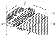
- the connecting unit 130 is a terminal of the main cable 110 that is electrically and mechanically coupled to the FFC connector formed on the PCB 10. Like the main cable 110, the connecting unit 130 is made of FFC, and all copper wires of the main cable 110 are formed. They extend from the main cable 110 in the form of sharing them.
- FIG. 2 shows an exemplary coupling diagram between the connecting portion and the FFC connector of the PCB 10.
- the connecting portion 130 is a simple structure in which a thin FFC is inserted into the PCB 10 connector 12 in comparison with a structure in which welding is performed on the PCB 10, and the like. Can achieve electrical and mechanical coupling.
- the temperature sensing unit 140 is electrically connected to the first extension part 142 and the first extension part 142 extending from the main cable 110 in a manner of sharing at least one copper wire of the main cable 110. And a ceramic thermistor 144 formed at an end portion of the first extension portion 142.
- FIG. 3 is a schematic diagram of the temperature sensing unit 140.
- the first extension portion 142 is made of FFC and the ceramic thermistor 144 may be attached to the outer surface of the battery cell, this structure is a spatial advantage of the interconnect member 100 and components required for mounting The number can be drastically reduced.
- the temperature sensing unit 140 may sense the temperature of the battery cell through a change in the current supplied from the ceramic thermistor 144 to the PCB 10 via the extension part and the connecting part 130.
- FIG 4 illustrates an interconnect member according to another embodiment of the present invention.
- the structure of the interconnection member 200 of FIG. 4 is similar to that of FIG. 1 except for the structure of the terminal portion 220.
- the bonding picture of the main cable 210 and the second extensions 224 is shown in FIG.
- the structure of the terminal unit 200 will be described together.
- Each of the terminal parts 200 is connected to a second extension part 224 and a second extension part 224 extending from the main cable 210 and connected to a voltage sensing terminal formed on a bus bar.
- 222, and the second extensions 224 are each composed of wires soldered to the copper wires of the main cable 210.
- This structure can be connected from the main cable 210 to a longer length, because the wire itself is durable, which may be advantageous when the size of the battery module is large and the distance from the main cable 210 to the battery cells is far. .
- the interconnect member has a structure similar to that of FIG. 1 or 4 except for the terminal portion, but the structure of the terminal portion is different from that of the interconnect member.
- the terminal portion 320 of the interconnect member is connected to the second extension portion and the second extension portion extending from the main cable 310 and the connection portion 330 connected to the voltage sensing terminal formed on the bus bar. ).
- the second extension part is electrically connected to copper wires of the main cable 310, and the first clamping part 324 is coupled to the main cable 310 in a clamping structure.
- the connecting portion 330 includes branching wires 332b branched at the end of the first clamping portion 324, a second clamping portion 332c coupled to the branching wires 332b in a clamping structure, and a second It extends from the clamping portion 332c, and includes a plate-shaped plate connection end 332a coupled to the connection portion 330 to the terminal for voltage sensing by soldering or laser welding.
- FIG. 7 schematically illustrates a portion of a battery module according to an embodiment of the present invention including the interconnect member of FIG. 6.
- the main cable 310 of the interconnect member is fixed to the module stack in a structure attached by an insulating film along the outer surface of the module stack, and an end of the main cable 310 is connected.
- the first clamping portion 324 of the terminal portion 320 is coupled to.
- the terminal portion 320 has branched wires 332b of the connection portion 330 branched from the first clamping portion 324 and has a plate-shaped plate connection end 332a extending from the second clamping portion 332c. Is connected to the branch wires 332b while forming the second clamping portion 332c in a clamping structure.
- connection ends 332a are respectively coupled to the voltage sensing terminal 442 of the bus bar assembly, and this coupling may be achieved by soldering, ultrasonic welding, laser welding, resistance welding, or the like, for example. Can be.
- Figure 8 schematically shows a battery module according to an embodiment of the present invention.
- the battery module 300 may include a module stack 310 in which the interconnect member 330 and battery cells are arranged laterally, and battery cells positioned at the front and rear sides of the module stack 310. And a bus bar assembly 320 for electrically connecting electrode terminals.
- the bus bar assembly 320 includes a bus bar 322 coupled to an electrode terminal of a battery cell and a main frame 326 on which bus bars 322 are fixed and mounted with a PCB 324.
- the interconnecting member 330 is fixed to the module stack 310 in a structure in which the main cable is attached by an insulating film along the outer surface of the module stack 310, and one end of the interconnect member 330 is fixed.
- the connecting portion formed at the bottom portion is connected to the PCB 324.
- the main cable is made of an extremely thin and light weight FFC, so that a separate space and a plurality of mounting members, for example, screws or bolts, rivets and coupling arms (for mounting the interconnecting members) It is possible to provide a battery module having a more compact structure, such as no arm).
Landscapes
- Chemical & Material Sciences (AREA)
- Chemical Kinetics & Catalysis (AREA)
- Electrochemistry (AREA)
- General Chemical & Material Sciences (AREA)
- Engineering & Computer Science (AREA)
- Manufacturing & Machinery (AREA)
- Physics & Mathematics (AREA)
- General Physics & Mathematics (AREA)
- Microelectronics & Electronic Packaging (AREA)
- Inorganic Chemistry (AREA)
- Battery Mounting, Suspending (AREA)
- Connection Of Batteries Or Terminals (AREA)
Priority Applications (6)
| Application Number | Priority Date | Filing Date | Title |
|---|---|---|---|
| EP17843933.7A EP3361574A4 (en) | 2016-08-24 | 2017-08-22 | INTERCONNECTING ELEMENT OCCUPYING LESS SPACE IN A BATTERY MODULE AND BATTERY MODULE COMPRISING THE SAME |
| CN202410125994.3A CN117895258A (zh) | 2016-08-24 | 2017-08-22 | 电池模块 |
| JP2018525748A JP6656373B2 (ja) | 2016-08-24 | 2017-08-22 | 電池モジュール内に占める空間が少ない相互連結部材及びこれを備える電池モジュール |
| US16/067,395 US10903469B2 (en) | 2016-08-24 | 2017-08-22 | Interconnecting member occupying less space in battery module and battery module comprising same |
| CN201780004072.5A CN108292811A (zh) | 2016-08-24 | 2017-08-22 | 在电池模块中占用较小空间的互连构件和包括互连构件的电池模块 |
| US17/126,556 US20210104803A1 (en) | 2016-08-24 | 2020-12-18 | Interconnecting member occupying less space in battery module and battery module comprising same |
Applications Claiming Priority (2)
| Application Number | Priority Date | Filing Date | Title |
|---|---|---|---|
| KR10-2016-0107886 | 2016-08-24 | ||
| KR1020160107886A KR102059612B1 (ko) | 2016-08-24 | 2016-08-24 | 전지모듈 내에서 공간을 적게 점유하는 상호 연결 부재 및 이를 포함하는 전지모듈 |
Related Child Applications (2)
| Application Number | Title | Priority Date | Filing Date |
|---|---|---|---|
| US16/067,395 A-371-Of-International US10903469B2 (en) | 2016-08-24 | 2017-08-22 | Interconnecting member occupying less space in battery module and battery module comprising same |
| US17/126,556 Continuation US20210104803A1 (en) | 2016-08-24 | 2020-12-18 | Interconnecting member occupying less space in battery module and battery module comprising same |
Publications (1)
| Publication Number | Publication Date |
|---|---|
| WO2018038513A1 true WO2018038513A1 (ko) | 2018-03-01 |
Family
ID=61245161
Family Applications (1)
| Application Number | Title | Priority Date | Filing Date |
|---|---|---|---|
| PCT/KR2017/009169 WO2018038513A1 (ko) | 2016-08-24 | 2017-08-22 | 전지모듈 내에서 공간을 적게 점유하는 상호 연결 부재 및 이를 포함하는 전지모듈 |
Country Status (6)
| Country | Link |
|---|---|
| US (2) | US10903469B2 (ja) |
| EP (1) | EP3361574A4 (ja) |
| JP (1) | JP6656373B2 (ja) |
| KR (1) | KR102059612B1 (ja) |
| CN (2) | CN108292811A (ja) |
| WO (1) | WO2018038513A1 (ja) |
Cited By (4)
| Publication number | Priority date | Publication date | Assignee | Title |
|---|---|---|---|---|
| CN111430650A (zh) * | 2019-11-22 | 2020-07-17 | 蜂巢能源科技有限公司 | 电池包和车辆 |
| US20210273267A1 (en) * | 2019-06-18 | 2021-09-02 | Lg Chem, Ltd. | Battery Module and Battery Pack Including the Same |
| JP2021525436A (ja) * | 2018-10-10 | 2021-09-24 | エルジー・ケム・リミテッド | 空間節約型icb組立体を適用したバッテリーモジュール |
| CN114824673A (zh) * | 2021-01-27 | 2022-07-29 | 莫仕连接器(成都)有限公司 | 电池连接模块 |
Families Citing this family (15)
| Publication number | Priority date | Publication date | Assignee | Title |
|---|---|---|---|---|
| GB201707194D0 (en) * | 2017-05-05 | 2017-06-21 | Nicoventures Holdings Ltd | Electronic aerosol provision system |
| DE102018213911A1 (de) * | 2018-08-17 | 2020-02-20 | Robert Bosch Gmbh | Zellkontaktierungssystem für eine modular aufgebaute Batterie |
| CN113728506A (zh) * | 2019-02-22 | 2021-11-30 | 帝威尼梅吉克股份公司 | 电池连接装置及其方法 |
| KR20210011881A (ko) | 2019-07-23 | 2021-02-02 | 에스케이이노베이션 주식회사 | 센싱 어셈블리, 센싱 어셈블리의 제조방법 및 센싱 어셈블리를 포함하는 배터리 모듈 |
| US20210028513A1 (en) | 2019-07-23 | 2021-01-28 | Sk Innovation Co., Ltd. | Sensing Assembly, Manufacturing Method for Thereof and Battery Module Comprising the Same |
| EP3886207A1 (en) * | 2020-03-27 | 2021-09-29 | TE Connectivity Germany GmbH | Cell connecting system for a vehicle battery module and method for manufacturing the cell system |
| KR20220012033A (ko) * | 2020-07-22 | 2022-02-03 | 주식회사 엘지에너지솔루션 | 전극 리드와 전압 센싱부재 간의 연결을 단순화한 배터리 모듈 및 이를 포함하는 배터리 팩 |
| CN114069061A (zh) * | 2020-08-05 | 2022-02-18 | 上海汽车集团股份有限公司 | 车辆、电池模组和用于电池模组的采样设备 |
| KR20220036131A (ko) | 2020-09-15 | 2022-03-22 | 에스케이온 주식회사 | 센싱 어셈블리 및 배터리 모듈 |
| JP7239542B2 (ja) * | 2020-11-16 | 2023-03-14 | 矢崎総業株式会社 | 導電モジュール |
| CN112599937B (zh) * | 2020-12-15 | 2023-10-31 | 湖北亿纬动力有限公司 | 电池采集方法及电池采集系统 |
| CN112615073B (zh) * | 2020-12-31 | 2023-05-26 | 上海捷新动力电池系统有限公司 | 一种动力电池包内ffc温度采样结构及其工艺流程 |
| EP4254623A1 (en) * | 2022-03-30 | 2023-10-04 | Samsung SDI Co., Ltd. | A battery pack, an electric vehicle and a method for assembling a battery pack |
| CN114976521A (zh) * | 2022-07-18 | 2022-08-30 | 上海兰钧新能源科技有限公司 | 电池采样组件和电池包 |
| KR20240042893A (ko) * | 2022-09-26 | 2024-04-02 | 주식회사 엘지에너지솔루션 | 와이어 집합체로 구성되는 버스바 본체를 포함하는 버스바 어셈블리 |
Citations (5)
| Publication number | Priority date | Publication date | Assignee | Title |
|---|---|---|---|---|
| JPH07115219A (ja) * | 1993-10-19 | 1995-05-02 | Yazaki Corp | 太陽電池 |
| JP2001250520A (ja) * | 2000-03-02 | 2001-09-14 | Toshiba Battery Co Ltd | 電池パックおよび電子機器 |
| JP2002042903A (ja) * | 2000-07-26 | 2002-02-08 | Toyota Motor Corp | 電源装置 |
| KR20090095949A (ko) * | 2008-03-07 | 2009-09-10 | 주식회사 엘지화학 | 전지모듈의 전극단자 접속부재 |
| KR20130125334A (ko) * | 2012-05-08 | 2013-11-18 | 삼성에스디아이 주식회사 | 배터리 팩 |
Family Cites Families (18)
| Publication number | Priority date | Publication date | Assignee | Title |
|---|---|---|---|---|
| JPS545781U (ja) * | 1977-06-15 | 1979-01-16 | ||
| EP1071147A1 (en) | 1999-07-19 | 2001-01-24 | Toshiba Battery Co., Ltd. | Battery pack |
| JP2001229741A (ja) * | 2000-02-16 | 2001-08-24 | Nippon Mektron Ltd | 配線材料及びその製造法並びにそれを用いた配線部品 |
| JP5213629B2 (ja) * | 2008-03-07 | 2013-06-19 | スリーエム イノベイティブ プロパティズ カンパニー | 基板用電線接続構造体及び中継接続体の製造方法並びに中継接続体の固定方法 |
| FR2967308A1 (fr) | 2010-11-06 | 2012-05-11 | Johnson Controls Tech Co | Dispositif de raccordement electrique flexible entre un composant electrique et une carte imprimee, systeme, et procede de montage d'un systeme. |
| JP5646046B2 (ja) * | 2011-04-04 | 2014-12-24 | 日立オートモティブシステムズ株式会社 | 蓄電モジュール |
| CN102956934B (zh) * | 2011-08-17 | 2015-05-13 | 比亚迪股份有限公司 | 一种电池模组 |
| JP6278957B2 (ja) * | 2012-05-14 | 2018-02-14 | 深▲セン▼市敏▲傑▼▲電▼子科技有限公司 | 表面温度計測の温度センサー |
| CN102735367A (zh) * | 2012-07-09 | 2012-10-17 | 深圳市敏杰电子科技有限公司 | 表面测温温度传感器 |
| JP6257889B2 (ja) * | 2012-10-23 | 2018-01-10 | 日本メクトロン株式会社 | バスバー付きフレキシブルプリント配線板およびその製造方法、並びにバッテリシステム |
| JP2014143079A (ja) | 2013-01-24 | 2014-08-07 | Hitachi Metals Ltd | フラット配線材及びその製造方法 |
| KR101720614B1 (ko) | 2013-08-30 | 2017-03-28 | 삼성에스디아이 주식회사 | 배터리 팩 |
| JP2015118731A (ja) | 2013-12-16 | 2015-06-25 | 日立金属株式会社 | 配線材、二次電池装置、電子機器、及び配線材の製造方法 |
| WO2015197319A1 (de) | 2014-06-26 | 2015-12-30 | Robert Bosch Gmbh | Übertragungsvorrichtung zum übertragen von elektrischen signalen von wenigstens einer galvanischen zelle an zumindest eine elektronische auswerteeinheit |
| CN204216124U (zh) | 2014-09-29 | 2015-03-18 | 东莞市德尔能新能源科技有限公司 | 具有弯折fpc软板的内置电池 |
| JP2016090286A (ja) * | 2014-10-30 | 2016-05-23 | 矢崎総業株式会社 | 温度検出体の取付構造 |
| US10396405B2 (en) | 2014-11-10 | 2019-08-27 | Te Connectivity Corporation | Bus bar for a battery connector system |
| CN204788709U (zh) | 2014-12-17 | 2015-11-18 | 深圳市敏杰电子科技有限公司 | 薄膜型温度传感器 |
-
2016
- 2016-08-24 KR KR1020160107886A patent/KR102059612B1/ko active IP Right Grant
-
2017
- 2017-08-22 CN CN201780004072.5A patent/CN108292811A/zh active Pending
- 2017-08-22 WO PCT/KR2017/009169 patent/WO2018038513A1/ko active Application Filing
- 2017-08-22 EP EP17843933.7A patent/EP3361574A4/en active Pending
- 2017-08-22 CN CN202410125994.3A patent/CN117895258A/zh active Pending
- 2017-08-22 US US16/067,395 patent/US10903469B2/en active Active
- 2017-08-22 JP JP2018525748A patent/JP6656373B2/ja active Active
-
2020
- 2020-12-18 US US17/126,556 patent/US20210104803A1/en active Pending
Patent Citations (5)
| Publication number | Priority date | Publication date | Assignee | Title |
|---|---|---|---|---|
| JPH07115219A (ja) * | 1993-10-19 | 1995-05-02 | Yazaki Corp | 太陽電池 |
| JP2001250520A (ja) * | 2000-03-02 | 2001-09-14 | Toshiba Battery Co Ltd | 電池パックおよび電子機器 |
| JP2002042903A (ja) * | 2000-07-26 | 2002-02-08 | Toyota Motor Corp | 電源装置 |
| KR20090095949A (ko) * | 2008-03-07 | 2009-09-10 | 주식회사 엘지화학 | 전지모듈의 전극단자 접속부재 |
| KR20130125334A (ko) * | 2012-05-08 | 2013-11-18 | 삼성에스디아이 주식회사 | 배터리 팩 |
Non-Patent Citations (1)
| Title |
|---|
| See also references of EP3361574A4 * |
Cited By (6)
| Publication number | Priority date | Publication date | Assignee | Title |
|---|---|---|---|---|
| JP2021525436A (ja) * | 2018-10-10 | 2021-09-24 | エルジー・ケム・リミテッド | 空間節約型icb組立体を適用したバッテリーモジュール |
| JP7119126B2 (ja) | 2018-10-10 | 2022-08-16 | エルジー エナジー ソリューション リミテッド | 空間節約型icb組立体を適用したバッテリーモジュール |
| US20210273267A1 (en) * | 2019-06-18 | 2021-09-02 | Lg Chem, Ltd. | Battery Module and Battery Pack Including the Same |
| CN111430650A (zh) * | 2019-11-22 | 2020-07-17 | 蜂巢能源科技有限公司 | 电池包和车辆 |
| CN111430650B (zh) * | 2019-11-22 | 2022-02-25 | 蜂巢能源科技有限公司 | 电池包和车辆 |
| CN114824673A (zh) * | 2021-01-27 | 2022-07-29 | 莫仕连接器(成都)有限公司 | 电池连接模块 |
Also Published As
| Publication number | Publication date |
|---|---|
| US20190020012A1 (en) | 2019-01-17 |
| JP2018538669A (ja) | 2018-12-27 |
| CN108292811A (zh) | 2018-07-17 |
| EP3361574A4 (en) | 2019-01-16 |
| KR20180022445A (ko) | 2018-03-06 |
| KR102059612B1 (ko) | 2019-12-26 |
| EP3361574A1 (en) | 2018-08-15 |
| US10903469B2 (en) | 2021-01-26 |
| CN117895258A (zh) | 2024-04-16 |
| US20210104803A1 (en) | 2021-04-08 |
| JP6656373B2 (ja) | 2020-03-04 |
Similar Documents
| Publication | Publication Date | Title |
|---|---|---|
| WO2018038513A1 (ko) | 전지모듈 내에서 공간을 적게 점유하는 상호 연결 부재 및 이를 포함하는 전지모듈 | |
| WO2011152668A2 (en) | Battery module having novel structure | |
| WO2018066797A1 (ko) | 배터리 모듈, 이러한 배터리 모듈을 포함하는 배터리 팩 및 이러한 배터리 팩을 포함하는 자동차 | |
| WO2014073808A1 (ko) | 버스 바 어셈블리를 포함하는 전지모듈 및 이를 포함하는 전지팩 | |
| WO2012070782A2 (ko) | 콤팩트한 구조의 전지팩 | |
| WO2012023754A1 (ko) | 전압 검출 어셈블리 및 이를 포함하는 전지모듈 | |
| WO2009110771A2 (ko) | 전지모듈의 전극단자 접속부재 | |
| WO2014148791A1 (ko) | 전압 검출부재 및 이를 포함하는 전지모듈 | |
| WO2019107734A1 (ko) | 셀 조립체에 대한 초기 가압력 강화 구조를 갖는 배터리 모듈 및 그 제조방법 | |
| WO2019074211A1 (ko) | 전극 리드 접합용 버스바 조립체 및 이를 포함하는 배터리 모듈 | |
| WO2011126315A2 (ko) | 신규한 구조의 센싱부재를 포함하는 전지모듈 | |
| WO2017095003A1 (ko) | 그립핑부가 구비되어 있는 카트리지를 포함하고 있는 전지모듈 | |
| WO2015152638A1 (ko) | 언더 베이스 바를 포함하는 배터리 모듈 어레이 | |
| WO2019172545A1 (ko) | 배터리 모듈, 이러한 배터리 모듈을 포함하는 배터리 팩 및 이러한 배터리 팩을 포함하는 자동차 | |
| WO2012033313A2 (ko) | 고출력 대용량의 전지팩 | |
| WO2017014449A1 (ko) | 단자 플레이트 및 bms가 직접 연결된 구조의 전지모듈 | |
| WO2019074206A1 (ko) | 전극 리드 접합용 버스바 조립체 및 이를 포함하는 배터리 모듈 | |
| WO2015133760A1 (ko) | 리셉터클 구조의 전압 센싱부재를 포함하는 전지모듈 | |
| WO2018105957A1 (ko) | 착탈식 전지 컴포넌트 캐리어, 착탈식 전지 컴포넌트 캐리어를 포함하는 전지 시스템 및 전지 시스템을 포함한 자동차 | |
| WO2018230819A1 (ko) | 배터리 모듈, 이러한 배터리 모듈을 포함하는 배터리 팩 및 이러한 배터리 팩을 포함하는 자동차 | |
| WO2018080181A1 (ko) | 인쇄 회로 기판용 커넥터 및 인쇄 회로 기판과 커넥터를 포함한 전지 시스템 | |
| WO2021256673A1 (ko) | 버스바 연결용 솔더 핀을 구비한 배터리 모듈 및 이를 포함하는 배터리 팩 | |
| WO2020022735A1 (ko) | 버스바 조립체 | |
| WO2017213384A1 (ko) | 센싱 와이어 하네스의 접속 구조가 개선된 배터리 모듈 및 그 조립방법 | |
| WO2018080177A1 (ko) | 전지 시스템 용 버스바 및 이를 포함하는 전지 시스템 |
Legal Events
| Date | Code | Title | Description |
|---|---|---|---|
| WWE | Wipo information: entry into national phase |
Ref document number: 2017843933 Country of ref document: EP |
|
| WWE | Wipo information: entry into national phase |
Ref document number: 2018525748 Country of ref document: JP |
|
| NENP | Non-entry into the national phase |
Ref country code: DE |