WO2018037815A1 - 車両制御装置 - Google Patents
車両制御装置 Download PDFInfo
- Publication number
- WO2018037815A1 WO2018037815A1 PCT/JP2017/026978 JP2017026978W WO2018037815A1 WO 2018037815 A1 WO2018037815 A1 WO 2018037815A1 JP 2017026978 W JP2017026978 W JP 2017026978W WO 2018037815 A1 WO2018037815 A1 WO 2018037815A1
- Authority
- WO
- WIPO (PCT)
- Prior art keywords
- vehicle
- target
- information
- performance
- control device
- Prior art date
- Legal status (The legal status is an assumption and is not a legal conclusion. Google has not performed a legal analysis and makes no representation as to the accuracy of the status listed.)
- Ceased
Links
Images


Classifications
-
- B—PERFORMING OPERATIONS; TRANSPORTING
- B60—VEHICLES IN GENERAL
- B60W—CONJOINT CONTROL OF VEHICLE SUB-UNITS OF DIFFERENT TYPE OR DIFFERENT FUNCTION; CONTROL SYSTEMS SPECIALLY ADAPTED FOR HYBRID VEHICLES; ROAD VEHICLE DRIVE CONTROL SYSTEMS FOR PURPOSES NOT RELATED TO THE CONTROL OF A PARTICULAR SUB-UNIT
- B60W30/00—Purposes of road vehicle drive control systems not related to the control of a particular sub-unit, e.g. of systems using conjoint control of vehicle sub-units
- B60W30/18—Propelling the vehicle
- B60W30/188—Controlling power parameters of the driveline, e.g. determining the required power
-
- B—PERFORMING OPERATIONS; TRANSPORTING
- B60—VEHICLES IN GENERAL
- B60W—CONJOINT CONTROL OF VEHICLE SUB-UNITS OF DIFFERENT TYPE OR DIFFERENT FUNCTION; CONTROL SYSTEMS SPECIALLY ADAPTED FOR HYBRID VEHICLES; ROAD VEHICLE DRIVE CONTROL SYSTEMS FOR PURPOSES NOT RELATED TO THE CONTROL OF A PARTICULAR SUB-UNIT
- B60W10/00—Conjoint control of vehicle sub-units of different type or different function
- B60W10/10—Conjoint control of vehicle sub-units of different type or different function including control of change-speed gearings
- B60W10/101—Infinitely variable gearings
- B60W10/107—Infinitely variable gearings with endless flexible members
-
- B—PERFORMING OPERATIONS; TRANSPORTING
- B60—VEHICLES IN GENERAL
- B60W—CONJOINT CONTROL OF VEHICLE SUB-UNITS OF DIFFERENT TYPE OR DIFFERENT FUNCTION; CONTROL SYSTEMS SPECIALLY ADAPTED FOR HYBRID VEHICLES; ROAD VEHICLE DRIVE CONTROL SYSTEMS FOR PURPOSES NOT RELATED TO THE CONTROL OF A PARTICULAR SUB-UNIT
- B60W10/00—Conjoint control of vehicle sub-units of different type or different function
- B60W10/04—Conjoint control of vehicle sub-units of different type or different function including control of propulsion units
- B60W10/06—Conjoint control of vehicle sub-units of different type or different function including control of propulsion units including control of combustion engines
-
- B—PERFORMING OPERATIONS; TRANSPORTING
- B60—VEHICLES IN GENERAL
- B60W—CONJOINT CONTROL OF VEHICLE SUB-UNITS OF DIFFERENT TYPE OR DIFFERENT FUNCTION; CONTROL SYSTEMS SPECIALLY ADAPTED FOR HYBRID VEHICLES; ROAD VEHICLE DRIVE CONTROL SYSTEMS FOR PURPOSES NOT RELATED TO THE CONTROL OF A PARTICULAR SUB-UNIT
- B60W10/00—Conjoint control of vehicle sub-units of different type or different function
- B60W10/10—Conjoint control of vehicle sub-units of different type or different function including control of change-speed gearings
- B60W10/101—Infinitely variable gearings
-
- B—PERFORMING OPERATIONS; TRANSPORTING
- B60—VEHICLES IN GENERAL
- B60W—CONJOINT CONTROL OF VEHICLE SUB-UNITS OF DIFFERENT TYPE OR DIFFERENT FUNCTION; CONTROL SYSTEMS SPECIALLY ADAPTED FOR HYBRID VEHICLES; ROAD VEHICLE DRIVE CONTROL SYSTEMS FOR PURPOSES NOT RELATED TO THE CONTROL OF A PARTICULAR SUB-UNIT
- B60W10/00—Conjoint control of vehicle sub-units of different type or different function
- B60W10/10—Conjoint control of vehicle sub-units of different type or different function including control of change-speed gearings
- B60W10/11—Stepped gearings
-
- B—PERFORMING OPERATIONS; TRANSPORTING
- B60—VEHICLES IN GENERAL
- B60W—CONJOINT CONTROL OF VEHICLE SUB-UNITS OF DIFFERENT TYPE OR DIFFERENT FUNCTION; CONTROL SYSTEMS SPECIALLY ADAPTED FOR HYBRID VEHICLES; ROAD VEHICLE DRIVE CONTROL SYSTEMS FOR PURPOSES NOT RELATED TO THE CONTROL OF A PARTICULAR SUB-UNIT
- B60W50/00—Details of control systems for road vehicle drive control not related to the control of a particular sub-unit, e.g. process diagnostic or vehicle driver interfaces
- B60W50/02—Ensuring safety in case of control system failures, e.g. by diagnosing, circumventing or fixing failures
- B60W50/032—Fixing failures by repairing failed parts, e.g. loosening a sticking valve
-
- B—PERFORMING OPERATIONS; TRANSPORTING
- B60—VEHICLES IN GENERAL
- B60W—CONJOINT CONTROL OF VEHICLE SUB-UNITS OF DIFFERENT TYPE OR DIFFERENT FUNCTION; CONTROL SYSTEMS SPECIALLY ADAPTED FOR HYBRID VEHICLES; ROAD VEHICLE DRIVE CONTROL SYSTEMS FOR PURPOSES NOT RELATED TO THE CONTROL OF A PARTICULAR SUB-UNIT
- B60W50/00—Details of control systems for road vehicle drive control not related to the control of a particular sub-unit, e.g. process diagnostic or vehicle driver interfaces
- B60W50/04—Monitoring the functioning of the control system
-
- F—MECHANICAL ENGINEERING; LIGHTING; HEATING; WEAPONS; BLASTING
- F16—ENGINEERING ELEMENTS AND UNITS; GENERAL MEASURES FOR PRODUCING AND MAINTAINING EFFECTIVE FUNCTIONING OF MACHINES OR INSTALLATIONS; THERMAL INSULATION IN GENERAL
- F16H—GEARING
- F16H59/00—Control inputs to control units of change-speed- or reversing-gearings for conveying rotary motion
- F16H59/60—Inputs being a function of ambient conditions
- F16H59/66—Road conditions, e.g. slope, slippery
-
- F—MECHANICAL ENGINEERING; LIGHTING; HEATING; WEAPONS; BLASTING
- F16—ENGINEERING ELEMENTS AND UNITS; GENERAL MEASURES FOR PRODUCING AND MAINTAINING EFFECTIVE FUNCTIONING OF MACHINES OR INSTALLATIONS; THERMAL INSULATION IN GENERAL
- F16H—GEARING
- F16H59/00—Control inputs to control units of change-speed- or reversing-gearings for conveying rotary motion
- F16H59/68—Inputs being a function of gearing status
- F16H59/70—Inputs being a function of gearing status dependent on the ratio established
-
- F—MECHANICAL ENGINEERING; LIGHTING; HEATING; WEAPONS; BLASTING
- F16—ENGINEERING ELEMENTS AND UNITS; GENERAL MEASURES FOR PRODUCING AND MAINTAINING EFFECTIVE FUNCTIONING OF MACHINES OR INSTALLATIONS; THERMAL INSULATION IN GENERAL
- F16H—GEARING
- F16H61/00—Control functions within control units of change-speed- or reversing-gearings for conveying rotary motion ; Control of exclusively fluid gearing, friction gearing, gearings with endless flexible members or other particular types of gearing
- F16H61/02—Control functions within control units of change-speed- or reversing-gearings for conveying rotary motion ; Control of exclusively fluid gearing, friction gearing, gearings with endless flexible members or other particular types of gearing characterised by the signals used
-
- B—PERFORMING OPERATIONS; TRANSPORTING
- B60—VEHICLES IN GENERAL
- B60W—CONJOINT CONTROL OF VEHICLE SUB-UNITS OF DIFFERENT TYPE OR DIFFERENT FUNCTION; CONTROL SYSTEMS SPECIALLY ADAPTED FOR HYBRID VEHICLES; ROAD VEHICLE DRIVE CONTROL SYSTEMS FOR PURPOSES NOT RELATED TO THE CONTROL OF A PARTICULAR SUB-UNIT
- B60W2510/00—Input parameters relating to a particular sub-units
- B60W2510/10—Change speed gearings
- B60W2510/1005—Transmission ratio engaged
-
- B—PERFORMING OPERATIONS; TRANSPORTING
- B60—VEHICLES IN GENERAL
- B60W—CONJOINT CONTROL OF VEHICLE SUB-UNITS OF DIFFERENT TYPE OR DIFFERENT FUNCTION; CONTROL SYSTEMS SPECIALLY ADAPTED FOR HYBRID VEHICLES; ROAD VEHICLE DRIVE CONTROL SYSTEMS FOR PURPOSES NOT RELATED TO THE CONTROL OF A PARTICULAR SUB-UNIT
- B60W2540/00—Input parameters relating to occupants
- B60W2540/10—Accelerator pedal position
-
- B—PERFORMING OPERATIONS; TRANSPORTING
- B60—VEHICLES IN GENERAL
- B60W—CONJOINT CONTROL OF VEHICLE SUB-UNITS OF DIFFERENT TYPE OR DIFFERENT FUNCTION; CONTROL SYSTEMS SPECIALLY ADAPTED FOR HYBRID VEHICLES; ROAD VEHICLE DRIVE CONTROL SYSTEMS FOR PURPOSES NOT RELATED TO THE CONTROL OF A PARTICULAR SUB-UNIT
- B60W2710/00—Output or target parameters relating to a particular sub-units
- B60W2710/06—Combustion engines, Gas turbines
- B60W2710/0666—Engine torque
-
- B—PERFORMING OPERATIONS; TRANSPORTING
- B60—VEHICLES IN GENERAL
- B60W—CONJOINT CONTROL OF VEHICLE SUB-UNITS OF DIFFERENT TYPE OR DIFFERENT FUNCTION; CONTROL SYSTEMS SPECIALLY ADAPTED FOR HYBRID VEHICLES; ROAD VEHICLE DRIVE CONTROL SYSTEMS FOR PURPOSES NOT RELATED TO THE CONTROL OF A PARTICULAR SUB-UNIT
- B60W2710/00—Output or target parameters relating to a particular sub-units
- B60W2710/10—Change speed gearings
- B60W2710/1005—Transmission ratio engaged
-
- F—MECHANICAL ENGINEERING; LIGHTING; HEATING; WEAPONS; BLASTING
- F16—ENGINEERING ELEMENTS AND UNITS; GENERAL MEASURES FOR PRODUCING AND MAINTAINING EFFECTIVE FUNCTIONING OF MACHINES OR INSTALLATIONS; THERMAL INSULATION IN GENERAL
- F16H—GEARING
- F16H59/00—Control inputs to control units of change-speed- or reversing-gearings for conveying rotary motion
- F16H59/68—Inputs being a function of gearing status
- F16H2059/6823—Sensing neutral state of the transmission
-
- Y—GENERAL TAGGING OF NEW TECHNOLOGICAL DEVELOPMENTS; GENERAL TAGGING OF CROSS-SECTIONAL TECHNOLOGIES SPANNING OVER SEVERAL SECTIONS OF THE IPC; TECHNICAL SUBJECTS COVERED BY FORMER USPC CROSS-REFERENCE ART COLLECTIONS [XRACs] AND DIGESTS
- Y02—TECHNOLOGIES OR APPLICATIONS FOR MITIGATION OR ADAPTATION AGAINST CLIMATE CHANGE
- Y02T—CLIMATE CHANGE MITIGATION TECHNOLOGIES RELATED TO TRANSPORTATION
- Y02T10/00—Road transport of goods or passengers
- Y02T10/60—Other road transportation technologies with climate change mitigation effect
- Y02T10/62—Hybrid vehicles
Definitions
- the present invention relates to a vehicle control device for stabilizing vehicle behavior (performance).
- the actuator ECU controls the actuator based on a drive command from an ECU that controls the vehicle motion (herein, the vehicle overall ECU).
- the vehicle control ECU issues a drive command to the engine control ECU, so that the shift control ECU performs shift control based on torque information calculated by the engine control ECU, thereby realizing automatic driving. That is, even in the automatic driving system, the engine is controlled automatically, specifically the throttle, and there is an automatic driving system that is not automated on the automatic transmission side.
- correction techniques when the power characteristics change due to deterioration of the engine or automatic transmission over time.
- the clutch switching timing is accurately detected from information such as the rate of change of the output shaft speed and power characteristics in order to reduce shift shock.
- Patent Document 1 uses a motor with relatively little deterioration over time to monitor torque, and grasps a change in engine power characteristics, so that torque when shifting from engine running to motor running is known. It is intended to suppress the level difference, and when switching the drive, it matches the inferior performance, leading to a decrease in performance as a vehicle.
- Patent Document 2 is a technique for suppressing a shift shock at the time of a coast downshift with rotation synchronous control, and it is difficult to say that the driving scenes at the time of automatic driving are covered.
- rate of change of the input shaft torque is changed according to the change with time of ATF)
- only the oil temperature is defined as the change with time, and the change in viscosity during aging is not taken into consideration.
- the present invention has been made in view of the above-described problems, and the object of the present invention is to provide a vehicle component even when the power generation device or the power transmission device changes its power characteristics due to factors such as aging during automatic operation. It is to realize a vehicle control device that detects deterioration and corrects a drive instruction to a power transmission device and can stabilize vehicle behavior (performance) for a long period of time.
- the present invention is configured as follows.
- a target drive torque determination unit that determines a target drive torque of a drive torque generation mechanism that drives the vehicle based on control content generated in advance and controls the operation of the drive torque generation mechanism; and the target drive A performance change information acquisition unit for acquiring information on a change in performance of a vehicle component including at least one of a transmission that determines a target speed ratio based on torque and the drive torque generation mechanism, and on the basis of the target drive torque A target gear ratio correction unit that corrects the determined target gear ratio according to the information related to the change in performance.
- the present invention even when the power characteristics of the power generation device and the power transmission device change due to factors such as aging during automatic driving, the deterioration of the vehicle components is detected and a drive instruction to the power transmission device is issued. It is possible to realize a vehicle control apparatus that can correct the vehicle behavior (performance) for a long period of time.
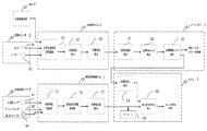
- FIG. 1 is a system configuration diagram excerpting a powertrain system in automatic operation according to an embodiment of the present invention.
- FIG. 7 is an example different from the present invention, and an example of a system configuration excerpting a powertrain system in automatic operation is shown in FIG. It is the figure shown in order to compare with invention.
- the vehicle integrated ECU 12 acquires environmental information and own vehicle surrounding map information (road gradient, road curvature radius) from a radar, a camera, etc., and calculates a target trajectory. Subsequently, the vehicle integrated ECU 12 calculates a target vehicle speed from the target track, and transmits information to the engine ECU 13 via the gateway ECU 11.
- map information road gradient, road curvature radius
- the engine ECU 13 calculates a target acceleration from the current actual vehicle speed and the target vehicle speed, and determines a target engine torque corresponding to the target acceleration.
- the engine ECU 13 controls the engine 6 to obtain the target engine torque, and simultaneously transmits the estimated engine torque and target drive torque information to be transmitted to the road surface to the transmission ECU 15 (ATCU).
- ATCU transmission ECU 15
- the engine ECU 3 not only the engine ECU 3 but also the ATCU 5 is added to the connection destination of the vehicle integrated ECU 2 via the gateway ECU 1. Further, a signal from the vehicle behavior sensor 4 is also supplied to the vehicle integrated ECU 2 in order to detect the vehicle behavior due to aging of the component parts.
- the vehicle behavior sensor 4 is an acceleration sensor 41, a yaw rate sensor 42, and a vehicle speed sensor 43.
- the performance change information acquisition ECU vehicle attitude control unit
- Aging deterioration can be detected.
- the present invention corrects the actuator command value on the side of the transmission 16 which is the final stage of the powertrain system, and corrects the aging deterioration with the transmission 16 having a quick response. It has the effect of stabilizing the behavior.
- the engine 6 that is a vehicle driving torque generation mechanism is feedback-controlled by the engine ECU 3 that is a target driving torque determination unit based on the determined target driving torque, and the transmission 16 Based on the drive torque, feedforward control is performed by the ATCU 5 which is a target gear ratio correction unit.
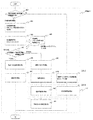
- FIG. 2 is a diagram showing a control flow from the vehicle behavior sensor to the driving torque output from the automatic transmission 16.
- the vehicle integrated ECU 2 uses the map information from the MPU 9 and the information from the sensor 8 of the recognition system including the camera 81 and the radar 82 to allow the vehicle position peripheral space recognition unit 21 to perform space recognition.
- the target trajectory calculation unit 22 calculates the target trajectory.
- the target vehicle speed calculation unit 23 calculates a target vehicle speed that can travel on the target track, and transmits information to the target acceleration calculation unit 31 of the engine ECU 3.
- the target acceleration calculation unit 31 is also supplied with actual vehicle speed information, and the target acceleration calculation unit 31 calculates the target acceleration from the current actual vehicle speed and the target vehicle speed.
- the calculated target acceleration is supplied to the target engine torque calculation unit 32, and a target engine torque corresponding to the target acceleration is determined.
- the target drive torque calculation unit 33 performs fuel supply to the engine, ignition timing, and throttle control to obtain the target engine torque, and at the same time, the target gear ratio calculation unit 54 of the ATCU 5 should transmit the estimated engine torque and the road surface. Target drive torque information is transmitted.
- the vehicle behavior detection unit 71 of the vehicle attitude control ECU 7 detects information (acceleration, yaw rate, vehicle speed) from the vehicle behavior sensor 4 and acquires performance change information based on the detected vehicle behavior information.
- the unit 72 detects aged deterioration of the powertrain system. The detection of aging deterioration of the powertrain system will be described later.
- the target correction amount calculation unit 73 calculates a target correction amount for the transmission 16 from the rate of change in vehicle behavior, and transmits information to the post-correction target gear ratio calculation unit 55 of the ATCU 5.
- the corrected target transmission gear ratio calculation unit 55 of the ATCU 5 calculates the corrected target transmission gear ratio from the target drive torque information from the engine ECU 3 and the target correction amount from the vehicle attitude control ECU 7, and the actuator in the transmission 16 is operated. By controlling (solenoid drive control), drive torque is output.
- the above-described detection of aged deterioration of the powertrain system by the performance change information acquisition unit 72 is performed under specific conditions and fed back to the corrected target gear ratio.
- the target correction amount calculated by the target correction amount calculation unit 73 is stored in the nonvolatile memory 56.
- the vehicle attitude control ECU 7 is an ECU separate from the vehicle integrated ECU 2, but the vehicle attitude control ECU 7 can be included in the vehicle integrated ECU 2.
- FIG. 3 is a control flow of automatic operation aging deterioration correction control in one embodiment of the present invention.
- Step S401 in FIG. 3 is a step in which the vehicle integrated ECU 2 determines whether or not the current traveling environment is an execution condition of the aging deterioration correction control based on the map information while the vehicle is traveling by automatic driving.
- vehicle information DB vehicle information database
- the DB requires a large amount of data such as vehicle speed, throttle opening, gear ratio, road gradient, and vehicle behavior. For this reason, if the aging deterioration correction control is always performed, the processing load on the CPU and the memory consumption amount increase, and there is a concern that a shift control that should be originally performed may be delayed. That is, in order to reduce the processing load on the CPU and the memory consumption, it is necessary to determine in advance the timing for performing the aging deterioration correction control. For this reason, the road gradient and the road curvature radius are acquired from the map information, and the aged deterioration correction control is performed only when the acquired road gradient and road curvature radius satisfy a predetermined condition.
- step S401 If it is determined in step S401 that the aging deterioration correction control can be performed, the process proceeds to step S402.
- Step S402 is a step of acquiring vehicle environment information when it is determined that aging deterioration correction control can be performed. Specifically, the vehicle speed, the throttle opening, the gear ratio, the road surface gradient, the radius of curvature (R), and the like are acquired. The purpose of the acquisition is the problem of the timing of acquisition or aged deterioration determination when compared with the vehicle information DB. Therefore, when there is a difference in any of the information, the determination of the aging deterioration is stopped or the target correction amount is calculated based on the difference information.
- Step S403 is a step of acquiring vehicle behavior information when it is determined that the aging deterioration correction control can be performed. For the purpose, as in step S402, when comparing with the vehicle information DB, if there is a difference in any information due to the timing of acquisition or aging deterioration determination, the aging deterioration determination is canceled, or This is because the target correction amount is calculated based on the difference information.
- step S404 data such as vehicle speed, throttle opening, gear ratio, road surface gradient, vehicle behavior, and the like when the conditions for execution of aging deterioration correction control are satisfied are compiled into a database.
- the vehicle information DB is configured to create a database of vehicle behavior with respect to the amount of actuator operation up to the information acquisition timing in addition to the vehicle information at an arbitrarily acquired timing, and to confirm the change over time in the power characteristics of the constituent engines.
- the object is to determine whether the change in the power characteristics of the constituent engines is due to deterioration over time or due to failure.
- Step S405 is a step of performing aged deterioration determination when the execution conditions for the aged deterioration correction control are satisfied.
- the current vehicle behavior is compared with the vehicle information DB to determine deterioration, if it is determined that there is no deterioration over time in this step, it can be determined that the power characteristics have been improved by replacement of parts or replacement of consumables.
- step S406 the notification of the deterioration state to the driver is canceled.
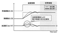
- FIG. 4 is an explanatory diagram of the principle of detecting deterioration of power performance.
- the target driving force is raised, after the transition region has elapsed, the steady driving region is reached and the actual driving force and acceleration are stabilized.
- the fluctuation in the transient region is different from the reference fluctuation in the case where the deterioration is not deteriorated (thin solid line) and the fluctuation in the case where it is deteriorated (thick solid line).
- the reference fluctuation in the transient region of the actual driving force and acceleration when the power performance is not deteriorated is stored in the vehicle information DB, and compared with the detected fluctuation in the transient period of the actual driving force and acceleration.
- deterioration determination can be performed.
- Acceleration can be calculated by the following equation (1), and driving force can be calculated by the following equation (2).
- step S406 After canceling the notification of the deterioration state to the driver in step S406, the process proceeds to step S407, and the target correction amount stored in the nonvolatile memory 56 in the ATCU 5 is initialized (specifically, the correction amount is set to zero). Then, the process ends.
- step S405 If it is determined in step S405 that the aging deterioration correction control execution condition is satisfied and it is determined that there is aging deterioration, the process proceeds to step S408, and the driver is notified of the deterioration state. Thereafter, in step S409, the target correction amount for the transmission control is calculated, but there is no problem even if this processing is implemented on the actuator ECU side, that is, the ATCU5 side.
- the ATCU 5 calculates the drive command value to the actuator based on the estimated engine torque information and the target gear ratio information received from the engine ECU 3, and controls the actuator (solenoid drive control).
- the actuator solenoid drive control
- the actuator drive command calculation flow By adding the target correction amount received from the vehicle integrated ECU 2, the vehicle performance can be stabilized in the long term even when the driving force source or the power characteristics of the transmission 16 are changed due to factors such as aging. S410).
- step S411 the target correction amount calculated in step S409 is stored in the nonvolatile memory 56 in the ATCU 5, and the process ends.
- the target correction amount is applied by default from the control of the next cycle.
- step S401 determines whether the current driving environment is an execution condition for the aging deterioration correction control based on the map information while the vehicle is traveling in automatic driving.
- step S412 the vehicle integrated ECU 3 A command for reading the target correction amount stored in the memory 56 is transmitted to the ATCU 5.
- This target correction amount is calculated in step S409, that is, a correction amount corresponding to the latest change in power characteristics with time.
- step S413 the ATCU 5 calculates the drive command value to the actuator based on the estimated engine torque information and the target gear ratio information received from the engine ECU 3 and performs drive control, as in step S410.
- the ATCU 5 calculates the drive command value to the actuator based on the estimated engine torque information and the target gear ratio information received from the engine ECU 3 and performs drive control, as in step S410.
- the gear ratio and the target correction amount will be described. From the acceleration deviation in the transient region (deviation between the actual acceleration and the stored acceleration), the correction driving force to be added is calculated using the above equation (1) (the vehicle weight is a fixed value (known value)). Then, the gear ratio for realizing the corrected driving force is calculated by the above formula (2) (assuming that the tire radius is a fixed value (known value) and the engine torque is the target engine torque).
- the target correction amount is calculated by the following equation (3).
- Target correction amount correction driving force (N) ⁇ tire radius (m) / target engine torque (Nm) (3)
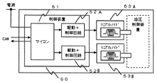
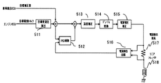
- FIG. 5 is a diagram illustrating an example of an internal configuration of the ATCU 5
- FIG. 6 is a diagram illustrating an example of a control flow of actuator control in the ATCU 5.
- the microcomputer 51 in the ATCU 5 calculates a current command value for the solenoid valve in response to a shift request from CAN (Controller (Area Network).
- CAN Controller (Area Network)
- PID feedback control is performed based on the current deviation between the target current and the monitor current.
- the current temperature of the linear solenoids 53A and 53B is acquired by the temperature sensor mounted on the ATCU 5, the target current is corrected based on this temperature, and the command current is calculated.
- current-duty conversion is performed, an instruction duty is generated, and power supply voltage correction is performed.
- the target speed ratio calculation unit 511 calculates the target speed ratio from the target drive torque supplied from the engine ECU 3 and adds the target speed ratio to the target correction amount supplied from the vehicle integrated ECU 2. .
- the target gear ratio and the target correction amount added to each other are added to the value from the PID control unit 512 and the temperature is corrected by the temperature correction unit 513.
- the duty current converted by the duty converter 514 and corrected by the power supply voltage correction unit 515 is supplied to the linear solenoid 518 via the current detection resistor 517.
- the current flowing through the current detection resistor 517 is detected by the current detection circuit unit 516 and fed back to the PID control unit 512.
- the PID control unit 512 is also supplied with the target gear ratio and the target correction amount added together.
- the actuator control described above is a known actuator control, but in the present invention, the target correction ratio calculated from the target drive torque from the engine ECU 3 is added to the target speed change ratio from the vehicle integrated ECU 2 so that the vehicle It is possible to issue an actuator command that takes into account the performance of
- the deterioration of the vehicle component parts is detected and the drive instruction to the transmission 16 side is corrected, so that the driving force source and the power characteristics of the transmission 16 are caused by factors such as aging deterioration during automatic driving. Even if the vehicle changes, the vehicle behavior (performance) can be stabilized for a long period of time. It has the effect of reducing pleasure.
- the transmission 16 is a torque amplifier
- the fluctuation in the rotational speed is small compared to the case where correction is made with a driving force source, leading to improvement in drivability.
- the present invention can also be applied to a vehicle that does not have an automatic driving function.
- the vehicle behavior is detected based on an existing G sensor (acceleration sensor), and performance change information is acquired according to the present invention.
- the target correction amount calculation unit are mounted in the engine ECU 3, and the function of the present invention can be implemented by transmitting the target correction amount to the ATCU 5 during vehicle control.
- the deterioration of the vehicle component performance is determined from the fluctuation of the acceleration and the driving force in the transition region, and the transmission 16 is corrected for driving. Applicable to change. That is, even if the vehicle parts are not deteriorated, the operation performance may change within the normal range depending on the driving operation continuation time from the start of the vehicle. Even in such a case, the relationship between the ion or water temperature and the performance of the vehicle component is obtained in advance by a sensor such as an ion sensor or a water temperature sensor, and the transmission 16 is driven based on the detected ion or water temperature. Correction can be performed. In such a configuration, it is not necessary to perform the vehicle component deterioration determination timing under a certain ambient environment, and drive correction can be performed at a desired timing.
- the vehicle attitude control ECU 7 which is a performance change information acquisition unit determines whether there is a certain performance change in the information regarding the performance change of the vehicle component since it has been acquired, and determines that there is a certain performance change.
- the vehicle component in which the time change in performance occurs is identified and notified to the driver, and the vehicle component information in which the time change in performance occurs is stored in the nonvolatile memory as vehicle component abnormality information. It can be configured to be memorized.
- the vehicle behavior sensor (acceleration sensor) is caused by running the vehicle again based on the control content (automatic driving control or the like) generated in advance. If the vehicle attitude control ECU 7 determines that the vehicle behavior information (acceleration, pitch, etc.) output from the vehicle attitude control ECU 7 is normal, the abnormality stored in the nonvolatile memory is acquired. It can also be configured to erase information.
- the performance change information acquisition unit vehicle attitude control ECU 7 drives the vehicle based on the control content generated in advance, and is output from the vehicle behavior sensor 4 in addition to the road surface condition, vehicle speed, throttle opening, or target drive torque information.
- the vehicle behavior information is acquired, and the performance information is sequentially stored in the nonvolatile memory 56.
- correction amount can be stored in the nonvolatile memory 56 when the ignition switch of the vehicle is turned off (at the end of the driving cycle).
- the correction amount stored in the non-volatile memory 56 is read when the ignition switch is turned on next time, and the control content (automatic operation) generated in advance during the first run after the ignition switch is turned on.
- the target gear ratio determined by the target drive torque determined based on the control or the like can be corrected.
- SYMBOLS 1 ... Gateway ECU, 2 ... Vehicle integrated ECU, 3 ... Engine ECU, 4 ... Vehicle behavior sensor, 5 ... AT ECU, 6 ... Engine, 16 ... Transmission, 7 ... Vehicle attitude control ECU, 8 ... Recognition system sensor, 21 ... Own vehicle position peripheral space recognition unit, 22 ... Target activation calculation unit, 23 ... Target vehicle speed calculation unit, 31 ... Target Acceleration calculation unit, 32 ... target engine torque calculation unit, 33 ... target drive torque calculation unit, 54 ... target gear ratio calculation unit, 55 ... corrected target gear ratio calculation unit, 56 ... Nonvolatile memory, 41 ... acceleration sensor, 42 ... yaw rate sensor, 43 ... vehicle speed sensor, 71 ... vehicle behavior detection unit, 72 ... performance change information acquisition unit, 73 ... target correction Quantity calculation unit, 81... Camera, 82. Over
Landscapes
- Engineering & Computer Science (AREA)
- Mechanical Engineering (AREA)
- Chemical & Material Sciences (AREA)
- Combustion & Propulsion (AREA)
- Transportation (AREA)
- General Engineering & Computer Science (AREA)
- Automation & Control Theory (AREA)
- Human Computer Interaction (AREA)
- Control Of Transmission Device (AREA)
- Control Of Driving Devices And Active Controlling Of Vehicle (AREA)
- Control Of Vehicle Engines Or Engines For Specific Uses (AREA)
Abstract
本発明は、動力発生装置や動力伝達置の動力特性が変化した場合でも、車両構成部品の劣化を検知し、動力伝達装置への駆動指示を補正し、車両挙動を長期的に安定可能な車両制御装置を実現する。本発明は、所定の車両環境状態にて、車両挙動センサ(4)により過渡領域における駆動力及び加速度の変動を測定し、基準変動と比較し、車両構成部品の劣化を検知する。検知した車両構成部品の劣化に応じて変速機(16)側への駆動指示を補正する。これにより、自動運転時において、車両構成部品の経年劣化などの要因により駆動力源や変速機(16)の動力特性が変化した場合でも、車両挙動(性能)を長期的に安定させることができる。
Description
本発明は、車両挙動(性能)を安定させるための車両制御装置に関する。
自動運転システムにおいて、センサ情報や地図情報を用いた空間認識、及び経路を生成する認識系制御、生成された経路から、エンジン、ステアリング、ブレーキといったアクチュエータECUへの指令値を生成する車両系制御といった一連のデータの流れを網羅した制御アーキテクチャが提案されている。
ここで、アクチュエータECUは、車両運動を統括するECU(ここでは、車両統括ECUとする)からの駆動指令に基づきアクチュエータを制御する。パワートレイン領域では、車両統括ECUからエンジン制御ECUへ駆動指令を行うことで、エンジン制御ECUで算出されたトルク情報を基に変速制御ECUは変速制御を実施し、自動運転を実現している。つまり、自動運転システムとなっても、自動制御しているのはエンジン、詳しくはスロットルであり、自動変速機側は自動化されていない自動運転システムが存在する。
ここで、エンジンや自動変速機の経年劣化により動力特性が変化した場合の補正技術として、以下のような公知技術が知られている。
例えば、駆動力源としてのエンジンとモータを持つハイブリッド(HEV)車両において、それぞれの経年変化や機差による出力トルクの実際値と指令値との誤差を補償して、エンジン走行とモータ走行との切替え時の駆動トルク段差を抑制する技術がある。
詳しくは、有段自動変速機の動力伝達を遮断した状態で、エンジンとモータとの間のクラッチを締結し、エンジンをある指令値により駆動することにより、モータ側でトルクモニタを行う。ここで、エンジンとモータとの間のトルク誤差を検出することで、エンジン走行からモータ走行への駆動切替え時のトルク段差を抑制するものである(特許文献1に記載の技術)。
また、例えば、駆動力源から付与される変速機への入力軸トルクにより実行される回転同期制御を伴うコーストダウンシフト時の変速ショックを抑制する技術がある。詳しくは、回転同期制御を実行するときの入力軸トルクの変化率を、コーストダウンシフトに関与する解放側クラッチの差回転速度の領域に応じて、相対的に抑制するものである(特許文献2に記載の技術)。
また、例えば、出力軸回転センサによりエンジンの出力特性を推定することで、動力特性に経時変化が生じた場合でも、スロットルを制御することで変速ショックを低減する技術がある(特許文献3に記載の技術) また、例えば、変速線を燃費効率マップに基づいて作成し、更に、走行中に燃費効率マップを学習し、学習した燃費効率マップに基づき、常に、使用するエンジン回転域が燃費効率の良い領域になるように、変速線を補正することで、経年変化しても、常に良好な燃費効率を維持する技術がある(特許文献4に記載の技術)。
さらに、例えば、有段自動変速機を備えた自動車の制御装置においては、変速ショックを低減するために、出力軸回転数の変化率及び動力特性等の情報からクラッチの切り換わり時期を正確に検出することにより、出力軸トルクの抑制制御を的確なタイミングで実行するものが知られている。
しかしながら、特許文献1に記載された技術は、比較的経年劣化の少ないモータでトルクモニタを行うことで、エンジンの動力特性の変化を把握することにより、エンジン走行からモータ走行に移行する際のトルク段差を抑制しようとするものであり、駆動切替え時には、性能の劣る方に合わせる為、車両としての性能低下に繋がってしまう。
また、特許文献1に記載の技術では、駆動力源の面しか考慮されていない為、駆動力源と変速機側との同期がとれない場合があり、通常の手動運転であれば、運転者が動力特性の劣化を感覚的に検知し、アクセルを踏み増すなど、自動的にフィードバック制御を行うが、自動運転の場合、変速機側の経年劣化により目標変速段(又は目標レシオ)に遷移するタイミングがずれることにより、過渡領域では、エンジンの吹け上がりやストールが発生する課題がある。
特許文献2に記載の技術については、回転同期制御を伴うコーストダウンシフト時の変速ショックを抑制する技術であり、自動運転時の運転シーンが網羅されているとは言い難く、また、作動油(ATF)の経時変化に応じて入力軸トルクの変化率を変更するとされているが、経時変化の定義が、油温しか定義されてなく、経年劣化時の粘性変化は考慮されていない。
特許文献3に記載の技術については、特許文献1に記載の技術と同様に、駆動力源のトルク特性の経時変化を検出しているが、特に有段自動変速機側のクラッチ滑りや作動油の経時変化が考慮されていない為、駆動力源と変速機側との同期がとれない場合があり、通常の手動運転であれば、運転者が動力特性の劣化を感覚的に検知し、アクセルを踏み増すなど、自動的にフィードバック制御を行うが、自動運転の場合、変速機側の経年劣化により目標変速段(又は目標レシオ)に遷移するタイミングがずれることにより、過渡領域では、エンジンの吹け上がりやストールが発生する課題がある。
さらに、特許文献4に記載の技術についても、特許文献1に記載の技術と同様に、駆動力源のトルク特性の経時変化を検出しているが、特に有段自動変速機側のクラッチ滑りや作動油の経時変化が考慮されていない為、駆動力源と変速機側との同期がとれない場合があり、通常の手動運転であれば、運転者が動力特性の劣化を感覚的に検知し、アクセルを踏み増すなど、自動的にフィードバック制御を行うが、自動運転の場合、変速機側の経年劣化により目標変速段(又は目標レシオ)に遷移するタイミングがずれることにより、過渡領域では、エンジンの吹け上がりやストールが発生する課題がある。
本発明は、上記課題に鑑みてなされたものであり、その目的は、自動運転時において経年劣化などの要因により、動力発生装置や動力伝達置の動力特性が変化した場合でも、車両構成部品の劣化を検知し、動力伝達装置への駆動指示を補正し、車両挙動(性能)を長期的に安定可能な車両制御装置を実現することである。
上記目的を達成するため、本発明は以下のように構成される。
車両制御装置において、予め生成された制御内容に基づいて車両を駆動する駆動トルク発生機構の目標駆動トルクを決定し、上記駆動トルク発生機構の動作を制御する目標駆動トルク決定部と、上記目標駆動トルクに基づいて目標変速比を決定する変速機及び上記駆動トルク発生機構の少なくとも一つを含む車両構成部品の性能の変化に関する情報を取得する性能変化情報取得部と、上記目標駆動トルクに基づいて決定された目標変速比を、上記性能の変化に関する情報に応じて補正する目標変速比補正部とを備える。
本発明によれば、自動運転時において経年劣化などの要因により、動力発生装置や動力伝達置の動力特性が変化した場合でも、車両構成部品の劣化を検知し、動力伝達装置への駆動指示を補正し、車両挙動(性能)を長期的に安定可能な車両制御装置を実現することができる。
以下、本発明の実施形態を、図面を用いて説明する。
図1は本発明の一実施例による自動運転におけるパワトレ系を抜粋したシステム構成図であり、図7は本発明とは異なる例であり、自動運転におけるパワトレ系を抜粋したシステム構成の一例を本発明と比較するために示した図である。
本発明の一実施例の説明に先立って、図7に示した比較例について説明する。
図7において、車両統合ECU12は、レーダーやカメラなどから環境情報及び自車周辺地図情報(道路の勾配、道路の曲率半径)を取得し、目標軌道算出を行う。続いて、車両統合ECU12は、目標軌道から目標車速を算出し、ゲートウェイECU11を介してエンジンECU13に情報を送信する。
エンジンECU13は、現在の実車速と目標車速とから目標加速度を算出し、目標加速度に対応した目標エンジントルクを決定する。ここで、エンジンECU13は、目標エンジントルクにすべくエンジン6を制御し、同時に変速機ECU15(ATCU)には、推定エンジントルクと路面に伝えるべき目標駆動トルク情報を送信し、エンジン6と変速機間の同期をとろうとしている。
しかし、この図7に示した構成では、経年劣化に関してエンジン6側しか考慮されていない為、少なからずエンジン6と変速機間の同期がとれない場合があり、通常の手動運転であれば、運転者が動力特性の劣化を感覚的に検知し、アクセルを踏み増すなど、運転者によりフィードバック制御が行われるが、自動運転の場合、変速機1の経年劣化により実変速比が目標変速比まで達しないために、過渡領域では、エンジン6の吹け上がりやストールが発生する可能性がある。
これに対して、図1に示す本発明のシステム構成では、車両統合ECU2の接続先に、ゲートウェイECU1を介してエンジンECU3だけでなく、ATCU5も追加されている。さらには、構成部品の経年劣化による車両挙動を検知するため、車両挙動センサ4からの信号も車両統合ECU2に供給される構成となっている。車両挙動センサ4とは、加速度センサ41、ヨーレートセンサ42、及び車速センサ43である。
図1に示した本発明の一実施例の構成によれば、自動運転による走行時、車両挙動センサ4からの情報を基に、性能変化情報取得ECU(車両姿勢制御部)でパワートレイン系の経年劣化を検知することができる。ここでは、厳密に異常部位の特定をする必要は無く、パワートレイン系の劣化というレベルの検知で良い。その理由としては、本発明は、パワートレイン系の最終段である変速機16側でアクチュエータ指令値を補正するためであり、応答性の速い変速機16で経年劣化分を補正することにより、車両挙動を安定化させる効果がある。
ここで、車両の駆動トルク発生機構であるエンジン6は、決定された目標駆動トルクに基づいて、目標駆動トルク決定部であるエンジンECU3によりフィードバック制御され、後述するように、変速機16は、目標駆動トルクに基づいて目標変速比補正部であるATCU5によりフィードフォワード制御される。
図2は、車両挙動センサから、自動変速機16から出力される駆動トルクまでの制御フローを示す図である。
図2において、まず、初めに車両統合ECU2は、MPU9からの地図情報と、カメラ81及びレーダー82を有する認識系のセンサ8からの情報とにより、自車位置周辺空間認識部21が空間認識を行い、目標軌道算出部22が目標軌道の算出を行う。
次に、目標車速算出部23が目標軌道を走行可能な目標車速を算出し、エンジンECU3の目標加速度算出部31に情報を送信する。目標加速度算出部31には、実車速情報も供給されており、目標加速度算出部31は、現在の実車速と目標車速から目標加速度を算出する。そして、算出された目標加速度が目標エンジントルク算出部32に供給され、目標加速度に対応した目標エンジントルクが決定される。そして、目標駆動トルク算出部33は、目標エンジントルクにすべくエンジンへの供給燃料、点火時期及びスロットル制御を行い、同時にATCU5の目標変速比算出部54には、推定エンジントルクと路面に伝えるべき目標駆動トルク情報を送信する。
上記処理と並行して、車両姿勢制御ECU7の車両挙動検出部71は、車両挙動センサ4からの情報(加速度、ヨーレート、車速)を検出し、検出した車両挙動情報を基に、性能変化情報取得部72でパワートレイン系の経年劣化を検知する。パワートレイン系の経年劣化を検知については後述する。目標補正量算出部73では、車両挙動の変化率より、変速機16に対する目標補正量を算出し、ATCU5の補正後目標変速比算出部55に情報を送信する。
ATCU5の補正後目標変速比算出部55では、エンジンECU3からの目標駆動トルク情報と、車両姿勢制御ECU7からの目標補正量とから、補正後目標変速比を算出し、変速機16内のアクチュエータを制御する(ソレノイド駆動制御)ことで、駆動トルクを出力する。上述した、性能変化情報取得部72によるパワートレイン系の経年劣化検知は、特定の条件で実施され、補正後目標変速比へフィードバックされる。なお、目標補正量算出部73で算出された目標補正量は、不揮発性メモリ56に記憶される。
なお、図2では、車両姿勢制御ECU7は、車両統合ECU2と別箇のECUとしたが、車両姿勢制御ECU7は車両統合ECU2に含むことが可能である。
図3は、本発明の一実施例における自動運転経年劣化補正制御の制御フローである。
図3のステップS401は、自動運転で車両走行中、地図情報を基に現在の走行環境が、経年劣化補正制御の実施条件か否かを車両統合ECU2が判定するステップである。
これは、後述する経年劣化判定において、現在の車両環境と車両情報データベース(以下、車両情報DB)を比較し劣化判定を行うが、両者の比較は、車両環境を合わせる必要があり、即ち車両情報DBには、車速、スロットル開度、変速比、路面勾配、車両挙動等の大量のデータが必要となる。そのため、経年劣化補正制御を常時実施すると、CPUに対する処理負荷、及びメモリ消費量が高くなってしまい、本来行うべき変速制御に遅延が発生する懸念がある。即ち、CPUに対する処理負荷、及びメモリ消費量を小さくするため、予め経年劣化補正制御を実施するタイミングを決めておく必要がある。このため、地図情報から道路の勾配、道路の曲率半径を取得し、取得した道路の勾配、道路の曲率半径が所定の条件を満たすときのみ経年劣化補正制御を実施する。
しかし、本発明に適用されるシステムのCPUの処理負荷、及びメモリ消費量が、本来行うべき変速制御に影響を与えない場合には、経年劣化補正制御を常時実施することも可能である。
ステップS401において、経年劣化補正制御の実施が可能と判定された場合は、ステップS402に進む。
ステップS402は、経年劣化補正制御が実施可能と判断された際の車両環境情報を取得するステップである。詳しくは、車速、スロットル開度、変速比、路面勾配、曲率半径(アール)等を取得するものであり、その目的としては、車両情報DBと比較する際、取得あるいは経年劣化判定のタイミングの問題で、いずれかの情報に差異があった場合には、経年劣化判定の中止、又は、差異情報に基づいた目標補正量の算出を行うためである。
次に、ステップS403に進む。ステップS403は、経年劣化補正制御が実施可能と判断された際の車両挙動情報を取得するステップである。その目的としては、ステップS402と同様、車両情報DBと比較する際、取得、あるいは経年劣化判定のタイミングの問題で、いずれかの情報に差異があった場合には、経年劣化判定の中止、又は、差異情報に基づいた目標補正量の算出を行うためである。
次にステップS404に進み、経年劣化補正制御の実施条件が成立している場合の、車速、スロットル開度、変速比、路面勾配、車両挙動等のデータをデータベース化する。車両情報DBは、任意で取得したタイミングの車両情報の他、情報取得タイミングに至るまでのアクチュエータ操作量に対する車両挙動をデータベース化し、構成機関の動力特性の経時変化を確認できるように構成することで、構成機関の動力特性の変化が、経時劣化であるか、故障によるものであるかを判定できることを目的としている。
次に、ステップS405に進む。ステップS405は、経年劣化補正制御の実施条件が成立している場合における、経年劣化判定を行うステップである。現在の車両挙動と車両情報DBとを比較し劣化判定を行うが、このステップで経年劣化なしと判断された場合には、部品交換や、消耗品の交換によって動力特性が改善されたと判断できるため、ステップS406で運転者への劣化状況の報知を解除する。
ここで、経年劣化判定について、図4を参照して説明する。図4は動力性能の劣化を検知する原理の説明図である。図4において、目標駆動力を立ち上げると、過渡領域を経過した後に、定常領域となり、実駆動力及び加速度が安定する。動力性能が劣化すると、過渡領域における変動が、劣化していない場合(細い実線)の基準変動と劣化している場合(太い実線)の変動とは異なるものとなる。このため、動力性能が劣化していない場合の、実駆動力及び加速度の過渡領域における基準変動を車両情報DBに記憶しておき、検出した実駆動力及び加速度の過渡期における変動と比較することにより、劣化判定を行うことができる。
加速度は次式(1)により算出し、駆動力は、次式(2)により算出することができる。
加速度(km/h2)=駆動力(N)/車重(kg) ・・・(1)
駆動力(N)=エンジントルク(Nm)×変速比/タイヤ半径(m)・・・(2)
ステップS406で運転者への劣化状況の報知を解除した後、処理はステップS407に進み、ATCU5内の不揮発性メモリ56に記憶された目標補正量を初期化(詳しくは補正量をゼロとする)し、処理は終了する。
駆動力(N)=エンジントルク(Nm)×変速比/タイヤ半径(m)・・・(2)
ステップS406で運転者への劣化状況の報知を解除した後、処理はステップS407に進み、ATCU5内の不揮発性メモリ56に記憶された目標補正量を初期化(詳しくは補正量をゼロとする)し、処理は終了する。
このように、自動的に目標補正量を初期化する仕組みとすることで、ディーラー等では標準的に所有している診断ツールを持たずとも、異常情報のクリア処理が行えることになり、サービス性の向上を図ることができる。
ステップS405において、経年劣化補正制御の実施条件が成立している場合であって、経年劣化ありと判断された場合はステップS408に進み、運転者への劣化状況の報知を行う。その後、ステップS409にて、変速機制御に対する目標補正量の算出を行うが、本処理はアクチュエータECU側、即ちATCU5側に実装しても問題は無い。
ATCU5では、エンジンECU3から受信した推定エンジントルク情報、目標変速比情報を基に、アクチュエータへの駆動指令値を算出し、アクチュエータを駆動制御(ソレノイド駆動制御)するが、アクチュエータ駆動指令算出フローに、車両統合ECU2から受信した目標補正量を加算することで、経年劣化などの要因により駆動力源や変速機16の動力特性が変化した場合でも、車両性能を長期的に安定させることができる(ステップS410)。
その後、ステップS411で、ATCU5内の不揮発性メモリ56にステップS409で算出した目標補正量を記憶し、処理は終了する。ステップS411で、不揮発性メモリ56に目標補正量を記憶させることにより、次周期の制御より本目標補正量がデフォルトで適用される。
一方、ステップS401で、自動運転で車両走行中、地図情報を基に現在の走行環境が、経年劣化補正制御の実施条件ではないと判断された場合、ステップS412に進み、車両統合ECU3は、不揮発性メモリ56に記憶されている目標補正量を読み出す指令をATCU5へ送信する。この目標補正量は、ステップS409で算出されたものであり、これは即ち、現在最新の動力特性の経時変化に対応した補正量となる。
続いて、ステップS413でATCU5は、ステップS410と同様に、エンジンECU3から受信した推定エンジントルク情報、目標変速比情報を基に、アクチュエータへの駆動指令値を算出し、駆動制御するが、アクチュエータ駆動指令算出フローに、車両統合ECU2より受信した目標補正量を加算することで、経年劣化などの要因により駆動力源や変速機16の動力特性が変化した場合でも、車両性能を長期的に安定させることができる。
ここで、変速比及び目標補正量の算出について説明する。過渡領域における加速度偏差(実加速度と記憶された加速度との偏差)から、上記式(1)を用いて、上乗せする補正駆動力を算出する(車重は固定値(既知の値))。そして、上記式(2)により、補正駆動力を実現する変速比を算出する(タイヤ半径は固定値(既知の値)、エンジントルクは目標エンジントルクと仮定)。
目標補正量は、次式(3)により算出される。
目標補正量=補正駆動力(N)×タイヤ半径(m)/目標エンジントルク(Nm)・・・(3)
図5は、ATCU5の内部構成の一例を示す図であり、図6は、ATCU5におけるアクチュエータ制御の制御フローの一例を示す図である。
図5は、ATCU5の内部構成の一例を示す図であり、図6は、ATCU5におけるアクチュエータ制御の制御フローの一例を示す図である。
図5及び図6において、ATCU5内のマイコン51は、CAN(Controller Area Network)からの変速要求によりソレノイドバルブに対する電流指令値を算出する。リニアソレノイド駆動制御部52A、52B内では、まず、目標電流とモニタ電流との電流偏差に基づいてPIDフィードバック制御を行う。ATCU5に実装されている温度センサにより、現在のリニアソレノイド53A、53Bの温度を取得し、この温度を基に目標電流を補正し、指示電流を算出する。次に、ソレノイド53A、53Bを駆動可能な信号に変換する為に、電流-Duty変換を行い、指示デューティを生成し、電源電圧補正を行う。
さらに、詳細には、図6に示すように、エンジンECU3から供給された目標駆動トルクから目標変速比算出部511が目標変速比を算出し、車両統合ECU2から供給された目標補正量と加算する。そして、互いに加算された目標変速比と目標補正量とは、PID制御部512からの値と加算され、温度補正部513により温度補正される。そして、デューティ変換部514によりデューティ変換され、電源電圧補正部515により補正された指示電流が電流検出抵抗517を介してリニアソレノイド518に供給される。
電流検出抵抗517に流れる電流は、電流検出回路部516により検出され、PID制御部512にフィードバックされる。PID制御部512には、上述した互いに加算された目標変速比と目標補正量も供給される。
上述したアクチュエータ制御は、公知のアクチュエータ制御であるが、本発明では、エンジンECU3からの目標駆動トルクに基づき算出した目標変速比に対し、車両統合ECU2からの目標補正量を加えることで、車両としての性能を加味したアクチュエータ指令を行うことが可能となる。
本発明によれば、車両構成部品の劣化を検知し、変速機16側への駆動指示を補正することで、自動運転時において、経年劣化などの要因により駆動力源や変速機16の動力特性が変化した場合でも、車両挙動(性能)を長期的に安定させることができるため、運転者が部品交換をするまでの間、異常を報知すると同時に、性能変化を感じることなく運転できるため、不快感を低減する効果がある。
また、動力特性の変化が駆動力源、変速機16のどちらに発生したとしても、変速機16側の駆動指示値を補正することで、駆動力源と比較し応答性が早い、且つ、変速比を変化させることで、路面への伝達トルクを要求通りに発生することができ、車両挙動を安定的に保つことができる。
また、変速機16がトルク増幅機である特徴を生かし、駆動力源で補正した場合に比べ、回転数変動が小さい為、ドライバビリティ向上にも繋がる。
なお、本発明は、自動運転機能を実装していない車両にも適用可能であり、既存に実装されているGセンサ(加速度センサ)を基に車両挙動を検知し、本発明による性能変化情報取得部、及び目標補正量算出部をエンジンECU3に実装し、車両制御時、ATCU5へ目標補正量を送信することにより、本発明の機能を実施可能である。
また、上述した例は、過渡領域における加速度、駆動力の変動から、車両部品性能の劣化を判断し、変速機16に駆動補正するように構成したが、車両部品性能の時間的経過による性能の変化に対しても適用可能である。つまり、車両部品が劣化していない状態であっても車両の始動時からの運転動作継続時間により動作性能が正常範囲内において変化する場合がある。このような場合であっても、イオンセンサや水温センサ等によるセンサでイオンや水温と、車両部品の性能との関係を予め求めておき、検出したイオンや水温に基づいて、変速機16の駆動補正を行うことが可能である。このように構成した場合は、車両部品の劣化判定タイミングを一定の周囲環境下で行う必要はなく、所望のタイミングで、駆動補正を行うことができる。
また、性能変化情報取得部である車両姿勢制御ECU7は、取得したから車両構成部品の性能の変化に関する情報に一定の性能変化があるか否かを判断し、一定の性能変化があると判定した場合は、性能の時間変化が発生している車両構成部品を特定し、運転者に報知するとともに、性能の時間変化が発生している車両構成部品情報を車両構成部品異常情報として不揮発性メモリに記憶させるように構成することができる。
また、上記性能の時間変化している部位が修理、交換した場合には、再び、予め生成された制御内容(自動運転制御等)に基づいて車両を走行させることで、車両挙動センサ(加速度センサ、ヨーレートセンサ、勾配、車速等)から出力される車両挙動情報(加速度、ピッチ等)を取得することで、車両姿勢制御ECU7で正常と判断した場合には、上記不揮発性メモリに記憶された異常情報を消去するように構成することも可能である。
また、性能変化情報取得部車両姿勢制御ECU7は、予め生成された制御内容に基づいて車両を走行させ、路面状況、車速、スロットル開度または目標駆動トルク情報に加え、車両挙動センサ4から出力される車両挙動情報を取得し、これらの性能情報を不揮発性メモリ56に逐次記憶するように構成することができる。
また、不揮発性メモリ56への補正量の記憶は、車両のイグニッションスイッチがオフ操作された際(ドライビングサイクルの最後)に行うように構成することができる。
また、不揮発性メモリ56に記憶された上記補正量は、次回イグニッションスイッチがオン操作された際に読み出され、イグニッションスイッチオン後、初回の走行時においても、予め生成された制御内容(自動運転制御等)に基づいて決定された目標駆動トルクにより決定された目標変速比に対し補正を行うように構成することができる。
1・・・ゲートウェイECU、2・・・車両統合ECU、3・・・エンジンECU、4・・・車両挙動センサ、5・・・ATECU、6・・・エンジン、16・・・変速機、7・・・車両姿勢制御ECU、8・・・認識系センサ、21・・・自車位置周辺空間認識部、22・・目標起動算出部、23・・・目標車速算出部、31・・・目標加速度算出部、32・・・目標エンジントルク算出部、33・・・目標駆動トルク算出部、54・・・目標変速比算出部、55・・・補正後目標変速比算出部、56・・・不揮発性メモリ、41・・・加速度センサ、42・・・ヨーレートセンサ、43・・・車速センサ、71・・・車両挙動検出部、72・・・性能変化情報取得部、73・・・目標補正量算出部、81・・・カメラ、82・・・レーダー
Claims (11)
- 予め生成された制御内容に基づいて車両を駆動する駆動トルク発生機構の目標駆動トルクを決定し、上記駆動トルク発生機構の動作を制御する目標駆動トルク決定部と、
上記目標駆動トルクに基づいて目標変速比を決定する変速機及び上記駆動トルク発生機構の少なくとも一つを含む車両構成部品の性能の変化に関する情報を取得する性能変化情報取得部と、
上記目標駆動トルクに基づいて決定された目標変速比を、上記性能の変化に関する情報に応じて補正する目標変速比補正部と、
を備えることを特徴とする車両制御装置。 - 請求項1に記載の車両制御装置において、
上記駆動トルク発生機構は、決定された上記目標駆動トルクに基づいて上記目標駆動トルク決定部によりフィードバック制御され、上記変速機は、上記目標駆動トルクに基づいて上記目標変速比補正部によりフィードフォワード制御されることを特徴とする車両制御装置。 - 請求項1に記載の車両制御装置において、
車両の挙動を検知する車両挙動センサを備え、上記性能変化情報取得部は、上記車両挙動センサが検知した車両挙動情報を取得し、取得した上記車両挙動情報から上記車両構成部品の性能の変化に関する情報を取得することを特徴とする車両制御装置。 - 請求項1に記載の車両制御装置において、
前記目標駆動トルク決定部は、予め生成された目標経路に基づいて決定された目標車速、現在車速、路面勾配、周囲環境から目標駆動トルクを決定することを特徴とする車両制御装置。 - 請求項1に記載の車両制御装置において、
上記目標変速比補正部は、上記性能変化情報取得部から性能の時間的変化を取得し、上記目標変速比に対する補正量を決定して、目標変速比を補正することを特徴とする車両制御装置。 - 請求項3に記載の車両制御装置において、
上記性能変化情報取得部は、取得したから上記車両構成部品の性能の変化に関する情報に一定の性能変化があるか否かを判断し、一定の性能変化があると判定した場合は、性能の時間変化が発生している車両構成部品を特定し、運転者に報知するとともに、上記性能の時間変化が発生している車両構成部品情報を車両構成部品異常情報として不揮発性メモリに記憶させることを特徴とする車両制御装置。 - 請求項6に記載の車両制御装置において、
上記性能の時間変化している部品を修理、交換した場合に、再び、予め生成された制御内容に基づいて車両を走行させ、上記車両挙動センサから出力される車両挙動情報を取得し、上記性能変化情報取得部が正常と判断した場合には、上記不揮発性メモリに記憶された上記車両構成部品異常情報は消去されることを特徴とする車両制御装置。 - 請求項1に記載の車両制御装置において、
上記性能変化情報取得部は、地図情報から道路の勾配、道路の曲率半径を取得し、取得した道路の勾配、道路の曲率半径が所定の条件を満たすときのみ上記車両構成部品の性能の変化に関する情報を取得することを特徴とする車両制御装置。 - 請求項1に記載の車両制御装置において、
車両の挙動を検知する車両挙動センサを備え、上記性能変化情報取得部は、予め生成された制御内容に基づいて車両を走行させ、路面状況、車速、スロットル開度または目標駆動トルク情報に加え、上記車両挙動センサから出力される車両挙動情報を取得し、これらの性能情報を不揮発性メモリに逐次記憶することを特徴とする車両制御装置。 - 請求項5に記載の車両制御装置において、
上記目標変速比補正部は、車両のイグニッションスイッチがオフ操作されたときに、上記目標変速比に対する補正量を不揮発性メモリに記憶することを特徴とする車両制御装置。 - 請求項10に記載の車両制御装置において、
上記不揮発性メモリに記憶された上記補正量は、車両のイグニッションスイッチがオン操作された際に読み出され、上記イグニッションスイッチオン操作後、初回の走行時においても、予め生成された制御内容に基づいて決定された上記目標駆動トルクにより決定された上記目標変速比に対し補正が行われることを特徴とする車両制御装置。
Priority Applications (4)
| Application Number | Priority Date | Filing Date | Title |
|---|---|---|---|
| DE112017003361.6T DE112017003361T5 (de) | 2016-08-24 | 2017-07-26 | Fahrzeugsteuervorrichtung |
| CN201780037006.8A CN109661339B (zh) | 2016-08-24 | 2017-07-26 | 车辆控制装置 |
| JP2018535546A JP6695429B2 (ja) | 2016-08-24 | 2017-07-26 | 車両制御装置 |
| US16/326,080 US11505174B2 (en) | 2016-08-24 | 2017-07-26 | Vehicle control device |
Applications Claiming Priority (2)
| Application Number | Priority Date | Filing Date | Title |
|---|---|---|---|
| JP2016163829 | 2016-08-24 | ||
| JP2016-163829 | 2016-08-24 |
Publications (1)
| Publication Number | Publication Date |
|---|---|
| WO2018037815A1 true WO2018037815A1 (ja) | 2018-03-01 |
Family
ID=61246616
Family Applications (1)
| Application Number | Title | Priority Date | Filing Date |
|---|---|---|---|
| PCT/JP2017/026978 Ceased WO2018037815A1 (ja) | 2016-08-24 | 2017-07-26 | 車両制御装置 |
Country Status (5)
| Country | Link |
|---|---|
| US (1) | US11505174B2 (ja) |
| JP (1) | JP6695429B2 (ja) |
| CN (1) | CN109661339B (ja) |
| DE (1) | DE112017003361T5 (ja) |
| WO (1) | WO2018037815A1 (ja) |
Cited By (5)
| Publication number | Priority date | Publication date | Assignee | Title |
|---|---|---|---|---|
| JP2020068512A (ja) * | 2018-10-26 | 2020-04-30 | アイシン精機株式会社 | エレクトロニックコントロールユニット |
| WO2022030206A1 (ja) * | 2020-08-06 | 2022-02-10 | 株式会社デンソー | 車両管理装置、車両管理方法、車両管理プログラム |
| JP2022031125A (ja) * | 2020-08-06 | 2022-02-18 | 株式会社デンソー | 車両管理装置、車両管理方法、車両管理プログラム |
| JP2023091460A (ja) * | 2021-12-20 | 2023-06-30 | トヨタ自動車株式会社 | 車両制御装置、車両制御方法およびプログラム |
| US12559135B2 (en) | 2023-06-07 | 2026-02-24 | Toyota Jidosha Kabushiki Kaisha | Autonomous driving system |
Families Citing this family (4)
| Publication number | Priority date | Publication date | Assignee | Title |
|---|---|---|---|---|
| JP7371561B2 (ja) * | 2020-04-08 | 2023-10-31 | トヨタ自動車株式会社 | 車両管理システム及び情報処理装置 |
| JP7338571B2 (ja) * | 2020-07-02 | 2023-09-05 | トヨタ自動車株式会社 | 劣化推定装置、劣化推定方法、劣化推定プログラム |
| JP7545323B2 (ja) * | 2020-12-28 | 2024-09-04 | カワサキモータース株式会社 | 乗物制御プログラム及び乗物制御装置 |
| KR20230013208A (ko) * | 2021-07-16 | 2023-01-26 | 현대자동차주식회사 | 차량의 통합 제어 시스템 |
Citations (7)
| Publication number | Priority date | Publication date | Assignee | Title |
|---|---|---|---|---|
| JPH0587220A (ja) * | 1991-09-27 | 1993-04-06 | Honda Motor Co Ltd | 自動変速機の制御装置 |
| JP2000045811A (ja) * | 1998-08-03 | 2000-02-15 | Nissan Motor Co Ltd | 車両用駆動力制御装置 |
| JP2003329126A (ja) * | 2002-03-05 | 2003-11-19 | Toyota Motor Corp | 無段変速機の制御装置 |
| JP2005337053A (ja) * | 2004-05-25 | 2005-12-08 | Nissan Motor Co Ltd | 車両用駆動トルク制御装置 |
| JP2006090536A (ja) * | 2004-09-27 | 2006-04-06 | Toyota Central Res & Dev Lab Inc | ベルト式無段変速機の制御装置 |
| JP2009097542A (ja) * | 2007-10-12 | 2009-05-07 | Toyota Motor Corp | 車両用自動変速機の適合支援制御装置 |
| JP2016078704A (ja) * | 2014-10-17 | 2016-05-16 | 日産自動車株式会社 | ハイブリッド車両の制御装置 |
Family Cites Families (25)
| Publication number | Priority date | Publication date | Assignee | Title |
|---|---|---|---|---|
| JP2848101B2 (ja) * | 1991-04-19 | 1999-01-20 | 三菱自動車工業株式会社 | 内燃機関と連続可変変速機との制御装置 |
| JPH09287656A (ja) | 1996-04-22 | 1997-11-04 | Aisin Aw Co Ltd | 自動変速機の制御装置 |
| JP3780117B2 (ja) | 1999-04-28 | 2006-05-31 | 株式会社日立製作所 | 自動車の制御装置 |
| US7023150B2 (en) * | 2000-07-11 | 2006-04-04 | Aisin Aw Co., Ltd. | Drive device |
| JP4931364B2 (ja) * | 2005-04-06 | 2012-05-16 | 本田技研工業株式会社 | 車両用無段変速機の制御装置 |
| JP2006298317A (ja) * | 2005-04-25 | 2006-11-02 | Toyota Motor Corp | 駆動力制御装置 |
| EP1878950A4 (en) * | 2005-04-27 | 2011-06-01 | Tcm Corp | CLUTCH CONTROL DEVICE AND CLUTCH CONTROL METHOD |
| WO2006137591A1 (ja) * | 2005-06-22 | 2006-12-28 | Toyota Jidosha Kabushiki Kaisha | 車両用駆動装置の制御装置 |
| JP2009107436A (ja) * | 2007-10-29 | 2009-05-21 | Toyota Motor Corp | 動力伝達制御装置 |
| JP2010095197A (ja) * | 2008-10-17 | 2010-04-30 | Toyota Motor Corp | 車両用動力伝達装置の制御装置 |
| JP5157942B2 (ja) * | 2009-02-02 | 2013-03-06 | 日産自動車株式会社 | 車両用自動変速機の変速制御装置 |
| JP2010260373A (ja) * | 2009-04-30 | 2010-11-18 | Aisin Ai Co Ltd | 車両の動力伝達制御装置 |
| WO2011074037A1 (ja) * | 2009-12-17 | 2011-06-23 | トヨタ自動車株式会社 | 車両の制御装置 |
| DE102010002764A1 (de) * | 2010-03-11 | 2011-09-15 | Zf Friedrichshafen Ag | Verfahren zur Steuerung einer Getriebebremse |
| JP2012046003A (ja) | 2010-08-25 | 2012-03-08 | Toyota Motor Corp | 車両用動力伝達装置の制御装置 |
| JP5693151B2 (ja) * | 2010-11-01 | 2015-04-01 | ジヤトコ株式会社 | 車両の制御装置 |
| JP2012179955A (ja) | 2011-02-28 | 2012-09-20 | Toyota Motor Corp | ハイブリッド車両の制御装置 |
| JP5658204B2 (ja) * | 2012-07-17 | 2015-01-21 | 本田技研工業株式会社 | 車載内燃機関の制御装置 |
| US9493165B2 (en) * | 2012-12-10 | 2016-11-15 | Nissan Motor Co., Ltd. | Drive force control device and drive force control method for vehicle |
| JP5997362B2 (ja) * | 2013-03-12 | 2016-09-28 | ヤマハ発動機株式会社 | 車両の制御装置及び自動二輪車 |
| JP2015051742A (ja) * | 2013-09-09 | 2015-03-19 | トヨタ自動車株式会社 | 車両の駆動力制御装置 |
| JP6196857B2 (ja) * | 2013-09-13 | 2017-09-13 | ジヤトコ株式会社 | 車両の制御装置 |
| JP5993357B2 (ja) * | 2013-09-13 | 2016-09-14 | ジヤトコ株式会社 | 車両の制御装置 |
| JP5926299B2 (ja) * | 2014-01-23 | 2016-05-25 | 富士重工業株式会社 | 無段変速機の異常検知装置、及び、無段変速機の異常検知方法 |
| JP6252511B2 (ja) * | 2015-02-17 | 2017-12-27 | トヨタ自動車株式会社 | 車両の制御装置 |
-
2017
- 2017-07-26 DE DE112017003361.6T patent/DE112017003361T5/de active Pending
- 2017-07-26 JP JP2018535546A patent/JP6695429B2/ja active Active
- 2017-07-26 WO PCT/JP2017/026978 patent/WO2018037815A1/ja not_active Ceased
- 2017-07-26 US US16/326,080 patent/US11505174B2/en active Active
- 2017-07-26 CN CN201780037006.8A patent/CN109661339B/zh active Active
Patent Citations (7)
| Publication number | Priority date | Publication date | Assignee | Title |
|---|---|---|---|---|
| JPH0587220A (ja) * | 1991-09-27 | 1993-04-06 | Honda Motor Co Ltd | 自動変速機の制御装置 |
| JP2000045811A (ja) * | 1998-08-03 | 2000-02-15 | Nissan Motor Co Ltd | 車両用駆動力制御装置 |
| JP2003329126A (ja) * | 2002-03-05 | 2003-11-19 | Toyota Motor Corp | 無段変速機の制御装置 |
| JP2005337053A (ja) * | 2004-05-25 | 2005-12-08 | Nissan Motor Co Ltd | 車両用駆動トルク制御装置 |
| JP2006090536A (ja) * | 2004-09-27 | 2006-04-06 | Toyota Central Res & Dev Lab Inc | ベルト式無段変速機の制御装置 |
| JP2009097542A (ja) * | 2007-10-12 | 2009-05-07 | Toyota Motor Corp | 車両用自動変速機の適合支援制御装置 |
| JP2016078704A (ja) * | 2014-10-17 | 2016-05-16 | 日産自動車株式会社 | ハイブリッド車両の制御装置 |
Cited By (9)
| Publication number | Priority date | Publication date | Assignee | Title |
|---|---|---|---|---|
| JP2020068512A (ja) * | 2018-10-26 | 2020-04-30 | アイシン精機株式会社 | エレクトロニックコントロールユニット |
| JP7110908B2 (ja) | 2018-10-26 | 2022-08-02 | 株式会社アイシン | エレクトロニックコントロールユニット |
| WO2022030206A1 (ja) * | 2020-08-06 | 2022-02-10 | 株式会社デンソー | 車両管理装置、車両管理方法、車両管理プログラム |
| JP2022031125A (ja) * | 2020-08-06 | 2022-02-18 | 株式会社デンソー | 車両管理装置、車両管理方法、車両管理プログラム |
| JP7447869B2 (ja) | 2020-08-06 | 2024-03-12 | 株式会社デンソー | 車両管理装置、車両管理方法、車両管理プログラム |
| JP2023091460A (ja) * | 2021-12-20 | 2023-06-30 | トヨタ自動車株式会社 | 車両制御装置、車両制御方法およびプログラム |
| JP7521518B2 (ja) | 2021-12-20 | 2024-07-24 | トヨタ自動車株式会社 | 車両制御装置、車両制御方法およびプログラム |
| US12258028B2 (en) | 2021-12-20 | 2025-03-25 | Toyota Jidosha Kabushiki Kaisha | Vehicle control apparatus, vehicle control method, and non-transitory storage medium |
| US12559135B2 (en) | 2023-06-07 | 2026-02-24 | Toyota Jidosha Kabushiki Kaisha | Autonomous driving system |
Also Published As
| Publication number | Publication date |
|---|---|
| US20190176797A1 (en) | 2019-06-13 |
| JPWO2018037815A1 (ja) | 2019-04-18 |
| DE112017003361T5 (de) | 2019-03-21 |
| CN109661339B (zh) | 2022-04-05 |
| US11505174B2 (en) | 2022-11-22 |
| JP6695429B2 (ja) | 2020-05-20 |
| CN109661339A (zh) | 2019-04-19 |
Similar Documents
| Publication | Publication Date | Title |
|---|---|---|
| JP6695429B2 (ja) | 車両制御装置 | |
| US9835210B2 (en) | Apparatus and method for learning clutch torque of dual clutch transmission | |
| US9663107B2 (en) | Launch control method for vehicle with dry-type clutch | |
| CN101713440B (zh) | 车辆的离合器控制装置 | |
| US9869354B2 (en) | Clutch control method of hybrid vehicle | |
| US8734292B2 (en) | Ratio shift control system for an automatic transmission | |
| US20170299000A1 (en) | Method for calibrating a clutch control algorithm | |
| US10677298B2 (en) | Method of learning touch point of dual clutch transmission | |
| US8229635B2 (en) | Control device of automatic transmission | |
| US9822831B2 (en) | Method for learning touch point of dual clutch transmission | |
| KR102551679B1 (ko) | 하이브리드 dct 차량의 클러치 제어방법 | |
| CN109854398B (zh) | 用于利用对于滞后时间的补偿来对燃烧马达的转速进行调节的方法 | |
| US8768588B2 (en) | Transmission and method of shift control for transmission | |
| JP4785888B2 (ja) | 変速機の制御システム | |
| US10006508B2 (en) | Method of controlling clutch of vehicle | |
| US20120031201A1 (en) | Method for detecting a developing torque for a hybrid drive | |
| KR100916459B1 (ko) | 하이브리드 차량의 클러치 특성 보정 방법 | |
| KR102461506B1 (ko) | Amt차량의 클러치 제어방법 | |
| JP6020178B2 (ja) | ハイブリッド車のモータ制御装置 | |
| KR101795282B1 (ko) | 차량용 클러치 제어방법 | |
| JP2008240951A (ja) | クラッチ制御装置 | |
| CN109555796B (zh) | 用于控制车辆的离合器的方法 | |
| US12194862B2 (en) | Electrified vehicle and method for manufacturing electrified vehicle | |
| JP2006283815A (ja) | クラッチ制御装置 | |
| JP2008286055A (ja) | アクチュエータの制御装置 |
Legal Events
| Date | Code | Title | Description |
|---|---|---|---|
| 121 | Ep: the epo has been informed by wipo that ep was designated in this application |
Ref document number: 17843301 Country of ref document: EP Kind code of ref document: A1 |
|
| ENP | Entry into the national phase |
Ref document number: 2018535546 Country of ref document: JP Kind code of ref document: A |
|
| 122 | Ep: pct application non-entry in european phase |
Ref document number: 17843301 Country of ref document: EP Kind code of ref document: A1 |