WO2018037689A1 - 画像処理装置及び画像処理方法 - Google Patents
画像処理装置及び画像処理方法 Download PDFInfo
- Publication number
- WO2018037689A1 WO2018037689A1 PCT/JP2017/022742 JP2017022742W WO2018037689A1 WO 2018037689 A1 WO2018037689 A1 WO 2018037689A1 JP 2017022742 W JP2017022742 W JP 2017022742W WO 2018037689 A1 WO2018037689 A1 WO 2018037689A1
- Authority
- WO
- WIPO (PCT)
- Prior art keywords
- image
- enlarged
- unit
- defect
- enlarged image
- Prior art date
- Legal status (The legal status is an assumption and is not a legal conclusion. Google has not performed a legal analysis and makes no representation as to the accuracy of the status listed.)
- Ceased
Links
Images






Classifications
-
- G—PHYSICS
- G01—MEASURING; TESTING
- G01B—MEASURING LENGTH, THICKNESS OR SIMILAR LINEAR DIMENSIONS; MEASURING ANGLES; MEASURING AREAS; MEASURING IRREGULARITIES OF SURFACES OR CONTOURS
- G01B11/00—Measuring arrangements characterised by the use of optical techniques
-
- G—PHYSICS
- G01—MEASURING; TESTING
- G01B—MEASURING LENGTH, THICKNESS OR SIMILAR LINEAR DIMENSIONS; MEASURING ANGLES; MEASURING AREAS; MEASURING IRREGULARITIES OF SURFACES OR CONTOURS
- G01B11/00—Measuring arrangements characterised by the use of optical techniques
- G01B11/30—Measuring arrangements characterised by the use of optical techniques for measuring roughness or irregularity of surfaces
-
- G—PHYSICS
- G01—MEASURING; TESTING
- G01N—INVESTIGATING OR ANALYSING MATERIALS BY DETERMINING THEIR CHEMICAL OR PHYSICAL PROPERTIES
- G01N21/00—Investigating or analysing materials by the use of optical means, i.e. using sub-millimetre waves, infrared, visible or ultraviolet light
- G01N21/84—Systems specially adapted for particular applications
- G01N21/88—Investigating the presence of flaws or contamination
-
- G—PHYSICS
- G06—COMPUTING OR CALCULATING; COUNTING
- G06T—IMAGE DATA PROCESSING OR GENERATION, IN GENERAL
- G06T1/00—General purpose image data processing
Definitions
- the present invention relates to an image processing apparatus and an image processing method, and more particularly to a technique that makes it easy to compare an entire image of a structure such as a bridge and a partially enlarged image of the entire image.
- the crack defect detection method described in Patent Document 1 acquires an entire image obtained by orthographic transformation based on the focal length of the camera and the known dimensions of the structure from the entire image obtained by photographing a predetermined range of the structure as a whole. Then, the camera is rotated with the same position as the shooting position of the whole image as the base point, and the partial image obtained by dividing and enlarging the predetermined range of the structure is acquired, and further crack defects within the shooting range of the partial image are identified. An enlarged image obtained by enlarging the image so as to be possible is acquired.
- the positional relationship between the whole image and the partial image and the orthographically transformed partial image are obtained, and the orthographically transformed partial image and the enlarged image are collated.
- the positional relationship between the partial image and the enlarged image and the enlarged image obtained by orthographic transformation are obtained.
- Patent Document 1 discloses a whole image obtained by orthogonal projection transformation, a partial image obtained by rotating the camera with the same position as the photographing position of the whole image as a base point, and dividing and enlarging a predetermined range of the structure.
- a specific matching method between the whole image and the partial image there is no description regarding a specific matching method between the whole image and the partial image.
- Patent Document 1 has a description for obtaining a mutual positional relationship by collating an orthographic-transformed partial image and an enlarged image, but relates to a specific collation method between the partial image and the enlarged image. There is no description.
- Patent Document 1 does not describe a countermeasure for a case where an error occurs in the collation between the entire image and the partial image or the collation between the partial image and the enlarged image. If an error occurs in the collation between the entire image and the partial image, or the collation between the partial image and the enlarged image, the mutual positional relationship between the images is also incorrect, and as a result, the position where the crack defect is detected (the predetermined range of the structure) There is a problem that the position of the crack defect) is wrong.
- An object of the present invention is to provide an image processing apparatus and an image processing method.
- an image processing apparatus includes a first image acquisition unit that acquires an entire image indicating a predetermined range of a structure, and enlarges a defect in the structure within the predetermined range.
- a second image acquisition unit that acquires a magnified image photographed in this manner, a collation processing unit that collates the entire image and the magnified image, and calculates positional relationship information related to a region of the magnified image in the entire image;
- a display control unit configured to display the enlarged image and a candidate image corresponding to the candidate region of the enlarged image in the entire image specified based on the positional relationship information on the display unit so as to be comparable.
- the entire image and the enlarged image are collated, and positional relationship information related to the area of the enlarged image in the entire image is calculated.
- the display control unit causes the display unit to display the enlarged image and the candidate image corresponding to the candidate area of the enlarged image in the entire image specified based on the positional relationship information.
- the user visually confirms the enlarged image displayed on the display unit so as to be comparable and the candidate image corresponding to the candidate area of the enlarged image in the entire image, thereby confirming whether the comparison result between the entire image and the enlarged image is appropriate. Can be confirmed. Note that, when the entire image and the enlarged image are appropriately checked, the positional relationship information related to the enlarged image region in the entire image can be calculated without error.
- the collation processing unit detects a plurality of corresponding points having the same feature amount from the entire image and the enlarged image, and the enlarged image or the enlarged image based on the detected plurality of corresponding points. It is preferable to calculate conversion parameters for geometrically converting the entire image as positional relationship information.
- the display control unit combines the enlarged image obtained by geometric conversion based on the conversion parameter with the entire image that is combined with the candidate area corresponding to the enlarged image in the entire image. It is preferable to switch and display the previous whole image on the display unit.
- the enlarged image geometrically converted based on the conversion parameter has the same shape and the same size as the image of the candidate area corresponding to the enlarged image in the entire image. Then, the entire image obtained by synthesizing the geometrically transformed enlarged image in the candidate area corresponding to the enlarged image in the entire image and the whole image before synthesis are switched and displayed on the display unit, thereby easily comparing the two images. be able to.
- the display control unit combines the enlarged image obtained by geometric conversion based on the conversion parameter with the entire image that is combined with the candidate area corresponding to the enlarged image in the entire image. It is preferable to display the previous whole image side by side on the display unit. By comparing the entire image obtained by synthesizing the geometrically transformed enlarged image with the candidate area corresponding to the enlarged image in the entire image and the entire image before synthesis on the display unit, both images can be easily compared. .
- the display control unit includes: an enlarged image; and a converted image obtained by geometrically converting a candidate image corresponding to the enlarged image in the entire image based on the conversion parameter. Is preferably displayed on the display unit.
- a converted image obtained by geometrically converting a candidate image corresponding to the enlarged image in the entire image based on the conversion parameter has the same shape and the same size as the enlarged image. Then, the enlarged image and the converted image obtained by geometrically transforming the candidate image corresponding to the enlarged image in the entire image are switched and displayed on the display unit, so that both images can be easily compared.
- the display control unit includes: an enlarged image; and a converted image obtained by geometrically converting a candidate image corresponding to the enlarged image in the entire image based on the conversion parameter.
- a converted image obtained by geometrically converting a candidate image corresponding to the enlarged image in the entire image based on the conversion parameter are preferably displayed side by side on the display unit.
- the image processing apparatus includes a defect information input unit that inputs defect information including the position and shape of the defect of the structure on the enlarged image, and the display control unit is based on the defect information. It is preferable that the defect drawing line obtained by tracing the defect of the structure is superimposed and displayed on the enlarged image and the entire image displayed on the display unit. Thereby, the defect of a structure can be easily visually recognized on an enlarged image and a whole image.
- the image processing apparatus includes a defect identification unit that performs image analysis of the enlarged image and identifies a defect in the structure, and the defect information input unit inputs defect information from the defect identification unit. Is preferred. Thereby, defect information can be input automatically.
- the defect information input unit includes a pointing device that manually indicates the position and shape of the defect of the structure on the enlarged image. Thereby, defect information can be input manually.
- the defect information it is preferable to include a correction unit that manually corrects the defect information displayed in a superimposed manner. Thereby, when there is an error in the defect information input from the defect identification unit, or when there is an error in the instruction of the defect information by the pointing device, the defect information can be corrected.
- a storage unit that stores drawing data of a structure, and a conversion unit that performs geometric conversion that matches a predetermined range of the structure with a corresponding range of the drawing data.
- a conversion unit that geometrically converts only the defect drawing lines superimposed on the entire image and a data output unit that outputs data indicating the defect drawing lines geometrically converted in association with the drawing data are provided.
- drawing data in which a defect drawing line is drawn can be acquired.
- the defect of the structure is a crack
- the defect identifying unit extracts a crack image indicating the crack of the structure from the enlarged image
- the display control unit is cracked. It is preferable to generate a defect drawing line in which an image is emphasized by luminance or color.
- the defect of the structure is a crack
- the display control unit displays a defect drawing line indicating the crack, a crack width, and a crack indicating an interval between adjacent cracks. Information is preferably displayed on the display unit.
- the defect of the structure is a crack
- the display control unit can display the defect drawing line indicating the crack in a classified manner according to the width of the crack.
- the defect drawing lines are displayed by classification according to the width of cracks (by color coding or selecting crack widths to be displayed).
- the defect of the structure is a crack
- a determination unit that determines a progress level of the crack based on crack information indicating a width of the crack and an interval between adjacent cracks.
- the display control unit classifies and displays the defect drawing lines indicating the cracks according to the determined progress level of the cracks.
- the progress level of a structure crack can be determined by the width of the crack and the distance between adjacent cracks, and the discriminator determines the progress level of the crack based on the crack information indicating the width of the crack and the distance between adjacent cracks.
- the display control unit classifies (for example, color-codes) and displays defect drawing lines indicating cracks according to the determined progress level of the cracks.
- the display control unit display a frame indicating a candidate area corresponding to an enlarged image in the entire image on the display unit.
- the enlarged image and the candidate image corresponding to the candidate region of the enlarged image in the entire image can be displayed in a more comparable manner.
- the collation processing unit collates the entire image and the plurality of enlarged images
- a plurality of pieces of positional relationship information related to the candidate areas of the plurality of enlarged images are calculated
- the display control unit corresponds to one enlarged image selected from the plurality of enlarged images and the selected one enlarged image.
- the candidate image corresponding to the candidate region of the selected one enlarged image in the entire image specified based on the positional relationship information is displayed on the display unit so as to be comparable.
- the collation processing unit collates the entire image and the enlarged image, and detects a plurality of candidate areas indicating the enlarged image in the entire image, the plurality of candidate areas are detected.
- Each of the plurality of related positional relationship information is calculated, and the display control unit includes a plurality of candidate images corresponding to a plurality of candidate areas of the enlarged image and the enlarged image in the entire image specified based on the plurality of positional relationship information.
- the display control unit includes a plurality of candidate images corresponding to a plurality of candidate areas of the enlarged image and the enlarged image in the entire image specified based on the plurality of positional relationship information.
- an image selection unit that accepts selection of one candidate image among a plurality of candidate images corresponding to the plurality of candidate regions displayed on the display unit is preferably provided.
- a plurality of candidate images corresponding to a plurality of candidate areas of the enlarged image and the enlarged image in the entire image can be compared. Then, by accepting the selection of one candidate image among the plurality of candidate images by the image selection unit, the user can select an area corresponding to the enlarged image in the entire image.
- the entire image displayed on the display unit In the above, a position information receiving unit that receives position information of an image corresponding to the enlarged image is provided, and the matching processing unit re-executes matching between the entire image and the enlarged image based on the position information received by the position information receiving unit. It is preferable.
- the collation processing unit narrows down the collation range in the entire image and re-collates based on the position information of the image corresponding to the enlarged image received by the position information receiving unit (for example, the clicked position information received on the entire image). be able to.
- the structure is a floor slab of a bridge
- the predetermined range is a space between the floor slabs
- the first image acquisition unit is a photograph taken by an imaging device. It is preferable to acquire a floor slab image including two spaces as a whole image. This is because the inspection of the bridge floor slabs is performed at each interval.
- the first image acquisition unit acquires a plurality of divided images obtained by dividing the space into a plurality of times by the imaging device, and acquires the plurality of divisions acquired. It is preferable to generate a floor slab image by combining images and acquire the generated floor slab image as an entire image. A floor slab image (entire image) including one space needs to be photographed with a resolution that can be collated with at least an enlarged image. In some cases, it is not possible to shoot a floor slab image including a gap. In this case, the space is divided into a plurality of times and photographed to obtain a plurality of divided images. Then, the floor image is generated by synthesizing the acquired plurality of divided images.
- An image processing method includes a first image acquisition step of acquiring an entire image showing a predetermined range of a structure, and an enlarged image obtained by magnifying a defect of the structure within the predetermined range.
- a display control step of causing the display unit to display a candidate image corresponding to the candidate region of the enlarged image in the entire image specified based on the information.
- the entire image showing a predetermined range of a structure such as a bridge is compared with an enlarged image of a part of the entire image, the positional relationship information related to the area of the enlarged image in the entire image is calculated, Since the enlarged image and the candidate image corresponding to the candidate area of the enlarged image in the entire image specified based on the positional relationship information are displayed on the display unit so that the comparison is possible, the user can compare with the display unit.
- the displayed enlarged image and the candidate image corresponding to the candidate area of the enlarged image in the entire image can be visually confirmed, and the suitability of the matching result between the entire image and the enlarged image can be confirmed.
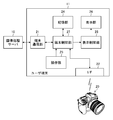
- FIG. 1 is a conceptual diagram of an image processing apparatus according to the present invention.
- the block diagram which shows the function structural example of the user terminal 11 It is a figure which shows an example of the image which image
- the figure which shows the whole image 100 containing one space of a floor slab It is a figure which shows an example of the enlarged image which expanded and image
- Block diagram showing a functional configuration example of the image processing server 10 The figure which shows one Embodiment of the display screen containing the some enlarged image displayed on the display part 26 of the user terminal 11 The figure which shows an example of the display screen of the display part 26 for confirming the correspondence of a whole image and an enlarged image.
- the figure which shows other embodiment of the display screen of the display part 26 for confirming the correspondence of a whole image and an enlarged image It is a figure which shows an example of the display screen of the display part 26 for confirming the correspondence of an entire image and an enlarged image, and is a figure especially when two candidate images corresponding to an enlarged image exist in the entire image.
- FIG. 1 is a conceptual diagram of an image processing apparatus according to the present invention.
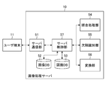
- the image processing apparatus 1 according to the present embodiment includes a user terminal 11 and an image processing server 10 connected to each user terminal 11 via a network 12 such as the Internet.
- the user terminal 11 is a terminal that is operated when the user creates a structure inspection report or the like, and may take the form of a portable terminal such as a personal computer or a tablet device.
- the structure to be inspected in this example is a bridge, and in particular, a case where a floor slab constituting the bridge is to be inspected will be described.
- the bridge is installed in the direction perpendicular to the main girder passed between the abutment and the pier, and the main girder provided in the longitudinal direction of the bridge. It consists of various members including a tilting structure and a horizontal structure that mutually connect the main girders to resist the load, and a floor slab for driving vehicles etc. is placed on the upper part of the main girders etc. Yes.
- the floor slab is generally made of reinforced concrete.
- the floor slab is usually composed of a rectangular space defined by the main girder and cross girder, and damage to the floor slab (cracking, free lime, peeling of concrete, rebar exposure, etc.) When checking, it is done in units of gaps.
- the image processing server 10 generates information necessary for the user to create an inspection report in accordance with an image taken from the inspection target structure (bridge slab) and instructions sent from the user terminal 11. The generated information is returned to the user terminal 11.
- FIG. 2 is a block diagram illustrating a functional configuration example of the user terminal 11.
- the user terminal 11 of this example mainly includes a terminal communication unit 21, an input / output interface 22, an operation unit 23, a storage unit 24, a display control unit 25, a display unit 26, and a terminal control unit 27.
- the terminal communication unit 21 transmits an image of the floor slab taken via the network 12 (see FIG. 1) and an instruction to execute analysis of the image to the image processing server 10, and the image processing server 10 performs image analysis.
- a communication unit that receives an analysis result or the like from the image processing server 10 via the network 12.
- the input / output interface 22 is a part that exchanges information with an external device wirelessly or by wire.
- an image of a floor slab taken by the digital camera (imaging device) 20 is wirelessly transmitted from the digital camera 20. Input by communication.
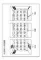
- FIG. 3 is a diagram showing an example of an image obtained by photographing a bridge including a floor slab, and particularly shows a plurality of divided images obtained by dividing one space of the floor slab multiple times.
- a plurality of (three) divided images 100A, 100B, and 100C shown in FIG. 3 are images to be combined by the image processing server 10 into one image as will be described later.
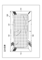
- This single image is an image including one space of the floor slab, and hereinafter, “whole image 100 (FIG. 4) showing a predetermined range of the structure (a range corresponding to one space of the floor slab)”.
- the divided images 100A, 100B, and 100C need to include overlapping regions that overlap between adjacent divided images, and it is preferable that the overlapping regions have about 30% of the total region of each divided image in order to be appropriately combined. .
- the angle of view is determined so as to overlap approximately 30% between adjacent divided images. It is preferable to do.
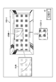
- the entire image 100 includes images 102 and 104 showing a part of the main girder, images 112 and 114 showing a part of the horizontal girder, and a part of the floor slab (the image of the main girder and the horizontal girder).
- 1 image of a single case) (space image) 120 is included.
- the entire image 100 in this example is an image generated by combining three divided images 100A, 100B, and 100C.
- the size of the space is small, and the digital camera 20 can perform one shooting.
- an image (overall image) of a floor slab including one space can be photographed at an appropriate resolution, an image obtained by one photographing may be used.
- the digital camera 20 may be a general-purpose compact digital camera having, for example, about 5000 ⁇ 4000 pixels.
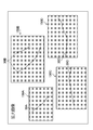
- FIG. 5 is a view showing an example of an enlarged image obtained by enlarging a defect in a predetermined range (space) of the floor slab, and in particular, a plurality of images obtained by enlarging a crack which is one of the defects of the floor slab. The enlarged image is shown.
- FIG. 5 Multiple (four) enlarged images 150A, 150B, 150C, and 150D shown in FIG. 5 are taken at a resolution that can identify cracks (crack width, length, etc.) that are one of the floor plate defects by image analysis. It has been done.
- reference numerals 30 ⁇ / b> A, 30 ⁇ / b> B, 30 ⁇ / b> C, and 30 ⁇ / b> D are crack images showing cracks generated on the floor slab. Note that the crack image 30B shows two cracks, and the crack images 30C and 30D each show a part of one crack.
- the enlarged image it is necessary to determine the resolution of the enlarged image according to the minimum width of the crack that needs to be identified by image analysis. For example, when the crack width of 0.1 mm needs to be identified by image analysis, the enlarged image Needs to be photographed at a resolution higher than a crack width of 0.1 mm.
- the floor slab image (divided image for synthesis shown in FIG. 3, enlarged image shown in FIG. 5) captured by the digital camera 20 is input from the digital camera 20 via the input / output interface 22.
- the data is taken into the user terminal 11 and stored in the storage unit 24.
- the operation unit 23 includes a mouse, a pointing device including the touch panel when the display unit 26 has a touch panel, and a keyboard, and is used to operate a pointer and an icon displayed on the screen of the display unit 26.
- the storage unit 24 stores an image of the floor slab input via the input / output interface 22, and in this example, the user terminal 11 is dedicated for functioning as a part of the image processing apparatus according to the present invention. Software is stored, and further data indicating a defect drawing line to be described later is stored.
- the terminal control unit 27 is a part that executes software stored in the storage unit 24 in response to an input from the operation unit 23 and performs overall control of each unit of the user terminal 11.
- the display control unit 25 controls the entire display screen to be displayed on the display unit 26 based on various data and commands including images input from the terminal control unit 27.
- the display control unit 25 mainly displays an enlarged image obtained by enlarging a defect of the structure (floor slab) and an enlarged image candidate area in the entire image indicating a predetermined range of the structure (a space between floor slabs).
- the corresponding candidate image is displayed on the display unit 26 so as to be comparable (display control step). Details of various display screens displayed on the display unit 26 by the display control unit 25 will be described later.
- Image processing server 10 a functional configuration of the image processing server 10 constituting the image processing apparatus 1 will be described.
- FIG. 6 is a block diagram illustrating a functional configuration example of the image processing server 10.
- the image processing server 10 of this example mainly includes a server communication unit 51, an image DB (DB) 52 that functions as an image storage unit, a drawing DB 53 that stores structure drawing data, a verification processing unit 54, and a defect identification unit. 55, a conversion unit 56, and a server control unit 57.
- DB image DB
- the image DB 52 and the drawing DB 53 are configured to include one or a plurality of hard disk devices.
- the verification processing unit 54, the defect identification unit 55, the conversion unit 56, and the server control unit 57 are stored in one or a plurality of CPUs (Central / Processing / Units), a working memory of the CPU, a hard disk device, and the like, and are expanded on the memory.
- the image processing program is executed, and the CPU executes the image processing program, and functions as each unit.
- the server communication unit 51 receives an image of the floor slab and an instruction to execute analysis of the image from the user terminal 11 via the network 12 (see FIG. 1), an analysis result obtained by image analysis by the image processing server 10, and the like. Is a communication unit that transmits to the user terminal 11 via the network 12.
- the image DB 52 is a storage unit that stores images (divided images, whole images, enlarged images, etc.) received from the user terminal 11 via the server communication unit 51 under the control of the server control unit 57.
- a plurality of divided images (or entire images) and one or a plurality of enlarged images are stored in association with each other in units of spaces.
- the drawing DB 53 is a storage unit that stores drawing data of structures, and stores and manages drawing data (CAD (computer-aided design) drawings) of a plurality of bridges (including floor slabs).
- drawing data CAD (computer-aided design) drawings
- the drawing data saving method is not limited to this.
- FIG. 15 shows an entire image 100 including a space image 120 showing one space, and a floor plan drawing 200 indicated by a dotted line. These whole image 100 and drawing 200 can be displayed on the display unit 26 of the user terminal 11. The floor plan drawing 200 can be displayed on the display unit 26 based on the drawing data stored in the drawing DB 53.
- Mg01 to Mg03 are member numbers of main beams (Mg: Main : girder), and Cr01 to Cr05 are member numbers of horizontal beams (Cr: Cross beam). If the entire floor deck drawing of the bridge cannot be displayed properly on one screen (when the total length of the bridge is long), it is possible to display a partial drawing of the floor slab and scroll the floor plan drawing. It is preferable to do so.
- the user When uploading an image of a floor slab from the user terminal 11 to the image processing server 10, the user transmits information specifying the inspection target bridge (floor slab) to the image processing server 10, and the image processing server 10 Get drawing data.
- the image processing server 10 acquires information specifying the floor slab from the user terminal 11, the image processing server 10 can read the corresponding drawing data from the drawing DB 53 and transmit the read drawing data to the user terminal 11.
- the display control unit 25 of the user terminal 11 displays the floor slab drawing 200 (FIG. 15) on the display unit 26 based on the drawing data acquired from the image processing server 10 and also stores the floor slab stored in the storage unit 24.
- a list of images (a divided image for synthesis, an entire image, and an enlarged image) is displayed.
- the user specifies one space in the floor slab drawing 200, drags and drops a plurality of composite divided images or entire images corresponding to the space, and specifies the space between floor slabs. Are associated with a plurality of divided images or entire images. Similarly, dragging and dropping the enlarged image to the specified space and associating the floor slab space with the enlarged image.
- the storage unit 24 when the image of the floor slab is managed by a folder for each case, a case in which one case in the drawing 200 is specified and a folder corresponding to the case is specified is specified. It is also possible to associate the floor slab space with the image of each space by dragging and dropping. Further, when uploading a plurality of divided images for synthesis to the image processing server 10, it is preferable to specify and upload the positional relationship within the space between the plurality of divided images 100A, 100B, and 100C as shown in FIG. . This is because the image processing server 10 reduces the calculation load of the synthesis process for synthesizing one whole image 100 from the plurality of divided images 100A, 100B, and 100C.
- a plurality of divided images or entire images for composition for each space associated with the space between floor slabs are processed from the terminal communication unit 21 of the user terminal 11 via the network 12 and the server communication unit 51.
- the server communication unit 51, the server control unit 57, and the image DB 52 function as a first image acquisition unit that acquires an entire image (including a plurality of divided images for composition) indicating a floor slab space, This 1st image acquisition part acquires the whole image which shows the space of a floor slab (1st image acquisition process).
- the enlarged image for each space associated with the floor space is acquired from the terminal communication unit 21 of the user terminal 11 to the image processing server 10 via the network 12 and the server communication unit 51, and the server control unit 57.
- the image is stored in the image DB 52 under the control of the above.
- the server communication unit 51, the server control unit 57, and the image DB 52 function as a second image acquisition unit that acquires an enlarged image, and the second image acquisition unit detects defects in the floor slab space.
- An enlarged image obtained by enlarging the image is acquired (second image acquisition step).
- the server control unit 57 functioning as a part of the first image acquisition unit reads a plurality of divided images for synthesis from the image DB 52, combines the plurality of divided images, and stores one of the floor plates. A floor slab image including a gap is generated, and the generated floor slab image is acquired as an entire image.
- the three divided images 100A, 100B, and 100C are images that are obtained by dividing one space of the floor slab into three portions, and the photographing direction and the photographing position by the digital camera 20 are different, respectively. Between adjacent divided images (the divided image 100A and the divided image 100B, and the divided image 100B and the divided image 100C) include overlapping regions that overlap each other.
- the server control unit 57 detects a plurality of corresponding points having the same feature amount (local feature amount) from overlapping regions between adjacent divided images.
- SIFT Scale-invariant feature transform
- SURF Speed-Upped Robust Feature
- AKAZE Accelerated KAZE
- the transformation parameters for projective transformation refer to the eight parameters a, b, s, c, d, t, p, and q in [Formula 1]. Further, (x, y) and (X, Y) indicate coordinate values before and after projective transformation, respectively.
- eight conversion parameters used for projective transformation can be calculated by establishing eight simultaneous equations by substituting the coordinate values of the four corresponding points into the equation [1] and solving the eight simultaneous equations. it can.
- a conversion parameter for projective conversion of the divided image 100B when the divided image 100A is used as a reference is calculated, and divided using a projective conversion formula having the calculated conversion parameter.
- the image 100B is projectively transformed, and the divided image 100A and the divided image 100B obtained by the projective transformation are combined.
- a conversion parameter for projective conversion of the divided image 100C based on the projection-converted divided image 100B is calculated, and the divided image 100C is projectively converted using a projective conversion formula having the calculated conversion parameter.
- the divided image 100B synthesized by projective transformation and the divided image 100C obtained by projective transformation are synthesized.
- FIG. 4 is a diagram showing the entire image 100 generated by combining the three divided images 100A, 100B, and 100C shown in FIG. 3 as described above.
- the entire image 100 is stored in the image DB 52, transmitted to the user terminal 11, and stored in the storage unit 24 of the user terminal 11.
- FIG. 7 is a diagram illustrating an embodiment of a display screen including a plurality of enlarged images displayed on the display unit 26 of the user terminal 11.
- the image processing server 10 When the user requests the image processing server 10 to analyze the enlarged image, the user selects an enlarged image to be analyzed on the screen of the display unit 26 of the user terminal 11 using a pointing device (image selection unit) such as a mouse. An “execute analysis” button 40 is pressed.
- the image processing server 10 When receiving the enlarged image selection instruction and analysis execution request from the user terminal 11, the image processing server 10 reads the enlarged image selected and instructed from the image group uploaded and registered in the image DB 52, and from the read enlarged image Processing such as detection of various defects (in this example, cracks) is performed.
- the collation processing unit 54 collates an image of the floor slab (an entire image) including one space and an enlarged image obtained by enlarging a defect in the space, and enlarges the entire image. This is a part for calculating positional relationship information related to the image area.
- the collation processing unit 54 collates the entire image 100 (FIG. 4) and the enlarged image 150B (FIG. 7), and enlarges the image 150B. Which part of the entire image 100 is an enlarged image.
- the collation between the entire image 100 and the enlarged image 150B by the collation processing unit 54 is performed by extracting feature amounts (SIFT feature amounts or SURF feature amounts described above) independent of enlargement / reduction and rotation between images.
- the matching processing unit 54 detects a plurality of corresponding points having the same local feature amount between the entire image 100 and the enlarged image 150B, and performs projective transformation on the enlarged image 150B with respect to the entire image 100. Is calculated (refer to the collation processing step, [Expression 1]).
- the calculated projective transformation formula (conversion parameter) is positional relationship information related to the area of the enlarged image in the entire image.
- the image processing server 10 uses the conversion parameters of the projective transformation formula calculated by the matching processing unit 54 as a part of the analysis result of the enlarged image 150B. Return to 11.
- the display control unit 25 of the user terminal 11 allows the display unit 26 to compare the enlarged image with a candidate image corresponding to the candidate region of the enlarged image in the entire image specified based on the positional relationship information (conversion parameter). This is the part to be displayed.
- the display control unit 25 of the user terminal 11 performs projective transformation on the enlarged image 150B based on the projective transformation formula having the transformation parameters received from the image processing server 10, and performs projective transformation as shown in FIG.
- the entire image 100-1 obtained by combining the enlarged image 150B-1 with the entire image 100 and the entire image 100 before being combined are displayed in a switchable manner (display processing step).
- FIG. 8 is a diagram illustrating an example of a display screen of the display unit 26 for confirming the correspondence between the entire image and the enlarged image.
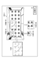
- the display screen shown in FIG. 8 includes an entire image 100-1 including an enlarged image 150B-1 synthesized by projective transformation, an enlarged image 150B requested to execute analysis, a “switch” button 41 as a software button, and the like. It is displayed.
- the display control unit 25 selects the entire image 100-1 including the enlarged image 150B-1 and the original entire image 100 before the enlarged image 150B-1 is synthesized (FIG. 4). Are alternately switched and displayed on the display unit 26.
- the user causes the “switch” button 41 to alternately display the entire image 100-1 including the enlarged image 150B-1 (enlarged image 150B-1) and the original entire image 100 (candidate image 150B-2).
- the “switch” button 41 By comparing the images, it is possible to confirm whether or not the enlarged image 150B-1 and the candidate image 150B-2 are images of the same area of the floor slab.
- the enlarged image 150B-1 and the candidate image 150B-2 are displayed with the same size and the same outer shape. Thereby, the user can easily visually confirm whether or not the enlarged image 150B-1 and the candidate image 150B-2 are images of the same area of the floor slab. That is, it can be confirmed whether or not the collation processing unit 54 of the image processing server 10 appropriately collates the entire image and the enlarged image (detects a local feature amount).
- the search for the enlarged image by the matching processing unit 54 has failed (the candidate image is incorrect )become. That is, the conversion parameter of the projection conversion formula calculated by the matching processing unit 54 is incorrect.
- the user notifies the image processing server 10 that the search for the enlarged image has failed, and the position of the image corresponding to the enlarged image on the whole image 100 displayed on the display unit 26 is indicated by the pointing device.
- the designated position is notified to the image processing server 10 as the position information of the image corresponding to the enlarged image.
- the image processing server 10 includes a position information receiving unit that receives position information of an image corresponding to the enlarged image on the entire image, and the matching processing unit 54 includes position information (for example, the entire image) received by the position information receiving unit. Based on the clicked position information received on the image), the collation range in the entire image is narrowed down and collation is re-executed. Also, when the enlarged image search by the matching processing unit 54 is impossible (when the candidate image is not found), the matching processing unit 54 can re-execute the matching as in the case of the enlarged image search failure.
- the display control unit 25 combines the entire image 100-1 obtained by combining the enlarged image 150B-1 obtained by projective transformation with the entire image 100 as shown in FIG. 100 is switched and displayed on the display screen of the display unit 26 in accordance with the operation of the “switch” button 41 so that both images can be compared.
- the display control unit 25 Does not provide the “switch” button 41, and displays the combined whole image 100-1 and the combined whole image 100 side by side on the display screen of the display unit 26.
- the user compares the entire image 100-1 after combining the enlarged image 150B-1 with the entire image 100 before combining (particularly, the enlarged image 150B-1 and the candidate image 150B-2 in the entire image 100). Confirmation of whether or not the images are of the same floor slab) can be performed more accurately.
- the collation processing unit 54 is common in that it detects a plurality of corresponding points having the same local feature amount between the entire image and the enlarged image. The difference is that a projective transformation formula (transformation parameter) for projective transformation of the candidate area corresponding to the enlarged image is calculated.
- the display control unit 25 of the user terminal 11 performs projective transformation on the image of the area corresponding to the enlarged image in the entire image based on the projective transformation formula having the transformation parameter received from the image processing server 10, and is shown in FIG. In this manner, the enlarged image 150B and the candidate image 150B-3 obtained by projective transformation of the image of the area corresponding to the enlarged image 150B in the entire image are displayed in a switchable manner (display processing step).
- FIG. 9 is a diagram showing another embodiment of the display screen of the display unit 26 for confirming the correspondence between the whole image and the enlarged image.
- the display screen shown in FIG. 9 includes an enlarged image 150B requested to be analyzed, a candidate image 150B-3 obtained by projective transformation of an image of an area corresponding to the enlarged image 150B in the entire image 100, an entire image 100, and software buttons.
- a “switch” button 41 and the like are displayed.
- the display control unit 25 alternately switches between the enlarged image 150B and the projective transformed candidate image 150B-3 and causes the display unit 26 to display them.
- the entire image 100 is also displayed on the display screen shown in FIG. 9, the enlarged image 150B or the candidate image 150B-3 obtained by the projective transformation and the image corresponding to the enlarged image 150B in the whole image 100 before the projective transformation are displayed. Can be compared. In this case, in the entire image 100, it is preferable that a frame indicating which region in the entire image 100 the projection-converted candidate image 150B-3 is superimposed on the entire image 100.
- the user alternately displays an enlarged image 150B requested to be analyzed by the “switch” button 41 and a candidate image 150B-3 obtained by projective transformation of an image of an area corresponding to the enlarged image 150B in the entire image 100.
- a candidate image 150B-3 obtained by projective transformation of an image of an area corresponding to the enlarged image 150B in the entire image 100.
- the enlarged image 150B and the candidate image 150B-3 are displayed with the same size and the same outer shape. Thereby, the user can easily visually confirm whether or not the enlarged image 150B and the candidate image 150B-3 are images of the same area of the floor slab.
- the search for the enlarged image by the matching processing unit 54 has failed (the candidate image is incorrect )become.
- the user notifies the image processing server 10 that the search for the enlarged image has failed, and the entire image 100 displayed on the display unit 26.
- the position of the image corresponding to the enlarged image is designated by the pointing device, the designated position is notified to the image processing server 10 as the position information of the image corresponding to the enlarged image, and the collation processing unit 54 is re-executed. Let it be done.
- the display control unit 25 displays the enlarged image 150B and the projective transformed candidate image 150B-3 as shown in FIG. 9 according to the operation of the “switch” button 41.
- the display control unit 25 does not provide the “switch” button 41 and the enlarged image 150B.
- the candidate images 150B-3 subjected to the projective transformation are displayed side by side on the display screen of the display unit 26.
- the user can compare the enlarged image 150B with the projective-converted candidate image 150B-3 (particularly confirm whether the enlarged image 150B and the projective-converted candidate image 150B-3 are images of the same floor slab. ) Can be performed more accurately.
- ⁇ Third embodiment of verification check> When the matching processing unit 54 detects a plurality of corresponding points whose local feature amounts coincide with the enlarged image 150B in each of a plurality of regions in the whole image 100 (that is, when a plurality of candidate images are detected), the whole image A conversion parameter for projective conversion of the enlarged image 150B with respect to 100 is calculated for each of a plurality of candidate images, and the calculated conversion parameters for each of the plurality of candidate images are returned to the user terminal 11.
- the display control unit 25 of the user terminal 11 performs projective conversion on each of the enlarged images 150 ⁇ / b> B based on a plurality of projective conversion formulas having conversion parameters for each of a plurality of candidate images received from the image processing server 10. Then, as shown in FIG. 10, the whole image 100-1 obtained by combining the enlarged images 150B-1A and 150B-1B obtained by projective transformation with the whole image 100 and the whole image 100 before composition are displayed in a switchable manner.
- FIG. 10 is a diagram illustrating an example of a display screen of the display unit 26 for confirming the correspondence between the entire image and the enlarged image. Regarding the case where two candidate images corresponding to the enlarged image exist in the entire image. Show.
- the enlarged images 150B-1A, 150B- in the original whole image 100 are used instead of the projection-transformed enlarged images 150B-1A, 150B-1B.
- Candidate images 150B-2A and 150B-2B corresponding to the 1B1 candidate area are displayed.
- a frame indicating a candidate area corresponding to is superimposed and displayed on the entire image 100.
- the entire image 100-1 including the enlarged images 150B-1A and 150B-1B it is preferable to display a frame indicating the area of the enlarged images 150B-1A and 150B-1B. This is to clarify in which region in the entire image 100 the enlarged images 150B-1A and 150B-1B are combined.
- the user selects the entire image 100-1 (enlarged images 150B-1A and 150B-1B) including the enlarged images 150B-1A and 150B-1B and the original entire image 100 (candidate images 150B-2A, 150B-2B) are alternately displayed and the two images are compared to determine whether the enlarged image 150B-1A and the candidate image 150B-2A are images of the same area of the floor slab, or the enlarged image 150B- It can be confirmed whether 1B and candidate images 150B-2B are images of the same area of the floor slab.
- the user selects one (correct) candidate image corresponding to the enlarged image from a plurality of candidate images (in this embodiment, two candidate images 150B-2A and 150B-2B), and selects the selection result as an image processing server. 10 is notified.
- the defect identification unit 55 of the image processing server 10 receives an analysis execution request for an enlarged image obtained by enlarging a defect (in this example, a crack) of the floor slab from the user terminal 11, the enlarged image is displayed.
- the crack is identified, and the raster data indicating the identified crack is thinned into vector data.
- labeling is performed for each crack, and the vector data of the crack can be managed by the labeling number.
- crack information including crack vector data is transmitted from the image processing server 10 to the user terminal 11. Not only the crack vector data, but also raster data indicating a crack image may be transmitted as defect information.
- the display control unit 25 of the user terminal 11 superimposes and displays the defect drawing line obtained by tracing the defect of the floor slab on the enlarged image and the entire image displayed on the display unit 26 based on the defect information received from the image processing server 10.
- FIGS. 11 to 14 are diagrams showing embodiments of confirmation and correction screens after image analysis of an enlarged image displayed on the display unit 26 of the user terminal 11, respectively.
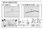
- the confirmation / correction screen shown in FIG. 11 functions as the first original enlarged image 150A requested to be analyzed, the enlarged image 150A-4 showing the analysis result, the entire image 100, and the defect information input unit and correction unit.
- Various icon buttons 42 to 47 and the like are displayed.
- a defect drawing line 30A-1 obtained by tracing a defect (crack) is superimposed and displayed.
- the defect drawing line 30A-1 is preferably a cracked image in which the cracked image is emphasized by brightness or color so as to be distinguishable from the cracked image 30A of the original enlarged image 150A, or is thickened based on vector data indicating the crack. .
- the user compares the original enlarged image 150A with the enlarged image 150A-4 on which the defect drawing line 30A-1 is displayed in a superimposed manner to determine whether or not the defect (crack) is properly identified by the defect identifying unit 55. Can be confirmed visually.
- defect drawing line defect information
- the automatically recognized cracks are interrupted in the middle, it is also possible to correct these cracks by joining them into a single crack.
- the user selects the icon button 43 indicating the eraser and manually operates the cursor (not shown) of the icon button 43. Then, the defect drawing line (defect information) is erased on the enlarged image 150A-4.
- defect information such as free lime, concrete peeling, and rebar exposure
- defect information such as free lime, concrete peeling, and rebar exposure
- the information confirmed and corrected as described above is transmitted to the image processing server 10.
- the second original enlarged image 150B, the enlarged image 150B-4 showing the analysis result, the entire image 100, the icon buttons 42 to 47, and the like are displayed on the confirmation and correction screen shown in FIG.
- the user confirms and corrects the analysis result for the second enlarged image 150B using the confirmation and correction screen shown in FIG. 12 in the same manner as the confirmation and correction of the analysis result for the first enlarged image 150A. Can do.
- a defect drawing line 30B-1 obtained by tracing the automatically recognized crack is superimposed and displayed on the enlarged image 150B-4 showing the analysis result of the original enlarged image 150B.
- the user confirms and corrects the analysis result for the third enlarged image 150C using the confirmation and correction screen shown in FIG. 13 in the same manner as the confirmation and correction of the analysis result for the first enlarged image 150A. Can do.
- a defect drawing line 30C-1 obtained by tracing the automatically recognized crack is superimposed and displayed on the enlarged image 150C-4 showing the analysis result of the original enlarged image 150C.
- the user confirms and corrects the analysis result for the fourth enlarged image 150D using the confirmation correction screen shown in FIG. 14 in the same manner as the confirmation and correction of the analysis result for the first enlarged image 150A. Can do.
- a defect drawing line 30D-1 obtained by tracing the automatically recognized crack is superimposed and displayed on the enlarged image 150D-4 showing the analysis result of the original enlarged image 150D.
- the “Next” button 44 is grayed out so as not to be operated.
- the user when taking an enlarged image including a floor slab defect, the user measures the width of the crack and the interval between adjacent cracks using a crack scale or the like, and records it in the field book. Then, using the confirmation / correction screen and the operation unit 23 shown in FIGS. 11 to 14, it is possible to input crack information indicating the width of the crack and the interval between adjacent cracks while referring to the field book.
- the display control unit 25 of the user terminal 11 causes the display unit 26 to display the width of the crack and the interval between adjacent cracks based on the crack information input by the operation unit 23. Further, the crack information input at the user terminal 11 is transmitted to the image processing server 10.
- the conversion unit 56 shown in FIG. 6 is a part that performs geometric conversion (projection conversion) on the defect drawing line superimposed on the whole image, and the whole image 100 shown in FIG. 15 is input to the conversion unit 56.
- the entire image 100 is accompanied by information on defect drawing lines that have been confirmed and corrected.
- the entire image 100 (or a plurality of divided images) is uploaded from the user terminal 11, the entire image 100 is specified as an image corresponding to any of the floor plan drawings 200. . Further, the rectangular gap image 120 in the entire image 100 can be grasped by performing image analysis on the entire image 100.
- the conversion unit 56 sets four points at the four corners of the rectangular gap image 120 and four points at the four corners corresponding to the drawing 200 as corresponding points, and the gap image 120 corresponds to the drawing 200.
- a conversion parameter for performing geometric conversion (projective conversion) between the cases is calculated, and the defect drawing line in the case image 120 is projectively converted by a projective conversion formula having the calculated conversion parameter.
- the image processing server 10 transmits to the user terminal 11 data indicating the defect drawing line that has undergone projective conversion by the conversion unit 56.
- the user terminal 11 includes a data output unit (input / output interface 22) that outputs data indicating a defect drawing line that has been projectively transformed so as to correspond to floor plan drawing data in association with the drawing data.
- a data output unit input / output interface 22
- outputs data indicating a defect drawing line that has been projectively transformed so as to correspond to floor plan drawing data in association with the drawing data.
- the image processing server 10 includes a determination unit that determines a progress level of cracks in the floor slab based on crack information (a width of cracks and an interval between adjacent cracks) input from the user terminal 11, and the progress level of the cracks is determined by the user terminal.
- the display control unit 25 of the user terminal 11 preferably classifies and displays the defect drawing lines indicating the cracks according to the progress level of the cracks input from the image processing server 10. Further, the display control unit 25 of the user terminal 11 may classify and display defect drawing lines indicating cracks according to the crack width. For example, a range of crack width (crack width of 2 mm or more) is displayed. By designating, it is possible to selectively display a defect drawing line having a designated crack width.
- the image processing apparatus is configured by the image processing server and the user terminal.
- the present invention is not limited thereto, and the image processing apparatus may be realized by an independent apparatus without using a network or the like.
Landscapes
- Physics & Mathematics (AREA)
- General Physics & Mathematics (AREA)
- General Health & Medical Sciences (AREA)
- Chemical & Material Sciences (AREA)
- Analytical Chemistry (AREA)
- Biochemistry (AREA)
- Life Sciences & Earth Sciences (AREA)
- Health & Medical Sciences (AREA)
- Immunology (AREA)
- Pathology (AREA)
- Engineering & Computer Science (AREA)
- Theoretical Computer Science (AREA)
- Investigating Materials By The Use Of Optical Means Adapted For Particular Applications (AREA)
- Image Analysis (AREA)
- Image Processing (AREA)
Abstract
橋梁等の構造物の所定範囲を示す全体画像と全体画像の一部の拡大画像との照合の確認をユーザが簡便に行うことができる画像処理装置及び画像処理方法を提供する。画像処理装置を構成する画像処理サーバ(10)は、床版の1つの格間を含む全体画像と、格間内の欠陥を拡大して撮影された拡大画像とを取得し、照合処理部は、全体画像と拡大画像とを照合し、全体画像に対して拡大画像を射影変換する変換パラメータを算出する。ユーザ端末は、画像処理サーバ(10)から変換パラメータを取得し、ユーザ端末の表示制御部は、変換パラメータを有する射影変換式により射影変換された拡大画像(150B-1)と、全体画像内の拡大画像の候補領域に対応する候補画像(150B-2)とを比較可能に表示部に表示させる。
Description
本発明は画像処理装置及び画像処理方法に係り、特に橋梁等の構造物の全体画像と全体画像の一部の拡大画像とを容易に比較可能にする技術に関する。
橋梁等の社会インフラ構造物は、定期的に点検を行う必要がある。また、構造物の点検を効率的に行うために、構造物を撮影した画像を処理することにより欠陥(ひび割れ欠陥)を自動的に検出するひび割れ欠陥検出方法が提案されている(特許文献1)。
特許文献1に記載のひび割れ欠陥検出方法は、構造物の所定範囲を全体的に撮影した全体画像から、カメラの焦点距離及び構造物の既知寸法に基づいて、正射影変換された全体画像を取得し、全体画像の撮影位置と同一位置を基点としてカメラを回転させ、構造物の所定範囲を分割し且つ拡大して撮影した部分画像を取得し、更に部分画像の撮影範囲内のひび割れ欠陥が識別可能となるように十分に拡大して撮影した拡大画像を取得する。
正射影変換された全体画像と部分画像とを照合することにより、全体画像と部分画像との位置関係及び正射影変換した部分画像を求め、正射影変換された部分画像と拡大画像とを照合することにより、部分画像と拡大画像との位置関係及び正射影変換した拡大画像を求める。
そして、正射影変換された拡大画像を用いてひび割れ欠陥を検出するようにしている。これにより、構造物を正面から撮影できないような条件下においても、正射影変換された拡大画像を用いて、正確なひび割れ欠陥を検出できるようにしている。また、正射影変換された全体画像と正射影変換された部分画像との位置関係が求められ、かつ正射影変換された部分画像と正射影変換された拡大画像との位置関係が求められているため、拡大画像から検出されたひび割れ欠陥の、全体画像(構造物)に対する位置も特定できるようにしている。
特許文献1に記載のひび割れ欠陥検出方法は、構造物の所定範囲を撮影した全体画像を正射影変換するために、建造物の所定範囲内に寸法が既知である矩形部位が存在する建造物が点検対象となっており、建造物の所定範囲内に存在する矩形部位の寸法を取得する必要がある。
また、特許文献1には、正射影変換された全体画像と、全体画像の撮影位置と同一位置を基点としてカメラを回転させ、構造物の所定範囲を分割し且つ拡大して撮影した部分画像とを照合することにより、相互の位置関係を求める記載があるが、全体画像と部分画像との具体的な照合方法に関する記載がない。
同様に、特許文献1には、正射影変換された部分画像と拡大画像とを照合することにより、相互の位置関係を求める記載があるが、部分画像と拡大画像との具体的な照合方法に関する記載がない。
更に特許文献1には、全体画像と部分画像との照合、又は部分画像と拡大画像との照合に誤りが発生する場合の対策に関する記載がない。全体画像と部分画像との照合、又は部分画像と拡大画像との照合に誤りが発生すると、画像間の相互の位置関係も誤り、その結果、ひび割れ欠陥が検出された位置(構造物の所定範囲におけるひび割れ欠陥の位置)を誤るという問題がある。
本発明はこのような事情に鑑みてなされたもので、橋梁等の構造物の所定範囲を示す全体画像と全体画像の一部の拡大画像との照合結果の確認をユーザが簡便に行うことができる画像処理装置及び画像処理方法を提供することを目的とする。
上記目的を達成するために本発明の一の態様に係る画像処理装置は、構造物の所定範囲を示す全体画像を取得する第1の画像取得部と、所定範囲内における構造物の欠陥を拡大して撮影された拡大画像を取得する第2の画像取得部と、全体画像と拡大画像とを照合し、全体画像内における拡大画像の領域に関連する位置関係情報を算出する照合処理部と、拡大画像と、位置関係情報に基づいて特定される全体画像内の拡大画像の候補領域に対応する候補画像とを比較可能に表示部に表示させる表示制御部と、を備える。
本発明の一の態様によれば、全体画像と拡大画像とを照合し、全体画像内における拡大画像の領域に関連する位置関係情報を算出する。表示制御部は、拡大画像と、位置関係情報に基づいて特定される全体画像内の拡大画像の候補領域に対応する候補画像とを比較可能に表示部に表示させる。ユーザは、表示部に比較可能に表示された拡大画像と全体画像内の拡大画像の候補領域に対応する候補画像とを目視で確認することで、全体画像と拡大画像との照合結果の適否を確認することができる。尚、全体画像と拡大画像との照合が適切に行われている場合には、全体画像内における拡大画像の領域に関連する位置関係情報も誤りなく算出することができる。
本発明の他の態様に係る画像処理装置において、照合処理部は、全体画像及び拡大画像からそれぞれ特徴量が一致する複数の対応点を検出し、検出した複数の対応点に基づいて拡大画像又は全体画像を幾何変換する変換パラメータを位置関係情報として算出することが好ましい。
本発明の更に他の態様に係る画像処理装置において、表示制御部は、変換パラメータに基づいて幾何変換した拡大画像を、全体画像内の拡大画像に対応する候補領域に合成した全体画像と、合成前の全体画像とを表示部に切り替えて表示させることが好ましい。変換パラメータに基づいて幾何変換した拡大画像は、全体画像内の拡大画像に対応する候補領域の画像と同じ形状及び同じサイズになる。そして、幾何変換した拡大画像を全体画像内の拡大画像に対応する候補領域に合成した全体画像と、合成前の全体画像とを表示部に切り替えて表示させることにより、両画像を容易に比較することができる。
本発明の更に他の態様に係る画像処理装置において、表示制御部は、変換パラメータに基づいて幾何変換した拡大画像を、全体画像内の拡大画像に対応する候補領域に合成した全体画像と、合成前の全体画像とを表示部に並べて表示させることが好ましい。幾何変換した拡大画像を全体画像内の拡大画像に対応する候補領域に合成した全体画像と、合成前の全体画像とを表示部に並べて表示させることにより、両画像を容易に比較することができる。
本発明の更に他の態様に係る画像処理装置において、表示制御部は、拡大画像と、全体画像内の拡大画像に対応する候補領域の候補画像を、変換パラメータに基づいて幾何変換した変換画像とを表示部に切り替えて表示させることが好ましい。全体画像内の拡大画像に対応する候補領域の候補画像を、変換パラメータに基づいて幾何変換した変換画像は、拡大画像と同じ形状及び同じサイズになる。そして、拡大画像と全体画像内の拡大画像に対応する候補領域の候補画像を幾何変換した変換画像とを表示部に切り替えて表示させることにより、両画像を容易に比較することができる。
本発明の更に他の態様に係る画像処理装置において、表示制御部は、拡大画像と、全体画像内の拡大画像に対応する候補領域の候補画像を、変換パラメータに基づいて幾何変換した変換画像とを表示部に並べて表示させることが好ましい。拡大画像と、全体画像内の拡大画像に対応する候補領域の候補画像を幾何変換した変換画像とを表示部に並べて表示させることにより、両画像を容易に比較することができる。
本発明の更に他の態様に係る画像処理装置において、拡大画像上での構造物の欠陥の位置及び形状を含む欠陥情報を入力する欠陥情報入力部を備え、表示制御部は、欠陥情報に基づいて構造物の欠陥をトレースした欠陥描画線を、表示部に表示した拡大画像及び全体画像に重畳表示させることが好ましい。これにより、拡大画像上及び全体画像上で、構造物の欠陥を容易に視認することができる。
本発明の更に他の態様に係る画像処理装置において、拡大画像を画像解析し、構造物の欠陥を識別する欠陥識別部を備え、欠陥情報入力部は、欠陥識別部から欠陥情報を入力することが好ましい。これにより、欠陥情報を自動的に入力することができる。
本発明の更に他の態様に係る画像処理装置において、欠陥情報入力部は、拡大画像上での構造物の欠陥の位置及び形状を手動で指示するポインティングデバイスを含むことが好ましい。これにより、欠陥情報を手動で入力することができる。
本発明の更に他の態様に係る画像処理装置において、重畳表示された欠陥情報を手動で修正する修正部を備えることが好ましい。これにより、欠陥識別部から入力した欠陥情報に誤りがあった場合、又はポインティングデバイスによる欠陥情報の指示に誤りがあった場合に、その欠陥情報を修正することができる。
本発明の更に他の態様に係る画像処理装置において、構造物の図面データを記憶する記憶部と、構造物の所定範囲を図面データの対応する範囲に一致させる幾何変換を行う変換部であって、全体画像に重畳表示された欠陥描画線のみを幾何変換する変換部と、図面データに関連付けて幾何変換した欠陥描画線を示すデータを出力するデータ出力部と、を備えることが好ましい。これにより、欠陥描画線が描画された図面データを取得することができる。
本発明の更に他の態様に係る画像処理装置において、構造物の欠陥は、ひび割れであり、欠陥識別部は、拡大画像から構造物のひび割れを示すひび割れ画像を抽出し、表示制御部は、ひび割れ画像を輝度又は色により強調した欠陥描画線を生成することが好ましい。
本発明の更に他の態様に係る画像処理装置において、構造物の欠陥は、ひび割れであり、表示制御部は、ひび割れを示す欠陥描画線と、ひび割れの幅及び隣接するひび割れ間の間隔を示すひび割れ情報とを表示部に表示させることが好ましい。
本発明の更に他の態様に係る画像処理装置において、構造物の欠陥は、ひび割れであり、表示制御部は、ひび割れを示す欠陥描画線を、ひび割れの幅に応じて分類して表示させることが好ましい。例えば、ひび割れの幅ごとに分類して(色分けし、又は表示するひび割れ幅を選択して)欠陥描画線を表示する。
本発明の更に他の態様に係る画像処理装置において、構造物の欠陥は、ひび割れであり、ひび割れの幅及び隣接するひび割れ間の間隔を示すひび割れ情報に基づいてひび割れの進捗レベルを判別する判別部を備え、表示制御部は、ひび割れを示す欠陥描画線を、判別されたひび割れの進捗レベルに応じて分類して表示させることが好ましい。構造物のひび割れの進捗レベルは、ひび割れの幅及び隣接するひび割れ間の間隔により判定可能であり、判別部は、ひび割れの幅及び隣接するひび割れ間の間隔を示すひび割れ情報に基づいてひび割れの進捗レベルを判別し、表示制御部は、判別されたひび割れの進捗レベルに応じて、ひび割れを示す欠陥描画線を分類して(例えば、色分けして)表示させる。
本発明の更に他の態様に係る画像処理装置において、表示制御部は、全体画像内の拡大画像に対応する候補領域を示す枠を表示部に表示させることが好ましい。これにより、拡大画像と全体画像内の拡大画像の候補領域に対応する候補画像とを更に比較可能に表示させることができる。
本発明の更に他の態様に係る画像処理装置において、第2の画像取得部が複数の拡大画像を取得すると、照合処理部は、全体画像と複数の拡大画像とを照合し、全体画像内における複数の拡大画像の候補領域に関連する複数の位置関係情報をそれぞれ算出し、表示制御部は、複数の拡大画像のうちから選択された1の拡大画像と、選択された1の拡大画像に対応する位置関係情報に基づいて特定される全体画像内の選択された1の拡大画像の候補領域に対応する候補画像とを比較可能に表示部に表示させることが好ましい。これにより、複数の拡大画像が取得された場合でも、1枚ずつ選択された拡大画像と全体画像内の選択された拡大画像の候補領域に対応する候補画像とを比較可能に表示することができる。
本発明の更に他の態様に係る画像処理装置において、照合処理部は、全体画像と拡大画像とを照合し、全体画像内における拡大画像を示す複数の候補領域を検出すると、複数の候補領域に関連する複数の位置関係情報をそれぞれ算出し、表示制御部は、拡大画像と、複数の位置関係情報に基づいて特定される全体画像内の拡大画像の複数の候補領域に対応する複数の候補画像とを比較可能に表示部に表示し、表示部に表示された複数の候補領域に対応する複数の候補画像のうちの1の候補画像の選択を受け付ける画像選択部を備えることが好ましい。全体画像と拡大画像とを照合した結果、全体画像内における拡大画像を示す複数の候補領域が検出された場合、拡大画像と全体画像内の拡大画像の複数の候補領域に対応する複数の候補画像とを比較可能に表示する。そして、画像選択部により複数の候補画像のうちの1の候補画像の選択を受け付けることにより、全体画像内の拡大画像に対応する領域をユーザにより選択させることができる。
本発明の更に他の態様に係る画像処理装置において、照合処理部により算出された位置関係情報が不正解の場合、又は位置関係情報を算出することができない場合、表示部に表示された全体画像上で、拡大画像に対応する画像の位置情報を受け付ける位置情報受付部を備え、照合処理部は、位置情報受付部により受け付けた位置情報を元に全体画像と拡大画像との照合を再実行することが好ましい。照合処理部は、位置情報受付部が受け付けた拡大画像に対応する画像の位置情報(例えば、全体画像上で受け付けたクリックした位置情報)を元に、全体画像における照合範囲を絞り込んで再照合することができる。
本発明の更に他の態様に係る画像処理装置において、構造物は橋梁の床版であり、所定範囲は床版の格間であり、第1の画像取得部は、撮像装置により撮影された1つの格間を含む床版画像を全体画像として取得することが好ましい。橋梁の床版の点検は、格間ごとに行われるためである。
本発明の更に他の態様に係る画像処理装置において、第1の画像取得部は、撮像装置により格間を複数回に分割して撮影された複数の分割画像を取得し、取得した複数の分割画像を合成して床版画像を生成し、生成した床版画像を全体画像として取得することが好ましい。1つの格間を含む床版画像(全体画像)は、少なくとも拡大画像との照合が可能な解像で撮影する必要があるが、格間の大きさによっては1回の撮影では、1つの格間を含む床版画像を撮影できない場合がある。この場合には、格間を複数回に分割して撮影し、複数の分割画像を取得する。そして、取得した複数の分割画像を合成して床版画像を生成する。
本発明の更に他の態様に係る画像処理方法は、構造物の所定範囲を示す全体画像を取得する第1の画像取得工程と、所定範囲内における構造物の欠陥を拡大して撮影された拡大画像を取得する第2の画像取得工程と、全体画像と拡大画像とを照合し、全体画像内における拡大画像の領域に関連する位置関係情報を算出する照合処理工程と、拡大画像と、位置関係情報に基づいて特定される全体画像内の拡大画像の候補領域に対応する候補画像とを比較可能に表示部に表示させる表示制御工程と、を含む。
本発明によれば、橋梁等の構造物の所定範囲を示す全体画像と全体画像の一部の拡大画像とを照合し、全体画像内における拡大画像の領域に関連する位置関係情報を算出し、拡大画像と、位置関係情報に基づいて特定される全体画像内の拡大画像の候補領域に対応する候補画像とを比較可能に表示部に表示させるようにしたため、ユーザは、表示部に比較可能に表示された拡大画像と全体画像内の拡大画像の候補領域に対応する候補画像とを目視で確認することができ、全体画像と拡大画像との照合結果の適否を確認することができる。
以下、添付図面に従って本発明に係る画像処理装置及び画像処理方法の実施の形態について説明する。
[画像処理装置]
図1は本発明に係る画像処理装置の概念図である。本実施形態に係る画像処理装置1は、ユーザ端末11と、インターネット等のネットワーク12を介して各ユーザ端末11に接続される画像処理サーバ10とを備える。
図1は本発明に係る画像処理装置の概念図である。本実施形態に係る画像処理装置1は、ユーザ端末11と、インターネット等のネットワーク12を介して各ユーザ端末11に接続される画像処理サーバ10とを備える。
ユーザ端末11は、ユーザが構造物の点検調書等を作成する際に操作する端末であり、例えば、パーソナルコンピュータ、タブレットデバイス等のポータブル端末などの形態をとりうる。
本例の点検対象の構造物は、橋梁であり、特に橋梁を構成する床版を点検対象とする場合について説明する。
橋梁は、橋台や橋脚の間に渡された主桁と、橋梁の長手方向に設けられた主桁と直交する方向に設けられ、主桁間を連結する横桁と、風、地震等の横荷重に抵抗するために主桁を相互に連結する対傾構及び横構とを含む各種の部材から構成され、主桁等の上部には、車輌等が走行するための床版が打設されている。床版は、鉄筋コンクリート製のものが一般的である。
床版は、通常、主桁と横桁とにより画成された矩形形状の格間が基本単位となっており、床版の損傷(ひび割れ、遊離石灰、コンクリートの剥離、及び鉄筋露出等)を点検する場合、格間単位で行われる。
画像処理サーバ10は、ユーザ端末11から送られてくる点検対象の構造物(橋梁の床版)を撮影した画像及び指示等に応じて、ユーザが点検調書を作成する際に必要な情報を生成し、生成した情報をユーザ端末11に返す。
<ユーザ端末11>
この画像処理装置1において、まずユーザ端末11の機能構成について説明する。
この画像処理装置1において、まずユーザ端末11の機能構成について説明する。
図2はユーザ端末11の機能構成例を示すブロック図である。
本例のユーザ端末11は、主として端末通信部21、入出力インターフェース22、操作部23、記憶部24、表示制御部25、表示部26及び端末制御部27から構成されている。
端末通信部21は、ネットワーク12(図1参照)を介して床版を撮影した画像及び画像の解析実行等の指示を画像処理サーバ10に送信し、また、画像処理サーバ10により画像解析された解析結果等を画像処理サーバ10からネットワーク12を介して受信する通信部である。
入出力インターフェース22は、無線又は有線により外部機器との間で情報のやり取りを行う部分であり、本例では、デジタルカメラ(撮像装置)20により撮影された床版の画像をデジタルカメラ20から無線通信により入力する。
図3は、床版を含む橋梁を撮影した画像の一例を示す図であり、特に床版の1つの格間を複数回に分割して撮影した複数の分割画像に関して示している。
図3に示す複数(3枚)の分割画像100A、100B及び100Cは、後述するように画像処理サーバ10により1枚の画像に合成される合成用の画像である。この1枚の画像は、床版の1つの格間を含む画像であり、以下、構造物の所定範囲(床版の1つの格間に対応する範囲)を示す「全体画像100(図4)」という。
分割画像100A、100B及び100Cは、隣接する分割画像間で重複する重複領域を含む必要があり、適切に合成するためには重複領域は、各分割画像の全領域の30%程度有することが好ましい。即ち、撮影者は、デジタルカメラ20により床版の1つの格間を複数回に分割して撮影する場合には、隣接する分割画像間で30%程度重複するように画角を決定して撮影することが好ましい。
図4において、全体画像100には、主桁の一部を示す画像102、104と、横桁の一部を示す画像112、114と、床版の一部(主桁と横桁とにより画成された1つの格間)の画像(格間画像)120とが含まれている。
尚、本例の全体画像100は、3枚の分割画像100A、100B及び100Cを合成して生成された画像であるが、例えば、格間のサイズが小さく、デジタルカメラ20による1回の撮影で1つの格間を含む床版の画像(全体画像)を、適当な解像度で撮影することができる場合には、1回の撮影により取得した画像でもよい。
また、デジタルカメラ20は、例えば、5000×4000画素程度の画素数を有する汎用のコンパクトデジタルカメラでよい。
図5は、床版の所定範囲(格間)内の欠陥を拡大して撮影した拡大画像の一例を示す図であり、特に床版の欠陥の一つであるひび割れを拡大して撮影した複数の拡大画像に関して示している。
図5に示す複数(4枚)の拡大画像150A、150B、150C及び150Dは、床版の欠陥の一つであるひび割れ(ひび割れの幅、長さ等)を画像解析により識別可能な解像度で撮影されたものである。尚、図5において、符号30A、30B、30C、30Dは、それぞれ床版に発生したひび割れを示すひび割れ画像である。尚、ひび割れ画像30Bは2本のひび割れを示し、ひび割れ画像30C,30Dはそれぞれ一本のひび割れの一部を示している。
拡大画像は、画像解析により識別する必要があるひび割れの最小幅に応じて拡大画像の解像度を決定する必要があり、例えば0.1mmのひび割れ幅を画像解析により識別する必要がある場合、拡大画像は、0.1mmのひび割れ幅を識別できる解像度以上で撮影する必要がある。
また、デジタルカメラ20により欠陥を拡大した拡大画像を撮影する場合、デジタルカメラ20の光学ズームのズーム倍率を高くして撮影する方法、床版に近づいて撮影する方法、及びこれらの方法を組み合わせて撮影する方法がある。また、拡大画像を撮影する場合には、床版に正対して撮影することが好ましい。
図2に戻って、デジタルカメラ20により撮影された床版の画像(図3に示した合成用の分割画像、図5に示した拡大画像)は、デジタルカメラ20から入出力インターフェース22を介してユーザ端末11に取り込まれ、記憶部24に保存される。
操作部23は、マウス、表示部26がタッチパネルを有する場合にはそのタッチパネル等を含むポインティングデバイス、及びキーボードを含み、表示部26の画面に表示されるポインタやアイコンを操作するために使用されるとともに、拡大画像上での構造物の欠陥の位置及び形状を含む欠陥情報を入力する欠陥情報入力部、欠陥情報を手動で修正する修正部、ひび割れの幅及び隣接するひび割れ間の間隔を示すひび割れ情報等のテキスト情報を入力するテキスト情報入力部として機能する。
記憶部24には、入出力インターフェース22を介して入力した床版の画像が記憶されるとともに、本例ではユーザ端末11が、本発明に係る画像処理装置の一部として機能するための専用のソフトウェアが格納され、更に後述する欠陥描画線を示すデータが記憶される。
端末制御部27は、操作部23からの入力に応じて記憶部24に格納されたソフトウェアを実行し、ユーザ端末11の各部を統括制御する部分である。
表示制御部25は、端末制御部27から入力する画像を含む各種のデータ及び指令に基づいて表示部26に表示させる表示画面全般を制御する。表示制御部25は、主として構造物(床版)の欠陥を拡大して撮影された拡大画像と、構造物の所定範囲(床版の格間)を示す全体画像内の拡大画像の候補領域に対応する候補画像とを比較可能に表示部26に表示させる(表示制御工程)。尚、表示制御部25により表示部26に表示させる各種の表示画面の詳細については後述する。
<画像処理サーバ10>
次に、画像処理装置1を構成する画像処理サーバ10機能構成について説明する。
次に、画像処理装置1を構成する画像処理サーバ10機能構成について説明する。
図6は画像処理サーバ10の機能構成例を示すブロック図である。
本例の画像処理サーバ10は、主としてサーバ通信部51、画像の記憶部として機能する画像DB(DB:database)52、構造物の図面データを記憶する図面DB53、照合処理部54、欠陥識別部55、変換部56、及びサーバ制御部57から構成されている。
画像DB52及び図面DB53は、1又は複数のハードディスク装置を含んで構成される。照合処理部54、欠陥識別部55、変換部56、及びサーバ制御部57は、1又は複数のCPU(Central Processing Unit)と、CPUのワーキングメモリと、ハードディスク装置等に記憶され、メモリ上に展開された画像処理プログラムとにより構成され、CPUが画像処理プログラムを実行することにより各部の機能を担う。
サーバ通信部51は、ユーザ端末11からネットワーク12(図1参照)を介して床版の画像及び画像の解析実行等の指示を受信し、また、画像処理サーバ10により画像解析された解析結果等をネットワーク12を介してユーザ端末11に送信する通信部である。
画像DB52は、ユーザ端末11からサーバ通信部51を介して受信した画像(分割画像、全体画像、拡大画像等)を、サーバ制御部57による制御の元で記憶する記憶部であり、床版の格間単位で、複数の分割画像(又は全体画像)と、1乃至複数の拡大画像とを関連付けて記憶する。
図面DB53は、構造物の図面データを記憶する記憶部であり、複数の橋梁(床版を含む)の図面データ(CAD(computer-aided design)図)を保存及び管理する。図面DB53には、橋梁の最初の点検時にユーザ端末11から送信された図面データが保存されるが、図面データの保存方法はこれに限定されない。
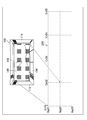
図15には、1つの格間を示す格間画像120を含む全体画像100と、点線で示した床版の図面200とが示されている。これらの全体画像100及び図面200は、ユーザ端末11の表示部26に表示させることが可能である。尚、床版の図面200は、図面DB53に格納された図面データに基づいて表示部26に表示させることができる。
図15に示す床版の図面200は、3つの主桁と5つの横桁とに対応する図面である。Mg01~Mg03は、それぞれ主桁(Mg:Main girder)の部材番号であり、Cr01~Cr05は、それぞれ横桁(Cr:Cross beam)の部材番号である。尚、1画面に橋梁の床版全体の図面を適切に表示することができない場合(橋梁の全長が長い場合)には、床版の一部の図面を表示し、床版の図面をスクロールできるようにすることが好ましい。
ユーザ端末11から画像処理サーバ10に床版の画像をアップロードする場合、ユーザは、点検対象の橋梁(床版)を特定する情報を画像処理サーバ10に送信し、画像処理サーバ10から床版の図面データを取得する。画像処理サーバ10は、ユーザ端末11から床版を特定する情報を取得すると、図面DB53から対応する図面データを読み出し、読み出した図面データをユーザ端末11に送信することができる。
ユーザ端末11の表示制御部25は、画像処理サーバ10から取得した図面データに基づいて表示部26に床版の図面200(図15)を表示させるとともに、記憶部24に記憶させた床版の画像(合成用の分割画像、全体画像、拡大画像)の一覧を表示させる。
ユーザは、床版の図面200内の1つの格間を特定し、その格間に対応する合成用の複数の分割画像又は全体画像を特定した格間にドラックアンドドロップし、床版の格間と複数の分割画像又は全体画像との関連付けを行う。同様に、拡大画像を特定した格間にドラックアンドドロップし、床版の格間と拡大画像との関連付けを行う。
尚、記憶部24において、格間毎に床版の画像がフォルダにより管理されている場合には、図面200内の1つの格間を特定し、その格間に対応するフォルダを特定した格間にドラックアンドドロップし、床版の格間と格間毎の画像とを関連付けるようにしてもよい。また、合成用の複数の分割画像を画像処理サーバ10にアップロードする場合、図3に示すように複数の分割画像100A、100B、100Cの格間内の位置関係を特定してアップロードすることが好ましい。画像処理サーバ10において、複数の分割画像100A、100B、100Cから1枚の全体画像100を合成する合成処理の演算負荷を軽減するためである。
上記のように床版の格間に関連付けられた格間毎の合成用の複数の分割画像又は全体画像は、ユーザ端末11の端末通信部21からネットワーク12及びサーバ通信部51を介して画像処理サーバ10に取得され、サーバ制御部57による制御の元で画像DB52に保存される。ここで、サーバ通信部51、サーバ制御部57及び画像DB52は、床版の格間を示す全体画像(合成用の複数の分割画像を含む)を取得する第1の画像取得部として機能し、この第1の画像取得部は、床版の格間を示す全体画像を取得する(第1の画像取得工程)。
また、床版の格間に関連付けられた格間毎の拡大画像は、ユーザ端末11の端末通信部21からネットワーク12及びサーバ通信部51を介して画像処理サーバ10に取得され、サーバ制御部57による制御の元で画像DB52に保存される。ここで、サーバ通信部51、サーバ制御部57及び画像DB52は、拡大画像を取得する第2の画像取得部として機能し、この第2の画像取得部は、床版の格間内の欠陥を拡大して撮影した拡大画像を取得する(第2の画像取得工程)。
次に、画像処理サーバ10が合成用の複数の分割画像を取得した場合について説明する。
この場合、第1の画像取得部の一部として機能するサーバ制御部57は、画像DB52から合成用の複数の分割画像を読み出し、これらの複数の分割画像を合成し、床版の1つの格間を含む床版画像を生成し、生成した床版画像を全体画像として取得する。
いま、合成用の複数の分割画像として、図3に示す3枚の分割画像100A、100B及び100Cを取得した場合について説明する。
3枚の分割画像100A、100B及び100Cは、床版の1つの格間を3回に分割して撮影された画像であり、それぞれデジタルカメラ20による撮影方向及び撮影位置等が異なっているが、隣接する分割画像間(分割画像100Aと分割画像100B、及び分割画像100Bと分割画像100C)には、互いに重複する重複領域を含んでいる。
サーバ制御部57は、隣接する分割画像間の互いに重複する重複領域からそれぞれ特徴量(局所特徴量)が一致する複数の対応点を検出する。
画像間の拡大縮小、回転及び照明変化等に強いロバストな局所特徴量として、SIFT (Scale-invariant feature transform)特徴量、SURF (Speed-Upped Robust Feature)特徴量、及びAKAZE (Accelerated KAZE)特徴量が知られている。
特徴量が一致する対応点の数(セット数)は、2つの画像のうちの一方の画像を幾何変換するために使用する変換パラメータの算出に必要な数以上検出する必要があり、例えば、幾何変換として射影変換を適用する場合には、4つの対応点を検出する。
射影変換式は、次式の通りである。

射影変換の変換パラメータは、[数1]式中のa、b、s、c、d、t、p、qの8個のパラメータを指す。また、(x,y)、(X,Y)は、それぞれ射影変換前後の座標値を示す。
従って、4つの対応点の座標値をそれぞれ[数1]式に代入した8つの連立方程式を立て、8つの連立方程式を解くことにより、射影変換に使用する8個の変換パラメータを算出することができる。
ここで、分割画像100Aを基準の画像とすると、分割画像100Aを基準とした場合の、分割画像100Bを射影変換する変換パラメータを算出し、算出した変換パラメータを有する射影変換式を使用して分割画像100Bを射影変換し、分割画像100Aと射影変換した分割画像100Bとを合成する。同様に、射影変換した分割画像100Bを基準とした場合の、分割画像100Cを射影変換する変換パラメータを算出し、算出した変換パラメータを有する射影変換式を使用して分割画像100Cを射影変換し、射影変換して合成した分割画像100Bと射影変換した分割画像100Cとを合成する。
図4は、図3に示した3枚の分割画像100A、100B及び100Cを上記のようにして合成することにより生成された全体画像100を示す図である。この全体画像100は、画像DB52に保存され、また、ユーザ端末11に送信されてユーザ端末11の記憶部24に保存される。
図7は、ユーザ端末11の表示部26に表示された複数の拡大画像を含む表示画面の一実施形態を示す図である。
図7に示す表示部26の表示画面には、ひび割れが拡大して撮影された4枚の拡大画像150A、150B、150C及び150Dと、ソフトウェアボタンである「解析実行」ボタン40が表示されている。
ユーザは、拡大画像の解析を画像処理サーバ10に依頼する場合、ユーザ端末11の表示部26の画面上で解析対象の拡大画像を、マウス等のポインティングデバイス(画像選択部)により選択し、「解析実行」ボタン40を押下する。画像処理サーバ10は、ユーザ端末11から拡大画像の選択指示及び解析実行のリクエストを受け付けると、アップロードされて画像DB52に登録された画像群から選択指示された拡大画像を読み出し、読み出した拡大画像から各種の欠陥(本例では、ひび割れ)の検出等の処理を行う。
図6に戻って、照合処理部54は、1つの格間を含む床版の画像(全体画像)と格間内の欠陥を拡大して撮影した拡大画像とを照合し、全体画像内における拡大画像の領域に関連する位置関係情報を算出する部分である。
いま、拡大画像150Bが選択され、拡大画像150Bに対する解析実行のリクエストを受け付けると、照合処理部54は、全体画像100(図4)と拡大画像150B(図7)とを照合し、拡大画像150Bが全体画像100のどの部分の拡大画像であるかを求める。
照合処理部54による全体画像100と拡大画像150Bとの照合は、画像間の拡大縮小及び回転に依存しない特徴量(前述したSIFT特徴量、又はSURF特徴量)の抽出により行う。具体的には、照合処理部54は、全体画像100と拡大画像150Bとの間で局所特徴量が一致する複数の対応点を検出し、全体画像100に対して拡大画像150Bを射影変換するための射影変換式(変換パラメータ)を算出する(照合処理工程、[数1]式参照)。算出された射影変換式(変換パラメータ)は、全体画像内における拡大画像の領域に関連する位置関係情報である。
本例では、拡大画像150Bに対する解析実行のリクエストを受け付けると、画像処理サーバ10は、拡大画像150Bの解析結果の一部として、照合処理部54により算出された射影変換式の変換パラメータをユーザ端末11に返す。
ユーザ端末11の表示制御部25は、拡大画像と、位置関係情報(変換パラメータ)に基づいて特定される全体画像内の拡大画像の候補領域に対応する候補画像とを比較可能に表示部26に表示させる部分である。
解析実行をリクエストした拡大画像が、全体画像(格間)のどの部分の拡大画像であるか確認することは、後述するように拡大画像から自動的に識別した欠陥(ひび割れ等)が、格間のどの位置に発生しているかを特定する上で重要である。そのため、本発明では、照合処理部54により行われた照合結果を、ユーザが容易に確認できるようにしている。
<照合確認の第1の実施形態>
第1の実施形態では、ユーザ端末11の表示制御部25は、画像処理サーバ10から受け取った変換パラメータを有する射影変換式に基づいて拡大画像150Bを射影変換し、図8に示すように射影変換した拡大画像150B-1を全体画像100に合成した全体画像100-1と、合成前の全体画像100とを切り替え可能に表示する(表示処理工程)。
第1の実施形態では、ユーザ端末11の表示制御部25は、画像処理サーバ10から受け取った変換パラメータを有する射影変換式に基づいて拡大画像150Bを射影変換し、図8に示すように射影変換した拡大画像150B-1を全体画像100に合成した全体画像100-1と、合成前の全体画像100とを切り替え可能に表示する(表示処理工程)。
図8は、全体画像と拡大画像との対応関係を確認するための表示部26の表示画面の一例を示す図である。
図8に示す表示画面には、射影変換されて合成された拡大画像150B-1を含む全体画像100-1、解析実行をリクエストした拡大画像150B、及びソフトウェアボタンである「切替え」ボタン41等が表示されている。
表示制御部25は、「切替え」ボタン41がクリックされる毎に、拡大画像150B-1を含む全体画像100-1と、拡大画像150B-1を合成する前のオリジナルの全体画像100(図4参照)とを交互に切り替えて表示部26に表示させる。
図8において、オリジナルの全体画像100(図4参照)を表示する場合、射影変換した拡大画像150B-1の代わりに、オリジナルの全体画像100内における拡大画像150B-1の候補領域に対応する候補画像150B-2が表示されることになる。この場合、図4に示した全体画像100では、候補画像150B-2が全体画像100内のどの領域の画像であるかが不明であるため、拡大画像150B-1に対応する候補領域を示す枠を全体画像100に重畳表示することが好ましい。また、拡大画像150B-1を含む全体画像100-1を表示する場合も、拡大画像150B-1の領域を示す枠を表示することが好ましい。拡大画像150B-1が全体画像100内のどの領域に合成されたかを明確にするためである。
ユーザは、「切替え」ボタン41により拡大画像150B-1を含む全体画像100-1(拡大画像150B-1)と、オリジナルの全体画像100(候補画像150B-2)とを交互に表示させ、両画像を比較することにより、拡大画像150B-1と候補画像150B-2とが、床版の同じ領域の画像であるか否かを確認することができる。
ここで、拡大画像150B-1は、射影変換されているため、拡大画像150B-1と候補画像150B-2とは、同じ大きさ及び同じ外形形状で表示される。これにより、ユーザは、拡大画像150B-1と候補画像150B-2とが、床版の同じ領域の画像であるか否かを目視により容易に確認することができる。即ち、画像処理サーバ10の照合処理部54による全体画像と拡大画像との照合(局所特徴量の検出)が適切に行われたか否かを確認することができる。
拡大画像とその拡大画像に対応する全体画像内の画像(候補画像)とが、床版の同じ領域の画像でない場合、照合処理部54による拡大画像の探索が失敗したこと(候補画像が不正解)になる。即ち、照合処理部54により算出された射影変換式の変換パラメータが不正解になる。
この場合、ユーザは、拡大画像の探索が失敗している旨を画像処理サーバ10に通知するとともに、表示部26に表示された全体画像100上で拡大画像に対応する画像の位置をポインティングデバイスにより指定し、その指定した位置を拡大画像に対応する画像の位置情報として画像処理サーバ10に通知する。画像処理サーバ10は、全体画像上で、拡大画像に対応する画像の位置情報を受け付ける位置情報受付部を備え、照合処理部54は、位置情報受付部により受け付けた画像の位置情報(例えば、全体画像上で受け付けたクリックした位置情報)を元に、全体画像における照合範囲を絞り込んで照合の再実行を行う。また、照合処理部54による拡大画像の探索が不能の場合(候補画像が見つからない場合)も、拡大画像の探索失敗と同様に、照合処理部54に照合の再実行を行わせることができる。
<照合確認の第1の実施形態の変形例>
照合確認の第1の実施形態では、表示制御部25は、図8に示したように射影変換した拡大画像150B-1を全体画像100に合成した全体画像100-1と、合成前の全体画像100とを、「切替え」ボタン41の操作に応じて表示部26の表示画面上で切り替え表示し、両画像を比較できるようにしたが、第1の実施形態の変形例では、表示制御部25は、「切替え」ボタン41を設けずに、合成後の全体画像100-1と、合成前の全体画像100とを表示部26の表示画面上で並べて表示させる。
照合確認の第1の実施形態では、表示制御部25は、図8に示したように射影変換した拡大画像150B-1を全体画像100に合成した全体画像100-1と、合成前の全体画像100とを、「切替え」ボタン41の操作に応じて表示部26の表示画面上で切り替え表示し、両画像を比較できるようにしたが、第1の実施形態の変形例では、表示制御部25は、「切替え」ボタン41を設けずに、合成後の全体画像100-1と、合成前の全体画像100とを表示部26の表示画面上で並べて表示させる。
これにより、ユーザは、拡大画像150B-1の合成後の全体画像100-1と、合成前の全体画像100との比較(特に拡大画像150B-1と全体画像100内の候補画像150B-2とが同一の床版の画像であるか否かの確認)を、より正確に行うことができる。
<照合確認の第2の実施形態>
第2の実施形態では、照合処理部54は、全体画像と拡大画像との間で局所特徴量が一致する複数の対応点を検出する点で共通するが、拡大画像に対して全体画像内の拡大画像に対応する候補領域を射影変換するための射影変換式(変換パラメータ)を算出する点で相違する。
第2の実施形態では、照合処理部54は、全体画像と拡大画像との間で局所特徴量が一致する複数の対応点を検出する点で共通するが、拡大画像に対して全体画像内の拡大画像に対応する候補領域を射影変換するための射影変換式(変換パラメータ)を算出する点で相違する。
また、ユーザ端末11の表示制御部25は、画像処理サーバ10から受け取った変換パラメータを有する射影変換式に基づいて全体画像内の拡大画像に対応する領域の画像を射影変換し、図9に示すように拡大画像150Bと、全体画像内の拡大画像150Bに対応する領域の画像を射影変換した候補画像150B-3とを切り替え可能に表示する(表示処理工程)。
図9は、全体画像と拡大画像との対応関係を確認するための表示部26の表示画面の他の実施形態を示す図である。
図9に示す表示画面には、解析実行をリクエストした拡大画像150B、全体画像100内の拡大画像150Bに対応する領域の画像を射影変換した候補画像150B-3、全体画像100及びソフトウェアボタンである「切替え」ボタン41等が表示されている。
表示制御部25は、「切替え」ボタン41がクリックされる毎に、拡大画像150Bと射影変換した候補画像150B-3とを交互に切り替えて表示部26に表示させる。
図9に示す表示画面では、全体画像100も表示しているため、拡大画像150B又は射影変換した候補画像150B-3と、射影変換前の全体画像100内の拡大画像150Bに対応する領域の画像とを比較することが可能である。この場合、全体画像100では、射影変換した候補画像150B-3が全体画像100内のどの領域の画像であるかを示す枠を全体画像100に重畳表示することが好ましい。
ユーザは、「切替え」ボタン41により解析実行をリクエストした拡大画像150Bと、全体画像100内の拡大画像150Bに対応する領域の画像を射影変換した候補画像150B-3とを交互に表示させ、両画像を比較することにより、拡大画像150B-1と候補画像150B-3とが、床版の同じ領域の画像であるか否かを確認することができる。
ここで、候補画像150B-3は、射影変換されているため、拡大画像150Bと候補画像150B-3とは、同じ大きさ及び同じ外形形状で表示される。これにより、ユーザは、拡大画像150Bと候補画像150B-3とが、床版の同じ領域の画像であるか否かを目視により容易に確認することができる。
拡大画像とその拡大画像に対応する全体画像内の画像(候補画像)とが、床版の同じ領域の画像でない場合、照合処理部54による拡大画像の探索が失敗したこと(候補画像が不正解)になる。
この場合には、照合確認の第1の実施形態と同様に、ユーザは、拡大画像の探索が失敗している旨を画像処理サーバ10に通知するとともに、表示部26に表示された全体画像100上で拡大画像に対応する画像の位置をポインティングデバイスにより指定し、その指定した位置を拡大画像に対応する画像の位置情報として画像処理サーバ10に通知し、照合処理部54に照合の再実行を行わせる。
<照合確認の第2の実施形態の変形例>
照合確認の第2の実施形態では、表示制御部25は、図9に示したように拡大画像150Bと射影変換した候補画像150B-3とを、「切替え」ボタン41の操作に応じて表示部26の表示画面上で切り替え表示し、両画像を比較できるようにしたが、第2の実施形態の変形例では、表示制御部25は、「切替え」ボタン41を設けずに、拡大画像150Bと射影変換した候補画像150B-3とを表示部26の表示画面上で並べて表示させる。
照合確認の第2の実施形態では、表示制御部25は、図9に示したように拡大画像150Bと射影変換した候補画像150B-3とを、「切替え」ボタン41の操作に応じて表示部26の表示画面上で切り替え表示し、両画像を比較できるようにしたが、第2の実施形態の変形例では、表示制御部25は、「切替え」ボタン41を設けずに、拡大画像150Bと射影変換した候補画像150B-3とを表示部26の表示画面上で並べて表示させる。
これにより、ユーザは、拡大画像150Bと射影変換した候補画像150B-3との比較(特に拡大画像150Bと射影変換した候補画像150B-3とが同一の床版の画像であるか否かの確認)を、より正確に行うことができる。
上記のようにしてユーザは、ユーザ端末11を使用して拡大画像を指定して解析実行をリクエストすると、画像処理サーバ10の照合処理部54での照合が正しく行われたか否かを確認することができる。また、図7に示した例では、4枚の拡大画像150A、150B、150C及び150Dが存在するため、1枚ずつ拡大画像を選択して解析実行をリクエストし、上記の照合確認を4回行うことになる。
<照合確認の第3の実施形態>
照合処理部54は、全体画像100内の複数の領域において、それぞれ拡大画像150Bと局所特徴量が一致する複数の対応点を検出した場合(即ち、複数の候補画像を検出した場合)、全体画像100に対して拡大画像150Bを射影変換するための変換パラメータを、複数の候補画像毎に算出し、算出した複数の候補画像毎の変換パラメータをユーザ端末11に返す。
照合処理部54は、全体画像100内の複数の領域において、それぞれ拡大画像150Bと局所特徴量が一致する複数の対応点を検出した場合(即ち、複数の候補画像を検出した場合)、全体画像100に対して拡大画像150Bを射影変換するための変換パラメータを、複数の候補画像毎に算出し、算出した複数の候補画像毎の変換パラメータをユーザ端末11に返す。
第3の実施形態では、ユーザ端末11の表示制御部25は、画像処理サーバ10から受け取った、複数の候補画像毎の変換パラメータを有する複数の射影変換式に基づいて拡大画像150Bをそれぞれ射影変換し、図10に示すようにそれぞれ射影変換した拡大画像150B-1A,150B-1Bを全体画像100に合成した全体画像100-1と、合成前の全体画像100とを切り替え可能に表示する。
図10は、全体画像と拡大画像との対応関係を確認するための表示部26の表示画面の一例を示す図であり、全体画像内に拡大画像に対応する2つの候補画像が存在する場合に関して示している。
図10において、オリジナルの全体画像100(図4参照)を表示する場合、射影変換した拡大画像150B-1A,150B-1Bの代わりに、オリジナルの全体画像100内における拡大画像150B-1A,150B-1B1の候補領域に対応する候補画像150B-2A,150B-2Bが表示されることになる。この場合、図4に示した全体画像100では、候補画像150B-2A,150B-2Bが全体画像100内のどの領域の画像であるかが不明であるため、拡大画像150B-1A,150B-1Bに対応する候補領域を示す枠を全体画像100に重畳表示することが好ましい。また、拡大画像150B-1A,150B-1Bを含む全体画像100-1を表示する場合も、拡大画像150B-1A,150B-1Bの領域を示す枠を表示することが好ましい。拡大画像150B-1A,150B-1Bが全体画像100内のどの領域に合成されたかを明確にするためである。
ユーザは、「切替え」ボタン41により拡大画像150B-1A,150B-1Bを含む全体画像100-1(拡大画像150B-1A,150B-1B)と、オリジナルの全体画像100(候補画像150B-2A,150B-2B)とを交互に表示させ、両画像を比較することにより、拡大画像150B-1Aと候補画像150B-2Aとが床版の同じ領域の画像であるか否か、又は拡大画像150B-1Bと候補画像150B-2Bとが床版の同じ領域の画像であるか否かを確認することができる。
ユーザは、複数の候補画像(この実施形態では、2つの候補画像150B-2A,150B-2B)から拡大画像に対応する1つの(正解の)候補画像を選択し、その選択結果を画像処理サーバ10に通知する。
<欠陥の確認及び修正>
次に、画像処理サーバ10により検出された床版の欠陥の確認及び修正について説明する。
次に、画像処理サーバ10により検出された床版の欠陥の確認及び修正について説明する。
図6において、画像処理サーバ10の欠陥識別部55は、ユーザ端末11から床版の欠陥(本例では、ひび割れ)を拡大して撮影された拡大画像に対する解析実行のリクエストを受け付けると、拡大画像を画像解析することによりひび割れを識別し、識別したひび割れを示すラスターデータを細線化し、ベクトルデータにする。また、ひび割れ毎にラベリングし、ひび割れのベクトルデータをラベリング番号で管理可能にする。
そして、ひび割れのベクトルデータを含むひび割れ情報(欠陥情報)は、画像処理サーバ10からユーザ端末11に送信される。尚、ひび割れのベクトルデータに限らず、ひび割れ画像を示すラスターデータを欠陥情報として送信するようにしてもよい。
ユーザ端末11の表示制御部25は、画像処理サーバ10から受け取った欠陥情報に基づいて床版の欠陥をトレースした欠陥描画線を、表示部26に表示した拡大画像及び全体画像に重畳表示させる。
図11から図14は、それぞれユーザ端末11の表示部26に表示される拡大画像の画像解析後の確認修正画面の実施形態を示す図である。
図11に示す確認修正画面には、解析実行をリクエストした1枚目の元の拡大画像150A、解析結果を示す拡大画像150A-4、全体画像100、及び欠陥情報入力部及び修正部として機能する各種のアイコンボタン42~47等が表示される。
ここで、解析結果を示す拡大画像150A-4には、欠陥(ひび割れ)をトレースした欠陥描画線30A-1が重畳表示されている。欠陥描画線30A-1は、元の拡大画像150Aのひび割れ画像30Aと識別可能にひび割れ画像を輝度又は色により強調し、又はひび割れを示すベクトルデータに基づいて太線化したひび割れ画像にすることが好ましい。
ユーザは、元の拡大画像150Aと欠陥描画線30A-1が重畳表示された拡大画像150A-4とを比較することにより、欠陥識別部55による欠陥(ひび割れ)の識別が適切に行われたか否かを目視で確認することができる。
ここで、欠陥が自動認識されていない場合には、ユーザは、ペンを示すアイコンボタン42を選択し、アイコンボタン42のカーソル(図示せず)を手動操作し、拡大画像150A-4上で床版の欠陥(ひび割れ)の位置及び形状を指示することで、欠陥描画線(欠陥情報)を追記する。自動認識されたひび割れが途中で途切れている場合、これらのひび割れを一本のひび割れにつなぎ合わせる修正も可能である。
一方、床版の汚れ等が欠陥(ひび割れ)として誤って認識されている場合には、ユーザは、消しゴムを示すアイコンボタン43を選択し、アイコンボタン43のカーソル(図示せず)を手動操作し、拡大画像150A-4上で欠陥描画線(欠陥情報)を消去する。
尚、ひび割れ欠陥情報の確認及び修正に限らず、遊離石灰、コンクリートの剥離、及び鉄筋露出等の欠陥情報の確認及び修正も行うことができる。この場合、欠陥の種類に応じて色や表示形態が異なる欠陥描画線を重畳表示させることが好ましい。
上記のようにして確認及び修正された情報は、画像処理サーバ10に送信される。
図11に示した確認修正画面上で、「次へ」ボタン44がクリックされると、2枚目の拡大画像に対する確認修正画面(図12)に遷移する。
図12に示す確認修正画面には、2枚目の元の拡大画像150B、解析結果を示す拡大画像150B-4、全体画像100、及びアイコンボタン42~47等が表示される。
ユーザは、1枚目の拡大画像150Aに対する解析結果の確認及び修正と同様にして、図12に示す確認修正画面を使用し、2枚目の拡大画像150Bに対する解析結果の確認及び修正を行うことができる。尚、図12において、元の拡大画像150Bの解析結果を示す拡大画像150B-4には、自動認識したひび割れをトレースした欠陥描画線30B-1が重畳表示される。
図12に示した確認修正画面上で、2枚目の拡大画像150Bに対する解析結果の確認及び修正後、「次へ」ボタン44がクリックされると、3枚目の拡大画像に対する確認修正画面(図13)に遷移する。また、図12に示した確認修正画面上で、「戻る」ボタン45がクリックされると、図11に示した1枚目の拡大画像に対する確認修正画面に戻る。
図13に示す確認修正画面には、3枚目の元の拡大画像150C、解析結果を示す拡大画像150C-4、全体画像100、及びアイコンボタン42~47等が表示される。
ユーザは、1枚目の拡大画像150Aに対する解析結果の確認及び修正と同様にして、図13に示す確認修正画面を使用し、3枚目の拡大画像150Cに対する解析結果の確認及び修正を行うことができる。尚、図13において、元の拡大画像150Cの解析結果を示す拡大画像150C-4には、自動認識したひび割れをトレースした欠陥描画線30C-1が重畳表示される。
図13に示した確認修正画面上で、3枚目の拡大画像150Cに対する解析結果の確認及び修正後、「次へ」ボタン44がクリックされると、4枚目の拡大画像に対する確認修正画面(図14)に遷移する。また、図13に示した確認修正画面上で、「戻る」ボタン45がクリックされると、図12に示した2枚目の拡大画像に対する確認修正画面に戻る。
図14に示す確認修正画面には、4枚目の元の拡大画像150D、解析結果を示す拡大画像150D-4、全体画像100、及びアイコンボタン42~47等が表示される。
ユーザは、1枚目の拡大画像150Aに対する解析結果の確認及び修正と同様にして、図14に示す確認修正画面を使用し、4枚目の拡大画像150Dに対する解析結果の確認及び修正を行うことができる。尚、図14において、元の拡大画像150Dの解析結果を示す拡大画像150D-4には、自動認識したひび割れをトレースした欠陥描画線30D-1が重畳表示される。また、本例では、床版の1つの格間内の欠陥を拡大して撮影した拡大画像は、4枚であるため、図14に示す4枚目の拡大画像150Dに対する解析結果の確認修正画面では、「次へ」ボタン44は操作不能にグレーアウトされている。
また、ユーザは、床版の欠陥を含む拡大画像を撮影する際に、クラックスケール等を使用してひび割れの幅及び隣接するひび割れ間の間隔を計測し、野帳に記録しておく。そして、図11から図14に示した確認修正画面と操作部23とを使用し、野帳を参照しながらひび割れの幅及び隣接するひび割れ間の間隔を示すひび割れ情報を入力することができる。
ユーザ端末11の表示制御部25は、操作部23により入力されたひび割れ情報に基づいて、ひび割れの幅及び隣接するひび割れ間の間隔を表示部26に表示させる。また、ユーザ端末11において入力されたひび割れ情報は、画像処理サーバ10に送信される。
<欠陥描画線のデータ出力>
次に、拡大画像の全体画像内の位置関係情報の確認、及び拡大画像内の欠陥の確認及び修正後に、格間を示す図面に記載すべき欠陥描画線を示すデータを生成する。
次に、拡大画像の全体画像内の位置関係情報の確認、及び拡大画像内の欠陥の確認及び修正後に、格間を示す図面に記載すべき欠陥描画線を示すデータを生成する。
図6に示す変換部56は、全体画像に重畳表示された欠陥描画線を幾何変換(射影変換)する部分であり、変換部56には、図15に示す全体画像100が入力される。尚、全体画像100には、確認修正された欠陥描画線の情報が付帯している。
全体画像100は、ユーザ端末11から全体画像100(又は複数の分割画像)がアップロードされる際に、床版の図面200のうちのいずれの格間に対応する画像であるかが特定されている。また、全体画像100内の矩形の格間画像120は、全体画像100を画像解析することにより把握することができる。
変換部56は、矩形の格間画像120の4隅の4点と、図面200の対応する格間の4隅の4点とをそれぞれ対応する対応点とし、格間画像120を図面200の対応する格間に幾何変換(射影変換)するための変換パラメータを算出し、算出した変換パラメータを有する射影変換式により格間画像120内の欠陥描画線を射影変換する。
画像処理サーバ10は、変換部56により射影変換された欠陥描画線を示すデータをユーザ端末11に送信する。
ユーザ端末11は、床版の図面データに対応するように射影変換された欠陥描画線を示すデータを、図面データに関連付けて出力するデータ出力部(入出力インターフェース22)を備える。入出力インターフェース22から欠陥描画線が合成された図面データを取得することにより、床版の図面に欠陥描画線を印刷した点検調書等を作成することができる。
[その他]
画像処理サーバ10は、ユーザ端末11から入力するひび割れ情報(ひび割れの幅及び隣接するひび割れの間隔)に基づいて床版のひび割れの進捗レベルを判別する判別部を備え、ひび割れの進捗レベルをユーザ端末11に送信し、ユーザ端末11の表示制御部25は、画像処理サーバ10から入力するひび割れの進捗レベルに応じて、ひび割れを示す欠陥描画線を分類して表示させることが好ましい。また、ユーザ端末11の表示制御部25は、ひび割れの幅に応じてひび割れを示す欠陥描画線を分類して表示するようにしてもよく、例えば、ひび割れ幅の範囲(2mm以上のひび割れ幅)を指定することで、指定されたひび割れ幅を有する欠陥描画線を選択的に表示させることができる。
画像処理サーバ10は、ユーザ端末11から入力するひび割れ情報(ひび割れの幅及び隣接するひび割れの間隔)に基づいて床版のひび割れの進捗レベルを判別する判別部を備え、ひび割れの進捗レベルをユーザ端末11に送信し、ユーザ端末11の表示制御部25は、画像処理サーバ10から入力するひび割れの進捗レベルに応じて、ひび割れを示す欠陥描画線を分類して表示させることが好ましい。また、ユーザ端末11の表示制御部25は、ひび割れの幅に応じてひび割れを示す欠陥描画線を分類して表示するようにしてもよく、例えば、ひび割れ幅の範囲(2mm以上のひび割れ幅)を指定することで、指定されたひび割れ幅を有する欠陥描画線を選択的に表示させることができる。
本実施形態では、画像処理サーバとユーザ端末とにより画像処理装置を構成したが、これに限らず、ネットワーク等を使用せずに独立した装置により画像処理装置を実現するようにしてもよい。
また、本実施形態では、全体画像と拡大画像との間で射影変換する場合について説明したが、これに限らず、アフィン変換、ヘルマート変換などの他の幾何変換を用いることも当然可能である。
更に、本発明は上述した実施形態に限定されず、本発明の精神を逸脱しない範囲で種々の変形が可能であることは言うまでもない。
1 画像処理装置
10 画像処理サーバ
11 ユーザ端末
12 ネットワーク
20 デジタルカメラ
21 端末通信部
22 入出力インターフェース
23 操作部
24 記憶部
25 表示制御部
26 表示部
27 端末制御部
30A、30B、30C、30D、102、104、112、114 画像
30A-1、30B-1、30C-1、30D-1 欠陥描画線
40 「解析実行」ボタン
41 「切替え」ボタン
42、43、46、47 アイコンボタン
44 「次へ」ボタン
45 「戻る」ボタン
51 サーバ通信部
52 画像DB
53 図面DB
54 照合処理部
55 欠陥識別部
56 変換部
57 サーバ制御部
100、100-1 全体画像
100A、100B、100C 分割画像
120 格間画像
150A、150A-4、150B、150B-1、150B-1A、150B-1B、150B-4、150C、150C-4、150D、150D-4 拡大画像
150B-2、150B-2A、150B-2B、150B-3 候補画像
200 図面
10 画像処理サーバ
11 ユーザ端末
12 ネットワーク
20 デジタルカメラ
21 端末通信部
22 入出力インターフェース
23 操作部
24 記憶部
25 表示制御部
26 表示部
27 端末制御部
30A、30B、30C、30D、102、104、112、114 画像
30A-1、30B-1、30C-1、30D-1 欠陥描画線
40 「解析実行」ボタン
41 「切替え」ボタン
42、43、46、47 アイコンボタン
44 「次へ」ボタン
45 「戻る」ボタン
51 サーバ通信部
52 画像DB
53 図面DB
54 照合処理部
55 欠陥識別部
56 変換部
57 サーバ制御部
100、100-1 全体画像
100A、100B、100C 分割画像
120 格間画像
150A、150A-4、150B、150B-1、150B-1A、150B-1B、150B-4、150C、150C-4、150D、150D-4 拡大画像
150B-2、150B-2A、150B-2B、150B-3 候補画像
200 図面
Claims (22)
- 構造物の所定範囲を示す全体画像を取得する第1の画像取得部と、
前記所定範囲内における前記構造物の欠陥を拡大して撮影された拡大画像を取得する第2の画像取得部と、
前記全体画像と前記拡大画像とを照合し、前記全体画像内における前記拡大画像の領域に関連する位置関係情報を算出する照合処理部と、
前記拡大画像と、前記位置関係情報に基づいて特定される前記全体画像内の前記拡大画像の候補領域に対応する候補画像とを比較可能に表示部に表示させる表示制御部と、
を備えた画像処理装置。 - 前記照合処理部は、前記全体画像及び前記拡大画像からそれぞれ特徴量が一致する複数の対応点を検出し、前記検出した複数の対応点に基づいて前記拡大画像又は前記全体画像を幾何変換する変換パラメータを前記位置関係情報として算出する請求項1に記載の画像処理装置。
- 前記表示制御部は、前記変換パラメータに基づいて幾何変換した前記拡大画像を、前記全体画像内の前記拡大画像に対応する候補領域に合成した前記全体画像と、前記合成前の前記全体画像とを前記表示部に切り替えて表示させる請求項2に記載の画像処理装置。
- 前記表示制御部は、前記変換パラメータに基づいて幾何変換した前記拡大画像を、前記全体画像内の前記拡大画像に対応する候補領域に合成した前記全体画像と、前記合成前の前記全体画像とを前記表示部に並べて表示させる請求項2に記載の画像処理装置。
- 前記表示制御部は、前記拡大画像と、前記全体画像内の前記拡大画像に対応する候補領域の候補画像を、前記変換パラメータに基づいて幾何変換した変換画像とを前記表示部に切り替えて表示させる請求項2に記載の画像処理装置。
- 前記表示制御部は、前記拡大画像と、前記全体画像内の前記拡大画像に対応する候補領域の候補画像を、前記変換パラメータに基づいて幾何変換した変換画像とを前記表示部に並べて表示させる請求項2に記載の画像処理装置。
- 前記拡大画像上での前記構造物の欠陥の位置及び形状を含む欠陥情報を入力する欠陥情報入力部を備え、
前記表示制御部は、前記欠陥情報に基づいて前記構造物の欠陥をトレースした欠陥描画線を、前記表示部に表示した前記拡大画像及び前記全体画像に重畳表示させる請求項1から6のいずれか1項に記載の画像処理装置。 - 前記拡大画像を画像解析し、前記構造物の欠陥を識別する欠陥識別部を備え、
前記欠陥情報入力部は、前記欠陥識別部から前記欠陥情報を入力する請求項7に記載の画像処理装置。 - 前記欠陥情報入力部は、前記拡大画像上での前記構造物の欠陥の位置及び形状を手動で指示するポインティングデバイスを含む請求項7又は8に記載の画像処理装置。
- 前記重畳表示された前記欠陥情報を手動で修正する修正部を備えた請求項7から9のいずれか1項に記載の画像処理装置。
- 前記構造物の図面データを記憶する記憶部と、
前記構造物の所定範囲を前記図面データの対応する範囲に一致させる幾何変換を行う変換部であって、前記全体画像に重畳表示された前記欠陥描画線のみを幾何変換する前記変換部と、
前記図面データに関連付けて前記幾何変換した前記欠陥描画線を示すデータを出力するデータ出力部と、
を備えた請求項7から10のいずれか1項に記載の画像処理装置。 - 前記構造物の欠陥は、ひび割れであり、
前記欠陥識別部は、前記拡大画像から前記構造物のひび割れを示すひび割れ画像を抽出し、
前記表示制御部は、前記ひび割れ画像を輝度又は色により強調した前記欠陥描画線を生成する請求項8に記載の画像処理装置。 - 前記構造物の欠陥は、ひび割れであり、
前記表示制御部は、前記ひび割れを示す前記欠陥描画線と、前記ひび割れの幅及び隣接するひび割れ間の間隔を示すひび割れ情報とを前記表示部に表示させる請求項7から12のいずれか1項に記載の画像処理装置。 - 前記構造物の欠陥は、ひび割れであり、
前記表示制御部は、前記ひび割れを示す前記欠陥描画線を、前記ひび割れの幅に応じて分類して表示させる請求項7から13のいずれか1項に記載の画像処理装置。 - 前記構造物の欠陥は、ひび割れであり、
前記ひび割れの幅及び隣接するひび割れ間の間隔を示すひび割れ情報に基づいて前記ひび割れの進捗レベルを判別する判別部を備え、
前記表示制御部は、前記ひび割れを示す前記欠陥描画線を、前記判別された前記ひび割れの進捗レベルに応じて分類して表示させる請求項7から13のいずれか1項に記載の画像処理装置。 - 前記表示制御部は、前記全体画像内の前記拡大画像に対応する候補領域を示す枠を前記表示部に表示させる請求項1から15のいずれか1項に記載の画像処理装置。
- 前記第2の画像取得部が複数の前記拡大画像を取得すると、前記照合処理部は、前記全体画像と前記複数の拡大画像とを照合し、前記全体画像内における前記複数の拡大画像の候補領域に関連する複数の位置関係情報をそれぞれ算出し、
前記表示制御部は、前記複数の拡大画像のうちから選択された1の拡大画像と、前記選択された1の拡大画像に対応する前記位置関係情報に基づいて特定される前記全体画像内の前記選択された1の拡大画像の候補領域に対応する候補画像とを比較可能に前記表示部に表示させる請求項1から16のいずれか1項に記載の画像処理装置。 - 前記照合処理部は、前記全体画像と前記拡大画像とを照合し、前記全体画像内における前記拡大画像を示す複数の候補領域を検出すると、前記複数の候補領域に関連する複数の位置関係情報をそれぞれ算出し、
前記表示制御部は、前記拡大画像と、前記複数の位置関係情報に基づいて特定される前記全体画像内の前記拡大画像の複数の候補領域に対応する複数の候補画像とを比較可能に前記表示部に表示し、
前記表示部に表示された前記複数の候補領域に対応する複数の候補画像のうちの1の候補画像の選択を受け付ける画像選択部を備えた請求項1から17のいずれか1項に記載の画像処理装置。 - 前記照合処理部により算出された前記位置関係情報が不正解の場合、又は前記位置関係情報を算出することができない場合、前記表示部に表示された前記全体画像上で、前記拡大画像に対応する画像の位置情報を受け付ける位置情報受付部を備え、
前記照合処理部は、前記位置情報受付部により受け付けた位置情報を元に前記全体画像と前記拡大画像との照合を再実行する請求項1から18のいずれか1項に記載の画像処理装置。 - 前記構造物は橋梁の床版であり、前記所定範囲は前記床版の格間であり、
前記第1の画像取得部は、撮像装置により撮影された1つの前記格間を含む床版画像を前記全体画像として取得する請求項1から19のいずれか1項に記載の画像処理装置。 - 前記第1の画像取得部は、前記撮像装置により前記格間を複数回に分割して撮影された複数の分割画像を取得し、前記取得した複数の分割画像を合成して前記床版画像を生成し、前記生成した床版画像を前記全体画像として取得する請求項20に記載の画像処理装置。
- 構造物の所定範囲を示す全体画像を取得する第1の画像取得工程と、
前記所定範囲内における前記構造物の欠陥を拡大して撮影された拡大画像を取得する第2の画像取得工程と、
前記全体画像と前記拡大画像とを照合し、前記全体画像内における前記拡大画像の領域に関連する位置関係情報を算出する照合処理工程と、
前記拡大画像と、前記位置関係情報に基づいて特定される前記全体画像内の前記拡大画像の候補領域に対応する候補画像とを比較可能に表示部に表示させる表示制御工程と、
を含む画像処理方法。
Priority Applications (1)
| Application Number | Priority Date | Filing Date | Title |
|---|---|---|---|
| JP2018535484A JP6609057B2 (ja) | 2016-08-22 | 2017-06-20 | 画像処理装置 |
Applications Claiming Priority (2)
| Application Number | Priority Date | Filing Date | Title |
|---|---|---|---|
| JP2016-162043 | 2016-08-22 | ||
| JP2016162043 | 2016-08-22 |
Publications (1)
| Publication Number | Publication Date |
|---|---|
| WO2018037689A1 true WO2018037689A1 (ja) | 2018-03-01 |
Family
ID=61245595
Family Applications (1)
| Application Number | Title | Priority Date | Filing Date |
|---|---|---|---|
| PCT/JP2017/022742 Ceased WO2018037689A1 (ja) | 2016-08-22 | 2017-06-20 | 画像処理装置及び画像処理方法 |
Country Status (2)
| Country | Link |
|---|---|
| JP (1) | JP6609057B2 (ja) |
| WO (1) | WO2018037689A1 (ja) |
Cited By (22)
| Publication number | Priority date | Publication date | Assignee | Title |
|---|---|---|---|---|
| JP2019211410A (ja) * | 2018-06-08 | 2019-12-12 | 株式会社リコー | 描画装置、診断システム、描画方法、及びプログラム |
| JP2020034405A (ja) * | 2018-08-29 | 2020-03-05 | 大和ハウス工業株式会社 | 検査装置及び検査方法 |
| JP2020038132A (ja) * | 2018-09-04 | 2020-03-12 | 大成建設株式会社 | コンクリート表面上のひび割れ特定方法、ひび割れ特定装置、ひび割れ特定システム及びプログラム |
| KR20200035865A (ko) * | 2018-09-27 | 2020-04-06 | 캐논 가부시끼가이샤 | 정보처리장치, 정보처리방법, 및 기억 매체 |
| WO2020116279A1 (ja) * | 2018-12-05 | 2020-06-11 | 富士フイルム株式会社 | 構造物の点検支援装置及び方法 |
| JPWO2020121917A1 (ja) * | 2018-12-13 | 2020-06-18 | ||
| JP2020098108A (ja) * | 2018-12-17 | 2020-06-25 | 株式会社大林組 | 表面の不具合検査方法 |
| WO2021014807A1 (ja) * | 2019-07-22 | 2021-01-28 | キヤノン株式会社 | 情報処理装置及び情報処理方法及びプログラム |
| WO2021171839A1 (ja) * | 2020-02-28 | 2021-09-02 | 富士フイルム株式会社 | 画像表示装置、画像表示方法、及びプログラム |
| JPWO2021241535A1 (ja) * | 2020-05-29 | 2021-12-02 | ||
| JP2022030458A (ja) * | 2020-08-07 | 2022-02-18 | 株式会社リコー | 表示装置、表示システム、表示制御方法およびプログラム |
| JPWO2022070230A1 (ja) * | 2020-09-29 | 2022-04-07 | ||
| JP7233592B1 (ja) | 2021-10-22 | 2023-03-06 | キヤノン株式会社 | 画像処理装置、画像処理方法及びプログラム |
| KR20230140621A (ko) * | 2022-03-29 | 2023-10-10 | 주식회사 한국건설방재연구원 | 인공지능을 이용한 콘크리트 균열 탐지 방법 및 시스템 |
| WO2024180824A1 (ja) * | 2023-02-28 | 2024-09-06 | 富士フイルム株式会社 | 表示制御装置、表示制御方法、及び表示制御プログラム |
| JP2024121765A (ja) * | 2023-02-27 | 2024-09-06 | コーマッパー カンパニー リミテッド | 構造物の安全診断のための構造物状態の分析方法及び装置 |
| US12235191B2 (en) | 2020-05-29 | 2025-02-25 | Fujifilm Corporation | Flight imaging system and method |
| WO2025041337A1 (ja) * | 2023-08-24 | 2025-02-27 | 日本電気株式会社 | 変状情報生成装置、変状情報生成方法及び記憶媒体 |
| US20250068971A1 (en) * | 2022-01-20 | 2025-02-27 | Hitachi, Ltd. | Machine learning system and machine learning method |
| US12283033B2 (en) | 2020-05-29 | 2025-04-22 | Fujifilm Corporation | Damage diagram creation support method and damage diagram creation support device |
| JP2025120431A (ja) * | 2020-09-29 | 2025-08-15 | 富士フイルム株式会社 | 損傷情報処理装置、損傷情報処理方法、プログラム、及び記録媒体 |
| US12546885B2 (en) | 2020-05-29 | 2026-02-10 | Fujifilm Corporation | Imaging system, imaging method, imaging program, and information acquisition method |
Citations (8)
| Publication number | Priority date | Publication date | Assignee | Title |
|---|---|---|---|---|
| JPH06292052A (ja) * | 1993-04-02 | 1994-10-18 | Sharp Corp | 静止画像撮像装置 |
| JPH11259637A (ja) * | 1998-03-06 | 1999-09-24 | Canon Inc | 画像合成装置、画像合成方法および記憶媒体 |
| JP2000121358A (ja) * | 1998-10-19 | 2000-04-28 | Asia Air Survey Co Ltd | 検査点位置取得方法および装置 |
| JP2000182059A (ja) * | 1998-12-21 | 2000-06-30 | Kokusai Kogyo Co Ltd | 壁面の画像・損害・修復情報登録管理システム及び方法 |
| JP2002310920A (ja) * | 2001-04-19 | 2002-10-23 | Keisoku Kensa Kk | コンクリート壁のひび割れ検出方法およびその装置 |
| JP2007164258A (ja) * | 2005-12-09 | 2007-06-28 | Kurabo Ind Ltd | 画像合成処理装置及び方法 |
| JP2013020475A (ja) * | 2011-07-12 | 2013-01-31 | Sony Corp | 情報処理装置、情報処理方法、及びプログラム |
| JP2016065809A (ja) * | 2014-09-25 | 2016-04-28 | 前田建設工業株式会社 | コンクリート構造物の点検支援装置、点検支援方法、及びプログラム |
Family Cites Families (4)
| Publication number | Priority date | Publication date | Assignee | Title |
|---|---|---|---|---|
| DE69833302T2 (de) * | 1997-10-06 | 2006-11-02 | Canon K.K. | Verfahren und Vorrichtung zur Bildsynthese |
| JP2007184683A (ja) * | 2006-01-04 | 2007-07-19 | Eastman Kodak Co | 画像データ処理装置及び方法 |
| JP4924279B2 (ja) * | 2007-08-13 | 2012-04-25 | セイコーエプソン株式会社 | 画像処理装置、その制御方法及びプログラム |
| JP5669456B2 (ja) * | 2010-06-25 | 2015-02-12 | キヤノン株式会社 | 画像表示装置及びその制御方法 |
-
2017
- 2017-06-20 JP JP2018535484A patent/JP6609057B2/ja active Active
- 2017-06-20 WO PCT/JP2017/022742 patent/WO2018037689A1/ja not_active Ceased
Patent Citations (8)
| Publication number | Priority date | Publication date | Assignee | Title |
|---|---|---|---|---|
| JPH06292052A (ja) * | 1993-04-02 | 1994-10-18 | Sharp Corp | 静止画像撮像装置 |
| JPH11259637A (ja) * | 1998-03-06 | 1999-09-24 | Canon Inc | 画像合成装置、画像合成方法および記憶媒体 |
| JP2000121358A (ja) * | 1998-10-19 | 2000-04-28 | Asia Air Survey Co Ltd | 検査点位置取得方法および装置 |
| JP2000182059A (ja) * | 1998-12-21 | 2000-06-30 | Kokusai Kogyo Co Ltd | 壁面の画像・損害・修復情報登録管理システム及び方法 |
| JP2002310920A (ja) * | 2001-04-19 | 2002-10-23 | Keisoku Kensa Kk | コンクリート壁のひび割れ検出方法およびその装置 |
| JP2007164258A (ja) * | 2005-12-09 | 2007-06-28 | Kurabo Ind Ltd | 画像合成処理装置及び方法 |
| JP2013020475A (ja) * | 2011-07-12 | 2013-01-31 | Sony Corp | 情報処理装置、情報処理方法、及びプログラム |
| JP2016065809A (ja) * | 2014-09-25 | 2016-04-28 | 前田建設工業株式会社 | コンクリート構造物の点検支援装置、点検支援方法、及びプログラム |
Cited By (45)
| Publication number | Priority date | Publication date | Assignee | Title |
|---|---|---|---|---|
| JP2019211410A (ja) * | 2018-06-08 | 2019-12-12 | 株式会社リコー | 描画装置、診断システム、描画方法、及びプログラム |
| JP7095418B2 (ja) | 2018-06-08 | 2022-07-05 | 株式会社リコー | 描画装置、診断システム、描画方法、及びプログラム |
| JP2020034405A (ja) * | 2018-08-29 | 2020-03-05 | 大和ハウス工業株式会社 | 検査装置及び検査方法 |
| JP2020038132A (ja) * | 2018-09-04 | 2020-03-12 | 大成建設株式会社 | コンクリート表面上のひび割れ特定方法、ひび割れ特定装置、ひび割れ特定システム及びプログラム |
| KR20200035865A (ko) * | 2018-09-27 | 2020-04-06 | 캐논 가부시끼가이샤 | 정보처리장치, 정보처리방법, 및 기억 매체 |
| KR102626305B1 (ko) * | 2018-09-27 | 2024-01-18 | 캐논 가부시끼가이샤 | 정보처리장치, 정보처리방법, 및 기억 매체 |
| WO2020116279A1 (ja) * | 2018-12-05 | 2020-06-11 | 富士フイルム株式会社 | 構造物の点検支援装置及び方法 |
| JP7830404B2 (ja) | 2018-12-13 | 2026-03-16 | 富士フイルム株式会社 | 損傷図作成支援装置 |
| CN113196041A (zh) * | 2018-12-13 | 2021-07-30 | 富士胶片株式会社 | 损伤图制作辅助装置、损伤图制作辅助方法、损伤图制作辅助程序及损伤图制作辅助系统 |
| CN113196041B (zh) * | 2018-12-13 | 2024-06-11 | 富士胶片株式会社 | 损伤图制作辅助装置、损伤图制作辅助方法、损伤图制作辅助程序及损伤图制作辅助系统 |
| US11959862B2 (en) | 2018-12-13 | 2024-04-16 | Fujifilm Corporation | Damage figure creation supporting apparatus, damage figure creation supporting method, damage figure creation supporting program, and damage figure creation supporting system |
| JP7429648B2 (ja) | 2018-12-13 | 2024-02-08 | 富士フイルム株式会社 | 損傷図作成支援装置、損傷図作成支援方法、損傷図作成支援プログラム及び損傷図作成支援システム |
| WO2020121917A1 (ja) * | 2018-12-13 | 2020-06-18 | 富士フイルム株式会社 | 損傷図作成支援装置、損傷図作成支援方法、損傷図作成支援プログラム及び損傷図作成支援システム |
| JP2023164699A (ja) * | 2018-12-13 | 2023-11-10 | 富士フイルム株式会社 | 損傷図作成支援装置 |
| JPWO2020121917A1 (ja) * | 2018-12-13 | 2020-06-18 | ||
| JP7346816B2 (ja) | 2018-12-17 | 2023-09-20 | 株式会社大林組 | 表面の不具合検査方法 |
| JP2020098108A (ja) * | 2018-12-17 | 2020-06-25 | 株式会社大林組 | 表面の不具合検査方法 |
| US12106460B2 (en) | 2019-07-22 | 2024-10-01 | Canon Kabushiki Kaisha | Information processing apparatus, information processing method, and non- transitory computer-readable storage medium |
| WO2021014807A1 (ja) * | 2019-07-22 | 2021-01-28 | キヤノン株式会社 | 情報処理装置及び情報処理方法及びプログラム |
| JP7344692B2 (ja) | 2019-07-22 | 2023-09-14 | キヤノン株式会社 | 情報処理装置及び情報処理方法及びプログラム |
| JP2021018676A (ja) * | 2019-07-22 | 2021-02-15 | キヤノン株式会社 | 情報処理装置及び情報処理方法及びプログラム |
| WO2021171839A1 (ja) * | 2020-02-28 | 2021-09-02 | 富士フイルム株式会社 | 画像表示装置、画像表示方法、及びプログラム |
| JPWO2021241535A1 (ja) * | 2020-05-29 | 2021-12-02 | ||
| US12546885B2 (en) | 2020-05-29 | 2026-02-10 | Fujifilm Corporation | Imaging system, imaging method, imaging program, and information acquisition method |
| US12283033B2 (en) | 2020-05-29 | 2025-04-22 | Fujifilm Corporation | Damage diagram creation support method and damage diagram creation support device |
| US12235191B2 (en) | 2020-05-29 | 2025-02-25 | Fujifilm Corporation | Flight imaging system and method |
| JP7559417B2 (ja) | 2020-08-07 | 2024-10-02 | 株式会社リコー | 表示装置、表示システム、表示制御方法およびプログラム |
| JP2022030458A (ja) * | 2020-08-07 | 2022-02-18 | 株式会社リコー | 表示装置、表示システム、表示制御方法およびプログラム |
| JP7364093B2 (ja) | 2020-09-29 | 2023-10-18 | 日本電気株式会社 | 路面管理装置、路面管理システム、端末装置、路面管理方法、及び、プログラム |
| JP2025120431A (ja) * | 2020-09-29 | 2025-08-15 | 富士フイルム株式会社 | 損傷情報処理装置、損傷情報処理方法、プログラム、及び記録媒体 |
| JPWO2022070230A1 (ja) * | 2020-09-29 | 2022-04-07 | ||
| US12586177B2 (en) | 2020-09-29 | 2026-03-24 | Fujifilm Corporation | Damage information processing device, damage information processing method, and program |
| US12577742B2 (en) | 2020-09-29 | 2026-03-17 | Nec Corporation | Road surface management device, road surface management method, and recording medium |
| WO2022070230A1 (ja) * | 2020-09-29 | 2022-04-07 | 日本電気株式会社 | 路面管理装置、路面管理方法、端末装置、及び、記録媒体 |
| JP2023063324A (ja) * | 2021-10-22 | 2023-05-09 | キヤノン株式会社 | 画像処理装置、画像処理方法及びプログラム |
| JP7233592B1 (ja) | 2021-10-22 | 2023-03-06 | キヤノン株式会社 | 画像処理装置、画像処理方法及びプログラム |
| WO2023068323A1 (ja) * | 2021-10-22 | 2023-04-27 | キヤノン株式会社 | 画像処理装置、画像処理方法及びプログラム |
| JP7479528B2 (ja) | 2021-10-22 | 2024-05-08 | キヤノン株式会社 | 画像処理装置、画像処理方法及びプログラム |
| JP2023063228A (ja) * | 2021-10-22 | 2023-05-09 | キヤノン株式会社 | 画像処理装置、画像処理方法及びプログラム |
| US20250068971A1 (en) * | 2022-01-20 | 2025-02-27 | Hitachi, Ltd. | Machine learning system and machine learning method |
| KR20230140621A (ko) * | 2022-03-29 | 2023-10-10 | 주식회사 한국건설방재연구원 | 인공지능을 이용한 콘크리트 균열 탐지 방법 및 시스템 |
| KR102889082B1 (ko) * | 2022-03-29 | 2025-11-21 | 주식회사 한국건설방재연구원 | 인공지능을 이용한 콘크리트 균열 탐지 방법 및 시스템 |
| JP2024121765A (ja) * | 2023-02-27 | 2024-09-06 | コーマッパー カンパニー リミテッド | 構造物の安全診断のための構造物状態の分析方法及び装置 |
| WO2024180824A1 (ja) * | 2023-02-28 | 2024-09-06 | 富士フイルム株式会社 | 表示制御装置、表示制御方法、及び表示制御プログラム |
| WO2025041337A1 (ja) * | 2023-08-24 | 2025-02-27 | 日本電気株式会社 | 変状情報生成装置、変状情報生成方法及び記憶媒体 |
Also Published As
| Publication number | Publication date |
|---|---|
| JPWO2018037689A1 (ja) | 2019-03-07 |
| JP6609057B2 (ja) | 2019-11-20 |
Similar Documents
| Publication | Publication Date | Title |
|---|---|---|
| JP6609057B2 (ja) | 画像処理装置 | |
| US11657567B2 (en) | Method for the automatic material classification and texture simulation for 3D models | |
| US20210372939A1 (en) | Information processing apparatus, information processing method and program | |
| JP6716996B2 (ja) | 画像処理プログラム、画像処理装置、及び画像処理方法 | |
| WO2020110560A1 (ja) | コンクリート構造物の点検支援装置、点検支援方法及び点検支援プログラム | |
| US12106460B2 (en) | Information processing apparatus, information processing method, and non- transitory computer-readable storage medium | |
| JP5334237B2 (ja) | 埋金設置位置照合方法および埋金設置位置照合システム | |
| TW201415010A (zh) | 檢查裝置、檢查方法及檢查程式 | |
| JP2021196705A (ja) | 画像処理装置、画像処理方法およびプログラム | |
| WO2021014775A1 (ja) | 画像表示装置、方法及びプログラム | |
| JP2009300230A (ja) | 位置合わせを行う装置、方法、およびプログラム、ならびに基準モデルを作成する装置、方法、およびプログラム | |
| WO2021014751A1 (ja) | 画像表示装置、方法及びプログラム | |
| US20240242333A1 (en) | Image processing apparatus and image processing method | |
| JP2018128927A (ja) | 画像情報合成システム | |
| JP7329951B2 (ja) | 画像処理装置およびその制御方法 | |
| JP6389120B2 (ja) | データ処理装置、データ処理方法、及び、プログラム | |
| CN112444205B (zh) | 检测设备和检测方法 | |
| JP2020135450A (ja) | 橋梁などの構造物を効率的に検査するための画像処理システム、画像処理方法及びプログラム | |
| JP2024000324A (ja) | 情報処理装置、情報処理方法及びプログラム | |
| JP7699429B2 (ja) | 検査システムおよび検査方法 | |
| JP6796828B2 (ja) | 施工品質検査システムおよび方法 | |
| AU2015275308B2 (en) | A method for automatic material classification and texture simulation for 3d models | |
| JP7661710B2 (ja) | 情報処理装置、情報処理方法、及びプログラム | |
| JP2024117503A (ja) | 情報処理装置、情報処理方法 | |
| JP2023115826A (ja) | 画像処理装置、画像処理システム、画像処理方法及びプログラム |
Legal Events
| Date | Code | Title | Description |
|---|---|---|---|
| ENP | Entry into the national phase |
Ref document number: 2018535484 Country of ref document: JP Kind code of ref document: A |
|
| 121 | Ep: the epo has been informed by wipo that ep was designated in this application |
Ref document number: 17843177 Country of ref document: EP Kind code of ref document: A1 |
|
| NENP | Non-entry into the national phase |
Ref country code: DE |
|
| 122 | Ep: pct application non-entry in european phase |
Ref document number: 17843177 Country of ref document: EP Kind code of ref document: A1 |