WO2018034229A1 - 射出成形品および射出成形品の製造方法 - Google Patents
射出成形品および射出成形品の製造方法 Download PDFInfo
- Publication number
- WO2018034229A1 WO2018034229A1 PCT/JP2017/029076 JP2017029076W WO2018034229A1 WO 2018034229 A1 WO2018034229 A1 WO 2018034229A1 JP 2017029076 W JP2017029076 W JP 2017029076W WO 2018034229 A1 WO2018034229 A1 WO 2018034229A1
- Authority
- WO
- WIPO (PCT)
- Prior art keywords
- molded product
- injection
- injection molded
- aromatic
- less
- Prior art date
- Legal status (The legal status is an assumption and is not a legal conclusion. Google has not performed a legal analysis and makes no representation as to the accuracy of the status listed.)
- Ceased
Links
Images
Classifications
-
- B—PERFORMING OPERATIONS; TRANSPORTING
- B29—WORKING OF PLASTICS; WORKING OF SUBSTANCES IN A PLASTIC STATE IN GENERAL
- B29C—SHAPING OR JOINING OF PLASTICS; SHAPING OF MATERIAL IN A PLASTIC STATE, NOT OTHERWISE PROVIDED FOR; AFTER-TREATMENT OF THE SHAPED PRODUCTS, e.g. REPAIRING
- B29C33/00—Moulds or cores; Details thereof or accessories therefor
- B29C33/42—Moulds or cores; Details thereof or accessories therefor characterised by the shape of the moulding surface, e.g. ribs or grooves
-
- B—PERFORMING OPERATIONS; TRANSPORTING
- B29—WORKING OF PLASTICS; WORKING OF SUBSTANCES IN A PLASTIC STATE IN GENERAL
- B29C—SHAPING OR JOINING OF PLASTICS; SHAPING OF MATERIAL IN A PLASTIC STATE, NOT OTHERWISE PROVIDED FOR; AFTER-TREATMENT OF THE SHAPED PRODUCTS, e.g. REPAIRING
- B29C45/00—Injection moulding, i.e. forcing the required volume of moulding material through a nozzle into a closed mould; Apparatus therefor
- B29C45/17—Component parts, details or accessories; Auxiliary operations
- B29C45/26—Moulds
- B29C45/37—Mould cavity walls, i.e. the inner surface forming the mould cavity, e.g. linings
Definitions
- the present invention relates to an injection molded product and a method for manufacturing an injection molded product.
- the electrophotographic system includes five steps of charging, exposure, development, transfer, and fixing. Specifically, first, a uniform charge is applied to the surface of the photoreceptor by corona discharge (charging process). Next, an electrostatic image is formed by light irradiation (exposure process). The obtained electrostatic image is developed with toner (development process). The developed electrostatic image is transferred to copy paper (transfer process). The transferred electrostatic image is fixed by heating / pressure or solvent vapor (fixing step).
- housing interior parts in electric and electronic devices including image forming apparatuses can be manufactured by injection molding using a thermoplastic resin (for example, Patent Document 1).
- a thermoplastic resin for example, Patent Document 1
- the surface of the housing interior part in the image forming apparatus is flat so that the copy paper can be conveyed without any delay.
- the present invention has been made in view of such circumstances, and an object thereof is to provide an injection molded product and an injection molded product manufacturing method capable of suppressing an increase in charge amount.
- the present inventors have suppressed the increase in the charge amount by setting the surface roughness of the injection molded product to 30 ⁇ m or more and 500 ⁇ m or less at the maximum height (Rmax). The present inventors have found that this can be done and have completed the present invention.
- One embodiment of the present invention is an injection-molded product for a housing interior part in an electric / electronic device, which includes a thermoplastic resin as a forming material, has a thickness of 0.1 mm or more, and has a surface resistance of 10 Provided is an injection-molded product having a surface roughness of 12 ⁇ or more and a maximum height (Rmax) of 30 ⁇ m or more and 500 ⁇ m or less.
- housing interior part means a part provided inside the housing.
- the housing interior part is preferably a connector, a camera module, a blower fan, or a fixing part for a printer.
- the injection molded product according to one embodiment of the present invention preferably has a convex or concave textured surface having a surface roughness of 30 ⁇ m or more and 500 ⁇ m or less at the maximum height (Rmax).
- One aspect of the present invention is a method for manufacturing the above-described injection-molded article, which includes a step of injecting the resin composition for injection molding including a thermoplastic resin into a mold after the melt.
- the inner surface provides a method for producing an injection-molded product having a concavo-convex shape corresponding to a convex or textured texture.
- the present invention relates to the following.
- An injection molded product for a housing interior part in an electric / electronic device Including one or more parts injection molded from a thermoplastic resin, The thickness is 0.1 mm or more, The surface resistance is 10 12 ⁇ or more, The surface roughness is 30 ⁇ m or more and 500 ⁇ m or less at the maximum height (Rmax).
- Injection molded product [2] The injection molded product according to [1], wherein the housing interior part is a fixing part for a connector, a camera module, a blower fan, or a printer.
- an injection molded product and an injection molded product manufacturing method capable of suppressing an increase in charge amount.
- the injection-molded product of this embodiment is an injection-molded product for housing interior parts in electric / electronic devices.
- the electric / electronic device include a camera, a personal computer, a mobile phone, a smartphone, a tablet, a printer, and a projector.
- housing interior parts in such electric / electronic devices include connectors, camera modules, blower fans, and fixing parts for printers.
- the housing interior part is constituted by a part having a portion where an injection molded product and other members are rubbed.
- the thickness of the injection molded product of the present embodiment is 0.1 mm or more, preferably 0.2 mm or more, more preferably 0.5 mm or more, and further preferably 1 mm or more.
- the thickness of the injection molded product is preferably 20 mm or less.
- the thickness of the injection molded product of the present embodiment is preferably 0.1 mm or more and 20 mm or less, more preferably 0.2 mm or more and 20 mm or less, further preferably 0.5 mm or more and 20 mm or less, and 1 mm or more and 20 mm or less. Is particularly preferred.
- the “thickness of the injection molded product” means the thickness from the top of the unevenness (for example, wrinkles) of the injection molded product to the opposing surface (that is, from the top of the unevenness of the injection molded product to the opposing surface). The shortest distance to the surface). If the thickness is non-uniform, such as when the injection-molded product is a blower fan, the thickness of the thinnest part of the design (that is, the thickness from the top of the unevenness of the injection-molded product to its opposing surface) (Minimum value) of 0.1 mm or more, preferably 0.2 mm or more, more preferably 0.5 mm or more, and further preferably 1 mm or more.
- the thickness of the thickest part in design (that is, the maximum thickness from the top of the unevenness of the injection molded product to the opposite surface) is 20 mm or less.
- the thickness of the actual product of the injection-molded product was measured at three locations at random using the micrometer or the non-contact three-dimensional measuring device (“QuickVisionPRO” manufactured by Mitutoyo Corporation). Is obtained by averaging the measured values. Note that the thickness of the molded product can be quantitatively obtained regardless of which of the micrometer and the non-contact two-dimensional measuring device is selected.
- the surface of fixing parts for printers is flat so that copy paper can be transported without any delay.
- static electricity may be generated when the fixing component and the copy paper are rubbed. Since the toner adheres to the copy paper due to static electricity between the transfer process and the fixing process in image formation, the position of the transferred electrostatic image may be shifted when the charge amount of the fixing component increases. In the subsequent fixing step, the electrostatic image is fixed in a shifted state, so that the resulting image may be disturbed.
- the present inventors set the surface roughness of an injection molded product, for example, a fixing part for a printer, to 30 ⁇ m or more and 500 ⁇ m or less at the maximum height (Rmax).
- the surface roughness may be 100 ⁇ m or more and 300 ⁇ m or less, or 138.7 ⁇ m or more and 297.0 ⁇ m or less in terms of the maximum height (Rmax).
- the injection molded product of this embodiment for example, a fixing part for a printer, preferably has a convex or concave textured surface with a surface roughness of 30 ⁇ m or more and 500 ⁇ m or less at the maximum height (Rmax).
- the “convex wrinkle” is a wrinkle pattern formed by a regular pattern.
- the “pear texture” is a wrinkle pattern formed by an irregular pattern.
- the surface roughness of the injection molded product of the present embodiment for example, a fixing part for a printer, can be selected as appropriate.
- the surface roughness (for example, a fixing part for a printer) of an injection molded product may be 1/2 or less of the thickness of the injection molded product (for example, a fixing part for a printer).
- the surface roughness of the injection-molded product was measured using, for example, a non-contact surface roughness meter “Peltometer C5D” manufactured by Feinprof Perhen GmbH in accordance with “JIS B 0601: 1982”. Value can be adopted.
- the surface roughness of the injection molded product in this specification for example, a fixing part for a printer, is a measurement of 12 mm on any surface of the injection molded product (for example, a fixing part for a printer) that has been subjected to a textured process. It is a value measured once in width.
- the surface resistance of the surface on which the copy paper to which the toner adheres comes into contact is 10 12 ⁇ or more and 10 18 ⁇ or less, preferably 10 13 ⁇ . Above 10 18 ⁇ . When the surface resistance is less than 10 12 ⁇ , there may be a problem that the toner attached to the copy paper is peeled off.
- the surface resistance of an injection molded product for example, a fixing part for a printer
- a value obtained by measuring a surface on which the molded product is rubbed by using a known measuring device based on “ASTM D257” can be adopted.
- the surface resistance of an injection molded product is, for example, a resistance measurement condition based on “ASTM D257” (a digital super insulation / microammeter “DSM-8104” manufactured by Toa DK Corporation) Measurement temperature 23 ° C.).
- the injection molded product of the present embodiment includes a thermoplastic resin as a forming material.
- thermoplastic resin as a forming material.
- the thermoplastic resin according to the present embodiment is not particularly limited as long as injection molding is possible.
- Thermoplastic resins include polyamide, polyacetal, polyethylene terephthalate, polybutylene terephthalate, polyphenylene sulfide, polyether ether ketone, liquid crystal polymer, polytetrafluoroethylene, and other crystalline resins; polycarbonate, polyphenylene ether, polyarylate, polysulfone, polyether Examples thereof include amorphous resins such as sulfone, polyetherimide, and polyamideimide. Of these, liquid crystal polymer, polyethylene terephthalate, polyethersulfone and the like are preferable.
- the liquid crystal polymer is preferably used because it is excellent in heat resistance and fluidity at the time of melting, but the charge amount tends to be higher. Therefore, when the liquid crystal polymer is used in the present embodiment, the effects of the present invention tend to appear more remarkably.
- thermoplastic resin may be used alone or in combination of two or more.
- thermoplastic resin As an example of the thermoplastic resin according to the present embodiment, a case where a liquid crystal polymer is used will be described, but the present embodiment is not limited to this.
- the liquid crystal polymer used in the present embodiment is a thermotropic liquid crystal polymer, and can form a melt exhibiting optical anisotropy at a temperature of 450 ° C. or lower.
- liquid crystal polyester will be described as an example of the thermotropic liquid crystal polymer.
- liquid crystal polyester (1) What is obtained by polymerizing aromatic hydroxycarboxylic acid, aromatic dicarboxylic acid and aromatic diol, (2) What is obtained by polymerizing plural kinds of aromatic hydroxycarboxylic acids, (3) What is obtained by polymerizing an aromatic dicarboxylic acid and an aromatic diol, (4) Those obtained by reacting an aromatic hydroxycarboxylic acid with a crystalline polyester such as polyethylene terephthalate, And so on.
- liquid crystal polyester In the production of the liquid crystal polyester, a part or all of the aromatic hydroxycarboxylic acid, aromatic dicarboxylic acid and aromatic diol used as raw material monomers can be used in advance as an ester-forming derivative. By using such an ester-forming derivative, there is an advantage that the liquid crystal polyester can be produced more easily.
- ester-forming derivatives are as follows.
- Examples of ester-forming derivatives of aromatic hydroxycarboxylic acids and aromatic dicarboxylic acids having a carboxyl group in the molecule include those in which the carboxyl group is a haloformyl group (acid halide) or an acyloxycarbonyl group (acid anhydride).
- An ester was formed with a monovalent alcohol, a polyhydric alcohol such as ethylene glycol, or a phenol so that the carboxyl group was converted into a highly reactive group or the carboxyl group produced a polyester by transesterification. Things.
- polymerizable derivatives of compounds having a phenolic hydroxyl group such as aromatic hydroxycarboxylic acids and aromatic diols
- aromatic hydroxycarboxylic acids and aromatic diols include lower carboxylic acids and esters such that the phenolic hydroxyl group forms a polyester by transesterification. Is formed.
- aromatic hydroxycarboxylic acid, aromatic dicarboxylic acid, or aromatic diol described above has a halogen atom such as a chlorine atom or a fluorine atom in its aromatic ring; methyl group, ethyl as long as it does not inhibit ester formation.
- a halogen atom such as a chlorine atom or a fluorine atom in its aromatic ring
- methyl group, ethyl as long as it does not inhibit ester formation.
- An alkyl group having 1 to 10 carbon atoms such as a butyl group or an aryl group having 6 to 20 carbon atoms such as a phenyl group may be substituted.
- aromatic hydroxycarboxylic acid examples include p-hydroxybenzoic acid (aromatic hydroxycarboxylic acid that induces (A 1 ) described later), m-hydroxybenzoic acid, and 6-hydroxy-2-naphthoic acid (described later ( A 2 ) -derived aromatic hydroxycarboxylic acid), 3-hydroxy-2-naphthoic acid, 5-hydroxy-1-naphthoic acid, 4-hydroxy-4′-carboxydiphenyl ether, and aromatic hydroxycarboxylic acids of these
- the said aromatic hydroxycarboxylic acid may be used individually by 1 type in manufacture of liquid crystalline polyester, and may be used in combination of 2 or more type.
- repeating unit derived from such an aromatic hydroxycarboxylic acid examples include those shown below.
- part of the hydrogen atoms in the aromatic ring is substituted with at least one substituent selected from the group consisting of a halogen atom, an alkyl group and an aryl group. May be.
- “derived” means that the chemical structure changes from the raw material monomer in order to polymerize.
- aromatic dicarboxylic acid examples include terephthalic acid (aromatic dicarboxylic acid that induces (B 1 ) described later), isophthalic acid (aromatic dicarboxylic acid that induces (B 2 ) described later), and biphenyl-4,4.
- aromatic dicarboxylic acid 2,6-naphthalenediboronic acid (aromatic dicarboxylic acid to derive (B 3 ) described later), diphenyl ether-4,4'-dicarboxylic acid, diphenylthioether-4,4'-dicarboxylic acid, And aromatic dicarboxylic acids in which some of the hydrogen atoms in the aromatic ring of these aromatic dicarboxylic acids are substituted with at least one substituent selected from the group consisting of alkyl groups, aryl groups and halogen atoms. It is done.
- the said aromatic dicarboxylic acid may be used individually by 1 type in manufacture of liquid crystalline polyester, and may be used in combination of 2 or more type.
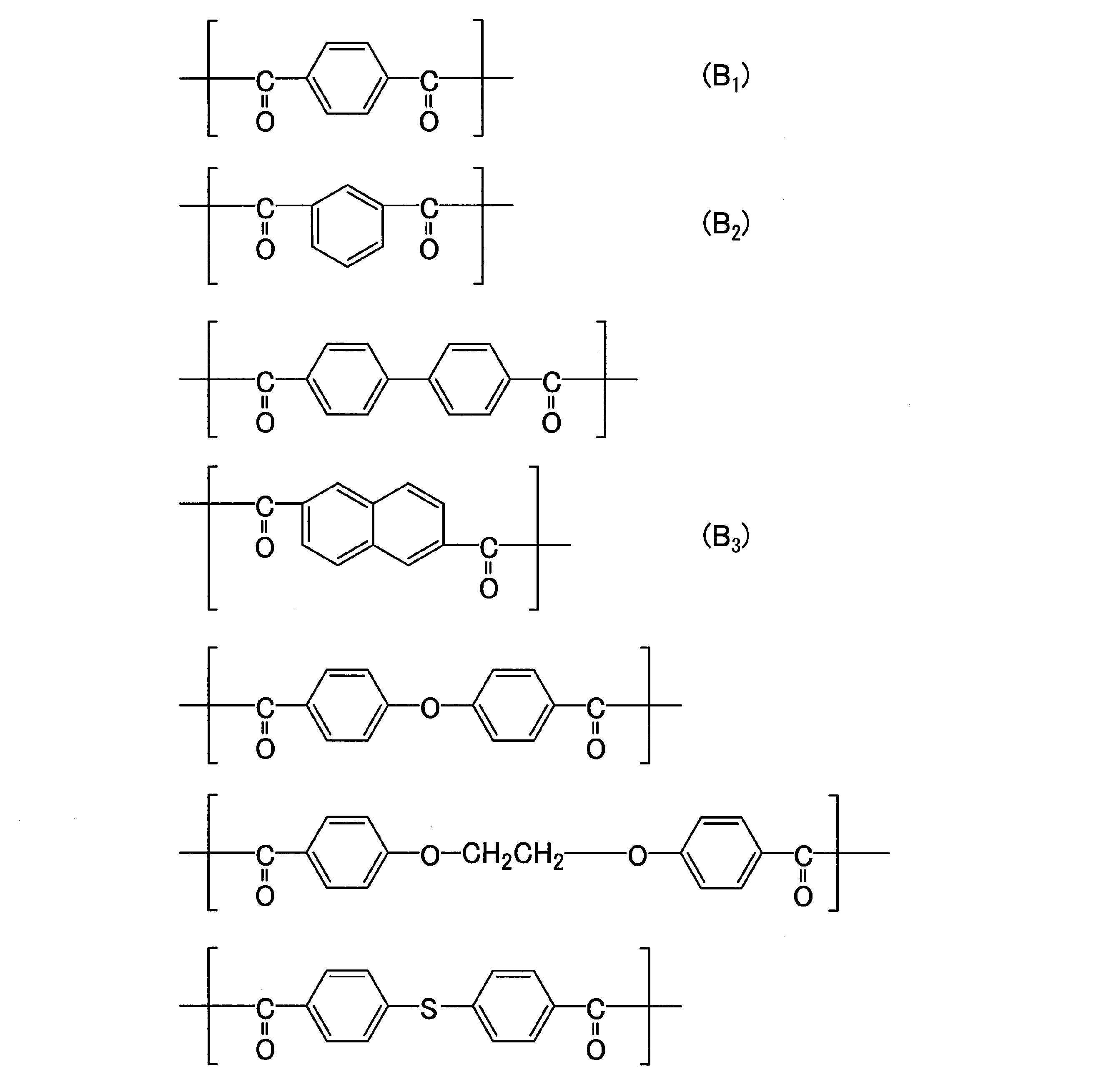
- repeating unit derived from such an aromatic dicarboxylic acid examples include those shown below.
- part of the hydrogen atoms in the aromatic ring is substituted with at least one substituent selected from the group consisting of a halogen atom, an alkyl group and an aryl group. May be.
- aromatic diol examples include 4,4′-dihydroxybiphenyl (aromatic diol that induces (C 1 ) described later), hydroquinone (aromatic diol that induces (C 2 ) described later), and resorcin (described later).
- aromatic diol (C 3 ) -derived aromatic diol), 4,4′-dihydroxydiphenyl ketone, 4,4′-dihydroxydiphenyl ether, bis (4-hydroxyphenyl) methane, 1,2-bis (4-hydroxyphenyl) ethane 4,4′-dihydroxydiphenylsulfone, 4,4′-dihydroxydiphenylthioether, 2,6-dihydroxynaphthalene, 1,5-dihydroxynaphthalene, and some of the hydrogen atoms in the aromatic ring of these aromatic diols , At least one selected from the group consisting of an alkyl group, an aryl group, and a halogen atom Aromatic diol formed by substituted with a substituent can be mentioned.
- the said aromatic diol may be used individually by 1 type in manufacture of liquid crystalline polyester, and may be used in combination of 2 or more type.
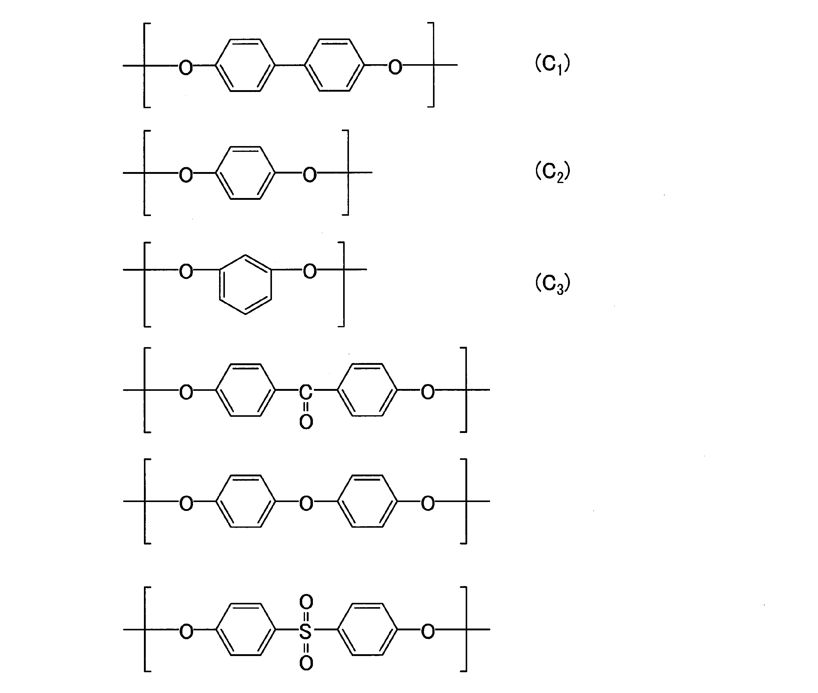
- repeating unit derived from such an aromatic diol examples include those shown below.
- a part of hydrogen atoms in the aromatic ring may be substituted with at least one substituent selected from the group consisting of a halogen atom, an alkyl group and an aryl group. Good.
- halogen atom that is a substituent that the repeating unit (a repeating unit derived from an aromatic hydroxycarboxylic acid, a repeating unit derived from an aromatic dicarboxylic acid, or a repeating unit derived from an aromatic diol) may optionally have Includes a fluorine atom, a chlorine atom, and a bromine atom.
- alkyl group as the substituent include lower alkyl groups having about 1 to 4 carbon atoms such as a methyl group, an ethyl group, and a butyl group.
- the aryl group as the substituent include a phenyl group.
- a particularly suitable liquid crystal polyester will be described.
- a repeating unit derived from an aromatic hydroxycarboxylic acid a repeating unit derived from parahydroxybenzoic acid (A 1 ), 2-hydroxy-6-naphthoic acid or parahydroxybenzoic acid and 2-hydroxy It is preferable to have a repeating unit (A 2 ) derived from both of -6-naphthoic acid; the repeating unit derived from an aromatic dicarboxylic acid includes a repeating unit (B 1 ) derived from terephthalic acid, isophthalic acid It is preferable to have one selected from the group consisting of repeating units derived from acids (B 2 ) and repeating units derived from 2,6-naphthalenedicarboxylic acid (B 3 ); repeating derived from aromatic diols
- the unit is a repeating unit derived from hydroquinone (C 2 ) or 4,4′-dihydroxybiphene. It preferably has a repeating unit (C 2 )
- Particularly preferred liquid crystalline polyester is a repeating unit derived from an aromatic hydroxycarboxylic acid (that is, a repeating unit derived from parahydroxybenzoic acid (A 1 ) or 2-hydroxy-, based on the total number of moles of all repeating units.
- aromatic hydroxycarboxylic acid that is, a repeating unit derived from parahydroxybenzoic acid (A 1 ) or 2-hydroxy-, based on the total number of moles of all repeating units.
- the total of repeating units derived from both 6-naphthoic acid or parahydroxybenzoic acid and 2-hydroxy-6-naphthoic acid (A 2 ) is 30 to 80 mol%, and the repeating units derived from aromatic diol (ie, 10 to 35 mol% of a total of repeating units derived from hydroquinone (C 2 ), or 4,4′-dihydroxybiphenyl or repeating units derived from both hydroquinone and 4,4′-dihydroxybiphenyl (C 1 ),
- Repeating units derived from aromatic dicarboxylic acids ie, repeating units derived from terephthalic acid
- the total of the position (B 1 ), the repeating unit derived from isophthalic acid (B 2 ) and the repeating unit derived from 2,6-naphthalenedicarboxylic acid (B 3 ) is 10 to 35 mol %, Can be mentioned liquid crystal polyester. The total of all repeating units does not exceed 100 mol%.
- the liquid crystal polyester for example, a known method such as a method described in JP-A No. 2002-146003 can be applied. That is, the above-mentioned raw material monomers (aromatic hydroxycarboxylic acid, aromatic dicarboxylic acid, aromatic diol, or derivatives for forming these esters) are melt polymerized (polycondensation) to produce a relatively low molecular weight aromatic polyester (hereinafter referred to as “polyester”). Abbreviated as “prepolymer”.), And then solid-phase polymerization is carried out by heating the prepolymer to a powder. By solid-phase polymerization in this way, the polymerization proceeds further and a higher molecular weight liquid crystal polyester can be obtained.
- the raw material monomers aromatic hydroxycarboxylic acid, aromatic dicarboxylic acid, aromatic diol, or derivatives for forming these esters
- prepolymer melt polymerized (polycondensation) to produce a relatively low molecular weight aromatic polyester
- Melt polymerization may be carried out in the presence of a catalyst.
- a catalyst in this case include metals such as magnesium acetate, stannous acetate, tetrabutyl titanate, lead acetate, sodium acetate, potassium acetate, and antimony trioxide.
- metals such as magnesium acetate, stannous acetate, tetrabutyl titanate, lead acetate, sodium acetate, potassium acetate, and antimony trioxide.
- nitrogen-containing heterocyclic compounds such as 4- (dimethylamino) pyridine and 1-methylimidazole, and nitrogen-containing heterocyclic compounds are preferably used.
- the liquid crystal polyester used in the injection molded product of the present embodiment is preferably a liquid crystal polyester having a flow start temperature determined by the following method of 280 ° C. or higher.
- the flow start temperature of liquid crystal polyester can be set to 280 ° C. or higher in a relatively short time. Then, by using the liquid crystal polyester having such a flow start temperature as the thermoplastic resin of the present embodiment, the obtained molded body has a high degree of heat resistance.
- the flow start temperature of the liquid crystalline polyester used in the injection-molded product of the present embodiment is preferably 420 ° C.
- the flow start temperature of the liquid crystalline polyester used in the injection molded product of the present embodiment is preferably 280 ° C. or higher and 420 ° C. or lower, and more preferably 280 ° C. or higher and 390 ° C. or lower.
- the “flow start temperature” means a capillary rheometer with a die having an inner diameter of 1 mm and a length of 10 mm, and a heating rate of 4 ° C./min under a load of 9.8 MPa (100 kg / cm 2 ).
- the flow initiation temperature is an index representing the molecular weight of liquid crystal polyesters well known in the art (Naoyuki Koide, “Liquid Crystalline Polymer Synthesis / Molding / Application—”, pages 95 to 105, CMC, June 1987). (See 5th issue).
- a flow characteristic evaluation apparatus “Flow Tester CFT-500D” manufactured by Shimadzu Corporation can be used.
- the injection molded product according to the present embodiment may contain a filler as long as the effects of the present invention are not impaired.
- strength can be provided to an injection molded product by containing a filler.
- the filler used in the present embodiment may be an inorganic filler or an organic filler. Further, it may be a fibrous filler, a plate-like filler, or a granular filler.
- fibrous fillers examples include glass fibers; carbon fibers such as pan-based carbon fibers and pitch-based carbon fibers; ceramic fibers such as silica fibers, alumina fibers and silica-alumina fibers; and metal fibers such as stainless steel fibers.
- whiskers such as potassium titanate whisker, barium titanate whisker, wollastonite whisker, aluminum borate whisker, silicon nitride whisker, and silicon carbide whisker are also included.
- Examples of the plate-like filler include talc, mica, graphite, wollastonite, barium sulfate and calcium carbonate.
- Mica may be muscovite, phlogopite, fluorine phlogopite, or tetrasilicon mica.
- particulate filler examples include silica, alumina, titanium oxide, boron nitride, silicon carbide and calcium carbonate.
- the content of the filler is preferably 0 to 70% by mass with respect to the total mass of the injection molded product.
- the injection-molded article according to the present embodiment may contain other components that do not fall under any of the thermoplastic resin and filler as long as the effects of the present invention are not impaired. That is, as one aspect, the injection molded product according to the present embodiment contains the thermoplastic resin, the filler, and other components as desired.
- mold release improvers such as fluororesins and metal soaps
- colorants such as dyes and pigments
- antioxidants heat stabilizers
- ultraviolet absorbers antistatic agents
- the additive generally used for an injection molded product is mentioned.
- Examples of the other components include those having an external lubricant effect such as higher fatty acids, higher fatty acid esters, higher fatty acid metal salts, and fluorocarbon surfactants.
- thermosetting resins such as phenol resin, epoxy resin, and polyimide resin.
- the content of the other components is preferably 0 to 50% by mass with respect to the total mass of the injection molded product.
- the injection molded product having the above configuration an increase in the charge amount can be suppressed.
- the injection-molded product is a fixing part for a printer, it is possible to suppress the position of the transferred electrostatic image from being shifted, and to suppress disturbance of the resulting image.
- the injection-molded product is a camera module, it is possible to suppress dust and the like in the air from adhering to the camera module due to static electricity, and to reduce the occurrence of defects due to dust.
- the above-mentioned injection molded product can be manufactured by the following method. That is, the method for producing an injection molded product of the present embodiment includes a step of injecting the resin composition for injection molding containing the thermoplastic resin into a mold after melting.
- the inner surface of the mold has a concavo-convex shape (a shape complementary to the convex or pear texture) corresponding to the convex or pear texture.
- the said resin composition for injection molding can be manufactured using a well-known method.
- the injection molding in the present embodiment is performed by melting an injection molding resin composition using an injection molding machine (for example, “hydraulic horizontal molding machine PS40E5ASE type” manufactured by Nissei Plastic Industry Co., Ltd.). This can be done by heating the article to an appropriate temperature and injecting it into the mold.
- an injection molding machine for example, “hydraulic horizontal molding machine PS40E5ASE type” manufactured by Nissei Plastic Industry Co., Ltd.
- the temperature at which the resin composition for injection molding is heated and melted for injection may be [Tp + 10] ° C. or higher and [Tp + 50] ° C. or lower based on the flow starting temperature Tp ° C. of the resin composition for injection molding used. preferable.
- the temperature of the mold is preferably selected from the range of room temperature (for example, 23 ° C.) to 180 ° C. from the viewpoint of the cooling rate and productivity of the resin composition for injection molding.
- a concave / convex shape having a desired surface roughness is formed at a position corresponding to the concave / convex portion on the inner surface of the mold on the surface of the injection molded product. Can do. Therefore, according to the manufacturing method of the present embodiment, an injection molded product that can suppress an increase in charge amount is obtained.
- the injection molded product of the present invention is It is an injection molded product for housing interior parts in electrical and electronic equipment, Including one or more parts injection molded from a thermoplastic resin;
- the thermoplastic resin includes at least one selected from the group consisting of a liquid crystal polymer, polyethylene terephthalate, and polyethersulfone, and has a thickness of 0.1 mm or more, preferably 0.1 mm or more and 20 mm or less, more preferably Is 0.2 mm or more and 20 mm or less, more preferably 0.5 mm or more and 20 mm or less, and particularly preferably 1 mm or more and 20 mm or less;
- the surface resistance is 10 12 ⁇ or more, preferably 10 13 ⁇ or more and 10 18 ⁇ or less;
- the surface roughness may be 30 ⁇ m or more and 500 ⁇ m or less in the maximum height (Rmax), or 100 ⁇ m or more and 300 ⁇ m or less, or 138.7 ⁇ m or more and 297.0 ⁇ m or less; It
- Still another aspect of the present invention is Use of injection molded products for housing interior parts in electrical and electronic equipment
- the injection molded article includes one or more parts injection molded from a thermoplastic resin, The thickness is 0.1 mm or more, The surface resistance is 10 12 ⁇ or more, The surface roughness is 30 ⁇ m or more and 500 ⁇ m or less at the maximum height (Rmax). Said use.
- thermoplastic resin includes at least one selected from the group consisting of a liquid crystal polymer, polyethylene terephthalate, and polyethersulfone;
- the thickness is 0.1 mm or more, preferably 0.1 mm or more and 20 mm or less, more preferably 0.2 mm or more and 20 mm or less, further preferably 0.5 mm or more and 20 mm or less, and particularly preferably 1 mm or more and 20 mm or less;
- the surface resistance is 10 12 ⁇ or more, preferably 10 13 ⁇ or more and 10 18 ⁇ or less;
- the surface roughness may be 30 ⁇ m or more and 500 ⁇ m or less in the maximum height (Rmax), or 100 ⁇ m or more and 300 ⁇ m or less, or 138.7 ⁇ m or more and 297.0 ⁇ m or less; It has a concavo-conve
- the surface roughness (Rmax) of the injection-molded product was measured using a non-contact surface roughness meter “Peltometer C5D” manufactured by Feinprof Perhen GmbH.
- the arbitrary location of the surface by which the embossing of the injection molded product was carried out was measured, and in the comparative example, the arbitrary location of the flat surface of the injection molded product was measured.
- the surface resistance of the injection-molded product was measured at 23 ° C. under resistance measurement conditions (using a digital super insulation / microammeter “DSM-8104” manufactured by Toa DKK Corporation) in accordance with “ASTM D257”.
- Examples 1 to 6 Comparative Examples 1 to 3> The following resin was melted and then injected into a mold to form a flat plate having a length of 64 mm, a width of 64 mm, and a thickness of 1 mm. At this time, in Examples 1, 3, and 5, a mold having an uneven shape corresponding to the convex texture on the inner surface was used. In Examples 2, 4 and 6, a mold having an uneven shape corresponding to a textured texture on the inner surface was used. In Comparative Examples 1, 2, and 3, a mold whose inner surface is a mirror surface was used. Table 1 summarizes the types of thermoplastic resin, surface shape, surface roughness (Rmax), and surface resistance of the obtained injection molded product.
- Rmax surface roughness
- Liquid crystal polyester may be abbreviated as LCP
- Sumika Super E6808LHF B Z manufactured by Sumitomo Chemical Co., Ltd.
- Polyethersulfone may be abbreviated as PES
- Sumika Excel 3601GL30 manufactured by Sumitomo Chemical Co., Ltd.
- Polyethylene terephthalate may be abbreviated as PET: DuPont, Rynite FR530BK507
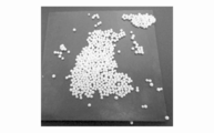
- FIG. 1 is a diagram showing how microbeads adhere to an injection molded product in the evaluation in the examples. Table 1 shows the number of microbeads attached to the injection molded product.
- the injection molded products of Examples 1 to 6 having a surface roughness (Rmax) in the range of 30 ⁇ m or more and 500 ⁇ m or less have a surface roughness (Rmax) outside the range of 30 ⁇ m or more and 500 ⁇ m or less. It was shown that an increase in charge amount can be suppressed as compared with certain injection molded products of Comparative Examples 1 to 3.
- the injection molded articles of Examples 1 to 6 had fewer microbeads attached than the injection molded articles of Comparative Examples 1 to 3.
- the surface specific resistance value surface resistance value
- the injection molded products of Examples 1 to 6 can suppress the increase in the charge amount while maintaining the surface specific resistance value of 10 15 ⁇ or more.
Landscapes
- Engineering & Computer Science (AREA)
- Mechanical Engineering (AREA)
- Manufacturing & Machinery (AREA)
- Injection Moulding Of Plastics Or The Like (AREA)
- Moulds For Moulding Plastics Or The Like (AREA)
Abstract
電気・電子機器における筐体内装部品用の射出成形品であって、熱可塑性樹脂から射出成形された1又は2以上の部品を含み、厚さが、0.1mm以上であり、表面抵抗が、1012Ω以上であり、表面粗さが、最大高さ(Rmax)で30μm以上500μm以下である、射出成形品。
Description
本発明は、射出成形品および射出成形品の製造方法に関するものである。
本願は、2016年8月19日に、日本に出願された特願2016-161200号に基づき優先権を主張し、その内容をここに援用する。
本願は、2016年8月19日に、日本に出願された特願2016-161200号に基づき優先権を主張し、その内容をここに援用する。
レーザープリンターや複写機などの電子写真方式を応用した画像形成装置が広く知られている。一般に、電子写真方式は、帯電、露光、現像、転写、定着の5工程を備えている。具体的には、まず、コロナ放電により感光体表面に均一な電荷を与える(帯電工程)。
次に、光照射により静電画像を形成する(露光工程)。得られた静電画像を、トナーを用いて顕色させる(現像工程)。顕色させた静電画像を、コピー紙に転写する(転写工程)。転写した静電画像を、加熱・圧力または溶媒蒸気などにより定着させる(定着工程)。
次に、光照射により静電画像を形成する(露光工程)。得られた静電画像を、トナーを用いて顕色させる(現像工程)。顕色させた静電画像を、コピー紙に転写する(転写工程)。転写した静電画像を、加熱・圧力または溶媒蒸気などにより定着させる(定着工程)。
ところで、画像形成装置をはじめ、電気・電子機器における筐体内装部品は、熱可塑性樹脂を用いて射出成形により製造できることが知られている(例えば、特許文献1)。通常、画像形成装置における筐体内装部品の表面は、コピー紙の搬送が滞りなく行えるよう平坦になっている。
しかしながら、このような筐体内装部品と搬送コピー紙とが擦れる際には静電気が発生することがある。転写工程から定着工程までの間、トナーは静電気によりコピー紙に付着しているので、筐体内装部品の帯電量が増加すると、転写した静電画像の位置がずれることがある。そして、後の定着工程では、ずれた状態のまま静電画像が定着されるので、結果的に得られる画像が乱れることがある。
また、近年では、画像形成の高速化に伴って、コピー紙の搬送速度が増大しつつある。
コピー紙の搬送速度が増大すると、筐体内装部品の帯電量がさらに増加するので、画像の乱れも大きくなる傾向がある。
また、近年では、画像形成の高速化に伴って、コピー紙の搬送速度が増大しつつある。
コピー紙の搬送速度が増大すると、筐体内装部品の帯電量がさらに増加するので、画像の乱れも大きくなる傾向がある。
さらに、帯電量の増加による不具合は他の電気・電子機器における筐体内装部品においても同様に確認されることがある。
そこで、帯電量の増加を抑制することができる射出成形品およびこのような射出成形品が得られる製造方法が求められている。
本発明はこのような事情に鑑みてなされたものであって、帯電量の増加を抑制できる射出成形品および射出成形品の製造方法を提供することを目的とする。
本発明者らは、上述の課題を解決すべく鋭意検討を重ねた結果、射出成形品の表面粗さを最大高さ(Rmax)で30μm以上500μm以下とすることで、帯電量の増加を抑制できることを見出し、本発明を完成するに至った。
本発明の一態様は、電気・電子機器における筐体内装部品用の射出成形品であって、熱可塑性樹脂を形成材料として含み、厚さは、0.1mm以上であり、表面抵抗は、1012Ω以上であり、表面粗さは、最大高さ(Rmax)で30μm以上500μm以下である射出成形品を提供する。
なお、本明細書において「筐体内装部品」とは、筐体の内部に備えられた部品を意味する。
なお、本明細書において「筐体内装部品」とは、筐体の内部に備えられた部品を意味する。
本発明の一態様である射出成形品は、筐体内装部品が、コネクター、カメラモジュール、送風ファンまたはプリンター向けの定着部品であることが好ましい。
本発明の一態様である射出成形品は、表面粗さが、最大高さ(Rmax)で30μm以上500μm以下である凸シボまたは梨地シボの凹凸形状を有することが好ましい。
本発明の一態様は、上記の射出成形品の製造方法であって、熱可塑性樹脂を含む射出成形用樹脂組成物を溶融させた後、金型内に射出する工程を有し、前記金型の内表面は、凸シボまたは梨地シボに対応する凹凸形状を有する射出成形品の製造方法を提供する。
即ち、本発明は以下に関する。
[1] 電気・電子機器における筐体内装部品用の射出成形品であって、
熱可塑性樹脂から射出成形された1又は2以上の部品をを含み、
厚さが、0.1mm以上であり、
表面抵抗が、1012Ω以上であり、
表面粗さが、最大高さ(Rmax)で30μm以上500μm以下である、
射出成形品。
[2]前記筐体内装部品は、コネクター、カメラモジュール、送風ファンまたはプリンター向けの定着部品である[1]に記載の射出成形品。
[3] 表面粗さが、最大高さ(Rmax)で30μm以上500μm以下である凸シボまたは梨地シボの凹凸形状を有する[1]または[2]に記載の射出成形品。
[4][1]~[3]のいずれか1つに記載の射出成形品の製造方法であって、
前記熱可塑性樹脂を含む射出成形用樹脂組成物を溶融させた後、金型内に射出する工程を含み、
前記金型の内表面は、凸シボまたは梨地シボに対応する凹凸形状を有する、射出成形品の製造方法。
[1] 電気・電子機器における筐体内装部品用の射出成形品であって、
熱可塑性樹脂から射出成形された1又は2以上の部品をを含み、
厚さが、0.1mm以上であり、
表面抵抗が、1012Ω以上であり、
表面粗さが、最大高さ(Rmax)で30μm以上500μm以下である、
射出成形品。
[2]前記筐体内装部品は、コネクター、カメラモジュール、送風ファンまたはプリンター向けの定着部品である[1]に記載の射出成形品。
[3] 表面粗さが、最大高さ(Rmax)で30μm以上500μm以下である凸シボまたは梨地シボの凹凸形状を有する[1]または[2]に記載の射出成形品。
[4][1]~[3]のいずれか1つに記載の射出成形品の製造方法であって、
前記熱可塑性樹脂を含む射出成形用樹脂組成物を溶融させた後、金型内に射出する工程を含み、
前記金型の内表面は、凸シボまたは梨地シボに対応する凹凸形状を有する、射出成形品の製造方法。
本発明の一態様によれば、帯電量の増加を抑制できる射出成形品および射出成形品の製造方法が提供される。
<射出成形品>
本実施形態の射出成形品は、電気・電子機器における筐体内装部品用の射出成形品である。電気・電子機器としては、カメラ、パソコン、携帯電話、スマートフォン、タブレット、プリンター、プロジェクターなどが挙げられる。このような電気・電子機器における筐体内装部品としては、コネクター、カメラモジュール、送風ファンまたはプリンター向けの定着部品が挙げられる。別の側面として、前記筐体内装部品は、射出成型品と他の部材が擦れる箇所を有するパーツで構成される。
本実施形態の射出成形品は、電気・電子機器における筐体内装部品用の射出成形品である。電気・電子機器としては、カメラ、パソコン、携帯電話、スマートフォン、タブレット、プリンター、プロジェクターなどが挙げられる。このような電気・電子機器における筐体内装部品としては、コネクター、カメラモジュール、送風ファンまたはプリンター向けの定着部品が挙げられる。別の側面として、前記筐体内装部品は、射出成型品と他の部材が擦れる箇所を有するパーツで構成される。
本実施形態の射出成形品の厚さは、0.1mm以上であり、好ましくは0.2mm以上であり、より好ましくは0.5mm以上であり、さらに好ましくは1mm以上である。また、射出成形品の厚さは、好ましくは20mm以下である。
1つの側面として、本実施形態の射出成形品の厚さは、0.1mm以上20mm以下が好ましく、0.2mm以上20mm以下がより好ましく、0.5mm以上20mm以下がさらに好ましく、1mm以上20mm以下が特に好ましい。
本明細書において、「射出成形品の厚さ」とは、射出成形品が有する凹凸(例えばシボ)の頂点からその対向面までの厚さ(すなわち、射出成形品が有する凹凸の頂点からその対向面までの最短距離)を意味する。射出成形品が送風ファンであるときなど、その厚さが不均一である場合は、設計上の、最も薄い部分の厚さ(すなわち射出成形品が有する凹凸の頂点からその対向面までの厚さの最小値)が0.1mm以上であればよく、好ましくは0.2mm以上であり、より好ましくは0.5mm以上であり、さらに好ましくは1mm以上である。また、設計上の、最も厚い部分の厚さ(すなわち射出成形品が有する凹凸の頂点からその対向面までの厚さの最大値)は20mm以下であると好ましい。
射出成形品の実製品の厚さは、マイクロメーターまたは非接触3次元測定器(株式会社ミツトヨ製の「QuickVisionPRO」)を用いて、射出成形品の実製品の厚さをランダムに3箇所測定したときの、測定値を平均することで得られる。なお、マイクロメーターおよび上記非接触2次元測定器のいずれを選択した場合でも成形品の厚さは定量的に得ることができる。
1つの側面として、本実施形態の射出成形品の厚さは、0.1mm以上20mm以下が好ましく、0.2mm以上20mm以下がより好ましく、0.5mm以上20mm以下がさらに好ましく、1mm以上20mm以下が特に好ましい。
本明細書において、「射出成形品の厚さ」とは、射出成形品が有する凹凸(例えばシボ)の頂点からその対向面までの厚さ(すなわち、射出成形品が有する凹凸の頂点からその対向面までの最短距離)を意味する。射出成形品が送風ファンであるときなど、その厚さが不均一である場合は、設計上の、最も薄い部分の厚さ(すなわち射出成形品が有する凹凸の頂点からその対向面までの厚さの最小値)が0.1mm以上であればよく、好ましくは0.2mm以上であり、より好ましくは0.5mm以上であり、さらに好ましくは1mm以上である。また、設計上の、最も厚い部分の厚さ(すなわち射出成形品が有する凹凸の頂点からその対向面までの厚さの最大値)は20mm以下であると好ましい。
射出成形品の実製品の厚さは、マイクロメーターまたは非接触3次元測定器(株式会社ミツトヨ製の「QuickVisionPRO」)を用いて、射出成形品の実製品の厚さをランダムに3箇所測定したときの、測定値を平均することで得られる。なお、マイクロメーターおよび上記非接触2次元測定器のいずれを選択した場合でも成形品の厚さは定量的に得ることができる。
以下では、電気・電子機器の筐体内装部品として、プリンター向けの定着部品である場合を例に挙げて説明するが、本実施形態はこれに限定されない。
通常、プリンター向けの定着部品の表面は、コピー紙の搬送が滞りなく行えるよう平坦になっている。しかしながら、上記定着部品と搬送コピー紙とが擦れる際には静電気が発生することがある。画像形成における転写工程から定着工程までの間、トナーは静電気によりコピー紙に付着しているので、上記定着部品の帯電量が増加すると、転写した静電画像の位置がずれることがある。そして、後の定着工程では、ずれた状態のまま静電画像が定着されるので、結果的に得られる画像が乱れることがある。
本発明者らは、上述の課題を解決すべく鋭意検討を重ねた結果、射出成形品、例えばプリンター向けの定着部品、の表面粗さを最大高さ(Rmax)で30μm以上500μm以下とすることで、帯電量の増加を抑制できることを見出した。これは、表面粗さが上記範囲内であることで、コピー紙と上記定着部品との接触面積が少なくなるため、静電気の発生を低減できるからである。
別の側面として、表面粗さは、最大高さ(Rmax)で100μm以上300μm以下であってもよく、138.7μm以上297.0μm以下であってもよい。
別の側面として、表面粗さは、最大高さ(Rmax)で100μm以上300μm以下であってもよく、138.7μm以上297.0μm以下であってもよい。
また、本実施形態の射出成形品、例えばプリンター向けの定着部品は、表面粗さが、最大高さ(Rmax)で30μm以上500μm以下である凸シボまたは梨地シボの凹凸形状を有することが好ましい。
本明細書において、「凸シボ」とは規則的なパターンにより形成されたシワ模様のことである。また、「梨地シボ」とは、不規則なパターンにより形成されたシワ模様のことである。
本明細書において、「凸シボ」とは規則的なパターンにより形成されたシワ模様のことである。また、「梨地シボ」とは、不規則なパターンにより形成されたシワ模様のことである。
本実施形態の射出成形品、例えばプリンター向けの定着部品における表面粗さは、適宜選択することができる。例えば、射出成形品の表面粗さ(例えばプリンター向けの定着部品)は、射出成形品(例えば、プリンター向けの定着部品)の厚さの1/2以下であってもよい。
本明細書において、射出成形品の表面粗さは、「JIS B 0601:1982」に準拠して、例えば、Feinpruf Perthen GmbH社製の非接触表面粗さ計「ペルトメーターC5D」を用いて測定した値を採用できる。なお、本明細書における射出成形品、例えばプリンター向けの定着部品の表面粗さは、射出成形品(例えば、プリンター向けの定着部品)におけるシボ加工がされた表面の任意の箇所を、12mmの測定幅で1回測定した値である。
本実施形態の射出成形品、例えば、プリンター向けの定着部品において、トナーが付着したコピー紙が接触する側の面の表面抵抗は、1012Ω以上1018Ω以下であり、好ましくは1013Ω以上1018Ω以下である。表面抵抗が1012Ω未満である場合、コピー紙に付着したトナーが剥がれるなどの不具合が生じることがある。
なお、射出成形品(例えば、プリンター向けの定着部品)の表面抵抗は、「ASTM D257」に準拠した公知の測定装置を用いて、成形品が擦れる面を測定した値を採用することができる。
射出成形品(例えば、プリンター向けの定着部品)の表面抵抗は、例えば「ASTM D257」に準拠した抵抗測定条件(東亜ディーケーケー株式会社製のデジタル超絶縁/微少電流計「DSM-8104」を使用、測定温度23℃)により測定することができる。
射出成形品(例えば、プリンター向けの定着部品)の表面抵抗は、例えば「ASTM D257」に準拠した抵抗測定条件(東亜ディーケーケー株式会社製のデジタル超絶縁/微少電流計「DSM-8104」を使用、測定温度23℃)により測定することができる。
本実施形態の射出成形品は、熱可塑性樹脂を形成材料として含む。以下、本実施形態に係る熱可塑性樹脂について詳細に説明する。
[熱可塑性樹脂]
本実施形態に係る熱可塑性樹脂としては、射出成形が可能な限り特に限定されない。熱可塑性樹脂としては、ポリアミド、ポリアセタール、ポリエチレンテレフタレート、ポリブチレンテレフタレート、ポリフェニレンスルフィド、ポリエーテルエーテルケトン、液晶ポリマー、ポリテトラフルオロエチレンなどの結晶性樹脂;ポリカーボネート、ポリフェニレンエーテル、ポリアリレート、ポリスルホン、ポリエーテルスルホン、ポリエーテルイミド、ポリアミドイミドなどの非晶性樹脂が挙げられる。
なかでも、液晶ポリマー、ポリエチレンテレフタレート、ポリエーテルスルホン等が好ましい。
上記のなかでも、液晶ポリマーは耐熱性や溶融時の流動性に優れるため、好ましく用いられるが、帯電量がより高くなる傾向がある。そのため、液晶ポリマーを本実施形態に用いた場合、とりわけ本発明の効果がより顕著にあらわれる傾向がある。
本実施形態に係る熱可塑性樹脂としては、射出成形が可能な限り特に限定されない。熱可塑性樹脂としては、ポリアミド、ポリアセタール、ポリエチレンテレフタレート、ポリブチレンテレフタレート、ポリフェニレンスルフィド、ポリエーテルエーテルケトン、液晶ポリマー、ポリテトラフルオロエチレンなどの結晶性樹脂;ポリカーボネート、ポリフェニレンエーテル、ポリアリレート、ポリスルホン、ポリエーテルスルホン、ポリエーテルイミド、ポリアミドイミドなどの非晶性樹脂が挙げられる。
なかでも、液晶ポリマー、ポリエチレンテレフタレート、ポリエーテルスルホン等が好ましい。
上記のなかでも、液晶ポリマーは耐熱性や溶融時の流動性に優れるため、好ましく用いられるが、帯電量がより高くなる傾向がある。そのため、液晶ポリマーを本実施形態に用いた場合、とりわけ本発明の効果がより顕著にあらわれる傾向がある。
熱可塑性樹脂は、1種を単独で用いてもよいし、2種以上を併用してもよい。
(液晶ポリマー)
本実施形態に係る熱可塑性樹脂の一例として、液晶ポリマーを用いる場合を説明するが、本実施形態はこれに限定されない。
本実施形態に係る熱可塑性樹脂の一例として、液晶ポリマーを用いる場合を説明するが、本実施形態はこれに限定されない。
本実施形態で用いられる液晶ポリマーは、サーモトロピック液晶ポリマーであり、光学的異方性を示す溶融体を450℃以下の温度で形成し得るものである。以下では、サーモトロピック液晶ポリマーとして、液晶ポリエステルを例に挙げて説明する。液晶ポリエステルとしては、具体的には、
(1)芳香族ヒドロキシカルボン酸と芳香族ジカルボン酸と芳香族ジオールとを重合して得られるもの、
(2)複数種の芳香族ヒドロキシカルボン酸を重合して得られるもの、
(3)芳香族ジカルボン酸と芳香族ジオールとを重合して得られるもの、
(4)ポリエチレンテレフタレートなどの結晶性ポリエステルに芳香族ヒドロキシカルボン酸を反応させて得られるもの、
などを挙げることができる。
(1)芳香族ヒドロキシカルボン酸と芳香族ジカルボン酸と芳香族ジオールとを重合して得られるもの、
(2)複数種の芳香族ヒドロキシカルボン酸を重合して得られるもの、
(3)芳香族ジカルボン酸と芳香族ジオールとを重合して得られるもの、
(4)ポリエチレンテレフタレートなどの結晶性ポリエステルに芳香族ヒドロキシカルボン酸を反応させて得られるもの、
などを挙げることができる。
なお、液晶ポリエステルの製造において、原料モノマーとして使用する芳香族ヒドロキシカルボン酸、芳香族ジカルボン酸および芳香族ジオールの一部または全部を、予めエステル形成性誘導体にして重合に供することもできる。このようなエステル形成性誘導体を用いることにより、液晶ポリエステルをより容易に製造できるという利点がある。
エステル形成性誘導体としては次のようなものが例示される。
分子内にカルボキシル基を有する芳香族ヒドロキシカルボン酸および芳香族ジカルボン酸のエステル形成性誘導体の例としては、前記カルボキシル基が、ハロホルミル基(酸ハロゲン化物)やアシルオキシカルボニル基(酸無水物)などの高反応性の基に転化したものや、前記カルボキシル基が、エステル交換反応によりポリエステルを生成するように、一価のアルコール類やエチレングリコールなどの多価アルコール類、フェノール類などとエステルを形成したものが挙げられる。
芳香族ヒドロキシカルボン酸および芳香族ジオールのようなフェノール性水酸基を有する化合物の重合可能な誘導体の例としては、前記フェノール性水酸基が、エステル交換反応によりポリエステルを生成するように、低級カルボン酸類とエステルを形成したものが挙げられる。
分子内にカルボキシル基を有する芳香族ヒドロキシカルボン酸および芳香族ジカルボン酸のエステル形成性誘導体の例としては、前記カルボキシル基が、ハロホルミル基(酸ハロゲン化物)やアシルオキシカルボニル基(酸無水物)などの高反応性の基に転化したものや、前記カルボキシル基が、エステル交換反応によりポリエステルを生成するように、一価のアルコール類やエチレングリコールなどの多価アルコール類、フェノール類などとエステルを形成したものが挙げられる。
芳香族ヒドロキシカルボン酸および芳香族ジオールのようなフェノール性水酸基を有する化合物の重合可能な誘導体の例としては、前記フェノール性水酸基が、エステル交換反応によりポリエステルを生成するように、低級カルボン酸類とエステルを形成したものが挙げられる。
さらに、エステル形成性を阻害しない程度であれば、上述の芳香族ヒドロキシカルボン酸、芳香族ジカルボン酸または芳香族ジオールは、その芳香環に、塩素原子、フッ素原子などのハロゲン原子;メチル基、エチル基、ブチル基などの炭素数1~10のアルキル基;フェニル基などの炭素数6~20のアリール基を置換基として有していてもよい。
芳香族ヒドロキシカルボン酸としては、例えば、p-ヒドロキシ安息香酸(後述の(A1)を誘導する芳香族ヒドロキシカルボン酸)、m-ヒドロキシ安息香酸、6-ヒドロキシ-2-ナフトエ酸(後述の(A2)を誘導する芳香族ヒドロキシカルボン酸)、3-ヒドロキシ-2-ナフトエ酸、5-ヒドロキシ-1-ナフトエ酸、4-ヒドロキシ-4’-カルボキシジフェニルエーテルや、これらの芳香族ヒドロキシカルボン酸の芳香環にある水素原子の一部が、アルキル基、アリール基およびハロゲン原子からなる群より選ばれる少なくとも1種の置換基で置換されてなる芳香族ヒドロキシカルボン酸が挙げられる。前記芳香族ヒドロキシカルボン酸は、液晶ポリエステルの製造において、1種を単独で用いてもよく、2種以上を組み合わせて用いてもよい。
このような芳香族ヒドロキシカルボン酸に由来する繰返し単位としては、例えば、以下に示すものが挙げられる。なお、芳香族ヒドロキシカルボン酸に由来する繰返し単位は、その芳香環にある水素原子の一部が、ハロゲン原子、アルキル基およびアリール基からなる群より選ばれる少なくとも1種の置換基で置換されていてもよい。
ここで、「由来する」とは重合するために、原料モノマーから化学構造が変化することを意味する。
ここで、「由来する」とは重合するために、原料モノマーから化学構造が変化することを意味する。

芳香族ジカルボン酸としては、例えば、テレフタル酸(後述の(B1)を誘導する芳香族ジカルボン酸)、イソフタル酸(後述の(B2)を誘導する芳香族ジカルボン酸)、ビフェニル-4,4’-ジカルボン酸、2,6-ナフタレンジルボン酸(後述の(B3)を誘導する芳香族ジカルボン酸)、ジフェニルエーテル-4,4’-ジカルボン酸、ジフェニルチオエーテル-4,4’-ジカルボン酸や、これらの芳香族ジカルボン酸の芳香環にある水素原子の一部が、アルキル基、アリール基およびハロゲン原子からなる群より選ばれる少なくとも1種の置換基で置換されてなる芳香族ジカルボン酸が挙げられる。前記芳香族ジカルボン酸は、液晶ポリエステルの製造において、1種を単独で用いてもよく、2種以上を組み合わせて用いてもよい。
このような芳香族ジカルボン酸に由来する繰返し単位としては、例えば、以下に示すものが挙げられる。なお、以下に示す芳香族ジカルボン酸に由来する繰返し単位は、その芳香環にある水素原子の一部が、ハロゲン原子、アルキル基およびアリール基からなる群より選ばれる少なくとも1種の置換基で置換されていてもよい。
芳香族ジオールとしては、例えば、4,4’-ジヒドロキシビフェニル(後述の(C1)を誘導する芳香族ジオール)、ハイドロキノン(後述の(C2)を誘導する芳香族ジオール)、レゾルシン(後述の(C3)を誘導する芳香族ジオール)、4,4’-ジヒドロキシジフェニルケトン、4,4’-ジヒドロキシジフェニルエーテル、ビス(4-ヒドロキシフェニル)メタン、1,2-ビス(4-ヒドロキシフェニル)エタン、4,4’-ジヒドロキシジフェニルスルホン、4,4’-ジヒドロキシジフェニルチオエーテル、2,6-ジヒドロキシナフタレン、1,5-ジヒドロキシナフタレンや、これらの芳香族ジオールの芳香環にある水素原子の一部が、アルキル基、アリール基およびハロゲン原子からなる群より選ばれる少なくとも1種の置換基で置換されてなる芳香族ジオールが挙げられる。前記芳香族ジオールは、液晶ポリエステルの製造において、1種を単独で用いてもよく、2種以上を組み合わせて用いてもよい。
このような芳香族ジオールに由来する繰返し単位としては、例えば、以下に示すものが挙げられる。なお、芳香族ジオールに由来する繰返し単位は、その芳香環にある水素原子の一部が、ハロゲン原子、アルキル基およびアリール基からなる群より選ばれる少なくとも1種の置換基で置換されていてもよい。
前記繰返し単位(芳香族ヒドロキシカルボン酸に由来する繰返し単位、芳香族ジカルボン酸に由来する繰返し単位、芳香族ジオールに由来する繰返し単位)が任意に有していてもよい置換基であるハロゲン原子としては、フッ素原子、塩素原子、臭素原子が挙げられる。前記置換基であるアルキル基としては、メチル基、エチル基、ブチル基などの炭素数1~4程度の低級アルキル基が挙げられる。前記置換基であるアリール基としては、フェニル基が挙げられる。
特に好適な液晶ポリエステルに関し説明する。
前記液晶ポリエステルは、芳香族ヒドロキシカルボン酸に由来する繰返し単位としては、パラヒドロキシ安息香酸に由来する繰返し単位(A1)、または2-ヒドロキシ-6-ナフトエ酸もしくはパラヒドロキシ安息香酸と2-ヒドロキシ-6-ナフトエ酸の両方に由来する繰返し単位(A2)を有していることが好ましく;芳香族ジカルボン酸に由来する繰返し単位としては、テレフタル酸に由来する繰返し単位(B1)、イソフタル酸に由来する繰返し単位(B2)および2,6-ナフタレンジカルボン酸(B3)に由来する繰返し単位からなる群より選ばれるものを有していることが好ましく;芳香族ジオールに由来する繰返し単位としては、ヒドロキノンに由来する繰返し単位(C2)、または4,4’-ジヒドロキシビフェニルもしくはヒドロキノンと4,4’-ジヒドロキシビフェニルの両方に由来する繰返し単位(C1)を有していることが好ましい。
前記液晶ポリエステルは、芳香族ヒドロキシカルボン酸に由来する繰返し単位としては、パラヒドロキシ安息香酸に由来する繰返し単位(A1)、または2-ヒドロキシ-6-ナフトエ酸もしくはパラヒドロキシ安息香酸と2-ヒドロキシ-6-ナフトエ酸の両方に由来する繰返し単位(A2)を有していることが好ましく;芳香族ジカルボン酸に由来する繰返し単位としては、テレフタル酸に由来する繰返し単位(B1)、イソフタル酸に由来する繰返し単位(B2)および2,6-ナフタレンジカルボン酸(B3)に由来する繰返し単位からなる群より選ばれるものを有していることが好ましく;芳香族ジオールに由来する繰返し単位としては、ヒドロキノンに由来する繰返し単位(C2)、または4,4’-ジヒドロキシビフェニルもしくはヒドロキノンと4,4’-ジヒドロキシビフェニルの両方に由来する繰返し単位(C1)を有していることが好ましい。
そして、これらの組み合わせとしては、下記(a)~(h)で表されるものが好ましい。これら(a)~(h)の繰返し単位の組み合わせであれば、良好な電気絶縁性を有する液晶ポリエステルが得られる。
(a):(A1)、(B1)および(C1)からなる組み合わせ、または、(A1)、(B1)、(B2)および(C1)からなる組み合わせ。
(b):(A2)、(B3)および(C2)からなる組み合わせ、または(A2)、(B1)、(B3)および(C2)からなる組み合わせ。
(c):(A1)および(A2)からなる組み合わせ。
(d):(a)の繰返し単位の組み合わせにおいて、(A1)の一部または全部を(A2)で置きかえたもの。
(e):(a)の繰返し単位の組み合わせにおいて、(B1)の一部または全部を(B3)で置きかえたもの。
(f):(a)の繰返し単位の組み合わせにおいて、(C1)の一部または全部を(C3)で置きかえたもの。
(g):(b)の繰返し単位の組み合わせにおいて、(A2)の一部または全部を(A1)で置きかえたもの。
(h):(c)の繰返し単位の組み合わせに、(B1)と(C2)を加えたもの。
(b):(A2)、(B3)および(C2)からなる組み合わせ、または(A2)、(B1)、(B3)および(C2)からなる組み合わせ。
(c):(A1)および(A2)からなる組み合わせ。
(d):(a)の繰返し単位の組み合わせにおいて、(A1)の一部または全部を(A2)で置きかえたもの。
(e):(a)の繰返し単位の組み合わせにおいて、(B1)の一部または全部を(B3)で置きかえたもの。
(f):(a)の繰返し単位の組み合わせにおいて、(C1)の一部または全部を(C3)で置きかえたもの。
(g):(b)の繰返し単位の組み合わせにおいて、(A2)の一部または全部を(A1)で置きかえたもの。
(h):(c)の繰返し単位の組み合わせに、(B1)と(C2)を加えたもの。
特に好ましい液晶ポリエステルとしては、全繰返し単位の合計モル数に対して、芳香族ヒドロキシカルボン酸に由来する繰返し単位(すなわち、パラヒドロキシ安息香酸に由来する繰返し単位(A1)、または2-ヒドロキシ-6-ナフトエ酸もしくはパラヒドロキシ安息香酸と2-ヒドロキシ-6-ナフトエ酸の両方に由来する繰返し単位(A2))の合計が30~80モル%、芳香族ジオールに由来する繰返し単位(すなわち、ヒドロキノンに由来する繰返し単位(C2)、または4,4’-ジヒドロキシビフェニルもしくはヒドロキノンと4,4’-ジヒドロキシビフェニルの両方に由来する繰返し単位(C1))の合計が10~35モル%、芳香族ジカルボン酸に由来する繰返し単位(すなわち、テレフタル酸に由来する繰返し単位(B1)、イソフタル酸に由来する繰返し単位(B2)および2,6-ナフタレンジカルボン酸に由来する繰返し単位(B3)からなる群より選ばれる繰り返し単位)の合計が10~35モル%、である液晶ポリエステルを挙げることができる。
なお、全繰返し単位の合計は100モル%を超えない。
なお、全繰返し単位の合計は100モル%を超えない。
前記液晶ポリエステルの製造方法としては、例えば、特開2002-146003号公報に記載の方法などの公知の方法が適用できる。すなわち、上述の原料モノマー(芳香族ヒドロキシカルボン酸、芳香族ジカルボン酸、芳香族ジオールまたはこれらのエステル形成用誘導体)を溶融重合(重縮合)させて、比較的低分子量の芳香族ポリエステル(以下、「プレポリマー」と略記する。)を得、次いで、このプレポリマーを粉末とし、加熱することにより固相重合する方法が挙げられる。このように固相重合させることにより、重合がより進行して、より高分子量の液晶ポリエステルを得ることができる。
その他、最も基本的な構造となる前記(a)、(b)の繰返し単位の組み合わせを有する液晶ポリエステルの製造方法については、特公昭47-47870号公報、特公昭63-3888号公報などにも記載されている。
溶融重合は、触媒の存在下で行ってもよく、この場合の触媒の例としては、酢酸マグネシウム、酢酸第一錫、テトラブチルチタネート、酢酸鉛、酢酸ナトリウム、酢酸カリウム、三酸化アンチモンなどの金属化合物や、4-(ジメチルアミノ)ピリジン、1-メチルイミダゾールなどの含窒素複素環式化合物が挙げられ、含窒素複素環式化合物が好ましく用いられる。
本実施形態の射出成形品に使用する液晶ポリエステルとしては、下記の方法で求められる流動開始温度が280℃以上の液晶ポリエステルであることが好ましい。上述のように、液晶ポリエステルの製造において固相重合を用いた場合には、液晶ポリエステルの流動開始温度を280℃以上にすることが比較的短時間で可能である。そして、このような流動開始温度の液晶ポリエステルを本実施形態の熱可塑性樹脂として用いることにより、得られる成形体は高度の耐熱性を有するものとなる。一方、成形体を実用的な温度範囲で成形する面では、本実施形態の射出成形品に使用する液晶ポリエステルの流動開始温度は420℃以下が好ましく、390℃以下であればさらに好ましい。
すなわち、1つの側面として、本実施形態の射出成形品に使用する液晶ポリエステルの流動開始温度は、280℃以上420℃以下が好ましく、280℃以上390℃以下がより好ましい。
すなわち、1つの側面として、本実施形態の射出成形品に使用する液晶ポリエステルの流動開始温度は、280℃以上420℃以下が好ましく、280℃以上390℃以下がより好ましい。
ここで、「流動開始温度」とは、内径1mm、長さ10mmのダイスを取付けた毛細管型レオメーターを用い、9.8MPa(100kg/cm2)の荷重下において昇温速度4℃/分で液晶ポリエステルをノズルから押出すときに、溶融粘度が4800Pa・s(48000ポイズ)を示す温度である。流動開始温度は、当技術分野で周知の液晶ポリエステルの分子量を表す指標である(小出直之編、「液晶性ポリマー合成・成形・応用-」、95~105頁、シーエムシー、1987年6月5日発行を参照)。流動開始温度を測定する装置としては、例えば、(株)島津製作所製の流動特性評価装置「フローテスターCFT-500D」を用いることができる。
[充填材]
本実施形態に係る射出成形品は、本発明の効果を損なわない範囲において、充填材を含有してもよい。本実施形態では、充填材を含有することで、射出成形品に十分な強度を付与することができる。
本実施形態に係る射出成形品は、本発明の効果を損なわない範囲において、充填材を含有してもよい。本実施形態では、充填材を含有することで、射出成形品に十分な強度を付与することができる。
本実施形態で用いられる充填材は、無機充填材であってもよいし、有機充填材であってもよい。また、繊維状充填材であってもよく、板状充填材であってもよく、粒状充填材であってもよい。
繊維状充填材の例としては、ガラス繊維;パン系炭素繊維、ピッチ系炭素繊維などの炭素繊維;シリカ繊維、アルミナ繊維、シリカアルミナ繊維などのセラミック繊維;およびステンレス繊維などの金属繊維が挙げられる。また、チタン酸カリウムウイスカー、チタン酸バリウムウイスカー、ウォラストナイトウイスカー、ホウ酸アルミニウムウイスカー、窒化ケイ素ウイスカー、炭化ケイ素ウイスカーなどのウイスカーも挙げられる。
板状充填材の例としては、タルク、マイカ、グラファイト、ウォラストナイト、硫酸バリウムおよび炭酸カルシウムなどが挙げられる。マイカは、白雲母であってもよいし、金雲母であってもよいし、フッ素金雲母であってもよいし、四ケイ素雲母であってもよい。
粒状充填材の例としては、シリカ、アルミナ、酸化チタン、窒化ホウ素、炭化ケイ素および炭酸カルシウムなどが挙げられる。
充填材の含有量は、射出成型品の総質量に対して、0~70質量%が好ましい。
[その他の成分]
本実施形態に係る射出成形品は、本発明の効果を損なわない範囲において、上記熱可塑性樹脂および充填材のいずれにも該当しない、他の成分を含有してもよい。
すなわち、1つの側面として、本実施形態に係る射出成型品は、上記熱可塑性樹脂と、充填材と、所望により他の成分を含有する。
本実施形態に係る射出成形品は、本発明の効果を損なわない範囲において、上記熱可塑性樹脂および充填材のいずれにも該当しない、他の成分を含有してもよい。
すなわち、1つの側面として、本実施形態に係る射出成型品は、上記熱可塑性樹脂と、充填材と、所望により他の成分を含有する。
上記他の成分の例としては、フッ素樹脂、金属石鹸類などの離型改良剤;染料、顔料などの着色剤;酸化防止剤;熱安定剤;紫外線吸収剤;帯電防止剤;界面活性剤などの、射出成形品に一般的に使用される添加剤が挙げられる。
また、上記他の成分の例としては、高級脂肪酸、高級脂肪酸エステル、高級脂肪酸金属塩、フルオロカーボン系界面活性剤などの外部滑剤効果を有するものも挙げられる。
さらに、上記他の成分の例としては、フェノール樹脂、エポキシ樹脂、ポリイミド樹脂などの熱硬化性樹脂も挙げられる。
上記他の成分の含有量は、射出成型品の総質量に対して0~50質量%が好ましい。
以上のような構成の射出成形品によれば、帯電量の増加を抑制することができる。これにより、例えば射出成形品がプリンター向けの定着部品である場合には、転写した静電画像の位置がずれるのを抑制し、結果的に得られる画像の乱れを抑制することができる。
また、例えば射出成形品がカメラモジュールである場合には、空気中の埃などが静電気によってカメラモジュールに付着するのを抑制し、埃による不具合の発生を低減することができる。
また、例えば射出成形品がカメラモジュールである場合には、空気中の埃などが静電気によってカメラモジュールに付着するのを抑制し、埃による不具合の発生を低減することができる。
<射出成形品の製造方法>
上述した射出成形品は、以下の方法により製造することができる。すなわち、本実施形態の射出成形品の製造方法は、上記熱可塑性樹脂を含む射出成形用樹脂組成物を溶融させた後、金型内に射出する工程を有する。金型の内表面は、凸シボまたは梨地シボに対応する凹凸形状(凸シボまたは梨地シボと相補的な形状)を有する。
なお、前記射出成形用樹脂組成物は、公知の方法を用いて製造することができる。
上述した射出成形品は、以下の方法により製造することができる。すなわち、本実施形態の射出成形品の製造方法は、上記熱可塑性樹脂を含む射出成形用樹脂組成物を溶融させた後、金型内に射出する工程を有する。金型の内表面は、凸シボまたは梨地シボに対応する凹凸形状(凸シボまたは梨地シボと相補的な形状)を有する。
なお、前記射出成形用樹脂組成物は、公知の方法を用いて製造することができる。
本実施形態における射出成形は、射出成形機(例えば、日精樹脂工業社製「油圧式横型成形機PS40E5ASE型」)を用いて、射出成形用樹脂組成物を溶融させ、溶融した射出成形用樹脂組成物を、適切な温度に加熱して、金型内に射出することにより行うことができる。
射出するために射出成形用樹脂組成物を加熱溶融させる温度は、使用する射出成形用樹脂組成物の流動開始温度Tp℃を基点として、[Tp+10]℃以上、[Tp+50]℃以下とすることが好ましい。
また、金型の温度は、射出成形用樹脂組成物の冷却速度と生産性の点から、室温(例えば、23℃)~180℃の範囲から選択することが好ましい。
以上のような方法の射出成形品の製造方法によれば、射出成形品の表面における金型の内表面の凸凹形状箇所に対応する位置に、所望の表面粗さを有する凸凹形状を形成することができる。よって、本実施形態の製造方法によれば、帯電量の増加を抑制することができる射出成形品が得られる。
別の側面として、本発明の射出成型品は、
電気・電子機器における筐体内装部品用の射出成型品であって、
熱可塑性樹脂から射出成形された1又は2以上の部品を含み;
前記熱可塑性樹脂は、液晶ポリマー、ポリエチレンテレフタレート、およびポリエーテルスルホンからなる群から選択される少なくとも1つを含み
厚さが、0.1mm以上であり、好ましくは0.1mm以上20mm以下、より好ましくは0.2mm以上20mm以下、さらに好ましくは0.5mm以上20mm以下、特に好ましくは1mm以上20mm以下であり;
表面抵抗が、1012Ω以上であり、好ましくは1013Ω以上1018Ω以下であり;
表面粗さが、最大高さ(Rmax)で30μm以上500μm以下であり、または100μm以上300μm以下であってもよく、138.7μm以上297.0μm以下であってもよく;
凸シボまたは梨地シボの凹凸形状を有する、
射出成型品である。
電気・電子機器における筐体内装部品用の射出成型品であって、
熱可塑性樹脂から射出成形された1又は2以上の部品を含み;
前記熱可塑性樹脂は、液晶ポリマー、ポリエチレンテレフタレート、およびポリエーテルスルホンからなる群から選択される少なくとも1つを含み
厚さが、0.1mm以上であり、好ましくは0.1mm以上20mm以下、より好ましくは0.2mm以上20mm以下、さらに好ましくは0.5mm以上20mm以下、特に好ましくは1mm以上20mm以下であり;
表面抵抗が、1012Ω以上であり、好ましくは1013Ω以上1018Ω以下であり;
表面粗さが、最大高さ(Rmax)で30μm以上500μm以下であり、または100μm以上300μm以下であってもよく、138.7μm以上297.0μm以下であってもよく;
凸シボまたは梨地シボの凹凸形状を有する、
射出成型品である。
本発明はさらに別の側面は、
電気・電子機器における筐体内装部品のための射出成形品の使用であって、
前記射出成型品は、熱可塑性樹脂から射出成形された1又は2以上の部品を含み、
厚さが、0.1mm以上であり、
表面抵抗が、1012Ω以上であり、
表面粗さが、最大高さ(Rmax)で30μm以上500μm以下である、
前記使用である。
電気・電子機器における筐体内装部品のための射出成形品の使用であって、
前記射出成型品は、熱可塑性樹脂から射出成形された1又は2以上の部品を含み、
厚さが、0.1mm以上であり、
表面抵抗が、1012Ω以上であり、
表面粗さが、最大高さ(Rmax)で30μm以上500μm以下である、
前記使用である。
本発明はさらに別の側面は、
電気・電子機器における筐体内装部品のための射出成型品の使用であって、
前記射出成型品は、
熱可塑性樹脂から射出成形された1又は2以上の部品を含み;
前記熱可塑性樹脂は、液晶ポリマー、ポリエチレンテレフタレート、およびポリエーテルスルホンからなる群から選択される少なくとも1つを含み;
厚さが、0.1mm以上であり、好ましくは0.1mm以上20mm以下、より好ましくは0.2mm以上20mm以下、さらに好ましくは0.5mm以上20mm以下、特に好ましくは1mm以上20mm以下であり;
表面抵抗が、1012Ω以上であり、好ましくは1013Ω以上1018Ω以下であり;
表面粗さが、最大高さ(Rmax)で30μm以上500μm以下であり、または100μm以上300μm以下であってもよく、138.7μm以上297.0μm以下であってもよく;
凸シボまたは梨地シボの凹凸形状を有する、
前記使用である。
電気・電子機器における筐体内装部品のための射出成型品の使用であって、
前記射出成型品は、
熱可塑性樹脂から射出成形された1又は2以上の部品を含み;
前記熱可塑性樹脂は、液晶ポリマー、ポリエチレンテレフタレート、およびポリエーテルスルホンからなる群から選択される少なくとも1つを含み;
厚さが、0.1mm以上であり、好ましくは0.1mm以上20mm以下、より好ましくは0.2mm以上20mm以下、さらに好ましくは0.5mm以上20mm以下、特に好ましくは1mm以上20mm以下であり;
表面抵抗が、1012Ω以上であり、好ましくは1013Ω以上1018Ω以下であり;
表面粗さが、最大高さ(Rmax)で30μm以上500μm以下であり、または100μm以上300μm以下であってもよく、138.7μm以上297.0μm以下であってもよく;
凸シボまたは梨地シボの凹凸形状を有する、
前記使用である。
以下に本発明を実施例により説明するが、本発明はこれらの実施例に限定されるものではない。なお、本実施例では、射出成形品の用途としてプリンター向けの定着部品を想定した評価を行っているが、射出成形品の用途はこれに限定されない。
実施例および比較例の射出成形品の物性は、以下の方法で測定した。
実施例および比較例の射出成形品の物性は、以下の方法で測定した。
<表面粗さの測定>
射出成形品の表面粗さ(Rmax)は、Feinpruf Perthen GmbH社製の非接触表面粗さ計「ペルトメーターC5D」を用いて計測した。なお、実施例では射出成型品のシボ加工がされた表面の任意の箇所を計測し、比較例では射出成型品の平らな表面の任意の箇所を計測した。
射出成形品の表面粗さ(Rmax)は、Feinpruf Perthen GmbH社製の非接触表面粗さ計「ペルトメーターC5D」を用いて計測した。なお、実施例では射出成型品のシボ加工がされた表面の任意の箇所を計測し、比較例では射出成型品の平らな表面の任意の箇所を計測した。
<表面抵抗の測定>
射出成形品の表面抵抗は、「ASTM D257」に準拠した抵抗測定条件(東亜ディーケーケー株式会社製のデジタル超絶縁/微少電流計「DSM-8104」を使用)により、23℃で測定した。
射出成形品の表面抵抗は、「ASTM D257」に準拠した抵抗測定条件(東亜ディーケーケー株式会社製のデジタル超絶縁/微少電流計「DSM-8104」を使用)により、23℃で測定した。
<実施例1~6、比較例1~3>
下記の樹脂を溶融させた後、金型内に射出することによって、縦64mm、横64mm、厚さ1mmの平板を成形した。このとき、実施例1,3,5では内表面に凸シボに対応する凹凸形状を有する金型を使用した。実施例2,4,6では内表面に梨地シボに対応する凹凸形状を有する金型を使用した。また、比較例1、2、3では内表面が鏡面である金型を使用した。得られた射出成形品について、熱可塑性樹脂の種類、表面形状、表面粗さ(Rmax)、表面抵抗を表1にまとめた。
下記の樹脂を溶融させた後、金型内に射出することによって、縦64mm、横64mm、厚さ1mmの平板を成形した。このとき、実施例1,3,5では内表面に凸シボに対応する凹凸形状を有する金型を使用した。実施例2,4,6では内表面に梨地シボに対応する凹凸形状を有する金型を使用した。また、比較例1、2、3では内表面が鏡面である金型を使用した。得られた射出成形品について、熱可塑性樹脂の種類、表面形状、表面粗さ(Rmax)、表面抵抗を表1にまとめた。
液晶ポリエステル(LCPと略すことがある):住友化学株式会社製、スミカスーパーE6808LHF B Z
ポリエーテルスルホン(PESと略すことがある):住友化学株式会社製、スミカエクセル3601GL30
ポリエチレンテレフタレート(PETと略すことがある):デュポン株式会社製、ライナイトFR530BK507
ポリエーテルスルホン(PESと略すことがある):住友化学株式会社製、スミカエクセル3601GL30
ポリエチレンテレフタレート(PETと略すことがある):デュポン株式会社製、ライナイトFR530BK507
<射出成形品の評価>
実施例1~6および比較例1~3の射出成形品を、固定したコピー紙に重ね、以下の条件により射出成形品を一方向に往復させる試験を行った。試験前後の射出成形品の帯電量を、春日電機株式会社製のデジタル低電位測定器「KSD-300」を用いて測定した。試験前後の射出成形品の帯電量の差の絶対値を表1に示す。
実施例1~6および比較例1~3の射出成形品を、固定したコピー紙に重ね、以下の条件により射出成形品を一方向に往復させる試験を行った。試験前後の射出成形品の帯電量を、春日電機株式会社製のデジタル低電位測定器「KSD-300」を用いて測定した。試験前後の射出成形品の帯電量の差の絶対値を表1に示す。
[条件]
装置:表面性測定機「HEIDON-14DR」(新東科学株式会社製)
重り:5g
往復距離:60mm
移動速度:4000mm/分
往復回数:50回
評価環境:温度23℃、湿度50%
装置:表面性測定機「HEIDON-14DR」(新東科学株式会社製)
重り:5g
往復距離:60mm
移動速度:4000mm/分
往復回数:50回
評価環境:温度23℃、湿度50%
また、試験後の射出成形品を、容器内で多量のマイクロビーズ(発泡スチロール製、0.5mm~3.0mm球)に3秒間接触させた後、射出成形品に付着したマイクロビーズの個数を計測した。図1は、実施例での評価において、射出成形品にマイクロビーズが付着する様子を示す図である。射出成形品に付着したマイクロビーズの個数を表1に示す。
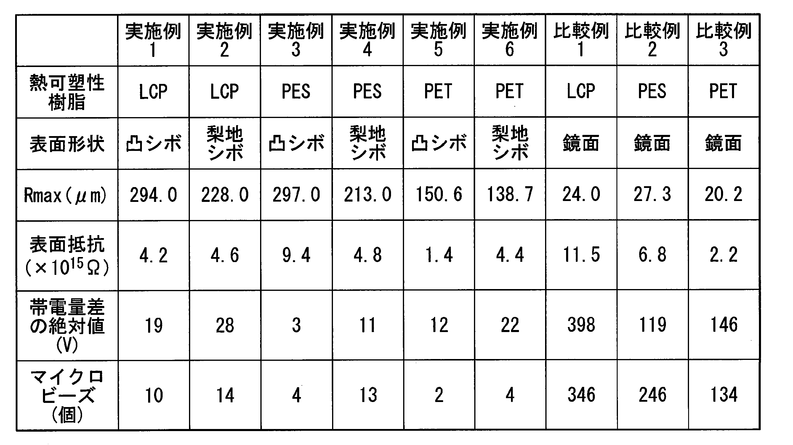
表1に示したように、表面粗さ(Rmax)が30μm以上500μm以下の範囲内である実施例1~6の射出成形品は、表面粗さ(Rmax)が30μm以上500μm以下の範囲外である比較例1~3の射出成形品と比べて帯電量の増加を抑制できることが示された。また、実施例1~6の射出成形品は、比較例1~3の射出成形品と比べて付着したマイクロビーズの個数が少なかった。一方、実施例1~6および比較例1~3の射出成形品においては、表面固有抵抗値(表面抵抗値)がほとんど変わらなかった。このことからも実施例1~6の射出成形品は、表面固有抵抗値が1015Ω以上を維持しながら帯電量の増加を抑制できることが示された。
以上の結果より、本発明が有用であることが確かめられた。
本発明によれば、帯電量の増加を抑制できる射出成形品および射出成形品の製造方法を提供できるので、産業上極めて有用である。
Claims (4)
- 電気・電子機器における筐体内装部品用の射出成形品であって、
熱可塑性樹脂から射出成形された1又は2以上の部品を含み、
厚さが、0.1mm以上であり、
表面抵抗が、1012Ω以上であり、
表面粗さが、最大高さ(Rmax)で30μm以上500μm以下である、
射出成形品。 - 前記筐体内装部品は、コネクター、カメラモジュール、送風ファンまたはプリンター向けの定着部品である請求項1に記載の射出成形品。
- 表面粗さが、最大高さ(Rmax)で30μm以上500μm以下である凸シボまたは梨地シボの凹凸形状を有する請求項1または2に記載の射出成形品。
- 請求項1~3のいずれか1項に記載の射出成形品の製造方法であって、
前記熱可塑性樹脂を含む射出成形用樹脂組成物を溶融させた後、金型内に射出する工程を含み、
前記金型の内表面は、凸シボまたは梨地シボに対応する凹凸形状を有する、射出成形品の製造方法。
Priority Applications (1)
| Application Number | Priority Date | Filing Date | Title |
|---|---|---|---|
| CN201780049276.0A CN109562550A (zh) | 2016-08-19 | 2017-08-10 | 注射成型品及注射成型品的制造方法 |
Applications Claiming Priority (2)
| Application Number | Priority Date | Filing Date | Title |
|---|---|---|---|
| JP2016161200A JP2018027661A (ja) | 2016-08-19 | 2016-08-19 | 射出成形品および射出成形品の製造方法 |
| JP2016-161200 | 2016-08-19 |
Publications (1)
| Publication Number | Publication Date |
|---|---|
| WO2018034229A1 true WO2018034229A1 (ja) | 2018-02-22 |
Family
ID=61196765
Family Applications (1)
| Application Number | Title | Priority Date | Filing Date |
|---|---|---|---|
| PCT/JP2017/029076 Ceased WO2018034229A1 (ja) | 2016-08-19 | 2017-08-10 | 射出成形品および射出成形品の製造方法 |
Country Status (4)
| Country | Link |
|---|---|
| JP (1) | JP2018027661A (ja) |
| CN (1) | CN109562550A (ja) |
| TW (1) | TW201811531A (ja) |
| WO (1) | WO2018034229A1 (ja) |
Cited By (1)
| Publication number | Priority date | Publication date | Assignee | Title |
|---|---|---|---|---|
| US20220243844A1 (en) * | 2019-07-17 | 2022-08-04 | Sumitomo Chemical Company, Limited | Method for manufacturing welded molding, welded molding, and pipe |
Citations (6)
| Publication number | Priority date | Publication date | Assignee | Title |
|---|---|---|---|---|
| JPS6418612A (en) * | 1987-07-13 | 1989-01-23 | Dainippon Printing Co Ltd | Ultra-high-molecular weight polyethylene molding and manufacture thereof |
| JPH08224762A (ja) * | 1994-12-20 | 1996-09-03 | Hitachi Ltd | 射出成形品、その製造方法、及びその金型 |
| JPH10337758A (ja) * | 1997-06-10 | 1998-12-22 | Nippon Steel Chem Co Ltd | ガラス繊維強化樹脂成形品及びその製造方法 |
| JP2003071884A (ja) * | 2001-09-04 | 2003-03-12 | Toray Ind Inc | 表面にシボを有するfrp成形品とその製造方法 |
| JP2003159562A (ja) * | 2001-11-27 | 2003-06-03 | Toray Ind Inc | 塗装樹脂成形品の製造方法およびその成形品 |
| JP2014042015A (ja) * | 2012-07-26 | 2014-03-06 | Mitsubishi Chemicals Corp | 太陽電池モジュール |
Family Cites Families (5)
| Publication number | Priority date | Publication date | Assignee | Title |
|---|---|---|---|---|
| EP1327917A1 (en) * | 2000-09-18 | 2003-07-16 | Suzuka Fuji Xerox Co., Ltd. | Transfer/fixing member for electrophotographic apparatus |
| CN100474139C (zh) * | 2005-09-16 | 2009-04-01 | 富士施乐株式会社 | 成像方法和成像装置 |
| JP2011133644A (ja) * | 2009-12-24 | 2011-07-07 | Canon Inc | 規制ブレード及びこれを用いた現像装置 |
| CN104067179B (zh) * | 2012-01-18 | 2016-05-18 | 佳能株式会社 | 电子照相用辊及其生产方法 |
| JP5892283B1 (ja) * | 2014-11-28 | 2016-03-23 | 住友化学株式会社 | 熱可塑性樹脂組成物からなる成形体 |
-
2016
- 2016-08-19 JP JP2016161200A patent/JP2018027661A/ja active Pending
-
2017
- 2017-08-10 WO PCT/JP2017/029076 patent/WO2018034229A1/ja not_active Ceased
- 2017-08-10 CN CN201780049276.0A patent/CN109562550A/zh active Pending
- 2017-08-16 TW TW106127756A patent/TW201811531A/zh unknown
Patent Citations (6)
| Publication number | Priority date | Publication date | Assignee | Title |
|---|---|---|---|---|
| JPS6418612A (en) * | 1987-07-13 | 1989-01-23 | Dainippon Printing Co Ltd | Ultra-high-molecular weight polyethylene molding and manufacture thereof |
| JPH08224762A (ja) * | 1994-12-20 | 1996-09-03 | Hitachi Ltd | 射出成形品、その製造方法、及びその金型 |
| JPH10337758A (ja) * | 1997-06-10 | 1998-12-22 | Nippon Steel Chem Co Ltd | ガラス繊維強化樹脂成形品及びその製造方法 |
| JP2003071884A (ja) * | 2001-09-04 | 2003-03-12 | Toray Ind Inc | 表面にシボを有するfrp成形品とその製造方法 |
| JP2003159562A (ja) * | 2001-11-27 | 2003-06-03 | Toray Ind Inc | 塗装樹脂成形品の製造方法およびその成形品 |
| JP2014042015A (ja) * | 2012-07-26 | 2014-03-06 | Mitsubishi Chemicals Corp | 太陽電池モジュール |
Cited By (1)
| Publication number | Priority date | Publication date | Assignee | Title |
|---|---|---|---|---|
| US20220243844A1 (en) * | 2019-07-17 | 2022-08-04 | Sumitomo Chemical Company, Limited | Method for manufacturing welded molding, welded molding, and pipe |
Also Published As
| Publication number | Publication date |
|---|---|
| JP2018027661A (ja) | 2018-02-22 |
| CN109562550A (zh) | 2019-04-02 |
| TW201811531A (zh) | 2018-04-01 |
Similar Documents
| Publication | Publication Date | Title |
|---|---|---|
| JP7269920B2 (ja) | 液晶ポリエステル組成物および成形品 | |
| JP5633338B2 (ja) | 液晶ポリエステル組成物 | |
| CN1377937B (zh) | 液晶聚酯树脂组合物 | |
| JP5914935B2 (ja) | 液晶ポリエステル組成物、液晶ポリエステル組成物の製造方法及び成形体 | |
| TWI583736B (zh) | 液晶聚酯樹脂組成物、連接器及液晶聚酯樹脂組成物之製造方法 | |
| CN102051029A (zh) | 液晶聚酯树脂组合物,模制品和用于光学拾取器透镜的支架 | |
| CN105377986A (zh) | 液晶聚酯组合物 | |
| KR20120046067A (ko) | 액정 폴리에스테르 조성물 | |
| CN108137907A (zh) | 照相机组件用液晶性聚酯树脂组合物及由其形成的照相机组件用成型品 | |
| TW201829582A (zh) | 液晶聚酯樹脂組成物 | |
| JP2011202062A (ja) | 摺動用熱可塑性樹脂組成物、摺動用熱可塑性樹脂組成物の製造方法および摺動部品 | |
| KR20120059382A (ko) | 액정 폴리에스테르 조성물 | |
| JP2011104789A (ja) | 金属複合積層部品の製造方法 | |
| WO2018034229A1 (ja) | 射出成形品および射出成形品の製造方法 | |
| WO2018174018A1 (ja) | 樹脂成形体の製造方法および樹脂成形体 | |
| KR20170117879A (ko) | 적층 필름, 적층 필름의 제조 방법 및 led 탑재 기판 | |
| TWI860308B (zh) | 透明導電性薄膜用基材及透明導電性薄膜 | |
| TW201228826A (en) | Mold release film | |
| JP2011112896A (ja) | 振動ミラー用台座および光走査装置 | |
| JP7668169B2 (ja) | 板状成形体 | |
| JP2018053070A (ja) | 液晶性樹脂組成物および成形品 | |
| JP2012210107A (ja) | 振動波モータ | |
| JP2024074425A (ja) | 筒状成形体 | |
| WO2012105468A1 (ja) | 積層シート及びその用途 | |
| TW202116860A (zh) | 液晶聚酯組成物及成形體 |
Legal Events
| Date | Code | Title | Description |
|---|---|---|---|
| 121 | Ep: the epo has been informed by wipo that ep was designated in this application |
Ref document number: 17841452 Country of ref document: EP Kind code of ref document: A1 |
|
| NENP | Non-entry into the national phase |
Ref country code: DE |
|
| 122 | Ep: pct application non-entry in european phase |
Ref document number: 17841452 Country of ref document: EP Kind code of ref document: A1 |