WO2018034112A1 - ピストンリング - Google Patents
ピストンリング Download PDFInfo
- Publication number
- WO2018034112A1 WO2018034112A1 PCT/JP2017/026804 JP2017026804W WO2018034112A1 WO 2018034112 A1 WO2018034112 A1 WO 2018034112A1 JP 2017026804 W JP2017026804 W JP 2017026804W WO 2018034112 A1 WO2018034112 A1 WO 2018034112A1
- Authority
- WO
- WIPO (PCT)
- Prior art keywords
- facing
- male
- peripheral surface
- piston ring
- outer peripheral
- Prior art date
- Legal status (The legal status is an assumption and is not a legal conclusion. Google has not performed a legal analysis and makes no representation as to the accuracy of the status listed.)
- Ceased
Links
Images


Classifications
-
- F—MECHANICAL ENGINEERING; LIGHTING; HEATING; WEAPONS; BLASTING
- F16—ENGINEERING ELEMENTS AND UNITS; GENERAL MEASURES FOR PRODUCING AND MAINTAINING EFFECTIVE FUNCTIONING OF MACHINES OR INSTALLATIONS; THERMAL INSULATION IN GENERAL
- F16J—PISTONS; CYLINDERS; SEALINGS
- F16J9/00—Piston-rings, e.g. non-metallic piston-rings, seats therefor; Ring sealings of similar construction
- F16J9/12—Details
- F16J9/14—Joint-closures
- F16J9/16—Joint-closures obtained by stacking of rings
-
- F—MECHANICAL ENGINEERING; LIGHTING; HEATING; WEAPONS; BLASTING
- F02—COMBUSTION ENGINES; HOT-GAS OR COMBUSTION-PRODUCT ENGINE PLANTS
- F02F—CYLINDERS, PISTONS OR CASINGS, FOR COMBUSTION ENGINES; ARRANGEMENTS OF SEALINGS IN COMBUSTION ENGINES
- F02F5/00—Piston rings, e.g. associated with piston crown
Definitions
- the present invention relates to a piston ring used in an internal combustion engine.
- Piston rings used in automobile internal combustion engines and the like are provided, for example, in a ring groove on the piston outer peripheral surface. Since the outer peripheral surface of the piston ring is in sliding contact with the inner peripheral surface of the bore and one side surface of the piston ring is in contact with the side surface of the ring groove, a function of preventing blow-by gas from the combustion chamber side to the crank chamber side is achieved. Since such a piston ring has a split ring shape having an abutment portion for the convenience of mounting in the ring groove, there is a problem of suppressing blow-by gas at the abutment portion.
- the piston ring described in Patent Document 1 discloses a piston ring having a special joint structure.
- one abutment end portion is provided with a protruding portion extending in the circumferential direction while forming a wedge shape whose cross section is narrowed radially inward.
- the other abutment end portion is provided with a recess serving as a receiving portion for the protruding portion.
- the sealing property of the blow-by gas is improved by ensuring the degree of adhesion between the mating surfaces of the protrusion and the recess.
- the piston ring when the piston ring is mounted in the ring groove on the outer peripheral surface of the piston, the piston ring is mounted in the ring groove by expanding the inner diameter of the ring beyond the outer diameter of the piston.
- the piston to which the piston ring is attached is inserted into the cylinder block in the engine assembly process.
- An object of the present invention is to provide a piston ring that can prevent breakage of the joint portion and can ensure good sealing performance.
- a piston ring is a piston ring including an annular main body portion having an inner peripheral surface and an outer peripheral surface facing each other, and a joint portion formed in the main body portion.
- a first projecting portion projecting from one abutment end portion toward the other abutment end portion, and a first receiving portion receiving the first projecting portion at the other abutment end portion;
- a second projection that projects from the other abutment end toward the one abutment end, and a second projection that receives the second projection at the one abutment end.
- a first male portion projecting from the second projecting portion toward the second receiving portion, and the first receiving portion in the second receiving portion.
- a first female part that receives the male part of the main body part is provided on the outer peripheral surface side of the main body part.
- a second male part projecting toward the first receiving part and a second female part receiving the second male part in the first receiving part are provided, and the first male part is the first male part.
- the second male part has an inclined surface or a convex curved surface that is inclined with respect to the mating surface with respect to the first female part and faces the outer peripheral surface side so that the tip of the male part is tapered.
- the second male portion has an inclined surface or a convex curved surface that is inclined with respect to the mating surface with respect to the second female portion and faces the inner peripheral surface side so that the tip of the second male portion is tapered.
- the tips of the first male part and the second male part are both tapered.
- the inclined surface or convex curved surface facing the outer peripheral surface side of the first male portion and the inclined surface or convex curved surface facing the inner peripheral surface side of the second male portion are a piston ring.
- cranks are formed by shifting each other.
- a position where the first male part and the first female part are opposed to each other on the inner peripheral surface side of the main body part, and a position where the second male part and the second female part are opposed to each other on the outer peripheral surface side of the main body part. Are shifted from each other, so that a crank different from the crank is formed.
- the first male part may have an inclined surface facing the outer peripheral surface side
- the second male part may have an inclined surface facing the inner peripheral surface side.
- the first male part may have a convex curved surface facing the outer peripheral surface side
- the second male part may have a convex curved surface facing the inner peripheral surface side. In this case, the catch of the first male part and the second male part can be satisfactorily suppressed.
- the first male part is a mating surface for the first female part, has a tip surface extending perpendicularly to the circumferential direction
- the second male part is a mating surface for the second female part.
- the distal ends of the first male part and the second male part have a thickness corresponding to the distal end surface. For this reason, the intensity
- a first facing surface facing an inclined surface or a convex curved surface facing the outer peripheral surface of the first male portion is formed in the first corner formed by the first female portion and the second male portion. Is provided at the second corner formed by the second female portion and the first male portion on an inclined surface or a convex curved surface facing the inner peripheral surface of the second male portion.
- a second opposing surface is provided, the first opposing surface is a concave curved surface or plane facing the inner peripheral surface side, and the second opposing surface is a concave curved surface facing the outer peripheral surface side. It may be a plane or a plane.
- the gap between the inclined surface or the curved surface of the first male portion and the first opposing surface, the inclined surface or the curved surface of the second male portion, and the second opposing surface Can be narrowed. Thereby, accumulation of sludge etc. in the gap can be suppressed.
- the first opposing surface may be a concave curved surface facing the inner peripheral surface side
- the second opposing surface may be a concave curved surface facing the outer peripheral surface side.
- the first facing surface may be a plane facing the inner peripheral surface side
- the second facing surface may be a plane facing the outer peripheral surface side
- a piston ring according to another aspect of the present invention is a piston ring including an annular main body portion having an inner peripheral surface and an outer peripheral surface facing each other, and a joint portion formed in the main body portion.
- the first projecting portion projecting from one abutment end portion toward the other abutment end portion and the first receiving portion receiving the first projecting portion at the other abutment end portion are provided on one side of the main body portion.
- a second receiving portion is provided, and on the outer peripheral surface side of the main body portion, a first male portion protruding from the second protruding portion toward the second receiving portion, and a second receiving portion at the second receiving portion
- a first female part that receives one male part, and a first protrusion on the inner peripheral surface side of the main body part
- the second male part has an inclined surface or a convex curved surface that is inclined with respect to the mating surface with respect to the first female part and faces the inner peripheral surface side so that the tip of the male part is tapered.
- the tips of the first male part and the second male part are both tapered.
- the inclined surface or convex curved surface facing the inner peripheral surface side of the first male part and the inclined surface or convex curved surface facing the outer peripheral surface side of the second male part are a piston ring.
- cranks are formed by shifting each other.
- a position where the first male part and the first female part face each other on the outer peripheral surface side of the main body part, and a position where the second male part and the second female part face each other on the inner peripheral surface side of the main body part. Are shifted from each other, so that a crank different from the crank is formed.
- the first male part may have an inclined surface facing the inner peripheral surface side
- the second male part may have an inclined surface facing the outer peripheral surface side.
- the first male part may have a convex curved surface facing the inner peripheral surface side
- the second male part may have a convex curved surface facing the outer peripheral surface side. In this case, the catch of the first male part and the second male part can be satisfactorily suppressed.
- the first male part is a mating surface for the first female part, has a tip surface extending perpendicularly to the circumferential direction
- the second male part is a mating surface for the second female part.
- the distal ends of the first male part and the second male part have a thickness corresponding to the distal end surface. For this reason, the intensity
- the first opposing part faces the inclined surface or convex curved surface facing the inner peripheral surface of the first male part.
- the second female corner and the first male part are formed on an inclined surface or a convex curved surface facing the outer peripheral surface of the second male part.
- a second opposing surface is provided, the first opposing surface being a concave curved surface or plane facing the outer peripheral surface side, and the second opposing surface being a concave curved surface facing the inner peripheral surface side. It may be a plane or a plane.
- the gap between the inclined surface or the curved surface of the first male portion and the first opposing surface, the inclined surface or the curved surface of the second male portion, and the second opposing surface. Can be narrowed. Thereby, accumulation of sludge etc. in the gap can be suppressed.
- the first opposing surface may be a concave curved surface facing the outer peripheral surface side
- the second opposing surface may be a concave curved surface facing the inner peripheral surface side
- the first facing surface may be a plane facing the outer peripheral surface side
- the second facing surface may be a plane facing the inner peripheral surface side
- a surface treatment film may be provided on at least one of the mating surface, the inclined surface, and the convex curved surface with respect to the female portion. In this case, the main body can be protected by the surface treatment film.
- the main body may be made of metal or alloy. Thereby, sufficient heat resistance of the piston ring can be ensured.
- the main body may be formed of a heat-resistant resin composition. Thereby, a joint part can be processed easily, ensuring the heat resistance of a piston ring.
- the resin composition may contain a filler for improving heat resistance. Thereby, sufficient heat resistance of the piston ring can be ensured.
- the piston ring According to the piston ring according to one aspect of the present invention, it is possible to suppress breakage of the abutment portion and to ensure good sealing performance.
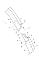
- FIG. 1 is a perspective view showing a first embodiment of a piston ring according to an aspect of the present invention.
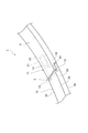
- FIG. 2 is an enlarged perspective view of a main part of the joint portion of the piston ring shown in FIG.
- FIG. 3 is an enlarged perspective view of a main part showing a joint portion of the piston ring shown in FIG. 1 from one side surface side.
- FIG. 4 is an enlarged perspective view of a main part showing the joint portion of the piston ring shown in FIG. 1 from the other side surface side.
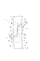
- FIG. 5 is an enlarged view of a main part when the joint portion of the piston ring shown in FIG. 1 is viewed from the other side surface.
- FIG. 2 is an enlarged perspective view of a main part of the joint portion of the piston ring shown in FIG.
- FIG. 3 is an enlarged perspective view of a main part showing a joint portion of the piston ring shown in FIG. 1 from one side surface side.
- FIG. 4 is an enlarged perspective view of a main part showing the joint
- FIG. 6A is an enlarged perspective view of a main part showing a reduced diameter of the piston ring according to the comparative example
- FIG. 6B is a main part showing a reduced diameter of the piston ring according to the first embodiment.
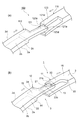
- FIG. 7A is an enlarged view of the main part of the piston ring joint in a free state as viewed from the outer peripheral surface side
- FIG. 7B shows the piston ring joint after assembly to the piston on the outer peripheral surface. It is the principal part enlarged view seen from the side.
- FIG. 8 is an enlarged view of a main part when a joint portion of a piston ring according to a modification of the first embodiment is viewed from the other side surface.
- FIG.9 (a) is the principal part enlarged view which looked at the joint part of the piston ring of 2nd Embodiment from the other side surface
- FIG.9 (b) is the joint of the piston ring of the modification of 2nd Embodiment. It is the principal part enlarged view which looked at the part from the other side surface side.
- FIG. 1 is a perspective view showing a first embodiment of a piston ring according to an aspect of the present invention.
- a piston ring 1 shown in the figure is provided in a ring groove on an outer peripheral surface of a piston in an internal combustion engine of an automobile, for example.
- the blow-by gas from the combustion chamber side to the crank chamber side is obtained when the outer peripheral surface 2d of the piston ring 1 is in sliding contact with the inner peripheral surface of the bore and the side surface 2b of the piston ring 1 is in contact with the side surface of the ring groove to form a seal surface
- the function of preventing this is achieved.
- the piston ring 1 includes an annular main body 2 and a joint portion 3 formed in a part of the main body 2.
- the main body 2 has a long side in the thickness direction by a side surface 2a (one side surface) and a side surface 2b (other side surface) which are end surfaces in the width direction, and an inner peripheral surface 2c and an outer peripheral surface 2d which are end surfaces in the thickness direction.
- the cross section has a substantially rectangular shape with a short side in the width direction.
- the main body 2 is formed of a metal or an alloy (a cast iron or steel material containing a plurality of metal elements) with sufficient strength, heat resistance, and elasticity.
- a surface treatment film is provided on the surface of the main body 2.
- the surface treatment film is, for example, a hard film such as a hard chromium plating layer, a PVD treatment layer, a nitride layer such as iron or chromium, or a DLC (diamond-like carbon) film.
- a hard film such as a hard chromium plating layer, a PVD treatment layer, a nitride layer such as iron or chromium, or a DLC (diamond-like carbon) film.
- FIGS. 2 to 4 is an enlarged perspective view of a main part showing the joint portion 3 of the piston ring 1 shown in FIG. 1 from the side surface 2a.
- the abutment portion 3 is a cut formed in a part of the main body portion 2 for the purpose of securing the mountability when the piston ring 1 is mounted in the ring groove on the piston outer peripheral surface. Is provided.
- one abutment end portion 11 and the other abutment end portion 12 face each other with a predetermined interval before the piston ring 1 is mounted in the ring groove.
- a first projecting portion projecting from one joint end portion 11 toward the other joint end portion 12 on the side surface 2a side of the main body 2 is provided.
- 13 and a first receiving portion 14 that receives the first protruding portion 13 at the other joint end portion 12 are provided.
- a second projecting portion 15 projecting from the other joint end portion 12 toward the one joint end portion 11, and a second projecting portion at the one joint end portion 11. 15 and a second receiving portion 16 that receives 15 is provided on the side surface 2 b side of the main body 2.
- a substantially half portion on the side surface 2 a side of the main body 2 is projected from the one end portion 11 in a substantially rectangular shape. Further, in the first projecting portion 13, the tip angle on the side surface 2 b facing the first receiving portion 14 is notched. As a result, a notch surface S1 is formed at the tip of the first protrusion 13 on the side of the side surface 2b facing the first receiving portion 14.
- a state in which a substantially half portion on the side surface 2 a side of the main body portion 2 is cut out into a substantially rectangular cross section corresponding to the shape of the first protruding portion 13 in the other joint end portion 12. It has become.
- a front end surface 13a that is a surface facing the first receiving portion 14 in the first protrusion 13 and a front end surface 14a that is a surface facing the first protruding portion 13 in the first receiving portion 14 are respectively in the circumferential direction. On the other hand, it has a substantially rectangular shape extending vertically or substantially vertically.
- the substantially half part by the side surface 2b side of the main-body part 2 is in the state which protruded in cross-sectional substantially rectangular shape from the other abutment edge part 12.
- the tip angle on the side surface 2 a facing the second receiving portion 16 is notched.
- a notch surface S ⁇ b> 2 is formed at the tip on the side surface 2 a facing the second receiving portion 16 in the second protrusion 15.
- a first male part 21 projecting from the second projecting part 15 toward the second receiving part 16;
- Two receiving portions 16 are provided with a first female portion 22 that receives the first male portion 21.
- a second male portion 23 that protrudes from the second receiving portion 16 toward the second protrusion portion 15, and a second A second female portion 24 that receives the second male portion 23 is provided in the protruding portion 15.
- a so-called step joint is formed by the first male part 21, the first female part 22, the second male part 23, and the second female part 24.
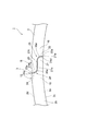
- FIG. 5 is an enlarged view of a main part of the joint portion 3 as viewed from the side surface 2b.
- the first male portion 21 is in a state in which a substantially half portion of the second protruding portion 15 on the inner peripheral surface 2 c side protrudes.
- the first male portion 21 is inclined with respect to the mating surface 21a so that the mating surface 21a with respect to the first female portion 22 and the tip of the first male portion 21 are tapered, and And an inclined surface 21b facing the outer peripheral surface 2d side.
- the mating surface 21a is a distal end surface that is positioned on the inner peripheral surface 2c side of the first male portion 21 with respect to the inclined surface 21b and extends perpendicular to the circumferential direction.
- One end of the mating surface 21a and the inner peripheral surface 2c form a right angle.
- the inclined surface 21b is a plane connected to the end of the mating surface 21a on the outer peripheral surface 2d side, and is formed, for example, by cutting out a corner on the outer peripheral surface 2d side of the first male portion 21.
- the mating surface 21a and the inclined surface 21b form an obtuse angle.
- the angle formed by the mating surface 21a and the inclined surface 21b is, for example, 110 ° or more or 120 ° or more, and is 170 ° or less, 160 ° or less, or 150 ° or less.
- the proportion of the inclined surface 21b is, for example, 0.1 times or more, 0.2 times or more, or 0.5 times or more of the proportion of the mating surface 21a, 100 times or less, 50 times or less, or 35 times or less.
- the second male part 23 is in a state in which a substantially half part on the outer peripheral surface 2d side of the second receiving part 16 protrudes.
- the second male portion 23 is inclined with respect to the mating surface 23a so that the mating surface 23a with respect to the second female portion 24 and the tip of the second male portion 23 are tapered, and And an inclined surface 23b facing the inner peripheral surface 2c.
- the mating surface 23a is a distal end surface that is positioned on the distal end side of the second male portion 23 and on the outer circumferential surface 2d side with respect to the inclined surface 23b, and extends perpendicular to the circumferential direction.
- One end of the mating surface 23a and the outer peripheral surface 2d form a right angle.
- the inclined surface 23b is a plane connected to the end on the inner peripheral surface 2c side of the mating surface 23a, and is formed by cutting out a corner portion on the inner peripheral surface 2c side in the second male portion 23, for example.
- the mating surface 23a and the inclined surface 23b form an obtuse angle.
- the angle formed by the mating surface 23a and the inclined surface 23b is, for example, 110 or more or 120 ° or more, and is 170 ° or less, 160 ° or less, or 150 ° or less.
- the proportion of the inclined surface 23b is, for example, 0.1 times or more, 0.2 times or more, or 0.5 times or more of the proportion of the mating surface 23a, 100 times or less, 50 times or less, or 35 times or less.
- the first female portion 22 is in a state in which a substantially half portion on the inner peripheral surface 2c side of the second receiving portion 16 is cut out so as not to contact the first male portion 21.
- a first entry corner 25 formed by the first female part 22 and the second male part 23 is provided with a facing surface 25a (first facing surface) that faces the inclined surface 21b.
- the facing surface 25 a forms a concave curved surface facing the inner peripheral surface 2 c, the mating surface 23 c of the second male part 23 with respect to the first male part 21, and the first female part 22 first.
- the mating surface 22a with respect to the male part 21 is smoothly connected.
- the second female part 24 is in a state where a substantially half part on the outer peripheral surface 2d side of the second projecting part 15 is cut out so as not to contact the second male part 23.
- the second corner portion 26 formed by the second female portion 24 and the first male portion 21 is provided with a facing surface 26a (second facing surface) that faces the inclined surface 23b.
- the facing surface 26 a forms a concave curved surface facing the outer peripheral surface 2 d side, the mating surface 21 c of the first male portion 21 with respect to the second male portion 23, and the second female portion 24.
- the mating surface 24a with respect to the male part 23 is smoothly connected.
- the base end side of the 1st male part 21 which makes the 2nd inside corner part 26 is thicker than the front end side of the 1st male part 21, the base end side of the 1st male part 21 Strength against breakage (breakage strength) is increasing.
- FIG. 6A is an enlarged perspective view of a main part showing a reduced diameter of the piston ring according to the comparative example
- FIG. 6B is a main view showing a reduced diameter of the piston ring 1 according to the first embodiment.
- the piston inner ring is attached to the ring groove by expanding the inner diameter of the ring beyond the outer diameter of the piston.
- the piston to which the piston ring is attached is inserted into the cylinder block in the engine assembly process.
- the piston ring is reduced in diameter to the cylinder inner diameter so as not to prevent the piston ring from being inserted into the cylinder block.
- the diameter reduction of a piston ring is implemented using jigs, such as a taper cone, for example.
- the first male part 121 does not have the inclined surface 21b, and the second male part 123 has the inclined surface 23b. Does not have.
- the corner 121d is provided at the tip of the first male part 121 on the outer peripheral surface 2d side, and the corner 123d is provided at the tip of the second male part 123 on the inner peripheral surface 2c side. Yes.
- the corner portion 121d of the first male portion 121 collides with the tip surface 123a of the second male portion 123, and the corner portion 121d.
- the tips of the first male part 21 and the second male part 23 are both tapered.
- the inclined surface 21 b of the first male part 21 and the inclined surface 23 b of the second male part 23 are provided so as to face each other in the thickness direction of the piston ring 1.
- the inclined surfaces 21b and 23b since the inclined surfaces 21b and 23b not provided with the corners collide with each other, the first male part 21 and the second male part 23 are not easily caught. In addition, since the inclined surfaces 21b and 23b are in surface contact with each other at the time of the collision, stress concentration is less likely to occur. Therefore, the breakage of the joint portion 3 can be satisfactorily suppressed. Furthermore, the inclined surfaces 21b and 23b slide according to the force applied when the diameter of the piston ring 1 is reduced, and the piston ring 1 can be easily closed.
- crank C ⁇ b> 1 is formed by the mating surface 23 a, the inclined surface 23 b, and the mating surface 24 a of the second female portion 24.
- the mating surface 21c of the first male portion 21 with respect to the second male portion 23 and the mating surface 23c of the second male portion 23 with respect to the first male portion 21 are in use when the piston ring 1 is used. Less susceptible to temperature expansion. Further, even when a load due to the vertical movement of the piston is applied to the piston ring 1, the load is hardly applied in the facing direction of the mating surfaces 21c and 23c, and the influence of wear is small, so the interval between the mating surfaces 21c and 23c is kept small. be able to. Therefore, it is possible to minimize the gas flow area in the crank C1, and it is possible to suppress the gas that has circulated to the inner peripheral surface 2c side of the piston ring 1 from passing through the crank C1 to the outer peripheral surface 2d side. .
- FIG. 7A is an enlarged view of the main part of the joint portion 3 of the piston ring 1 in the free state as viewed from the outer peripheral surface 2d side
- FIG. 7B is the joint portion of the piston ring 1 after being assembled to the piston. It is the principal part enlarged view which looked at the part 3 from the outer peripheral surface 2d side.
- FIG. 7 (b) when the piston ring 1 is mounted in the ring groove on the outer peripheral surface of the piston, the first projecting portion 13 and the first receiving portion 14 are opposed to each other on the side surface 2a side of the main body portion 2.
- the first male part 21 is a mating surface 21a with respect to the first female part 22 and has a distal end surface extending perpendicularly to the circumferential direction
- the second male part 23 is a second female part.
- 24 is a mating surface 23a, and has a front end surface extending perpendicularly to the circumferential direction.
- tip of the 1st male part 21 and the 2nd male part 23 has the thickness corresponded to the mating surfaces 21a and 23a mutually.
- tip of the 1st male part 21 and the 2nd male part 23 can be ensured, and the damage of the joint part 3 can be suppressed favorably.
- the first corner portion 25 formed by the first female portion 22 and the second male portion 23 is provided with a facing surface 25a facing the inclined surface 21b of the first male portion 21, and the second
- the second inner corner portion 26 formed by the female portion 24 and the first male portion 21 is provided with a facing surface 26a facing the inclined surface 23b of the second male portion 23, and the facing surface 25a is
- the concave curved surface facing the inner peripheral surface 2c side and the opposing surface 26a may be a concave curved surface facing the outer peripheral surface 2d side.
- the clearance gap between the inclined surface 21b and the opposing surface 25a which the 1st male part 21 has, and the clearance gap between the inclined surface 23b and the opposing surface 26a which the 2nd male part 23 has can be narrowed. Thereby, accumulation of sludge etc. in the gap can be suppressed.
- a surface treatment film may be provided on at least one of the side surfaces 2a, 2b, the inner peripheral surface 2c, and the outer peripheral surface 2d. In this case, the main body 2 can be protected by the surface treatment film.
- the main body 2 may be formed of a metal or an alloy. Thereby, sufficient heat resistance of the piston ring 1 can be ensured.
- the 1st male part 21 has the inclined surface 21b, for example, as shown in FIG. 8, in a modification, the 1st male part 21 is with respect to the mating surface 21a. And may have a convex curved surface 21d that is inclined and faces the outer peripheral surface 2d side. Similarly, in the modification, the second male portion 23 may have a convex curved surface 23d that is inclined with respect to the mating surface 23a and faces the inner peripheral surface 2c instead of the inclined surface 23b. Good.
- the first male portion 21 and the second male portion 23 can be easily caught when the piston ring 1 is mounted in the ring groove on the piston outer peripheral surface. Can be suppressed.
- the gap between the curved surface 21d of the first male part 21 and the facing surface 25a of the first corner 25 can be further reduced, and the second male part Since the gap between the curved surface 23d of 23 and the facing surface 26a of the second corner 26 can be further narrowed, accumulation of sludge and the like in the gap can be satisfactorily suppressed.
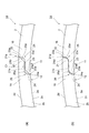
- FIG. 9A is an enlarged view of a main part of the joint portion of the piston ring according to the second embodiment as viewed from the other side surface.
- the piston ring 1 ⁇ / b> A shown in FIG. 9 (a) has the first male part 21, the first female part 22, the second male part 23, and the position where the second female part 24 is provided. It differs from the piston ring 1 of one embodiment. Specifically, on the side surface 2b side of the main body portion 2, on the outer peripheral surface 2d side of the main body portion 2, a first male portion 21 protruding from the second protrusion portion 15 toward the second receiving portion 16 and In the second receiving part 16, a first female part 22 that receives the first male part 21 is provided.
- a second male part 23 protruding from the second receiving part 16 toward the second protruding part 15;
- a second female portion 24 that receives the second male portion 23 is provided in the two protruding portions 15.
- the first male portion 21 in the piston ring 1A has an inclined surface 21b that is inclined with respect to the mating surface 22a with respect to the first female portion 22 and directed toward the inner peripheral surface 2c so that the tip thereof is tapered. is doing.
- the second male portion 23 has an inclined surface 23b that is inclined with respect to the mating surface 24a with respect to the second female portion 24 and directed toward the outer peripheral surface 2d so that the tip thereof is tapered.
- the facing surface 25a provided in the first corner portion 25 formed by the first female portion 22 and the second male portion 23 forms a concave curved surface facing the outer peripheral surface 2d side.
- the opposing surface 26a provided in the second corner 26 formed by the two female portions 24 and the first male portion 21 forms a concave curved surface facing the inner peripheral surface 2c.
- FIG. 9B is an enlarged view of a main part when the joint portion of the piston ring of the modified example of the second embodiment is viewed from the other side surface.
- the first male part 21 of the modification shown in FIG. 9B may have a convex curved surface 21d that is inclined with respect to the mating surface 21a and faces the inner peripheral surface 2c.
- the second male portion 23 may have a convex curved surface 23d that is inclined with respect to the mating surface 23a and faces the outer peripheral surface 2d, instead of the inclined surface 23b. .
- the present invention is not limited to the first and second embodiments.
- the main body 2 is formed of a metal or an alloy.
- the piston ring is made of a resin composition such as a synthetic resin.
- One main body 2 may be formed.
- the piston ring 1 may be formed of a resin composition having heat resistance.
- the resin composition having heat resistance is, for example, polyimide (PI), polyamideimide (PAI), polytetrafluoroethylene (PTFE), polybenzimidazole (PBI), polyetherketoneketone (PEEK), polyetherketone.
- the resin composition may contain a filler for improving heat resistance. Thereby, sufficient heat resistance of the piston ring 1 can be ensured.
- the facing surface 25a of the first corner 25 is a concave curved surface facing the inner peripheral surface 2c, but is not limited thereto.
- the facing surface 25a may be a flat surface facing the inner peripheral surface 2c.
- the opposing surface 25 a is an inclined surface that is inclined with respect to the mating surface 22 a of the first female portion 22 with respect to the first male portion 21, and the mating surface 22 a and the first of the second male portion 23.
- the mating surface 23c with respect to the male part 21 is connected.
- the facing surface 26a of the second corner 26 may be a flat surface facing the outer peripheral surface 2d side.
- the facing surface 26 a is an inclined surface that is inclined with respect to the mating surface 24 a with respect to the second male portion 23 of the second female portion 24, and the mating surface 24 a and the second of the first male portion 21.
- the mating surface 21c with respect to the male part 23 is connected.
- the facing surface 25a may be a flat surface facing the outer peripheral surface 2d
- the facing surface 26a may be a flat surface facing the inner peripheral surface 2c.
- the 1st male part 21 has the inclined surface 21b and the 2nd male part 23 has the inclined surface 23b, it is not restricted to this.
- the first male part 21 may have an inclined surface 21b, while the second male part 23 may have a convex curved surface 23d.
- the first male part 21 may have a convex curved surface 21d, while the second male part 23 may have an inclined surface 23b.
- the facing surface 25a of the first corner portion 25 is a concave curved surface facing the inner peripheral surface 2c side, and the facing surface 26a of the second corner portion 26 faces the outer peripheral surface 2d side.
- the concave curved surface which faces it is not restricted to this.
- the opposing surface 25a of the first corner 25 is a concave curved surface facing the inner circumferential surface 2c, while the facing surface 26a of the second corner 26 is a plane facing the outer circumferential surface 2d. Good.
- the opposing surface 25a of the first corner 25 is a flat surface facing the inner circumferential surface 2c
- the facing surface 26a of the second corner 26 is a concave curved surface facing the outer circumferential surface 2d.
- the opposing surface 25a is a concave curved surface which faces the outer peripheral surface 2d side
- the opposing surface 26a may be a plane which faces the inner peripheral surface 2c side
- the opposing surface 25a is an outer peripheral surface.
- the facing surface 26a may be a concave curved surface facing the inner peripheral surface 2c side.
- the mating surface 21a is a tip surface that extends perpendicular to the circumferential direction, but is not limited thereto.
- the mating surface 21a may be an inclined surface that forms an acute angle with the inclined surface 21b, or may be a part of the curved surface 21d.
- the mating surface 23a may be an inclined surface that forms an acute angle with the inclined surface 23b, or may be a part of the curved surface 23d.
- the surface of the main body 2 is the side surfaces 2a and 2b, the inner peripheral surface 2c, and the outer peripheral surface 2d, but is not limited thereto.
- the surface of the main body part 2 may include each surface constituting the joint part 3.
- the front surfaces 13a, 14a, 15a, and 16a, the mating surfaces 13b, 15b, 21a, 21c, 22a, 23a, 23c, and 24a, the inclined surfaces 21b and 23b, and the curved surface 21d are referred to as the surfaces that constitute the joint portion 3. , 23d, opposed surfaces 25a, 26a, and cutout surfaces S1, S2.
- a surface treatment film may be provided on at least one of the surfaces constituting the joint portion 3. In this case, it is possible to satisfactorily suppress the breakage of the main body 2 constituting the joint portion 3.
- the side surface 2a is disposed on the combustion chamber side of the piston, and the side surface 2b is disposed on the crank chamber side of the piston. Also good.
- the mating surface 21c of the first male part 21 with respect to the second male part 23 and the mating surface 23c of the second male part 23 with respect to the first male part 21 are not easily affected by temperature expansion, and the piston The influence of wear during use of the ring 1 is also reduced. For this reason, the space
- the side surface 2a is disposed on the crank chamber side of the piston, and the side surface 2b is disposed on the combustion chamber side of the piston. Also good. In this case, oil consumption can be satisfactorily suppressed by the piston ring 1, so that oil consumption can be reduced.
- the piston ring 1 has a substantially rectangular cross section, but is not limited thereto.
- the cross-sectional shape of the piston ring 1 may have a keystone shape, a tapered shape, or a barrel face shape.
- convex curve Surface 22 ... first female part, 23 ... second male part, 23a ... mating surface (tip face), 23b ... inclined surface, 23d ... convex curved surface, 24 ... second female part, 25 ... First entrance corner, 25a ... opposing surface (first opposing surface), 26 ... second entrance corner, 26a ... opposing surface (second opposing surface), C , C2 ... Crank, S1, S2 ... truncated face.
Landscapes
- Engineering & Computer Science (AREA)
- General Engineering & Computer Science (AREA)
- Mechanical Engineering (AREA)
- Chemical & Material Sciences (AREA)
- Combustion & Propulsion (AREA)
- Pistons, Piston Rings, And Cylinders (AREA)
Priority Applications (3)
| Application Number | Priority Date | Filing Date | Title |
|---|---|---|---|
| EP17841340.7A EP3499095A4 (en) | 2016-08-15 | 2017-07-25 | PISTON RING |
| US16/325,390 US20190195363A1 (en) | 2016-08-15 | 2017-07-25 | Piston ring |
| CN201780049706.9A CN109563930A (zh) | 2016-08-15 | 2017-07-25 | 活塞环 |
Applications Claiming Priority (2)
| Application Number | Priority Date | Filing Date | Title |
|---|---|---|---|
| JP2016159288A JP2018028332A (ja) | 2016-08-15 | 2016-08-15 | ピストンリング |
| JP2016-159288 | 2016-08-15 |
Publications (1)
| Publication Number | Publication Date |
|---|---|
| WO2018034112A1 true WO2018034112A1 (ja) | 2018-02-22 |
Family
ID=61196549
Family Applications (1)
| Application Number | Title | Priority Date | Filing Date |
|---|---|---|---|
| PCT/JP2017/026804 Ceased WO2018034112A1 (ja) | 2016-08-15 | 2017-07-25 | ピストンリング |
Country Status (5)
| Country | Link |
|---|---|
| US (1) | US20190195363A1 (enExample) |
| EP (1) | EP3499095A4 (enExample) |
| JP (1) | JP2018028332A (enExample) |
| CN (1) | CN109563930A (enExample) |
| WO (1) | WO2018034112A1 (enExample) |
Families Citing this family (4)
| Publication number | Priority date | Publication date | Assignee | Title |
|---|---|---|---|---|
| USD920408S1 (en) * | 2018-09-25 | 2021-05-25 | Kabushiki Kaisha Riken | Piston ring for internal combustion engine |
| EP4008933A1 (de) * | 2020-12-04 | 2022-06-08 | Burckhardt Compression AG | Kolbenring für einen kolbenverdichter |
| KR102659819B1 (ko) * | 2021-09-29 | 2024-04-23 | 두산에너빌리티 주식회사 | 씰링 어셈블리 및 이를 포함하는 터보머신 |
| US20250163818A1 (en) * | 2023-11-22 | 2025-05-22 | Rtx Corporation | Piston ring seal |
Citations (5)
| Publication number | Priority date | Publication date | Assignee | Title |
|---|---|---|---|---|
| JPS55180044U (enExample) * | 1979-06-08 | 1980-12-24 | ||
| JPS59224446A (ja) * | 1983-05-30 | 1984-12-17 | Teikoku Piston Ring Co Ltd | 樹脂製ピストンリングおよび樹脂製ピストンリングとシリンダとの組合せ |
| JPH0533865A (ja) * | 1991-07-26 | 1993-02-09 | Riken Corp | 内燃機関のピストンリング装置 |
| JPH09159026A (ja) * | 1995-12-08 | 1997-06-17 | Rongu Well Japan Kk | ピストンリング |
| JP2007192242A (ja) * | 2006-01-17 | 2007-08-02 | Mitsui Chemicals Inc | 溶融成形可能な熱可塑性ポリイミド樹脂からなるピストンリング |
Family Cites Families (7)
| Publication number | Priority date | Publication date | Assignee | Title |
|---|---|---|---|---|
| US1367710A (en) * | 1917-07-09 | 1921-02-08 | Edward R Norman | Piston-ring |
| US2092413A (en) * | 1934-06-22 | 1937-09-07 | Westinghouse Air Brake Co | Piston ring joint |
| JPH017888Y2 (enExample) * | 1980-12-18 | 1989-03-02 | ||
| JPH0674339A (ja) * | 1992-08-28 | 1994-03-15 | Nippon Piston Ring Co Ltd | 圧力リング |
| JP3324887B2 (ja) * | 1994-11-08 | 2002-09-17 | 本田技研工業株式会社 | 油圧シール装置 |
| US5934680A (en) * | 1995-05-31 | 1999-08-10 | Ntn Corporation | Split resin seal ring with chamfered end connection structures |
| CN201193698Y (zh) * | 2008-03-25 | 2009-02-11 | 陈郁传 | 一种横竖拦截活塞环 |
-
2016
- 2016-08-15 JP JP2016159288A patent/JP2018028332A/ja active Pending
-
2017
- 2017-07-25 CN CN201780049706.9A patent/CN109563930A/zh active Pending
- 2017-07-25 WO PCT/JP2017/026804 patent/WO2018034112A1/ja not_active Ceased
- 2017-07-25 EP EP17841340.7A patent/EP3499095A4/en not_active Withdrawn
- 2017-07-25 US US16/325,390 patent/US20190195363A1/en not_active Abandoned
Patent Citations (5)
| Publication number | Priority date | Publication date | Assignee | Title |
|---|---|---|---|---|
| JPS55180044U (enExample) * | 1979-06-08 | 1980-12-24 | ||
| JPS59224446A (ja) * | 1983-05-30 | 1984-12-17 | Teikoku Piston Ring Co Ltd | 樹脂製ピストンリングおよび樹脂製ピストンリングとシリンダとの組合せ |
| JPH0533865A (ja) * | 1991-07-26 | 1993-02-09 | Riken Corp | 内燃機関のピストンリング装置 |
| JPH09159026A (ja) * | 1995-12-08 | 1997-06-17 | Rongu Well Japan Kk | ピストンリング |
| JP2007192242A (ja) * | 2006-01-17 | 2007-08-02 | Mitsui Chemicals Inc | 溶融成形可能な熱可塑性ポリイミド樹脂からなるピストンリング |
Non-Patent Citations (1)
| Title |
|---|
| See also references of EP3499095A4 * |
Also Published As
| Publication number | Publication date |
|---|---|
| EP3499095A4 (en) | 2020-04-22 |
| US20190195363A1 (en) | 2019-06-27 |
| EP3499095A1 (en) | 2019-06-19 |
| CN109563930A (zh) | 2019-04-02 |
| JP2018028332A (ja) | 2018-02-22 |
Similar Documents
| Publication | Publication Date | Title |
|---|---|---|
| JP6615833B2 (ja) | シールリング | |
| WO2018034112A1 (ja) | ピストンリング | |
| JP6192524B2 (ja) | ピストンリング | |
| JP6447667B2 (ja) | シールリング及び密封構造 | |
| JP2020046077A (ja) | シールリング | |
| JP4901806B2 (ja) | ピストンリング | |
| JP5867158B2 (ja) | 密封構造 | |
| JP4816562B2 (ja) | オイルシール構造 | |
| JP2017036750A (ja) | 2分割止め輪 | |
| JP5409584B2 (ja) | 組合せピストンリング | |
| JP6579813B2 (ja) | ピストンリング | |
| WO2016143397A1 (ja) | 密封装置 | |
| JP2011137384A (ja) | 回転防止用2ピースオイルリング | |
| JP5891285B1 (ja) | オイルリング | |
| JP2017198343A (ja) | ピストンリング | |
| JP5598000B2 (ja) | シールリング | |
| JP3548703B2 (ja) | 内燃機関のピストンリング | |
| JP6711505B2 (ja) | コンプレッションリング | |
| JP2010276091A (ja) | ピストンリング | |
| JP2019100379A (ja) | ピストンリングセット | |
| JP2004100743A (ja) | シールリング | |
| JP2017101736A (ja) | シールリング | |
| WO2020158479A1 (ja) | バルブステムシール | |
| JP2011117502A (ja) | ピストンリング | |
| JP2009150454A (ja) | パッキン |
Legal Events
| Date | Code | Title | Description |
|---|---|---|---|
| 121 | Ep: the epo has been informed by wipo that ep was designated in this application |
Ref document number: 17841340 Country of ref document: EP Kind code of ref document: A1 |
|
| NENP | Non-entry into the national phase |
Ref country code: DE |
|
| ENP | Entry into the national phase |
Ref document number: 2017841340 Country of ref document: EP Effective date: 20190315 |