WO2018030115A1 - 膨張弁 - Google Patents
膨張弁 Download PDFInfo
- Publication number
- WO2018030115A1 WO2018030115A1 PCT/JP2017/026432 JP2017026432W WO2018030115A1 WO 2018030115 A1 WO2018030115 A1 WO 2018030115A1 JP 2017026432 W JP2017026432 W JP 2017026432W WO 2018030115 A1 WO2018030115 A1 WO 2018030115A1
- Authority
- WO
- WIPO (PCT)
- Prior art keywords
- valve
- vibration
- valve body
- spring
- hole
- Prior art date
Links
Images


Classifications
-
- F—MECHANICAL ENGINEERING; LIGHTING; HEATING; WEAPONS; BLASTING
- F25—REFRIGERATION OR COOLING; COMBINED HEATING AND REFRIGERATION SYSTEMS; HEAT PUMP SYSTEMS; MANUFACTURE OR STORAGE OF ICE; LIQUEFACTION SOLIDIFICATION OF GASES
- F25B—REFRIGERATION MACHINES, PLANTS OR SYSTEMS; COMBINED HEATING AND REFRIGERATION SYSTEMS; HEAT PUMP SYSTEMS
- F25B41/00—Fluid-circulation arrangements
- F25B41/30—Expansion means; Dispositions thereof
- F25B41/31—Expansion valves
- F25B41/33—Expansion valves with the valve member being actuated by the fluid pressure, e.g. by the pressure of the refrigerant
- F25B41/335—Expansion valves with the valve member being actuated by the fluid pressure, e.g. by the pressure of the refrigerant via diaphragms
-
- F—MECHANICAL ENGINEERING; LIGHTING; HEATING; WEAPONS; BLASTING
- F25—REFRIGERATION OR COOLING; COMBINED HEATING AND REFRIGERATION SYSTEMS; HEAT PUMP SYSTEMS; MANUFACTURE OR STORAGE OF ICE; LIQUEFACTION SOLIDIFICATION OF GASES
- F25B—REFRIGERATION MACHINES, PLANTS OR SYSTEMS; COMBINED HEATING AND REFRIGERATION SYSTEMS; HEAT PUMP SYSTEMS
- F25B2341/00—Details of ejectors not being used as compression device; Details of flow restrictors or expansion valves
- F25B2341/06—Details of flow restrictors or expansion valves
- F25B2341/063—Feed forward expansion valves
-
- F—MECHANICAL ENGINEERING; LIGHTING; HEATING; WEAPONS; BLASTING
- F25—REFRIGERATION OR COOLING; COMBINED HEATING AND REFRIGERATION SYSTEMS; HEAT PUMP SYSTEMS; MANUFACTURE OR STORAGE OF ICE; LIQUEFACTION SOLIDIFICATION OF GASES
- F25B—REFRIGERATION MACHINES, PLANTS OR SYSTEMS; COMBINED HEATING AND REFRIGERATION SYSTEMS; HEAT PUMP SYSTEMS
- F25B2500/00—Problems to be solved
- F25B2500/12—Sound
-
- F—MECHANICAL ENGINEERING; LIGHTING; HEATING; WEAPONS; BLASTING
- F25—REFRIGERATION OR COOLING; COMBINED HEATING AND REFRIGERATION SYSTEMS; HEAT PUMP SYSTEMS; MANUFACTURE OR STORAGE OF ICE; LIQUEFACTION SOLIDIFICATION OF GASES
- F25B—REFRIGERATION MACHINES, PLANTS OR SYSTEMS; COMBINED HEATING AND REFRIGERATION SYSTEMS; HEAT PUMP SYSTEMS
- F25B2500/00—Problems to be solved
- F25B2500/13—Vibrations
Definitions
- the present invention relates to an expansion valve with a built-in temperature sensing mechanism used in a refrigeration cycle.
- a temperature expansion valve with a built-in temperature sensing mechanism that adjusts the passage amount of the refrigerant according to the temperature is used.
- the valve body of such an expansion valve has an inlet port into which a high-pressure refrigerant is introduced and a valve chamber communicating with the inlet port, and a valve body drive mechanism called a power element is provided on the top of the valve body. Is done.
- the spherical valve element disposed in the valve chamber is disposed to face the valve seat of the valve hole that opens into the valve chamber.
- the valve body is supported by a support member arranged in the valve chamber, and is biased in the valve seat direction by a coil spring installed between an adjustment screw attached to the valve body and the support member.
- a valve body is operated by the valve rod driven by a power element, and controls the opening degree of the throttle passage between valve seats.
- coolant which passed the valve hole is sent to an evaporator side from an exit port.
- the high-pressure refrigerant flowing from the inlet port passes through the valve chamber, but the high-pressure refrigerant sent to the expansion valve may generate pressure fluctuations upstream in the refrigeration cycle. If transmitted, there may be a problem that the operation of the valve body becomes unstable. This pressure fluctuation causes the vibration of the valve body and generates an abnormal noise.
- the conventional anti-vibration spring structure has a certain anti-vibration effect, it also has the following problems.
- Patent Document 1 a vibration-proof spring having a plurality of elastic arms (legs) is provided on a support member that supports the valve body, and the tip of each leg is elastically brought into contact with the valve chamber wall.
- a configuration is disclosed in which the support member is stably supported in the direction from the periphery to the center.
- the leg portion of the vibration-proof spring since the leg portion of the vibration-proof spring directly collides with the refrigerant flowing into the valve chamber from the inlet port, there is a concern that turbulent flow may occur in the high-pressure refrigerant introduced into the valve chamber. . This point will be described with reference to FIGS.
- the high-pressure refrigerant sent out by the compressor enters the inlet port 320 as shown by the arrow A, and is introduced into the valve chamber 324 through the inlet hole 320a.
- the conventional anti-vibration spring 300 includes an annular plate-shaped portion 301 sandwiched between a support member 400 of the valve body and a coil spring 344 that biases the support member 400 toward the valve body side, and the plate-like member. It consists of a plurality of legs 302 that are bent from the portion 301 in a radial manner and inclined in the direction of the central axis of the valve stem.
- the plurality of leg portions 302 extend to the lower side wall 324b of the valve chamber 324 below the inlet hole 320a.
- the leg portion 302 forms various flow channel shapes with respect to the inlet hole 320a in accordance with an angle when the vibration-proof spring 300 is attached (a rotation angle centered on the center point of the vibration-proof spring 300). It will be.
- FIG. 8 to 10 show examples of the shape of the inlet channel formed by the inlet hole 320a and the leg 302 as viewed from the inlet port 320 side.
- FIG. 8 shows a case where the leg portion 302 is positioned in the vertical direction at the center of the inlet hole 320a and the facing channel is divided into two forks.
- FIG. 9 shows a case where the leg portion 302 blocks one side of the inlet hole 320a.
- FIG. 10 shows a case where the leg portions 302 are located on both sides of the inlet hole 320a and become a portal channel. As described above, the leg portion 302 blocks a part of the inlet hole 320a in various manners, and the inlet channel has a shape corresponding to the leg portion.
- Patent Document 2 discloses a technique for shortening the length of the leg portion in the central axis direction by causing the leg portion of the vibration-proof spring to pierce in the radial direction around the central axis of the valve stem.
- the anti-vibration spring is not twisted and inserted into the valve body, there is a concern that a load is applied to the leg portion, particularly at the base, and the anti-vibration spring is deformed.
- an object of the present invention is to provide an expansion valve provided with a vibration isolating spring that suppresses vibration of the valve body and suppresses deformation of the vibration isolating spring to reduce the passage sound of the refrigerant.
- one of the representative expansion valves of the present invention includes an inlet hole through which refrigerant flows into the valve chamber, a valve body having a valve hole through which the refrigerant flows out of the valve chamber, A valve body that adjusts the amount of refrigerant flowing through the valve hole, a power element that is attached to the valve body and drives the valve body via a valve rod, a support member that supports the valve body, and the support member A coil spring that presses the valve body in the valve closing direction, and a vibration-proof spring that prevents vibration of the valve body, and the vibration-proof spring is disposed between the support member and the coil spring.
- An annular base portion and a plurality of legs extending radially from the base portion, the leg portions being bent toward the coil spring and contacting the valve hole side with respect to the inlet hole in the side wall surface of the valve chamber; .
- the plurality of leg portions may have a connection portion between adjacent leg portions on the same plane as the base portion.
- the expansion valve according to the present invention is configured as described above, it is possible to suppress the vibration of the valve body and suppress the deformation of the vibration isolating spring and reduce the passage sound of the refrigerant.
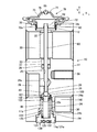
- FIG. 1 is a longitudinal sectional view showing a first embodiment of an expansion valve according to the present invention.
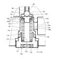
- FIG. 2 is a vertical cross-sectional view of the main part of the expansion valve of the first embodiment.
- FIG. 3 is a perspective view showing the vibration-proof spring of the first embodiment.
- FIG. 4 is a plan view showing the anti-vibration spring of the first embodiment.
- FIG. 5 is a side view showing the anti-vibration spring of the first embodiment.
- FIG. 6 is a plan view showing a vibration-proof spring of the second embodiment.
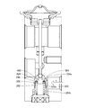
- FIG. 7 is a longitudinal sectional view showing an example of a conventional expansion valve.
- FIG. 8 is a diagram showing an example of the shape of the inlet channel of a conventional expansion valve.
- FIG. 9 is a diagram showing an example of the shape of the inlet channel of a conventional expansion valve.
- FIG. 10 is a diagram showing an example of the shape of the inlet channel of a conventional expansion valve.
- FIG. 1 is a longitudinal sectional view showing a first embodiment of an expansion valve according to the present invention.
- FIG. 2 is a vertical cross-sectional view of the main part of the expansion valve of the first embodiment.
- the expansion valve 10 includes a valve body 11, a power element 70, a valve body 40, a valve rod 60, an O-ring 36, a support member 100, a vibration isolation spring 140, a coil spring 44, and an adjustment screw 120. Yes.
- the valve body 11 is made of, for example, an aluminum alloy, and can be obtained, for example, by extruding an aluminum alloy or the like with the X direction in FIG.
- the valve body 11 includes a power element mounting portion 12 that is a female screw that is formed on an upper surface portion and is screwed into and fixed to a male screw 72a of the power element 70, an inlet port 20 into which a high-pressure refrigerant is introduced, and an inlet port.
- the power element mounting portion 12 is formed as a bottomed cylindrical hole having a circular opening on the upper surface of the valve body 11 and having an internal thread on the inner wall surface thereof. In the center of the bottom of the hole, an opening 32 that reaches (communicates with) the return passage 30 is formed.
- the direction of the central axis of the power element attachment portion 12 is a direction (Y direction) substantially orthogonal to the passage direction (X direction) of the refrigerant passing through the return passage 30.
- the female screw 11a is formed so as to open in the lower surface of the valve body 11, and an insertion hole 11b is formed in the upper part thereof.
- a valve chamber 24 is formed inside the valve body 11 by sealing the opening of the female screw 11 a with the adjusting screw 120.
- the valve chamber 24 has a cylindrical side wall surface, and an upper wall surface 24a is above the upper end of the inlet hole 20a, and a lower wall surface 24b is below the lower end of the inlet hole 20a.
- the upper wall surface 24a has a vertical length required for a vibration-proof spring 140 (described later) to slide.
- the part between the upper end of the insertion hole 11b and the inlet hole 20a should just have thickness required for intensity
- the inlet port 20 is formed to communicate with the valve chamber 24 from the side of the valve chamber 24 through an inlet hole 20a having a smaller diameter than the inlet port 20. Further, a narrowed portion 28 a having a diameter smaller than that of the outlet port 28 is provided at the back of the outlet port 28, and the narrowed portion 28 a is disposed above the valve chamber 24. The narrowed portion 28a communicates with the upper end portion of the valve chamber 24 through the valve hole 26 serving as an orifice.
- a valve seat 25 is formed on the valve chamber 24 side of the valve hole 26.
- a through hole 29 is formed in the valve body 11 in the vertical direction (Y direction in FIG. 1) so as to communicate the return passage 30 and the narrowed portion 28a.
- the valve hole 26, the through hole 29, the opening 32, and the valve chamber 24 are arranged so that their central axes are on the same straight line.
- the return passage 30 is formed further above the outlet port 28 in the valve body 11, and is formed so as to penetrate the valve body 11 in the lateral direction (X direction in FIG. 1).
- a hole 33 having a larger inner diameter than the through hole 29 is formed below the return passage 30 and is coaxial with the through hole 29.
- the inlet port 20 and the outlet port 28 open to the left and right of the valve body 11, and similarly the return passage 30 is formed so as to penetrate the left and right of the valve body 11.
- Both openings of the outlet port and the return passage can be variously changed depending on the layout of the refrigeration cycle in which the expansion valve is arranged.
- the left side opening of the outlet port 28 and the return passage 30 is opened to the front side or the back side of the paper in FIG. 1 (that is, the inlet port and the outlet port are orthogonal to each other when viewed from the center line of the valve rod 60).
- both openings of the return passage may be formed to be orthogonal to each other).
- the power element 70 includes, for example, an upper lid member 71 formed of stainless steel or the like, a receiving member 72 having a through-hole 72b in the center, a diaphragm 73 sandwiched between the upper lid member 71 and the receiving member 72, and the diaphragm. 73 and a stopper member 90 disposed between the receiving member 72 and the receiving member 72. And the end part which piled up the upper cover member 71, the diaphragm 73, and the receiving member 72 is circumferential-welded, and these are integrated.
- a pressure working chamber 75 is formed between the upper lid member 71 and the diaphragm 73. After the working gas is sealed in the pressure working chamber 75, the pressure working chamber 75 is sealed with a sealing plug 65.
- the lower portion of the receiving member 72 is cylindrical, and a male screw 72a is formed around it.
- a female screw of the power element mounting portion 12 a female screw opened on the upper surface of the valve body 11
- a power element 70 is attached to the valve body 11.
- the valve body 40 is a spherical member disposed so as to face the valve seat 25 and is provided in the valve chamber 24.
- the valve stem 60 is provided so as to be inserted into each of the valve hole 26, the through hole 29 and the opening 32 of the valve body 11, and the upper end of the valve stem 60 is below the stopper member 90 of the power element 70. It abuts on the provided receiving portion 92, and its lower end is arranged so as to contact the valve body 40.
- the O-ring 36 is attached to the hole 33, and a stopper member 37 attached to the upper part prevents the O-ring 36 from coming off.
- the support member 100 is a member that supports the valve body 40 in the direction of the valve seat 25 (the direction of the valve stem 60). Although the valve body 40 is fixed to the support member 100, the support member 100 is always biased in the direction of the valve seat 25 and the valve stem 60 by the coil spring 44, so that the support member 100 contacts the valve body 40. Only the structure may be sufficient.
- the support member 100 includes a main body portion 103, an upper surface portion 101, and a flange portion 102.
- the upper surface of the cylindrical main body 103 is an upper surface 101 that has a conical recess and supports the lower surface of the valve body 40.
- the support member 100 includes a flange portion 102 that protrudes from the main body portion 103 to the side surface (to the outer peripheral side), and the lower surface of the flange portion 102 is configured to receive one end of the vibration-proof spring 140 and the coil spring 44. .
- the outer diameter of the main body portion 103 below the flange portion 102 is configured to be smaller than the inner diameter of the coil spring 44 and enters the inside of the coil spring 44.
- the coil spring 44 is installed between the lower surface of the flange portion 102 provided in the support member 100 and the recess 125 formed in the adjustment screw 120.
- the valve body 40 is biased toward the valve seat 25 via the support member 100 by the elastic force of the coil spring 44.
- An anti-vibration spring 140 is installed between the lower surface of the flange portion 102 and the coil spring 44. Details of this configuration will be described later.
- the adjustment screw 120 includes a main body part 121, a hexagonal hole 122, an insertion part 123, a tip part 124, and a recess 125.
- the insertion portion 123 is provided on the upper portion of the main body portion 121 with an outer diameter smaller than that of the main body portion 121
- the distal end portion 124 is provided on the upper portion of the insertion portion 123 with an outer diameter smaller than that of the insertion portion 123.
- the outer periphery of the main body 121 is a male screw portion 121 a for screwing into a female screw 11 a that opens to the lower surface of the valve main body 11.
- a concave portion 125 having an open upper portion and having a cylindrical space is provided on the upper portion of the adjusting screw 120.
- the recess 125 is formed to a depth reaching the vicinity of the main body 121.
- the inner diameter of the recess 125 is slightly larger than the outer diameter of the coil spring 44 so that the coil spring 44 is stably disposed in the recess 125.
- a hexagon hole 122 for inserting a hexagon wrench (not shown) for turning the adjustment screw 120 is provided at the lower part of the adjustment screw 120 (main body 121).
- FIG. 3 is a perspective view showing the anti-vibration spring 140 of the first embodiment.
- FIG. 4 is a plan view showing the anti-vibration spring 140 of the first embodiment.
- FIG. 5 is a side view showing the anti-vibration spring of the first embodiment.
- the anti-vibration spring 140 includes a base portion 141 and a leg portion 142.
- the anti-vibration spring 140 can be press-formed from an elastic plate material such as stainless steel or an alloy thereof.
- the base 141 is an annular plate-like member that forms the upper part of the vibration-proof spring 140, and has a mounting hole 141a at the center.
- a plurality of leg portions 142 extend from the outer peripheral side of the base portion 141 in a direction perpendicular to the circumferential tangent, in other words, radially.
- the leg part 142 includes an upper part 142a, a bent part 142b, a side part 142c, and a protruding part 142d. Further, the leg portion 142 is bent downward at the bent portion 142b.
- the upper part 142a is formed in substantially the same plane as the base part 141. For this reason, a notch 145 having a predetermined shape is secured on the surface having the base portion 141 at the base portion of each leg portion 142.
- the length C is the length of the upper portion 142a. Since the leg portion 142 includes the upper portion 142a, the leg portion 142 is formed on the same side as the base portion 141 from the center side of the base portion 141 with respect to the bent portion.
- the notch 145 formed between the side surfaces in the width direction of the adjacent upper portions 142a has the same curvature from the root side surface of the upper portion 142a.
- the notch 145 may be formed in a shape other than the arc shape by connecting with a different curvature from the base side surface of the upper portion 142a.
- the bent portion 142b is formed to bend downward (coil spring 44 side) continuously from the upper portion 142a to the outside.
- the bent portion 142b may be accompanied by a certain curvature radius.
- the bent portion 142b is formed by bending (90- ⁇ ) degrees.
- the side portion 142c is formed in a straight line continuously below the bent portion 142b.
- the angle of the side portion 142c is ⁇ degrees toward the lower outer side with respect to the vertical direction.
- the protruding portion 142d is formed outward in the vicinity of the lower end of the side portion 142c.
- the protrusion 142d can be formed of a part of a spherical surface such as a hemisphere.
- the protrusion 142d When the protrusion 142d is mounted in the valve body 11, it elastically contacts the upper portion (upper wall surface 24a) of the opening of the inlet hole 20a, but even when the valve body 40 is at the lowest position.
- the dimensions of each part are set so that the protrusion 142d does not enter the opening of the inlet hole 20a.
- the length of the leg 142 in the vertical direction is set to an appropriate length at the lowest end within the range of vertical movement of the vibration-proof spring 140 unless the lower end of the leg 142 falls into the opening of the inlet hole 20a.
- the width of each leg portion 142 is such that all of the upper portion 142a, the bent portion 142b, and the side portion 142c are formed with a constant width.
- the width is limited to that.
- the width of the tip can be narrowed or conversely widened, or the shape can be changed to the most suitable shape for suppressing the vibration of the valve body.
- the thickness of the leg portion 142 (when the anti-vibration spring 140 is formed by pressing from one elastic plate material, the thickness of the anti-vibration spring 140) is also set to a thickness suitable for suppressing vibration of the valve body. .
- the anti-vibration spring 140 has a gap D (FIG. 4) for allowing the refrigerant to pass between adjacent leg portions 142. Further, the outer diameter of the anti-vibration spring 140 connected at the tip of the projecting portion 142d is larger than the inner diameter of the upper wall surface 24a in the valve chamber 24. The protrusion 142d presses against the wall surface 24a. In addition, a size is ensured in which the coil spring 44 is disposed inside the leg portion 142.
- the base portion 141 of the anti-vibration spring 140 is passed through the body portion 103 of the support member 100 from the lower side through the mounting hole 141 a of the anti-vibration spring 140. Is brought into contact with the lower surface of the flange portion 102 of the support member 100.
- the coil spring 44 is attached from the lower side of the vibration-proof spring 140.
- the main body 103 of the support member 100 is disposed inside the coil spring 44, and the upper surface of the coil spring 44 abuts on the lower surface of the base 141 of the vibration isolation spring 140.
- the vibration-proof spring 140 is installed in the valve chamber 24.
- the high-pressure refrigerant discharged from the compressor flows from the inlet port 20 into the valve chamber 24 through the inlet hole 20a, and the valve hole 26.
- the outlet port 28 and delivered from an outlet port 28 to an evaporator (not shown).
- the refrigerant sent out from the evaporator passes through the return passage 30 so as to enter from the left inlet and to the right outlet, and returns to the compressor. At this time, a part of the refrigerant passing through the return passage 30 flows into the lower portion of the power element 70 from the opening 32.
- the pressure of the working gas in the pressure working chamber 75 is changed according to the temperature change of the refrigerant flowing into the lower part of the power element 70.
- the stopper member 90 moves up and down in response to the movement of the diaphragm 73 deformed according to the fluctuation of the internal pressure in the pressure working chamber 75.
- the movement of the stopper member 90 is transmitted to the valve body 40 via the valve rod 60, and the flow rate of the expanded refrigerant is controlled.
- the vibration isolation spring 140 behaves together with the valve body 40 and the support member 100.
- the vibration-proof spring 140 presses the upper wall surface 24a of the valve chamber 24 of the valve body 11 with a predetermined force
- the vibration-proof spring 140 slides, the protrusion 142d of the leg 242 and the valve chamber A frictional force is generated between the upper wall surfaces 24a of 24.
- the valve body 40 and the support member 100 do not react sensitively in the vertical direction to pressure fluctuations of the high-pressure refrigerant from the inlet port 20, and vibrations in the vertical direction can be prevented or reduced.
- the valve body 40 and the support are supported against pressure fluctuations of the high-pressure refrigerant from the inlet port 20.
- the member 100 does not easily move in the lateral direction against the pressing force, and exhibits the effect of preventing lateral vibration. At the same time, the vertical movement of the valve body 40 and the support member 100 is guided.
- the leg portion 142 is not applied to the inlet hole 20a, and the generation of refrigerant flow rate and turbulent flow is suppressed.
- the passage sound of the refrigerant can be reduced.
- the anti-vibration spring 140 is comprised by the leg part 142 extended radially, it can be easily attached in the valve main body 11 only by inserting from the opening part of the internal thread 11a formed in the bottom part of the valve main body 11. Can do.
- the anti-vibration spring 140 has a certain notch depth (notch 145) on the surface having the base 141, the length of the leg 142 can be made longer than the height of the anti-vibration spring. For this reason, the spring constant of the leg part 142 can be made small, the change of the force with respect to the deformation of the leg part 142 can be made small, and more stable sliding resistance can be obtained. Further, by making the widths of the leg portions 142 the same, it becomes easy to calculate the spring constant, that is, to design the first vibration isolation spring 140.
- leg 142 is formed in a direction perpendicular to the circumferential tangent of the base 141 (radially), thereby generating a sliding resistance without applying a twisting force in the circumferential direction of the base 141. Can do.
- FIG. 6 is a plan view showing a vibration-proof spring of the second embodiment.
- the anti-vibration spring 140 of the first embodiment is replaced with the anti-vibration spring 240, and the other parts are the same as those shown in the first embodiment. The explanation is omitted.
- the anti-vibration spring 240 includes a base portion 241 and a leg portion 242.
- the anti-vibration spring 240 can be press-formed from an elastic plate material such as stainless steel or an alloy thereof.
- the base 241 is an annular plate-like member that forms the upper part of the vibration-proof spring 240, and has a mounting hole 141a similar to that of the first embodiment.
- a plurality of the leg portions 242 extend from the outer peripheral side of the base portion 241 in a direction perpendicular to the circumferential tangent line, that is, radially. In the second embodiment, eight leg portions 242 are provided at equal angular intervals.
- the leg portion 242 includes an upper portion 242a, a bent portion 142b, a side portion 142c, and a protruding portion 142d.
- the bent portion 142b, the side portion 142c, and the protruding portion 142d are the same as those in the first embodiment.
- the first embodiment has the arc-shaped notch 145, but the second embodiment is different in that it has a substantially triangular notch 245.
- the length E of the upper part 242a of the second embodiment is longer than the length C of the upper part 142a of the first embodiment.
- the length of the leg portion 242 of the second embodiment is increased accordingly.
- the outer periphery of the base portion 241 of the second embodiment is smaller than the outer periphery of the base portion 141 of the first embodiment.
- the side surfaces in the width direction of the adjacent upper portions 242a may form small arc-shaped portions in consideration of strength and stress concentration.
- the length of the anti-vibration spring 240 can be further increased by forming the substantially triangular notch 245. For this reason, the spring constant of the leg part 242 can be made smaller, the change in force with respect to the deformation of the leg part 242 can be made smaller, and a more stable sliding resistance can be achieved.
- the present invention is not limited to the above-described examples, and includes various modifications.
- the invention is not limited to the one having all the configurations (structures) provided in the above-described embodiments. It is also possible to delete a part of the configuration of a certain embodiment, replace it with the configuration of another embodiment, or add the configuration of another embodiment to the configuration of a certain embodiment.
- the legs 142 and 242 indicate that the eight legs 142 having the same length are provided at equal angular intervals. If the number of the leg portions 142 and 242 is 8, stability of the behavior and sliding resistance can be ensured, and the balance of the gap between the leg portions can be maintained, but this is not restrictive. For example, two or more legs are sufficient, and the length is not limited to the same length and equiangular intervals. Moreover, even if the width of the leg part shown in the said Example changes in the middle, it is possible to employ
- the power element 70 shown in the above embodiment shows attachment by screws, but in addition to this, a cylindrical portion formed on the upper part of the valve body is provided, and the power element 70 is inserted inside the cylindrical portion.
- the power element 70 may be attached by caulking the cylindrical portion.
Landscapes
- Engineering & Computer Science (AREA)
- Physics & Mathematics (AREA)
- Mechanical Engineering (AREA)
- Thermal Sciences (AREA)
- General Engineering & Computer Science (AREA)
- Fluid Mechanics (AREA)
- Temperature-Responsive Valves (AREA)
Abstract
冷媒を弁室に流入する入口孔及び、前記冷媒を前記弁室から流出する弁孔を有する弁本体と、前記弁孔を流れる冷媒の量を調節する弁体と、前記弁本体に取り付けられて弁棒を介して前記弁体を駆動するパワーエレメントと、前記弁体を支持する支持部材と、前記支持部材を介して前記弁体を閉弁方向に押圧するコイルバネと、前記弁体の振動を防止する防振ばねと、を備え、前記防振ばねは、前記支持部材と前記コイルバネとの間に配置される円環状の基部と、前記基部から放射状に延びる複数の脚部と、を有し、前記脚部は前記コイルバネ側に折れ曲がり、前記弁室の側壁面における前記入口孔よりも前記弁孔側に接する膨張弁。
Description
本発明は、冷凍サイクルに用いられる感温機構内蔵型の膨張弁に関する。
従来、自動車に搭載される空調装置等に用いる冷凍サイクルについては、冷媒の通過量を温度に応じて調整する感温機構内蔵型の温度膨張弁が使用されている。このような膨張弁の弁本体は、高圧の冷媒が導入される入口ポートと入口ポートに連通する弁室とを有するとともに、弁本体の頂部には、パワーエレメントと称する弁体の駆動機構が装備される。
弁室内に配設される球状の弁体は、弁室に開口する弁孔の弁座に対向し配置される。弁体は、弁室内に配置された支持部材に支持され、弁本体に取り付けられた調整ねじと支持部材との間に設置されたコイルバネにより弁座方向へ付勢される。そして、弁体は、パワーエレメントにより駆動される弁棒により操作されて、弁座との間の絞り通路の開度を制御する。また、弁孔を通った冷媒は、出口ポートから蒸発器側へ送られる。
ここで、入口ポートから流れてきた高圧冷媒は、弁室を通過するが、膨張弁に送り込まれる高圧冷媒には、冷凍サイクル内において上流側で圧力変動が発生する場合があり、その圧力変動が伝達されると、弁体の動作を不安定にするという問題を生じる場合がある。この圧力変動が弁体の振動の原因となり、異音を発生することとなった。
このような振動を防止するため、従来、弁室内に弁体を弾性的に支持する防振ばねを設ける構成が提案されている(特許文献1~2参照)。
従来の防振ばねの構造は一定の防振効果を有するものの、以下のような問題点もあった。
すなわち、特許文献1には、弁体を支持する支持部材に、複数の弾性腕(脚部)を有する防振ばねを設け、この各脚部の先端を弁室内壁に弾性的に当接させることにより、支持部材をその周囲から中心に方向に向かって安定的に支持する構成が開示されている。
しかし、特許文献1においては防振ばねの脚部が入口ポートより弁室内に流入する冷媒に直接衝突する構成であるために、弁室内に導入される高圧冷媒に乱流発生の懸念が生じた。この点について、図7~10を用いて説明する。
しかし、特許文献1においては防振ばねの脚部が入口ポートより弁室内に流入する冷媒に直接衝突する構成であるために、弁室内に導入される高圧冷媒に乱流発生の懸念が生じた。この点について、図7~10を用いて説明する。
図7に示すように、圧縮機(図示せず)により送出される高圧冷媒は、矢印Aで示されるように入口ポート320に入り、入口孔320aを通って、弁室324へ導入される。ここで、従来の防振ばね300は、弁体の支持部材400及び該支持部材400を弁体側に付勢するコイルばね344の間に挟持される円環状の板状部301と、該板状部301から放射状にかつ弁棒の中心軸方向に傾斜して折曲形成された複数の脚部302とより成る。そして、この複数の脚部302が入口孔320aより下側の弁室324の下側壁324bまで延びている。ここで、防振ばね300を取り付ける際の角度(防振ばね300の中心点を中心とした回転角度)に応じて、入口孔320aに対して、脚部302が様々な流路形状を形成することになる。
図8~10は、入口ポート320側から見た入口孔320aと脚部302による入口流路の形状例を示す。図8は、脚部302が入口孔320aの中央で上下方向に位置し、対面流路が2股に別れた場合を示している。図9は、脚部302が入口孔320aの片側を塞いでいる場合を示している。図10は、脚部302が入口孔320aの両側に位置し、門型流路となる場合を示している。このように様々な態様で脚部302が入口孔320aの一部を塞ぎ、入口流路もそれに応じた形状となるため、防振ばね300の向きによっては乱流が生じる可能性がある。乱流により、冷媒通過音が発生し、泡混じりの気泡が破裂すること等による異音の発生が懸念される。また、導入される冷媒の流量が低下する懸念もある。
これに対し、特許文献2は、防振ばねの脚部を弁棒の中心軸を中心として半径方向に湾脚させることにより、脚部の前記中心軸方向の長さを短くする技術を開示しているが、この場合、防振ばねを捻じりながら弁本体内に挿入しないと、脚部の特に根元の部分に負荷がかかり、防振ばねの変形を招いたりする懸念もあった。
これに対し、特許文献2は、防振ばねの脚部を弁棒の中心軸を中心として半径方向に湾脚させることにより、脚部の前記中心軸方向の長さを短くする技術を開示しているが、この場合、防振ばねを捻じりながら弁本体内に挿入しないと、脚部の特に根元の部分に負荷がかかり、防振ばねの変形を招いたりする懸念もあった。
そこで、本発明の目的は、弁体の振動を抑制し、かつ、防振ばねの変形を抑えて冷媒の通過音を低減させた防振ばねを備える膨張弁を提供することにある。
上記課題を解決するために、代表的な本発明の膨張弁の1つは、冷媒を弁室に流入する入口孔及び、前記冷媒を前記弁室から流出する弁孔を有する弁本体と、前記弁孔を流れる冷媒の量を調節する弁体と、前記弁本体に取り付けられて弁棒を介して前記弁体を駆動するパワーエレメントと、前記弁体を支持する支持部材と、前記支持部材を介して前記弁体を閉弁方向に押圧するコイルバネと、前記弁体の振動を防止する防振ばねと、を備え、前記防振ばねは、前記支持部材と前記コイルバネとの間に配置される円環状の基部と、前記基部から放射状に延びる複数の脚部と、を有し、前記脚部は前記コイルバネ側に折れ曲がり、前記弁室の側壁面における前記入口孔よりも前記弁孔側に接する。
本発明による膨張弁の一実施例において、前記複数の脚部は、前記基部と同一面において隣接する脚部同士の接続部を有していてもよい。
この発明による膨張弁は、上記のように構成されているので、弁体の振動を抑制し、かつ、防振ばねの変形を抑えて冷媒の通過音を低減させることができる。
<第1実施例>
図1は、本発明による膨張弁の第1実施例を示す縦断面図である。図2は、第1実施例の膨張弁の要部の縦断面図である。
図1は、本発明による膨張弁の第1実施例を示す縦断面図である。図2は、第1実施例の膨張弁の要部の縦断面図である。
図1に示すように、膨張弁10は、弁本体11、パワーエレメント70、弁体40、弁棒60、Oリング36、支持部材100、防振ばね140、コイルバネ44、調整ねじ120を備えている。
弁本体11は、例えばアルミ合金製であって、例えば図1のX方向を押出方向として、アルミ合金等を押出成形し、これに機械加工を施すことによって得ることができる。この弁本体11は、上面部に形成されパワーエレメント70の雄ねじ72aに螺合してこれを固定する雌ねじであるパワーエレメント取付部12と、高圧の冷媒が導入される入口ポート20と、入口ポート20より流入した冷媒が流出する冷媒の出口ポート28と、冷媒の戻り通路30と、Oリング36を取り付ける穴部33と、弁本体11の底面部に形成された雌ねじ11aと、弁本体11を図示されない蒸発器や他の部品等に取り付けるための取付穴(あるいは取付用雌ねじ)80等とを有する。
パワーエレメント取付部12は、弁本体11の上面に円形状に開口し、その内壁面に雌ねじを有する有底の円筒状穴として形成される。この穴の底部中央には戻り通路30に至る(連通する)開口32が形成されている。ここで、パワーエレメント取付部12の中心軸の方向は、戻り通路30内を通過する冷媒の通過方向(X方向)とほぼ直交する方向(Y方向)となっている。
雌ねじ11aは、弁本体11の下面に開口するように形成されており、その上部に挿入穴11bが形成されている。雌ねじ11aの開口部分を調整ねじ120で封鎖することにより弁本体11の内部に弁室24が形成される。弁室24は、円筒状の側壁面を備え、入口孔20aの上端より上方が上壁面24a、入口孔20aの下端より下方が下壁面24bである。上壁面24aは後述する防振ばね140が摺動するのに必要な上下方向の長さが確保されている。また、挿入穴11bの上端と入口孔20aの間の部分は、強度に必要な厚みを有していればよい。
入口ポート20は、弁室24の側方から入口ポート20より小径の入口孔20aを介して弁室24と連通して形成されている。また、出口ポート28の奥には出口ポート28よりも小径の狭窄部28aが設けられており、この狭窄部28aは、弁室24の上方に配置されている。この狭窄部28aは、オリフィスとなる弁孔26を介して弁室24の上端部に連通している。また、弁孔26の弁室24側には、弁座25が形成されている。弁本体11には戻り通路30と狭窄部28aとを連通するように上下方向(図1におけるY方向)に通し孔29が形成されている。そして、弁孔26と通し孔29と開口32と弁室24とは、それぞれの中心軸が同一直線上になるように配置されている。戻り通路30は、弁本体11における出口ポート28のさらに上方に形成され、弁本体11を横方向(図1におけるX方向)に貫通するように形成されている。また、戻り通路30の下側に、通し孔29と同軸で通し孔29よりも内径の大きい穴部33が形成されている。
なお、図1においては、入口ポート20及び出口ポート28は弁本体11の左右に開口し、同様に戻り通路30も弁本体11の左右を貫通するように形成されているが、これら入口ポート、出口ポート及び戻り通路の両開口は、当該膨張弁が配置される冷凍サイクルのレイアウトによって種々変更が可能である。例えば出口ポート28及び戻り通路30の左側開口は、図1の紙面手前側あるいは紙面奥側に開口するように(すなわち弁棒60の中心線から見た場合に入口ポート及び出口ポートが直交するように、同様に戻り通路の両開口も直交するように形成)しても良い。
パワーエレメント70は、例えばステンレス鋼等で形成された上蓋部材71及び中央部に貫通口72bを備えた受け部材72と、これら上蓋部材71及び受け部材72の間に挟み込まれるダイアフラム73と、このダイアフラム73及び受け部材72の間に配置されたストッパ部材90等から構成されている。そして、上蓋部材71、ダイアフラム73及び受け部材72を重ね合わせた端部を周溶接することにより、これらは一体化されている。上蓋部材71とダイアフラム73との間には、圧力作動室75が形成され、この圧力作動室75内に作動ガスが封入された後、封止栓65で封止される。受け部材72の下部は円筒状でその周囲には雄ねじ72aが形成され、パッキン35を介してパワーエレメント取付部12の雌ねじ(弁本体11の上面に開口された雌ねじ)と螺合することにより、パワーエレメント70が弁本体11に取付けられている。
弁体40は、弁座25に対向するように配置された球状の部材であり、弁室24内に設けられている。弁棒60は、弁本体11の弁孔26、通し孔29及び開口32のそれぞれに挿通される態様で設けられており、弁棒60の上端は、パワーエレメント70のストッパ部材90の下側に設けられた受け部92に当接し、その下端は、弁体40と接触するように配置される。Oリング36は、穴部33に装着されており、上部に装着される止め部材37がOリング36の抜け止めとなっている。
支持部材100は、弁体40を弁座25の方向(弁棒60の方向)に支持する部材である。弁体40は支持部材100に固着されているが、支持部材100は常にコイルばね44により弁座25及び弁棒60の方向に付勢されているので、支持部材100が弁体40に当接するだけの構成でもよい。支持部材100は、本体部103、上面部101、フランジ部102を備えている。円柱状の本体部103の上面は円錐状のくぼみを備えて弁体40の下面を支持する上面部101となっている。また、支持部材100は本体部103より側面(外周側に)に突出するフランジ部102を備えており、当該フランジ部102の下面が防振ばね140及びコイルバネ44の一端を受ける構造となっている。このときフランジ部102より下側の本体部103の外径はコイルバネ44の内径よりも小さく構成され、コイルバネ44の内側に入るようになっている。
コイルバネ44は、支持部材100に設けられたフランジ部102の下面と調整ねじ120に形成された凹部125との間に設置されている。このコイルバネ44の弾性力により、弁体40は支持部材100を介して弁座25に向けて付勢されている。フランジ部102の下面とコイルバネ44の間には、防振ばね140が設置されるがこの構成の詳細は後述する。
調整ねじ120は、本体部121、六角穴122、挿入部123、先端部124、凹部125を備えている。挿入部123は本体部121の上部に本体部121よりも外径が縮径して設けられ、先端部124は挿入部123の上部に挿入部123よりも外径が縮径して設けられている。また、本体部121の外周は弁本体11の下面に開口する雌ねじ11aに螺合するための雄ねじ部121aとなっている。さらに、調整ねじ120の上部には、上部が開口して円柱状の空間を有する凹部125が設けられている。凹部125は本体部121近辺まで達する深さに形成されている。また、凹部125の内径は、コイルバネ44が凹部125内に安定的に配置されるようにコイルバネ44の外径よりやや大きい内径となっている。また、調整ねじ120(本体部121)の下部には、該調整ねじ120を回すための図示されない六角レンチ挿入用の六角穴122が設けられている。
図3は、第1実施例の防振ばね140を示す斜視図である。図4は、第1実施例の防振ばね140を示す平面図である。図5は、第1実施例の防振ばねを示す側面図である。防振ばね140は、基部141と脚部142を備えている。防振ばね140は、ステンレス鋼、その合金等、弾性のある板材からプレス成形することができる。
基部141は、防振ばね140の上部を形成する円環状の板状の部材であり、中央に取付孔141aを有する。
脚部142は、基部141の外周側から周方向の接線に対して垂直方向に、換言すれば放射状に、複数延びている。第1実施例では同じ長さの8本の脚部142が等角度間隔で備えられている。脚部142は、上部142a、折り曲がり部142b、側部142c、突起部142dで構成されている。また、脚部142は、折り曲がり部142bにおいて下方に折り曲げられている。
上部142aは、基部141と略同一平面で形成されている。このため、各脚部142の根元の部分においては基部141を有する面において、それぞれ所定形状の切欠145を確保している。図4では長さCが上部142aの長さとなる。脚部142が上部142aを備えることで、基部141と同一面において脚部142は折り曲がり部よりも基部141の中心側から形成されていることになる。また、上部142aの基部141への接続部の付近(脚部142の付け根付近)において、隣り合う上部142aの幅方向の側面の間に形成された切欠145は、上部142aの根本側面から同じ曲率で連続して結ぶことで円弧状に形成されており、これにより上部142a同士(脚部142同士)が滑らかに接続されている。もちろん、切欠145は、上部142aの根本側面から異なる曲率で結ぶことで円弧状以外の形状にて形成されても良い。
折り曲がり部142bは、上部142aから外側に連続して下方(コイルバネ44側)に向けて折り曲がり形成されている。折り曲がり部142bは、一定の曲率半径を伴っていてもよい。折り曲がり部142bは、(90-θ)度曲げ加工して形成される。
側部142cは、折り曲がり部142bの下方に連続して直線状に形成されている。側部142cの角度は、上下方向に対して下方外側に向けてθ度を有している。
突起部142dは、側部142c下端近傍に外側に向けて形成されている。例えば、突起部142dは半球状など、球表面の一部等により形成できる。この突起部142dは、弁本体11内に装着されると入口孔20aの開口部上部の部分(上壁面24a)に弾発的に接触するが、弁体40が最下限位置となった場合でも突起部142dが入口孔20aの開口部に入り込まないように、各部の寸法が設定されている。
脚部142の上下方向の長さは、防振ばね140の上下移動の範囲内における最下端において、脚部142の下端部が入口孔20aの開口部内に落ちなければ適宜の長さで設定されることができるが、入口ポート20から導入される冷媒の流れを阻害しないためには、脚部142の下端部が入口孔20aの開口部に達しないようにすることが望ましい。また、本実施例においてはそれぞれの脚部142の幅は上部142a、折り曲がり部142b、側部142cのいずれも一定の幅で形成されているが、本発明においては特にそれのみに限定されることはなく、先端の幅を狭くしたり、逆に広くしたり、その他、弁体の振動抑制に最も相応しい形状に変更が可能である。また、脚部142の厚み(防振ばね140を1枚の弾性板材よりプレス加工して形成する場合には、防振ばね140の厚み)も弁体の振動抑制に相応しい厚さが採用される。
防振ばね140においては、隣り合う脚部142の間には冷媒が通過するための隙間D(図4)を有している。また、防振ばね140における突起部142d先端部で結ばれる外径は、弁室24内の上壁面24aの内径よりも大きくなっており、取り付けた際に弾性力が働き、弁室24の上壁面24aへ突起部142dが押圧するようになっている。また、脚部142の内側にコイルバネ44が配置される大きさが確保されている。
図1、2に示されるように、防振ばね140の装着に際しては、まず支持部材100の本体部103に、下側から防振ばね140の取付孔141aに通し、防振ばね140の基部141の上面を支持部材100のフランジ部102の下面に当接させる。次に、防振ばね140の下側からコイルバネ44を取り付ける。このとき、コイルバネ44の内側に支持部材100の本体部103が配置され、コイルバネ44の上面が防振ばね140の基部141下面に当接する。これにより、防振ばね140は、弁室24内に設置される。
防振ばね140を取り付けた膨張弁10において、防振ばね140の基部141は下側からコイルバネ44により付勢されているため、支持部材100のフランジ部102とコイルバネ44の間に所定の力で挟持されることにより取り付けられていることとなる。そして、防振ばね140は、脚部142の弾性力により突起部142dが弁室24の上壁面24aへ向けて所定の力で押され、弁体40の動きに応じて、摺動抵抗が発生する。
次に、作用について説明する。本発明の第1実施例の膨張弁10においては、圧縮機(図示せず)から吐出された高圧の冷媒は入口ポート20から入口孔20aを通って弁室24内に流入し、弁孔26を通過して膨張され、出口ポート28から蒸発器(図示せず)へ送り出される。また、この蒸発器から送り出された冷媒は、戻り通路30の左側入口から入って右側出口に抜けるように通過し、圧縮機へ戻る。このとき、戻り通路30内を通過する冷媒の一部は開口32からパワーエレメント70の下部に流入する。そしてパワーエレメント70の下部に流入した冷媒の温度変化に応じて圧力作動室75内の作動ガスの圧力を変化させる。このとき、圧力作動室75における内圧の変動に応じて変形したダイアフラム73の動きを受け、ストッパ部材90が上下動する。そして、ストッパ部材90の移動が弁棒60を介して弁体40に伝達され、膨張される冷媒の流量が制御される。
弁体40が開閉方向(上下方向)へ動く場合、防振ばね140は、弁体40及び支持部材100と共に挙動する。このとき、防振ばね140は所定の力で弁本体11の弁室24の上壁面24aを押圧しているため、防振ばね140が摺動する際、脚部242の突起部142dと弁室24の上壁面24aの間で摩擦力が発生する。これにより、入口ポート20からの高圧冷媒の圧力変動に対して弁体40及び支持部材100が上下方向に敏感に反応することがなくなり、上下方向の振動を防止又は低減することができる。さらに、防振ばね140から弁室24の上壁面24aへ複数の脚部142により複数の箇所で押圧しているため、入口ポート20からの高圧冷媒の圧力変動に対して、弁体40及び支持部材100が押圧力に抗して横方向に簡単に動くことがなく、横方向の振動を防止する効果を発揮する。同時に、弁体40及び支持部材100の上下方向の動きをガイドする。
また、防振ばね140は、弁室24における入口孔20aより上の上壁面24aで接しているため、脚部142が、入口孔20aにかかることがなく、冷媒流量や乱流の発生を抑制し冷媒の通過音を低減させることができる。また、防振ばね140は、放射状に延びた脚部142で構成されているため、弁本体11の底部に形成された雌ねじ11aの開口部から挿入するだけで容易に弁本体11内への取付ができる。さらに、防振ばね140は、基部141を有する面において一定の切欠深さ(切欠145)を有していることから、脚部142の長さを防振ばねの高さ以上に長くできる。このため、脚部142のバネ定数を小さくでき、脚部142の変形に対する力の変化を小さくでき、より安定した摺動抵抗を得ることができる。また、脚部142の幅を同じにすることで、バネ定数の計算、すなわち当該第1防振ばね140の設計がし易くなる。また、脚部142が基部141の周方向の接線に対して垂直方向に(放射状に)形成されることで、基部141の円周方向のねじりの力をかけずに摺動抵抗を発生させることができる。
<第2実施例>
図6は、第2実施例の防振ばねを示す平面図である。第2実施例は、第1実施例の防振ばね140を防振ばね240に置き換えた構成であり、それ以外は第1実施例で示したものと共通であるので、共通の箇所は再度の説明を省略してある。
図6は、第2実施例の防振ばねを示す平面図である。第2実施例は、第1実施例の防振ばね140を防振ばね240に置き換えた構成であり、それ以外は第1実施例で示したものと共通であるので、共通の箇所は再度の説明を省略してある。
防振ばね240は、基部241と脚部242を備えている。防振ばね240は、ステンレス鋼、その合金等、弾性のある板材からプレス成形することができる。
基部241は、防振ばね240の上部を形成する円環状の板状の部材であり、中央に第1実施例と同様の取付孔141aを有する。
脚部242は、基部241の外周側から周方向の接線に対して垂直方向に、すなわち放射状に複数延びている。第2実施例では8本の脚部242が等角度間隔で備えられている。脚部242は、上部242a、折り曲がり部142b、側部142c、突起部142dで構成され、折り曲がり部142b、側部142c、突起部142dは第1実施例と同様である。
ここで、第1実施例では円弧状の切欠145を有していたが、第2実施例では略三角状の切欠245となっている点で異なる。このため、第2実施例の上部242aの長さEは、第1実施例の上部142aの長さCよりも長い。そして、その分だけ第2実施例の脚部242の長さは、長くなる。また、第2実施例の基部241の外周は第1実施例の基部141の外周よりも小さくなっている。なお、隣り合う上部242aの幅方向の側面は、強度や応力集中を考慮して小さい円弧状部を形成してもよい。
第2実施例では、略三角状の切欠245を形成することで、防振ばね240の長さをさらに長くできる。このため、脚部242のバネ定数をより小さくでき、脚部242の変形に対する力の変化をより小さくでき、より安定した摺動抵抗とすることができる。
以上の様に、本発明の実施形態について第1実施例、第2実施例を示してきたが、本発明は上記した実施例に限定されるものではなく、様々な変形例が含まれる。例えば、上記した実施例に設けられた全ての構成(構造)を備えるものに限定されるものではない。また、ある実施例の構成の一部を削除したり、他の実施例の構成に置き換えたり、あるいはまた、ある実施例の構成に他の実施例の構成を加えることも可能である。
例えば、上記実施例では、脚部142、242は、同じ長さの8本の脚部142が等角度間隔で備えていることを示した。脚部142、242の本数が8本であれば挙動の安定性と摺動抵抗を確保でき、脚部間の隙間のバランスも保たれるが、これに限られるものではない。例えば、脚部は2本以上であれば、良く、また、同じ長さ、等角度間隔に限らなくても良い。また、上記実施例で示した脚部の幅が途中で変わるものであっても採用することは可能である。
また、上記実施例で示したパワーエレメント70は、ねじによる取り付けを示しているが、これ以外に、弁本体上部に形成された円筒部を設け、この円筒部の内側にパワーエレメント70を挿入し、該円筒部を内側カシメ加工することにより、該パワーエレメント70を取り付ける構成でも良い。
10 膨張弁
11 弁本体
20 入口ポート
20a 入口孔
24 弁室
24a 上壁面
25 弁座
26 弁孔
28 出口ポート
30 戻り通路
40 弁体
44 コイルバネ
60 弁棒
70 パワーエレメント
100 支持部材
120 調整ねじ
140、240 防振ばね
141、241 基部
142、242 脚部
11 弁本体
20 入口ポート
20a 入口孔
24 弁室
24a 上壁面
25 弁座
26 弁孔
28 出口ポート
30 戻り通路
40 弁体
44 コイルバネ
60 弁棒
70 パワーエレメント
100 支持部材
120 調整ねじ
140、240 防振ばね
141、241 基部
142、242 脚部
Claims (2)
- 冷媒を弁室に流入する入口孔及び、前記冷媒を前記弁室から流出する弁孔を有する弁本体と、
前記弁孔を流れる冷媒の量を調節する弁体と、
前記弁本体に取り付けられて弁棒を介して前記弁体を駆動するパワーエレメントと、
前記弁体を支持する支持部材と、
前記支持部材を介して前記弁体を閉弁方向に押圧するコイルバネと、
前記弁体の振動を防止する防振ばねと、を備え、
前記防振ばねは、前記支持部材と前記コイルバネとの間に配置される円環状の基部と、前記基部から放射状に延びる複数の脚部と、を有し、
前記脚部は前記コイルバネ側に折れ曲がり、前記弁室の側壁面における前記入口孔よりも前記弁孔側に接する膨張弁。 - 前記複数の脚部は、前記基部と同一面において隣接する脚部同士の接続部を有する、
請求項1に記載の膨張弁。
Priority Applications (4)
| Application Number | Priority Date | Filing Date | Title |
|---|---|---|---|
| US16/322,961 US20190178542A1 (en) | 2016-08-09 | 2017-07-21 | Expansion valve |
| CN202310468583.XA CN116336703A (zh) | 2016-08-09 | 2017-07-21 | 膨胀阀 |
| EP17839188.4A EP3499150A4 (en) | 2016-08-09 | 2017-07-21 | REGULATOR |
| CN201780048788.5A CN109564042A (zh) | 2016-08-09 | 2017-07-21 | 膨胀阀 |
Applications Claiming Priority (2)
| Application Number | Priority Date | Filing Date | Title |
|---|---|---|---|
| JP2016156352A JP6697975B2 (ja) | 2016-08-09 | 2016-08-09 | 膨張弁 |
| JP2016-156352 | 2016-08-09 |
Publications (1)
| Publication Number | Publication Date |
|---|---|
| WO2018030115A1 true WO2018030115A1 (ja) | 2018-02-15 |
Family
ID=61161965
Family Applications (1)
| Application Number | Title | Priority Date | Filing Date |
|---|---|---|---|
| PCT/JP2017/026432 WO2018030115A1 (ja) | 2016-08-09 | 2017-07-21 | 膨張弁 |
Country Status (5)
| Country | Link |
|---|---|
| US (1) | US20190178542A1 (ja) |
| EP (1) | EP3499150A4 (ja) |
| JP (1) | JP6697975B2 (ja) |
| CN (2) | CN116336703A (ja) |
| WO (1) | WO2018030115A1 (ja) |
Families Citing this family (2)
| Publication number | Priority date | Publication date | Assignee | Title |
|---|---|---|---|---|
| JP7015769B2 (ja) * | 2018-10-12 | 2022-02-03 | 株式会社鷺宮製作所 | 温度式膨張弁、および、それを備える冷凍サイクルシステム |
| CN113623901A (zh) * | 2020-05-09 | 2021-11-09 | 盾安环境技术有限公司 | 节流装置及空调系统 |
Citations (6)
| Publication number | Priority date | Publication date | Assignee | Title |
|---|---|---|---|---|
| JP2001012824A (ja) * | 1999-04-27 | 2001-01-19 | Denso Corp | 制御弁 |
| JP2001082835A (ja) * | 1999-09-13 | 2001-03-30 | Denso Corp | 圧力制御弁 |
| JP2003090648A (ja) * | 2001-09-17 | 2003-03-28 | Tgk Co Ltd | 膨張弁 |
| JP2005156046A (ja) | 2003-11-27 | 2005-06-16 | Fuji Koki Corp | 膨張弁 |
| JP2013068368A (ja) | 2011-09-22 | 2013-04-18 | Fuji Koki Corp | 弁装置 |
| WO2016199610A1 (ja) * | 2015-06-09 | 2016-12-15 | 株式会社デンソー | 減圧弁 |
Family Cites Families (15)
| Publication number | Priority date | Publication date | Assignee | Title |
|---|---|---|---|---|
| JPS60253773A (ja) * | 1984-05-31 | 1985-12-14 | カルソニックカンセイ株式会社 | 膨張弁 |
| JP4078519B2 (ja) * | 2001-12-26 | 2008-04-23 | Nok株式会社 | 圧力開放弁 |
| KR100463057B1 (ko) * | 2002-11-08 | 2004-12-23 | 현대자동차주식회사 | 에어컨 냉매의 유동 소음 저감장치 |
| JP4255892B2 (ja) * | 2003-11-06 | 2009-04-15 | 株式会社不二工機 | 膨張弁 |
| KR20070062318A (ko) * | 2005-12-12 | 2007-06-15 | 기아자동차주식회사 | 자동차용 에어컨 팽창밸브 |
| CN101118020A (zh) * | 2006-08-01 | 2008-02-06 | 王永乐 | 热力膨胀阀 |
| CN102588669B (zh) * | 2011-01-07 | 2015-07-01 | 浙江三花汽车零部件有限公司 | 热力膨胀阀 |
| JP5906371B2 (ja) * | 2012-01-11 | 2016-04-20 | 株式会社テージーケー | 膨張弁および防振ばね |
| CN202630539U (zh) * | 2012-05-31 | 2012-12-26 | 宁波松鹰汽车部件有限公司 | 一种减振消噪的热力膨胀阀 |
| JP6143500B2 (ja) * | 2013-03-08 | 2017-06-07 | 株式会社不二工機 | 温度式膨張弁 |
| JP6142181B2 (ja) * | 2013-03-12 | 2017-06-07 | 株式会社テージーケー | 膨張弁および防振ばね |
| JP6368895B2 (ja) * | 2014-10-01 | 2018-08-08 | 株式会社テージーケー | 制御弁 |
| JP6031078B2 (ja) * | 2014-11-12 | 2016-11-24 | 株式会社鷺宮製作所 | 絞り装置、および、それを備える冷凍サイクルシステム |
| CN105485982B (zh) * | 2015-12-30 | 2018-04-06 | 浙江新劲空调设备有限公司 | 减振降噪膨胀阀 |
| CN205262003U (zh) * | 2015-12-30 | 2016-05-25 | 浙江新劲空调设备有限公司 | 降噪热力膨胀阀 |
-
2016
- 2016-08-09 JP JP2016156352A patent/JP6697975B2/ja active Active
-
2017
- 2017-07-21 US US16/322,961 patent/US20190178542A1/en not_active Abandoned
- 2017-07-21 EP EP17839188.4A patent/EP3499150A4/en active Pending
- 2017-07-21 WO PCT/JP2017/026432 patent/WO2018030115A1/ja unknown
- 2017-07-21 CN CN202310468583.XA patent/CN116336703A/zh active Pending
- 2017-07-21 CN CN201780048788.5A patent/CN109564042A/zh active Pending
Patent Citations (6)
| Publication number | Priority date | Publication date | Assignee | Title |
|---|---|---|---|---|
| JP2001012824A (ja) * | 1999-04-27 | 2001-01-19 | Denso Corp | 制御弁 |
| JP2001082835A (ja) * | 1999-09-13 | 2001-03-30 | Denso Corp | 圧力制御弁 |
| JP2003090648A (ja) * | 2001-09-17 | 2003-03-28 | Tgk Co Ltd | 膨張弁 |
| JP2005156046A (ja) | 2003-11-27 | 2005-06-16 | Fuji Koki Corp | 膨張弁 |
| JP2013068368A (ja) | 2011-09-22 | 2013-04-18 | Fuji Koki Corp | 弁装置 |
| WO2016199610A1 (ja) * | 2015-06-09 | 2016-12-15 | 株式会社デンソー | 減圧弁 |
Also Published As
| Publication number | Publication date |
|---|---|
| CN116336703A (zh) | 2023-06-27 |
| CN109564042A (zh) | 2019-04-02 |
| US20190178542A1 (en) | 2019-06-13 |
| EP3499150A4 (en) | 2020-04-08 |
| EP3499150A1 (en) | 2019-06-19 |
| JP6697975B2 (ja) | 2020-05-27 |
| JP2018025331A (ja) | 2018-02-15 |
Similar Documents
| Publication | Publication Date | Title |
|---|---|---|
| US9909793B2 (en) | Expansion valve and vibration-proof spring | |
| JP6779030B2 (ja) | 膨張弁 | |
| US7373788B2 (en) | Expansion valve | |
| JP6745636B2 (ja) | 膨張弁 | |
| WO2018030116A1 (ja) | 膨張弁 | |
| WO2018030115A1 (ja) | 膨張弁 | |
| EP1950510B1 (en) | Expansion valve | |
| JP2018021717A (ja) | 膨張弁 | |
| WO2019181409A1 (ja) | パワーエレメントおよびそれを有する膨張弁 | |
| JP4069548B2 (ja) | 制御弁 | |
| JP6734595B2 (ja) | 膨張弁 | |
| JP6943379B2 (ja) | 膨張弁 | |
| JP4255892B2 (ja) | 膨張弁 | |
| JP2017172702A (ja) | 膨張弁 | |
| JP2017187225A (ja) | 膨張弁 | |
| JP6846875B2 (ja) | 膨張弁 | |
| WO2018188512A1 (zh) | 热力膨胀阀 | |
| CN113574303A (zh) | 膨胀阀 | |
| JP2016044861A (ja) | 膨張弁 | |
| JP6841443B2 (ja) | 弁装置 | |
| JP2018035866A (ja) | 膨張弁 | |
| JP2020176723A (ja) | 膨張弁 |
Legal Events
| Date | Code | Title | Description |
|---|---|---|---|
| 121 | Ep: the epo has been informed by wipo that ep was designated in this application |
Ref document number: 17839188 Country of ref document: EP Kind code of ref document: A1 |
|
| NENP | Non-entry into the national phase |
Ref country code: DE |
|
| ENP | Entry into the national phase |
Ref document number: 2017839188 Country of ref document: EP Effective date: 20190311 |