WO2018021311A1 - 濃度測定装置 - Google Patents
濃度測定装置 Download PDFInfo
- Publication number
- WO2018021311A1 WO2018021311A1 PCT/JP2017/026868 JP2017026868W WO2018021311A1 WO 2018021311 A1 WO2018021311 A1 WO 2018021311A1 JP 2017026868 W JP2017026868 W JP 2017026868W WO 2018021311 A1 WO2018021311 A1 WO 2018021311A1
- Authority
- WO
- WIPO (PCT)
- Prior art keywords
- light
- measurement cell
- concentration measuring
- optical
- window
- Prior art date
- Legal status (The legal status is an assumption and is not a legal conclusion. Google has not performed a legal analysis and makes no representation as to the accuracy of the status listed.)
- Ceased
Links
Images





Classifications
-
- G—PHYSICS
- G01—MEASURING; TESTING
- G01N—INVESTIGATING OR ANALYSING MATERIALS BY DETERMINING THEIR CHEMICAL OR PHYSICAL PROPERTIES
- G01N21/00—Investigating or analysing materials by the use of optical means, i.e. using sub-millimetre waves, infrared, visible or ultraviolet light
- G01N21/01—Arrangements or apparatus for facilitating the optical investigation
- G01N21/03—Cuvette constructions
- G01N21/05—Flow-through cuvettes
-
- G—PHYSICS
- G01—MEASURING; TESTING
- G01N—INVESTIGATING OR ANALYSING MATERIALS BY DETERMINING THEIR CHEMICAL OR PHYSICAL PROPERTIES
- G01N21/00—Investigating or analysing materials by the use of optical means, i.e. using sub-millimetre waves, infrared, visible or ultraviolet light
- G01N21/01—Arrangements or apparatus for facilitating the optical investigation
- G01N21/03—Cuvette constructions
- G01N21/0303—Optical path conditioning in cuvettes, e.g. windows; adapted optical elements or systems; path modifying or adjustment
-
- G—PHYSICS
- G01—MEASURING; TESTING
- G01N—INVESTIGATING OR ANALYSING MATERIALS BY DETERMINING THEIR CHEMICAL OR PHYSICAL PROPERTIES
- G01N21/00—Investigating or analysing materials by the use of optical means, i.e. using sub-millimetre waves, infrared, visible or ultraviolet light
- G01N21/17—Systems in which incident light is modified in accordance with the properties of the material investigated
- G01N21/25—Colour; Spectral properties, i.e. comparison of effect of material on the light at two or more different wavelengths or wavelength bands
- G01N21/31—Investigating relative effect of material at wavelengths characteristic of specific elements or molecules, e.g. atomic absorption spectrometry
- G01N21/33—Investigating relative effect of material at wavelengths characteristic of specific elements or molecules, e.g. atomic absorption spectrometry using ultraviolet light
-
- G—PHYSICS
- G01—MEASURING; TESTING
- G01N—INVESTIGATING OR ANALYSING MATERIALS BY DETERMINING THEIR CHEMICAL OR PHYSICAL PROPERTIES
- G01N21/00—Investigating or analysing materials by the use of optical means, i.e. using sub-millimetre waves, infrared, visible or ultraviolet light
- G01N21/17—Systems in which incident light is modified in accordance with the properties of the material investigated
- G01N21/59—Transmissivity
-
- G—PHYSICS
- G01—MEASURING; TESTING
- G01N—INVESTIGATING OR ANALYSING MATERIALS BY DETERMINING THEIR CHEMICAL OR PHYSICAL PROPERTIES
- G01N21/00—Investigating or analysing materials by the use of optical means, i.e. using sub-millimetre waves, infrared, visible or ultraviolet light
- G01N21/01—Arrangements or apparatus for facilitating the optical investigation
- G01N21/03—Cuvette constructions
- G01N21/05—Flow-through cuvettes
- G01N2021/052—Tubular type; cavity type; multireflective
-
- G—PHYSICS
- G01—MEASURING; TESTING
- G01N—INVESTIGATING OR ANALYSING MATERIALS BY DETERMINING THEIR CHEMICAL OR PHYSICAL PROPERTIES
- G01N21/00—Investigating or analysing materials by the use of optical means, i.e. using sub-millimetre waves, infrared, visible or ultraviolet light
- G01N21/01—Arrangements or apparatus for facilitating the optical investigation
- G01N21/03—Cuvette constructions
- G01N21/031—Multipass arrangements
Definitions
- the present invention relates to a concentration measuring apparatus, and in particular, a concentration for measuring the concentration of a fluid to be measured by causing light to enter a measuring cell into which the fluid to be measured is introduced and detecting light passing through the fluid to be measured emitted from the measuring cell. It relates to a measuring device.
- a source gas such as a gas formed from a liquid material such as an organic metal (MO) or a solid material is incorporated in a gas supply line that supplies the semiconductor manufacturing apparatus, and the concentration of the gas flowing through the gas supply line is measured.
- a configured concentration measuring device so-called in-line concentration measuring device
- concentration measurement device In this type of concentration measurement device, light having a predetermined wavelength is incident from a light source through a light incident window to a measurement cell to which a fluid to be measured is supplied, and transmitted light that has passed through the measurement cell is received by a light receiving element. Measure the absorbance by. Further, the concentration of the fluid can be obtained from the measured absorbance according to Lambert-Beer's law (for example, Patent Document 1 and Patent Document 2).
- the measurement cell includes not only a cell structure branched from the gas supply line and separately arranged, but also a transmitted light detection structure provided in the middle of the gas supply line as shown in Patent Document 1. .
- Patent Document 2 a concentration measuring device in which a light entrance window and a light exit window are arranged to face each other at both ends of a measurement cell.
- the end of the optical fiber connected to the light source is fixed outside the light incident window, and the detection light can be incident on the measurement cell through the light incident window.
- the end of the optical fiber connected to the photodetector is fixed outside the light exit window, and the light emitted from the light exit window is guided to the photodetector.
- the size of the entire concentration measuring device tends to be large.
- the optical fiber is preferably connected to each device by bending with a radius of curvature of a certain degree or more. This is because it is necessary to secure a relatively large space on both sides of the measurement cell.
- the present invention has been made in view of the above problems, and its main object is to provide a concentration measuring apparatus suitable for miniaturization.
- a concentration measuring apparatus emits light that enters a measurement cell having a flow path of a fluid to be measured and a translucent window that is in contact with the flow path, and enters the measurement cell through the window.
- a light source a reflecting member that reflects the light propagating through the measurement cell, and emits the reflected light from the measurement cell through the window, and the light emitted from the window of the measurement cell
- a light detector that detects the concentration of the fluid to be measured based on a detection signal of the light detector, and guides the light emitted from the light source to the window portion of the measurement cell.
- an optical device that guides the light emitted from the window portion of the measurement cell to the photodetector.
- the reflecting member is disposed so as to face the window portion with the flow channel interposed therebetween.
- the optical apparatus includes a light guide member and a beam splitter connected to the light guide member, and the beam splitter receives light from the light source and passes the light guide member through the light guide member. While making it enter into a measurement cell, the said light radiate
- the optical apparatus emits an optical fiber for emitting light to guide the light emitted from the light source to the window portion of the measurement cell, and the window portion of the measurement cell. And an optical fiber bundle including a light receiving optical fiber for guiding the light to the photodetector.
- an inlet and an outlet that communicate with the flow path are provided at both ends of the measurement cell.
- one of the inflow port and the outflow port is disposed in the vicinity of the window portion, and the other is disposed in the vicinity of the reflecting member.
- the light is ultraviolet light
- the reflective member includes a reflective layer made of a material containing aluminum or a reflective layer made of a dielectric multilayer film.
- the reflective member includes a translucent plate and a reflective layer provided on one surface of the translucent plate, and the surface on which the reflective layer is provided is identified from the other surface. It has a front / back identification structure.
- the front / back identification structure is provided on a flat surface provided on a side surface of the translucent plate, a recess or a through hole provided on the translucent plate, or provided on the translucent plate. Any one of the convex portions is configured by asymmetric arrangement.
- a concentration measuring apparatus emits light that enters a measurement cell having a flow path of a fluid to be measured and a translucent window that is in contact with the flow path, and enters the measurement cell through the window.
- a light source a reflecting member that reflects the light propagating through the measurement cell, and emits the reflected light from the measurement cell through the window, and the light emitted from the window of the measurement cell
- a light detector that detects the concentration of the fluid to be measured based on a detection signal of the light detector, and guides light emitted from the light source to the window portion of the measurement cell.
- a first optical device, and a second optical device that guides the light emitted from the window of the measurement cell to the photodetector, and the reflection member is formed from the first optical device.
- An outlet is provided, and one of the inlet and the outlet is disposed in the vicinity of the window portion, and the other is disposed in the vicinity of the reflecting member.
- the light from the light source may be branched and made incident on a reference light detector as reference light.
- the optical path of the reflected light is parallel to the optical path of the incident light.
- the reflecting member includes a triangular prism.
- the reflecting member includes a reflecting surface inclined from a surface perpendicular to the traveling direction of the incident light.
- the second light is provided in the vicinity of the window, receives the emitted light from the first optical device and enters the measurement cell, and receives the reflected light from the measurement cell and receives the second light.
- An optical element that is incident on the optical device, and an optical axis of the optical element is disposed between the first optical device and the second optical device.
- a concentration measuring device that is easy to maintain and can be miniaturized is provided.
- FIG. 3 is a diagram showing a reflecting member provided in the concentration measuring apparatus according to the first embodiment of the present invention, wherein (a) to (e) correspond to different aspects, respectively, and in (a) and (b), the upper part is a plan view and the lower part is a plan view. Sectional views are shown, and (c) to (e) are plan views. It is sectional drawing which shows the connection part to the measurement cell of the optical instrument with which the density
- (A) is sectional drawing which shows typically the principal part of the density
- (b) is sectional drawing of an optical fiber bundle. It is sectional drawing which shows typically the principal part of the density
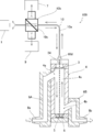
- FIG. 1 is a schematic diagram showing an overall configuration of a concentration measuring apparatus 100 according to Embodiment 1 of the present invention.
- the concentration measuring apparatus 100 includes a measuring cell 4 having an inflow port 4a, an outflow port 4b, and a flow path 4c for a fluid to be measured, and provided with a translucent window 3 in contact with the flow path 4c.
- a light source 1 that generates light that enters the measurement cell 4 through the window 3 and a light that propagates through the measurement cell 4 are reflected, and the reflected light is emitted from the measurement cell 4 through the window 3.
- a window part (not shown) may be provided in front of the reflecting member 5.
- light includes not only visible light, but also at least infrared rays and ultraviolet rays, and may include electromagnetic waves having an arbitrary wavelength.
- translucency means that the internal transmittance
- the calculation unit 8 may be configured using, for example, a processor or a memory provided on the circuit board PCB, and includes a computer program that executes a predetermined calculation based on an input signal, and includes hardware and software. It can be realized by a combination.
- the light source 1 has a plurality of light emitting elements 12 to 15, and the light emitting elements 12 to 15 are LEDs that emit light having different wavelengths.
- Each of the light emitting elements 12 to 15 is supplied with drive currents having different frequencies using an oscillation circuit.
- frequency analysis for example, fast Fourier transform or wavelet transform
- the intensity of light corresponding to each wavelength component can be measured from the detection signal detected by the measurement light detector 7.
- Lights of a plurality of wavelengths emitted from the light emitting elements 12 to 15 are combined by WDM (wavelength division multiplexing) multiplexers 17, 18, and 19 and are incident on the measurement cell 4.
- WDM wavelength division multiplexing
- the light wavelength of the light emitting element 12 is 255 nm
- the light wavelength of the light emitting element 13 is 280 nm
- the light wavelength of the light emitting element 14 is 310 nm
- the light wavelength of the light emitting element 15 is 365 nm.
- the driving current frequency of the element 12 is 216 Hz
- the driving current frequency of the light emitting element 13 is 192 Hz
- the driving current frequency of the light emitting element 14 is 168 Hz
- the driving current frequency of the light emitting element 15 is 144 Hz.
- the light source 1 is configured to output ultraviolet light including a plurality of wavelength components.
- the light emitting elements 12 to 15 light emitting elements other than LEDs, for example, LD (laser diode) can be used.
- a concentration measuring apparatus that uses multi-wavelength combined ultraviolet light as measuring light is disclosed in, for example, Patent Document 2 (International Publication No. 2017/029792), and the same light source, arithmetic unit, and the like are also used in the present invention. can do.
- Patent Document 2 International Publication No. 2017/029792
- the entire disclosure of WO 2017/029792 is incorporated herein by reference.
- a single wavelength light source can be used instead of a plurality of combined lights having different wavelengths as a light source.
- a multiplexer and a frequency analysis circuit can be omitted.
- the combined light is formed using four light emitting elements is shown, but the combined light may be formed using any one to three of these light emitting elements. Needless to say, more than one light emitting element may be used.
- an optical device 10 including an optical fiber 10a that is a light guide member and a beam splitter 10b is provided between the light source 1 and the measurement cell 4.
- the light emitted from the light source 1 is guided to the window 3 of the measurement cell 4 by the optical device 10.
- the optical device 10 also has a function of guiding the light reflected by the reflecting member 5 to the measurement light detector 7.
- the beam splitter 10b can also branch a part of the light emitted from the light source 1 and enter the reference light detector 9 as reference light.
- the reference light detected by the reference light detector 9 is used for correcting the measurement light.
- an optical fiber is used as a light guide member.
- the present invention is not limited to this.
- a translucent member made of glass or the like can be used as the light guide member.
- FIG. 2 is a cross-sectional view schematically showing a main part of the concentration measuring apparatus 100.
- one end of the optical fiber 10a is attached to the measurement cell 4 by a connecting part 10d, and the other end is connected to the beam splitter 10b.
- An optical element 24 such as a collimating lens may be provided in the connection portion 10d to the measurement cell 4, and thereby, light is appropriately emitted into the measurement cell 4 and light from the measurement cell 4 is appropriately emitted. It can receive light.
- the beam splitter 10b transmits a part of the light emitted from the light source 1 and emits the light to the optical fiber 10a, and reflects the light reflected from the reflecting member 5 and returned from the measurement cell 4 through the optical fiber 10a.
- a 50% reflection filter 10c may be provided in order to transmit and reflect light, for example.
- the measurement cell 4 has a flow path 4c through which gas flows from the inlet 4a to the outlet 4b, and the inlet 4a and the outlet 4b are provided apart from each other at both ends of the measurement cell 4.
- the inflow port 4 a is disposed in the vicinity of the window portion 3
- the outflow port 4 b is disposed in the vicinity of the reflecting member 5.
- the measurement cell 4 has a vertical configuration, and the flow path 4c extends in the vertical direction.
- the concentration measuring apparatus 100 can measure the concentration in a state where the gas to be measured flows through the vertical flow path 4c.
- the measurement cell 4 of the present embodiment has a first flow path forming member 8A (for example, a pipe or a flow path block) provided outside the inflow port 4a and an outside of the outflow port 4b.
- the second flow path forming member 8B is provided, and the first flow path forming member 8A and the second flow path forming member 8B have line connecting portions 8a to the gas supply line, respectively. 8b is provided.
- the concentration measuring apparatus 100 is configured to flow gas in the horizontal direction (arrangement direction of the line connecting portions 8a and 8b) as a whole when it is incorporated in the gas supply line.
- the flow path 4c of the measurement cell 4 extends in a direction orthogonal to the entire flow direction in the gas supply line, and such a configuration is used for the vertical measurement cell 4 or the flow path 4c extending in the vertical direction. I call it.
- the present invention is not limited to this, and the flow path 4c only needs to extend in a direction that forms an angle of, for example, 45 ° or more, and preferably an angle of 60 ° or more with respect to the entire flow direction. If the measurement cell 4 is used, it is possible to realize a countermeasure for dead space and space saving when incorporated in the gas supply line, and to obtain an advantage that maintenance is easy.
- the positions of the window 3 and the reflecting member 5 may be reversed.
- the positions of the inlet 4a and the outlet 4b are also reversed.
- the inflow port 4a is provided in the vicinity of the window 3 and the outflow port 4b is provided in the vicinity of the reflecting member 5.
- the inflow port 4a is provided in the vicinity of the reflecting member 5, and the window portion. 3 may be provided with an outlet 4b.
- the measurement cell 4 is provided with a window portion (translucent plate) 3 for light incidence and light emission.
- a window portion transparent plate
- sapphire glass which is resistant to detection light used for concentration measurement such as ultraviolet light and has high transmittance and is mechanically and chemically stable is preferably used.
- quartz glass can also be used.
- the body (flow path forming part) of the measurement cell 4 may be made of, for example, SUS316L.
- the window 3 and the reflecting member 5 are arranged to face each other with the flow path 4c interposed therebetween.
- the reflecting member 5 is provided such that the reflecting surface is perpendicular to the traveling direction of the incident light. For this reason, the reflected light is reflected to the window portion 3 through substantially the same optical path as the incident light.
- the reflection side window 6 is disposed with a gap in front of the reflection member 5, and sapphire glass is also preferably used as the reflection side window 6.
- the present invention is not limited to this mode, and the reflection member 5 may be configured to include the reflection-side window 6.
- the reflection member 5 has a configuration in which an aluminum layer as a reflection layer is formed on the back surface of sapphire glass by sputtering. You may do it.
- the reflection member 5 may have a configuration in which a reflection mirror is disposed on the back surface of the sapphire glass.
- the reflection member 5 may include a dielectric multilayer film as a reflection layer. If the dielectric multilayer film is used, light in a specific wavelength region (for example, near ultraviolet rays) can be selectively reflected. .
- the dielectric multilayer film is composed of a laminate of a plurality of optical coatings having different refractive indexes (for example, a laminate of a high refractive index thin film and a low refractive index thin film), and the thickness and refractive index of each layer are appropriately set. By selecting, light of a specific wavelength can be reflected or transmitted.
- the dielectric multilayer film can reflect light at an arbitrary ratio, for example, when incident light is reflected by the reflecting member 5, the incident light is not reflected 100% but partially ( (For example, 10%) is transmitted and receives light transmitted by an optical device (not shown) installed under the reflecting member 5 (position facing the reflecting-side window 6 when viewed from the reflecting member 5). You can also Then, the transmitted light can be used as reference light, and an optical device can be substituted for the reference light detector 9. Alternatively, since the transmitted light is light after passing through the gas in the measurement cell 4 and receiving light absorption by the gas, the concentration of the gas may be calculated using the transmitted light. In that case, you may make it monitor the temporal change of the reflection member 5 or the reflection side window part 6 using the reflected light.
- the reflecting member 5 may be configured by a retroreflecting plate (for example, a corner cube array). If the retroreflecting plate is used, the light can be retroreflected in the vicinity of the light incident position even when the reflecting surface is not arranged perpendicular to the light incident direction. The arrangement can be designed more freely.
- a retroreflecting plate for example, a corner cube array
- the window 3 is arranged on a plane perpendicular to the traveling direction of incident light in the illustrated embodiment, but may be arranged so as to be slightly tilted from the vertical plane in other embodiments. As a result, the light reflected by the window 3 is prevented from entering the optical device 10 as detection light, so that the measurement accuracy can be improved.
- the optical path length of the light propagating in the measurement cell 4 can be defined by twice the distance between the window 3 and the surface of the reflecting member 5.
- the optical path length of the light passing through the gas (Sometimes referred to as the optical path length of the measurement cell) can be defined as twice the distance between the window 3 and the reflection-side window 6.
- the concentration measuring apparatus 100 In the concentration measuring apparatus 100 described above, light having an absorption wavelength component out of light incident on the measurement cell 4 and then reflected by the reflecting member 5 is absorbed by the gas present in the flow path 4 c in the measurement cell 4. The The magnitude of absorption depends on the gas concentration.
- the calculating part 8 (refer FIG. 1) can measure the light absorbency A (lambda) in the said absorption wavelength by frequency-analyzing the detection signal from the measurement light detector 7, Furthermore, following formula
- the gas concentration C can be calculated from the absorbance A ⁇ based on the Lambert-Beer law shown in FIG.
- I 0 is the intensity of incident light incident on the measurement cell
- I is the intensity of light that has passed through the gas in the measurement cell
- ⁇ is the molar extinction coefficient (m 2 / mol)
- L is The optical path length (m) and C of the measurement cell are concentrations (mol / m 3 ).
- the molar extinction coefficient ⁇ is a coefficient determined by the substance.
- the incident light intensity I 0 in the above formula when there is no light-absorbing gas in the measurement cell 4 (for example, when a purge gas that does not absorb ultraviolet light is filled or when it is evacuated)
- the intensity of the light detected by the measurement light detector 7 may be regarded as the incident light intensity I 0 .
- the optical path length L of the measurement cell 4 can be defined as twice the distance between the window 3 and the reflection-side window 6 as described above, the light entrance window and the light exit window are measured.
- the optical path length can be doubled as compared with the conventional concentration measuring device provided on both sides of the cell. Thereby, the measurement accuracy can be improved in spite of the miniaturization.
- the concentration measuring apparatus 100 light incidence and light reception are performed using only one optical device 10 through one window 3 provided on one side of the measurement cell 4, so that the number of parts can be reduced.
- the reflecting member 5 includes a translucent plate 30 made of sapphire glass and an aluminum layer 31 as a reflective layer provided on the back surface of the translucent plate 30. .
- the reflection member 5 is attached to the measurement cell 4, but can be attached so as to be in contact with the gas flow path 4c without providing the reflection side window portion 6 as shown in FIG.
- the aluminum layer 31 exhibits a high reflectance (for example, 90% or more) with respect to ultraviolet light, but can be a factor for mixing aluminum into the gas flowing through the flow path.
- the reflection member 5 preferably has a front / back identification structure for identifying the surface provided with the reflection layer (aluminum layer) from the other surface.
- one orientation flat (a flat surface provided on the side surface of the translucent plate 30) 32 and one through hole 33 are formed on the surface of the translucent plate 30. It is provided at a position that does not oppose the center of the translucent plate 30 above (ie, asymmetrically). In this way, when two front and back identification structures that can be distinguished from each other are used, if they are arranged so as not to face each other and a corresponding fitting shape is provided on the tray side of the measurement cell 4, the front and back of the reflecting member 5 are mistaken. This prevents the aluminum from being mixed into the gas.
- FIG. 3B shows a mode in which one orientation flat 32 and one convex portion 34 are provided as the front and back identification structure. By arranging these so as not to face each other across the center on the translucent plate 30, they can function as a front / back identification structure.
- the three orientation flats 32, the three through holes 33, or the three protrusions 34 are asymmetric. That is, it can be made to function as a front / back identification structure by arranging asymmetrically so as not to be line symmetric with respect to an arbitrary axis passing through the center of the translucent plate 30 on the surface of the translucent plate 30. . Needless to say, four or more front and back identification structures may be provided.
- the orientation flat 32, the through-hole 33, and a combination thereof from the viewpoint of the manufacturing process, but the front / back identification structure may be various modes.
- a recess may be used instead of the through hole 33, and a cutout portion or a corner portion may be provided on the side surface instead of the orientation flat 32.
- a tapered chamfered portion or a stepped notch portion may be formed along the peripheral edge of one surface of the translucent plate 30.
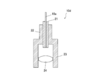
- connection portion 10d for attaching the optical device 10 to the measurement cell 4
- the connecting portion 10d is a portion arranged in the vicinity of the window portion 3 of the measurement cell 4, and the concentration of the measurement target gas flowing through the measurement cell 4 is high and accurate even when the gas to be measured is hot. It is preferably designed to allow measurement.
- the connecting part 10d of the optical device 10 includes an inner cylindrical part 21 as a protective member covering the end of the optical fiber 10a, a holding part 22 of the inner cylindrical part 21, and an optical element 24 inside. And a fixed distal end cylindrical portion 23.
- the holding part 22, the inner cylinder part 21, and the tip cylinder part 23 may be made of stainless steel (SUS316L or SUS304), for example.
- the optical fiber 10a may have a polyimide layer as a coating layer on the outer peripheral surface.
- the core and clad of the optical fiber 10a may be made of, for example, quartz.
- the optical element 24 is a collimating lens made of quartz, and is fixed to the inner side of the distal end cylindrical portion 23 by, for example, an epoxy resin.
- the connecting portion 10d constitutes a collimator.
- connection part 10d is comprised by the cylindrical metal member which protects the optical fiber 10a, even if it is a case where high temperature gas flows through the measurement cell 4 after attaching to a concentration measurement apparatus, The connection portion 10d is not damaged, and a high detection light output can be maintained.
- the optical device 10 described above it is possible to cope with not only a material that is gaseous at low and normal temperatures, but also high-temperature gas that is vaporized by heating, for example, up to 200 ° C., and can measure the concentration of the fluid to be measured in a wide range of applications. Can be performed with high accuracy.
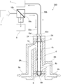
- the concentration measuring apparatus 200 of the present embodiment is different from the concentration measuring apparatus 100 of Embodiment 1 in terms of the configuration of the optical instrument.
- the configuration of the measurement cell 4 and the like is the same as that of the first embodiment, the same reference numerals are given and detailed description is omitted.
- an optical fiber bundle 40 configured by bundling a plurality of optical fibers is used for connection between the light source 1 and the measurement light detector 7 and the measurement cell 4.
- the optical fiber bundle 40 includes at least one optical fiber 40a for emitting light and at least one optical fiber 40b for receiving reflected light.
- each reflected light receiving optical fiber 40b are disposed so as to surround the periphery of one light emitting optical fiber 40a.
- light can be incident on the measurement cell 4 from the central portion, and reflected light can be received by the optical fiber 40b disposed in the periphery.
- the configuration of the optical fiber bundle 40 is not limited to the illustrated embodiment, and the number and arrangement of the light emitting optical fibers 40a and the light receiving optical fibers 40b may be arbitrary.
- the one end side of the optical fiber bundle 40 is attached to the measurement cell 4 by the connecting portion 10d as in the first embodiment. Moreover, the other end side of the optical fiber bundle 40 is branched in the middle in this embodiment. In the branched optical fiber, the end of the light incident optical fiber 40 a is connected to the beam splitter 10 b, and the end of the reflected light receiving optical fiber 40 b is connected to the measurement light detector 7.
- the beam splitter 10b splits the light from the light source 1 into the reference light and the incident light to the measurement cell 4, but unlike the first embodiment, the beam splitter 10b does not receive the reflected light from the measurement cell 4 and reflects the reflected light. Is directly output to the measurement light detector 7. For this reason, the reflected light is further reflected by the beam splitter 10b for guiding the light to the measurement light detector 7, and the output is not lowered, so that a higher detection light output can be obtained.
- the concentration measuring apparatus 300 of the present embodiment uses the reflecting member 60 composed of a prism or the like, and the incident light and the reflected light are parallel to each other in the measurement cell 4. It is configured to pass through different optical paths. Note that the configuration for performing density measurement using light reflected by the prism is disclosed in, for example, Patent Document 3, but the density measurement device disclosed in Patent Document 3 is inline as in the present embodiment. It is not a concentration measuring device of the formula.
- the inlet 4a and the outlet 4b communicating with the flow path 4c are separated at both ends of the measurement cell 4 as in the first embodiment.
- the flow path 4c has a vertical configuration extending in the vertical direction.
- the inflow port 4 a is disposed in the vicinity of the window portion 3, and the outflow port 4 b is disposed in the vicinity of the reflecting member 60. In this configuration, when incorporated in the gas supply line, it is possible to realize an advantage that space saving can be realized and maintenance is easy.
- an optical fiber 50a for light incidence and an optical fiber 50b for light reception are respectively attached to the measurement cell 4 by separate connection portions 10d (and optical elements 24). That is, in the concentration measuring apparatus 300, the first optical device that guides the light emitted from the light source 1 to the window 3 of the measurement cell 4 and the light emitted from the window 3 of the measurement cell 4 are detected by the measurement light. A second optical device for guiding light to the device 7 is provided separately. However, each of the connection portions 10d of each optical device is disposed at one end portion (in the vicinity of the window portion 3) of the vertical measurement cell 4, and also in this configuration, the entire concentration measurement apparatus 300 can be reduced in size. ing.
- the light emitted from the optical fiber 50a of the first optical device travels toward the reflecting member 60 along the flow path 4c through the optical element 24 and the window 3.
- the incident light travels in the same direction as the gas flow in the measurement cell 4.
- the light reflected by the reflecting member 60 travels toward the connecting portion 10d of the second optical device (optical fiber 50b) through a different optical path parallel to the incident light.
- the reflected light travels in the direction opposite to the gas flow in the measurement cell 4.
- the direction of gas flow may be opposite to the illustrated direction (that is, the inflow port 4a may be provided in the vicinity of the reflecting member 5 and the outflow port 4b may be provided in the vicinity of the window portion 3).
- the traveling direction of the incident light is opposite to the gas flow
- the traveling direction of the reflected light is the same direction as the gas flow.
- either incident light or reflected light in the measurement cell 4 travels in the same direction as the gas flow, and the other is opposite to the gas flow. Proceed in the direction of. Thereby, even if it is an in-line type concentration measuring apparatus, the stable concentration measurement which is hard to be influenced by the flow of gas can be performed.
- the reflecting member 60 may be constituted by, for example, a triangular prism, and is reflected twice by two reflecting surfaces of the prism as shown in FIG. 6 so that it passes through another optical path parallel to the optical path of the incident light.
- the reflected light travels.
- the prism may be fitted into a concave portion of a metallic holding member, or may be provided with its reflecting surface exposed so as to be in contact with a low refractive index medium such as air.
- a metal film or a dielectric multilayer film as a reflection layer may be formed on the reflection surface of the prism.
- FIG. 6 shows a mode in which the prism as the reflection member 60 and the reflection side window 6 are separately provided. However, these are integrally formed, and the back side of the reflection side window 6 is formed.
- a prism member provided with a prism structure may be used as the reflecting member 60.
- the concentration measurement apparatus 400 of the present embodiment is configured such that incident light and reflected light pass through different optical paths in the measurement cell 4 using the reflection member 70. ing.
- the concentration measuring apparatus 400 is a first optical device (light incident optical fiber) that guides the light emitted from the light source 1 to the window 3 of the measuring cell 4. 50a) and a second optical device (light receiving optical fiber 50b) for guiding the light emitted from the window 3 of the measurement cell 4 to the measurement light detector 7 are separately provided.
- the inlet 4a and the outlet 4b communicating with the flow path 4c are provided separately at both ends of the measurement cell 4, and the flow path 4c is formed. It has a vertical configuration extending in the vertical direction.
- the inflow port 4a (or the outflow port 4b) is disposed in the vicinity of the window portion 3, and the outflow port 4b (or the inflow port 4a) is disposed in the vicinity of the reflecting member 60.
- the reflecting member 70 has a reflecting surface arranged so as to be slightly inclined from a surface perpendicular to the traveling direction of incident light.
- the reflecting surface of the reflecting member 70 is formed of a dielectric multilayer film (for example, a laminate of a high refractive index thin film and a low refractive index thin film).
- the inclination angle of the reflecting surface can be determined from, for example, the distance from the connecting portion 10d of the first optical device to the reflecting surface and the distance between the connecting portions 10d of each optical device.
- the reflected light is guided to the second optical device through an optical path different from the incident light, and is separately reflected without being reflected by the beam splitter 10b as in the first embodiment. It is detected by the provided measuring light detector 7. Thereby, it is possible to detect a higher light output.
- FIG. 7 shows a mode in which the traveling direction of the incident light is the vertical direction in the drawing and the reflecting surface of the reflecting member 70 is inclined.
- the traveling direction of the incident light is shown. May be set to an oblique direction, and the reflecting surface of the reflecting member 70 may be set to a horizontal plane.
- the optical axis of the optical element 24 provided with respect to the first optical member is slightly tilted from the vertical direction to the left side, and the second optical member.
- the optical axis of the optical element 24 provided with respect to may be slightly inclined from the vertical direction to the right side.
- the optical path length of the measurement cell 4 is the distance between the window 3 and the reflection-side window 6 when the length of the measurement cell 4 is sufficiently larger than the distance between the connection portions 10d. It can be approximated by twice L 3-6 , but when the length of the measurement cell 4 is relatively short, the distance L 3-6 between the window 3 and the reflection side window 6 and L 3 ⁇ 6 / cos ⁇ (where ⁇ is the angle of inclination of the reflecting surface) and the sum (L 3-6 + L 3-6 / cos ⁇ ).
- the concentration measuring apparatus 500 of the present embodiment also includes a first optical device (light incident optical fiber 50a) that guides light from the light source 1 to the measurement cell 4, and the measurement cell 4. And a second optical device (light receiving optical fiber 50b) for guiding the light emitted from the measuring light detector 7 to the measurement light detector 7, and the light paths incident on the measurement cell 4 and the reflected light are different from each other. It is configured to pass.
- a first optical device light incident optical fiber 50a
- a second optical device for guiding the light emitted from the measuring light detector 7 to the measurement light detector 7, and the light paths incident on the measurement cell 4 and the reflected light are different from each other. It is configured to pass.
- an inflow port 4a and an outflow port 4b communicating with the flow channel 4c are provided apart from each other at both ends of the measurement cell 4, and the flow channel 4c extends in the vertical direction. It has a configuration.
- the inflow port 4 a (or the outflow port 4 b) is disposed in the vicinity of the window portion 3, and the outflow port 4 b (or the inflow port 4 a) is disposed in the vicinity of the reflecting member 5.
- the optical element 54 that receives the light emitted from the first optical device and enters the measurement cell 4 and receives the reflected light from the measurement cell 4 and enters the second optical device is a window portion. 3 is provided in the vicinity.
- the optical element 54 may be a lens that collimates incident light, and is provided in common for the first optical device and the second optical device.
- the optical axis 54x of the optical element 54 is disposed between the first optical device and the second optical device. At this time, the center of the range in which the light emitted from the first optical device irradiates the optical element 54 is formed at a position away from the center (on the optical axis) of the optical element 54.
- the light refracted by the optical element 54 travels in the measurement cell 4 in an oblique direction inclined from the vertical direction, and the light reflected by the reflecting member 5 passes through an optical path different from the incident light. And proceed diagonally. Then, after entering the optical element 54 again, it is refracted by the optical element 54 and is condensed to the second optical device.
- the concentration measuring apparatus according to the first to fifth embodiments of the present invention has been described above.
- the present invention is not limited to the above-described embodiment, and various modifications can be made without departing from the spirit of the present invention. is there.
- light used for measurement light in a wavelength region other than the ultraviolet region can be used.
- the concentration measuring apparatus is incorporated in a gas supply line used in a semiconductor manufacturing apparatus or the like, and is preferably used for measuring the concentration of gas flowing through a flow path.
Landscapes
- Physics & Mathematics (AREA)
- Health & Medical Sciences (AREA)
- Life Sciences & Earth Sciences (AREA)
- Chemical & Material Sciences (AREA)
- Analytical Chemistry (AREA)
- Biochemistry (AREA)
- General Health & Medical Sciences (AREA)
- General Physics & Mathematics (AREA)
- Immunology (AREA)
- Pathology (AREA)
- Spectroscopy & Molecular Physics (AREA)
- Investigating Or Analysing Materials By Optical Means (AREA)
- Optical Measuring Cells (AREA)
Abstract
Description
図1は、本発明の実施形態1による濃度測定装置100の全体構成を示す模式図である。濃度測定装置100は、被測定流体の流入口4a、流出口4bおよび流路4cを有し、流路4cに接する透光性の窓部3が設けられた測定セル4と、透光性の窓部3を通して測定セル4内に入射させる光を発生させる光源1と、測定セル4内を伝播する光を反射し、反射した光を窓部3を介して測定セル4から出射させるように構成された反射部材5と、反射部材5によって反射され測定セル4から出射した光を検出する測定光検出器7と、測定光検出器7の検出信号に基づいて被測定流体の濃度を演算する演算部8と、光源1からの参照光を検出する参照光検出器9と、温度センサ11とを備えている。なお、反射部材5の前には、窓部(図示せず)が設けられていてもよい。
上記の式(1)において、I0は測定セルに入射する入射光の強度、Iは測定セル内のガス中を通過した光の強度、αはモル吸光係数(m2/mol)、Lは測定セルの光路長(m)、Cは濃度(mol/m3)である。モル吸光係数αは物質によって決まる係数である。
以下、図5(a)および(b)を参照しながら、実施形態2の濃度測定装置200を説明する。
以下、図6を参照しながら、実施形態3の濃度測定装置300を説明する。実施形態1と同様の構成要素については、同じ参照符号を付すとともに詳細な説明を省略する。
以下、図7を参照しながら、実施形態4の濃度測定装置400を説明するが、実施形態1~3と同様の構成要素については同じ参照符号を付すとともに詳細な説明を省略する。
以下、図8を参照しながら、実施形態5の濃度測定装置500を説明するが、実施形態1~4と同様の構成要素については同じ参照符号を付すとともに詳細な説明を省略する。
3 窓部
4 測定セル
4a 流入口
4b 流出口
4c 流路
5 反射部材
6 反射側窓部
7 測定光検出器
8 演算部
8A 第1の流路形成部材
8B 第2の流路形成部材
10 光学機器
10a 光ファイバ
10b ビームスプリッタ
10d 接続部
24 光学素子
50a 光入射用光ファイバ(第1の光学機器)
50b 受光用光ファイバ(第2の光学機器)
100 濃度測定装置
Claims (15)
- 被測定流体の流路および前記流路に接する透光性の窓部を有する測定セルと、
前記測定セルに前記窓部を介して入射する光を発する光源と、
前記測定セル内を伝播する前記光を反射し、前記反射した前記光を前記窓部を介して前記測定セルから出射させる反射部材と、
前記測定セルの前記窓部から出射した光を検出する光検出器と、
前記光検出器の検出信号に基づいて前記被測定流体の濃度を演算する演算部と、
前記光源から発せられた前記光を前記測定セルの前記窓部に導光するとともに前記測定セルの窓部から出射した光を前記光検出器に導光する光学機器と
を備える、濃度測定装置。 - 前記反射部材は、前記流路を挟んで前記窓部と対向するように配置されている、請求項1に記載の濃度測定装置。
- 前記光学機器は、導光部材と、前記導光部材に接続されたビームスプリッタとを有し、
前記ビームスプリッタは、前記光源からの前記光を受け取り前記導光部材を介して前記測定セルに入射させるとともに、前記測定セルから出射され前記導光部材によって導かれた前記光を受け取り前記光検出器に入射させる、請求項1または2に記載の濃度測定装置。 - 前記光学機器は、前記光源から発せられた前記光を前記測定セルの前記窓部に導光するための光出射用の光ファイバと、前記測定セルの窓部から出射された前記光を前記光検出器に導光するための受光用の光ファイバとを含む光ファイババンドルを有している、請求項1または2に記載の濃度測定装置。
- 前記測定セルの両端部において前記流路に連通する流入口と流出口とが設けられている請求項1から4のいずれかに記載の濃度測定装置。
- 前記流入口および前記流出口のうちのいずれか一方は前記窓部の近傍に配置され、他方は前記反射部材の近傍に配置されている、請求項5に記載の濃度測定装置。
- 前記光は紫外光であり、前記反射部材はアルミニウムを含む材料から形成された反射層または誘電体多層膜からなる反射層を含む、請求項1から6のいずれかに記載の濃度測定装置。
- 前記反射部材は、透光性プレートと、前記透光性プレートの片面に設けられた反射層とを有し、前記反射層が設けられた面を他方の面と識別するための表裏識別構造を有している、請求項1から7のいずれかに記載の濃度測定装置。
- 前記表裏識別構造は、前記透光性プレートの側面に設けられた平坦面、前記透光性プレートに設けられた凹部または貫通孔、もしくは、前記透光性プレートに設けられた凸部のうちのいずれかを、非対称に配置することによって構成されている、請求項8に記載の濃度測定装置。
- 被測定流体の流路および前記流路に接する透光性の窓部を有する測定セルと、
前記測定セルに前記窓部を介して入射する光を発する光源と、
前記測定セル内を伝播する前記光を反射し、前記反射した前記光を前記窓部を介して前記測定セルから出射させる反射部材と、
前記測定セルの前記窓部から出射した前記光を検出する光検出器と、
前記光検出器の検出信号に基づいて前記被測定流体の濃度を演算する演算部と、
前記光源から発せられた前記光を前記測定セルの前記窓部に導光する第1の光学機器、および、前記測定セルの窓部から出射された光を前記光検出器に導光する第2の光学機器と
を備え、
前記反射部材は、前記第1の光学機器から入射し前記測定セルの前記流路内を伝播したた入射光を受け、前記入射光の光路と異なる光路を通って前記第2の光学機器へと反射光を反射させるように構成されており、
前記測定セルの両端部において前記流路に連通する流入口と流出口とが設けられ、前記流入口および前記流出口のうちのいずれか一方は前記窓部の近傍に配置され、他方は前記反射部材の近傍に配置されている、濃度測定装置。 - 前記光源からの前記光を分岐し、参照光として参照光検出器に入射させる、請求項10に記載の濃度測定装置。
- 前記反射光の前記光路は、前記入射光の前記光路と平行である、請求項10または11に記載の濃度測定装置。
- 前記反射部材は、三角柱状のプリズムを含む、請求項12に記載の濃度測定装置。
- 前記反射部材は、前記入射光の進行方向に対して垂直な面から傾いた反射面を含む、請求項10または11に記載の濃度測定装置。
- 前記窓部の近傍に設けられ、前記第1の光学機器からの前記出射光を受けて前記測定セルに入射させるとともに、前記測定セルからの前記反射光を受けて前記第2の光学機器に入射させる光学素子をさらに有し、前記光学素子の光軸が、前記第1の光学機器と前記第2の光学機器との間に配されている、請求項10または11に記載の濃度測定装置。
Priority Applications (3)
| Application Number | Priority Date | Filing Date | Title |
|---|---|---|---|
| CN201780018319.9A CN109477791A (zh) | 2016-07-29 | 2017-07-25 | 浓度测定装置 |
| KR1020187024156A KR102246478B1 (ko) | 2016-07-29 | 2017-07-25 | 농도 측정 장치 |
| US16/320,002 US10928303B2 (en) | 2016-07-29 | 2017-07-25 | Concentration measuring device |
Applications Claiming Priority (2)
| Application Number | Priority Date | Filing Date | Title |
|---|---|---|---|
| JP2016149189A JP6912766B2 (ja) | 2016-07-29 | 2016-07-29 | 濃度測定装置 |
| JP2016-149189 | 2016-07-29 |
Publications (1)
| Publication Number | Publication Date |
|---|---|
| WO2018021311A1 true WO2018021311A1 (ja) | 2018-02-01 |
Family
ID=61016130
Family Applications (1)
| Application Number | Title | Priority Date | Filing Date |
|---|---|---|---|
| PCT/JP2017/026868 Ceased WO2018021311A1 (ja) | 2016-07-29 | 2017-07-25 | 濃度測定装置 |
Country Status (6)
| Country | Link |
|---|---|
| US (1) | US10928303B2 (ja) |
| JP (1) | JP6912766B2 (ja) |
| KR (1) | KR102246478B1 (ja) |
| CN (1) | CN109477791A (ja) |
| TW (1) | TWI651529B (ja) |
| WO (1) | WO2018021311A1 (ja) |
Cited By (12)
| Publication number | Priority date | Publication date | Assignee | Title |
|---|---|---|---|---|
| WO2020066732A1 (ja) * | 2018-09-25 | 2020-04-02 | 株式会社フジキン | 濃度測定装置 |
| JPWO2020213385A1 (ja) * | 2019-04-19 | 2020-10-22 | ||
| WO2021019228A1 (en) * | 2019-07-29 | 2021-02-04 | Imperial College Innovations Limited | Method and apparatus for monitoring production of a material in a liquid dispersion in real time |
| KR20210027428A (ko) | 2018-09-28 | 2021-03-10 | 가부시키가이샤 후지킨 | 농도 측정 방법 |
| JPWO2021054097A1 (ja) * | 2019-09-18 | 2021-03-25 | ||
| KR20210048542A (ko) | 2018-10-26 | 2021-05-03 | 가부시키가이샤 후지킨 | 농도 측정 장치 |
| KR20210052550A (ko) | 2019-01-31 | 2021-05-10 | 가부시키가이샤 후지킨 | 농도 측정 장치 |
| KR20210091313A (ko) | 2019-03-29 | 2021-07-21 | 가부시키가이샤 후지킨 | 농도 측정 장치 |
| WO2021182279A1 (ja) * | 2020-03-13 | 2021-09-16 | 国立大学法人徳島大学 | 濃度測定方法および濃度測定装置 |
| KR20230140581A (ko) | 2021-07-31 | 2023-10-06 | 가부시키가이샤 후지킨 | 농도 측정 장치 |
| WO2024116593A1 (ja) * | 2022-11-30 | 2024-06-06 | 株式会社フジキン | 濃度測定装置 |
| KR20250002370A (ko) | 2022-07-19 | 2025-01-07 | 가부시키가이샤 후지킨 | 농도 측정 장치 및 그 이상 검지 방법 |
Families Citing this family (8)
| Publication number | Priority date | Publication date | Assignee | Title |
|---|---|---|---|---|
| JP7244900B2 (ja) * | 2018-12-27 | 2023-03-23 | 株式会社フジキン | 反射部材の表裏識別方法 |
| JP7364798B2 (ja) * | 2020-07-31 | 2023-10-18 | 株式会社日立ハイテク | キャピラリ電気泳動装置 |
| JP7590637B2 (ja) * | 2020-09-28 | 2024-11-27 | 東亜ディーケーケー株式会社 | 吸光度測定装置 |
| JP2023549475A (ja) * | 2020-10-20 | 2023-11-27 | ベクトン・ディキンソン・アンド・カンパニー | 傾斜ビーム成形光学部品を含むフローサイトメータ、及びフローサイトメータを使用する方法 |
| JP2022078594A (ja) * | 2020-11-13 | 2022-05-25 | 日本ピラー工業株式会社 | 液体センサ、及び、光導波路の製造方法 |
| JP2022185655A (ja) * | 2021-06-03 | 2022-12-15 | アズビル株式会社 | 光学分析装置 |
| KR102835691B1 (ko) * | 2022-06-16 | 2025-07-18 | 주식회사 에이티아이케이 | 농도 측정 장치 |
| KR102654207B1 (ko) * | 2023-09-11 | 2024-04-03 | (주)세성 | 극한환경 측정용 멀티채널 비분산적외선 가스측정 장치 |
Citations (11)
| Publication number | Priority date | Publication date | Assignee | Title |
|---|---|---|---|---|
| JPS5298478U (ja) * | 1976-01-22 | 1977-07-25 | ||
| JPS62145141U (ja) * | 1986-03-07 | 1987-09-12 | ||
| JPS6351260U (ja) * | 1986-09-22 | 1988-04-06 | ||
| JPH01295136A (ja) * | 1988-02-17 | 1989-11-28 | Kiyouseki Seihin Gijutsu Kenkyusho:Kk | エンジン油の劣化検出装置 |
| JPH04502511A (ja) * | 1988-12-22 | 1992-05-07 | ラジオメータ・アクチセルスカベット | 血液試料中における血液ガスパラメーターの光学的インビトロ測定法 |
| JPH0743291A (ja) * | 1993-07-28 | 1995-02-14 | Power Reactor & Nuclear Fuel Dev Corp | 吸光分析用プローブ |
| JPH0835930A (ja) * | 1993-08-09 | 1996-02-06 | Vickers Inc | 流体の汚染レベルの監視方法および装置 |
| US5693944A (en) * | 1994-09-02 | 1997-12-02 | Ntc Technology, Inc. | Gas analyzer cuvettes |
| JPH10135165A (ja) * | 1996-10-29 | 1998-05-22 | Komatsu Electron Metals Co Ltd | 半導体ウェハの製法 |
| JP2004138520A (ja) * | 2002-10-18 | 2004-05-13 | Mitsubishi Heavy Ind Ltd | N2o成分計測装置 |
| JP2011242281A (ja) * | 2010-05-19 | 2011-12-01 | Shimadzu Corp | ガスセル |
Family Cites Families (34)
| Publication number | Priority date | Publication date | Assignee | Title |
|---|---|---|---|---|
| US3740155A (en) * | 1971-04-01 | 1973-06-19 | Syntex Corp | Colorimeter probe |
| US4914297A (en) * | 1987-12-23 | 1990-04-03 | Nicolet Instrument Corporation | Infrared spectrometer interface for thermogravimetric analysis |
| US5376551A (en) * | 1991-03-12 | 1994-12-27 | University Of Utah Research Foundation | Apparatus for using fluorescently labeled ligands in studying interaction of a native ligand and its receptor |
| US5963336A (en) * | 1995-10-10 | 1999-10-05 | American Air Liquide Inc. | Chamber effluent monitoring system and semiconductor processing system comprising absorption spectroscopy measurement system, and methods of use |
| KR20030002047A (ko) * | 2001-06-30 | 2003-01-08 | 기우치 노리히로 | 액 농도 검출 방법 및 장치 |
| US7259856B2 (en) * | 2005-02-16 | 2007-08-21 | Picarro, Inc. | Method for the precise measurement of the wavelength of light |
| CN2879175Y (zh) * | 2005-08-02 | 2007-03-14 | 德菲电气(北京)有限公司 | 多组分紫外在线气体分析仪 |
| US7411668B2 (en) * | 2005-09-26 | 2008-08-12 | Zaps Technologies Incorporated | Light returning target for a photometer |
| US20090046287A1 (en) * | 2005-09-26 | 2009-02-19 | Haught Roy C | Zero angle photo spectrophotometer for monitoring of water systems |
| CN100561192C (zh) | 2006-07-06 | 2009-11-18 | 西安交通大学 | 基于aotf近红外光谱仪实现的多组分气体浓度定量分析方法 |
| US7728978B2 (en) * | 2006-10-18 | 2010-06-01 | Spectrasensors, Inc. | Detection of moisture in refrigerants |
| CN101178351A (zh) * | 2006-11-08 | 2008-05-14 | 汤知 | 光纤传感式ch4气体测量仪 |
| JP2009080017A (ja) * | 2007-09-26 | 2009-04-16 | Shimadzu Corp | 多重反射セル式ガス分析システム用のフローセル、多重反射セル式ガス分析システム及びフローセルのミラー間距離の調整方法 |
| CN201110831Y (zh) * | 2007-11-21 | 2008-09-03 | 大连理工大学 | 一种多用途高效荧光光纤化学与生物传感器组件 |
| CN201152458Y (zh) * | 2007-12-07 | 2008-11-19 | 中国科学技术大学 | 新型城市天然气管道泄漏检测定位系统 |
| CN101241068A (zh) * | 2008-03-13 | 2008-08-13 | 复旦大学 | 多光路光学吸收大气测量仪 |
| DE102008064173B4 (de) * | 2008-12-22 | 2011-06-01 | Universität Rostock | Verfahren und Vorrichtung zur Bestimmung der Stoffkonzentration in gasförmigen oder fluiden Medien mittels optischer Absorptionsspektroskopie mit Breitbandlichtquellen |
| US20100302546A1 (en) * | 2009-05-27 | 2010-12-02 | Masud Azimi | Optical measurement of samples |
| EP2538202A4 (en) * | 2010-02-16 | 2018-03-21 | Hamamatsu Photonics K.K. | Gas concentration calculation device and gas concentration measurement module |
| US8358417B2 (en) * | 2010-10-21 | 2013-01-22 | Spectrasensors, Inc. | Spectrometer with validation cell |
| CN102564999A (zh) * | 2010-12-15 | 2012-07-11 | 西安金和光学科技有限公司 | 一种气体传感装置 |
| US8981314B2 (en) * | 2011-02-10 | 2015-03-17 | Zaps Technologies, Inc | Method and apparatus for the optical determination of total organic carbon in aqueous streams |
| JP6091500B2 (ja) * | 2011-06-07 | 2017-03-08 | メジャメント スペシャリティーズ, インコーポレイテッド | 流体検出のための光検出装置、およびそのための方法 |
| US8547554B2 (en) * | 2011-08-17 | 2013-10-01 | General Electric Company | Method and system for detecting moisture in natural gas |
| JP6084399B2 (ja) | 2012-08-20 | 2017-02-22 | 株式会社四国総合研究所 | 光学式ガスセンサおよびガス濃度監視方法 |
| JP5885699B2 (ja) | 2013-05-09 | 2016-03-15 | 株式会社フジキン | 脆性破壊性光透過窓板の固定構造及びこれを用いた脆性破壊性光透過窓板の固定方法 |
| US9651467B2 (en) * | 2013-05-09 | 2017-05-16 | Tokushima University | Raw material fluid density detector |
| JP5973969B2 (ja) * | 2013-07-31 | 2016-08-23 | 国立大学法人徳島大学 | インライン型濃度計及び濃度検出方法 |
| EP3077797A4 (en) * | 2013-12-05 | 2017-09-27 | Gary P. Klinkhammer | Spectrophotometer with variable optical path length cell |
| US9194797B2 (en) * | 2013-12-20 | 2015-11-24 | General Electric Company | Method and system for detecting moisture in a process gas involving cross interference |
| US10024788B2 (en) * | 2015-05-04 | 2018-07-17 | Spectrasensors, Inc. | Spectrometer with random beam profiles |
| JP6811966B2 (ja) | 2015-08-18 | 2021-01-13 | 国立大学法人徳島大学 | 濃度測定装置 |
| CN105158191B (zh) * | 2015-09-01 | 2018-02-06 | 中国科学院合肥物质科学研究院 | 含砷精金矿焙烧炉内三氧化二砷气体的浓度检测装置 |
| CN105158206B (zh) * | 2015-10-17 | 2017-09-12 | 中国科学院合肥物质科学研究院 | 一种车载式机动车尾气中氧气浓度的激光检测系统 |
-
2016
- 2016-07-29 JP JP2016149189A patent/JP6912766B2/ja active Active
-
2017
- 2017-07-25 WO PCT/JP2017/026868 patent/WO2018021311A1/ja not_active Ceased
- 2017-07-25 CN CN201780018319.9A patent/CN109477791A/zh active Pending
- 2017-07-25 KR KR1020187024156A patent/KR102246478B1/ko active Active
- 2017-07-25 US US16/320,002 patent/US10928303B2/en active Active
- 2017-07-27 TW TW106125228A patent/TWI651529B/zh active
Patent Citations (11)
| Publication number | Priority date | Publication date | Assignee | Title |
|---|---|---|---|---|
| JPS5298478U (ja) * | 1976-01-22 | 1977-07-25 | ||
| JPS62145141U (ja) * | 1986-03-07 | 1987-09-12 | ||
| JPS6351260U (ja) * | 1986-09-22 | 1988-04-06 | ||
| JPH01295136A (ja) * | 1988-02-17 | 1989-11-28 | Kiyouseki Seihin Gijutsu Kenkyusho:Kk | エンジン油の劣化検出装置 |
| JPH04502511A (ja) * | 1988-12-22 | 1992-05-07 | ラジオメータ・アクチセルスカベット | 血液試料中における血液ガスパラメーターの光学的インビトロ測定法 |
| JPH0743291A (ja) * | 1993-07-28 | 1995-02-14 | Power Reactor & Nuclear Fuel Dev Corp | 吸光分析用プローブ |
| JPH0835930A (ja) * | 1993-08-09 | 1996-02-06 | Vickers Inc | 流体の汚染レベルの監視方法および装置 |
| US5693944A (en) * | 1994-09-02 | 1997-12-02 | Ntc Technology, Inc. | Gas analyzer cuvettes |
| JPH10135165A (ja) * | 1996-10-29 | 1998-05-22 | Komatsu Electron Metals Co Ltd | 半導体ウェハの製法 |
| JP2004138520A (ja) * | 2002-10-18 | 2004-05-13 | Mitsubishi Heavy Ind Ltd | N2o成分計測装置 |
| JP2011242281A (ja) * | 2010-05-19 | 2011-12-01 | Shimadzu Corp | ガスセル |
Cited By (40)
| Publication number | Priority date | Publication date | Assignee | Title |
|---|---|---|---|---|
| JPWO2020066732A1 (ja) * | 2018-09-25 | 2021-08-30 | 株式会社フジキン | 濃度測定装置 |
| WO2020066732A1 (ja) * | 2018-09-25 | 2020-04-02 | 株式会社フジキン | 濃度測定装置 |
| JP2023160991A (ja) * | 2018-09-25 | 2023-11-02 | 株式会社フジキン | 濃度測定装置 |
| KR20210002711A (ko) | 2018-09-25 | 2021-01-08 | 가부시키가이샤 후지킨 | 농도 측정 장치 |
| JP7360100B2 (ja) | 2018-09-25 | 2023-10-12 | 株式会社フジキン | 濃度測定装置 |
| KR20220140049A (ko) | 2018-09-25 | 2022-10-17 | 가부시키가이샤 후지킨 | 농도 측정 장치 |
| JP7563795B2 (ja) | 2018-09-25 | 2024-10-08 | 株式会社フジキン | 濃度測定装置 |
| KR102454649B1 (ko) * | 2018-09-25 | 2022-10-17 | 가부시키가이샤 후지킨 | 농도 측정 장치 |
| US11391668B2 (en) | 2018-09-25 | 2022-07-19 | Fujikin Incorporated | Concentration measurement device |
| KR102561924B1 (ko) * | 2018-09-25 | 2023-08-01 | 가부시키가이샤 후지킨 | 농도 측정 장치 |
| TWI721570B (zh) * | 2018-09-25 | 2021-03-11 | 日商富士金股份有限公司 | 濃度測定裝置 |
| US11630058B2 (en) | 2018-09-25 | 2023-04-18 | Fujikin Incorporated | Concentration measurement device |
| KR20210027428A (ko) | 2018-09-28 | 2021-03-10 | 가부시키가이샤 후지킨 | 농도 측정 방법 |
| US11460396B2 (en) | 2018-09-28 | 2022-10-04 | Fujikin Incorporated | Concentration measurement method |
| US11686671B2 (en) | 2018-10-26 | 2023-06-27 | Fujikin Incorporated | Concentration measurement device |
| KR20210048542A (ko) | 2018-10-26 | 2021-05-03 | 가부시키가이샤 후지킨 | 농도 측정 장치 |
| KR20210052550A (ko) | 2019-01-31 | 2021-05-10 | 가부시키가이샤 후지킨 | 농도 측정 장치 |
| US11796458B2 (en) | 2019-01-31 | 2023-10-24 | Fujikin Incorporated | Concentration measurement device |
| US12424468B2 (en) | 2019-03-29 | 2025-09-23 | Fujikin Incorporated | Concentration measurement device |
| KR20210091313A (ko) | 2019-03-29 | 2021-07-21 | 가부시키가이샤 후지킨 | 농도 측정 장치 |
| KR20210129150A (ko) | 2019-04-19 | 2021-10-27 | 가부시키가이샤 후지킨 | 농도 측정 장치 |
| JPWO2020213385A1 (ja) * | 2019-04-19 | 2020-10-22 | ||
| US11692931B2 (en) | 2019-04-19 | 2023-07-04 | Fujikin Incorporated | Concentration measurement device |
| JP7445313B2 (ja) | 2019-04-19 | 2024-03-07 | 株式会社フジキン | 濃度測定装置 |
| WO2020213385A1 (ja) * | 2019-04-19 | 2020-10-22 | 株式会社フジキン | 濃度測定装置 |
| US12117390B2 (en) | 2019-07-29 | 2024-10-15 | Imperial College Innovations Limited | Method and apparatus for monitoring production of a material in a liquid dispersion in real time |
| WO2021019228A1 (en) * | 2019-07-29 | 2021-02-04 | Imperial College Innovations Limited | Method and apparatus for monitoring production of a material in a liquid dispersion in real time |
| WO2021054097A1 (ja) * | 2019-09-18 | 2021-03-25 | 株式会社フジキン | 濃度測定装置 |
| JPWO2021054097A1 (ja) * | 2019-09-18 | 2021-03-25 | ||
| JP7492269B2 (ja) | 2019-09-18 | 2024-05-29 | 株式会社フジキン | 濃度測定装置 |
| US12105019B2 (en) | 2019-09-18 | 2024-10-01 | Fujikin Incorporated | Density measurement device |
| KR20220035249A (ko) | 2019-09-18 | 2022-03-21 | 가부시키가이샤 후지킨 | 농도 측정 장치 |
| US12078590B2 (en) | 2020-03-13 | 2024-09-03 | Tokushima University | Concentration measuring method, and concentration measuring device |
| KR20220079977A (ko) | 2020-03-13 | 2022-06-14 | 토쿠시마 대학 | 농도 측정 방법 및 농도 측정 장치 |
| WO2021182279A1 (ja) * | 2020-03-13 | 2021-09-16 | 国立大学法人徳島大学 | 濃度測定方法および濃度測定装置 |
| KR20230140581A (ko) | 2021-07-31 | 2023-10-06 | 가부시키가이샤 후지킨 | 농도 측정 장치 |
| US12492985B2 (en) | 2021-07-31 | 2025-12-09 | Fujikin Incorporated | Density measurement device |
| KR20250002370A (ko) | 2022-07-19 | 2025-01-07 | 가부시키가이샤 후지킨 | 농도 측정 장치 및 그 이상 검지 방법 |
| WO2024116593A1 (ja) * | 2022-11-30 | 2024-06-06 | 株式会社フジキン | 濃度測定装置 |
| KR20250021558A (ko) | 2022-11-30 | 2025-02-13 | 가부시키가이샤 후지킨 | 농도 측정 장치 |
Also Published As
| Publication number | Publication date |
|---|---|
| US10928303B2 (en) | 2021-02-23 |
| KR102246478B1 (ko) | 2021-04-30 |
| JP2018017644A (ja) | 2018-02-01 |
| US20190271636A1 (en) | 2019-09-05 |
| TW201816389A (zh) | 2018-05-01 |
| TWI651529B (zh) | 2019-02-21 |
| JP6912766B2 (ja) | 2021-08-04 |
| CN109477791A (zh) | 2019-03-15 |
| KR20180104090A (ko) | 2018-09-19 |
Similar Documents
| Publication | Publication Date | Title |
|---|---|---|
| JP6912766B2 (ja) | 濃度測定装置 | |
| JP6786099B2 (ja) | 濃度測定装置 | |
| US11630058B2 (en) | Concentration measurement device | |
| TWI762233B (zh) | 濃度測定方法及濃度測定裝置 | |
| KR102593815B1 (ko) | 농도 측정 장치 | |
| KR20100099989A (ko) | 편광각 투과 유도 프리즘 및 이를 이용한 신호 대 잡음비 향상을 위한 형광검출장치 | |
| US12105019B2 (en) | Density measurement device | |
| TWI756651B (zh) | 濃度測量裝置 | |
| US10025077B2 (en) | Device for measuring solution concentration | |
| JP7244900B2 (ja) | 反射部材の表裏識別方法 | |
| KR101824475B1 (ko) | 광섬유 센서 및 그를 포함하는 측정 장치 |
Legal Events
| Date | Code | Title | Description |
|---|---|---|---|
| ENP | Entry into the national phase |
Ref document number: 20187024156 Country of ref document: KR Kind code of ref document: A |
|
| WWE | Wipo information: entry into national phase |
Ref document number: 1020187024156 Country of ref document: KR |
|
| 121 | Ep: the epo has been informed by wipo that ep was designated in this application |
Ref document number: 17834313 Country of ref document: EP Kind code of ref document: A1 |
|
| NENP | Non-entry into the national phase |
Ref country code: DE |
|
| 122 | Ep: pct application non-entry in european phase |
Ref document number: 17834313 Country of ref document: EP Kind code of ref document: A1 |