WO2018012238A1 - 電気接続アセンブリの製造方法 - Google Patents
電気接続アセンブリの製造方法 Download PDFInfo
- Publication number
- WO2018012238A1 WO2018012238A1 PCT/JP2017/022977 JP2017022977W WO2018012238A1 WO 2018012238 A1 WO2018012238 A1 WO 2018012238A1 JP 2017022977 W JP2017022977 W JP 2017022977W WO 2018012238 A1 WO2018012238 A1 WO 2018012238A1
- Authority
- WO
- WIPO (PCT)
- Prior art keywords
- connector
- conductors
- terminals
- insulating housing
- wiring member
- Prior art date
- Legal status (The legal status is an assumption and is not a legal conclusion. Google has not performed a legal analysis and makes no representation as to the accuracy of the status listed.)
- Ceased
Links
Images


Classifications
-
- H—ELECTRICITY
- H01—ELECTRIC ELEMENTS
- H01R—ELECTRICALLY-CONDUCTIVE CONNECTIONS; STRUCTURAL ASSOCIATIONS OF A PLURALITY OF MUTUALLY-INSULATED ELECTRICAL CONNECTING ELEMENTS; COUPLING DEVICES; CURRENT COLLECTORS
- H01R4/00—Electrically-conductive connections between two or more conductive members in direct contact, i.e. touching one another; Means for effecting or maintaining such contact; Electrically-conductive connections having two or more spaced connecting locations for conductors and using contact members penetrating insulation
- H01R4/02—Soldered or welded connections
- H01R4/023—Soldered or welded connections between cables or wires and terminals
- H01R4/024—Soldered or welded connections between cables or wires and terminals comprising preapplied solder
-
- H—ELECTRICITY
- H01—ELECTRIC ELEMENTS
- H01R—ELECTRICALLY-CONDUCTIVE CONNECTIONS; STRUCTURAL ASSOCIATIONS OF A PLURALITY OF MUTUALLY-INSULATED ELECTRICAL CONNECTING ELEMENTS; COUPLING DEVICES; CURRENT COLLECTORS
- H01R4/00—Electrically-conductive connections between two or more conductive members in direct contact, i.e. touching one another; Means for effecting or maintaining such contact; Electrically-conductive connections having two or more spaced connecting locations for conductors and using contact members penetrating insulation
- H01R4/02—Soldered or welded connections
- H01R4/029—Welded connections
-
- H—ELECTRICITY
- H01—ELECTRIC ELEMENTS
- H01R—ELECTRICALLY-CONDUCTIVE CONNECTIONS; STRUCTURAL ASSOCIATIONS OF A PLURALITY OF MUTUALLY-INSULATED ELECTRICAL CONNECTING ELEMENTS; COUPLING DEVICES; CURRENT COLLECTORS
- H01R13/00—Details of coupling devices of the kinds covered by groups H01R12/70 or H01R24/00 - H01R33/00
- H01R13/648—Protective earth or shield arrangements on coupling devices, e.g. anti-static shielding
- H01R13/658—High frequency shielding arrangements, e.g. against EMI [Electro-Magnetic Interference] or EMP [Electro-Magnetic Pulse]
-
- H—ELECTRICITY
- H01—ELECTRIC ELEMENTS
- H01R—ELECTRICALLY-CONDUCTIVE CONNECTIONS; STRUCTURAL ASSOCIATIONS OF A PLURALITY OF MUTUALLY-INSULATED ELECTRICAL CONNECTING ELEMENTS; COUPLING DEVICES; CURRENT COLLECTORS
- H01R4/00—Electrically-conductive connections between two or more conductive members in direct contact, i.e. touching one another; Means for effecting or maintaining such contact; Electrically-conductive connections having two or more spaced connecting locations for conductors and using contact members penetrating insulation
- H01R4/02—Soldered or welded connections
-
- H—ELECTRICITY
- H01—ELECTRIC ELEMENTS
- H01R—ELECTRICALLY-CONDUCTIVE CONNECTIONS; STRUCTURAL ASSOCIATIONS OF A PLURALITY OF MUTUALLY-INSULATED ELECTRICAL CONNECTING ELEMENTS; COUPLING DEVICES; CURRENT COLLECTORS
- H01R4/00—Electrically-conductive connections between two or more conductive members in direct contact, i.e. touching one another; Means for effecting or maintaining such contact; Electrically-conductive connections having two or more spaced connecting locations for conductors and using contact members penetrating insulation
- H01R4/02—Soldered or welded connections
- H01R4/027—Soldered or welded connections comprising means for positioning or holding the parts to be soldered or welded
-
- H—ELECTRICITY
- H01—ELECTRIC ELEMENTS
- H01R—ELECTRICALLY-CONDUCTIVE CONNECTIONS; STRUCTURAL ASSOCIATIONS OF A PLURALITY OF MUTUALLY-INSULATED ELECTRICAL CONNECTING ELEMENTS; COUPLING DEVICES; CURRENT COLLECTORS
- H01R43/00—Apparatus or processes specially adapted for manufacturing, assembling, maintaining, or repairing of line connectors or current collectors or for joining electric conductors
-
- H—ELECTRICITY
- H01—ELECTRIC ELEMENTS
- H01R—ELECTRICALLY-CONDUCTIVE CONNECTIONS; STRUCTURAL ASSOCIATIONS OF A PLURALITY OF MUTUALLY-INSULATED ELECTRICAL CONNECTING ELEMENTS; COUPLING DEVICES; CURRENT COLLECTORS
- H01R43/00—Apparatus or processes specially adapted for manufacturing, assembling, maintaining, or repairing of line connectors or current collectors or for joining electric conductors
- H01R43/02—Apparatus or processes specially adapted for manufacturing, assembling, maintaining, or repairing of line connectors or current collectors or for joining electric conductors for soldered or welded connections
-
- H—ELECTRICITY
- H01—ELECTRIC ELEMENTS
- H01R—ELECTRICALLY-CONDUCTIVE CONNECTIONS; STRUCTURAL ASSOCIATIONS OF A PLURALITY OF MUTUALLY-INSULATED ELECTRICAL CONNECTING ELEMENTS; COUPLING DEVICES; CURRENT COLLECTORS
- H01R43/00—Apparatus or processes specially adapted for manufacturing, assembling, maintaining, or repairing of line connectors or current collectors or for joining electric conductors
- H01R43/02—Apparatus or processes specially adapted for manufacturing, assembling, maintaining, or repairing of line connectors or current collectors or for joining electric conductors for soldered or welded connections
- H01R43/0207—Ultrasonic-, H.F.-, cold- or impact welding
-
- H—ELECTRICITY
- H01—ELECTRIC ELEMENTS
- H01R—ELECTRICALLY-CONDUCTIVE CONNECTIONS; STRUCTURAL ASSOCIATIONS OF A PLURALITY OF MUTUALLY-INSULATED ELECTRICAL CONNECTING ELEMENTS; COUPLING DEVICES; CURRENT COLLECTORS
- H01R43/00—Apparatus or processes specially adapted for manufacturing, assembling, maintaining, or repairing of line connectors or current collectors or for joining electric conductors
- H01R43/02—Apparatus or processes specially adapted for manufacturing, assembling, maintaining, or repairing of line connectors or current collectors or for joining electric conductors for soldered or welded connections
- H01R43/0228—Apparatus or processes specially adapted for manufacturing, assembling, maintaining, or repairing of line connectors or current collectors or for joining electric conductors for soldered or welded connections without preliminary removing of insulation before soldering or welding
-
- H—ELECTRICITY
- H01—ELECTRIC ELEMENTS
- H01R—ELECTRICALLY-CONDUCTIVE CONNECTIONS; STRUCTURAL ASSOCIATIONS OF A PLURALITY OF MUTUALLY-INSULATED ELECTRICAL CONNECTING ELEMENTS; COUPLING DEVICES; CURRENT COLLECTORS
- H01R43/00—Apparatus or processes specially adapted for manufacturing, assembling, maintaining, or repairing of line connectors or current collectors or for joining electric conductors
- H01R43/02—Apparatus or processes specially adapted for manufacturing, assembling, maintaining, or repairing of line connectors or current collectors or for joining electric conductors for soldered or welded connections
- H01R43/0249—Apparatus or processes specially adapted for manufacturing, assembling, maintaining, or repairing of line connectors or current collectors or for joining electric conductors for soldered or welded connections for simultaneous welding or soldering of a plurality of wires to contact elements
-
- H—ELECTRICITY
- H01—ELECTRIC ELEMENTS
- H01R—ELECTRICALLY-CONDUCTIVE CONNECTIONS; STRUCTURAL ASSOCIATIONS OF A PLURALITY OF MUTUALLY-INSULATED ELECTRICAL CONNECTING ELEMENTS; COUPLING DEVICES; CURRENT COLLECTORS
- H01R43/00—Apparatus or processes specially adapted for manufacturing, assembling, maintaining, or repairing of line connectors or current collectors or for joining electric conductors
- H01R43/02—Apparatus or processes specially adapted for manufacturing, assembling, maintaining, or repairing of line connectors or current collectors or for joining electric conductors for soldered or welded connections
- H01R43/0263—Apparatus or processes specially adapted for manufacturing, assembling, maintaining, or repairing of line connectors or current collectors or for joining electric conductors for soldered or welded connections for positioning or holding parts during soldering or welding process
-
- H—ELECTRICITY
- H01—ELECTRIC ELEMENTS
- H01R—ELECTRICALLY-CONDUCTIVE CONNECTIONS; STRUCTURAL ASSOCIATIONS OF A PLURALITY OF MUTUALLY-INSULATED ELECTRICAL CONNECTING ELEMENTS; COUPLING DEVICES; CURRENT COLLECTORS
- H01R43/00—Apparatus or processes specially adapted for manufacturing, assembling, maintaining, or repairing of line connectors or current collectors or for joining electric conductors
- H01R43/20—Apparatus or processes specially adapted for manufacturing, assembling, maintaining, or repairing of line connectors or current collectors or for joining electric conductors for assembling or disassembling contact members with insulating base, case or sleeve
- H01R43/24—Assembling by moulding on contact members
-
- H—ELECTRICITY
- H05—ELECTRIC TECHNIQUES NOT OTHERWISE PROVIDED FOR
- H05K—PRINTED CIRCUITS; CASINGS OR CONSTRUCTIONAL DETAILS OF ELECTRIC APPARATUS; MANUFACTURE OF ASSEMBLAGES OF ELECTRICAL COMPONENTS
- H05K1/00—Printed circuits
- H05K1/02—Details
-
- H—ELECTRICITY
- H05—ELECTRIC TECHNIQUES NOT OTHERWISE PROVIDED FOR
- H05K—PRINTED CIRCUITS; CASINGS OR CONSTRUCTIONAL DETAILS OF ELECTRIC APPARATUS; MANUFACTURE OF ASSEMBLAGES OF ELECTRICAL COMPONENTS
- H05K3/00—Apparatus or processes for manufacturing printed circuits
- H05K3/36—Assembling printed circuits with other printed circuits
-
- H—ELECTRICITY
- H05—ELECTRIC TECHNIQUES NOT OTHERWISE PROVIDED FOR
- H05K—PRINTED CIRCUITS; CASINGS OR CONSTRUCTIONAL DETAILS OF ELECTRIC APPARATUS; MANUFACTURE OF ASSEMBLAGES OF ELECTRICAL COMPONENTS
- H05K2201/00—Indexing scheme relating to printed circuits covered by H05K1/00
- H05K2201/20—Details of printed circuits not provided for in H05K2201/01 - H05K2201/10
Definitions
- the present invention relates to an electrical connection assembly used for an automobile or the like, including a wiring material and a connector.
- a flat material in which a plurality of conductors are arranged in a specific direction perpendicular to the axial direction is known as a wiring material used in automobiles and the like.
- a means for connecting the plurality of conductors included in the wiring member to another circuit connecting the plurality of conductors to the terminal of a connector including a terminal and a housing is performed.
- the conductors are prepared by removing the insulation coating in advance at the terminals of the plurality of wires, and the plurality of wires are arranged so that the ends of the conductors are aligned in a row.
- An electric wire is hold
- the connector to which the electric wires are connected includes a plurality of thin plate-like terminals corresponding to the electric wires, and a housing that holds the plurality of terminals.
- the housing has a flat terminal arrangement surface, and holds the plurality of terminals so that the plurality of terminals are exposed on the terminal arrangement surface.
- Cream solder is set in advance on the surface of the terminal, and the solder solder is pressed against the surface of the terminal by a heater in a state where the tips of the conductors of the plurality of terminals are positioned on the cream solder. Is heated to solder the tip of the conductor and the surface of the terminal.
- the present invention is a method for manufacturing an electrical connection assembly including a wiring member including a plurality of conductors and a connector, and a connection portion between the wiring member and a terminal included in the connector has a simple configuration. It is an object of the present invention to provide a method that can be effectively protected and a connector suitable for the method.
- a wiring member having a plurality of conductors, a plurality of terminals corresponding to each of the plurality of conductors, and a connector having an insulating housing that collectively holds the plurality of terminals
- This is a method for manufacturing an electrical connection assembly in which the plurality of conductors are connected to the plurality of terminals in a conductive state in a state where the plurality of conductors are arranged at intervals in an arrangement direction orthogonal to the longitudinal direction.
- each of the plurality of terminals as the connector has a conductor connecting surface exposed from the surface of the insulating housing to the outside of the insulating housing, and the conductor connecting surface is arranged in the arrangement direction of the plurality of conductors.
- a connection step of electrically connecting the connection target portion set in each of the plurality of conductors and the corresponding conductor connection surface while maintaining the state that has been made, from the connection target portion in the wiring member The wiring member and the insulating housing are brought into contact with each other at a fixed position separated in the longitudinal direction of the wiring member and the insulating member is fixed at the fixed position. Including a fixing step of fixing the wiring material in the insulating housing by solidified by melting managing.
- the connector constitutes an electrical connection assembly by being connected to a wiring material including a plurality of conductors, and a plurality of terminals corresponding to each of the plurality of conductors, and the plurality of conductors having their longitudinal lengths
- An insulating housing that collectively holds the plurality of terminals in an arrangement that allows the plurality of terminals to be connected in a conductive manner in a state of being arranged in an arrangement direction orthogonal to the direction.
- Each of the plurality of terminals has a conductor connection surface which is a surface exposed from the surface of the insulating housing to the outside of the insulating housing and can be connected to a connection target portion set for each of the conductors.
- the insulating housing includes a housing main body including a portion for holding the plurality of terminals, and a fixing portion made of a synthetic resin having a melting point lower than that of the material constituting the housing main body.
- the fixing portion is connected to the housing main body so as to protrude from the surface of the housing main body so as to be able to come into contact with the wiring material at a fixing position separated from the connection target portion in the longitudinal direction of the wiring material.
- FIG. 5 is a side view showing a cross section taken along line VV in FIG. 2.
- FIG. 6 is an enlarged view of a portion surrounded by a frame line VI in FIG. 5.
- the electrical connection assembly includes a plurality of electric wires 10 constituting a wiring member, and a connector CN for connecting the plurality of electric wires 10 to another connector.
- Each of the plurality of electric wires 10 has a conductor 12 as shown in FIG. 4 and an insulating coating 14 that is an insulating coating for covering the conductor 12.
- the plurality of electric wires 10 are connected to the connector CN in a state of being arranged in parallel to each other with an interval in an arrangement direction orthogonal to the longitudinal direction thereof.
- the connector CN includes a plurality of terminals 20 corresponding to each of the plurality of electric wires 10 and an insulating housing 30 that holds the plurality of terminals 20 together.
- Each of the plurality of terminals 20 is a male terminal composed of a single long metal plate, and includes a held portion 22, an electrical contact portion 23, and an electric wire as shown in FIG. It has a connection part 24.
- the held portion 22 is a portion held by the insulating housing 30 as described later.
- the electrical contact portion 23 is a male contact portion, and has a shape that can be fitted to the female contact portion of the counterpart terminal. Specifically, it has a shape extending linearly from the held portion 22 in a first direction to be described later.
- the electric wire connection portion 24 is a portion that protrudes from the held portion 22 to the opposite side of the electric contact portion 23 and is connected to the corresponding electric wire 10 among the plurality of electric wires 10. The electric wire connection portion 24 will be described later.
- the insulating housing 30 is formed of an insulating material such as synthetic resin, and integrally includes a terminal holding portion 32 and a hood 33.
- the terminal holding portion 32 is a portion that holds the held portion 22 of each of the plurality of terminals 20, and is in a block shape in this embodiment.
- the plurality of terminal holding portions 32 are configured to allow the electric wires 10 to be connected to the electric wire connection portions 24 of the plurality of terminals 20 in a conductive manner in a state where the electric wires 10 are arranged at intervals in the arrangement direction.
- the terminals 20 are collectively held in an arrangement in which the plurality of terminals 20 are arranged in the arrangement direction.
- the terminal holding part 32 holds the held part 22 of the terminal 20 in a state where the terminal 20 penetrates the terminal holding part 32 in a direction parallel to the first direction.
- the first direction is a direction orthogonal to both the longitudinal direction and the arrangement direction of the electric wires 10 in a state in which the electric wires 10 are connected to the terminals 20, and the upper direction in the posture shown in FIGS. Direction. That is, in the same posture, the held portion 22 is held by the terminal holding portion 32 in a posture extending in the vertical direction inside the terminal holding portion 32.
- the held portion 22 may be fixed to the terminal holding portion 32 by press-fitting the held portion 22 into a through hole provided in the terminal holding portion 32, or may be performed using an adhesive or the like. May be.
- each terminal 20 is in a direction opposite to the first direction (shown in FIG. 5) from the held portion 22 with the held portion 22 held by the terminal holding portion 32 as described above. In this posture, it extends downward) and fits in the direction with the female contact portion of the counterpart terminal.
- the hood 33 is integrally connected to the terminal holding portion 32 and has a cylindrical shape that surrounds the electrical contact portion 23 outside the direction perpendicular to the axial direction of the electrical contact portion 23 (vertical direction in the posture shown in FIG. 5). Make.
- the electric wire connecting portion 24 of each terminal 20 has a first protruding portion 26 and a second protruding portion 27 as shown in FIG.
- the first protruding portion 26 protrudes from the held portion 22 in the first direction (upward in FIG. 6).
- the second protrusion 27 extends from the first protrusion 26 in a second direction (the left-right direction in FIG. 6) that is parallel to the surface of the terminal holding portion 32 and orthogonal to the arrangement direction.
- Outer surface (upper surface in FIGS. 5 and 6), which is the surface opposite to the upper surface 32a of the terminal holding portion 32, of the surface of the second projecting portion 27 constitutes a conductor connection surface 27a.
- the conductor connection surface 27a is a surface that can be connected to the connection target portion by soldering in a state where the connection target portion that is a specific portion of the conductor 12 of the electric wire 10 is placed thereon.
- the conductor connection surface 27a according to this embodiment extends in a direction parallel to the upper surface 32a of the terminal holding part 32 in a state exposed at a position above the upper surface 32a of the terminal holding part 32.
- the heights of the conductor connection surfaces 27a with respect to the upper surface 32a of the terminal holding portion 32 are all set to be the same. That is, the terminal holding part 32 holds the terminal 20 so that the conductor connection surface 27a of each terminal 20 is arranged on the same plane above the upper surface 32a of the terminal holding part 32.
- the terminal holding portion 32 includes the conductor connection surfaces 27a of the plurality of terminals 20 arranged in the arrangement direction in the arrangement direction, in addition to the conductor connection surfaces 27a arranged in the arrangement direction.
- the held portions 22 of the plurality of terminals 20 are held so that the conductor connection surfaces 27a of the adjacent terminals 20 are aligned with each other in the longitudinal direction of the electric wire 10.
- the insulating housing 30 further includes a pair of fixing portions 34 in addition to the housing body constituted by the terminal holding portion 32 and the hood 33.
- Each fixing portion 34 is a surface of the housing body (in this embodiment, the terminal holding portion 32 of the terminal holding portion 32) so that the fixing portion 34 can come into contact with the electric wire 10 at a fixing position away from the connection target portion in the longitudinal direction of the electric wire 10.
- the housing body is connected so as to protrude from the upper surface 32a).
- each of the fixing portions 34 faces upward from the upper surface 32a of the terminal holding portion 32 at a position on both outer sides of a region where the terminals 20 are disposed in a direction parallel to the longitudinal direction of the electric wire 10. It is connected to the upper surface 32a so as to protrude.
- Each fixing portion 34 according to this embodiment has a long prismatic shape extending in the arrangement direction, and the upper surface of the fixing portion 34 constitutes a heated surface 34a that receives heating described later.
- the fixing portion 34 is formed of a synthetic resin having a lower melting point than the material (generally a synthetic resin) constituting the housing body.
- the material constituting the fixing portion 34 is preferably a thermoplastic resin having a melting point lower than the melting temperature of solder (for example, 380 ° C. to 400 ° C.) and capable of being molded into a fine shape.
- solder for example, 380 ° C. to 400 ° C.
- PBT polybutylene terephthalate
- PPS polyphenylene sulfide
- PA6 (6 nylon) resin and the like
- the material constituting the housing body is preferably a material having a melting point higher than the melting temperature of the solder and excellent in moldability and heat resistance.
- LCP liquid crystal polymer
- glass-filled resin are suitable.
- the fixing portion 34 and the housing main body can be integrally formed by two-color molding, for example.
- the fixing portion 34 further includes a plurality of concave portions 35 arranged in the arrangement direction. As shown in FIGS. 4 and 6, each of the recesses 35 is recessed downward from the heated surface 34a.
- Each concave portion 35 according to this embodiment is a concave groove having a certain width and extending in the longitudinal direction of the electric wire 10, and each of the plurality of electric wires 10 can be fitted into the concave portion 35. . By the fitting, the relative position of the electric wire 10 with respect to the fixed portion 34, in particular, the relative position in the arrangement direction is surely determined.
- each of the recesses 35 has a depth dimension that allows the outer peripheral surface of the electric wire 10 fitted in the recess 35 to sink below the heated surface 34a. That is, each recess 35 according to this embodiment has a depth dimension larger than the diameter of each electric wire 10.
- This method includes the following steps.
- the plurality of electric wires 10 and the connector CN described above are prepared in advance. Furthermore, in the method according to this embodiment, the plurality of electric wires 10 are prepared such that the insulating coating 14 of each electric wire 10 is made of a specific synthetic resin.
- the specific synthetic resin is a synthetic resin that has an insulating property at room temperature and can be melted or decomposed at a melting temperature (for example, 380 to 400 ° C.) of a solder used in a connection process described later.
- a melting temperature for example, 380 to 400 ° C.
- the specific synthetic resin polyurethane, polyester, nylon and the like are suitable.
- the thickness of the insulating coating 14 is preferably set to such a thickness that the insulating coating 14 can be removed and the conductor 12 can be exposed by the heating while ensuring an insulating state at room temperature.
- a dimension approximating the thickness of the insulating coating in a normal enameled wire can be applied.
- Solder setting step Solder SD as shown in FIG. 6 is set in advance on each conductor connection surface 27a of the plurality of terminals 20 in the connector CN.
- the set may be performed by placing solid solder SD on each conductor connection surface 27a, or may be performed by applying paste solder SD to each conductor connection surface 27a. Good.
- connection step and fixing step The plurality of electric wires 10 are set in the intermediate region in the longitudinal direction of the plurality of electric wires 10 while maintaining the state in which the electric wires 10 are arranged at intervals in the arrangement direction as shown in FIG.
- the connection target site is pressed toward the conductor connection surfaces 27a of the plurality of terminals 20 in a state where the connection target site is still covered with the insulating coating 14, and the insulating coating 14 is pressed together with the solder SD.
- the insulation coating 14 covering the connection target portion is removed from the surface of the conductor 12 by melting or decomposition, and the conductor 12 exposed by the removal of the insulation coating 14 and the conductor connection surface 27a. Electrical connection by the solder SD is performed.
- each fixing portion 34 is melted using heating for melting the solder SD, so that each electric wire 10 is connected to the insulating housing 30 at each fixing position.
- a fixing step of fixing is performed. Details will be described below.
- the plurality of electric wires 10 are held at positions on both outer sides of the connection target part, more preferably both ends of the connector CN in the front-rear direction (the second direction and the direction parallel to the electric wire longitudinal direction). This is done by holding the outer position. In the holding, the electric wire 10 is set on the corresponding conductor connection surface 27a while an appropriate tension is applied to each of the electric wires 10.
- the holding can be performed by, for example, a bobbin around which the plurality of electric wires 10 are wound, a holding tool that holds the electric wires 10 from both sides in a direction orthogonal to both the longitudinal direction and the arrangement direction, and the like. .
- each electric wire 10 comes into contact with each fixing portion 34 when the electric wires 10 are set. It will be in the state.
- the concave portions 35 corresponding to the respective electric wires 10 are formed in the respective fixing portions 34, the electric wires 10 are fixed at positions (in this embodiment, both of the arrangement regions of the terminals 20).
- the relative positions of the electric wires 10 with respect to the fixing portions 34 are determined by fitting into the concave portions 35 at positions set on the outside). This stabilizes the relative position of each electric wire 10 with respect to the insulating housing 30 and contributes to an improvement in product quality.
- the pressing and heating of the electric wire 10 against the conductor connection surface 27a can be efficiently performed using the heater 50 shown in FIGS.
- the heater 50 has a flat lower surface constituting the heating surface 52.
- the heating surface 52 is pressed from above on the electric wires 10 set on the conductor connection surfaces 27a via the solder SD. That is, the heating surface 52 is connected to the plurality of conductors in a state where the plurality of electric wires 10 and the solder SD corresponding to the plurality of conductor connection surfaces 27a are sandwiched between the heating surface 52 and the conductor connection surfaces 27a, respectively. It is pressed toward the connection surface 27a.
- the electric wire 10 is pressed toward the conductor connection surface 27a, the solder SD is melted by the heater 52, and the insulating film 14 is melted by the heating of the insulating film 14 in the connection target portion. Or decomposition is performed simultaneously. Melting or decomposing the insulating coating 14 allows the insulating coating 14 to be removed from the surface of the conductor 12.
- the terminal holding portion 32 of the insulating housing 30 holds the terminals 20 such that the conductor connection surfaces 27a are arranged on the same plane, that is, the terminals 20 are provided.
- the terminals 20 are provided.
- Constitutes the planar array terminal so that the conductor 12 of each wire 10 is connected to the conductor connection surface 27a of each terminal 20 which is the planar array terminal using a single planar heating surface 52. It is possible to connect the parts simultaneously.
- the heating surface 52 of the heater 50 has an area that can contact the heated surface 34a of each fixing portion 34 simultaneously with the contact with each electric wire 10. This allows the fixing part 34 to be melted by heating using the heating surface 52.
- the fixed portion 34 thus melted is in close contact with the outer peripheral surface of the electric wire 10 and solidifies by subsequent cooling (natural cooling or forced cooling), thereby firmly holding the electric wire 10.
- the said electric wire 10 will be in the state hold
- the electric wire 10 is held by the terminal holding portion 32 via the fixing portion 34 of the insulating housing 30.
- the holding of the electric wires 10 effectively suppresses the tension generated in each electric wire 10 from acting on the connection portion between the connection target portion and the conductor connection surface 27a, thereby protecting the connection portion with a simple structure. Make it possible.
- the material constituting the housing body of the insulating housing 30 has a higher melting point (preferably a melting point higher than the melting temperature of the solder) than the fixed portion 34, the housing body is deformed by the heating. It is possible to avoid it.
- the heated surface 34a of the fixing portion 34 and the upper surface of the electric wire 10 set via the solder SD on the conductor connection surface 27a are almost the same.
- the height of the heated surface 34a (that is, the distance in the vertical direction from the upper surface 32a of the terminal holding portion 32) is set so as to be aligned on the same plane.
- This setting enables the heating surface 52, which is the lower surface of the heater 50, to contact the electric wire 10 and the heated surface 34 a of the fixed portion 34 almost simultaneously.
- the depth dimension of the recess 35 is set so that the electric wire 10 sinks more than the heated surface 34a. This makes it possible to prevent the portion of the electric wire 10 that fits into the concave portion 35 from suddenly contacting the heating surface 52 and melting or decomposing the insulating coating 14 at the portion.
- the present invention is not limited to the embodiment described above.
- the present invention includes, for example, the following forms.
- the wiring material used in the present invention is not limited to the wiring material constituting the electric wire 10 in which each of the plurality of conductors 12 is individually covered with the insulating coating 14 as described above.
- the wiring member may be one in which insulating coatings covering conductors adjacent to each other in the arrangement direction are integrally connected, for example, a flat cable or a ribbon electric wire. Or what was comprised by the some bare electric wire which does not have insulation coating may be used.
- the specific shape of the terminal according to the present invention is not limited.
- the said terminal should just have a conductor connection surface exposed to the outer side of an insulation housing, and can connect the connection object site
- the first projecting portion 26 of the electric wire connecting portion 24 according to the first embodiment may project greatly, and the entire second projecting portion 27 may be spaced outward from the upper surface 32 a of the terminal holding portion 32.
- the cross-sectional area of the terminal area of the cross section orthogonal to the axial direction
- the end face of the terminal may be used as it is as the conductor connection surface.
- connection Step removal of the insulating coating 14 from the surface of the conductor 12 by melting or decomposition of the insulating coating 14 is performed simultaneously with melting of the solder by heating with a heater. It may be performed in advance. That is, the insulating coating is removed in advance before the connection step by a so-called skinning process so as to expose the conductor at the connection target site set in each of the plurality of electric wires, and the conductor exposed as described above in the connection step Soldering with a conductor connection surface may be performed directly. In this case, the material constituting the insulating coating does not necessarily have to be melted or decomposed at the melting temperature of the solder. Needless to say, when the wiring member is composed of a plurality of bare wires, it is not necessary to remove the insulating coating.
- connection is not limited to soldering.
- the connection may be performed by other connection means by heating, for example, welding (laser welding, ultrasonic welding, resistance welding, etc.).
- the melting of the insulating housing in the fixing process is not necessarily performed simultaneously with the connecting process.
- a fixing step by heating the fixing portion may be performed again.
- the connection process may be performed again after the fixing of the wiring material to the insulating housing is completed by the fixing process.
- the means for heating the fixing part in the fixing step is not limited. In addition to the heat transfer from the heater 50 as described above, for example, the heating may be performed by heating means for radiation or welding.
- fixed part in a connector may be arrange
- one of the pair of fixing portions 34 included in the connector CN may be omitted.
- the connection target portion of each conductor 12 is set in the vicinity of one end of the conductor 12 and there is no possibility that tension is applied to the end of the one wiring member, it corresponds to the one end.
- the fixing portion on the side can be omitted as appropriate.
- the said fixing process may be performed only about the one part electric wire with high possibility that tension
- the specific shape of the housing body is not particularly limited.
- the terminal included in the connector is a female terminal
- an electrical connection assembly including a wiring member including a plurality of conductors and a connector, and a connection portion between the plurality of conductors and a terminal included in the connector is simplified.
- a method capable of effectively protecting with a simple configuration, and a connector suitable for the method are provided.
- a wiring member having a plurality of conductors, a plurality of terminals corresponding to each of the plurality of conductors, and a connector having an insulating housing that collectively holds the plurality of terminals
- This is a method for manufacturing an electrical connection assembly in which the plurality of conductors are connected to the plurality of terminals in a conductive state in a state where the plurality of conductors are arranged at intervals in an arrangement direction orthogonal to the longitudinal direction.
- each of the plurality of terminals as the connector has a conductor connecting surface exposed from the surface of the insulating housing to the outside of the insulating housing, and the conductor connecting surface is arranged in the arrangement direction of the plurality of conductors.
- a connection step of electrically connecting the connection target portion set in each of the plurality of conductors and the corresponding conductor connection surface while maintaining the state that has been made, from the connection target portion in the wiring member The wiring member and the insulating housing are brought into contact with each other at a fixed position separated in the longitudinal direction of the wiring member and the insulating member is fixed at the fixed position. Including a fixing step of fixing the wiring material in the insulating housing by solidified by melting managing.
- the wiring material is fixed at a fixed position away from the connection target portion of the conductor in the longitudinal direction of the conductor.
- the tension acting on the wiring member outside the insulating housing is prevented from being transmitted to the connecting portion, thereby effectively protecting the connecting portion.
- the wiring member is fixed to the insulating housing by bringing the wiring member and the insulating housing into contact with each other at a fixed position and melting the insulating housing at the fixed position, and then solidifying. Protection of the connecting portion can be achieved with a simple configuration using the insulating housing without adding a large facility to the connector.
- the melting of the insulating housing in the fixing step can be performed using heating for connecting the conductor and the conductor connection surface.
- the connector includes a housing body including a portion where the insulating housing holds the plurality of terminals, and a fixing portion made of a synthetic resin having a melting point lower than the material constituting the housing body, and the fixing portion It is preferable that a connector connected to the housing main body is prepared so as to protrude from the surface of the housing main body so as to be in contact with the wiring member at the fixed position.
- the fixing step the wiring member is fixed to the fixing portion by melting and fixing the fixing portion in a state where the wiring member and the fixing portion are in contact with each other at the fixing position. Is possible.
- the material constituting the housing body of the insulating housing has a melting point higher than that of the fixed portion, it is possible to avoid deformation of the housing body due to heating of the fixed portion.
- the connector constitutes an electrical connection assembly by being connected to a wiring material including a plurality of conductors, and a plurality of terminals corresponding to each of the plurality of conductors, and the plurality of conductors having their longitudinal lengths
- An insulating housing that collectively holds the plurality of terminals in an arrangement that allows the plurality of terminals to be connected in a conductive manner in a state of being arranged in an arrangement direction orthogonal to the direction.
- Each of the plurality of terminals has a conductor connection surface which is a surface exposed from the surface of the insulating housing to the outside of the insulating housing and can be connected to a connection target portion set for each of the conductors.
- the insulating housing includes a housing main body including a portion for holding the plurality of terminals, and a fixing portion made of a synthetic resin having a melting point lower than that of the material constituting the housing main body.
- the fixing portion is connected to the housing main body so as to protrude from the surface of the housing main body so as to be able to come into contact with the wiring material at a fixing position separated from the connection target portion in the longitudinal direction of the wiring material.
- the fixing portion of the connector has a recess in which the wiring member can be fitted in the fixing position, and has a shape that determines a relative position of the wiring member with respect to the fixing portion by the fitting. ,preferable.
- the concave portion of the fixing portion stabilizes the relative position of the wiring material with respect to the fixing portion, that is, the fixing position where the wiring material is fixed to the insulating housing, thereby enabling the quality of the electrical connection assembly to be improved. .
- the recess has a depth dimension that allows the surface of the wiring member to sink more than the surface of the fixed portion in a state where the wiring member is fitted in the recess. This makes it easy to bring the heater for heating the fixed part into contact with the surface of the fixed part without contacting the wiring material fitted in the concave part.
- an electrical connection assembly including a wiring member including a plurality of conductors and the connector, wherein the plurality of conductors are arranged in an arrangement direction perpendicular to the longitudinal direction.
- Each connection target portion of the conductor is connected to each of the conductor connection surfaces of the plurality of terminals in the connector, and the wiring member is fixed at a fixed position away from the connection target portion in the longitudinal direction of the wiring member. What is fixed to the fixing part is provided.
- the connection portion between the connection target portion of each conductor of the wiring member and the conductor connection surface of the terminal is effective with a simple configuration using only a fixed portion that is a part of the insulating housing. Protected.
Landscapes
- Engineering & Computer Science (AREA)
- Manufacturing & Machinery (AREA)
- Microelectronics & Electronic Packaging (AREA)
- Manufacturing Of Electrical Connectors (AREA)
- Connections Effected By Soldering, Adhesion, Or Permanent Deformation (AREA)
Abstract
配線材とコネクタとを備えた、接続信頼性の高い電気接続アセンブリを製造するための方法が提供される。当該方法は、複数の端子(20)のそれぞれが絶縁ハウジング(30)の表面から露出する導体接続面(27a)を有するコネクタ(CN)を用意する工程と、配列方向に互いに間隔をおいて導体が配列された配線材(10)をその長手方向に互いに離れた保持位置で保持することにより配線材(10)に張力を与えながら各導体の接続対象部位とこれに対応する前記導体接続面(27a)とを接触させて両者を接続する工程と、前記複数の導体の接続対象部位から配線材(10)の長手方向に離れた固定位置で当該配線材(10)と前記絶縁ハウジング(30)とを互いに接触させかつ当該固定位置で前記絶縁ハウジング(30)の固定部(34)を溶融させてから固化することにより当該絶縁ハウジング(30)に当該配線材(10)を固定する工程と、を含む。
Description
本発明は、自動車等に使用される電気接続アセンブリであって、配線材及びコネクタを含むものに関する。
従来、自動車等に用いられる配線材として、複数本の導体がその軸方向と直交する特定方向に配列された偏平状のものが知られている。当該配線材に含まれる前記複数本の導体を他の回路に接続する手段として、当該複数本の導体を端子及びハウジングを含むコネクタの当該端子に接続することが、行われる。
従来、前記のように配列された複数本の導体と、各導体に対応する複数の端子及びハウジングを備えたコネクタと、を接続するための方法として、前記導体を前記端子に直接はんだ付けで接続するものが知られている。当該はんだ付けによる端子への導体の接続は、端子の構造の簡素化及び接続作業の効率化を可能にする。
例えば特許文献1に記載される方法では、複数本の電線のそれぞれの端末において予め絶縁被覆が除去されて導体が露出したものが用意され、当該導体の先端が一列に揃うように前記複数本の電線が当該先端に近い部位で保持される。一方、前記各電線が接続されるコネクタは、当該各電線に対応する薄板状の複数の端子と、当該複数の端子を保持するハウジングと、を備える。当該ハウジングは平坦な端子配列面を有し、当該端子配列面上で前記複数の端子が露出するように当該複数の端子を保持する。前記端子の表面には予めクリームはんだがセットされており、前記複数本の端子のそれぞれの導体の先端が前記クリームはんだ上に位置決めされた状態でヒータにより前記端子の表面に押圧されかつ前記クリームはんだが加熱されることにより、当該導体の先端と前記端子の表面とのはんだ付けが行われる。
しかし、前記のように各電線の端末の導体が対応する端子に直接はんだ付けされる電気接続アセンブリでは、当該電線に発生する張力が前記はんだ付けの部分に直接作用することにより接続不良を引き起こすおそれがある。このような張力の作用を阻止するために大掛かりな構造を前記コネクタに付与することは、当該コネクタの大型化、複雑化及び著しいコストの増大を招く。
本発明は、複数本の導体を含む配線材とコネクタとを備えた電気接続アセンブリを製造するための方法であって、当該配線材と当該コネクタに含まれる端子との接続部分を簡易な構成で有効に保護することが可能な方法、及び当該方法に好適なコネクタ、を提供することを目的とする。
提供されるのは、複数の導体を有する配線材と、前記複数の導体のそれぞれに対応する複数の端子及び当該複数の端子を一括して保持する絶縁ハウジングを有するコネクタと、を備え、かつ、前記複数の導体がその長手方向と直交する配列方向に間隔をおいて並んだ状態で前記複数の端子にそれぞれ導通可能に接続される電気接続アセンブリを製造するための方法である。この方法は、前記コネクタとして前記複数の端子のそれぞれが前記絶縁ハウジングの表面から当該絶縁ハウジングの外部に露出する導体接続面を有しかつ当該導体接続面が前記複数の導体同士の前記配列方向の間隔と同等の間隔をおいて当該配列方向に並ぶように当該絶縁ハウジングが当該複数の端子を保持するコネクタを用意するコネクタ用意工程と、前記複数の導体が前記配列方向に互いに間隔をおいて配列された状態を保持しながら当該複数の導体のそれぞれにおいて設定されている接続対象部位とこれに対応する前記導体接続面とを電気的に接続する接続工程と、前記配線材において前記接続対象部位から当該配線材の長手方向に離れた固定位置で当該配線材と前記絶縁ハウジングとを互いに接触させかつ当該固定位置で前記絶縁ハウジングを溶融させてから固化することにより当該絶縁ハウジングに当該配線材を固定する固定工程と、を含む。
また、前記方法に適したコネクタが提供される。当該コネクタは、複数の導体を含む配線材と接続されることにより、電気接続アセンブリを構成するものであって、前記複数の導体のそれぞれに対応する複数の端子と、前記複数の導体がその長手方向と直交する配列方向に並んだ状態で前記複数の端子にそれぞれ導通可能に接続されることを可能にする配列で前記複数の端子を一括して保持する絶縁ハウジングと、を備える。前記複数の端子のそれぞれは、前記絶縁ハウジングの表面から当該絶縁ハウジングの外部に露出する面であって前記導体のそれぞれに設定された接続対象部位と接続可能な導体接続面を有する。前記絶縁ハウジングは、前記複数の端子を保持する部分を含むハウジング本体と、当該ハウジング本体を構成する材料よりも低い融点をもつ合成樹脂からなる固定部と、を有する。当該固定部は、前記接続対象部位から前記配線材の長手方向に離れた固定位置で前記配線材と接触可能となるように前記ハウジング本体の表面から突出するように当該ハウジング本体とつながる。
本発明の好ましい実施の形態を、図面を参照しながら説明する。
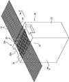
図1~図6は前記実施の形態に係る製造方法及び同方法により製造される電気接続アセンブリを示す。前記電気接続アセンブリは、配線材を構成する複数本の電線10と、当該複数本の電線10を他のコネクタに接続するためのコネクタCNと、を備える。
前記複数本の電線10のそれぞれは、図4に示すような導体12と、当該導体12を被覆する絶縁被覆である絶縁被膜14と、を有する。前記複数本の電線10は、その長手方向と直交する配列方向に間隔をおいて互いに平行に並んだ状態で前記コネクタCNに接続される。
前記コネクタCNは、前記複数の電線10のそれぞれに対応する複数の端子20と、当該複数の端子20をまとめて保持する絶縁ハウジング30と、を備える。
この実施の形態に係る前記複数の端子20のそれぞれは、単一の長尺な金属板により構成された雄型端子であり、図4に示すような被保持部22、電気接触部23及び電線接続部24を有する。前記被保持部22は後述のように前記絶縁ハウジング30に保持される部位である。前記電気接触部23は、この実施の形態では雄型の接触部であって相手方端子の雌型の接触部と嵌合可能な形状を有する。具体的には、前記被保持部22から後述の第1方向に直線状に延びる形状を有する。前記電線接続部24は、前記被保持部22から前記電気接触部23と反対側に突出して前記複数の電線10のうちの対応する電線10に接続される部位である。当該電線接続部24については後述する。
前記絶縁ハウジング30は、合成樹脂等の絶縁材料により成形されたもので、端子保持部32と、フード33と、を一体に有する。
前記端子保持部32は、前記複数の端子20のそれぞれの前記被保持部22を保持する部位であり、この実施の形態ではブロック状をなす。当該端子保持部32は、電線10が前記の配列方向に間隔をおいて並んだ状態で前記複数の端子20の電線接続部24にそれぞれ導通可能に接続されることを可能にするように前記複数の端子20を当該複数の端子20が前記配列方向に並ぶ配列で一括して保持する。
具体的に、当該端子保持部32は、当該端子保持部32を前記端子20が前記第1方向と平行な方向に貫通する状態で当該端子20の被保持部22を保持する。前記第1方向は、前記端子20に前記電線10が接続された状態において当該電線10の長手方向及び配列方向の双方に対して直交する方向であり、図5及び図6に示される姿勢では上方向である。つまり、同姿勢において前記被保持部22は前記端子保持部32の内部において上下方向に延びる姿勢で当該端子保持部32に保持される。当該端子保持部32への当該被保持部22の固定は、当該端子保持部32に設けられた貫通孔への当該被保持部22の圧入により行われてもよいし、接着剤等により行われてもよい。
前記各端子20の電気接触部23は、前記のように被保持部22が前記端子保持部32に保持された状態で当該被保持部22から前記第1方向と反対の方向(図5に示される姿勢では下方向)に延び、当該方向に前記相手方端子の雌型接触部と嵌合する。前記フード33は、前記端子保持部32と一体につながり、前記電気接触部23の軸方向(図5に示される姿勢では上下方向)と直交する方向の外側で当該電気接触部23を囲む筒状をなす。
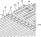
前記各端子20の電線接続部24は、図6に示すような第1突出部26及び第2突出部27を一体に有する。前記第1突出部26は、前記被保持部22から前記第1方向(図6では上方向)に突出する。前記第2突出部27は、前記第1突出部26から前記端子保持部32の表面と平行な方向であって前記配列方向と直交する第2方向(図6では左右方向)に延びる。
前記第2突出部27の表面のうち、前記端子保持部32の上面32aと反対側の面である外側面(図5及び図6では上面)は、導体接続面27aを構成する。当該導体接続面27aは、その上に前記電線10の導体12の特定の部位である接続対象部位が載せられた状態で当該接続対象部位とはんだ付けによって接続されることが可能な面である。この実施の形態に係る導体接続面27aは、前記端子保持部32の上面32aよりも上側の位置で露出した状態で前記端子保持部32の上面32aと平行な方向に延びる。
この実施の形態では、前記端子保持部32の上面32aを基準とした前記各導体接続面27aの高さは、全て同一に設定されている。つまり、当該端子保持部32は、前記各端子20の導体接続面27aが当該端子保持部32の上面32aよりも上側の同一平面上に並ぶように当該端子20を保持する。
また、この実施の形態に係る端子保持部32は、前記複数の端子20の前記導体接続面27aが前記配列方向に間隔をおいて並ぶのに加え、前記複数の端子20のうち前記配列方向に隣接する端子20の導体接続面27aが前記電線10の長手方向に互いに位置をずらして並ぶように、当該複数の端子20の被保持部22を保持する。
この実施の形態に係る絶縁ハウジング30は、前記端子保持部32及び前記フード33により構成されるハウジング本体に加えて一対の固定部34をさらに有する。各固定部34は、前記接続対象部位から当該電線10の長手方向に離れた固定位置で前記電線10と接触可能となるように前記ハウジング本体の表面(この実施の形態では前記端子保持部32の上面32a)から突出するように当該ハウジング本体とつながる。
具体的に、前記各固定部34は、前記電線10の長手方向と平行な方向について、前記各端子20が配設される領域の両外側の位置で前記端子保持部32の上面32aよりも上向きに突出するように当該上面32aとつながる。この実施の形態に係る各固定部34は、前記配列方向に延びる長尺な角柱状をなし、当該固定部34の上面は後述の加熱を受ける被加熱面34aを構成する。
前記固定部34は、前記ハウジング本体を構成する材料(一般には合成樹脂)よりも低い融点をもつ合成樹脂により成形される。具体的に、前記固定部34を構成する材料は、はんだの溶融温度(例えば380°C~400°C)よりも低い融点を有して微細形状への成形が可能な熱可塑性樹脂が好ましい。例えば、PBT(ポリブチレンテレフタレート)樹脂、PPS(ポリフェニレンサルファイド)樹脂、PA6(6ナイロン)樹脂などが好適である。一方、前記ハウジング本体を構成する材料は、前記はんだの溶融温度よりも高い融点を有して成形性及び耐熱性に優れたものが好ましい。例えばLCP(液晶ポリマー)やガラス入り樹脂が好適である。当該固定部34と当該ハウジング本体は例えば2色成形によって一体に成形されることも可能である。
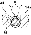
この実施の形態に係る固定部34は、さらに、前記配列方向に並ぶ複数の凹部35を有する。図4及び図6に示すように、前記各凹部35は、前記被加熱面34aから下方に窪む。この実施の形態に係る各凹部35は一定の幅を有して前記電線10の長手方向に延びる凹溝であり、当該凹部35に前記複数の電線10のそれぞれが嵌まり込むことが可能である。当該嵌まり込みによって前記固定部34に対する前記電線10の相対位置、特に前記配列方向についての相対位置、が確実に決められる。
また、前記各凹部35は、当該凹部35に嵌まり込んだ前記電線10の外周面を前記被加熱面34aよりも下側に沈み込ませるだけの深さ寸法を有する。すなわち、この実施の形態に係る各凹部35は、前記各電線10の直径よりも大きな深さ寸法を有する。
次に、前記電気接続アセンブリを製造するための方法について説明する。この方法は次の各工程を含む。
1)電線用意工程及びコネクタ用意工程
上述した複数の電線10及びコネクタCNが予め用意される。さらに、この実施の形態に係る方法では、前記複数の電線10として、各電線10の絶縁被膜14が特定の合成樹脂からなるものが用意される。当該特定の合成樹脂とは、常温で絶縁性を有する一方、後述の接続工程で用いられるはんだの溶融温度(例えば380~400°C)において溶融または分解されることが可能な合成樹脂である。当該特定の合成樹脂としては、ポリウレタン、ポリエステル、ナイロン等が好適である。
上述した複数の電線10及びコネクタCNが予め用意される。さらに、この実施の形態に係る方法では、前記複数の電線10として、各電線10の絶縁被膜14が特定の合成樹脂からなるものが用意される。当該特定の合成樹脂とは、常温で絶縁性を有する一方、後述の接続工程で用いられるはんだの溶融温度(例えば380~400°C)において溶融または分解されることが可能な合成樹脂である。当該特定の合成樹脂としては、ポリウレタン、ポリエステル、ナイロン等が好適である。
前記絶縁被膜14の厚みは、常温状態で絶縁状態を確保しながら前記加熱によって当該絶縁被膜14の除去及び前記導体12の露出を達成できるような厚みに設定されることが好ましい。当該厚みには、例えば通常のエナメル線における絶縁被覆の厚みに近似した寸法が適用されることが可能である。
2)はんだセット工程
前記コネクタCNにおける複数の端子20のそれぞれの導体接続面27aの上に、図6に示すようなはんだSDが予めセットされる。当該セットは、固形状のはんだSDが各導体接続面27aの上に載せられることにより行われてもよいし、ペースト状のはんだSDが各導体接続面27aに塗布されることにより行われてもよい。
前記コネクタCNにおける複数の端子20のそれぞれの導体接続面27aの上に、図6に示すようなはんだSDが予めセットされる。当該セットは、固形状のはんだSDが各導体接続面27aの上に載せられることにより行われてもよいし、ペースト状のはんだSDが各導体接続面27aに塗布されることにより行われてもよい。
3)接続工程及び固定工程
前記複数の電線10が図2に示されるように前記配列方向に互いに間隔をおいて配列された状態を保持しながら当該複数の電線10の長手方向中間領域において設定されている接続対象部位を、当該接続対象部位を前記絶縁被膜14が覆ったままの状態で前記複数の端子20のそれぞれの導体接続面27aに向けて押圧しかつ当該絶縁被膜14を前記はんだSDとともに加熱することにより、当該接続対象部位を覆う前記絶縁被膜14の溶融または分解による前記導体12の表面からの除去と、当該絶縁被膜14の除去により露出する前記導体12と前記導体接続面27aとの前記はんだSDによる電気的接続と、が行われる。
前記複数の電線10が図2に示されるように前記配列方向に互いに間隔をおいて配列された状態を保持しながら当該複数の電線10の長手方向中間領域において設定されている接続対象部位を、当該接続対象部位を前記絶縁被膜14が覆ったままの状態で前記複数の端子20のそれぞれの導体接続面27aに向けて押圧しかつ当該絶縁被膜14を前記はんだSDとともに加熱することにより、当該接続対象部位を覆う前記絶縁被膜14の溶融または分解による前記導体12の表面からの除去と、当該絶縁被膜14の除去により露出する前記導体12と前記導体接続面27aとの前記はんだSDによる電気的接続と、が行われる。
さらに、この実施の形態では、接続工程と同時に、前記はんだSDの溶融のための加熱を利用して各固定部34を溶融させることにより、前記各固定位置において前記絶縁ハウジング30に前記各電線10を固定する固定工程が実行される。以下、その詳細を説明する。
前記複数の電線10の保持は、前記接続対象部位を挟んでその両外側の位置、より好ましくは前記コネクタCNの前後方向(前記第2方向及び電線長手方向と平行な方向)の両端よりも両外側の位置を保持することにより、行われる。当該保持では、前記複数の電線10のそれぞれに適度の張力が与えられながら当該電線10が対応する導体接続面27aの上にセットされる。当該保持は、例えば、前記複数の電線10が巻き付けられるボビンや、前記各電線10をその長手方向及び配列方向の双方に直交する方向の両側から挟み込む挟持具等によって、行われることが可能である。
一方、前記絶縁ハウジング30ではその端子保持部32の上面32aよりも上向きに各固定部34が突出しているので、前記各電線10のセットの際に当該各電線10は前記各固定部34と接触した状態になる。特に、この実施の形態では、前記各固定部34に各電線10に対応した凹部35が形成されているので、前記各電線10は固定位置(この実施の形態では端子20の配設領域の両外側に設定された位置)で前記各凹部35に嵌まり込むことにより前記各固定部34に対する前記各電線10の相対位置が定められる。このことは、絶縁ハウジング30に対する各電線10の相対位置を安定させて製品の品質の向上に寄与する。
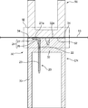
前記導体接続面27aに対する電線10の押圧及び加熱は、図5及び図6に示されるヒータ50を用いて効率的に行われることが、可能である。当該ヒータ50は、加熱面52を構成する平坦な下面を有する。前記各導体接続面27a上に前記はんだSDを介してセットされた前記各電線10に対して前記加熱面52が上から押付けられる。つまり、前記加熱面52と前記各導体接続面27aとの間に当該複数の導体接続面27aにそれぞれ対応する複数の電線10及び前記はんだSDを挟んだ状態で当該加熱面52が前記複数の導体接続面27aに向けて押圧される。これにより、前記導体接続面27aに向けての前記電線10の押圧と、前記ヒータ52による前記はんだSDの加熱による溶融と、前記接続対象部位における前記絶縁被膜14の加熱による当該絶縁被膜14の溶融または分解と、が同時に行われる。当該絶縁被膜14の溶融または分解は、当該絶縁被膜14を前記導体12の表面から除去することを可能にする。
特に、この第1の実施の形態では、前記各導体接続面27aが同一平面上に並ぶように前記絶縁ハウジング30の端子保持部32が前記各端子20を保持している、つまり前記各端子20は前記平面配列端子を構成している、ので、単一の平面状の加熱面52を用いて前記平面配列端子である各端子20の導体接続面27aに前記各電線10の導体12の接続対象部位を同時に接続することが可能である。
さらに、この実施の形態に係る方法の特徴として、前記ヒータ50の加熱面52は前記各電線10への接触と同時に前記各固定部34の被加熱面34aにも接触することが可能な面積を有しており、このことは、当該加熱面52を利用した当該固定部34の加熱による溶融を可能にする。このように溶融した固定部34は、前記電線10の外周面に密着し、その後の冷却(自然冷却または強制冷却)によって固化することにより、前記電線10を強固に保持する。これにより、当該電線10は、その接続対象部位の両外側の位置で前記絶縁ハウジング30に保持される状態となる。より詳しくは、当該電線10は当該絶縁ハウジング30の固定部34を介して端子保持部32に保持される状態となる。この電線10の保持は、各電線10に生ずる張力が前記接続対象部位と導体接続面27aとの接続部位に作用することを有効に抑止し、これにより、簡素な構造で当該接続部位を保護することを可能にする。
しかも、前記絶縁ハウジング30のハウジング本体を構成する材料は前記固定部34よりも高い融点(好ましくははんだの溶融温度よりも高い融点)を有するから、前記加熱によって前記ハウジング本体が変形等するのを回避することが可能である。
この固定工程のためには、図6に示されるように、前記固定部34の被加熱面34aと、前記導体接続面27aの上にはんだSDを介してセットされる電線10の上面とがほぼ同一平面上に並ぶように当該被加熱面34aの高さ(つまり端子保持部32の上面32aからの垂直方向の距離)が設定されることが好ましい。この設定は、前記ヒータ50の下面である加熱面52が前記電線10と前記固定部34の被加熱面34aとにほぼ同時に接触することを可能にする。さらに、当該被加熱面34aよりも前記電線10が沈み込むように前記凹部35の深さ寸法が設定されることが、好ましい。このことは、当該電線10のうち当該凹部35に嵌まり込む部位が前記加熱面52といきなり接触して当該部位における絶縁被膜14が溶融または分解されるのを抑止することを可能にする。
4)切断工程
前記のようにして接続工程が完了した後、電線10の長手方向についてその適当な部位が切断される。この切断は、例えば、一対の切断具により前記電線10をその長手方向及び配列方向と直交する切断方向に挟んでせん断することによって効率的に行われることが可能である。この切断工程は省略されてもよい。
前記のようにして接続工程が完了した後、電線10の長手方向についてその適当な部位が切断される。この切断は、例えば、一対の切断具により前記電線10をその長手方向及び配列方向と直交する切断方向に挟んでせん断することによって効率的に行われることが可能である。この切断工程は省略されてもよい。
本発明は、以上説明した実施の形態に限定されない。本発明は、例えば次のような形態を含む。
A)配線材について
本発明において用いられる配線材は、前記のように複数本の導体12のそれぞれが個別に絶縁被膜14により覆われて電線10を構成するものに限定されない。当該配線材は、前記配列方向に互いに隣り合う導体をそれぞれ覆う絶縁被膜同士が一体につながったもの、例えばフラットケーブルやリボン電線であってもよい。あるいは、絶縁被覆を有しない複数の裸電線により構成されたものでもよい。
本発明において用いられる配線材は、前記のように複数本の導体12のそれぞれが個別に絶縁被膜14により覆われて電線10を構成するものに限定されない。当該配線材は、前記配列方向に互いに隣り合う導体をそれぞれ覆う絶縁被膜同士が一体につながったもの、例えばフラットケーブルやリボン電線であってもよい。あるいは、絶縁被覆を有しない複数の裸電線により構成されたものでもよい。
B)端子について
本発明に係る端子の具体的な形状は限定されない。当該端子は、絶縁ハウジングの外側に露出する導体接続面を有して当該導体接続面に導体の接続対象部位が接続されることが可能なものであればよい。例えば、第1の実施の形態に係る電線接続部24の第1突出部26が大きく突出して第2突出部27全体を端子保持部32の上面32aから外側に離間させてもよい。あるいは、端子の断面積(軸方向に直交する断面の面積)が比較的大きい場合には、当該端子の端面がそのまま導体接続面として用いられてもよい。
本発明に係る端子の具体的な形状は限定されない。当該端子は、絶縁ハウジングの外側に露出する導体接続面を有して当該導体接続面に導体の接続対象部位が接続されることが可能なものであればよい。例えば、第1の実施の形態に係る電線接続部24の第1突出部26が大きく突出して第2突出部27全体を端子保持部32の上面32aから外側に離間させてもよい。あるいは、端子の断面積(軸方向に直交する断面の面積)が比較的大きい場合には、当該端子の端面がそのまま導体接続面として用いられてもよい。
C)接続工程について
前記各実施の形態では、ヒータによる加熱によってはんだの溶融と同時に絶縁被膜14の溶融または分解による導体12の表面からの除去が行われるが、当該絶縁被膜14の除去は加熱の前に予め行われていてもよい。すなわち、複数の電線のそれぞれにおいて設定された接続対象部位における導体を露出させるように絶縁被覆がいわゆる皮剥ぎ処理によって接続工程の前に予め除去され、前記接続工程において前記のように露出した導体と導体接続面とのはんだ付けが直接的に行われてもよい。この場合、前記絶縁被覆を構成する材料は、必ずしもはんだの溶融温度で溶融または分解されるものでなくてもよい。また、配線材が複数の裸電線により構成される場合には前記絶縁被覆の除去を要しないことはいうまでもない。
前記各実施の形態では、ヒータによる加熱によってはんだの溶融と同時に絶縁被膜14の溶融または分解による導体12の表面からの除去が行われるが、当該絶縁被膜14の除去は加熱の前に予め行われていてもよい。すなわち、複数の電線のそれぞれにおいて設定された接続対象部位における導体を露出させるように絶縁被覆がいわゆる皮剥ぎ処理によって接続工程の前に予め除去され、前記接続工程において前記のように露出した導体と導体接続面とのはんだ付けが直接的に行われてもよい。この場合、前記絶縁被覆を構成する材料は、必ずしもはんだの溶融温度で溶融または分解されるものでなくてもよい。また、配線材が複数の裸電線により構成される場合には前記絶縁被覆の除去を要しないことはいうまでもない。
さらに、前記接続のための具体的手段ははんだ付けに限定されない。当該接続は、加熱による他の接続手段、例えば溶接(レーザ溶接、超音波溶接、抵抗溶接等)によって行われてもよい。
D)固定工程について
固定工程における絶縁ハウジングの溶融は、必ずしも接続工程と同時に行われなくてもよい。接続工程が完了した後、例えばはんだが固化した後、に改めて固定部の加熱による固定工程が行われてもよい。逆に、固定工程によって絶縁ハウジングへの配線材の固定が完了した後に改めて接続工程が行われてもよい。また、前記固定工程における固定部の加熱の手段も問わない。前記のようなヒータ50からの伝熱の他、例えば輻射や溶接のための加熱手段によって前記加熱が行われてもよい。
固定工程における絶縁ハウジングの溶融は、必ずしも接続工程と同時に行われなくてもよい。接続工程が完了した後、例えばはんだが固化した後、に改めて固定部の加熱による固定工程が行われてもよい。逆に、固定工程によって絶縁ハウジングへの配線材の固定が完了した後に改めて接続工程が行われてもよい。また、前記固定工程における固定部の加熱の手段も問わない。前記のようなヒータ50からの伝熱の他、例えば輻射や溶接のための加熱手段によって前記加熱が行われてもよい。
E)コネクタについて
コネクタにおける固定部は、導体の接続対象部位から当該導体の長手方向の一方の側にのみ配置されてもよい。換言すれば、図1に示されるようなコネクタCNの場合、当該コネクタCNに含まれる一対の固定部34のうちの一方が省略されてもよい。例えば前記各導体12の接続対象部位が当該導体12の一方の端末の近傍に設定されていて当該一方の配線材の端末に張力が作用するおそれのない場合には、その一方の端末に対応する側の固定部は適宜省略されることが可能である。あるいは、配列方向に並ぶ複数の電線のうち張力が作用するおそれの高い一部の電線についてのみ前記固定工程が行われてもよい。
コネクタにおける固定部は、導体の接続対象部位から当該導体の長手方向の一方の側にのみ配置されてもよい。換言すれば、図1に示されるようなコネクタCNの場合、当該コネクタCNに含まれる一対の固定部34のうちの一方が省略されてもよい。例えば前記各導体12の接続対象部位が当該導体12の一方の端末の近傍に設定されていて当該一方の配線材の端末に張力が作用するおそれのない場合には、その一方の端末に対応する側の固定部は適宜省略されることが可能である。あるいは、配列方向に並ぶ複数の電線のうち張力が作用するおそれの高い一部の電線についてのみ前記固定工程が行われてもよい。
また、ハウジング本体の具体的な形状は特に限定されない。例えばコネクタに含まれる端子が雌型端子である場合、図1等に示されるフード33は必ずしも要しない。
以上のように、複数本の導体を含む配線材とコネクタとを備えた電気接続アセンブリを製造するための方法であって、当該複数本の導体と当該コネクタに含まれる端子との接続部分を簡易な構成で有効に保護することが可能な方法、及び当該方法に好適なコネクタ、が提供される。
提供されるのは、複数の導体を有する配線材と、前記複数の導体のそれぞれに対応する複数の端子及び当該複数の端子を一括して保持する絶縁ハウジングを有するコネクタと、を備え、かつ、前記複数の導体がその長手方向と直交する配列方向に間隔をおいて並んだ状態で前記複数の端子にそれぞれ導通可能に接続される電気接続アセンブリを製造するための方法である。この方法は、前記コネクタとして前記複数の端子のそれぞれが前記絶縁ハウジングの表面から当該絶縁ハウジングの外部に露出する導体接続面を有しかつ当該導体接続面が前記複数の導体同士の前記配列方向の間隔と同等の間隔をおいて当該配列方向に並ぶように当該絶縁ハウジングが当該複数の端子を保持するコネクタを用意するコネクタ用意工程と、前記複数の導体が前記配列方向に互いに間隔をおいて配列された状態を保持しながら当該複数の導体のそれぞれにおいて設定されている接続対象部位とこれに対応する前記導体接続面とを電気的に接続する接続工程と、前記配線材において前記接続対象部位から当該配線材の長手方向に離れた固定位置で当該配線材と前記絶縁ハウジングとを互いに接触させかつ当該固定位置で前記絶縁ハウジングを溶融させてから固化することにより当該絶縁ハウジングに当該配線材を固定する固定工程と、を含む。
当該方法によれば、前記複数の導体とこれに対応する端子の導体接続面とが接続されるのに加え、当該導体の接続対象部位から当該導体の長手方向に離れた固定位置で配線材が前記絶縁ハウジングに固定されることにより、当該絶縁ハウジングの外側において配線材に作用する張力が前記接続部分に伝わることが抑止され、これにより当該接続部分が有効に保護される。しかも、当該絶縁ハウジングへの当該配線材の固定は、固定位置で当該配線材と前記絶縁ハウジングとを互いに接触させかつ当該固定位置で前記絶縁ハウジングを溶融させてから固化することにより行われるので、大掛かりな設備をコネクタに付加することなく前記絶縁ハウジングを利用した簡素な構成で前記接続部分の保護を達成することができる。
さらに、前記固定工程における前記絶縁ハウジングの溶融は、前記導体と前記導体接続面との接続のための加熱を利用して行われることも可能である。例えば、当該接続のためのはんだ付けを行うためのヒータを用いて当該はんだ付けと同時に前記溶融を行うことも、可能である。つまり、前記接続工程と前記固定工程とを共通のヒータを用いて同時に行うことも可能である。このことは、電気接続アセンブリの製造効率を飛躍的に向上させる。
前記コネクタとしては、前記絶縁ハウジングが前記複数の端子を保持する部分を含むハウジング本体と当該ハウジング本体を構成する材料よりも低い融点をもつ合成樹脂からなる固定部とを有しかつ当該固定部が前記固定位置で前記配線材と接触可能となるように前記ハウジング本体の表面から突出するように当該ハウジング本体とつながるコネクタが用意されることが、好ましい。この場合、前記固定工程では、前記固定位置で前記配線材と前記固定部とが互いに接触した状態で当該固定部を溶融させてから固化することにより当該固定部に当該配線材を固定することが可能である。しかも、前記絶縁ハウジングのハウジング本体を構成する材料は前記固定部よりも高い融点を有するから、前記固定部の加熱によって前記ハウジング本体が変形等するのを回避することが可能である。
また、前記方法に適したコネクタが提供される。当該コネクタは、複数の導体を含む配線材と接続されることにより、電気接続アセンブリを構成するものであって、前記複数の導体のそれぞれに対応する複数の端子と、前記複数の導体がその長手方向と直交する配列方向に並んだ状態で前記複数の端子にそれぞれ導通可能に接続されることを可能にする配列で前記複数の端子を一括して保持する絶縁ハウジングと、を備える。前記複数の端子のそれぞれは、前記絶縁ハウジングの表面から当該絶縁ハウジングの外部に露出する面であって前記導体のそれぞれに設定された接続対象部位と接続可能な導体接続面を有する。前記絶縁ハウジングは、前記複数の端子を保持する部分を含むハウジング本体と、当該ハウジング本体を構成する材料よりも低い融点をもつ合成樹脂からなる固定部と、を有する。当該固定部は、前記接続対象部位から前記配線材の長手方向に離れた固定位置で前記配線材と接触可能となるように前記ハウジング本体の表面から突出するように当該ハウジング本体とつながる。
前記コネクタの前記固定部は、前記固定位置において前記配線材が嵌まり込むことが可能な凹部を有してその嵌まり込みによって当該固定部に対する前記配線材の相対位置を決める形状を有することが、好ましい。当該固定部の凹部は、当該固定部に対する配線材の相対位置、つまり、絶縁ハウジングに対して配線材が固定される固定位置、を安定させ、これにより電気接続アセンブリの品質の向上を可能にする。
前記凹部は、当該凹部に前記配線材が嵌まり込んだ状態で当該配線材の表面を前記固定部の表面よりも沈み込ませるだけの深さ寸法を有することが、好ましい。このことは、前記固定部を加熱するためのヒータを前記凹部に嵌まり込んだ配線材に接触させずに前記固定部の表面に接触させることを容易にする。
また本発明によれば、複数の導体を含む配線材と、前記コネクタと、を備えた電気接続アセンブリであって、前記複数の導体がその長手方向と直交する配列方向に並んだ状態で当該複数の導体のそれぞれの接続対象部位が前記コネクタにおける前記複数の端子の前記導体接続面のそれぞれに接続され、かつ、前記接続対象部位から前記配線材の長手方向に離れた固定位置で前記配線材が前記固定部に固定されているものが、提供される。この電気接続アセンブリによれば、前記絶縁ハウジングの一部である固定部を用いるだけの簡素な構成で、前記配線材の各導体の接続対象部位と前記端子の導体接続面との接続部分が有効に保護される。
Claims (8)
- 複数の導体を有する配線材と、前記複数の導体のそれぞれに対応する複数の端子及び当該複数の端子を一括して保持する絶縁ハウジングを有するコネクタと、を備え、かつ、前記複数の導体がその長手方向と直交する配列方向に間隔をおいて並んだ状態で前記複数の端子にそれぞれ導通可能に接続される電気接続アセンブリを製造するための方法であって、
前記コネクタとして前記複数の端子のそれぞれが前記絶縁ハウジングの表面から当該絶縁ハウジングの外部に露出する導体接続面を有しかつ当該導体接続面が前記複数の導体同士の前記配列方向の間隔と同等の間隔をおいて当該配列方向に並ぶように当該絶縁ハウジングが当該複数の端子を保持するコネクタを用意するコネクタ用意工程と、
前記複数の導体が前記配列方向に互いに間隔をおいて配列された状態を保持しながら当該複数の導体のそれぞれにおいて設定されている接続対象部位とこれに対応する前記導体接続面とを電気的に接続する接続工程と、
前記配線材において前記接続対象部位から当該配線材の長手方向に離れた固定位置で当該配線材と前記絶縁ハウジングとを互いに接触させかつ当該固定位置で前記絶縁ハウジングを溶融させてから固化することにより当該絶縁ハウジングに当該配線材を固定する固定工程と、を含む、電気接続アセンブリの製造方法。 - 請求項1記載の電気接続アセンブリの製造方法であって、前記固定工程における前記絶縁ハウジングの溶融は、前記導体と前記導体接続面との接続のための加熱を利用して行われる、電気接続アセンブリの製造方法。
- 請求項2記載の電気接続アセンブリの製造方法であって、前記固定工程における前記絶縁ハウジングの溶融は、前記はんだ付けを行うためのヒータを用いて当該はんだ付けと同時に行われる、電気接続アセンブリの製造方法。
- 請求項1~3のいずれかに記載の電気接続アセンブリの製造方法であって、前記コネクタ用意工程では、前記コネクタとして、前記絶縁ハウジングが前記複数の端子を保持する部分を含むハウジング本体と当該ハウジング本体を構成する材料よりも低い融点をもつ合成樹脂からなる固定部とを有しかつ当該固定部が前記固定位置で前記配線材と接触可能となるように前記ハウジング本体の表面から突出するように当該ハウジング本体とつながるコネクタが用意され、前記固定工程は、前記固定位置で前記配線材と前記固定部とが互いに接触した状態で当該固定部を溶融させてから固化することにより当該固定部に当該配線材を固定することを含む、電気接続アセンブリの製造方法。
- 複数の導体を有する配線材と接続されることにより、電気接続アセンブリを構成するコネクタであって、
前記複数の導体のそれぞれに対応する複数の端子と、
前記複数の導体がその長手方向と直交する配列方向に並んだ状態で前記複数の端子にそれぞれ導通可能に接続されることを可能にする配列で前記複数の端子を一括して保持する絶縁ハウジングと、を備え、
前記複数の端子のそれぞれは、前記絶縁ハウジングの表面から当該絶縁ハウジングの外部に露出する面であって前記導体のそれぞれに設定された接続対象部位と接続可能な導体接続面を有し、
前記絶縁ハウジングは、前記複数の端子を保持する部分を含むハウジング本体と、当該ハウジング本体を構成する材料よりも低い融点をもつ合成樹脂からなる固定部と、を有し、当該固定部は、前記接続対象部位から前記配線材の長手方向に離れた固定位置で前記配線材と接触可能となるように前記ハウジング本体の表面から突出するように当該ハウジング本体とつながる、コネクタ。 - 請求項5記載のコネクタであって、前記固定部は、前記固定位置において前記配線材が嵌まり込むことが可能な凹部を有してその嵌まり込みによって当該固定部に対する前記配線材の相対位置を決める形状を有する、コネクタ。
- 請求項6記載のコネクタであって、前記凹部は、当該凹部に前記配線材が嵌まり込んだ状態で当該配線材の表面を前記固定部の表面よりも沈み込ませるだけの深さ寸法を有する、コネクタ。
- 電気接続アセンブリであって、
複数の導体を含む配線材と、
請求項5~7のいずれかに記載のコネクタと、を備え、
前記複数の導体がその長手方向と直交する配列方向に並んだ状態で当該複数の導体のそれぞれの接続対象部位が前記コネクタにおける前記複数の端子の前記導体接続面のそれぞれに接続され、かつ、前記接続対象部位から前記配線材の長手方向に離れた固定位置で前記固定部に固定されている、電気接続アセンブリ。
Priority Applications (2)
| Application Number | Priority Date | Filing Date | Title |
|---|---|---|---|
| CN201780042526.8A CN109478751B (zh) | 2016-07-12 | 2017-06-22 | 电气连接组件的制造方法 |
| US16/316,258 US10804622B2 (en) | 2016-07-12 | 2017-06-22 | Method for manufacturing electrical connection assembly |
Applications Claiming Priority (2)
| Application Number | Priority Date | Filing Date | Title |
|---|---|---|---|
| JP2016-137285 | 2016-07-12 | ||
| JP2016137285A JP6638584B2 (ja) | 2016-07-12 | 2016-07-12 | 電気接続アセンブリの製造方法 |
Publications (1)
| Publication Number | Publication Date |
|---|---|
| WO2018012238A1 true WO2018012238A1 (ja) | 2018-01-18 |
Family
ID=60951801
Family Applications (1)
| Application Number | Title | Priority Date | Filing Date |
|---|---|---|---|
| PCT/JP2017/022977 Ceased WO2018012238A1 (ja) | 2016-07-12 | 2017-06-22 | 電気接続アセンブリの製造方法 |
Country Status (4)
| Country | Link |
|---|---|
| US (1) | US10804622B2 (ja) |
| JP (1) | JP6638584B2 (ja) |
| CN (1) | CN109478751B (ja) |
| WO (1) | WO2018012238A1 (ja) |
Families Citing this family (2)
| Publication number | Priority date | Publication date | Assignee | Title |
|---|---|---|---|---|
| KR102580241B1 (ko) | 2020-10-13 | 2023-09-19 | 삼성에스디아이 주식회사 | 배터리 팩 |
| CN115425489A (zh) * | 2022-09-30 | 2022-12-02 | 深圳市一航电动科技有限公司 | 一种标准化充电枪的加工工艺 |
Citations (5)
| Publication number | Priority date | Publication date | Assignee | Title |
|---|---|---|---|---|
| JPS6436987U (ja) * | 1987-08-31 | 1989-03-06 | ||
| JP2000058170A (ja) * | 1998-08-03 | 2000-02-25 | Furukawa Electric Co Ltd:The | 扁平電線と接続端子の接続構造及び接続方法 |
| JP2001176603A (ja) * | 1999-12-15 | 2001-06-29 | Sumitomo Wiring Syst Ltd | コネクタ |
| JP3083026U (ja) * | 2001-06-28 | 2002-01-18 | モルデック株式会社 | コネクタ |
| JP3183252U (ja) * | 2012-08-10 | 2013-05-09 | 株式会社バッファロー | ロッキングアームの折れにくいrj45、rj11コネクタ |
Family Cites Families (12)
| Publication number | Priority date | Publication date | Assignee | Title |
|---|---|---|---|---|
| US4083902A (en) * | 1977-01-10 | 1978-04-11 | Raychem Corporation | Method of sealing a connector |
| US4601036A (en) | 1982-09-30 | 1986-07-15 | Honeywell Inc. | Rapidly tunable laser |
| JPS6436987A (en) | 1987-07-31 | 1989-02-07 | Nippon Mining Co | Air compressor |
| DE19510341A1 (de) * | 1994-12-24 | 1996-06-27 | Alcatel Kabel Ag | Verfahren zur zugentlasteten Festlegung einer elektrischen Leitung |
| JP3311620B2 (ja) * | 1996-12-24 | 2002-08-05 | 矢崎総業株式会社 | 電線接続構造 |
| JP2008510621A (ja) * | 2004-08-25 | 2008-04-10 | 松下電器産業株式会社 | 半田組成物及び半田接合方法並びに半田接合構造 |
| JP4654865B2 (ja) * | 2005-09-30 | 2011-03-23 | パナソニック株式会社 | 電子部品実装方法 |
| JP2008270014A (ja) * | 2007-04-23 | 2008-11-06 | Molex Inc | フローティングコネクタ |
| JP2010146939A (ja) | 2008-12-22 | 2010-07-01 | Sumitomo Electric Ind Ltd | フラットケーブルの半田接続方法 |
| TWM371317U (en) * | 2009-08-10 | 2009-12-21 | Ant Prec Industry Co Ltd | SATA electrical connector and assembly thereof |
| JP5794671B2 (ja) * | 2011-04-28 | 2015-10-14 | 日本航空電子工業株式会社 | コネクタ |
| US9276330B2 (en) * | 2014-01-24 | 2016-03-01 | Foxconn Interconnect Technology Limited | Cable connector assembly having a conductive element for connecting grounding layers of the cable together |
-
2016
- 2016-07-12 JP JP2016137285A patent/JP6638584B2/ja not_active Expired - Fee Related
-
2017
- 2017-06-22 WO PCT/JP2017/022977 patent/WO2018012238A1/ja not_active Ceased
- 2017-06-22 US US16/316,258 patent/US10804622B2/en not_active Expired - Fee Related
- 2017-06-22 CN CN201780042526.8A patent/CN109478751B/zh not_active Expired - Fee Related
Patent Citations (5)
| Publication number | Priority date | Publication date | Assignee | Title |
|---|---|---|---|---|
| JPS6436987U (ja) * | 1987-08-31 | 1989-03-06 | ||
| JP2000058170A (ja) * | 1998-08-03 | 2000-02-25 | Furukawa Electric Co Ltd:The | 扁平電線と接続端子の接続構造及び接続方法 |
| JP2001176603A (ja) * | 1999-12-15 | 2001-06-29 | Sumitomo Wiring Syst Ltd | コネクタ |
| JP3083026U (ja) * | 2001-06-28 | 2002-01-18 | モルデック株式会社 | コネクタ |
| JP3183252U (ja) * | 2012-08-10 | 2013-05-09 | 株式会社バッファロー | ロッキングアームの折れにくいrj45、rj11コネクタ |
Also Published As
| Publication number | Publication date |
|---|---|
| JP2018010746A (ja) | 2018-01-18 |
| CN109478751A (zh) | 2019-03-15 |
| CN109478751B (zh) | 2020-12-11 |
| JP6638584B2 (ja) | 2020-01-29 |
| US20190305439A1 (en) | 2019-10-03 |
| US10804622B2 (en) | 2020-10-13 |
Similar Documents
| Publication | Publication Date | Title |
|---|---|---|
| JPH11312568A (ja) | ステアリング用電気的接続装置における電線とフラットケーブルの接続コネクタ | |
| EP2940799B1 (en) | Terminal connecting structure and terminal connecting method | |
| CN109148802B (zh) | 母线以及具备该母线的连接模块 | |
| CN105390905B (zh) | 覆皮电线的接合方法 | |
| US10651573B2 (en) | Connector with terminals that are connectable to parallel conductors of a wiring material to form an electrical connection assembly | |
| US10566705B2 (en) | Method for manufacturing electrical connection assembly | |
| CN110226262B (zh) | 电连接组件及其制造方法 | |
| JP6638584B2 (ja) | 電気接続アセンブリの製造方法 | |
| JPH11329531A (ja) | フラットケーブル用接続コネクタ | |
| JP6776918B2 (ja) | コネクタ及びこれを備えた電気接続アセンブリの製造方法 | |
| JP6614051B2 (ja) | 電気接続アセンブリの製造方法 | |
| EP3916920B1 (en) | Terminal connecting structure | |
| WO2018012237A1 (ja) | コネクタ及びこれを備えた電気接続アセンブリ | |
| JP2023170102A (ja) | 電線溶接方法 | |
| JP2010157396A (ja) | コネクタ及びその製造方法 | |
| JP2007172900A (ja) | 同軸ケーブル用電気コネクタ |
Legal Events
| Date | Code | Title | Description |
|---|---|---|---|
| 121 | Ep: the epo has been informed by wipo that ep was designated in this application |
Ref document number: 17827368 Country of ref document: EP Kind code of ref document: A1 |
|
| NENP | Non-entry into the national phase |
Ref country code: DE |
|
| 122 | Ep: pct application non-entry in european phase |
Ref document number: 17827368 Country of ref document: EP Kind code of ref document: A1 |