WO2018008469A1 - 蓄電装置、蓄電システム、並びに、電源システム - Google Patents
蓄電装置、蓄電システム、並びに、電源システム Download PDFInfo
- Publication number
- WO2018008469A1 WO2018008469A1 PCT/JP2017/023552 JP2017023552W WO2018008469A1 WO 2018008469 A1 WO2018008469 A1 WO 2018008469A1 JP 2017023552 W JP2017023552 W JP 2017023552W WO 2018008469 A1 WO2018008469 A1 WO 2018008469A1
- Authority
- WO
- WIPO (PCT)
- Prior art keywords
- capacity
- full charge
- power
- voltage
- storage device
- Prior art date
Links
Images


Classifications
-
- G—PHYSICS
- G01—MEASURING; TESTING
- G01R—MEASURING ELECTRIC VARIABLES; MEASURING MAGNETIC VARIABLES
- G01R31/00—Arrangements for testing electric properties; Arrangements for locating electric faults; Arrangements for electrical testing characterised by what is being tested not provided for elsewhere
- G01R31/36—Arrangements for testing, measuring or monitoring the electrical condition of accumulators or electric batteries, e.g. capacity or state of charge [SoC]
- G01R31/374—Arrangements for testing, measuring or monitoring the electrical condition of accumulators or electric batteries, e.g. capacity or state of charge [SoC] with means for correcting the measurement for temperature or ageing
-
- G—PHYSICS
- G01—MEASURING; TESTING
- G01R—MEASURING ELECTRIC VARIABLES; MEASURING MAGNETIC VARIABLES
- G01R31/00—Arrangements for testing electric properties; Arrangements for locating electric faults; Arrangements for electrical testing characterised by what is being tested not provided for elsewhere
- G01R31/36—Arrangements for testing, measuring or monitoring the electrical condition of accumulators or electric batteries, e.g. capacity or state of charge [SoC]
- G01R31/364—Battery terminal connectors with integrated measuring arrangements
-
- G—PHYSICS
- G01—MEASURING; TESTING
- G01R—MEASURING ELECTRIC VARIABLES; MEASURING MAGNETIC VARIABLES
- G01R31/00—Arrangements for testing electric properties; Arrangements for locating electric faults; Arrangements for electrical testing characterised by what is being tested not provided for elsewhere
- G01R31/36—Arrangements for testing, measuring or monitoring the electrical condition of accumulators or electric batteries, e.g. capacity or state of charge [SoC]
- G01R31/382—Arrangements for monitoring battery or accumulator variables, e.g. SoC
- G01R31/3828—Arrangements for monitoring battery or accumulator variables, e.g. SoC using current integration
-
- G—PHYSICS
- G01—MEASURING; TESTING
- G01R—MEASURING ELECTRIC VARIABLES; MEASURING MAGNETIC VARIABLES
- G01R31/00—Arrangements for testing electric properties; Arrangements for locating electric faults; Arrangements for electrical testing characterised by what is being tested not provided for elsewhere
- G01R31/36—Arrangements for testing, measuring or monitoring the electrical condition of accumulators or electric batteries, e.g. capacity or state of charge [SoC]
- G01R31/382—Arrangements for monitoring battery or accumulator variables, e.g. SoC
- G01R31/3842—Arrangements for monitoring battery or accumulator variables, e.g. SoC combining voltage and current measurements
-
- G—PHYSICS
- G01—MEASURING; TESTING
- G01R—MEASURING ELECTRIC VARIABLES; MEASURING MAGNETIC VARIABLES
- G01R31/00—Arrangements for testing electric properties; Arrangements for locating electric faults; Arrangements for electrical testing characterised by what is being tested not provided for elsewhere
- G01R31/36—Arrangements for testing, measuring or monitoring the electrical condition of accumulators or electric batteries, e.g. capacity or state of charge [SoC]
- G01R31/392—Determining battery ageing or deterioration, e.g. state of health
-
- H—ELECTRICITY
- H01—ELECTRIC ELEMENTS
- H01M—PROCESSES OR MEANS, e.g. BATTERIES, FOR THE DIRECT CONVERSION OF CHEMICAL ENERGY INTO ELECTRICAL ENERGY
- H01M10/00—Secondary cells; Manufacture thereof
- H01M10/42—Methods or arrangements for servicing or maintenance of secondary cells or secondary half-cells
- H01M10/425—Structural combination with electronic components, e.g. electronic circuits integrated to the outside of the casing
-
- H—ELECTRICITY
- H01—ELECTRIC ELEMENTS
- H01M—PROCESSES OR MEANS, e.g. BATTERIES, FOR THE DIRECT CONVERSION OF CHEMICAL ENERGY INTO ELECTRICAL ENERGY
- H01M10/00—Secondary cells; Manufacture thereof
- H01M10/42—Methods or arrangements for servicing or maintenance of secondary cells or secondary half-cells
- H01M10/44—Methods for charging or discharging
- H01M10/448—End of discharge regulating measures
-
- H—ELECTRICITY
- H01—ELECTRIC ELEMENTS
- H01M—PROCESSES OR MEANS, e.g. BATTERIES, FOR THE DIRECT CONVERSION OF CHEMICAL ENERGY INTO ELECTRICAL ENERGY
- H01M10/00—Secondary cells; Manufacture thereof
- H01M10/42—Methods or arrangements for servicing or maintenance of secondary cells or secondary half-cells
- H01M10/48—Accumulators combined with arrangements for measuring, testing or indicating the condition of cells, e.g. the level or density of the electrolyte
- H01M10/482—Accumulators combined with arrangements for measuring, testing or indicating the condition of cells, e.g. the level or density of the electrolyte for several batteries or cells simultaneously or sequentially
-
- H—ELECTRICITY
- H02—GENERATION; CONVERSION OR DISTRIBUTION OF ELECTRIC POWER
- H02J—CIRCUIT ARRANGEMENTS OR SYSTEMS FOR SUPPLYING OR DISTRIBUTING ELECTRIC POWER; SYSTEMS FOR STORING ELECTRIC ENERGY
- H02J3/00—Circuit arrangements for ac mains or ac distribution networks
- H02J3/28—Arrangements for balancing of the load in a network by storage of energy
- H02J3/32—Arrangements for balancing of the load in a network by storage of energy using batteries with converting means
-
- H—ELECTRICITY
- H02—GENERATION; CONVERSION OR DISTRIBUTION OF ELECTRIC POWER
- H02J—CIRCUIT ARRANGEMENTS OR SYSTEMS FOR SUPPLYING OR DISTRIBUTING ELECTRIC POWER; SYSTEMS FOR STORING ELECTRIC ENERGY
- H02J3/00—Circuit arrangements for ac mains or ac distribution networks
- H02J3/38—Arrangements for parallely feeding a single network by two or more generators, converters or transformers
-
- H—ELECTRICITY
- H02—GENERATION; CONVERSION OR DISTRIBUTION OF ELECTRIC POWER
- H02J—CIRCUIT ARRANGEMENTS OR SYSTEMS FOR SUPPLYING OR DISTRIBUTING ELECTRIC POWER; SYSTEMS FOR STORING ELECTRIC ENERGY
- H02J7/00—Circuit arrangements for charging or depolarising batteries or for supplying loads from batteries
- H02J7/0013—Circuit arrangements for charging or depolarising batteries or for supplying loads from batteries acting upon several batteries simultaneously or sequentially
-
- G—PHYSICS
- G01—MEASURING; TESTING
- G01R—MEASURING ELECTRIC VARIABLES; MEASURING MAGNETIC VARIABLES
- G01R31/00—Arrangements for testing electric properties; Arrangements for locating electric faults; Arrangements for electrical testing characterised by what is being tested not provided for elsewhere
- G01R31/36—Arrangements for testing, measuring or monitoring the electrical condition of accumulators or electric batteries, e.g. capacity or state of charge [SoC]
- G01R31/396—Acquisition or processing of data for testing or for monitoring individual cells or groups of cells within a battery
-
- Y—GENERAL TAGGING OF NEW TECHNOLOGICAL DEVELOPMENTS; GENERAL TAGGING OF CROSS-SECTIONAL TECHNOLOGIES SPANNING OVER SEVERAL SECTIONS OF THE IPC; TECHNICAL SUBJECTS COVERED BY FORMER USPC CROSS-REFERENCE ART COLLECTIONS [XRACs] AND DIGESTS
- Y02—TECHNOLOGIES OR APPLICATIONS FOR MITIGATION OR ADAPTATION AGAINST CLIMATE CHANGE
- Y02E—REDUCTION OF GREENHOUSE GAS [GHG] EMISSIONS, RELATED TO ENERGY GENERATION, TRANSMISSION OR DISTRIBUTION
- Y02E60/00—Enabling technologies; Technologies with a potential or indirect contribution to GHG emissions mitigation
- Y02E60/10—Energy storage using batteries
Definitions
- the present invention relates to a power storage device, a power storage system, and a power supply system.
- the present invention particularly relates to a stationary power storage device.
- a power supply system includes a power generation device and a power storage device in addition to a system power supply and can supply self-generated power to an external load.
- This power supply system is parallel to the system power supply, and generally charges the power storage device with power supplied from the system power supply at night when the power charge is low. Supply to external load. In this way, the electricity charge can be reduced.
- some power storage devices that store power include a built-in secondary battery group in which a plurality of secondary batteries are connected in series. Such a power storage device includes a plurality of secondary batteries connected in series. As a result, the voltage is increased, and more power can be charged and discharged.
- the secondary battery built in the power storage device has a reduced battery capacity when the constituent material of the secondary battery deteriorates due to long-term use, and the actual full charge capacity and the full charge capacity at the time of shipment are reduced. Will cause a difference. For this reason, if the operation continues with the full charge capacity setting at the time of shipment, charging and discharging are performed in accordance with the actual full charge capacity, and overdischarge and overcharge may occur in some cases. When overdischarge or overcharge occurs, there is a problem in that deterioration of the constituent material of the secondary battery is promoted and the life of the secondary battery is shortened.
- the secondary batteries in the secondary battery group are manufactured at the same time. Since individual differences occur, there is a problem that overdischarge and overcharge are likely to occur in secondary batteries with a small capacity in the secondary battery group.
- an object of the present invention is to develop a power storage device, a power storage system, and a power supply system that can set a full charge capacity according to an actual full charge capacity.
- One aspect of the present invention for solving the above-described problems includes a battery unit and a control unit that controls charging / discharging of the battery unit, and the battery unit has a preset capacity set from a full charge capacity.
- the controller can execute a full charge capacity correction mode, and the full charge capacity correction mode is preset when the battery part is discharged from the full charge capacity to the set capacity.
- a remaining capacity calculation operation for calculating a remaining capacity corresponding to the first voltage in a state of being discharged to the set capacity based on the correlation between the voltage of the battery unit and the battery capacity, and the set capacity from the full charge capacity And calculating a current consumption of the battery unit between the fully charged capacity and the set capacity, and performing a consumed capacity calculating operation to calculate a sum of the remaining capacity and the consumed capacity.
- Fully charged A power storage device to be set as an amount.
- the “current amount” here includes not only positive but also negative. For example, if the amount of current due to discharging is + i [A], the amount of current due to charging is -i [A].
- the “full charge capacity” here is a charge capacity in a state that is regarded as a full charge state according to a predetermined standard.
- the “first voltage in the set capacity” refers to the voltage of the entire battery part or a part in the set capacity. That is, the “first voltage in the set capacity” refers to the voltage of the entire battery unit when the battery unit is configured by a single battery, and when the battery unit is configured by a plurality of batteries, It includes not only the voltage of the entire battery unit, but also the individual voltage or group of voltages of each battery.
- the remaining capacity calculation operation for calculating the remaining capacity and the consumption capacity calculation operation for calculating the consumption capacity are performed on the condition that the battery unit is discharged from the full charge capacity to the set capacity.
- the calculation is performed separately, and the calculation results of the remaining capacity calculation operation and the consumed capacity calculation operation are added to newly set as the actual full charge capacity. That is, the remaining capacity as the actual charging capacity is calculated using the correlation between the battery voltage and the battery capacity set in advance in the remaining capacity calculating operation, and the change in the battery section is monitored in the consumed capacity calculating operation.
- the consumed capacity is calculated based on a standard different from the remaining capacity calculating operation, and the full charge capacity is newly set. Therefore, the full charge capacity according to the capacity reduction of the battery part due to the deterioration of the battery part can be accurately set, and the control associated therewith can be performed, so that overvoltage and overcharge can be prevented.
- a preferable aspect is that the full charge capacity correction mode is performed when the battery unit only discharges from the full charge capacity to the set capacity.
- the full charge capacity correction mode is performed when only discharging is performed from the full charge capacity to the set capacity, and the actual full charge capacity can be set in a state where the influence of the capacity change due to charging is excluded.
- the full charge capacity can be set more accurately.
- control unit includes voltage detection means for detecting the voltage of the battery unit, and the current capacity in the battery unit is substantially zero and the set capacity is maintained. It is to acquire the voltage of the battery unit after a predetermined time has passed since the arrival as the first voltage.
- “to make the current balance in the battery part substantially zero” means to limit the charging current to the battery part and the discharging current from the battery part to a negligible level.
- the charging current to the battery and the discharge current from the battery are limited to 0.01 C or less.
- “1C” refers to a current value at which discharge is terminated by constant current discharge for one hour. That is, “0.01 C” is a current value at which the discharge is terminated after 100 hours of constant current discharge.
- the first voltage is measured after a predetermined time has elapsed in a state where the current balance in the battery unit is substantially zero. Therefore, since a pseudo open circuit potential (hereinafter also referred to as OCV) in the set capacity in a stable state can be acquired, the measured value is less likely to fluctuate and the actual charge capacity can be easily calculated.
- OCV pseudo open circuit potential
- the battery unit includes a plurality of secondary battery groups connected in series, the voltage detection unit can detect the voltage of each secondary battery group, and the control unit The minimum voltage of each secondary battery group after a predetermined time has elapsed since reaching the set capacity in a state where the current balance in the battery unit is substantially zero and the set capacity is maintained.
- the remaining capacity calculation operation is to calculate the remaining capacity based on the first voltage and the minimum voltage.
- the secondary battery group in the battery unit since the remaining capacity is calculated based on the minimum voltage of the secondary battery group in the battery unit in addition to the first voltage in the pseudo open circuit state, the secondary battery group in the battery unit The full charge capacity can be set based on the minimum voltage.
- the battery unit includes a plurality of secondary battery groups connected in series, the control unit repeatedly executes the full charge capacity correction mode, and the full charge capacity correction mode is This is to be performed when a predetermined period has elapsed from the setting of the past full charge capacity and only discharging is performed from the full charge capacity to the set capacity.
- the full charge capacity correction mode is executed when the interval for performing the full charge capacity correction mode is a predetermined period and only the discharge is performed. It is hard to interfere with driving operation.
- the consumption capacity calculation operation is to calculate the consumption capacity by integrating the amount of current of the battery unit from the full charge capacity to the set capacity.
- One aspect of the present invention is a power storage system that includes the power storage device described above and a power conversion device that converts AC power and DC power, and is electrically connectable to the power generation device.
- the power storage system is capable of charging generated power to a power storage device.
- the electricity bill paid by the user can be reduced.
- the power conversion device can be electrically connected to a system power supply, and can convert AC power supplied from the system power supply into DC power and charge the power storage device.
- the AC power supplied from the system power supply can be converted into DC power and charged to the power storage device.
- the power storage device is charged in a time zone where the electricity rate is low and the electricity rate is high.
- the electricity stored in can be used. Therefore, the electricity bill paid by the user can be reduced.
- One aspect of the present invention includes the above-described power storage device and a display device capable of acquiring and displaying information on the power of the power storage device, and the control unit substantially reduces a current balance in the battery unit.
- the control unit substantially reduces a current balance in the battery unit.
- the power supply system does not update information on the power of the power storage device for a predetermined period after the battery unit reaches the set capacity.
- “Information about power” here means voltage, current, power, charge capacity, and the like.
- the information processing apparatus includes a display device that can acquire information related to the power of the power storage device and display the information. Therefore, the user can visually recognize information related to the power of the power storage device, and can grasp the current status of the power storage device.
- a display device that can acquire information related to the power of the power storage device and display the information. Therefore, the user can visually recognize information related to the power of the power storage device, and can grasp the current status of the power storage device.
- the display device does not update the information regarding the power of the power storage device for a predetermined period after the battery unit reaches the set capacity.
- the information displayed on the screen is viewed, it can be prevented that a malfunction or the like has occurred.
- the full charge capacity can be set according to the actual full charge capacity.
- FIG. 2 It is a block diagram showing the power supply system of 1st Embodiment of this invention. It is a block diagram of the electrical storage apparatus of FIG. 2 is a flowchart until a transition from a normal operation mode of the power storage device of FIG. 1 to a full charge capacity correction mode is performed. 4 is a flowchart of a full charge capacity correction mode of the power storage device of FIG. 3. It is a graph which shows the correlation of the charging rate of the secondary battery group of an electrical storage apparatus of FIG. 3, and an open circuit electric potential. 4 is a graph showing a typical voltage transition in the full charge capacity correction mode of the power storage device of FIG. 3.
- the power supply system 1 is a power supply system that is provided mainly in a building such as a house or a building and constitutes a power supply for an external load 100 such as an appliance. That is, the power supply system 1 is a stationary power supply system that is used while being fixed at a desired position. As shown in FIG. 1, the power supply system 1 includes a power generation device 2, a power supply control device 3, a display device (not shown), and a power storage system 5. In the power supply system 1, an external load 100 and a system power supply 101 are connected to the power supply control device 3, and power supplied from the system power supply 101, which is a commercial power supply supplied from an electric power company or the like, is supplied to the external load 100. is there.
- the power generation device 2 is a power generation device such as a solar cell module or a fuel cell module, and is a device that serves as a power source other than the system power supply 101.
- the power supply control device 3 is a device that can switch the power supply to the external load 100 between the system power supply 101 and the power storage system 5.
- the display device is a device that displays information about the power of the power generation device 2 and the power of the power storage device 8, and can display the current-voltage curves of the power generation device 2 and the power storage device 8.
- the power storage system 5 includes a power conversion device 7 and a power storage device 8.
- the power converter 7 is a so-called power conditioner, and can convert AC power into DC power. That is, the power conversion device 7 is electrically connected to the power generation device 2 to convert the DC power generated by the power generation device 2 into AC power and supply it to the power supply control device 3 or to the system power supply 101 electrically. By connecting, AC power fed from the system power supply 101 can be converted into DC power and supplied to the power storage device 8.
- the power storage device 8 temporarily stores the power generated by the power generation device 2 or the power supplied from the system power supply 101. As shown in FIG. 2, the power storage device 8 includes a secondary battery unit 10 (battery unit) and a control unit 9 (control unit).
- the secondary battery unit 10 a plurality of secondary battery groups 20a to 20e are electrically connected in series. As shown in FIG. 2, the secondary battery unit 10 of the present embodiment is composed of five secondary battery groups 20a to 20e. The secondary battery groups 20a to 20e are obtained by electrically connecting a plurality of secondary batteries in series.
- the control unit 9 controls charging / discharging of the secondary battery unit 10, and includes a plurality of voltage detection means 11a to 11e (voltage information detection means) and a current detection means 12 (current information detection means) as main components. ), A charge / discharge control unit 15, and a switching unit 16.
- the voltage detectors 11a to 11e are members corresponding to the secondary battery groups 20a to 20e, and are members for detecting the voltages of the secondary battery groups 20a to 20e. Can be detected independently of each other.
- the current detection means 12 is a device that detects the charge / discharge current of the secondary battery unit 10 and is a device that detects the total amount of current that passes through the secondary battery unit 10.
- the current detection means 12 of this embodiment detects the discharge current as positive and the charge current as negative. That is, the current detection unit 12 detects “+ 1A” when a 1 A discharge current flows, and detects “ ⁇ 1A” when a 1 A charge current flows.
- the charge / discharge control unit 15 is a charge / discharge control device that controls charge / discharge of the secondary battery unit 10, and is a remaining capacity management device that manages the remaining capacity of the secondary battery unit 10.
- the charge / discharge control unit 15 is connected to the voltage detection units 11a to 11e and the current detection unit 12 by radio or wire, and performs a predetermined calculation based on information detected by the voltage detection units 11a to 11e and the current detection unit 12. It is also an arithmetic device capable of executing processing. Further, the charge / discharge control unit 15 is also a current amount integration unit capable of performing an integration process of integrating the current amount detected by the current detection unit 12.
- the charge / discharge control unit 15 includes a CPU (central processing unit) that performs various arithmetic processes, a ROM that is a main memory, a RAM that temporarily stores various data, a communication I / F, and an HDD (hard disk drive). Etc. are provided.
- a CPU central processing unit
- ROM read-only memory
- RAM random access memory
- HDD hard disk drive
- the switching unit 16 is a switch that switches electrical connection and disconnection with respect to the power conversion device 7.
- the power storage device 8 can perform a normal operation mode in which a charging operation for charging the power generated by the power generation device 2 and a discharging operation for discharging the stored power to the external load 100 side are possible.
- this normal operation mode the voltage is set so as not to be lower than the preset battery capacity in the discharging operation, and is set not to exceed the preset voltage in the charging operation.
- the power storage device 8 satisfies the predetermined condition, so that the actual full charge capacity is taken into account based on the decrease in the capacity of each secondary battery of the secondary battery group 20a to 20e due to a change with time. It is possible to repeatedly execute a full charge capacity correction mode for updating or resetting (hereinafter also referred to as FCC).
- FCC full charge capacity correction mode for updating or resetting
- the full charge capacity correction mode is a correction mode that shifts when a predetermined condition is satisfied while the power storage device 8 is operating in the normal operation mode.
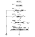
- the full charge capacity correction mode shifts as follows based on the flowchart of FIG. That is, when it is detected that the power storage device 8 is operating in the normal operation mode and the secondary battery unit 10 is fully charged by charging (STEP1, full charge detection process), the first full charge or the previous full charge is performed. It is determined whether a predetermined period T1 has elapsed since the capacity correction mode was performed (STEP 2).
- the first one detects the fully charged state when the maximum voltage Vmax in the secondary battery groups 20a to 20e constituting the secondary battery unit 10 reaches a predetermined voltage.
- the fully charged state is detected when the total voltage of the secondary battery groups 20a to 20e reaches a predetermined voltage.
- predetermined voltages are voltages corresponding to a predetermined charging rate set in advance, and are voltages serving as charging thresholds. Naturally, each value is different between the former and the latter.
- the “predetermined period T1” is a period during which it is expected that some change has occurred in the full charge capacity of the secondary battery unit 10.
- the “predetermined period T1” is preferably set to 20 days or more from the viewpoint of implementation frequency, and is preferably set to 90 days or less from the viewpoint of preventing overvoltage due to a mismatch of full charge capacities. In the present embodiment, the “predetermined period T1” is set to 30 days.
- a predetermined time period T1 has passed since the first full charge capacity correction mode was performed at the first activation or the previous full charge capacity was set (Yes in STEP 2), and no charge current was detected.
- a predetermined battery capacity hereinafter also referred to as a set capacity
- a set capacity preset on the external load 100 side is reached based on a power request from the external load 100. Discharge.
- the voltage applied to the secondary battery unit 10 and the current passing through the secondary battery unit 10 are monitored by the voltage detection means 11a to 11e and the current detection means 12.
- the set capacity is preferably 10% or more and 50% or less of the full charge capacity set initially or the full charge capacity set in the previous full charge capacity correction mode, and is 20% or more and 40% or less. It is more preferable. That is, the charging rate (hereinafter also referred to as SOC), which is the ratio of the amount of electricity charged to the electric capacity at OCV, is preferably 10% or more and 50% or less, and 20% or more and 40% or less. It is more preferable. Within this range, the consumed capacity DCR can be calculated more accurately in the consumed capacity calculating operation described later. In the present embodiment, the charging rate corresponding to the OCV is set to be 30% of the fully charged state.
- the full charge capacity correction mode is set.
- the charging current and the discharging current are substantially limited to 0 A (STEP 5). That is, the current balance from the outside of the power storage device 8 is substantially 0 A, and a pseudo open circuit state is formed.
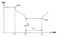
- a predetermined time T2 in a state where there is no request to cancel the full charge capacity correction mode. (STEP 7). That is, without performing the charging / discharging operation of the secondary battery unit 10, the apparatus waits until the predetermined time T ⁇ b> 2 elapses in a state where the current balance is substantially 0 A and the set capacity is maintained.
- the predetermined time T2 is a time until the OCV is sufficiently stabilized, and is preferably 100 minutes or more and 200 minutes or less, and more preferably 120 minutes or more and 180 minutes or less.
- the predetermined time T2 is 150 minutes.
- a time T3 during which the current and voltage states of the secondary battery unit 10 are not updated is provided on the display device after the battery capacity reaches the set capacity. That is, on the display device, the image, characters, etc. in the current current and voltage state are displayed for the time T3, and the images, characters, etc. in the actual current and voltage states are not displayed.
- the time T3 is preferably 10 seconds or longer and 20 seconds or shorter. In the present embodiment, the time T3 is 15 seconds.
- the OCV update operation will be described.
- calculation of the following formulas (1) and (2) is performed to calculate the charging rate SOC OCV and the remaining capacity RC, and the charging rate SOC OCV is reset.
- the open circuit voltage V OCV of the entire secondary battery unit 10 at time t3 shown in FIG. 6 is obtained by the voltage detection means 11a to 11e and / or the current detection means 12, and the open circuit voltage V calculating the average voltage V2 OCV of the open circuit voltage of each secondary cell group 20a ⁇ 20e from OCV.
- the correlation table see FIG.
- the charge rate SOC OCV in the open circuit state is calculated. That is, the charging is performed with respect to the average voltage V1 OCV of the secondary battery groups 20a to 20e corresponding to the time t3 shown in the previous FIG. 6 and the electric capacity at the OCV set in the previous full charge capacity correction mode.
- the charge rate SOC OCV in the actual open circuit state is calculated using the charge rate SOC V1 which is the ratio of the quantities.
- the formula (2) is used by using the full charge capacity FCC1 updated or reset in the initial setting or the previous full charge capacity correction mode. Accordingly, the remaining capacity RC is calculated (remaining capacity calculating operation). That is, the actual charge capacity in the open circuit state at the current time t3 is calculated according to the equation (2).
- the FCC update operation using the remaining capacity RC calculated by the OCV update operation and the consumed capacity DCR, which is an integrated value of the current amount from the start of discharging from the fully charged state to the set capacity, the following formula ( 3)
- the calculation of (4) is performed to calculate the full charge capacity FCC2, and this is updated or reset as FCC1 to be used thereafter.
- the amount of current from the time t1 when the discharge starts to the time t2 when the discharge starts to the time t2 when the set capacity is reached is integrated, and the remaining capacity after the discharge starts.
- the consumed capacity DCR consumed up to RC is calculated (consumption capacity calculating operation).
- the remaining capacity RC calculated by the remaining capacity calculating operation and the consumed capacity DCR calculated by the consumed capacity calculating operation are added by the following formula (4), and the actual full charge capacity FCC2 is updated as the full charge capacity or Reset it.
- the power generation device 2 is connected to the power storage device 8 via the power conversion device 7 as shown in FIG. Therefore, the power storage device 8 can directly charge DC power generated by the power generation device 2.
- the power generation device 2 is electrically connected to the external load 100 via the power conversion device 7 and the power supply control device 3. Therefore, the DC power generated by the power generator 2 can be converted to AC power by the power converter 7 and supplied to the external load 100.
- the power storage device 8 is electrically connected to the external load 100 via the power conversion device 7 and the power supply control device 3. Therefore, the DC power stored in the power storage device 8 can be converted into AC power by the power conversion device 7 and supplied to the external load 100.
- the power storage device 8 is electrically connected to the system power supply 101 via the power conversion device 7 and the power supply control device 3. Therefore, AC power supplied from the system power supply 101 can be converted into DC power by the power conversion device 7 and stored in the power storage device 8. In other words, the power storage device 8 can be charged with AC power supplied from the system power supply 101 as DC power.
- the full charge capacity correction mode is performed on the condition that only the discharge from the full charge capacity to the set capacity is performed, and the initial OCV or the previous OCV and the current OCV are obtained.
- the current remaining capacity RC is calculated by comparison, the consumed capacity DCR is calculated by integrating the amount of current from the fully charged state to the predetermined SOC state, and the sum of the remaining capacity RC and the consumed capacity DCR is calculated as the actual full capacity.
- Full charge capacity can be set. Further, since the control according to the full charge capacity set in practice can be performed, overvoltage and overcharge of each of the secondary battery groups 20a to 20e can be prevented. Therefore, the power storage device 8 can mount a large number of secondary batteries, and can incorporate a large-capacity secondary battery unit 10.
- the present invention is not limited to this.
- the full charge capacity correction mode when there is almost no change in the OCV compared to the past OCV, or when the OCV increases compared to the past OCV, the full charge capacity, OCV, SOC, etc. are updated. You don't have to.
- the deterioration state may be calculated based on the FCC calculated based on the full charge capacity correction mode.
- the SOH can be calculated by dividing the FCC by the design capacity (DC).
- the time T3 during which the current and voltage states of the secondary battery unit 10 are not updated is provided in the display device after the battery capacity reaches a predetermined battery capacity (SOC V2 ). Is not limited to this.
- the current state of the current and voltage of the secondary battery unit 10 may always be displayed on the display device, or may not be displayed. Further, a screen different from the current and voltage states may be displayed.
- the charging current and discharging current to the secondary battery unit 10 are substantially limited to 0 A by the program in the full charge capacity correction mode, but the present invention is not limited to this. Absent.
- the secondary battery unit 10 may be electrically disconnected from the power converter 7 by the switching unit 16 to form an open circuit, and the charging current and discharging current may be limited to 0A.
- voltage detection means 11a to 11e are provided corresponding to each of the secondary battery groups 20a to 20e, and the voltage detection means 11a to 11e only detect the voltage of each of the secondary battery groups 20a to 20e.
- the OCV update operation is performed by the charge / discharge control unit 15, the present invention is not limited to this.
- the voltage detection means 11a to 11e include a CPU (central processing unit) that performs various arithmetic processes, a ROM that is a main memory, a RAM that temporarily stores various data, a communication I / F, and an HDD.
- a storage device such as a (hard disk drive) may be provided, and the OCV update operation may be performed by each of the voltage detection units 11a to 11e.
- the voltages of the secondary battery groups 20a to 20e are directly detected by the voltage detectors 11a to 11e, but the present invention is not limited to this.
- Information regarding the voltage of the secondary battery groups 20a to 20e may be detected by the voltage detection means 11a to 11e, and the voltage may be indirectly detected.
- the “information about voltage” here is information corresponding to the voltage on a one-to-one basis.
- the secondary battery unit 10 includes the five secondary battery groups 20a to 20e, but the present invention is not limited to this.
- the number of secondary battery groups 20 in the secondary battery unit 10 is not particularly limited. That is, the number of secondary battery groups 20 in the secondary battery unit 10 may be one, or two or more.
- the secondary battery group 20 is composed of a plurality of secondary batteries, but the present invention is not limited to this.
- the secondary battery group 20 may be composed of a single secondary battery.
- discharge is performed based on the power demand from the external load 100 from the full charge capacity to the set capacity, and it is left to the progress of the discharge environment, but the present invention is limited to this. is not. For example, it may be forcibly discharged from the full charge capacity to the set capacity in accordance with the power supply to the power company or the like.
- the battery capacity is consumed by monotonous discharge from the full charge capacity to the set capacity, but the present invention is not limited to this. Charging may be performed between the fully charged capacity and the set capacity. In this case, in the consumed capacity calculation operation, the amount of current at the time of discharge is positive and the amount of current at the time of charge is negative. The amount of current is integrated.
- the voltage of the entire secondary battery unit 10 and the individual voltages of the secondary battery groups 20a to 20e are used to detect the fully charged state, but the present invention is not limited to this.
- the full charge state may be detected only by the voltage of the entire secondary battery unit 10, or the full charge state may be detected only by individual voltages of the secondary battery groups 20a to 20e.
- an actual secondary is obtained from a correlation table (correlation table shown in FIG. 5 as a graph) that represents the correlation between the open circuit voltage and the charging rate stored in advance in the storage device of the charge / discharge control unit 15.
- a correlation table correlation table shown in FIG. 5 as a graph
- the actual charge rate SOC V2 of the secondary battery unit 10 may be calculated from the correlation data representing the correlation between the open circuit voltage and the charge rate stored in advance in the storage device of the charge / discharge control unit 15.
- the remaining capacity RC is calculated by always integrating the amount of current detected by the current detection means 12 at the time of discharging, but the present invention is not limited to this. You may integrate what multiplied the elapsed time to the electric current amount detected with the electric current detection means 12 for every predetermined time.
- the full charge capacity correction mode when the full charge capacity correction mode is performed a plurality of times in the past, it is determined whether or not the predetermined period T1 has elapsed since the previous full charge capacity correction mode was performed.
- the reference date of the period T1 is not necessarily the previous full charge capacity correction mode, and may be based on the previous full charge capacity correction mode. That is, the full charge capacity correction mode may be performed when a predetermined period has elapsed from the previous full charge capacity setting than the previous time and only discharging is performed from the currently set full charge capacity to the set capacity. .
- each constituent member can be freely replaced or added between the embodiments as long as it is included in the technical scope of the present invention.
Landscapes
- Engineering & Computer Science (AREA)
- Chemical Kinetics & Catalysis (AREA)
- General Chemical & Material Sciences (AREA)
- Electrochemistry (AREA)
- Manufacturing & Machinery (AREA)
- Chemical & Material Sciences (AREA)
- Power Engineering (AREA)
- General Physics & Mathematics (AREA)
- Physics & Mathematics (AREA)
- Microelectronics & Electronic Packaging (AREA)
- Charge And Discharge Circuits For Batteries Or The Like (AREA)
- Tests Of Electric Status Of Batteries (AREA)
- Supply And Distribution Of Alternating Current (AREA)
- Secondary Cells (AREA)
Abstract
Description
ここでいう「満充電容量」とは、所定の基準により満充電状態とみなされた状態における充電容量である。
ここでいう「設定容量における第1電圧」とは、設定容量における電池部全体又は部分の電圧をいう。すなわち、「設定容量における第1電圧」は、電池部が単一の電池によって構成される場合には、電池部全体の電圧をいい、電池部が複数の電池によって構成されている場合には、電池部全体の電圧だけではなく、各電池の個々の電圧や一群の電圧も含む。
ここでいう「1C」とは、1時間の定電流放電によって放電終了となる電流値をいう。すなわち、「0.01C」とは、100時間の定電流放電によって放電終了となる電流値である。
ここで、理論上、電池部における電流収支を実質的に0にした状態で設定容量を維持した場合、電流収支がないので一定の電圧を示すはずである。
しかしながら、実際には設定容量まで放電のみを実施した直後は、電圧が乱れる傾向がある。そのため、電圧に連動する情報は、電圧の変動に伴って変化するので、使用者が電圧に連動する情報の表示を見たときに、故障等が生じたと感じる可能性がある。
そこで、本様相によれば、表示装置は、満充電容量補正モードにおいて、電池部が設定容量に至ってから所定の期間には、前記蓄電装置の電力に関する情報を更新しないので、使用者が表示装置に表示された情報を見たときに、故障等が生じたと感じることを防止できる。
電源システム1は、図1に示されるように、発電装置2と、電源制御装置3と、図示しない表示装置と、蓄電システム5を備えている。電源システム1は、電源制御装置3に外部負荷100と系統電源101が接続され、電力会社等から供給される商用電源たる系統電源101から供給された電力を外部負荷100に対して供給するものである。
電力変換装置7は、いわゆるパワーコンディショナーであり、交流電力を直流電力に変換することが可能となっている。すなわち、電力変換装置7は、発電装置2に電気的に接続することにより発電装置2で発電した直流電力を交流電力に変換して電源制御装置3に供給したり、系統電源101に電気的に接続することにより系統電源101から給電された交流電力を直流電力に変換して蓄電装置8に供給したりすることが可能となっている。
二次電池群20a~20eは、複数の二次電池が電気的に直列接続されたものである。
本実施形態の電流検知手段12は、放電電流を正とし、充電電流を負として検知している。すなわち、電流検知手段12は、1Aの放電電流が流れると「+1A」と検知し、1Aの充電電流が流れると「-1A」と検知する。
充放電制御部15は、各電圧検知手段11a~11e及び電流検知手段12と無線又は有線によって接続され、各電圧検知手段11a~11e及び電流検知手段12が検知した情報に基づいて、所定の演算処理を実行可能な演算装置でもある。さらに、充放電制御部15は、電流検知手段12で検知した電流量を積算する積算処理を実施可能な電流量積算部でもある。
具体的には、充放電制御部15は、各種演算処理を行うCPU(中央演算装置)、主メモリであるROM、各種データを一時記憶するためのRAM、通信I/F、HDD(ハードディスクドライブ)等の記憶装置を備えている。
この通常運転モードでは、放電動作においてあらかじめ設定された電池容量以下に電圧がならないように設定されており、充電動作においてあらかじめ設定された電圧以上にならないように設定されている。
また、蓄電装置8は、この通常運転モードに加えて、所定の条件を満たすことによって、経時変化等による二次電池群20a~20eの各二次電池の容量低下を踏まえて実際の満充電容量(以下、FCCともいう)を更新又は再設定する満充電容量補正モードを繰り返し実行することが可能となっている。
具体的には、満充電容量補正モードは、図3のフローチャートに基づいて下記のように移行する。
すなわち、蓄電装置8が通常運転モードで稼働しており、充電により二次電池ユニット10が満充電状態となったことを検知すると(STEP1,満充電検知工程)、初回起動時又は前回の満充電容量補正モードを行ってから、所定の期間T1を経過しているか判定する(STEP2)。
ここで、本実施形態の電源システム1では、満充電状態を検知する方法として下記の2つの基準のどちらか一方の基準を満たすことで検知している。
具体的には、1つ目は、二次電池ユニット10を構成する二次電池群20a~20eの中の最大電圧Vmaxが所定の電圧に達することで満充電状態を検知する。
2つ目は、二次電池群20a~20eの総電圧が所定の電圧に達することで満充電状態を検知する。
これらの「所定の電圧」は、あらかじめ設定された所定の充電率に対応する電圧であり、充電の閾値となる電圧である。当然、それぞれの値は前者と後者で異なる。
また、「所定の期間T1」は、二次電池ユニット10の満充電容量にある程度変化が起こったであろうと予想される期間である。「所定の期間T1」は、実施頻度の観点から20日以上で設定されていることが好ましく、満充電容量の不一致による過電圧等を防止する観点から90日以下で設定されていることが好ましい。
本実施形態では、「所定の期間T1」を30日と設定している。
この際に、電圧検知手段11a~11e及び電流検知手段12によって、二次電池ユニット10に印加される電圧及び二次電池ユニット10を通過する電流を監視する。
ここで、設定容量は、初期設定された満充電容量又は前回の満充電容量補正モードで設定された満充電容量の10%以上50%以下であることが好ましく、20%以上40%以下であることがより好ましい。すなわち、OCVでの電気容量に対して充電している電気量の比率である充電率(以下、SOCともいう)が10%以上50%以下であることが好ましく、20%以上40%以下であることがより好ましい。
この範囲であれば、後述する消費容量算出動作において、消費容量DCRをより正確に算出できる。
本実施形態では、OCVに対応する充電率が満充電状態の30%になるように設定している。
所定時間T2は、OCVが十分に安定するまでの時間であり、100分以上200分以下であることが好ましく、120分以上180分以下であることがより好ましい。本実施形態では、所定時間T2は、150分である。
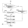
なお、本実施形態の蓄電装置8では、電池容量が設定容量に到達してから、表示装置に二次電池ユニット10の電流及び電圧の状態を更新しない時間T3を設けている。すなわち、表示装置では、時間T3の間、直前の電流及び電圧の状態の画像や文字等が表示されたままとなっており、実際の電流及び電圧の状態の画像や文字等は表示されない。
時間T3は、10秒以上20秒以下であることが好ましい。本実施形態では、時間T3は、15秒である。
OCVアップデート動作では、下記数式(1)~(2)の演算を行って充電率SOCOCV及び残容量RCを算出し、充電率SOCOCVを再設定する。
具体的には、まず、電圧検知手段11a~11e及び/又は電流検知手段12によって、図6に示される時刻t3における二次電池ユニット10全体の開回路電圧VOCVを取得し、開回路電圧VOCVから各二次電池群20a~20eの開回路電圧の平均電圧V2OCVを算出する。そして、あらかじめ充放電制御部15の記憶装置で記憶させた開回路電圧(OCV)と充電率(SOC)の相関関係を表す相関表(図5参照)から、実際の二次電池ユニット10の充電率SOCV2を算出する。
また、電圧検知手段11a~11eによって、図6に示される時刻t3における各二次電池群20a~20eの開回路電圧を計測し、二次電池ユニット10の中の二次電池群20a~20eの各開回路電圧の中での最小電圧Vminを取得する。
そして、あらかじめ設定された初期設定又は前回の満充電容量補正モードで再設定された二次電池群20a~20eの平均電圧V1OCV及び充電率SOCV1を用いて、下記の数式(1)に従って、開回路状態の充電率SOCOCVを算出する。すなわち、前回の図6に示される時刻t3に対応する二次電池群20a~20eの平均電圧V1OCV及び前回の満充電容量補正モードで設定したOCVでの電気容量に対して充電している電気量の比率たる充電率SOCV1を用いて、実際の開回路状態の充電率SOCOCVを算出する。


FCCアップデート動作では、上記したOCVアップデート動作によって算出した残容量RCと、満充電状態から放電を開始してから設定容量になるまでの電流量の積算値たる消費容量DCRを用いて、下記数式(3),(4)の演算を行って満充電容量FCC2を算出し、これを以後使用するFCC1として更新又は再設定する。
具体的には、下記の数式(3)によって、満充電状態となってから放電を開始する時刻t1から設定容量になった時刻t2までの電流量を積算し、放電を開始してから残容量RCになるまでに消費した消費容量DCRを算出する(消費容量算出動作)。
そして、下記の数式(4)によって、残容量算出動作によって算出した残容量RCと、消費容量算出動作によって算出した消費容量DCRを和算し、実際の満充電容量FCC2を満充電容量として更新又は再設定する。

発電装置2は、電力変換装置7及び電源制御装置3を経由して外部負荷100と電気的に接続されている。そのため、発電装置2で発電した直流電力を電力変換装置7で交流電力に変換して外部負荷100に給電できる。
蓄電装置8は、電力変換装置7及び電源制御装置3を経由して外部負荷100と電気的に接続されている。そのため、蓄電装置8で蓄電した直流電力を電力変換装置7で交流電力に変換して外部負荷100に給電できる。
蓄電装置8は、電力変換装置7及び電源制御装置3を経由して系統電源101と電気的に接続されている。そのため、系統電源101から供給される交流電力を電力変換装置7で直流電力に変換して蓄電装置8に蓄電できる。言い換えると、蓄電装置8は、系統電源101から供給される交流電力を直流電力として充電可能となっている。
すなわち、独立した異なる基準によって消費容量DCRと残容量RCをそれぞれ算出して実際の満充電容量を設定するため、二次電池ユニット10の劣化による二次電池ユニット10の容量低下に応じた実際の満充電容量を設定できる。また、実際に則して設定された満充電容量に伴った制御を行うことができるので、各二次電池群20a~20eの過電圧や過充電を防止できる。それ故に、蓄電装置8は、多数の二次電池を実装でき、大容量の二次電池ユニット10を内蔵できる。
ここでいう「電圧に関する情報」とは、電圧と1対1で対応する情報をいう。
2 発電装置
3 電源制御装置
5 蓄電システム
7 電力変換装置
8 蓄電装置
9 制御ユニット(制御部)
10 二次電津ユニット(電池部)
11a~11e 電圧検知手段(電圧情報検知手段)
12 電流検知手段
15 充放電制御部
16 切替部
20a~20e 二次電池群
Claims (9)
- 電池部と、前記電池部の充放電を制御する制御部を有し、
前記電池部は、満充電容量からあらかじめ設定された設定容量まで放電可能であり、
前記制御部は、満充電容量補正モードを実行可能であり、
前記満充電容量補正モードは、前記電池部が前記満充電容量から前記設定容量まで放電した場合に、あらかじめ設定された前記電池部の電圧と電池容量の相関関係に基づいて、前記設定容量まで放電した状態の第1電圧に対応する残容量を算出する残容量算出動作と、
前記満充電容量から前記設定容量までの間の前記電池部の電流量を演算して、前記満充電容量から前記設定容量までに消費した消費容量を算出する消費容量算出動作を実施し、
前記残容量と前記消費容量の和を満充電容量として設定することを特徴とする蓄電装置。 - 前記満充電容量補正モードは、前記電池部が前記満充電容量から前記設定容量まで放電のみを実施した場合に実施することを特徴とする請求項1に記載の蓄電装置。
- 前記制御部は、前記電池部の電圧を検知する電圧検知手段を有し、前記電池部における電流収支を実質的に0にして前記設定容量を維持した状態で、前記設定容量に至ってから所定時間を経過した後の前記電池部の電圧を前記第1電圧として取得することを特徴とする請求項1又は2に記載の蓄電装置。
- 前記電池部は、複数の二次電池群が直列接続されたものであり、
前記電圧検知手段は、各二次電池群の電圧を検知可能であり、
前記制御部は、前記電池部における電流収支を実質的に0にして前記設定容量の状態を維持した状態で、前記設定容量に至ってから所定時間を経過した後の各二次電池群の最小電圧を取得するものであり、
前記残容量算出動作は、前記第1電圧と前記最小電圧に基づいて前記残容量を算出することを特徴とする請求項3に記載の蓄電装置。 - 前記電池部は、複数の二次電池群が直列接続されたものであり、
前記制御部は、前記満充電容量補正モードを繰り返し実行するものであり、
前記満充電容量補正モードは、過去の満充電容量の設定から所定の期間が経過し、さらに前記満充電容量から前記設定容量まで放電のみを実施した場合に行うことを特徴とする請求項1から4のいずれか1項に記載の蓄電装置。 - 前記消費容量算出動作は、前記満充電容量から前記設定容量までの前記電池部の電流量を積算して前記消費容量を算出することを特徴とする請求項1から5のいずれか1項に記載の蓄電装置。
- 請求項1から6のいずれか1項に記載の蓄電装置と、交流電力と直流電力を変換する電力変換装置を有し、発電装置に対して電気的に接続可能な蓄電システムであって、
前記発電装置で発電した電力を蓄電装置に充電可能であることを特徴とする蓄電システム。 - 前記電力変換装置は、系統電源に対して電気的に接続可能であって、前記系統電源から供給される交流電力を直流電力に変換して前記蓄電装置に充電可能であることを特徴とする請求項7に記載の蓄電システム。
- 請求項1から6のいずれか1項に記載の蓄電装置と、前記蓄電装置の電力に関する情報を取得して表示可能な表示装置を有し、
前記制御部は、前記電池部における電流収支を実質的に0にして前記設定容量を維持した状態において、前記設定容量に至ってから所定時間を経過した後の前記電池部の電圧を前記第1電圧として取得するものであり、
前記表示装置は、前記満充電容量補正モードにおいて、前記電池部が前記設定容量に至ってから所定の期間の間、前記蓄電装置の電力に関する情報を更新しないことを特徴とする電源システム。
Priority Applications (4)
| Application Number | Priority Date | Filing Date | Title |
|---|---|---|---|
| CN201780042509.4A CN109477871B (zh) | 2016-07-08 | 2017-06-27 | 蓄电装置、蓄电系统以及电源系统 |
| US16/307,022 US20190219639A1 (en) | 2016-07-08 | 2017-06-27 | Electricity storage device, electricity storage system, and power supply system |
| JP2018526307A JP6932696B2 (ja) | 2016-07-08 | 2017-06-27 | 蓄電装置、蓄電システム、並びに、電源システム |
| EP17824075.0A EP3444625A4 (en) | 2016-07-08 | 2017-06-27 | POWER STORAGE DEVICE, POWER STORAGE SYSTEM AND POWER SUPPLY SYSTEM |
Applications Claiming Priority (2)
| Application Number | Priority Date | Filing Date | Title |
|---|---|---|---|
| JP2016136275 | 2016-07-08 | ||
| JP2016-136275 | 2016-07-08 |
Publications (1)
| Publication Number | Publication Date |
|---|---|
| WO2018008469A1 true WO2018008469A1 (ja) | 2018-01-11 |
Family
ID=60912649
Family Applications (1)
| Application Number | Title | Priority Date | Filing Date |
|---|---|---|---|
| PCT/JP2017/023552 WO2018008469A1 (ja) | 2016-07-08 | 2017-06-27 | 蓄電装置、蓄電システム、並びに、電源システム |
Country Status (5)
| Country | Link |
|---|---|
| US (1) | US20190219639A1 (ja) |
| EP (1) | EP3444625A4 (ja) |
| JP (1) | JP6932696B2 (ja) |
| CN (1) | CN109477871B (ja) |
| WO (1) | WO2018008469A1 (ja) |
Cited By (2)
| Publication number | Priority date | Publication date | Assignee | Title |
|---|---|---|---|---|
| WO2019135300A1 (ja) * | 2018-01-05 | 2019-07-11 | 株式会社カネカ | 蓄電装置、蓄電システム、電源システム、及び蓄電装置の制御方法 |
| WO2023053195A1 (ja) * | 2021-09-28 | 2023-04-06 | 武蔵精密工業株式会社 | 蓄電池管理装置および蓄電池の管理方法 |
Families Citing this family (7)
| Publication number | Priority date | Publication date | Assignee | Title |
|---|---|---|---|---|
| CN109463023B (zh) * | 2017-05-09 | 2022-07-08 | 合同会社崇朗环保系统 | 太阳能发电设备 |
| US10921381B2 (en) | 2017-07-28 | 2021-02-16 | Northstar Battery Company, Llc | Systems and methods for monitoring and presenting battery information |
| KR102458526B1 (ko) * | 2018-02-07 | 2022-10-25 | 주식회사 엘지에너지솔루션 | 배터리의 동작 상태에 따라 soc를 추정하는 장치 및 방법 |
| CN112540313B (zh) * | 2019-09-20 | 2022-05-13 | 比亚迪股份有限公司 | 修正电池可用容量的方法及车辆、介质 |
| CN112698225B (zh) * | 2019-10-22 | 2022-05-13 | 华为技术有限公司 | 一种电池容量跟踪方法、装置及电子设备 |
| CN113884884B (zh) * | 2021-10-21 | 2022-07-26 | 山东大学 | 一种基于相关性的动力电池组故障诊断方法及系统 |
| TWI788165B (zh) * | 2021-12-28 | 2022-12-21 | 台達電子工業股份有限公司 | 電源傳輸系統及方法 |
Citations (5)
| Publication number | Priority date | Publication date | Assignee | Title |
|---|---|---|---|---|
| JP2012145403A (ja) * | 2011-01-11 | 2012-08-02 | Denso Corp | リチウムイオン二次電池の電池容量検出装置 |
| JP2014102078A (ja) * | 2012-11-16 | 2014-06-05 | Toyota Motor Corp | 蓄電システムおよび満充電容量算出方法 |
| WO2014147899A1 (ja) * | 2013-03-18 | 2014-09-25 | 株式会社豊田自動織機 | 満充電容量推定方法及び装置 |
| JP2015118021A (ja) * | 2013-12-19 | 2015-06-25 | 日産自動車株式会社 | 劣化状態検出装置 |
| JP2015202010A (ja) * | 2014-04-10 | 2015-11-12 | 三菱電機株式会社 | 蓄電池の制御装置 |
Family Cites Families (7)
| Publication number | Priority date | Publication date | Assignee | Title |
|---|---|---|---|---|
| CN1182407C (zh) * | 2003-01-16 | 2004-12-29 | 华南理工大学 | 锂离子电池电量的测量方法及其装置 |
| KR100802912B1 (ko) * | 2005-12-08 | 2008-02-13 | 주식회사 엘지화학 | 배터리 충전용량 및 방전제한 전압 보정방법 및 장치 |
| JP4509040B2 (ja) * | 2006-02-08 | 2010-07-21 | 三洋電機株式会社 | パック電池の制御方法 |
| CN101282381A (zh) * | 2007-04-03 | 2008-10-08 | 乐金电子(中国)研究开发中心有限公司 | 显示电池剩余电量的装置与方法 |
| KR101288302B1 (ko) * | 2011-09-01 | 2013-07-19 | 삼성에스디아이 주식회사 | 배터리 팩, 및 이의 제어방법 |
| US9146280B2 (en) * | 2011-10-26 | 2015-09-29 | Industrial Technology Research Institute | Method and system for estimating a capacity of a battery |
| JP2013156202A (ja) * | 2012-01-31 | 2013-08-15 | Sanyo Electric Co Ltd | 二次電池の残容量算出方法及びパック電池 |
-
2017
- 2017-06-27 EP EP17824075.0A patent/EP3444625A4/en active Pending
- 2017-06-27 CN CN201780042509.4A patent/CN109477871B/zh active Active
- 2017-06-27 JP JP2018526307A patent/JP6932696B2/ja active Active
- 2017-06-27 WO PCT/JP2017/023552 patent/WO2018008469A1/ja active Application Filing
- 2017-06-27 US US16/307,022 patent/US20190219639A1/en not_active Abandoned
Patent Citations (5)
| Publication number | Priority date | Publication date | Assignee | Title |
|---|---|---|---|---|
| JP2012145403A (ja) * | 2011-01-11 | 2012-08-02 | Denso Corp | リチウムイオン二次電池の電池容量検出装置 |
| JP2014102078A (ja) * | 2012-11-16 | 2014-06-05 | Toyota Motor Corp | 蓄電システムおよび満充電容量算出方法 |
| WO2014147899A1 (ja) * | 2013-03-18 | 2014-09-25 | 株式会社豊田自動織機 | 満充電容量推定方法及び装置 |
| JP2015118021A (ja) * | 2013-12-19 | 2015-06-25 | 日産自動車株式会社 | 劣化状態検出装置 |
| JP2015202010A (ja) * | 2014-04-10 | 2015-11-12 | 三菱電機株式会社 | 蓄電池の制御装置 |
Non-Patent Citations (1)
| Title |
|---|
| See also references of EP3444625A4 * |
Cited By (2)
| Publication number | Priority date | Publication date | Assignee | Title |
|---|---|---|---|---|
| WO2019135300A1 (ja) * | 2018-01-05 | 2019-07-11 | 株式会社カネカ | 蓄電装置、蓄電システム、電源システム、及び蓄電装置の制御方法 |
| WO2023053195A1 (ja) * | 2021-09-28 | 2023-04-06 | 武蔵精密工業株式会社 | 蓄電池管理装置および蓄電池の管理方法 |
Also Published As
| Publication number | Publication date |
|---|---|
| CN109477871A (zh) | 2019-03-15 |
| JPWO2018008469A1 (ja) | 2019-04-25 |
| CN109477871B (zh) | 2021-12-17 |
| EP3444625A4 (en) | 2020-01-15 |
| JP6932696B2 (ja) | 2021-09-08 |
| US20190219639A1 (en) | 2019-07-18 |
| EP3444625A1 (en) | 2019-02-20 |
Similar Documents
| Publication | Publication Date | Title |
|---|---|---|
| WO2018008469A1 (ja) | 蓄電装置、蓄電システム、並びに、電源システム | |
| JP6991247B2 (ja) | 蓄電装置、蓄電システム、電源システム、及び蓄電装置の制御方法 | |
| JP5816906B2 (ja) | 蓄電池状態監視システム | |
| US7541775B2 (en) | Enhanced-accuracy battery capacity prediction using multiple discharge curves | |
| JP5815195B2 (ja) | 電池状態検知装置及びそれを内蔵する電池パック | |
| JP6225905B2 (ja) | 制御方法およびそれを利用した制御装置 | |
| US20150070024A1 (en) | Battery pack, apparatus including battery pack, and method of managing battery pack | |
| WO2012002429A1 (ja) | 充放電制御装置 | |
| WO2016051722A1 (ja) | 蓄電装置、制御装置、蓄電システム、蓄電装置の制御方法および制御プログラムを格納した非一時的なコンピュータ可読媒体 | |
| JP5919566B2 (ja) | 制御方法およびそれを利用した制御装置 | |
| JP2007178401A (ja) | 二次電池管理装置、二次電池管理方法及びプログラム | |
| JP6991591B2 (ja) | バッテリの充電状態の予測方法 | |
| WO2015056634A1 (ja) | 蓄電システム | |
| CN107076800A (zh) | 电池容量监测器 | |
| JP5314626B2 (ja) | 電源システム、放電制御方法および放電制御プログラム | |
| JP5620423B2 (ja) | 電子機器及び電子機器のバッテリ充電方法 | |
| WO2013002343A1 (ja) | 電池状態検出装置 | |
| JP2018045844A (ja) | 蓄電装置診断システムおよび蓄電装置診断方法 | |
| JP2018042320A (ja) | 蓄電システム | |
| JP2017010813A (ja) | 電力供給システム | |
| JP2021197769A (ja) | 亜鉛電池の劣化状態推定方法及び電源システム | |
| JP2007155434A (ja) | 二次電池の残存容量検出方法 | |
| JP2017067627A (ja) | 電池管理システム | |
| JP2004191151A (ja) | 二次電池の残存容量演算装置及びその残存容量演算方法 |
Legal Events
| Date | Code | Title | Description |
|---|---|---|---|
| WWE | Wipo information: entry into national phase |
Ref document number: 2018526307 Country of ref document: JP |
|
| WWE | Wipo information: entry into national phase |
Ref document number: 2017824075 Country of ref document: EP |
|
| ENP | Entry into the national phase |
Ref document number: 2017824075 Country of ref document: EP Effective date: 20181114 |
|
| 121 | Ep: the epo has been informed by wipo that ep was designated in this application |
Ref document number: 17824075 Country of ref document: EP Kind code of ref document: A1 |
|
| NENP | Non-entry into the national phase |
Ref country code: DE |