WO2018003056A1 - 物体追跡方法及び物体追跡装置 - Google Patents
物体追跡方法及び物体追跡装置 Download PDFInfo
- Publication number
- WO2018003056A1 WO2018003056A1 PCT/JP2016/069420 JP2016069420W WO2018003056A1 WO 2018003056 A1 WO2018003056 A1 WO 2018003056A1 JP 2016069420 W JP2016069420 W JP 2016069420W WO 2018003056 A1 WO2018003056 A1 WO 2018003056A1
- Authority
- WO
- WIPO (PCT)
- Prior art keywords
- object tracking
- objects
- concealment
- unit
- positional relationship
- Prior art date
Links
Images


Classifications
-
- G—PHYSICS
- G06—COMPUTING; CALCULATING OR COUNTING
- G06T—IMAGE DATA PROCESSING OR GENERATION, IN GENERAL
- G06T7/00—Image analysis
- G06T7/20—Analysis of motion
- G06T7/246—Analysis of motion using feature-based methods, e.g. the tracking of corners or segments
-
- G—PHYSICS
- G06—COMPUTING; CALCULATING OR COUNTING
- G06T—IMAGE DATA PROCESSING OR GENERATION, IN GENERAL
- G06T7/00—Image analysis
- G06T7/20—Analysis of motion
-
- G—PHYSICS
- G08—SIGNALLING
- G08G—TRAFFIC CONTROL SYSTEMS
- G08G1/00—Traffic control systems for road vehicles
- G08G1/16—Anti-collision systems
Definitions
- the present invention relates to an object tracking method and an object tracking apparatus.
- Patent Document 1 determines whether or not an object has reappeared based on prediction information of a concealed object, and assigns the same identification number to the reappearing object.
- Patent Document 1 causes a shift in the prediction information, and the object that reappears is erroneous. There is a risk of assigning an identification number.
- the present invention has been made in view of the above problems, and its purpose is to give erroneous identification information before and after being concealed even when a plurality of objects enter the concealment area and disappear temporarily. It is an object of the present invention to provide an object tracking method and an object tracking apparatus that can prevent the above.
- the positional relationship of the plurality of objects in the concealment region is estimated, and when the object comes out of the concealment region, the estimated position Based on the relationship, object identification information is determined.
- the present invention even when a plurality of objects enter the concealment area and disappear temporarily, it is possible to prevent erroneous identification information from being added before and after the concealment.
- FIG. 1 is a configuration diagram of an object tracking apparatus according to the first embodiment of the present invention.
- FIG. 2A is a diagram for explaining an object tracking method according to the first embodiment of the present invention.
- FIG. 2B is a diagram for explaining an object tracking method according to the first embodiment of the present invention.
- FIG. 2C is a diagram for explaining an object tracking method according to the first embodiment of the present invention.
- FIG. 3 is a diagram for explaining a concealment area according to the first embodiment of the present invention.
- FIG. 4A is a diagram illustrating a method for determining object identification information according to the first embodiment of the present invention.
- FIG. 4B is a diagram illustrating a method for determining object identification information according to the first embodiment of the present invention.
- FIG. 4C is a diagram illustrating a method for determining object identification information according to the first embodiment of the present invention.
- FIG. 4D is a diagram illustrating a method for determining object identification information according to the first embodiment of the present invention.
- FIG. 5 is a diagram for explaining the tracker of the object that has come out of the concealment area according to the first embodiment of the present invention.
- FIG. 6 is a flowchart for explaining an operation example of the object tracking apparatus according to the first embodiment of the present invention.
- FIG. 7A is a diagram illustrating a method for determining object identification information according to the second embodiment of the present invention.
- FIG. 7B is a diagram illustrating a method for determining object identification information according to the second embodiment of the present invention.
- FIG. 7C is a diagram illustrating a method for determining object identification information according to the second embodiment of the present invention.
- FIG. 7D is a diagram illustrating a method for determining object identification information according to the second embodiment of the present invention.
- FIG. 8A is a diagram for explaining an object identification information determination method according to the second embodiment of the present invention.
- FIG. 8B is a diagram illustrating a method for determining object identification information according to the second embodiment of the present invention.
- FIG. 8C is a diagram illustrating a method for determining object identification information according to the second embodiment of the present invention.
- FIG. 9 is a diagram for explaining a tracker of an object that has come out of the concealment area according to the second embodiment of the present invention.
- FIG. 9 is a diagram for explaining a tracker of an object that has come out of the concealment area according to the second embodiment of the present invention.
- FIG. 10 is a flowchart for explaining an operation example of the object tracking apparatus according to the second embodiment of the present invention.
- FIG. 11A is a diagram illustrating a method for determining object identification information according to the third embodiment of the present invention.
- FIG. 11B is a diagram for explaining an object identification information determination method according to the third embodiment of the present invention.
- FIG. 11C is a diagram illustrating a method for determining object identification information according to the third embodiment of the present invention.
- FIG. 12A is a diagram for explaining an object identification information determination method according to the third embodiment of the present invention.
- FIG. 12B is a diagram illustrating a method for determining object identification information according to the third embodiment of the present invention.
- FIG. 13 is a flowchart for explaining an operation example of the object tracking apparatus according to the third embodiment of the present invention.
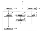
- the object tracking device 100 includes an object detection unit 10, a map information acquisition unit 20, and a controller 30.
- the object detection unit 10 is a sensor that periodically detects an object around a moving body (vehicle), and is, for example, a laser range finder.
- the laser range finder detects objects (pedestrians, bicycles, two-wheeled vehicles, other vehicles, etc.) existing around the host vehicle (for example, within 30 m) that is a moving body. More specifically, the laser range finder scans the laser light within a certain angle range, receives the reflected light at that time, and detects the time difference between the time of laser emission and the time of receiving the reflected light. Thereby, the laser range finder detects the relative distance and relative speed of the object with respect to the host vehicle, the moving direction of the object, and the like.
- the object detection unit 10 outputs information on the detected object to the controller 30. Note that an infrared sensor, an ultrasonic sensor, a camera, or the like may be used as the object detection unit 10.
- the object detection unit 10 outputs the detection result to the controller 30.
- the map information acquisition unit 20 is a device that acquires map information, for example, a navigation device.
- the map information is, for example, the number of road lanes, junction points, traffic rules, and the like.
- the map information acquisition unit 20 outputs the acquired map information to the controller 30.
- the map information acquisition part 20 may acquire map information from a storage medium, and may acquire map information from a server.
- the controller 30 is a circuit that processes data acquired from the object detection unit 10 and the map information acquisition unit 20, and is configured by an IC, an LSI, or the like, for example. When the controller 30 grasps this functionally, the controller 30 can classify the object tracking unit 31, a concealment region calculation unit 32, a positional relationship estimation unit 33, a route calculation unit 34, and an identification number assigning unit 35. it can.
- the object tracking unit 31 tracks the object by associating the parameter of the currently detected object with the parameter of the object detected in the past.
- the parameters of the object are the position of the object, the speed of the object, the size of the object, the moving direction of the object, the color of the object, and the like. If the object tracking unit 31 cannot associate the parameters of the object, the object tracking unit 31 determines that the object has disappeared. Further, when the object disappears within the detection range of the sensor, the object tracking unit 31 determines that the object has entered the hidden area.
- the hidden area calculation unit 32 calculates a hidden area.
- the hidden area is an area where the object is hidden by an obstacle and the object detection unit 10 cannot detect the object. Details of the hidden area will be described later.
- the positional relationship estimation unit 33 estimates the positional relationship of the plurality of concealed objects using the parameters of the plurality of objects before the disappearance. .
- the route calculation unit 34 calculates lanes and routes that can change the course of the concealed object based on the map information acquired from the map information acquisition unit 20.
- the identification number assigning unit 35 assigns an identification number to the object detected by the object detecting unit 10. Further, the identification number assigning unit 35 continuously assigns the same identification number to the object associated by the object tracking unit 31, and assigns a new identification number to the newly detected object. Further, the identification number assigning unit 35 assigns an identification number to the object that has come out of the concealment region based on the positional relationship of the plurality of objects acquired from the positional relationship estimation unit 33 and the route calculation unit 34, a route that can be changed, and the like. Give.
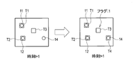
- the object tracking unit 31 sets trackers T1 to T3 for the objects 11 to 13.
- a tracker is information indicating the position and speed of an object.
- the identification number assigning unit 35 assigns identification numbers ID1 to ID3 to the objects 11 to 13.
- the tracker and the identification number are identification information for tracking an object.
- the object tracking unit 31 predicts the positions of the objects 11 to 13 at the time t + 1 based on the position information and speed information of the objects 11 to 13.
- the object tracking unit 31 changes the trackers T1 to T3 based on the predicted position.
- the object tracking unit 31 matches the information of the objects 11 to 12 and 14 detected at the time t + 1 with the trackers T1 to T3 which are changed at the time t.
- the object tracking unit 31 sets a new tracker T4 for the object 14 for which no corresponding tracker is found within a certain distance (for example, 6 m).
- the object tracking unit 31 sets a flag from 0 to 1 for a tracker T3 in which a corresponding object does not exist within a certain distance and exists more than a certain number of times. And the object tracking part 31 continues prediction using the positional information and speed information which tracker T3 has.
- a flag of 1 means a state in which no object exists within a certain distance of the tracker.
- a flag of 0 means a state in which an object exists within a certain distance of the tracker.
- the flags of the trackers T1 and T2 are 0.
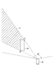
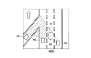
- the detection range of the object detection unit 10 is 160 ° in front of the host vehicle. This detection range is an example, and the detection range is widened by attaching the sensor to the side or rear of the vehicle.
- the hidden area calculation unit 32 calculates the hidden area R. Specifically, when the object detection unit 10 detects the other vehicle M1 on the left front side of the own vehicle, the concealment area calculation unit 32 is a straight line extending from the own vehicle M0 toward the corners P1 and P2 of the other vehicle M1. Of the regions formed by the above, the region concealed by the other vehicle M1 is calculated as the concealment region R.
- the corners P1, P2 of the other vehicle M1 are two points that are farthest from the host vehicle M0.
- FIGS. 4A to 4D a method for determining identification information when a plurality of objects enter the concealment region R will be described with reference to FIGS. 4A to 4D and FIG.
- the arrows in FIGS. 4A to 4D indicate the traveling direction of each vehicle.
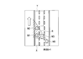
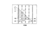
- the object tracking unit 31 sets trackers T1 to T3 for other vehicles M1 to M3 existing around the host vehicle M0.
- the identification number assigning unit 35 assigns identification numbers ID1 to ID3 to the other vehicles M1 to M3.
- the concealment area calculation unit 32 calculates the concealment area R concealed by the other vehicle M3.
- illustration of the trackers T1 to T3 is omitted. Also, the illustration of the tracker is omitted in the subsequent drawings.
- the route calculation unit 34 calculates a zone where the other vehicles M1 and M2 may come out of the concealment region R based on the map information.
- zones where the other vehicles M1 and M2 may come out of the concealment region R are zones X and Y.
- the positional relationship estimation unit 33 estimates the positional relationship between the other vehicles M1 and M2 in the concealment region R.
- the positional relationship of the plurality of objects in the concealment region R includes not only the positional relationship in the concealment region R but also the order of coming out from the zone.
- the positional relationship between the other vehicles M1 and M2 is that the other vehicle M2 exists in front of the other vehicle M1.
- the positional relationship estimation unit 33 can estimate the positional relationship shown in FIG. 4B from the positional information of the other vehicles M1 and M2 at time t.
- the positional relationship estimation unit 33 estimates the order in which the other vehicles M1 and M2 come out of the concealed region R into the zones X and Y.
- the order of coming out from the concealment area R to the zone X is the order of the other vehicles M1 and M2. Further, the order of coming out from the concealment region R to the zone Y is the order of the other vehicles M2 and M1.
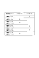
- the positional relationship estimation part 33 produces the table shown in FIG. 5 using the estimated order.
- the first zone Y indicates that the tracker T2 comes out first from the zone Y.
- the second zone Y indicates that the tracker T1 comes out of the zone Y second after the first object coming out of the zone Y is detected.
- the object detection unit 10 detects an object coming out of the concealment region R.
- the object tracking unit 31 collates the table shown in FIG. The information of the tracker T2 is continued. Then, the object tracking unit 31 sets the flag of the tracker T2 to 0. Moreover, the identification number provision part 35 continues identification number ID2 with respect to the other vehicle M2.
- the object tracking unit 31 collates the table shown in FIG.
- the information of the tracker T1 is continued for M1, and the flag of the tracker T1 is set to 0.
- the identification number provision part 35 continues identification number ID1 with respect to the other vehicle M1.
- step S101 the object detection unit 10 detects objects around the host vehicle.
- step S103 the object tracking unit 31 sets a tracker on the object and tracks the object.
- the identification number assigning unit 35 assigns an identification number to the object.
- step S105 the object tracking unit 31 determines whether or not a plurality of objects have disappeared. If a plurality of objects have disappeared (Yes in step S105), the process proceeds to step S107. On the other hand, when the plurality of objects have not disappeared (No in step S105), the process returns to step S103. Further, when the object tracking unit 31 determines that the plurality of objects have disappeared, the object tracking unit 31 sets the tracker flags of the plurality of objects to 1.
- step S107 the hidden area calculation unit 32 calculates a hidden area.
- step S109 the map information acquisition unit 20 acquires map information.
- step S111 the route calculation unit 34 calculates a zone where an object may come out of the concealment area based on the map information.
- step S113 the positional relationship estimation unit 33 estimates the positional relationship of a plurality of objects in the hidden area. In addition, the positional relationship estimation unit 33 estimates the order in which a plurality of objects come out of the concealment area into the zone based on the estimated positional relationship.
- step S115 if the object detection unit 10 detects an object that has come out of the concealment area (Yes in step S115), the process proceeds to step S117. On the other hand, if no object is detected (No in step S115), the process waits.
- step S117 the object tracking unit 31 collates the table generated by the positional relationship estimation unit 33.
- step S119 the object tracking unit 31 continues the tracker information based on the collation result of the table.
- step S121 the object tracking unit 31 sets the flag of the continued tracker to 0.
- step S123 the identification number assigning unit 35 determines the identification number of the object.
- step S125 the object tracking device 100 determines whether or not the ignition switch is off. If the ignition switch is on (No in step S125), the process returns to step S101. If the ignition switch is off (Yes in step S125), the object tracking device 100 ends a series of processes.
- the object tracking device 100 estimates the positional relationship of the plurality of objects in the concealment area when a plurality of objects enter the concealment area, and based on the estimated positional relation when the object comes out of the concealment area, Determine the identification information. As a result, even when a plurality of objects enter the concealment region and disappear temporarily, the object tracking device 100 can prevent erroneous identification information from being added before and after being concealed, and improve the object tracking performance. Can do.
- the object tracking device 100 can estimate the positional relationship of a plurality of objects in the concealment area, the object tracking device 100 continues the identification information before entering the concealment area when the object leaves the concealment area. As a result, even when a plurality of objects enter the concealment region and disappear temporarily, the object tracking device 100 can prevent erroneous identification information from being added before and after being concealed, and improve the object tracking performance. Can do.
- the object tracking device 100 has the same configuration as that of the first embodiment.
- the positional relationship between a plurality of objects is different.
- the positional relationship estimation unit 33 can estimate the positional relationship of a plurality of objects in the concealment region has been described.
- the positional relationship estimation part 33 demonstrates the case where the positional relationship of the several object in a concealment area cannot be estimated.
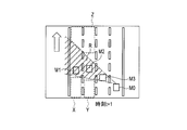
- the object tracking unit 31 sets trackers T1 to T3 for other vehicles M1 to M3 existing around the host vehicle M0.
- the identification number assigning unit 35 assigns identification numbers ID1 to ID3 to the other vehicles M1 to M3.
- the route calculation unit 34 calculates zones X, Y, and Z as zones where the other vehicles M1 and M2 may come out of the concealment region R based on the map information.
- the positional relationship estimation unit 33 estimates the positional relationship between the other vehicles M1 and M2 in the concealment region R.
- the positional relationship estimation unit 33 estimates the order in which the other vehicles appearing in the zones X, Y, and Z from the concealment region R and the other vehicles M1 and M2 appear in the zone Z from the concealment region R. It is the other vehicle M1 that comes out from the concealment region R to the zone X. In addition, the other vehicle M2 comes out from the concealment region R to the zone Y.
- the positional relationship estimation unit 33 cannot estimate the order of coming out of the concealment region R into the zone Z. The reason is that the other vehicle M1 or M2 may change the lane and come out from the concealment region R.
- the positional relationship estimation unit 33 creates the table shown in FIG. 9 using the estimated positional relationship.
- the object detection unit 10 detects an object coming out of the concealment region R.
- the object tracking unit 31 collates the table shown in FIG.
- the information on the tracker T1 is continued, and the flag of the tracker T1 is set to 0.
- the identification number provision part 35 continues identification number ID1 with respect to the other vehicle M1.
- the object tracking unit 31 checks the table shown in FIG. The information of the tracker T2 is continued for M2, and the flag of the tracker T2 is set to 0. Moreover, the identification number provision part 35 continues identification number ID2 with respect to the other vehicle M2.
- the object tracking unit 31 determines that the object 11 It cannot be determined whether the vehicle is M1 or another vehicle M2. Therefore, the object tracking unit 31 collates the table shown in FIG. 9 and sets a new tracker T4 for the object 11. Further, the identification number giving unit 35 gives a new identification number ID4 to the object 11. At this time, the object tracking unit 31 holds the information on the trackers T1 and T2 without deleting them.
- the object tracking unit 31 collates the table shown in FIG. 9 and sets a new tracker T5 for the object 12. Further, the identification number giving unit 35 gives a new identification number ID5 to the object 12. At this time, since the new identification number is assigned by the number of objects (two) that were in the concealment region R, the object tracking unit 31 determines that there is no object in the concealment region R and has retained the tracker. The information of T1 and T2 is deleted. That is, the object tracking unit 31 deletes the retained information when new identification numbers are assigned as many as the number of objects that have entered the concealment region R.
- the object tracking unit 31 uses the table shown in FIG. By collating, it can be determined that the object 12 is the other vehicle M2. Thereby, the object tracking part 31 can judge that the object 11 is the other vehicle M1. Therefore, the object tracking unit 31 continues the information on the trackers T1 and T2 with respect to the other vehicles M1 and M2, and sets the flags of the trackers T1 and T2 to 0. Moreover, the identification number provision part 35 deletes identification number ID4 newly provided to the other vehicle M1 at the time t + 2, and gives identification number ID1 continuously. Moreover, the identification number provision part 35 continues identification number ID2 with respect to the other vehicle M2.
- Step S201 to Step S217, Step S221 to Step S223, and Step S233 are the same as the operations of Step S101 to 117, Step S121 to Step S123, and Step S125 of FIG. Only the differences will be described.
- step S219 the object tracking unit 31 determines whether or not to continue tracker information.
- the process proceeds to step S221.
- the process proceeds to step S225.
- step S225 the identification number assigning unit 35 assigns a new identification number to the object that has come out of the concealment area.
- step S227 when all the objects that have entered the concealment area R are detected (Yes in step S227), the process proceeds to step S229. On the other hand, when there is an object that is not detected among the objects that have entered the concealment region R (No in step S227), the process returns to step S225.
- step S229 the object tracking unit 31 determines whether or not to continue tracker information again. Depending on the order of coming out of the hidden area, the object tracking unit 31 can continue the tracker information. If the object tracking unit 31 can continue the tracker information (Yes in step S229), the process proceeds to step S221. On the other hand, when the object tracking unit 31 cannot continue the tracker information (No in step S229), the process proceeds to step S231.
- step S231 the object tracking unit 31 deletes the tracker information held.
- the object tracking apparatus 100 When the object tracking apparatus 100 cannot estimate the positional relationship of a plurality of objects in the concealment area, the object tracking apparatus 100 gives new identification information to the object when the object exits the concealment area. Thereby, the object tracking device 100 can prevent erroneous identification information from being added before and after being concealed even when a plurality of objects enter the concealment area and disappear temporarily.
- Patent Document 1 there is a possibility that it may be determined that the other vehicle M2 has come out from the concealed region R first, despite the other vehicle M1. In this case, it is determined that the host vehicle M0 can pass the other vehicle M3 and change the lane to the left lane. This is because it is determined that the other vehicle M2 has come out of the concealment region R.
- the object tracking device 100 gives new identification information to the object 11 that comes out, and does not delete the information of the other vehicles M1 and M2. Thereby, the object tracking device 100 can take a reliable driving action.
- the object tracking device 100 determines that an object exists in the concealment area until new identification information is given as many as the number of objects in the concealment area. Then, the object tracking device 100 deletes the old identification information when new identification information is given by the number of objects in the hidden area. As a result, even when a plurality of objects enter the concealment region and disappear temporarily, the object tracking device 100 can prevent erroneous identification information from being added before and after being concealed, and improve the object tracking performance. Can do.
- the object tracking device 100 according to the third embodiment has the same configuration as that of the first embodiment.
- the traveling scene is different.
- a straight road without a branch has been described as a travel scene.
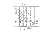
- a road where a collision point exists will be described.
- the collision point is a collision position on the locus of the other vehicles M1 and M2.
- the object tracking unit 31 sets trackers T1 to T3 for other vehicles M1 to M3 existing around the host vehicle M0.
- the identification number assigning unit 35 assigns identification numbers ID1 to ID3 to the other vehicles M1 to M3.
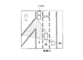
- the route calculation unit 34 calculates a collision point P where the other vehicle M1 and the other vehicle M2 may collide based on the map information.
- the positional relationship estimation unit 33 estimates the time T until the other vehicles M1 and M2 reach the collision point P. This time T is expressed by equation (1).
- the positional relationship between the plurality of objects includes not only the positional relationship within the concealment region R but also the time until the plurality of objects reach the collision point.
- the object tracking unit 31 uses the time T to determine whether or not to continue the tracker. Assuming that the time until the other vehicle M1 reaches the collision point P is time TM1, and the time until the other vehicle M2 reaches the collision point P is time TM2, the time difference until the other vehicle M2 reaches the collision point P is time TM2. -Time TM1. The object tracking unit 31 determines whether this time difference is equal to or longer than a predetermined time (for example, 2 seconds). When the time difference is equal to or longer than the predetermined time, the object tracking unit 31 determines that the other vehicle M2 in the priority lane reaches the collision point P first. That is, as illustrated in FIG.
- the object tracking unit 31 determines that the object that has come out of the concealment region R is the other vehicle M2.
- the object tracking unit 31 continues the tracker T2 information for the other vehicle M2, and sets the tracker T2 flag to 0.
- the identification number provision part 35 continues identification number ID2 with respect to the other vehicle M2.
- the object tracking unit 31 determines whether the object 11 is the other vehicle M1. It cannot be determined whether the vehicle M2. The reason is that the object tracking unit 31 cannot determine which vehicle has given way. Therefore, the object tracking unit 31 sets a new tracker T4 for the object 11. Further, the identification number giving unit 35 gives a new identification number ID4 to the object 11. At this time, the object tracking unit 31 holds the information on the trackers T1 and T2 without deleting them.
- the object tracking unit 31 determines that the object 12 is the other vehicle M1. Or other vehicle M2. Therefore, the object tracking unit 31 sets a new tracker T5 for the object 12. Further, the identification number giving unit 35 gives a new identification number ID5 to the object 12. At this time, since the new identification number is assigned by the number of objects (two) that were in the concealment region R, the object tracking unit 31 determines that there is no object in the concealment region R and has retained the tracker. The information of T1 and T2 is deleted.
- step S311 the positional relationship estimation unit 33 estimates the time until a plurality of objects reach the collision point.
- step S313 the object tracking unit 31 determines whether a time difference until a plurality of objects reach the collision point is equal to or longer than a predetermined time. If the time difference is equal to or greater than the predetermined time (Yes in step S313), the process proceeds to step S321. On the other hand, when the time difference is less than the predetermined time (No in step S313), the process proceeds to step S315.
- step S315 the identification number assigning unit 35 assigns a new identification number to the object that has come out of the concealment area.
- step S317 when all the objects that have entered the concealment region R are detected (Yes in step S317), the process proceeds to step S319. On the other hand, when there is an object that is not detected among the objects entering the concealment region R (No in step S317), the process returns to step S315.
- step S319 the object tracking unit 31 deletes the tracker information held.
- the object tracking device 100 estimates the time difference to the collision point, and when the time difference is smaller than the predetermined time, the object tracking device 100 gives new identification information to the object when the object leaves the concealment region. Thereby, the object tracking device 100 can prevent erroneous identification information from being added before and after being concealed even when a plurality of objects enter the concealment area and disappear temporarily. Further, in the example shown in FIG. 12A, in Patent Document 1, there is a possibility that it may be determined that the other vehicle M2 has come out despite the other vehicle M1 coming out of the concealment region R first. In this case, it is determined that the host vehicle M0 can pass the other vehicle M3 and change the lane to the left lane.
- the object tracking device 100 gives new identification information to the object 11 that comes out, and does not delete the information of the other vehicles M1 and M2. Thereby, the object tracking device 100 can take a reliable driving action.
- the processing circuit includes a programmed processing device such as a processing device including an electrical circuit.
- the processing circuitry also includes devices such as application specific integrated circuits (ASICs) and conventional circuit components arranged to perform the functions described in the embodiments.
- ASICs application specific integrated circuits
- the present invention can be applied to an automatically driven vehicle that automatically travels along a travel route.
Landscapes
- Engineering & Computer Science (AREA)
- Physics & Mathematics (AREA)
- General Physics & Mathematics (AREA)
- Multimedia (AREA)
- Computer Vision & Pattern Recognition (AREA)
- Theoretical Computer Science (AREA)
- Traffic Control Systems (AREA)
- Image Analysis (AREA)
- Radar Systems Or Details Thereof (AREA)
Abstract
Description
図1を参照して、第1実施形態に係る物体追跡装置100について説明する。図1に示すように、物体追跡装置100は、物体検出部10と、地図情報取得部20と、コントローラ30とを備える。
次に、本発明の第2実施形態について説明する。第2実施形態に係る物体追跡装置100は、第1実施形態と構成は同一である。第2実施形態では、複数の物体の位置関係が相違する。第1実施形態では、位置関係推定部33が隠蔽領域内の複数の物体の位置関係を推定できる場合を説明した。一方、第2実施形態では、位置関係推定部33が隠蔽領域内の複数の物体の位置関係を推定できない場合を説明する。
次に、本発明の第3実施形態について説明する。第3実施形態に係る物体追跡装置100は、第1実施形態と構成は同一である。第3実施形態では、走行シーンが相違する。第1実施形態では走行シーンとして分岐がない直線道路を説明したが、第3実施形態では衝突ポイントが存在する道路について説明する。
ここで、Lは衝突ポイントPまでの距離であり、Vは隠蔽領域Rに入る前の物体の速度である。なお、第3実施形態において複数の物体の位置関係は、隠蔽領域R内の位置の関係だけでなく、複数の物体が衝突ポイントに到達するまでの時間も含む。
10 物体検出部
20 地図情報取得部
30 コントローラ
31 物体追跡部
32 隠蔽領域算出部
33 位置関係推定部
34 ルート算出部
35 識別番号付与部
Claims (6)
- 移動体の周囲の物体を検出するセンサと、前記物体の検出結果に基づいて前記物体を追跡するコントローラと、を備えた物体追跡装置の物体追跡方法であって、
前記センサの検出範囲で、複数の物体が隠蔽領域に入った場合、前記隠蔽領域内での前記複数の物体の位置関係を推定し、前記隠蔽領域から前記物体が出たとき、推定した前記位置関係に基づいて、前記物体の識別情報を決定することを特徴とする物体追跡方法。 - 前記隠蔽領域内での前記複数の物体の位置関係を推定できる場合、前記物体が前記隠蔽領域に入る前の識別情報を前記物体が前記隠蔽領域から出たときに継続することを特徴とする請求項1に記載の物体追跡方法。
- 前記隠蔽領域内での前記複数の物体の位置関係を推定できない場合、前記物体が前記隠蔽領域を出たときに新しい識別情報を前記物体に付与することを特徴とする請求項1または2に記載の物体追跡方法。
- 前記複数の物体の軌跡の衝突位置までに到達する時間差が所定時間より小さい場合、前記物体が前記隠蔽領域を出てきたときに新しい識別情報を前記物体に付与することを特徴とする請求項3に記載の物体追跡方法。
- 前記新しい識別情報が前記隠蔽領域内にいた物体の数だけ付与されるまで前記隠蔽領域内に物体が存在すると判定することを特徴とする請求項3または4に記載の物体追跡方法。
- 移動体の周囲の物体を検出するセンサと、
前記センサによって検出された結果に基づいて前記物体を追跡するコントローラと、を備え、
前記コントローラは、前記センサの検出範囲で、複数の物体が隠蔽領域に入った場合、前記隠蔽領域内での前記複数の物体の位置関係を推定し、前記隠蔽領域から前記物体が出たとき、推定した前記位置関係に基づいて、前記物体の識別情報を決定することを特徴とする物体追跡装置。
Priority Applications (10)
| Application Number | Priority Date | Filing Date | Title |
|---|---|---|---|
| BR112018077393-0A BR112018077393A2 (pt) | 2016-06-30 | 2016-06-30 | método de rastreio de objeto e aparelho de rastreio de objeto |
| KR1020197002533A KR102091363B1 (ko) | 2016-06-30 | 2016-06-30 | 물체 추적 방법 및 물체 추적 장치 |
| CN201680087002.6A CN109313804B (zh) | 2016-06-30 | 2016-06-30 | 物体追踪方法及物体追踪装置 |
| US16/311,608 US10482612B2 (en) | 2016-06-30 | 2016-06-30 | Object tracking method and object tracking apparatus |
| RU2019102418A RU2699583C1 (ru) | 2016-06-30 | 2016-06-30 | Способ отслеживания объектов и устройство отслеживания объектов |
| MX2018015701A MX2018015701A (es) | 2016-06-30 | 2016-06-30 | Metodo de rastreo de objetos y aparato de rastreo de objetos. |
| PCT/JP2016/069420 WO2018003056A1 (ja) | 2016-06-30 | 2016-06-30 | 物体追跡方法及び物体追跡装置 |
| EP16907289.9A EP3480788A4 (en) | 2016-06-30 | 2016-06-30 | METHOD AND DEVICE FOR TRACKING OBJECTS |
| CA3029395A CA3029395A1 (en) | 2016-06-30 | 2016-06-30 | Object tracking method and object tracking apparatus |
| JP2018524655A JP6677297B2 (ja) | 2016-06-30 | 2016-06-30 | 物体追跡方法及び物体追跡装置 |
Applications Claiming Priority (1)
| Application Number | Priority Date | Filing Date | Title |
|---|---|---|---|
| PCT/JP2016/069420 WO2018003056A1 (ja) | 2016-06-30 | 2016-06-30 | 物体追跡方法及び物体追跡装置 |
Publications (1)
| Publication Number | Publication Date |
|---|---|
| WO2018003056A1 true WO2018003056A1 (ja) | 2018-01-04 |
Family
ID=60786130
Family Applications (1)
| Application Number | Title | Priority Date | Filing Date |
|---|---|---|---|
| PCT/JP2016/069420 WO2018003056A1 (ja) | 2016-06-30 | 2016-06-30 | 物体追跡方法及び物体追跡装置 |
Country Status (10)
| Country | Link |
|---|---|
| US (1) | US10482612B2 (ja) |
| EP (1) | EP3480788A4 (ja) |
| JP (1) | JP6677297B2 (ja) |
| KR (1) | KR102091363B1 (ja) |
| CN (1) | CN109313804B (ja) |
| BR (1) | BR112018077393A2 (ja) |
| CA (1) | CA3029395A1 (ja) |
| MX (1) | MX2018015701A (ja) |
| RU (1) | RU2699583C1 (ja) |
| WO (1) | WO2018003056A1 (ja) |
Cited By (2)
| Publication number | Priority date | Publication date | Assignee | Title |
|---|---|---|---|---|
| EP3832261A1 (en) * | 2018-04-03 | 2021-06-09 | Mobileye Vision Technologies Ltd. | Systems and methods for determining navigational parameters |
| JP2022535194A (ja) * | 2019-05-31 | 2022-08-05 | ウェイモ エルエルシー | 自立型車両の視界から出た対象の追跡 |
Families Citing this family (3)
| Publication number | Priority date | Publication date | Assignee | Title |
|---|---|---|---|---|
| US20200180638A1 (en) * | 2017-05-26 | 2020-06-11 | Honda Motor Co., Ltd. | Vehicle control system and vehicle control method |
| TWI736083B (zh) | 2019-12-27 | 2021-08-11 | 財團法人工業技術研究院 | 動作預測的方法及系統 |
| DE102022113001A1 (de) | 2022-05-24 | 2023-11-30 | Bayerische Motoren Werke Aktiengesellschaft | Lichtassistenzsystem, Fahrzeug und Verfahren zum Steuern eines Scheinwerfers eines Fahrzeuges |
Citations (4)
| Publication number | Priority date | Publication date | Assignee | Title |
|---|---|---|---|---|
| JP2007334631A (ja) | 2006-06-15 | 2007-12-27 | Sony Corp | 画像監視システムおよび物体領域追跡方法 |
| JP2010176302A (ja) * | 2009-01-28 | 2010-08-12 | Mitsubishi Electric Corp | 車両検知装置、車両検知システム、車両検知装置の車両検知方法および車両検知プログラム |
| JP2012221452A (ja) * | 2011-04-14 | 2012-11-12 | Isuzu Motors Ltd | 車両の物体検出装置 |
| JP2016001463A (ja) * | 2014-05-19 | 2016-01-07 | 株式会社リコー | 処理装置、処理システム、処理プログラム及び処理方法 |
Family Cites Families (13)
| Publication number | Priority date | Publication date | Assignee | Title |
|---|---|---|---|---|
| US7394916B2 (en) * | 2003-02-10 | 2008-07-01 | Activeye, Inc. | Linking tracked objects that undergo temporary occlusion |
| WO2007147171A2 (en) * | 2006-06-16 | 2007-12-21 | Verificon Corporation | Scalable clustered camera system and method for multiple object tracking |
| US20090002489A1 (en) * | 2007-06-29 | 2009-01-01 | Fuji Xerox Co., Ltd. | Efficient tracking multiple objects through occlusion |
| US8116527B2 (en) * | 2009-10-07 | 2012-02-14 | The United States Of America As Represented By The Secretary Of The Army | Using video-based imagery for automated detection, tracking, and counting of moving objects, in particular those objects having image characteristics similar to background |
| GB2477793A (en) * | 2010-02-15 | 2011-08-17 | Sony Corp | A method of creating a stereoscopic image in a client device |
| CN101799985B (zh) | 2010-03-18 | 2011-10-26 | 招商局重庆交通科研设计院有限公司 | 一种公路隧道交通识别方法 |
| JP5685906B2 (ja) * | 2010-11-29 | 2015-03-18 | 富士通株式会社 | シミュレーション装置およびシミュレーションプログラム |
| US10109065B2 (en) * | 2011-01-25 | 2018-10-23 | Qualcomm Incorporated | Using occlusions to detect and track three-dimensional objects |
| AU2012246152B2 (en) * | 2011-04-21 | 2015-05-28 | Konecranes Global Corporation | Techniques for positioning a vehicle |
| US8908915B2 (en) * | 2012-02-13 | 2014-12-09 | National Tsing Hua University | Devices and methods for tracking moving objects |
| JP6100581B2 (ja) * | 2013-03-29 | 2017-03-22 | 株式会社デンソーウェーブ | 監視装置 |
| US9904852B2 (en) * | 2013-05-23 | 2018-02-27 | Sri International | Real-time object detection, tracking and occlusion reasoning |
| US9390328B2 (en) * | 2014-04-25 | 2016-07-12 | Xerox Corporation | Static occlusion handling using directional pixel replication in regularized motion environments |
-
2016
- 2016-06-30 CN CN201680087002.6A patent/CN109313804B/zh active Active
- 2016-06-30 BR BR112018077393-0A patent/BR112018077393A2/pt active Search and Examination
- 2016-06-30 US US16/311,608 patent/US10482612B2/en active Active
- 2016-06-30 JP JP2018524655A patent/JP6677297B2/ja active Active
- 2016-06-30 CA CA3029395A patent/CA3029395A1/en not_active Abandoned
- 2016-06-30 RU RU2019102418A patent/RU2699583C1/ru active
- 2016-06-30 MX MX2018015701A patent/MX2018015701A/es active IP Right Grant
- 2016-06-30 KR KR1020197002533A patent/KR102091363B1/ko active IP Right Grant
- 2016-06-30 EP EP16907289.9A patent/EP3480788A4/en active Pending
- 2016-06-30 WO PCT/JP2016/069420 patent/WO2018003056A1/ja unknown
Patent Citations (4)
| Publication number | Priority date | Publication date | Assignee | Title |
|---|---|---|---|---|
| JP2007334631A (ja) | 2006-06-15 | 2007-12-27 | Sony Corp | 画像監視システムおよび物体領域追跡方法 |
| JP2010176302A (ja) * | 2009-01-28 | 2010-08-12 | Mitsubishi Electric Corp | 車両検知装置、車両検知システム、車両検知装置の車両検知方法および車両検知プログラム |
| JP2012221452A (ja) * | 2011-04-14 | 2012-11-12 | Isuzu Motors Ltd | 車両の物体検出装置 |
| JP2016001463A (ja) * | 2014-05-19 | 2016-01-07 | 株式会社リコー | 処理装置、処理システム、処理プログラム及び処理方法 |
Non-Patent Citations (1)
| Title |
|---|
| See also references of EP3480788A4 * |
Cited By (4)
| Publication number | Priority date | Publication date | Assignee | Title |
|---|---|---|---|---|
| EP3832261A1 (en) * | 2018-04-03 | 2021-06-09 | Mobileye Vision Technologies Ltd. | Systems and methods for determining navigational parameters |
| JP2022535194A (ja) * | 2019-05-31 | 2022-08-05 | ウェイモ エルエルシー | 自立型車両の視界から出た対象の追跡 |
| US11643115B2 (en) | 2019-05-31 | 2023-05-09 | Waymo Llc | Tracking vanished objects for autonomous vehicles |
| JP7315714B2 (ja) | 2019-05-31 | 2023-07-26 | ウェイモ エルエルシー | 自律運転モードを有する車両を制御する方法 |
Also Published As
| Publication number | Publication date |
|---|---|
| US20190244368A1 (en) | 2019-08-08 |
| KR102091363B1 (ko) | 2020-03-19 |
| EP3480788A1 (en) | 2019-05-08 |
| JP6677297B2 (ja) | 2020-04-08 |
| CN109313804A (zh) | 2019-02-05 |
| RU2699583C1 (ru) | 2019-09-06 |
| CA3029395A1 (en) | 2018-01-04 |
| KR20190021430A (ko) | 2019-03-05 |
| CN109313804B (zh) | 2021-06-15 |
| BR112018077393A2 (pt) | 2019-04-09 |
| EP3480788A4 (en) | 2019-05-08 |
| US10482612B2 (en) | 2019-11-19 |
| JPWO2018003056A1 (ja) | 2019-04-04 |
| MX2018015701A (es) | 2019-05-27 |
Similar Documents
| Publication | Publication Date | Title |
|---|---|---|
| WO2018003056A1 (ja) | 物体追跡方法及び物体追跡装置 | |
| JP6493545B2 (ja) | 情報提示装置及び情報提示方法 | |
| CN108290577B (zh) | 车辆控制装置 | |
| CN107953884B (zh) | 用于自主车辆的行驶控制设备和方法 | |
| WO2018134973A1 (ja) | 車両挙動予測方法及び車両挙動予測装置 | |
| CN109328376B (zh) | 物体跟踪方法及物体跟踪装置 | |
| US9676412B2 (en) | Driving assistance apparatus and method | |
| CN106064626A (zh) | 车辆行驶控制装置 | |
| JP2018106486A (ja) | 車両用衝突回避支援装置および車両の衝突回避支援方法 | |
| JP2007232594A (ja) | 物体検出装置 | |
| CN106347365A (zh) | 车道变更控制设备、包括该设备的车辆和该控制方法 | |
| JP2008256593A (ja) | 車載用ナビゲーション装置 | |
| JP2018197966A (ja) | 走行支援方法及び走行支援装置 | |
| JP2020160560A (ja) | 運転支援装置、運転支援方法、およびプログラム | |
| JP7037956B2 (ja) | 車両進路予測方法、車両走行支援方法及び車両進路予測装置 | |
| JP3931760B2 (ja) | 車両用障害物検知装置 | |
| WO2017013692A1 (ja) | 走行車線判定装置及び走行車線判定方法 | |
| JP2020179731A (ja) | 車両制御装置 | |
| JP2004082912A (ja) | 車間距離計測装置 | |
| JPWO2017216856A1 (ja) | 車間距離推定方法及び車間距離推定装置 | |
| JP7223588B2 (ja) | 運転特性推定方法及び運転特性推定装置 | |
| JP2002228748A (ja) | 先行車両認識方法及び装置 | |
| JP2021059275A (ja) | 車両運転支援方法及び車両運転支援装置 | |
| JP2020042340A (ja) | 移動体検知システム | |
| JP2003121181A (ja) | コーナー開始点・道路分岐点検出装置 |
Legal Events
| Date | Code | Title | Description |
|---|---|---|---|
| 121 | Ep: the epo has been informed by wipo that ep was designated in this application |
Ref document number: 16907289 Country of ref document: EP Kind code of ref document: A1 |
|
| ENP | Entry into the national phase |
Ref document number: 2018524655 Country of ref document: JP Kind code of ref document: A |
|
| ENP | Entry into the national phase |
Ref document number: 3029395 Country of ref document: CA |
|
| NENP | Non-entry into the national phase |
Ref country code: DE |
|
| REG | Reference to national code |
Ref country code: BR Ref legal event code: B01A Ref document number: 112018077393 Country of ref document: BR |
|
| ENP | Entry into the national phase |
Ref document number: 20197002533 Country of ref document: KR Kind code of ref document: A |
|
| ENP | Entry into the national phase |
Ref document number: 2016907289 Country of ref document: EP Effective date: 20190130 |
|
| ENP | Entry into the national phase |
Ref document number: 112018077393 Country of ref document: BR Kind code of ref document: A2 Effective date: 20181228 |