WO2017221899A1 - 蓄電装置及び蓄電装置の制御方法 - Google Patents
蓄電装置及び蓄電装置の制御方法 Download PDFInfo
- Publication number
- WO2017221899A1 WO2017221899A1 PCT/JP2017/022557 JP2017022557W WO2017221899A1 WO 2017221899 A1 WO2017221899 A1 WO 2017221899A1 JP 2017022557 W JP2017022557 W JP 2017022557W WO 2017221899 A1 WO2017221899 A1 WO 2017221899A1
- Authority
- WO
- WIPO (PCT)
- Prior art keywords
- estimated
- open circuit
- circuit voltage
- battery
- voltage
- Prior art date
- Legal status (The legal status is an assumption and is not a legal conclusion. Google has not performed a legal analysis and makes no representation as to the accuracy of the status listed.)
- Ceased
Links
Images
Classifications
-
- G—PHYSICS
- G01—MEASURING; TESTING
- G01R—MEASURING ELECTRIC VARIABLES; MEASURING MAGNETIC VARIABLES
- G01R31/00—Arrangements for testing electric properties; Arrangements for locating electric faults; Arrangements for electrical testing characterised by what is being tested not provided for elsewhere
- G01R31/36—Arrangements for testing, measuring or monitoring the electrical condition of accumulators or electric batteries, e.g. capacity or state of charge [SoC]
- G01R31/382—Arrangements for monitoring battery or accumulator variables, e.g. SoC
- G01R31/3835—Arrangements for monitoring battery or accumulator variables, e.g. SoC involving only voltage measurements
-
- G—PHYSICS
- G01—MEASURING; TESTING
- G01R—MEASURING ELECTRIC VARIABLES; MEASURING MAGNETIC VARIABLES
- G01R19/00—Arrangements for measuring currents or voltages or for indicating presence or sign thereof
- G01R19/165—Indicating that current or voltage is either above or below a predetermined value or within or outside a predetermined range of values
- G01R19/16533—Indicating that current or voltage is either above or below a predetermined value or within or outside a predetermined range of values characterised by the application
- G01R19/16538—Indicating that current or voltage is either above or below a predetermined value or within or outside a predetermined range of values characterised by the application in AC or DC supplies
- G01R19/16542—Indicating that current or voltage is either above or below a predetermined value or within or outside a predetermined range of values characterised by the application in AC or DC supplies for batteries
-
- G—PHYSICS
- G01—MEASURING; TESTING
- G01R—MEASURING ELECTRIC VARIABLES; MEASURING MAGNETIC VARIABLES
- G01R31/00—Arrangements for testing electric properties; Arrangements for locating electric faults; Arrangements for electrical testing characterised by what is being tested not provided for elsewhere
- G01R31/36—Arrangements for testing, measuring or monitoring the electrical condition of accumulators or electric batteries, e.g. capacity or state of charge [SoC]
-
- G—PHYSICS
- G01—MEASURING; TESTING
- G01R—MEASURING ELECTRIC VARIABLES; MEASURING MAGNETIC VARIABLES
- G01R31/00—Arrangements for testing electric properties; Arrangements for locating electric faults; Arrangements for electrical testing characterised by what is being tested not provided for elsewhere
- G01R31/36—Arrangements for testing, measuring or monitoring the electrical condition of accumulators or electric batteries, e.g. capacity or state of charge [SoC]
- G01R31/382—Arrangements for monitoring battery or accumulator variables, e.g. SoC
- G01R31/3842—Arrangements for monitoring battery or accumulator variables, e.g. SoC combining voltage and current measurements
-
- H—ELECTRICITY
- H01—ELECTRIC ELEMENTS
- H01M—PROCESSES OR MEANS, e.g. BATTERIES, FOR THE DIRECT CONVERSION OF CHEMICAL ENERGY INTO ELECTRICAL ENERGY
- H01M10/00—Secondary cells; Manufacture thereof
- H01M10/42—Methods or arrangements for servicing or maintenance of secondary cells or secondary half-cells
- H01M10/44—Methods for charging or discharging
-
- H—ELECTRICITY
- H01—ELECTRIC ELEMENTS
- H01M—PROCESSES OR MEANS, e.g. BATTERIES, FOR THE DIRECT CONVERSION OF CHEMICAL ENERGY INTO ELECTRICAL ENERGY
- H01M10/00—Secondary cells; Manufacture thereof
- H01M10/42—Methods or arrangements for servicing or maintenance of secondary cells or secondary half-cells
- H01M10/46—Accumulators structurally combined with charging apparatus
-
- H—ELECTRICITY
- H01—ELECTRIC ELEMENTS
- H01M—PROCESSES OR MEANS, e.g. BATTERIES, FOR THE DIRECT CONVERSION OF CHEMICAL ENERGY INTO ELECTRICAL ENERGY
- H01M10/00—Secondary cells; Manufacture thereof
- H01M10/42—Methods or arrangements for servicing or maintenance of secondary cells or secondary half-cells
- H01M10/48—Accumulators combined with arrangements for measuring, testing or indicating the condition of cells, e.g. the level or density of the electrolyte
-
- H—ELECTRICITY
- H02—GENERATION; CONVERSION OR DISTRIBUTION OF ELECTRIC POWER
- H02J—ELECTRIC POWER NETWORKS; CIRCUIT ARRANGEMENTS OR SYSTEMS FOR SUPPLYING OR DISTRIBUTING ELECTRIC POWER; SYSTEMS FOR STORING ELECTRIC ENERGY
- H02J7/00—Circuit arrangements for charging or discharging batteries or for supplying loads from batteries
-
- H—ELECTRICITY
- H02—GENERATION; CONVERSION OR DISTRIBUTION OF ELECTRIC POWER
- H02J—ELECTRIC POWER NETWORKS; CIRCUIT ARRANGEMENTS OR SYSTEMS FOR SUPPLYING OR DISTRIBUTING ELECTRIC POWER; SYSTEMS FOR STORING ELECTRIC ENERGY
- H02J7/00—Circuit arrangements for charging or discharging batteries or for supplying loads from batteries
- H02J7/90—Regulation of charging or discharging current or voltage
- H02J7/96—Regulation of charging or discharging current or voltage in response to battery voltage
- H02J7/963—Regulation of charging or discharging current or voltage in response to battery voltage in response to battery voltage gradient
-
- G—PHYSICS
- G01—MEASURING; TESTING
- G01R—MEASURING ELECTRIC VARIABLES; MEASURING MAGNETIC VARIABLES
- G01R31/00—Arrangements for testing electric properties; Arrangements for locating electric faults; Arrangements for electrical testing characterised by what is being tested not provided for elsewhere
- G01R31/36—Arrangements for testing, measuring or monitoring the electrical condition of accumulators or electric batteries, e.g. capacity or state of charge [SoC]
- G01R31/367—Software therefor, e.g. for battery testing using modelling or look-up tables
-
- H—ELECTRICITY
- H01—ELECTRIC ELEMENTS
- H01M—PROCESSES OR MEANS, e.g. BATTERIES, FOR THE DIRECT CONVERSION OF CHEMICAL ENERGY INTO ELECTRICAL ENERGY
- H01M10/00—Secondary cells; Manufacture thereof
- H01M10/42—Methods or arrangements for servicing or maintenance of secondary cells or secondary half-cells
- H01M10/48—Accumulators combined with arrangements for measuring, testing or indicating the condition of cells, e.g. the level or density of the electrolyte
- H01M10/482—Accumulators combined with arrangements for measuring, testing or indicating the condition of cells, e.g. the level or density of the electrolyte for several batteries or cells simultaneously or sequentially
-
- H—ELECTRICITY
- H01—ELECTRIC ELEMENTS
- H01M—PROCESSES OR MEANS, e.g. BATTERIES, FOR THE DIRECT CONVERSION OF CHEMICAL ENERGY INTO ELECTRICAL ENERGY
- H01M2220/00—Batteries for particular applications
- H01M2220/20—Batteries in motive systems, e.g. vehicle, ship, plane
-
- Y—GENERAL TAGGING OF NEW TECHNOLOGICAL DEVELOPMENTS; GENERAL TAGGING OF CROSS-SECTIONAL TECHNOLOGIES SPANNING OVER SEVERAL SECTIONS OF THE IPC; TECHNICAL SUBJECTS COVERED BY FORMER USPC CROSS-REFERENCE ART COLLECTIONS [XRACs] AND DIGESTS
- Y02—TECHNOLOGIES OR APPLICATIONS FOR MITIGATION OR ADAPTATION AGAINST CLIMATE CHANGE
- Y02E—REDUCTION OF GREENHOUSE GAS [GHG] EMISSIONS, RELATED TO ENERGY GENERATION, TRANSMISSION OR DISTRIBUTION
- Y02E60/00—Enabling technologies; Technologies with a potential or indirect contribution to GHG emissions mitigation
- Y02E60/10—Energy storage using batteries
Definitions
- the present invention relates to a power storage device that charges and discharges and a method for controlling the power storage device.
- the open circuit voltage (OCV: Open Circuit Voltage) when polarization is canceled is estimated from the measured voltage transition of the battery, and the estimated open circuit voltage is used.
- OCV Open Circuit Voltage
- SOC State Of Charge
- Patent Document 1 As related technologies, there are technologies such as Patent Document 1 and Patent Document 2.
- the estimation is performed in a region where the slope of the SOC-OCV characteristic curve of the battery is large (a region where the change rate of the charging rate is small with respect to the change amount of the open circuit voltage). Finding the estimated charge rate in a region where the slope is small (the region where the change rate of the charge rate is large relative to the change amount of the open circuit voltage) is more effective than the case of obtaining the charge rate. As a result, the difference between the estimated charge rate and the actual charge rate is likely to increase, and the charge rate estimation accuracy decreases.
- An object according to one aspect of the present invention is to provide a power storage device and a method for controlling the power storage device that can obtain an accurate estimated charge rate even after the charge / discharge is finished and before the polarization is eliminated.
- a power storage device that is one embodiment includes a battery and a control circuit that controls charging and discharging of the battery.
- the control circuit eliminates the polarization of the battery if the predetermined time after the charging / discharging of the battery is shorter than the depolarization time until the charging / discharging of the battery is completed and the polarization of the battery is considered to be eliminated. After that, an estimated open circuit voltage is obtained, and a first estimated charging rate is obtained using the estimated open circuit voltage. Subsequently, the control circuit obtains a reflection coefficient corresponding to the estimated open circuit voltage, and obtains a difference between the charging rate obtained until the estimated open circuit voltage is estimated and the first estimated charging rate. Subsequently, the control circuit obtains a second estimated charging rate by adding the charging rate obtained until the estimated open circuit voltage is estimated and a value obtained by multiplying the difference by the reflection coefficient.
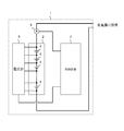
- FIG. 1 is a diagram illustrating an embodiment of a power storage device 1.
- the power storage device 1 shown in FIG. 1 may be mounted on a vehicle, for example, with a battery pack.
- the power storage device 1 measures the current flowing through the assembled battery 2, the assembled battery 2 having one or more batteries 4, the control circuit 3 that controls the power storage device 1, the voltmeter 5 that measures the voltage of the battery 4.
- An ammeter 6 is provided.
- the battery 4 is a secondary battery such as a lithium ion battery or a storage element.
- the control circuit 3 is a circuit that controls charging / discharging of the power storage device 1 and the battery 4, for example, a CPU (Central Processing Unit), a multi-core CPU, a programmable device (FPGA (Field Programmable Gate Array), a PLD (Programmable Logic Device), etc. ) Is conceivable.
- the control circuit 3 includes a storage unit provided inside or outside, and reads and executes a program for controlling each unit of the power storage device 1 stored in the storage unit. In this example, the control circuit 3 will be described. However, the control executed by the control circuit 3 may be performed by, for example, one or more ECUs (Electronic Control Unit) mounted on the vehicle. .
- control circuit 3 cancels the polarization after the discharge until the predetermined time T1 after the charging / discharging of the battery 4 is finished, and the charging / discharging of the battery 4 is completed and the polarization of the battery 4 is canceled.
- T2 or the polarization elimination time T3 after charging an estimated open circuit voltage OCV1 obtained by estimating the open circuit voltage after the polarization of the battery 4 is eliminated is obtained, and a first estimation is performed using the estimated open circuit voltage OCV1. Obtain the charging rate SOC1.
- the polarization elimination time T2 or T3 is a time for determining whether or not the polarization of the battery 4 has been eliminated, and is a time that can be considered that the polarization of the battery 4 has been eliminated. It can be considered that the polarization elimination time T2 or T3 is obtained by, for example, experiments or simulations. Since the polarization elimination time T2 or T3 varies depending on the temperature of the battery 4, it is desirable to change the polarization elimination time T2 or T3 according to the temperature. The polarization elimination times T2 and T3 may be determined based on the state of the battery 4. For example, the polarization elimination times T2 and T3 may be changed using the voltage of the battery 4, the current flowing through the assembled battery 2, the internal resistance, the temperature, and the like.
- the control circuit 3 performs the following process in order to obtain an accurate charging rate even after the charge / discharge is completed and before the polarization is eliminated.
- the control circuit 3 obtains a later-described reflection coefficient k corresponding to the estimated open circuit voltage OCV1.
- the control circuit 3 obtains a difference sub between the charging rate SOC0 obtained until the estimated open circuit voltage OCV1 is estimated and the first estimated charging rate SOC1.
- the control circuit 3 adds the charging rate SOC0 and a value obtained by multiplying the difference sub and the reflection coefficient k to obtain a second estimated charging rate SOC2 that is more accurate than the first estimated charging rate SOC1.
- the charging rate SOC0 obtained until the estimated open circuit voltage OCV1 is estimated is the charging rate obtained based on the current integration during charging / discharging or the closed circuit voltage.
- the charging rate SOC0 can be obtained from the charging rate before charging / discharging and the current integration during charging / discharging, or can be obtained from the SOC-OCV characteristic curve using the closed circuit voltage during charging / discharging, Alternatively, it can be obtained from the SOC-OCV characteristic curve using the open circuit voltage estimated from the closed circuit voltage during charging and discharging.
- charging / discharging also includes the end of charging / discharging.
- the method of obtaining the reflection coefficient k is, for example, a table in which the estimated open circuit voltage OCV1 stored in the storage unit, which is obtained based on the slope in the SOC-OCV characteristic curve of the battery 4, is associated with the reflection coefficient k.
- the reflection coefficient k corresponding to the estimated open circuit voltage OCV1 is obtained using an arithmetic expression.
- the SOC-OCV characteristic curve changes depending on the temperature of the battery 4, it is desirable to change the reflection coefficient k according to the temperature.
- the reflection coefficient k may be determined based on the state of the battery 4.
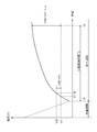
- FIG. 2A is a diagram showing an example of a change in voltage of the battery 4 during the discharge period and the polarization elimination time T2 after discharge.
- the vertical axis of FIG. 2A shows the voltage of the battery 4, and the horizontal axis shows time.
- the estimated open circuit voltage OCV1 is the difference between the voltage Vd1 at the first time t1 and the voltage Vd2 at the second time t2 after the first time t1 in a period shorter than the polarization elimination time T2.
- the amount of change (Vd2-Vd1) is obtained by using the voltage Vd1 at the first time t1 and the value obtained by multiplying the amount of change (Vd2-Vd1) by the estimation coefficient a for discharge. See Equation 1.
- OCV1 Vd1 + (Vd2 ⁇ Vd1) ⁇ a (Formula 1)
- the estimation coefficient a is updated based on the voltage measured after the polarization elimination time T2 has elapsed.
- the estimation coefficient a is updated using, for example, a highly accurate measurement open circuit voltage OCV2 measured after the polarization elimination time T2 has elapsed. That is, since the measured open circuit voltage OCV2 with high accuracy is depolarized, a new estimation coefficient a is obtained using the measured open circuit voltage OCV2 after depolarization. See Equation 2.
- the obtained estimation coefficient a is used when estimating the estimated open circuit voltage OCV1 after the next and subsequent discharges.
- the estimated open circuit voltage OCV1 is equal to the voltage Vd1 at the first time t1 (the voltage Vd1 measured at the first time t1) and the second time after the first time t1 in a period shorter than the polarization elimination time T2.
- a change amount (Vd2 ⁇ Vd1) is obtained using a difference from the voltage Vd2 at time t2 (voltage Vd2 measured at the second time t2), and the voltage Vd2 and change amount (Vd2 ⁇ Vd1) at the second time t2 are obtained.
- OCV1 Vd2 + (Vd2-Vd1) ⁇ a ′ (Formula 1 ′)
- the estimation coefficient a ′ is updated based on the voltage measured after the polarization elimination time T2 has elapsed.
- the estimation coefficient a ′ is updated using, for example, a highly accurate measured open circuit voltage OCV2 measured after the polarization elimination time T2 has elapsed. That is, since the measured open circuit voltage OCV2 with high accuracy is depolarized, a new estimation coefficient a ′ is obtained using the measured open circuit voltage OCV2 after depolarization. See Equation 2 ′.
- the obtained estimation coefficient a ′ is used when estimating the estimated open circuit voltage OCV1 after the next and subsequent discharges.
- OCV2 Vd2 + (Vd2-Vd1) ⁇ a ′ (Formula 2 ′) Further, the obtained estimation coefficient a or estimation coefficient a ′ may be changed using at least one of the temperature, the charging rate, and the deterioration level of the battery 4.
- the estimated open circuit voltage OCV1 is not obtained. That is, in the range where the charging rate of the battery 4 is low, the SOC-OCV characteristic curve of the battery 4 is different from the SOC specified value, so the estimated open circuit voltage OCV1 cannot be obtained with high accuracy. If the value is not within the value, the OCV may not be estimated.
- the estimated open circuit voltage OCV1 is not obtained for a predetermined time. That is, when the measured open circuit voltage OCV2 is measured after the polarization elimination time T2 has elapsed, it is considered that the predetermined time is high in the accuracy of the open circuit voltage calculated from the charge rate calculated by current integration, and thus newly estimated.
- the open circuit voltage OCV1 is not determined.
- the predetermined time may be one hour or more after obtaining the measured open circuit voltage OCV2, but is not limited to one hour.
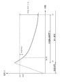
- FIG. 2B is a diagram illustrating an example of a change in the voltage of the battery 4 during the charging period and the polarization elimination time T3 after charging.
- the vertical axis of FIG. 2B shows the voltage of the battery 4, and the horizontal axis shows time.
- the charging of the battery 4 is completed at time t4 and the voltage Vc1 and the voltage Vc2 of the battery 4 are measured at the polarization elimination time T3 (time t4 to t7) after charging (when the predetermined time T1 ⁇ polarization elimination time T3), Based on the difference between the voltage Vc1 and the voltage Vc2 of the battery 4 measured by the predetermined time T1, that is, the change amount (Vc2 ⁇ Vc1), the estimated open circuit voltage OCV1 of the battery 4 after the polarization of the battery 4 is eliminated is obtained. .
- the measured voltage of the battery 4 is set as the measured open circuit voltage OCV2.
- the estimated open circuit voltage OCV1 is the difference between the voltage Vc1 at the first time t5 and the voltage Vc2 at the second time t6 after the first time t5 in a period shorter than the polarization elimination time T3.
- the amount of change (Vc2 ⁇ Vc1) is obtained, and the voltage Vc1 at the first time t5 is calculated by adding the value obtained by multiplying the amount of change (Vc2 ⁇ Vc1) by the charging estimation coefficient b. See Equation 3.
- OCV1 Vc1 + (Vc2-Vc1) ⁇ b (Formula 3)
- the estimation coefficient b is updated based on the voltage measured after the polarization elimination time T3 has elapsed.
- the estimation coefficient b is updated using, for example, a highly accurate measurement open circuit voltage OCV2 measured after the polarization elimination time T3 has elapsed. That is, since the measured open circuit voltage OCV2 with high accuracy is depolarized, a new estimation coefficient b is obtained using the measured open circuit voltage OCV2 after depolarization. See Equation 4. It is assumed that the obtained estimation coefficient b is used when estimating the estimated open circuit voltage OCV1 after the next and subsequent charging ends.
- the estimated open circuit voltage OCV1 is equal to the voltage Vc1 at the first time t5 (voltage Vc1 measured at the first time t5) and the second time after the first time t5 in a period shorter than the polarization elimination time T3.
- a change amount (Vc2-Vc1) is obtained using a difference from the voltage Vc2 at time t6 (voltage Vc2 measured at the second time t6), and the voltage Vc2 and change amount (Vc2-Vc1) at the second time t6 are obtained.
- the value obtained by multiplying the estimated coefficient b ′ for charging may be added. See Equation 3 ′.
- OCV1 Vc2 + (Vc2-Vc1) ⁇ b ′ (Formula 3 ′)
- the estimation coefficient b ′ is updated based on the voltage measured after the polarization elimination time T3 has elapsed.
- the estimation coefficient b ′ is updated using, for example, a highly accurate measurement open circuit voltage OCV2 measured after the polarization elimination time T3 has elapsed. That is, since the measured open circuit voltage OCV2 with high accuracy is depolarized, a new estimation coefficient b ′ is obtained using the measured open circuit voltage OCV2 after depolarization. See Equation 4 ′.
- the obtained estimation coefficient b ′ is used when estimating the estimated open circuit voltage OCV1 after the next and subsequent charging ends.
- OCV2 Vc2 + (Vc2-Vc1) ⁇ b ′ (Formula 4 ′) Further, the obtained estimation coefficient b or estimation coefficient b ′ may be changed using at least one of the temperature, the charging rate, and the deterioration degree of the battery 4.
- the estimated open circuit voltage OCV1 is not obtained. That is, in the range where the charging rate of the battery 4 is low, the OCV-SOC characteristic curve of the battery 4 is different from the SOC specified value, so the estimated open circuit voltage OCV1 cannot be obtained with high accuracy. If the value is not within the value, the OCV may not be estimated.
- the estimated open circuit voltage OCV1 is not obtained for a predetermined time. That is, when the measured open circuit voltage OCV2 is measured after the polarization elimination time T3 has elapsed, it is considered that the accuracy of the open circuit voltage calculated from the charging rate calculated by current integration is high for a predetermined time, and thus a new estimate is made.
- the open circuit voltage OCV1 is not determined.
- the predetermined time may be one hour or more after obtaining the measured open circuit voltage OCV2, but is not limited to one hour.
- the accurate estimated open circuit voltage OCV1 can be obtained even after the charging is finished and before the polarization is eliminated.
- the control circuit 3 performs charging / discharging of the battery 4 within a predetermined time T1 after the charging / discharging of the battery 4 is completed.
- the amount of change in the voltage of the battery 4 measured by the predetermined time T1 Based on this, an estimated open circuit voltage OCV1 obtained by estimating the open circuit voltage after the polarization of the battery 4 is eliminated is obtained, and the first estimated charging rate SOC1 is obtained using the estimated open circuit voltage OCV1.
- Control circuit 3 may be configured to estimate first estimated charging rate SOC1 by an estimation method other than the estimation method described using equations 1 to 4 or equations 1 ′ to 4 ′. .
- control circuit 3 obtains a voltage fluctuation curve based on the voltage detected by the voltmeter 5, estimates an estimated open circuit voltage OCV1 at the time of depolarization based on the obtained voltage fluctuation curve, and estimates the estimated open circuit. You may comprise so that the 1st estimated charging rate SOC1 at the time of the polarization elimination of the battery 4 may be estimated with the voltage OCV1.
- control circuit 3 estimates the estimated open circuit voltage OCV1 at the time of depolarization using a model of the battery 4 (e.g., an equivalent circuit model of the battery 4), and depolarizes the battery 4 using the estimated open circuit voltage OCV1.
- the first estimated charging rate SOC1 at the time may be estimated.
- the control circuit 3 performs the polarization elimination based on the voltage detected by the voltmeter 5 at the start of charging / discharging and the open circuit voltage corresponding to the charging rate obtained from the current integrated value of the battery 4 being charged / discharged.
- the estimated open circuit voltage OCV1 may be estimated, and the first estimated charge rate SOC1 when the polarization of the battery 4 is eliminated may be estimated based on the estimated open circuit voltage OCV1.
- C The estimation of the first estimated charging rate SOC1 will be described.
- the control circuit 3 obtains the first estimated charging rate SOC1 using the estimated open circuit voltage OCV1.
- the first estimated charging rate SOC1 corresponding to the estimated open circuit voltage OCV1 is obtained using the SOC-OCV characteristic curve of the battery 4.
- the estimated accuracy of the first estimated charging rate SOC1 is lowered depending on the value of the estimated open circuit voltage OCV1.
- FIG. 3 is a diagram showing an example of the SOC-OCV characteristic curve of the battery 4.
- the vertical axis of FIG. 3 shows the open circuit voltage of the battery 4, and the horizontal axis shows the charging rate.
- the first estimated charging rate SOC1 is set based on the estimated open circuit voltage Vd3.
- the first estimated charging rate SOC1 also includes an estimation error (charging rate ⁇ SOC1) corresponding to the voltage ⁇ OCV.
- the first estimated charge rate SOC1 is estimated by estimating the first estimated charge rate SOC1 based on the estimated open circuit voltage Vd4.
- the SOC1 also includes an estimation error of the charging rate ⁇ SOC2 corresponding to the voltage ⁇ OCV.
- the region where the SOC-OCV characteristic curve of the battery 4 is large that is, the open circuit voltage shown in FIG.
- the SOC-OCV of the battery 4 is compared with the case where the estimation is performed in a region where the change amount of the charge rate is small relative to the change amount (voltage range OCVb other than the predetermined voltage range OCVs or charge rate range SOCb other than the predetermined charge rate range SOCs).
- a region where the change rate of the charging rate is large relative to the change amount of the open circuit voltage shown in FIG. 3 (predetermined voltage range OCVs or predetermined charge rate range SOCs)
- the estimation accuracy decreases.
- the second estimated charging rate SOC2 is calculated using the charging rate SOC0 obtained based on the circuit voltage, the first estimated charging rate SOC1, and the reflection coefficient k obtained according to the slope of the SOC-OCV characteristic curve. The decrease in the estimation accuracy of the obtained and estimated charging rate is suppressed.
- the first estimated charging rate SOC1 is divided into a case where it is included in the charging rate range SOCb corresponding to the voltage range OCVb and a case where it is included in the predetermined charging rate range SOCs corresponding to the predetermined voltage range OCVs.
- the second estimated charging rate SOC2 may be obtained using the reflection coefficient k.
- the second estimated charging rate SOC2 is obtained as a reflection coefficient k corresponding to the estimated open circuit voltage OCV1 or the first estimated charging rate SOC1, and the difference between the charging rate SOC0 and the first estimated charging rate SOC1 (SOC1-SOC0) Is added to the charge rate SOC0 obtained until the estimated open circuit voltage OCV1 is estimated, and the difference (SOC1-SOC0) multiplied by the reflection coefficient k to obtain the second estimated charge rate SOC2. . See Equation 5.
- the reflection coefficient k is a numerical value of 0 or more and 1 or less.
- the estimated open circuit voltage OCV1 stored in the storage unit is associated with the reflection coefficient k using the estimated open circuit voltage OCV1 or the first estimated charge rate SOC1.
- the reflection coefficient k is obtained using the obtained table or arithmetic expression.
- the reflection coefficient k is the first reflection coefficient k1
- the estimated open circuit voltage OCV1 is the predetermined voltage.
- the reflection coefficient k is set to a second reflection coefficient k2 that is larger than the first reflection coefficient k1.
- the reflection coefficient k is set as the first reflection coefficient k1.
- the reflection coefficient k is set to a second reflection coefficient k2 that is larger than the first reflection coefficient k1.
- the reflection coefficient k may be a constant value only in a flat region.
- the reflection coefficient k may be changed as appropriate according to the estimated open circuit voltage OCV1 or the first estimated charging rate SOC1.
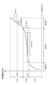
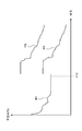
- FIG. 4 is a diagram illustrating an example of the first estimated charging rate SOC1 and the second estimated charging rate SOC2.
- the vertical axis of FIG. 4 shows the charging rate of the battery 4, and the horizontal axis shows time.
- a curve 401 indicates the charging rate SOC0 obtained based on the current integration during charging / discharging or the closed circuit voltage.
- a curve 402 represents a first estimated charging rate SOC1 with respect to an estimated open circuit voltage OCV1 in a flat region after the completion of charging / discharging.
- a curve 403 indicates the second estimated charging rate SOC2 obtained based on the estimated open circuit voltage OCV1 or the first estimated charging rate SOC1 in a flat region after the completion of charging / discharging.
- the charging rate SOC0 obtained at time t7 before estimating the estimated open circuit voltage OCV1 or the estimated open circuit voltage OCV1 obtained at time t8 after the completion of charging / discharging is SOC ⁇
- the voltage ⁇ OCV is included as an estimation error in a flat region in the OCV characteristic curve.
- a first estimated charging rate SOC1 in which ⁇ SOC1 is included in the charging rate is obtained as an estimation error.
- the estimation error ⁇ SOC with respect to the estimation error ⁇ OCV is large, so that the estimation accuracy of the first estimated charging rate SOC1 is low.
- the reflection coefficient k is reduced and the first estimated charging rate SOC1 is corrected to the second estimated charging rate SOC2, it is possible to prevent the estimated charging rate from deviating greatly from the actual charging rate. . That is, the second estimated charging rate SOC2 can be closer to the charging rate SOC0 than the first estimated charging rate SOC1.
- the estimation error ⁇ SOC with respect to the estimation error ⁇ OCV is small, so that the estimation accuracy of the first estimated charging rate SOC1 is not lowered. Therefore, by increasing the reflection coefficient k, the second estimated charging rate SOC2 can be brought close to the actual charging rate.
- the second value is set so that the difference becomes smaller than the predetermined value.
- the estimated charging rate SOC2 may be changed. By controlling in this way, it is possible to prevent the estimated charging rate from deviating greatly from the actual charging rate.
- the predetermined value is, for example, a value for determining whether or not the second estimated charging rate SOC2 obtained at time t8 is within a range considered to be correct with respect to the charging rate SOC0 obtained at time t7. It is obtained by simulation.
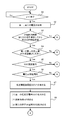
- step S1 is a diagram showing an embodiment of the operation of the power storage device.
- the control circuit 3 determines whether or not the vehicle has finished running or charging (the discharging period in FIG. 2A, the charging period in FIG. 2B) in step S1 in FIG. If it is determined that the vehicle has finished running or charging (pause period in FIGS. 2A and 2B) (Yes), the process proceeds to step S2, and if running or charged (No), the process proceeds to step S1. stand by. That is, in step S1, it is determined whether charging / discharging has ended.
- step S2 the control circuit 3 acquires the first voltage and the second voltage. After the discharge, the voltage Vd1 at the first time t1 and the voltage Vd2 at the second time t2 after the first time in FIG. 2A are acquired. If it is after charging, the voltage Vc1 at the first time t5 and the voltage Vc2 at the second time t6 after the first time in FIG. 2B are acquired.
- step S3 whether or not a predetermined time has elapsed since the measurement of the measured open circuit voltage OCV2 after the control circuit 3 passed the polarization elimination time (polarization elimination time T2 after discharge or polarization elimination time T3 after charging) Determine whether or not.
- the predetermined time has elapsed (Yes)
- the process proceeds to step S4, and when the predetermined time has not elapsed (No), this process is terminated.
- the predetermined time is estimated using the estimated open circuit voltage OCV1 with high accuracy of the open circuit voltage calculated from the charge rate calculated by current integration. Since it is considered that the accuracy of the charging rate calculated by the current integration is higher than the first estimated charging rate SOC1, the estimated open circuit voltage OCV1 is not newly estimated.
- the predetermined time may be, for example, one hour or more, but is not particularly limited.
- step S4 the control circuit 3 determines whether or not the difference between the first voltage and the second voltage is greater than a predetermined value, for example, the measurement error Ver. If the difference is greater than the measurement error Ver (Yes), step S5 is performed. If the measurement error is equal to or smaller than Ver (No), the first voltage and the second voltage are not changed, and thus this process is terminated. For example, in the rest period after discharge, if Vd2 ⁇ Vd1> Ver, the process proceeds to step S5. In the case of a rest period after charging, if Vc1-Vc2> Ver, the process proceeds to step S5.
- a predetermined value for example, the measurement error Ver.
- step S5 the control circuit 3 determines whether or not the current charging rate SOC of the battery 4 is within a predetermined range (within the SOC specified value). If it is within the SOC specified value (Yes), the process proceeds to step S6. If it is not within the SOC specified value (No), this process is terminated. In the range where the charging rate of the battery 4 is low, the OCV-SOC characteristic curve of the battery 4 is different from the SOC specified value, so the estimated open circuit voltage OCV1 cannot be accurately estimated. If it is not within the value, this process is terminated.
- step S6 it is determined whether or not the voltage measured by the control circuit 3 is in a normal range (normal voltage range). If the voltage is within the normal voltage range (Yes), the process proceeds to step S7, where If not (No), this process ends.
- step S6 when the voltage cannot be measured normally due to noise or the like, if the measured voltage is used, an accurate open circuit voltage cannot be obtained. Therefore, when there is a measured voltage affected by noise or the like. Terminates this process.
- the voltage Vd3 is measured before the first time t1, the voltage Vd4 is measured before the second time t2, and
- the voltage Vc3 is measured before time t1, the voltage Vc4 is measured before time t2, and
- step S7 in a period shorter than the polarization elimination time, the amount of change is obtained using the difference between the voltage at the first time t1 and the voltage at the second time t2 after the first time, and at the first time t1.
- the control circuit 3 obtains the estimated open circuit voltage OCV1 by adding the voltage and the value obtained by multiplying the change amount by the estimation coefficient.
- step S8 the control circuit 3 performs the following processes (1) to (3) in order to obtain an accurate charging rate.
- First estimated charging rate SOC1 is obtained using estimated open circuit voltage OCV1.
- the reflection coefficient k is a numerical value of 0 or more and 1 or less.
- the estimated open circuit voltage OCV1 stored in the storage unit is associated with the reflection coefficient k using the estimated open circuit voltage OCV1 or the first estimated charge rate SOC1.
- the reflection coefficient k is obtained using the obtained table or the table in which the first estimated charging rate SOC1 and the reflection coefficient k are associated.
- the estimated open circuit voltage OCV1 is a predetermined voltage range OCVs (a range corresponding to a flat region in the SOC-OCV characteristic curve of FIG. 3)
- the reflection coefficient k is set as the first reflection coefficient k1
- the reflection coefficient k is set to a second reflection coefficient k2 larger than the first reflection coefficient k1.
- the reflection coefficient k is reflected to the first reflection rate k.
- the coefficient k1 is set and the first estimated charging rate SOC1 with respect to the estimated open circuit voltage OCV1 is other than the predetermined charging rate range SOCs (charging rate range SOCb)
- the reflection coefficient k is a second reflection coefficient larger than the first reflection coefficient k1.
- the control circuit 3 obtains a difference between the charging rate SOC0 and the first estimated charging rate SOC1, and adds a value obtained by multiplying the obtained charging rate SOC1 by the difference and a reflection coefficient to obtain a second estimated charging rate.
- step S8 By performing the control shown in step S8, an accurate estimated charging rate can be obtained even after the charge / discharge is completed and before the polarization is eliminated.
- the reflection coefficient k may be a constant value only in a flat region.
- the reflection coefficient k may be changed as appropriate according to the estimated open circuit voltage OCV1 or the first estimated charging rate SOC1. Further, when the difference between the charging rate SOC0 obtained until the estimated open circuit voltage OCV1 is estimated and the second estimated charging rate SOC2 is a predetermined value or more, the second value is set so that the difference becomes smaller than the predetermined value.
- the estimated charging rate SOC2 may be changed. By controlling in this way, it is possible to prevent the estimated charging rate from deviating greatly from the actual charging rate.
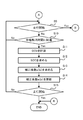
- step S9 in FIG. 6 the control circuit 3 determines whether or not the vehicle has started traveling. If the vehicle has not started traveling (No), the process proceeds to step S10, and when traveling has started (Yes). This process ends.
- step S10 the control circuit 3 proceeds to step S11 when the polarization elimination time is reached (Yes), and proceeds to step S9 when the polarization elimination time is not reached (No).
- step S11 the control circuit 3 measures the measured open circuit voltage OCV2, and in step S12, obtains the charging rate using the measured open circuit voltage OCV2.
- the control circuit 3 measures the measured open circuit voltage OCV2, and in step S12, obtains the charging rate using the measured open circuit voltage OCV2.
- step S13 the control circuit 3 obtains a correction coefficient, and in step S14, the correction coefficient is updated.
- the estimation coefficient a or the estimation coefficient a ′ for discharging is updated based on the voltage measured after the polarization elimination time T2 has elapsed.
- the charging estimation coefficient b or the estimation coefficient b ′ is updated based on the voltage measured after the polarization elimination time T3 has elapsed.
- the estimation coefficient may be obtained by weighting with a moving average or the like.
- step S15 the control circuit 3 determines whether or not the vehicle has started traveling. If the vehicle has not started traveling (No), the process proceeds to step S9, and if the vehicle has started traveling (Yes), this control circuit 3 The process ends. Note that steps S13 and S14 may be performed after step S15.
- the first estimated charging rate SOC1 with good estimation accuracy can be obtained even after the charge / discharge is completed and before the polarization is eliminated. Further, by estimating the charging rate using the charging rate SOC0, the reflection coefficient k, and the first estimated charging rate SOC1, the second estimated charging rate with better estimation accuracy than the first estimated charging rate SOC1. SOC2 can be determined. Further, by using the reflection coefficient k obtained according to the slope of the OC-OCV characteristic curve (in other words, the range of the estimated open circuit voltage OCV1 or the range of the first estimated charging rate SOC1), the estimation accuracy is further improved. The second estimated charging rate SOC2 can be obtained.
Landscapes
- Engineering & Computer Science (AREA)
- Physics & Mathematics (AREA)
- General Physics & Mathematics (AREA)
- Manufacturing & Machinery (AREA)
- Chemical & Material Sciences (AREA)
- Chemical Kinetics & Catalysis (AREA)
- Electrochemistry (AREA)
- General Chemical & Material Sciences (AREA)
- Power Engineering (AREA)
- Secondary Cells (AREA)
- Tests Of Electric Status Of Batteries (AREA)
- Charge And Discharge Circuits For Batteries Or The Like (AREA)
Abstract
電池4と、電池4の充放電を制御する制御回路3と、を備える蓄電装置1であって、制御回路3は、電池4の充放電が終了してからの所定時間が、電池4の充放電が終了して電池4の分極が解消したと見做すまでの分極解消時間より短い場合、電池4の分極が解消した後の電池4の推定開回路電圧を求め、推定開回路電圧を用いて第一の推定充電率を求め、推定開回路電圧に基づいて反映係数を求め、推定開回路電圧を推定するまでに求めた充電率と、第一の推定充電率との差を求め、推定開回路電圧を推定するまでに求めた充電率と、差と反映係数とを乗算した値とを加算して第二の推定充電率を求める蓄電装置1である。
Description
本発明は、充放電をする蓄電装置及び蓄電装置の制御方法に関する。
電池が充放電を終了した後まだ分極の影響がある場合、計測した電池の電圧推移から分極が解消したときの開回路電圧(OCV:Open Circuit Voltage)を推定し、推定した開回路電圧を用いて電池のSOC-OCV特性曲線に基づいて充電率(SOC:State Of Charge)を推定する技術が知られている。
関連する技術として、特許文献1及び特許文献2などの技術がある。
しかしながら、推定した開回路電圧を用いて推定充電率を求める場合、電池のSOC-OCV特性曲線の傾きが大きい領域(開回路電圧の変化量に対して充電率の変化量が小さい領域)で推定充電率を求める場合より、傾きが小さい領域(開回路電圧の変化量に対して充電率の変化量が大きい領域)で推定充電率を求める場合の方が、電圧の計測値誤差などの影響を受けて、推定充電率と実際の充電率との差が大きくなりやすいため、充電率の推定精度が低下する。
本発明の一側面に係る目的は、充放電を終了した後に、分極が解消する前でも、精度のよい推定充電率を求めることができる蓄電装置及び蓄電装置の制御方法を提供することである。
実施の態様の一つである蓄電装置は電池と電池の充放電を制御する制御回路とを備える。
制御回路は、電池の充放電が終了してからの所定時間が、電池の充放電が終了して電池の分極が解消したと見做すまでの分極解消時間より短い場合、電池の分極が解消した後の推定開回路電圧を求め、その推定開回路電圧を用いて第一の推定充電率を求める。続いて、制御回路は、推定開回路電圧に対応する反映係数を求め、推定開回路電圧を推定するまでに求めた充電率と、第一の推定充電率との差を求める。続いて、制御回路は、推定開回路電圧を推定するまでに求めた充電率と、その差と反映係数とを乗算した値と、を加算して第二の推定充電率を求める。
充放電を終了した後に、分極が解消する前でも、精度のよい推定充電率を求めることができる。
以下図面に基づいて実施形態について詳細を説明する。
図1は、蓄電装置1の一実施例を示す図である。図1に示す蓄電装置1は、例えば電池パックで、車両に搭載することが考えられる。本例において蓄電装置1は、一つ以上の電池4を有する組電池2、蓄電装置1を制御する制御回路3、電池4の電圧を計測する電圧計5、組電池2に流れる電流を計測する電流計6を有している。電池4はリチウムイオン電池などの二次電池又は蓄電素子などである。
制御回路3は蓄電装置1及び電池4の充放電を制御する回路で、例えば、CPU(Central Processing Unit)、マルチコアCPU、プログラマブルなデバイス(FPGA(Field Programmable Gate Array)やPLD(Programmable Logic Device)など)を用いた回路が考えられる。また、制御回路3は、内部又は外部に備えられている記憶部を備え、記憶部に記憶されている蓄電装置1の各部を制御するプログラムを読み出して実行する。なお、本例においては制御回路3を用いて説明をするが、制御回路3が実行する制御を、例えば車両に搭載されている一つ以上のECU(Electronic Control Unit)などに行わせてもよい。
また、制御回路3は、電池4の充放電が終了してからの所定時間T1が、電池4の充放電が終了して電池4の分極が解消したと見做すまでの放電後の分極解消時間T2あるいは充電後の分極解消時間T3より短い場合、電池4の分極が解消した後の開回路電圧を推定した推定開回路電圧OCV1を求め、その推定開回路電圧OCV1を用いて第一の推定充電率SOC1を求める。
ここで、分極解消時間T2あるいはT3は電池4の分極が解消したか否かを判定する時間で、電池4の分極が解消したと見做せる時間である。分極解消時間T2あるいはT3は、例えば、実験やシミュレーションにより求めることが考えられる。なお、分極解消時間T2あるいはT3は、電池4の温度により変化するので、温度に応じて分極解消時間T2あるいはT3を変えることが望ましい。また、分極解消時間T2、T3は電池4の状態に基づいて決めてもよい。例えば、電池4の電圧、組電池2に流れる電流、内部抵抗、温度などを用いて分極解消時間T2、T3の時間を変更してもよい。
続いて、制御回路3は、充放電を終了した後に、分極が解消する前でも、精度のよい充電率を求めるために次の処理を実施する。制御回路3は、推定開回路電圧OCV1に対応する後述する反映係数kを求める。続いて、制御回路3は、推定開回路電圧OCV1を推定するまでに求めた充電率SOC0と、第一の推定充電率SOC1との差subを求める。続いて、制御回路3は、充電率SOC0と、差subと反映係数kとを乗算した値とを加算し、第一の推定充電率SOC1より精度のよい第二の推定充電率SOC2を求める。
ここで、推定開回路電圧OCV1を推定するまでに求めた充電率SOC0とは、充放電中の電流積算あるいは閉回路電圧に基づいて求めた充電率である。例えば、充電率SOC0は、充放電前の充電率と充放電中の電流積算とから求めることができ、あるいは、充放電中の閉回路電圧を用いてSOC-OCV特性曲線から求めることができ、あるいは、充放電中の閉回路電圧から推定した開回路電圧を用いてSOC-OCV特性曲線から求めることができる。なお、充放電中とは充放電終了時も含まれる。
また、反映係数kを求める方法は、例えば、電池4のSOC-OCV特性曲線における傾きに基づいて求めた、記憶部に記憶されている推定開回路電圧OCV1と反映係数kとが関連付けられたテーブルあるいは演算式を用いて、推定開回路電圧OCV1に対応する反映係数kを求める。また、SOC-OCV特性曲線は電池4の温度により変化するので、温度に応じて反映係数kを変えることが望ましい。また、反映係数kは電池4の状態に基づいて決めてもよい。
(A)放電が終了してからの推定開回路電圧OCV1の推定の一例について説明する。
(A)放電が終了してからの推定開回路電圧OCV1の推定の一例について説明する。
図2Aは、放電期間及び放電後の分極解消時間T2の電池4の電圧の変化の一例を示す図である。図2Aの縦軸には電池4の電圧が示され、横軸には時間が示されている。
時間t0において電池4の放電が終了し、放電後の分極解消時間T2(時間t0からt3)において電池4の電圧Vd1と電圧Vd2を計測した場合(所定時間T1<分極解消時間T2の場合)、所定時間T1までに計測した電池4の電圧Vd1と電圧Vd2との差、すなわち変化量(Vd2-Vd1)に基づいて、電池4の分極が解消した後の電池4の推定開回路電圧OCV1を求める。なお、分極解消時間T2を経過した後に計測した場合(所定時間T1≧分極解消時間T2の場合)は、電池4の計測した電圧を計測開回路電圧OCV2とする。
推定開回路電圧OCV1は、図2Aの例では、分極解消時間T2より短い期間における、第一の時間t1の電圧Vd1と第一の時間t1以降の第二の時間t2の電圧Vd2との差を用いて変化量(Vd2-Vd1)を求め、第一の時間t1の電圧Vd1と、変化量(Vd2-Vd1)に放電用の推定係数aを乗算した値と、を加算して求める。式1を参照。
OCV1=Vd1+(Vd2-Vd1)×a (式1)
推定係数aは、分極解消時間T2を経過した後に計測した電圧に基づいて更新する。推定係数aは、例えば、分極解消時間T2を経過した後に計測した精度の高い計測開回路電圧OCV2を用いて更新する。すなわち、計測した精度の高い計測開回路電圧OCV2は分極が解消しているので、分極が解消した後の計測開回路電圧OCV2を用いて新しい推定係数aを求める。式2を参照。その求めた推定係数aは、次回以降の放電終了後の推定開回路電圧OCV1の推定時に使用されるものとする。
推定係数aは、分極解消時間T2を経過した後に計測した電圧に基づいて更新する。推定係数aは、例えば、分極解消時間T2を経過した後に計測した精度の高い計測開回路電圧OCV2を用いて更新する。すなわち、計測した精度の高い計測開回路電圧OCV2は分極が解消しているので、分極が解消した後の計測開回路電圧OCV2を用いて新しい推定係数aを求める。式2を参照。その求めた推定係数aは、次回以降の放電終了後の推定開回路電圧OCV1の推定時に使用されるものとする。
OCV2=Vd1+(Vd2-Vd1)×a (式2)
または、推定開回路電圧OCV1は、分極解消時間T2より短い期間における、第一の時間t1の電圧Vd1(第一の時間t1において計測された電圧Vd1)と第一の時間t1以降の第二の時間t2の電圧Vd2(第二の時間t2において計測された電圧Vd2)との差を用いて変化量(Vd2-Vd1)を求め、第二の時間t2の電圧Vd2と、変化量(Vd2-Vd1)に放電用の推定係数a´を乗算した値と、を加算して求めてもよい。式1´を参照。
または、推定開回路電圧OCV1は、分極解消時間T2より短い期間における、第一の時間t1の電圧Vd1(第一の時間t1において計測された電圧Vd1)と第一の時間t1以降の第二の時間t2の電圧Vd2(第二の時間t2において計測された電圧Vd2)との差を用いて変化量(Vd2-Vd1)を求め、第二の時間t2の電圧Vd2と、変化量(Vd2-Vd1)に放電用の推定係数a´を乗算した値と、を加算して求めてもよい。式1´を参照。
OCV1=Vd2+(Vd2-Vd1)×a´ (式1´)
推定係数a´は、分極解消時間T2を経過した後に計測した電圧に基づいて更新する。推定係数a´は、例えば、分極解消時間T2を経過した後に計測した精度の高い計測開回路電圧OCV2を用いて更新する。すなわち、計測した精度の高い計測開回路電圧OCV2は分極が解消しているので、分極が解消した後の計測開回路電圧OCV2を用いて新しい推定係数a´を求める。式2´を参照。その求めた推定係数a´は、次回以降の放電終了後の推定開回路電圧OCV1の推定時に使用されるものとする。
推定係数a´は、分極解消時間T2を経過した後に計測した電圧に基づいて更新する。推定係数a´は、例えば、分極解消時間T2を経過した後に計測した精度の高い計測開回路電圧OCV2を用いて更新する。すなわち、計測した精度の高い計測開回路電圧OCV2は分極が解消しているので、分極が解消した後の計測開回路電圧OCV2を用いて新しい推定係数a´を求める。式2´を参照。その求めた推定係数a´は、次回以降の放電終了後の推定開回路電圧OCV1の推定時に使用されるものとする。
OCV2=Vd2+(Vd2-Vd1)×a´ (式2´)
また、求めた推定係数aまたは推定係数a´は、電池4の温度、充電率、及び劣化度の少なくとも1つを用いて変更してもよい。
また、求めた推定係数aまたは推定係数a´は、電池4の温度、充電率、及び劣化度の少なくとも1つを用いて変更してもよい。
なお、電池4の現在の充電率SOCが所定範囲(SOC規定値内)にない場合には推定開回路電圧OCV1を求めない。すなわち、電池4の充電率が低い範囲などでは、電池4のSOC-OCV特性曲線においてSOC規定値内と変化が異なるので、精度よく推定開回路電圧OCV1が求められないため、電池4のSOC規定値内にない場合にはOCVの推定を行わないようにしてもよい。
更に、分極解消時間T2を経過した後に計測開回路電圧OCV2を計測した場合、所定の時間は推定開回路電圧OCV1を求めない。すなわち、分極解消時間T2を経過した後に計測開回路電圧OCV2を計測した場合、所定の時間は、電流積算で算出した充電率から算出した開回路電圧の精度が高いと考えられるため、新たに推定開回路電圧OCV1を求めないようにする。所定の時間は、例えば、計測開回路電圧OCV2を求めてから一時間以上が考えられるが、一時間に限定されるものではない。
上記のように推定開回路電圧OCV1を求めることで、放電を終了した後に、分極が解消する前でも、精度のよい推定開回路電圧OCV1を求めることができる。
(B)充電が終了してからの推定開回路電圧OCV1の推定の一例について説明する。
(B)充電が終了してからの推定開回路電圧OCV1の推定の一例について説明する。
図2Bは、充電期間及び充電後の分極解消時間T3の電池4の電圧の変化の一例を示す図である。図2Bの縦軸には電池4の電圧が示され、横軸には時間が示されている。
時間t4において電池4の充電が終了し、充電後の分極解消時間T3(時間t4からt7)において電池4の電圧Vc1と電圧Vc2を計測した場合(所定時間T1<分極解消時間T3の場合)、所定時間T1までに計測した電池4の電圧Vc1と電圧Vc2との差、すなわち変化量(Vc2-Vc1)に基づいて、電池4の分極が解消した後の電池4の推定開回路電圧OCV1を求める。なお、分極解消時間T3を経過した後に計測した場合(所定時間T1≧分極解消時間T3の場合)は、電池4の計測した電圧を計測開回路電圧OCV2とする。
推定開回路電圧OCV1は、図2Bの例では、分極解消時間T3より短い期間における、第一の時間t5の電圧Vc1と第一の時間t5以降の第二の時間t6の電圧Vc2との差を用いて変化量(Vc2-Vc1)を求め、第一の時間t5の電圧Vc1と、変化量(Vc2-Vc1)に充電用の推定係数bを乗算した値と、を加算して算出する。式3を参照。
OCV1=Vc1+(Vc2-Vc1)×b (式3)
推定係数bは、分極解消時間T3を経過した後に計測した電圧に基づいて更新する。推定係数bは、例えば、分極解消時間T3を経過した後に計測した精度の高い計測開回路電圧OCV2を用いて更新する。すなわち、計測した精度の高い計測開回路電圧OCV2は分極が解消しているので、分極が解消した後の計測開回路電圧OCV2を用いて新しい推定係数bを求める。式4を参照。その求めた推定係数bは、次回以降の充電終了後の推定開回路電圧OCV1の推定時に使用されるものとする。
推定係数bは、分極解消時間T3を経過した後に計測した電圧に基づいて更新する。推定係数bは、例えば、分極解消時間T3を経過した後に計測した精度の高い計測開回路電圧OCV2を用いて更新する。すなわち、計測した精度の高い計測開回路電圧OCV2は分極が解消しているので、分極が解消した後の計測開回路電圧OCV2を用いて新しい推定係数bを求める。式4を参照。その求めた推定係数bは、次回以降の充電終了後の推定開回路電圧OCV1の推定時に使用されるものとする。
OCV2=Vc1+(Vc2-Vc1)×b (式4)
または、推定開回路電圧OCV1は、分極解消時間T3より短い期間における、第一の時間t5の電圧Vc1(第一の時間t5において計測された電圧Vc1)と第一の時間t5以降の第二の時間t6の電圧Vc2(第二の時間t6において計測された電圧Vc2)との差を用いて変化量(Vc2-Vc1)を求め、第二の時間t6の電圧Vc2と、変化量(Vc2-Vc1)に充電用の推定係数b´を乗算した値と、を加算して求めてもよい。式3´を参照。
または、推定開回路電圧OCV1は、分極解消時間T3より短い期間における、第一の時間t5の電圧Vc1(第一の時間t5において計測された電圧Vc1)と第一の時間t5以降の第二の時間t6の電圧Vc2(第二の時間t6において計測された電圧Vc2)との差を用いて変化量(Vc2-Vc1)を求め、第二の時間t6の電圧Vc2と、変化量(Vc2-Vc1)に充電用の推定係数b´を乗算した値と、を加算して求めてもよい。式3´を参照。
OCV1=Vc2+(Vc2-Vc1)×b´ (式3´)
推定係数b´は、分極解消時間T3を経過した後に計測した電圧に基づいて更新する。推定係数b´は、例えば、分極解消時間T3を経過した後に計測した精度の高い計測開回路電圧OCV2を用いて更新する。すなわち、計測した精度の高い計測開回路電圧OCV2は分極が解消しているので、分極が解消した後の計測開回路電圧OCV2を用いて新しい推定係数b´を求める。式4´を参照。その求めた推定係数b´は、次回以降の充電終了後の推定開回路電圧OCV1の推定時に使用されるものとする。
推定係数b´は、分極解消時間T3を経過した後に計測した電圧に基づいて更新する。推定係数b´は、例えば、分極解消時間T3を経過した後に計測した精度の高い計測開回路電圧OCV2を用いて更新する。すなわち、計測した精度の高い計測開回路電圧OCV2は分極が解消しているので、分極が解消した後の計測開回路電圧OCV2を用いて新しい推定係数b´を求める。式4´を参照。その求めた推定係数b´は、次回以降の充電終了後の推定開回路電圧OCV1の推定時に使用されるものとする。
OCV2=Vc2+(Vc2-Vc1)×b´ (式4´)
また、求めた推定係数bまたは推定係数b´は、電池4の温度、充電率、及び劣化度の少なくとも1つを用いて変更してもよい。
また、求めた推定係数bまたは推定係数b´は、電池4の温度、充電率、及び劣化度の少なくとも1つを用いて変更してもよい。
なお、電池4の現在の充電率SOCが所定範囲(SOC規定値内)にない場合には推定開回路電圧OCV1を求めない。すなわち、電池4の充電率が低い範囲などでは、電池4のOCV-SOC特性曲線においてSOC規定値内と変化が異なるので、精度よく推定開回路電圧OCV1が求められないため、電池4のSOC規定値内にない場合にはOCVの推定を行わないようにしてもよい。
更に、分極解消時間T3を経過した後に計測開回路電圧OCV2を計測した場合、所定の時間は推定開回路電圧OCV1を求めない。すなわち、分極解消時間T3を経過した後に計測開回路電圧OCV2を計測した場合、所定の時間は、電流積算で算出した充電率から算出した開回路電圧の精度が高いと考えられるため、新たに推定開回路電圧OCV1を求めないようにする。所定の時間は、例えば、計測開回路電圧OCV2を求めてから一時間以上が考えられるが、一時間に限定されるものではない。
上記のように推定開回路電圧OCV1を求めることで、充電を終了した後に、分極が解消する前でも、精度のよい推定開回路電圧OCV1を求めることができる。
式1~式4または式1´~式4´を用いて説明したように、例えば、制御回路3は、電池4の充放電が終了してからの所定時間T1が、電池4の充放電が終了して電池4の分極が解消したと見做すまでの放電後の分極解消時間T2あるいは充電後の分極解消時間T3より短い場合、所定時間T1までに計測した電池4の電圧の変化量に基づいて、電池4の分極が解消した後の開回路電圧を推定した推定開回路電圧OCV1を求め、その推定開回路電圧OCV1を用いて第一の推定充電率SOC1を求める。
なお、制御回路3は、式1~式4または式1´~式4´を用いて説明した推定方法以外の推定方法により、第一の推定充電率SOC1を推定するように構成してもよい。
例えば、制御回路3は、電圧計5により検出される電圧により電圧変動曲線を求め、その求めた電圧変動曲線に基づいて分極解消時の推定開回路電圧OCV1を推定し、その推定した推定開回路電圧OCV1により電池4の分極解消時の第一の推定充電率SOC1を推定するように構成してもよい。
例えば、制御回路3は、電池4のモデル(電池4の等価回路モデルなど)を用いて分極解消時の推定開回路電圧OCV1を推定し、その推定した推定開回路電圧OCV1により電池4の分極解消時の第一の推定充電率SOC1を推定するように構成してもよい。
例えば、制御回路3は、充放電開始時に電圧計5により検出される電圧と、充放電中の電池4の電流積算値により求められる充電率に対応する開回路電圧とに基づいて、分極解消時の推定開回路電圧OCV1を推定し、その推定した推定開回路電圧OCV1により電池4の分極解消時の第一の推定充電率SOC1を推定するように構成してもよい。
(C)第一の推定充電率SOC1の推定について説明する。
(C)第一の推定充電率SOC1の推定について説明する。
制御回路3は、所定時間T1が分極解消時間T2またはT3より短い場合、推定開回路電圧OCV1を用いて第一の推定充電率SOC1を求める。例えば、電池4のSOC-OCV特性曲線を用いて、推定開回路電圧OCV1に対応する第一の推定充電率SOC1を求める。このように推定開回路電圧OCV1を用いて第一の推定充電率SOC1を推定することで、充放電を終了した後に、分極が解消する前でも、精度のよい第一の推定充電率SOC1を求めることができる。
また、所定時間T1が分極解消時間T2あるいはT3以上長い場合、計測した計測開回路電圧OCV2を用いて充電率を求める。
(D)第二の推定充電率SOC2の推定について説明する。
(D)第二の推定充電率SOC2の推定について説明する。
推定開回路電圧OCV1に推定誤差が含まれている場合、推定開回路電圧OCV1の値によって第一の推定充電率SOC1の推定精度が低下する。
図3は、電池4のSOC-OCV特性曲線の一例を示す図である。図3の縦軸には電池4の開回路電圧が示され、横軸には充電率が示されている。例えば、図3に示すように開回路電圧範囲OCVs内の推定開回路電圧Vd3に推定誤差(電圧ΔOCV)が含まれている場合、推定開回路電圧Vd3に基づいて第一の推定充電率SOC1を推定すると、第一の推定充電率SOC1にも電圧ΔOCVに対応する推定誤差(充電率ΔSOC1)を含むことになる。また、開回路電圧範囲OCVb内の推定開回路電圧Vd4に推定誤差(電圧ΔOCV)がある場合、推定開回路電圧Vd4に基づいて第一の推定充電率SOC1を推定すると、第一の推定充電率SOC1にも電圧ΔOCVに対応する充電率ΔSOC2の推定誤差を含むことになる。
また、図3に示すように推定開回路電圧OCV1を用いて第一の推定充電率SOC1を推定する場合、電池4のSOC-OCV特性曲線の傾きが大きい領域、すなわち図3に示す開回路電圧の変化量に対して充電率の変化量が小さい領域(所定電圧範囲OCVs以外の電圧範囲OCVbまたは所定充電率範囲SOCs以外の充電率範囲SOCb)で推定をする場合より、電池4のSOC-OCV特性曲線の傾きが小さいフラットな領域、すなわち図3に示す開回路電圧の変化量に対して充電率の変化量が大きい領域(所定電圧範囲OCVsまたは所定充電率範囲SOCs)で推定する場合の方が、電圧の計測値誤差などの影響を受けて、第一の推定充電率SOC1と実際の充電率との差が大きくなりやすいため、推定精度が低下する。
そこで、推定開回路電圧OCV1が、電圧範囲OCVbに含まれる場合と、所定電圧範囲OCVsに含まれる場合とに分け、推定開回路電圧OCV1を推定するまでに求めた充放電中の電流積算あるいは閉回路電圧に基づいて求めた充電率SOC0と、第一の推定充電率SOC1と、SOC-OCV特性曲線の傾きに応じて求められた反映係数kと、を用いて第二の推定充電率SOC2を求め、推定した充電率の推定精度の低下を抑止する。
また、第一の推定充電率SOC1が、電圧範囲OCVbに対応する充電率範囲SOCbに含まれる場合と、所定電圧範囲OCVsに対応する所定充電率範囲SOCsに含まれる場合とに分け、充放電中の電流積算あるいは閉回路電圧に基づいて求めた推定開回路電圧OCV1を推定するまでに求めた充電率SOC0と、第一の推定充電率SOC1と、SOC-OCV特性曲線の傾きに応じて求められた反映係数kと、を用いて第二の推定充電率SOC2を求めてもよい。
第二の推定充電率SOC2は、推定開回路電圧OCV1あるいは第一の推定充電率SOC1に対応する反映係数kを求め、充電率SOC0と第一の推定充電率SOC1との差(SOC1-SOC0)を求め、推定開回路電圧OCV1を推定するまでに求めた充電率SOC0と、差(SOC1-SOC0)と反映係数kとを乗算した値と、を加算して第二の推定充電率SOC2を求める。式5を参照。
SOC2=SOC0+(SOC1-SOC0)×k (式5)
反映係数kは0以上1以下の数値で、例えば、推定開回路電圧OCV1あるいは第一の推定充電率SOC1を用いて、記憶部に記憶されている推定開回路電圧OCV1と反映係数kとが関連付けられたテーブルあるいは演算式を用いて、反映係数kを求める。
反映係数kは0以上1以下の数値で、例えば、推定開回路電圧OCV1あるいは第一の推定充電率SOC1を用いて、記憶部に記憶されている推定開回路電圧OCV1と反映係数kとが関連付けられたテーブルあるいは演算式を用いて、反映係数kを求める。
例えば、推定開回路電圧OCV1が所定電圧範囲OCVs(SOC-OCV特性曲線におけるフラットな領域に対応する範囲)の場合、反映係数kを第一の反映係数k1とし、推定開回路電圧OCV1が所定電圧範囲OCVs以外(電圧範囲OCVb)の場合、反映係数kを第一の反映係数k1より大きい第二の反映係数k2とする。
また、推定開回路電圧OCV1に対する第一の推定充電率SOC1が所定充電率範囲SOCs(SOC-OCV特性曲線におけるフラットな領域に対応する範囲)の場合、反映係数kを第一の反映係数k1とし、推定開回路電圧OCV1に対する第一の推定充電率SOC1が所定充電率範囲SOCs以外(充電率範囲SOCb)の場合、反映係数kを第一の反映係数k1より大きい第二の反映係数k2とする。
なお、反映係数kは、フラットな領域だけ一定値としてもよい。また、反映係数kは、推定開回路電圧OCV1あるいは第一の推定充電率SOC1に応じて適時変更してもよい。
上記説明した構成と制御により、充放電を終了した後に、分極が解消する前でも、精度のよい推定充電率を求めることができる。
図4は、第一の推定充電率SOC1と第二の推定充電率SOC2の一例を示す図である。図4の縦軸には電池4の充電率が示され、横軸には時間が示されている。曲線401は、充放電中の電流積算あるいは閉回路電圧に基づいて求めた充電率SOC0を示している。曲線402は、充放電を終了した後のフラットな領域の推定開回路電圧OCV1に対する第一の推定充電率SOC1を示している。曲線403は、充放電を終了した後のフラットな領域の推定開回路電圧OCV1あるいは第一の推定充電率SOC1に基づいて求めた第二の推定充電率SOC2を示している。
例えば、図4に示すように推定開回路電圧OCV1を推定する前の時間t7において求めた充電率SOC0、あるいは、充放電を終了した後の時間t8において求めた推定開回路電圧OCV1が、SOC-OCV特性曲線におけるフラットな領域に含まれ、かつ推定誤差として電圧ΔOCVが含まれているとする。その場合、推定誤差として充電率にΔSOC1が含まれている第一の推定充電率SOC1が求められる。SOC-OCV特性曲線におけるフラットな領域では、推定誤差ΔOCVに対する推定誤差ΔSOCが大きいため、第一の推定充電率SOC1の推定精度が低くなる。しかし、反映係数kを小さくして、第一の推定充電率SOC1を第二の推定充電率SOC2に補正をするため、実際の充電率と推定した充電率が大きくズレることを防止することができる。すなわち、第二の推定充電率SOC2は、第一の推定充電率SOC1より充電率SOC0に近付けることができる。また、推定開回路電圧OCV1がフラットな領域に含まれない場合、推定誤差ΔOCVに対する推定誤差ΔSOCが小さいため、第一の推定充電率SOC1の推定精度は低くならない。従って、反映係数kを大きくすることで、第二の推定充電率SOC2を実際の充電率に近付けることができる。
なお、推定開回路電圧OCV1を推定するまでに求めた充電率SOC0と、第二の推定充電率SOC2との差が所定値以上である場合、その差が所定値より小さくなるように第二の推定充電率SOC2を変更してもよい。このように制御することで、実際の充電率と推定した充電率が大きくズレることを防止することができる。所定値は、例えば、時間t8で求めた第二の推定充電率SOC2が、時間t7で求めた充電率SOC0に対して正しいと考えられる範囲内にあるか否かを判定する値で、実験やシミュレーションにより求められる。
蓄電装置1の動作について説明する。
図5、6は、蓄電装置の動作の一実施例を示す図である。例えば、車両に蓄電装置1が搭載されている場合、図5のステップS1で制御回路3は、車両が走行又は充電(図2Aの放電期間、図2Bの充電期間)を終了したか否かを判定し、走行終了又は充電終了(図2A、図2Bの休止期間)をしている場合(Yes)にはステップS2に移行し、走行または充電をしている場合(No)にはステップS1で待機する。すなわち、ステップS1では充放電が終了したか否かを判定している。
ステップS2では、制御回路3が第一の電圧、第二の電圧を取得する。放電後であれば、図2Aにおける、第一の時間t1の電圧Vd1と第一の時間以降の第二の時間t2の電圧Vd2とを取得する。充電後であれば、図2Bにおける、第一の時間t5の電圧Vc1と第一の時間以降の第二の時間t6の電圧Vc2とを取得する。
ステップS3では、制御回路3が分極解消時間(放電後の分極解消時間T2あるいは充電後の分極解消時間T3)を経過した後に、計測開回路電圧OCV2を計測してから所定の時間が経過したか否かを判定する。所定の時間が経過した場合(Yes)にはステップS4に移行し、所定の時間が経過していない場合(No)にはこの処理を終了する。分極解消時間を経過した後に計測開回路電圧OCV2を計測した場合、所定の時間は、電流積算で算出した充電率から算出した開回路電圧の精度が高い、すなわち推定開回路電圧OCV1を用いて推定した第一の推定充電率SOC1よりも電流積算で算出した充電率の精度が高いと考えられるため、新たに推定開回路電圧OCV1の推定をしないようにする。所定の時間は、例えば一時間以上などが考えられるが、特に限定するものではない。
ステップS4では、制御回路3が第一の電圧と第二の電圧との差が所定値、例えば計測誤差Verより大きいか否かを判定し、計測誤差Verより大きい場合(Yes)にはステップS5に移行し、計測誤差Ver以下の場合(No)には第一の電圧と第二の電圧には変化がないので、この処理を終了する。例えば、放電後の休止期間の場合にはVd2-Vd1>VerであればステップS5に移行する。また、充電後の休止期間の場合にはVc1-Vc2>VerであればステップS5に移行する。
ステップS5で制御回路3は、電池4の現在の充電率SOCが所定範囲(SOC規定値内)であるか否かを判定し、SOC規定値内である場合(Yes)にはステップS6に移行し、SOC規定値内でない場合(No)にはこの処理を終了する。電池4の充電率が低い範囲などでは、電池4のOCV-SOC特性曲線においてSOC規定値内と変化が異なるので、精度よく推定開回路電圧OCV1を推定できないため、電池4の充電率がSOC規定値内にない場合にはこの処理を終了する。
ステップS6では、制御回路3が計測した電圧が正常な範囲(電圧正常範囲)にあるか否かを判定し、電圧正常範囲内の場合(Yes)にはステップS7に移行し、電圧正常範囲内ではない場合(No)にはこの処理を終了する。ステップS6ではノイズなどにより正常に電圧を計測できなかったときに、計測した電圧を用いると、精度のよい開回路電圧を求められないため、ノイズなどの影響を受けた計測した電圧がある場合にはこの処理を終了する。例えば、放電後の場合には、第一の時間t1より前に電圧Vd3を計測し、第二の時間t2より前に電圧Vd4を計測し、|(Vd2-Vd1)-(Vd4-Vd3)|を求め、求めた値が正常範囲内であれば、ノイズなどの影響を受けていないと判定する。また、充電後の場合には、時間t1より前に電圧Vc3を計測し、時間t2より前に電圧Vc4を計測し、|(Vc3-Vc4)-(Vc1-Vc2)|を求め、求めた値が正常範囲内であれば、ノイズなどの影響を受けていないと判定する。なお、ステップS3からS6は省略してもよい。
ステップS7では、分極解消時間より短い期間において、第一の時間t1の電圧と第一の時間以降の第二の時間t2の電圧との差を用いて変化量を求め、第一の時間t1の電圧と変化量に推定係数を乗算した値とを加算して、制御回路3が推定開回路電圧OCV1を求める。放電後の場合には、推定開回路電圧OCV1(=Vd1+(Vd2-Vd1)×a)を式1に基づいて求める。または、放電後の場合には、推定開回路電圧OCV1(=Vd2+(Vd2-Vd1)×a´)を式1´に基づいて求める。充電後の場合には、推定開回路電圧OCV1(=Vc1+(Vc2-Vc1)×b)を式3に基づいて求める。または、充電後の場合には、推定開回路電圧OCV1(=Vc2+(Vc2-Vc1)×b´)を式3´に基づいて求める。
ステップS8では、制御回路3は精度のよい充電率を求めるために次の(1)から(3)処理を実施する。
(1)推定開回路電圧OCV1を用いて第一の推定充電率SOC1を求める。このように推定開回路電圧OCV1を用いて第一の推定充電率SOC1を求めることで、充放電を終了した後に、分極が解消する前でも、精度のよい第一の推定充電率SOC1を求めることができる。
(2)推定開回路電圧OCV1に基づいて反映係数kを求める。反映係数kは0以上1以下の数値で、例えば、推定開回路電圧OCV1あるいは第一の推定充電率SOC1を用いて、記憶部に記憶されている推定開回路電圧OCV1と反映係数kとが関連付けられたテーブルあるいは第一の推定充電率SOC1と反映係数kとが関連付けられたテーブルを用いて、反映係数kを求める。例えば、推定開回路電圧OCV1が所定電圧範囲OCVs(図3のSOC-OCV特性曲線におけるフラットな領域に対応する範囲)の場合、反映係数kを第一の反映係数k1とし、推定開回路電圧OCV1が所定電圧範囲OCVs以外(電圧範囲OCVb)の場合、反映係数kを第一の反映係数k1より大きい第二の反映係数k2とする。または、推定開回路電圧OCV1に対する第一の推定充電率SOC1が所定充電率範囲SOCs(図3のSOC-OCV特性曲線におけるフラットな領域に対応する範囲)の場合、反映係数kを第一の反映係数k1とし、推定開回路電圧OCV1に対する第一の推定充電率SOC1が所定充電率範囲SOCs以外(充電率範囲SOCb)の場合、反映係数kを第一の反映係数k1より大きい第二の反映係数k2とする。
(3)制御回路3は、充電率SOC0と、第一の推定充電率SOC1との差を求め、求めた充電率SOC1に差と反映係数を乗算した値を加算して第二の推定充電率SOC2(=SOC0+(SOC1-SOC0)×k)を求める。式5を参照。
(1)推定開回路電圧OCV1を用いて第一の推定充電率SOC1を求める。このように推定開回路電圧OCV1を用いて第一の推定充電率SOC1を求めることで、充放電を終了した後に、分極が解消する前でも、精度のよい第一の推定充電率SOC1を求めることができる。
(2)推定開回路電圧OCV1に基づいて反映係数kを求める。反映係数kは0以上1以下の数値で、例えば、推定開回路電圧OCV1あるいは第一の推定充電率SOC1を用いて、記憶部に記憶されている推定開回路電圧OCV1と反映係数kとが関連付けられたテーブルあるいは第一の推定充電率SOC1と反映係数kとが関連付けられたテーブルを用いて、反映係数kを求める。例えば、推定開回路電圧OCV1が所定電圧範囲OCVs(図3のSOC-OCV特性曲線におけるフラットな領域に対応する範囲)の場合、反映係数kを第一の反映係数k1とし、推定開回路電圧OCV1が所定電圧範囲OCVs以外(電圧範囲OCVb)の場合、反映係数kを第一の反映係数k1より大きい第二の反映係数k2とする。または、推定開回路電圧OCV1に対する第一の推定充電率SOC1が所定充電率範囲SOCs(図3のSOC-OCV特性曲線におけるフラットな領域に対応する範囲)の場合、反映係数kを第一の反映係数k1とし、推定開回路電圧OCV1に対する第一の推定充電率SOC1が所定充電率範囲SOCs以外(充電率範囲SOCb)の場合、反映係数kを第一の反映係数k1より大きい第二の反映係数k2とする。
(3)制御回路3は、充電率SOC0と、第一の推定充電率SOC1との差を求め、求めた充電率SOC1に差と反映係数を乗算した値を加算して第二の推定充電率SOC2(=SOC0+(SOC1-SOC0)×k)を求める。式5を参照。
ステップS8に示す制御をすることで、充放電を終了した後に、分極が解消する前でも、精度のよい推定充電率を求めることができる。
なお、反映係数kは、フラットな領域だけ一定値としてもよい。また、反映係数kは、推定開回路電圧OCV1あるいは第一の推定充電率SOC1に応じて適時変更してもよい。更に、推定開回路電圧OCV1を推定するまでに求めた充電率SOC0と、第二の推定充電率SOC2との差が所定値以上である場合、その差が所定値より小さくなるように第二の推定充電率SOC2を変更してもよい。このように制御をすることで、実際の充電率と推定した充電率が大きくズレることを防止することができる。
図6のステップS9において、制御回路3は車両が走行を開始したか否かを判定し、走行開始をしていない場合(No)にはステップS10に移行し、走行を開始した場合(Yes)にはこの処理を終了する。
ステップS10で制御回路3は、分極解消時間に到達した場合(Yes)にはステップS11に移行し、分極解消時間に到達していない場合(No)にはステップS9に移行する。
ステップS11で制御回路3は計測開回路電圧OCV2を計測し、ステップS12では計測開回路電圧OCV2を用いて充電率を求める。放電後の場合には、所定時間T1が、分極解消時間T2以上長い場合、計測した電池4の電圧を計測開回路電圧OCV2とし、その計測開回路電圧OCV2を用いて充電率を求める。充電後の場合には、所定時間T1が、分極解消時間T3以上長い場合、計測した電池4の電圧を計測開回路電圧OCV2とし、その計測開回路電圧OCV2を用いて充電率を求める。
ステップS13では制御回路3が補正係数を求め、ステップS14では補正係数を更新する。放電用の推定係数aまたは推定係数a´は、分極解消時間T2を経過した後に計測した電圧に基づいて更新する。推定係数aは、例えば、計測した精度の高い計測開回路電圧OCV2を用いて新しい推定係数aを求める(OCV2=Vd1+(Vd2-Vd1)×a)。式2を参照。推定係数a´は、例えば、計測した精度の高い計測開回路電圧OCV2を用いて新しい推定係数a´を求める(OCV2=Vd2+(Vd2-Vd1)×a´)。式2´を参照。充電用の推定係数bまたは推定係数b´は、分極解消時間T3を経過した後に計測した電圧に基づいて更新する。推定係数bは、例えば、計測した精度の高い計測開回路電圧OCV2を用いて新しい推定係数bを求める(OCV2=Vc1+(Vc2-Vc1)×b)。式4を参照。推定係数b´は、例えば、計測した精度の高い計測開回路電圧OCV2を用いて新しい推定係数b´を求める(OCV2=Vc2+(Vc2-Vc1)×b´)。式4´を参照。なお、推定係数は移動平均などで重み付けして求めてもよい。
ステップS15では、制御回路3は車両が走行を開始したか否かを判定し、走行を開始していない場合(No)にはステップS9に移行し、走行を開始した場合(Yes)にはこの処理を終了する。なお、ステップS13、S14は、ステップS15の後に行ってもよい。
このように推定開回路電圧OCV1を求めることで、充放電を終了した後に、分極が解消する前でも、推定精度のよい第一の推定充電率SOC1を求めることができる。また、充電率SOC0と、反映係数kと、第一の推定充電率SOC1とを用いて充電率を推定することで、第一の推定充電率SOC1より更に推定精度のよい第二の推定充電率SOC2を求めることができる。また、OC-OCV特性曲線の傾き(言い換えると、推定開回路電圧OCV1の範囲または第一の推定充電率SOC1の範囲)に応じて求めた反映係数kを用いることで、更に推定精度のよい第二の推定充電率SOC2を求めることができる。
また、本発明は、上記実施形態に限定されるものでなく、本発明の要旨を逸脱しない範囲内で種々の改良、変更が可能である。
1 蓄電装置
2 組電池
3 制御回路
4 電池
5 電圧計
6 電流計
2 組電池
3 制御回路
4 電池
5 電圧計
6 電流計
Claims (11)
- 電池と、前記電池の充放電を制御する制御回路と、を備える蓄電装置であって、
前記制御回路は、
前記電池の充放電が終了してからの所定時間が、前記電池の充放電が終了して前記電池の分極が解消したと見做すまでの分極解消時間より短い場合、前記電池の分極が解消した後の推定開回路電圧を求め、
前記推定開回路電圧を用いて第一の推定充電率を求め、
前記推定開回路電圧に基づいて反映係数を求め、
前記推定開回路電圧を推定するまでに求めた充電率と、前記第一の推定充電率との差を求め、
前記推定開回路電圧を推定するまでに求めた充電率と、前記差と前記反映係数とを乗算した値とを加算して第二の推定充電率を求める、
ことを特徴とする蓄電装置。 - 請求項1に記載の蓄電装置であって、
前記制御回路は、前記電池の充放電が終了してからの所定時間が、前記電池の充放電が終了して前記電池の分極が解消したと見做すまでの分極解消時間より短い場合、前記所定時間までに計測した前記電池の電圧の変化量に基づいて、前記電池の分極が解消した後の推定開回路電圧を求める
ことを特徴とする蓄電装置。 - 請求項1または請求項2に記載の蓄電装置あって、
前記反映係数は、
前記推定開回路電圧が所定電圧範囲の場合、前記反映係数を第一の反映係数とし、前記推定開回路電圧が前記所定電圧範囲以外の場合、前記反映係数を前記第一の反映係数より大きい第二の反映係数とする、
ことを特徴とする蓄電装置。 - 請求項1または請求項2に記載の蓄電装置あって、
前記反映係数は、
前記推定開回路電圧に対応する前記第一の推定充電率が所定充電率範囲の場合、前記反映係数を第一の反映係数とし、前記第一の推定充電率が前記所定充電率範囲以外の場合、前記反映係数を前記第一の反映係数より大きい第二の反映係数とする、
ことを特徴とする蓄電装置。 - 請求項1から4のいずれか一項に記載の蓄電装置あって、
前記推定開回路電圧を推定するまでに求めた充電率と前記第二の推定充電率との差が所定値以上である場合、前記差が前記所定値より小さくなるように前記第二の推定充電率を変更する、
ことを特徴とする蓄電装置。 - 請求項1から5のいずれか一項に記載の蓄電装置あって、
前記制御回路は、
前記推定開回路電圧を、前記分極解消時間より短い期間における、第一の時間の電圧と前記第一の時間以降の第二の時間の電圧との差を用いて前記変化量を求め、前記第一の時間の電圧と前記変化量に推定係数を乗算した値とを加算して算出する、
ことを特徴とする蓄電装置。 - 請求項1から5のいずれか一項に記載の蓄電装置あって、
前記制御回路は、
前記推定開回路電圧を、前記分極解消時間より短い期間における、第一の時間の電圧と前記第一の時間以降の第二の時間の電圧との差を用いて前記変化量を求め、前記第二の時間の電圧と前記変化量に推定係数を乗算した値とを加算して算出する、
ことを特徴とする蓄電装置。 - 請求項6または請求項7に記載の蓄電装置あって、
前記制御回路は、
前記推定係数を、前記分極解消時間を経過した後に計測した電圧に基づいて更新する、
ことを特徴とする蓄電装置。 - 請求項1から8のいずれか一項に記載の蓄電装置あって、
前記制御回路は、
前記第一の推定充電率がSOC規定値内にない場合、前記推定開回路電圧を求めない、
ことを特徴とする蓄電装置。 - 請求項1から9のいずれか一項に記載の蓄電装置あって、
前記制御回路は、
前記分極解消時間を経過した後に前記推定開回路電圧を計測した場合、所定の時間は前記推定開回路電圧の推定を行わない、
ことを特徴とする蓄電装置。 - 電池と、前記電池の充放電を制御する制御回路と、を備える蓄電装置の制御方法であって、
前記蓄電装置は、
前記電池の充放電が終了してからの所定時間が、前記電池の充放電が終了して前記電池の分極が解消したと見做すまでの分極解消時間より短い場合、前記電池の分極が解消した後の推定開回路電圧を求め、
前記推定開回路電圧を用いて第一の推定充電率を求め、
前記推定開回路電圧に基づいて反映係数を求め、
前記推定開回路電圧を推定するまでに求めた充電率と、前記第一の推定充電率との差を求め、
前記推定開回路電圧を推定するまでに求めた充電率と、前記差と前記反映係数とを乗算した値とを加算して第二の推定充電率を求める、
ことを特徴とする蓄電装置の制御方法。
Priority Applications (3)
| Application Number | Priority Date | Filing Date | Title |
|---|---|---|---|
| US16/309,688 US10436850B2 (en) | 2016-06-22 | 2017-06-19 | Power storage apparatus and controlling method for the same |
| DE112017005281.5T DE112017005281B4 (de) | 2016-06-22 | 2017-06-19 | Energiespeichervorrichtung und Steuerverfahren dafür |
| JP2018524091A JP6528906B2 (ja) | 2016-06-22 | 2017-06-19 | 蓄電装置及び蓄電装置の制御方法 |
Applications Claiming Priority (2)
| Application Number | Priority Date | Filing Date | Title |
|---|---|---|---|
| JP2016123523 | 2016-06-22 | ||
| JP2016-123523 | 2016-06-22 |
Publications (1)
| Publication Number | Publication Date |
|---|---|
| WO2017221899A1 true WO2017221899A1 (ja) | 2017-12-28 |
Family
ID=60783426
Family Applications (1)
| Application Number | Title | Priority Date | Filing Date |
|---|---|---|---|
| PCT/JP2017/022557 Ceased WO2017221899A1 (ja) | 2016-06-22 | 2017-06-19 | 蓄電装置及び蓄電装置の制御方法 |
Country Status (4)
| Country | Link |
|---|---|
| US (1) | US10436850B2 (ja) |
| JP (1) | JP6528906B2 (ja) |
| DE (1) | DE112017005281B4 (ja) |
| WO (1) | WO2017221899A1 (ja) |
Cited By (6)
| Publication number | Priority date | Publication date | Assignee | Title |
|---|---|---|---|---|
| WO2019230110A1 (ja) * | 2018-05-29 | 2019-12-05 | 株式会社日立製作所 | 電池制御装置、電池制御システム及び電池制御方法 |
| KR20200102927A (ko) * | 2019-02-22 | 2020-09-01 | 주식회사 엘지화학 | 배터리 관리 시스템, 배터리 관리 방법, 배터리 팩 및 전기 차량 |
| JP2020153934A (ja) * | 2019-03-22 | 2020-09-24 | Fdk株式会社 | Ocv特性推定方法、及びocv特性推定装置 |
| JPWO2020201893A1 (ja) * | 2019-04-02 | 2020-10-08 | ||
| US10988047B2 (en) * | 2018-09-13 | 2021-04-27 | Bayerische Motoren Werke Aktiengesellschaft | Method for determining a capacity of a battery cell, evaluation device, monitoring apparatus, high-voltage battery and motor vehicle |
| JP2022545549A (ja) * | 2019-12-11 | 2022-10-27 | エルジー エナジー ソリューション リミテッド | バッテリー管理システム、バッテリーパック、電気車両及びバッテリー管理方法 |
Families Citing this family (10)
| Publication number | Priority date | Publication date | Assignee | Title |
|---|---|---|---|---|
| CN109791183B (zh) * | 2016-10-06 | 2021-09-03 | 株式会社丰田自动织机 | 蓄电装置 |
| KR102800768B1 (ko) | 2018-07-31 | 2025-04-25 | 시온 파워 코퍼레이션 | 멀티플렉스 충전 방전 배터리 관리 시스템 |
| US11056728B2 (en) | 2019-10-31 | 2021-07-06 | Sion Power Corporation | System and method for operating a rechargeable electrochemical cell or battery |
| US11424492B2 (en) | 2019-10-31 | 2022-08-23 | Sion Power Corporation | System and method for operating a rechargeable electrochemical cell or battery |
| US11360147B2 (en) * | 2020-03-03 | 2022-06-14 | Karma Automotive Llc | Method of determining the state of charge of a battery used in an electric vehicle |
| EP4155744B1 (en) * | 2020-08-10 | 2025-10-01 | LG Energy Solution, Ltd. | Battery abnormality diagnosis apparatus and method |
| WO2022051308A1 (en) | 2020-09-01 | 2022-03-10 | Sion Power Corporation | Multiplexed battery management system |
| CN112698223A (zh) * | 2021-01-08 | 2021-04-23 | 蔚来汽车科技(安徽)有限公司 | 一种电池系统、用于其soc估算方法以及计算机装置和介质 |
| US20220336872A1 (en) | 2021-02-05 | 2022-10-20 | Sion Power Corporation | Charge/discharge management in electrochemical cells, including partial cycle control |
| EP4071885B1 (en) * | 2021-02-09 | 2024-10-23 | Contemporary Amperex Technology (Hong Kong) Limited | Battery charging method, controller, battery management system, battery, and electric apparatus |
Citations (8)
| Publication number | Priority date | Publication date | Assignee | Title |
|---|---|---|---|---|
| JP2005295644A (ja) * | 2004-03-31 | 2005-10-20 | Suzuki Motor Corp | 車両用二次電池の充電状態検出装置 |
| JP2006112786A (ja) * | 2004-10-12 | 2006-04-27 | Sanyo Electric Co Ltd | 電池の残容量検出方法及び電源装置 |
| JP2007114149A (ja) * | 2005-10-24 | 2007-05-10 | Suzuki Motor Corp | 車両用制御装置 |
| WO2011118039A1 (ja) * | 2010-03-26 | 2011-09-29 | 三菱電機株式会社 | 充電状態推定装置 |
| WO2013057784A1 (ja) * | 2011-10-18 | 2013-04-25 | 日立ビークルエナジー株式会社 | 電池制御装置、二次電池システム |
| US20140079969A1 (en) * | 2012-09-19 | 2014-03-20 | Apple Inc. | Estimating state of charge (soc) and uncertainty from relaxing voltage measurements in a battery |
| JP2016065844A (ja) * | 2014-09-26 | 2016-04-28 | 新神戸電機株式会社 | 電池システム用制御装置および電池システムの制御方法 |
| JP2016139525A (ja) * | 2015-01-28 | 2016-08-04 | 株式会社豊田自動織機 | 蓄電装置および蓄電装置の制御方法 |
Family Cites Families (16)
| Publication number | Priority date | Publication date | Assignee | Title |
|---|---|---|---|---|
| US4281278A (en) * | 1979-12-05 | 1981-07-28 | Rca Corporation | Redundant battery protection system |
| JP3869676B2 (ja) * | 2000-12-08 | 2007-01-17 | 矢崎総業株式会社 | 車両用バッテリの開回路電圧推定方法及び装置 |
| JP2004045375A (ja) | 2002-05-13 | 2004-02-12 | Yazaki Corp | バッテリ状態監視装置、飽和分極検出方法及び放電可能容量検出方法 |
| US7317300B2 (en) * | 2003-06-23 | 2008-01-08 | Denso Corporation | Automotive battery state monitor apparatus |
| JP2007121030A (ja) * | 2005-10-26 | 2007-05-17 | Denso Corp | 車両用蓄電装置の内部状態検出装置 |
| JP5009223B2 (ja) * | 2008-04-25 | 2012-08-22 | プライムアースEvエナジー株式会社 | 二次電池の残存容量推定方法及び装置 |
| DE102008036159A1 (de) | 2008-08-02 | 2009-05-07 | Daimler Ag | Verfahren zum Bestimmen eines Ladezustands einer Batterie |
| JP5287844B2 (ja) | 2010-12-27 | 2013-09-11 | 株式会社デンソー | 二次電池の残存容量演算装置 |
| JP6155781B2 (ja) | 2012-05-10 | 2017-07-05 | 株式会社Gsユアサ | 蓄電素子管理装置、及び、soc推定方法 |
| JP2014025739A (ja) * | 2012-07-25 | 2014-02-06 | Sanyo Electric Co Ltd | 電池状態推定装置 |
| WO2014050073A1 (ja) * | 2012-09-26 | 2014-04-03 | 三洋電機株式会社 | 電池状態推定装置及び蓄電池システム |
| JP5673654B2 (ja) * | 2012-11-16 | 2015-02-18 | トヨタ自動車株式会社 | 蓄電システムおよび満充電容量算出方法 |
| JP2014153131A (ja) * | 2013-02-06 | 2014-08-25 | Furukawa Electric Co Ltd:The | 充電状態算出装置、充電状態算出方法および電力供給システム |
| JP6098496B2 (ja) | 2013-12-06 | 2017-03-22 | トヨタ自動車株式会社 | 蓄電システム |
| JP2015155859A (ja) * | 2014-02-21 | 2015-08-27 | ソニー株式会社 | 電池残量推定装置、電池パック、蓄電装置、電動車両および電池残量推定方法 |
| JP6855947B2 (ja) * | 2016-06-15 | 2021-04-07 | 株式会社豊田自動織機 | 充電率推定装置及び充電率推定方法 |
-
2017
- 2017-06-19 JP JP2018524091A patent/JP6528906B2/ja not_active Expired - Fee Related
- 2017-06-19 DE DE112017005281.5T patent/DE112017005281B4/de not_active Expired - Fee Related
- 2017-06-19 US US16/309,688 patent/US10436850B2/en active Active
- 2017-06-19 WO PCT/JP2017/022557 patent/WO2017221899A1/ja not_active Ceased
Patent Citations (8)
| Publication number | Priority date | Publication date | Assignee | Title |
|---|---|---|---|---|
| JP2005295644A (ja) * | 2004-03-31 | 2005-10-20 | Suzuki Motor Corp | 車両用二次電池の充電状態検出装置 |
| JP2006112786A (ja) * | 2004-10-12 | 2006-04-27 | Sanyo Electric Co Ltd | 電池の残容量検出方法及び電源装置 |
| JP2007114149A (ja) * | 2005-10-24 | 2007-05-10 | Suzuki Motor Corp | 車両用制御装置 |
| WO2011118039A1 (ja) * | 2010-03-26 | 2011-09-29 | 三菱電機株式会社 | 充電状態推定装置 |
| WO2013057784A1 (ja) * | 2011-10-18 | 2013-04-25 | 日立ビークルエナジー株式会社 | 電池制御装置、二次電池システム |
| US20140079969A1 (en) * | 2012-09-19 | 2014-03-20 | Apple Inc. | Estimating state of charge (soc) and uncertainty from relaxing voltage measurements in a battery |
| JP2016065844A (ja) * | 2014-09-26 | 2016-04-28 | 新神戸電機株式会社 | 電池システム用制御装置および電池システムの制御方法 |
| JP2016139525A (ja) * | 2015-01-28 | 2016-08-04 | 株式会社豊田自動織機 | 蓄電装置および蓄電装置の制御方法 |
Cited By (17)
| Publication number | Priority date | Publication date | Assignee | Title |
|---|---|---|---|---|
| JP7250439B2 (ja) | 2018-05-29 | 2023-04-03 | 株式会社日立製作所 | 電池制御装置、電池制御システム及び電池制御方法 |
| JP2019207795A (ja) * | 2018-05-29 | 2019-12-05 | 株式会社日立製作所 | 電池制御装置、電池制御システム及び電池制御方法 |
| WO2019230110A1 (ja) * | 2018-05-29 | 2019-12-05 | 株式会社日立製作所 | 電池制御装置、電池制御システム及び電池制御方法 |
| EP3806227A4 (en) * | 2018-05-29 | 2022-03-23 | Hitachi, Ltd. | BATTERY CONTROL DEVICE, BATTERY CONTROL SYSTEM AND BATTERY CONTROL METHOD |
| US10988047B2 (en) * | 2018-09-13 | 2021-04-27 | Bayerische Motoren Werke Aktiengesellschaft | Method for determining a capacity of a battery cell, evaluation device, monitoring apparatus, high-voltage battery and motor vehicle |
| KR20200102927A (ko) * | 2019-02-22 | 2020-09-01 | 주식회사 엘지화학 | 배터리 관리 시스템, 배터리 관리 방법, 배터리 팩 및 전기 차량 |
| KR102757388B1 (ko) * | 2019-02-22 | 2025-01-20 | 주식회사 엘지에너지솔루션 | 배터리 관리 시스템, 배터리 관리 방법, 배터리 팩 및 전기 차량 |
| CN112534283A (zh) * | 2019-02-22 | 2021-03-19 | 株式会社Lg化学 | 电池管理系统、电池管理方法、电池组和电动车辆 |
| CN112534283B (zh) * | 2019-02-22 | 2024-04-16 | 株式会社Lg新能源 | 电池管理系统、电池管理方法、电池组和电动车辆 |
| JP2020153934A (ja) * | 2019-03-22 | 2020-09-24 | Fdk株式会社 | Ocv特性推定方法、及びocv特性推定装置 |
| JP7231801B2 (ja) | 2019-03-22 | 2023-03-02 | Fdk株式会社 | Ocv特性推定方法、及びocv特性推定装置 |
| JPWO2020201893A1 (ja) * | 2019-04-02 | 2020-10-08 | ||
| JP2025000729A (ja) * | 2019-04-02 | 2025-01-07 | 株式会社半導体エネルギー研究所 | 二次電池の異常検知方法 |
| WO2020201893A1 (ja) * | 2019-04-02 | 2020-10-08 | 株式会社半導体エネルギー研究所 | 二次電池の充電状態推定方法、二次電池の充電状態推定システム、及び二次電池の異常検知方法 |
| JP7408781B2 (ja) | 2019-12-11 | 2024-01-05 | エルジー エナジー ソリューション リミテッド | バッテリー管理システム、バッテリーパック、電気車両及びバッテリー管理方法 |
| JP2022545549A (ja) * | 2019-12-11 | 2022-10-27 | エルジー エナジー ソリューション リミテッド | バッテリー管理システム、バッテリーパック、電気車両及びバッテリー管理方法 |
| US12040647B2 (en) | 2019-12-11 | 2024-07-16 | Lg Energy Solution, Ltd. | Battery management system, battery pack, electric vehicle, and battery management method |
Also Published As
| Publication number | Publication date |
|---|---|
| JPWO2017221899A1 (ja) | 2018-11-29 |
| US20190137573A1 (en) | 2019-05-09 |
| JP6528906B2 (ja) | 2019-06-12 |
| DE112017005281B4 (de) | 2024-05-16 |
| DE112017005281T5 (de) | 2019-08-22 |
| US10436850B2 (en) | 2019-10-08 |
Similar Documents
| Publication | Publication Date | Title |
|---|---|---|
| JP6528906B2 (ja) | 蓄電装置及び蓄電装置の制御方法 | |
| JP6369340B2 (ja) | 蓄電装置および蓄電装置の制御方法 | |
| US10355321B2 (en) | Method and device for detecting states of battery and battery pack | |
| EP3064952B1 (en) | Energy storage device management apparatus, energy storage device management method, energy storage device module, energy storage device management program, and movable body | |
| CN107690585B (zh) | 用于确定锂硫电池组的健康状况和充电状态的方法和装置 | |
| EP2597476B1 (en) | Battery state estimating apparatus and battery state estimating method | |
| CN105929333B (zh) | 二次电池的检查方法 | |
| JP6708287B2 (ja) | 蓄電装置 | |
| CN105899395B (zh) | 估定机动车辆电池中的能量 | |
| CN104813181B (zh) | 参数推断装置、参数推断方法、蓄电系统 | |
| CN107894570B (zh) | 基于Thevenin模型的电池组SOC的估算方法和装置 | |
| WO2014147899A1 (ja) | 満充電容量推定方法及び装置 | |
| JP5929778B2 (ja) | 充電率推定装置および充電率推定方法 | |
| JP2019132666A (ja) | 組電池の状態推定装置及び組電池の状態推定方法 | |
| CN105223487B (zh) | 一种锂离子电池的多状态解耦估计方法 | |
| JP6828339B2 (ja) | 蓄電装置 | |
| JP2015224927A (ja) | 蓄電残量推定装置、蓄電池の蓄電残量を推定する方法、及びコンピュータプログラム | |
| JP2010217079A (ja) | 二次電池の総容量推定装置 | |
| JP2016211923A (ja) | 充電量推定方法及び充電量推定装置 | |
| CN106645953A (zh) | 锂电池内阻值估算方法 | |
| TWI487927B (zh) | 電池的電量量測方法 | |
| CN110749826B (zh) | 一种电池soc估算方法 | |
| JP2016093030A (ja) | 充電制御装置および充電制御方法 | |
| KR101546324B1 (ko) | 2차전지 충전상태 예측장치 및 방법 | |
| CN118068208A (zh) | 一种电池健康状态估算方法及装置 |
Legal Events
| Date | Code | Title | Description |
|---|---|---|---|
| WWE | Wipo information: entry into national phase |
Ref document number: 2018524091 Country of ref document: JP |
|
| 121 | Ep: the epo has been informed by wipo that ep was designated in this application |
Ref document number: 17815367 Country of ref document: EP Kind code of ref document: A1 |
|
| NENP | Non-entry into the national phase |
Ref country code: DE |
|
| 122 | Ep: pct application non-entry in european phase |
Ref document number: 17815367 Country of ref document: EP Kind code of ref document: A1 |