WO2017221668A1 - 端子および端子付き電線 - Google Patents
端子および端子付き電線 Download PDFInfo
- Publication number
- WO2017221668A1 WO2017221668A1 PCT/JP2017/020566 JP2017020566W WO2017221668A1 WO 2017221668 A1 WO2017221668 A1 WO 2017221668A1 JP 2017020566 W JP2017020566 W JP 2017020566W WO 2017221668 A1 WO2017221668 A1 WO 2017221668A1
- Authority
- WO
- WIPO (PCT)
- Prior art keywords
- terminal
- barrel
- barrel piece
- electric wire
- pair
- Prior art date
- Legal status (The legal status is an assumption and is not a legal conclusion. Google has not performed a legal analysis and makes no representation as to the accuracy of the status listed.)
- Ceased
Links
Images









Classifications
-
- H—ELECTRICITY
- H01—ELECTRIC ELEMENTS
- H01R—ELECTRICALLY-CONDUCTIVE CONNECTIONS; STRUCTURAL ASSOCIATIONS OF A PLURALITY OF MUTUALLY-INSULATED ELECTRICAL CONNECTING ELEMENTS; COUPLING DEVICES; CURRENT COLLECTORS
- H01R4/00—Electrically-conductive connections between two or more conductive members in direct contact, i.e. touching one another; Means for effecting or maintaining such contact; Electrically-conductive connections having two or more spaced connecting locations for conductors and using contact members penetrating insulation
- H01R4/10—Electrically-conductive connections between two or more conductive members in direct contact, i.e. touching one another; Means for effecting or maintaining such contact; Electrically-conductive connections having two or more spaced connecting locations for conductors and using contact members penetrating insulation effected solely by twisting, wrapping, bending, crimping, or other permanent deformation
- H01R4/18—Electrically-conductive connections between two or more conductive members in direct contact, i.e. touching one another; Means for effecting or maintaining such contact; Electrically-conductive connections having two or more spaced connecting locations for conductors and using contact members penetrating insulation effected solely by twisting, wrapping, bending, crimping, or other permanent deformation by crimping
- H01R4/183—Electrically-conductive connections between two or more conductive members in direct contact, i.e. touching one another; Means for effecting or maintaining such contact; Electrically-conductive connections having two or more spaced connecting locations for conductors and using contact members penetrating insulation effected solely by twisting, wrapping, bending, crimping, or other permanent deformation by crimping for cylindrical elongated bodies, e.g. cables having circular cross-section
- H01R4/184—Electrically-conductive connections between two or more conductive members in direct contact, i.e. touching one another; Means for effecting or maintaining such contact; Electrically-conductive connections having two or more spaced connecting locations for conductors and using contact members penetrating insulation effected solely by twisting, wrapping, bending, crimping, or other permanent deformation by crimping for cylindrical elongated bodies, e.g. cables having circular cross-section comprising a U-shaped wire-receiving portion
-
- H—ELECTRICITY
- H01—ELECTRIC ELEMENTS
- H01B—CABLES; CONDUCTORS; INSULATORS; SELECTION OF MATERIALS FOR THEIR CONDUCTIVE, INSULATING OR DIELECTRIC PROPERTIES
- H01B7/00—Insulated conductors or cables characterised by their form
- H01B7/40—Insulated conductors or cables characterised by their form with arrangements for facilitating mounting or securing
-
- H—ELECTRICITY
- H01—ELECTRIC ELEMENTS
- H01R—ELECTRICALLY-CONDUCTIVE CONNECTIONS; STRUCTURAL ASSOCIATIONS OF A PLURALITY OF MUTUALLY-INSULATED ELECTRICAL CONNECTING ELEMENTS; COUPLING DEVICES; CURRENT COLLECTORS
- H01R4/00—Electrically-conductive connections between two or more conductive members in direct contact, i.e. touching one another; Means for effecting or maintaining such contact; Electrically-conductive connections having two or more spaced connecting locations for conductors and using contact members penetrating insulation
- H01R4/10—Electrically-conductive connections between two or more conductive members in direct contact, i.e. touching one another; Means for effecting or maintaining such contact; Electrically-conductive connections having two or more spaced connecting locations for conductors and using contact members penetrating insulation effected solely by twisting, wrapping, bending, crimping, or other permanent deformation
- H01R4/18—Electrically-conductive connections between two or more conductive members in direct contact, i.e. touching one another; Means for effecting or maintaining such contact; Electrically-conductive connections having two or more spaced connecting locations for conductors and using contact members penetrating insulation effected solely by twisting, wrapping, bending, crimping, or other permanent deformation by crimping
-
- H—ELECTRICITY
- H01—ELECTRIC ELEMENTS
- H01R—ELECTRICALLY-CONDUCTIVE CONNECTIONS; STRUCTURAL ASSOCIATIONS OF A PLURALITY OF MUTUALLY-INSULATED ELECTRICAL CONNECTING ELEMENTS; COUPLING DEVICES; CURRENT COLLECTORS
- H01R4/00—Electrically-conductive connections between two or more conductive members in direct contact, i.e. touching one another; Means for effecting or maintaining such contact; Electrically-conductive connections having two or more spaced connecting locations for conductors and using contact members penetrating insulation
- H01R4/58—Electrically-conductive connections between two or more conductive members in direct contact, i.e. touching one another; Means for effecting or maintaining such contact; Electrically-conductive connections having two or more spaced connecting locations for conductors and using contact members penetrating insulation characterised by the form or material of the contacting members
- H01R4/64—Connections between or with conductive parts having primarily a non-electric function, e.g. frame, casing, rail
-
- H—ELECTRICITY
- H01—ELECTRIC ELEMENTS
- H01R—ELECTRICALLY-CONDUCTIVE CONNECTIONS; STRUCTURAL ASSOCIATIONS OF A PLURALITY OF MUTUALLY-INSULATED ELECTRICAL CONNECTING ELEMENTS; COUPLING DEVICES; CURRENT COLLECTORS
- H01R9/00—Structural associations of a plurality of mutually-insulated electrical connecting elements, e.g. terminal strips or terminal blocks; Terminals or binding posts mounted upon a base or in a case; Bases therefor
- H01R9/03—Connectors arranged to contact a plurality of the conductors of a multiconductor cable, e.g. tapping connections
- H01R9/05—Connectors arranged to contact a plurality of the conductors of a multiconductor cable, e.g. tapping connections for coaxial cables
- H01R9/0518—Connection to outer conductor by crimping or by crimping ferrule
Definitions
- the technology disclosed in this specification relates to a terminal and an electric wire with a terminal.
- a terminal having an inner conductor terminal and an outer conductor terminal is connected to the end of a coaxial cable in which an inner insulating layer, a shield layer, and an outer insulating layer are concentrically arranged from the inside to the outside on the outer peripheral side of the core wire.
- An electric wire connection structure is known.
- the end of the electric wire 1 is peeled to expose the core wire 2, the inner insulating layer 3, and the shield layer 4 in a stepwise manner, and the inner conductor terminal (see FIG. (Not shown), a shield layer barrel piece 7 provided on the outer conductor terminal 6 and an outer insulation layer barrel piece (not shown) are connected to the end of the shield layer 4 and the outer insulation layer 5. ) Are respectively crimped.
- the high frequency characteristics are lowered when the separation distance between the core wire 2 and the shield layer 4 is changed. Therefore, when the barrel piece 7 is pressure-bonded to the shield layer 4, It is preferable that the inner insulating layer 3 is crimped with a uniform force in the circumferential direction of the shield layer 4 without deforming.
- the barrel piece 7 is crimped with an equal force in the circumferential direction
- the barrel piece 7 is compared with a configuration in which the projection provided on the tip side or the barrel piece is crimped while being bitten into the shield layer 4.
- the fixing strength to 1 is reduced.
- the tip side of the pair of barrel pieces 7 that are crimped to the shield layer 4 is relatively easy. It may be pulled in the pulling direction and deviate from the original pressure bonding position (see FIG. 13).
- the tip end side of the barrel piece 7 is displaced in this manner, the pressure-bonding force of the barrel piece 7 with respect to the electric wire 1 becomes uneven in the circumferential direction, and accordingly, the separation distance between the core wire 2 and the shield layer 4 changes. There is a possibility that the high-frequency characteristics may be deteriorated (see FIG. 14).
- the technology disclosed in the present specification has been completed based on the above-described circumstances, and even when a force pulling in the axial direction is applied to the coaxial cable, a pair of pressure-bonded to the shield layer is applied. It is an object of the present invention to provide a terminal and a terminal-attached electric wire that are difficult to shift in the axial direction at the tip end of the barrel piece and have excellent high-frequency characteristics.
- the technology disclosed in this specification is a terminal connected to a coaxial wire in which a core wire, an inner insulating layer, a shield layer, and an outer insulating layer are concentrically arranged from the inside to the outside.
- a pair of barrel pieces that are pressure-bonded in an overlapping manner to the exposed shield layer, and the pair of barrel pieces are disposed on the one side of the pair of barrel pieces.
- An engagement protrusion is provided to protrude toward the other barrel piece of the pair of barrel pieces in the crimped state, and the other barrel piece has the engagement protrusion in the crimped state.
- An engagement hole for engaging the mating protrusion with the hole edge is provided.
- the technology disclosed in this specification includes a coaxial wire in which a core wire, an inner insulating layer, a shield layer, and an outer insulating layer are arranged concentrically from the inside to the outside, and is connected to the coaxial wire.
- a terminal-attached electric wire comprising a pair of barrel pieces crimped in an overlapping manner on the exposed shield layer, and the terminals of the pair of barrel pieces Of the pair of barrel pieces, one of the pair of barrel pieces is provided with an engaging protrusion that protrudes toward the other barrel piece, and the engaging protrusion is formed on the other barrel piece. It engages with the hole edge of the provided engagement hole.
- the engagement protrusion of the barrel piece on one side is the edge of the engagement hole of the barrel piece on the other side. Since it is made into the state engaged with the part, even when the force pulled in the axial direction is applied to the coaxial cable, it is suppressed that the tip side of the pair of barrel pieces deviates from the original crimping position. In other words, even when a force pulling in the axial direction is applied to the coaxial cable, the pair of barrel pieces can be kept pressed against the shield layer with a substantially uniform force in the circumferential direction of the coaxial cable.
- the terminal may have the following configuration.
- the engagement protrusion and the hole edge of the engagement hole may extend in a direction that intersects the direction in which the coaxial cable extends.
- the projecting dimension from the surface of the barrel piece on one side of the engaging projection is a dimension that does not project from the surface of the barrel piece on the other side when the engaging projection is engaged with the hole edge of the engaging hole. May be set.
- the engaging protrusion may be provided so as to protrude outward in the radial direction of the coaxial cable in the crimped state. That is, it is good also as a structure which the other side barrel piece is piled up on the outer side of the one side barrel piece, and is crimped
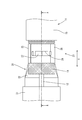
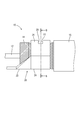
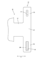
- the partial expansion perspective view of the electric wire with a terminal of one embodiment Partially enlarged plan view of the electric wire with terminal AA sectional view of FIG. Partially enlarged sectional view of FIG. Partially enlarged side view of electric wire with terminal BB sectional view of FIG. Partial enlarged perspective view of terminal Partial enlarged plan view of terminals Terminal cross section
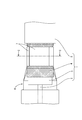
- the partially expanded sectional view which shows the engaging part of the electric wire with a terminal of other embodiments Partial enlarged plan view of a conventional electric wire with terminal CC sectional view of FIG. Partially enlarged plan view of a conventional electric wire with a terminal when the coaxial wire is pulled in the axial direction Sectional view of a conventional electric wire with terminal
- the terminal 20 and the electric wire 10 with a terminal will be described with reference to FIGS.
- the terminal 20 is connected to the end of the electric wire 11.
- the left side of FIG. 2 is assumed to be the front and the right side is assumed to be the rear.
- the electric wire 11 of the present embodiment includes a core wire 12 made of one metal strand or a stranded wire of a plurality of metal strands, a relatively thick inner insulating layer 13, a shield layer 14 made of a braided wire,
- the outer insulating layer 15 made of an insulating material such as a synthetic resin is a so-called coaxial electric wire arranged concentrically from the inside toward the outside (see FIG. 1).
- the terminal of the electric wire 11 is subjected to terminal processing such as peeling, and the terminals of the core wire 12, the inner insulating layer 13, and the shield layer 14 are exposed.
- Terminal 20 The terminal 20 is connected to the core wire 12 and can be connected to a counterpart terminal (not shown), an outer terminal (not shown), an outer terminal connected to the shield layer 14, and interposed between these inner and outer terminals.
- a dielectric (insulator) (not shown) that is in an insulated state. This embodiment relates to a crimping structure of the terminal 20 to the shield layer 14 of the outer terminal.
- the outer terminal (terminal 20) is formed by pressing a metal plate having excellent conductivity, and the front side thereof has a rectangular tube-like fitting cylinder portion 21 (see FIG. 2), and a crimping portion 23 to be crimped to the end of the shield layer 14 is integrally provided on the rear side (see FIGS. 7 to 9).
- the crimping part 23 extends from the bottom wall of the fitting cylinder part 21 to the rear via a connecting part 22 and extends from both side edges of the mounting part 24 to the side. And a pair of barrel pieces 25, 26.
- the left barrel piece in FIG. 7 is referred to as a first barrel piece 25, and the right barrel piece is referred to as a second barrel piece 26.
- the first barrel piece 25 is disposed on the inner side
- the second barrel piece 26 is the first barrel piece 25.
- a so-called overlapped shape is provided so as to overlap the outside (see FIGS. 1 and 6).
- the first barrel piece 25 (an example of one side barrel piece) is formed with an engagement protrusion 27 that protrudes outward in the radial direction of the electric wire 11 in a crimped state.
- the engagement protrusion 27 extends along the extending direction of the first barrel piece 25 (the direction substantially orthogonal to the extending direction X of the electric wire 11), in other words, an elongated shape extending along the circumferential direction of the electric wire 11 in a crimped state.
- the center part is high in the extending direction of the first barrel piece 25, and both ends thereof are loosely inclined and have a generally flat mountain shape.
- the engagement protrusion 27 rises substantially perpendicularly to the plate surface of the first barrel piece 25 in the extending direction X of the electric wire 11 (see FIG. 4).
- the engaging protrusion 27 is formed by press working, and the back side in the protruding direction is recessed in a concave shape.
- the engagement hole 28 extends along the extending direction of the second barrel piece 26 (the direction substantially orthogonal to the extending direction X of the electric wire 11), in other words, along the circumferential direction of the electric wire 11 in the crimped state. It has a long hole shape slightly longer than the length of the engaging protrusion 27 (the dimension along the extending direction of the first barrel piece 25).
- the width dimension of the engagement hole 28 (the dimension along the extending direction X of the electric wire 11) is a dimension that allows the engagement protrusion 27 to be fitted tightly, that is, a dimension that is slightly larger than the width dimension of the engagement protrusion 27. Is set.
- the corner portion is cut obliquely, and serves as a guide portion 28A that guides the engagement protrusion 27 into the engagement hole 28 (see FIGS. 4 and 9). It should be noted that corner portions other than the corner portion where the guide portion 28A is provided are not cut out of the hole edge portion.
- the projecting dimension of the engaging protrusion 27 from the surface of the first barrel piece 25 is set to be smaller than the plate thickness of the second barrel piece 26, whereby the engaging protrusion 27 is formed in the engagement hole 28. In a state where it is engaged with the hole edge portion, it does not protrude from the surface of the second barrel piece 26 (see FIG. 4).
- the projecting dimension of the engaging projection 27 is set to a dimension that is slightly larger than half the plate thickness of the second barrel piece 26.
- the outer sides of the front end edges of the first barrel piece 25 and the second barrel piece 26 are notched obliquely (notches 25A and 26A) and are tapered (see FIG. 6).
- the pair of barrel pieces 25, 26 is in an upwardly open position when the terminal 20 is in a single state, and is crimped so as to be wound around the end of the shield layer 14. ing.
- the engagement protrusion 27 engages with the hole edge of the engagement hole 28, whereby the first barrel piece The relative position between the second barrel piece 26 and the second barrel piece 26 is prevented from shifting in the front-rear direction.
- the engagement protrusion 27 is movable to some extent in the circumferential direction of the electric wire 11 in the engagement hole 28 (see FIG. 6).
- a pair of barrel pieces 25 and 26 of the terminal 20 are in a crimped state in which the pair of barrel pieces 25 and 26 are crimped to the shield layer 14 of the electric wire 11. Since the engagement protrusions 27 of the barrel pieces 25 and 26 and the hole edges of the engagement holes 28 are engaged with each other, even if a force pulling in the axial direction is applied to the electric wire 11, Even if the front end side of each of the barrel pieces 25 and 26 is pulled together with the electric wire 11 (shield layer 14), it is possible to suppress the displacement from the original crimping position in the front-rear direction.
- the pair of barrel pieces 25 and 26 are crimped to the shield layer 14 with a substantially uniform force in the circumferential direction of the electric wire 11. It is possible to maintain the applied state and has excellent adhesion.
- the separation distance between the core wire 12 and the shield layer 14 is kept constant in the circumferential direction, the terminal-attached electric wire 10 having excellent high-frequency characteristics can be obtained.
- the hole edge part of the engagement protrusion 27 and the engagement hole 28 has comprised the shape extended long in the direction substantially orthogonal to the direction X where the electric wire 11 is extended, in other words, in the crimping
- the engaging protrusion 27 is set to have a projecting dimension smaller than the plate thickness of the second barrel piece 26 and is not protruded from the surface of the second barrel piece 26. Interference or catching on parts is suppressed.
- the engagement protrusion 27 is provided in the first barrel piece 25 arranged on the inner side in the crimped state and the engagement hole 28 of the second barrel piece 26 arranged on the outer side is provided, the crimping operation is performed. In this case, the alignment between the engagement protrusion 27 and the engagement hole 28 can be easily performed while visually observing.
- the engagement protrusion 27 is protruded toward the outside of the first barrel piece 25 and is engaged with the hole edge of the engagement hole 28 of the second barrel piece 26 stacked on the outside.
- the engaging protrusion 47 protrudes inward and engages with the edge of the engaging hole 48 of the second barrel piece 46 stacked on the inside. It is good.
- the edge portions of the engagement protrusion 27 and the engagement hole 28 are elongated in a direction substantially orthogonal to the direction X in which the electric wire 11 extends. It is good also as a structure extended diagonally.
- the configuration is not limited to an elongated shape, and a circular shape (cylindrical shape) or a non-elongated rectangular shape (square tube shape) can also be used.
- the protrusion dimension of the engaging protrusion 27 is set to be smaller than the plate thickness of the second barrel piece 26.
- the protrusion dimension is equal to the plate thickness of the second barrel piece 26. You may set to the dimension which protrudes from the surface of 2 barrel pieces 26.
- the engagement hole 28 is a through-hole penetrating the second barrel piece 26, but a bottomed engagement hole recessed in a concave shape is also included in the technology disclosed in this specification.
- the terminal 20 of the above embodiment has a configuration that does not have a barrel piece that is crimped to the outer insulating layer 15, but a configuration that includes a barrel piece that is crimped to the outer insulating layer 15 is also disclosed in the present specification. Technology.
- the shield layer 14 is composed of a braided wire, but is not limited to the braided wire, and a shield layer such as a metal thin film is also included in the technology disclosed in this specification.
- the engagement protrusion 27 is movable in the circumferential direction of the electric wire 11 in the engagement hole 28.
- the length dimension of the engagement protrusion 27 and the engagement hole 28 is substantially the same. It is good also as a structure which makes it equivalent and cannot move also in the circumferential direction of the electric wire 11.
- Electric wire with terminal 11 Electric wire (coaxial wire) 12: Core wire 13: Inner insulating layer 14: Shield layer 15: Outer insulating layer 20: Terminal 23: Crimp part 25: First barrel piece (one barrel piece) 26: Second barrel piece (barrel piece on the other side) 27: engagement protrusion 28: engagement hole X: direction in which the electric wire extends
Landscapes
- Connections Effected By Soldering, Adhesion, Or Permanent Deformation (AREA)
- Coupling Device And Connection With Printed Circuit (AREA)
- Insulated Conductors (AREA)
Abstract
芯線と、内部絶縁層と、シールド層と、外部絶縁層と、が内から外に向けて同心状に配された同軸電線と、前記同軸電線に接続された端子と、を備えた端子付き電線であって、前記端子は、露出された前記シールド層に対してオーバーラップ状に圧着された一対のバレル片を備えており、前記一対のバレル片のうち一方側には、他方側の前記バレル片に向けて突出する係合突部が設けられており、前記係合突部は、前記他方側のバレル片に設けられた係合孔の孔縁部に係合している。
Description
本明細書に開示される技術は、端子および端子付き電線に関する。
従来、芯線の外周側に内部絶縁層、シールド層、外部絶縁層が内から外に向けて同心状に配された同軸電線の端末に、内導体端子および外導体端子を備える端子が接続されてなる電線の接続構造が知られている。
より詳細には、図11に示すように、電線1の端末が皮剥きされることで芯線2と内部絶縁層3とシールド層4とが段階的に露出され、芯線2に内導体端子(図示せず)が接続される一方、シールド層4の端末および外部絶縁層5に、外導体端子6に設けられたシールド層用のバレル片7、および、外部絶縁層用のバレル片(図示せず)がそれぞれ圧着される構造が知られている。
ところで、この種の電線1においては、シールド層4と外部絶縁層5との間が比較的滑り易いという事情がある。このため、電線1の軸方向に引張荷重がかかった場合に、シールド層4から外部絶縁層5が比較的簡単にずれて、外部絶縁層5だけが先に引っ張られる場合がある。このため、シールド層4を圧着するバレル片7にもある程度の固着力が必要とされる。また、端子に外部絶縁層用のバレル片が設けられていない場合には、なおさら、シールド層4を圧着するバレル片7の固着力が必要とされる。
一方、この種の電線1の伝送特性について考慮すると、芯線2とシールド層4との間の離間距離が変化すると高周波特性が低下するため、シールド層4にバレル片7を圧着する際には、内部絶縁層3を変形させることなく、シールド層4の周方向において均等な力で圧着することが好ましい。
しかし、バレル片7を周方向において均等な力で圧着する場合には、バレル片7をその先端側やバレル片に設けた突起をシールド層4に食い込ませつつ圧着する構成と比較して、電線1に対する固着力が低下する傾向にある。
そして、このように固着力が比較的低い圧着部に対し電線1の軸方向の引張荷重がかかると、シールド層4に圧着されている一対のバレル片7のうち特に先端側が比較的容易にその引張方向に引っ張られ、もとの圧着位置からずれる場合がある(図13参照)。このようにバレル片7の先端側がずれると、電線1に対するバレル片7の圧着力が周方向において不均一になり、これに伴って芯線2とシールド層4との間の離間距離が変化するため、高周波特性が低下する虞がある(図14参照)。
本明細書に開示される技術は上記のような事情に基づいて完成されたものであって、同軸電線に対しその軸方向に引っ張る力が加えられた場合でも、シールド層に圧着される一対のバレル片の先端側が軸方向にずれ難く、高周波特性に優れる端子および端子付き電線を提供することを目的とするものである。
本明細書に開示される技術は、芯線と、内部絶縁層と、シールド層と、外部絶縁層と、が内から外に向けて同心状に配された同軸電線に接続される端子であって、露出された前記シールド層に対してオーバーラップ状に圧着される一対のバレル片を備えており、前記一対のバレル片のうち一方側のバレル片には、前記一対のバレル片が前記シールド層に圧着された圧着状態において、前記一対のバレル片のうち他方側のバレル片に向けて突出する係合突部が設けられており、前記他方側のバレル片には、前記圧着状態において前記係合突部をその孔縁部に係合させる係合孔が設けられている。
また本明細書に開示される技術は、芯線と、内部絶縁層と、シールド層と、外部絶縁層と、が内から外に向けて同心状に配された同軸電線と、前記同軸電線に接続された端子と、を備えた端子付き電線であって、前記端子は、露出された前記シールド層に対してオーバーラップ状に圧着された一対のバレル片を備えており、前記一対のバレル片のうち一方側のバレル片には、前記一対のバレル片のうち他方側のバレル片に向けて突出する係合突部が設けられており、前記係合突部は、前記他方側のバレル片に設けられた係合孔の孔縁部に係合している。
上記構成によれば、端子の一対のバレル片が同軸電線のシールド層に圧着された圧着状態においては、一方側のバレル片の係合突部が他方側のバレル片の係合孔の孔縁部に係合した状態とされるから、同軸電線に対してその軸方向に引っ張る力が加えられた場合でも、一対のバレル片の先端側がもとの圧着位置からずれることが抑制される。換言すると、同軸電線に対してその軸方向に引っ張る力が加えられた場合でも、一対のバレル片は同軸電線の周方向においてほぼ均一の力でシールド層に圧着された状態を保つことができる。
もって、芯線とシールド層との間の離間距離が周方向において一定に保たれるから、高周波特性に優れる端子付き電線が得られる。
上記端子は、以下の構成を備えていてもよい。
係合突部および係合孔の孔縁部は、同軸電線の延びる方向に対して交差する方向に長細く延びていてもよい。
係合突部および係合孔の孔縁部は、同軸電線の延びる方向に対して交差する方向に長細く延びていてもよい。
このような構成によれば、同軸電線に対してその軸方向に引っ張る力が加えられた場合に、係合突部および係合孔の孔縁部は同軸電線の延びる方向に対して交差する方向に延びる広い面積で係止状態を保持することができるから、より安定的にシールド層に圧着された状態を保つことができる。
また、係合突部の一方側のバレル片の表面からの突出寸法は、当該係合突部が係合孔の孔縁部に係合した状態において他方側のバレル片の表面から突出しない寸法に設定されていてもよい。
このような構成によれば、係合突部は他方側のバレル片の表面から突出することがないから、係合突部が他の部品に引っかかったり、シールド層に食い込んだりすることが抑制される。
また、係合突部は、圧着状態において同軸電線の径方向の外側に向けて突出するように設けられていてもよい。すなわち、一方側のバレル片の外側に他方側のバレル片が重ねられて圧着される構成としてもよい。
このような構成によれば、圧着作業の際の位置合わせをより簡単に行うことができる。
本明細書に開示される技術によれば、同軸電線に対しその軸方向に引っ張る力が加えられた場合でも、シールド層に圧着された一対のバレル片の先端側が軸方向にずれ難く、高周波特性に優れる端子および端子付き電線が得られる。
一実施形態の端子20および端子付き電線10を図1ないし図9に基づいて説明する。本実施形態では、図1に示すように、電線11の端末に端子20が接続されている。なお以下においては、図2の左側を前方とし、右側を後方として説明する。
(電線11)
本実施形態の電線11は、1本の金属素線若しくは複数本の金属素線の撚り線からなる芯線12と、比較的厚肉の内部絶縁層13と、編組線からなるシールド層14と、合成樹脂等の絶縁材料からなる外部絶縁層15とが、内側から外側に向けて同心状に配された、いわゆる同軸電線である(図1参照)。
本実施形態の電線11は、1本の金属素線若しくは複数本の金属素線の撚り線からなる芯線12と、比較的厚肉の内部絶縁層13と、編組線からなるシールド層14と、合成樹脂等の絶縁材料からなる外部絶縁層15とが、内側から外側に向けて同心状に配された、いわゆる同軸電線である(図1参照)。
この電線11の端末では、皮剥き等の端末処理が施され、芯線12、内部絶縁層13及びシールド層14のそれぞれの端末が露出されている。
(端子20)
端子20は、芯線12に接続されるとともに図示しない相手側端子と接続可能とされる図示しない内側端子と、シールド層14に接続される外側端子と、これら内外の端子間に介在されて両者を絶縁状態とする図示しない誘電体(絶縁体)と、を備えている。本実施形態は、端子20のうち、外側端子のシールド層14に対する圧着構造に関するものである。
端子20は、芯線12に接続されるとともに図示しない相手側端子と接続可能とされる図示しない内側端子と、シールド層14に接続される外側端子と、これら内外の端子間に介在されて両者を絶縁状態とする図示しない誘電体(絶縁体)と、を備えている。本実施形態は、端子20のうち、外側端子のシールド層14に対する圧着構造に関するものである。
外側端子(端子20)は、導電性に優れた金属板をプレス加工して形成され、その前方側は、上記した誘電体が内側に嵌合される四角筒状の嵌合筒部21(図2参照)とされ、後方側には、シールド層14の端末に圧着される圧着部23が一体に設けられている(図7ないし図9参照)。
圧着部23は、嵌合筒部21の底壁から延設された連結部22を介して後方に向けて延びる載置部24と、載置部24の両側縁から側方に向けて延設された一対のバレル片25,26とを備えている。
以下、一対のバレル片25,26のうち図7中左側のバレル片を第1バレル片25、右側のバレル片を第2バレル片26とする。シールド層14に一対のバレル片25,26が圧着された状態(以下、圧着状態とする)においては、第1バレル片25が内側に配され、第2バレル片26が第1バレル片25の外側に重ねて配される、いわゆるオーバーラップ状とされる(図1および図6参照)。
第1バレル片25(一方側のバレル片の一例)には、圧着状態において、電線11の径方向の外側に向けて突出する係合突部27が形成されている。係合突部27は、第1バレル片25の延び方向(電線11の延び方向Xとほぼ直交する方向)に沿って延びる、換言すると、圧着状態において電線11の周方向に沿って延びる細長い形状をなしており、第1バレル片25の延び方向において中央部が高く、その両端部が緩い傾斜状とされた、概ね扁平な山形をなしている。また、係合突部27は、電線11の延び方向Xにおいては第1バレル片25の板面に対しほぼ垂直に立ち上がっている(図4参照)。この係合突部27はプレス加工により形成されており、突出方向の裏側は凹状に窪んでいる。
一方、第2バレル片26(他方側のバレル片の一例)のうち、圧着状態、すなわち、第1バレル片25の外側に重ねられた状態において、第1バレル片25の係合突部27に対応する領域には、係合突部27を内側に嵌め入れてその孔縁部に係合させるための係合孔28が設けられている。
係合孔28は、第2バレル片26の延び方向(電線11の延び方向Xとほぼ直交する方向)に沿って、換言すると、圧着状態において電線11の周方向に沿うように延びており、係合突部27の長さ寸法(第1バレル片25の延び方向に沿った寸法)よりやや長い寸法の長孔状をなしている。また、係合孔28の幅寸法(電線11の延び方向Xに沿った寸法)は、係合突部27をぴったり嵌め入れる寸法、すなわち、係合突部27の幅寸法より僅かに大きい寸法に設定されている。
また、この係合孔28の孔縁部のうち、圧着状態において第1バレル片25側(内側)に配される側、かつ、第2バレル片26の延び方向に沿って配される側の角部は斜めに切り欠かれており、係合突部27を係合孔28内に案内する案内部28Aとされている(図4および図9参照)。なお、孔縁部のうち案内部28Aが設けられた角部以外の角部はいずれも切り欠かれていない。
係合突部27の第1バレル片25の表面からの突出寸法は、第2バレル片26の板厚より小さい寸法に設定されており、これにより、係合突部27は係合孔28の孔縁部に係合した状態において、第2バレル片26の表面から突出しないようになっている(図4参照)。本実施形態において、係合突部27の突出寸法は、第2バレル片26の板厚の半分よりやや大きい程度の寸法に設定されている。
また、第1バレル片25および第2バレル片26の先端縁の外側は斜めに切り欠かれており(切欠部25A,26A)、先細に形成されている(図6参照)。これにより、一対のバレル片25,26がシールド層14に圧着された圧着状態において、第1バレル片25の先端縁の外側の角部が第2バレル片26の内側に干渉することが回避され、一対のバレル片25、26の重ね合わせ状態が良好になる。また、第2バレル片26の先端縁の外側の角部による他部品への引っ掛かりが抑制される。
図7に示すように、一対のバレル片25,26は、端子20の単体状態では上開きの姿勢を採っており、シールド層14の端末に対して巻き付くようにして圧着されるようになっている。
一対のバレル片25,26がシールド層14に圧着された状態では、図4に示すように、係合突部27が係合孔28の孔縁部に係合することにより、第1バレル片25と第2バレル片26との相対的な位置が前後方向にずれないようになっている。一方、係合突部27は係合孔28内において、電線11の周方向にはある程度移動可能とされている(図6参照)。
このような本実施形態の端子20および端子付き電線10によれば、端子20(外側端子)の一対のバレル片25,26が電線11のシールド層14に圧着された圧着状態においては、一対のバレル片25,26の係合突部27と係合孔28の孔縁部とが係合した状態とされるから、電線11に対してその軸方向に引っ張る力が加えられた場合でも、一対のバレル片25,26の先端側が電線11(シールド層14)とともに引っ張られてもとの圧着位置から前後方向にずれることが抑制される。換言すると、電線11(シールド層14)に対してその軸方向に引っ張る力が加えられた場合でも、一対のバレル片25,26は電線11の周方向においてほぼ均一の力でシールド層14に圧着された状態を保つことができ、固着力に優れる。
もって、芯線12とシールド層14との間の離間距離が周方向において一定に保たれるから、高周波特性に優れる端子付き電線10とすることができる。
また、係合突部27および係合孔28の孔縁部は電線11の延びる方向Xに対してほぼ直交する方向に長細く延びる形状をなしているから、換言すると、圧着状態においては電線11の周方向に沿って延びているから、電線11(シールド層14)に対してその軸方向に引っ張る力が加えられた場合に、広い面積で力を受けて係合状態を保持することができる。よって、一対のバレル片25,26をより安定的にシールド層14に圧着された状態に保つことができる。
また、係合突部27は第2バレル片26の板厚より小さい突出寸法に設定されており、第2バレル片26の表面から突出しないようになっているから、係合突部27が他部品に干渉したり引っかかったりすることが抑制される。
また、圧着状態において内側に配される第1バレル片25に係合突部27を設け、外側に配される第2バレル片26の係合孔28を設ける構成としたから、圧着作業の際には、係合突部27と係合孔28との位置合わせを目視しながら簡単に行うことができる。
<他の実施形態>
本明細書に開示される技術は上記記述及び図面によって説明した実施形態に限定されるものではなく、例えば次のような実施形態も技術的範囲に含まれる。
本明細書に開示される技術は上記記述及び図面によって説明した実施形態に限定されるものではなく、例えば次のような実施形態も技術的範囲に含まれる。
(1)上記実施形態では、係合突部27を第1バレル片25の外側に向けて突出させて、外側に重ねられた第2バレル片26の係合孔28の孔縁部に係合させる構成としたが、図10に示すように、係合突部47を内側に向けて突出させ、内側に重ねられた第2バレル片46の係合孔48の孔縁部に係合させる構成としてもよい。
(2)上記実施形態では、係合突部27および係合孔28の孔縁部を電線11の延びる方向Xとほぼ直交する方向に細長く延びる構成としたが、電線11の延びる方向Xに対して斜めに延びる構成としてもよい。また、細長い構成に限らず、円形(円筒形)や、細長くない矩形(角筒形)とすることもできる。
(3)上記実施形態では、係合突部27の突出寸法を第2バレル片26の板厚より小さい寸法に設定したが、第2バレル片26の板厚と同等の突出寸法としたり、第2バレル片26の表面から突出する寸法に設定してもよい。
(4)上記実施形態では、係合孔28を第2バレル片26を貫通する貫通孔としたが、凹状に窪む有底の係合孔も本明細書に開示される技術に含まれる。
(5)上記実施形態の端子20は、外部絶縁層15に圧着されるバレル片を有さない構成としたが、外部絶縁層15に圧着されるバレル片を含む構成も本明細書に開示される技術に含まれる。
(6)上記実施形態では、シールド層14は編組線からなる構成としたが、編組線に限らず、例えは金属薄膜等のシールド層も本明細書に開示される技術に含まれる。
(7)上記実施形態では、係合突部27が係合孔28内において電線11の周方向に移動可能な構成としたが、係合突部27と係合孔28の長さ寸法をほぼ同等とし、電線11の周方向にも移動できない構成としてもよい。
10:端子付き電線
11:電線(同軸電線)
12:芯線
13:内部絶縁層
14:シールド層
15:外部絶縁層
20:端子
23:圧着部
25:第1バレル片(一方側のバレル片)
26:第2バレル片(他方側のバレル片)
27:係合突部
28:係合孔
X:電線の延びる方向
11:電線(同軸電線)
12:芯線
13:内部絶縁層
14:シールド層
15:外部絶縁層
20:端子
23:圧着部
25:第1バレル片(一方側のバレル片)
26:第2バレル片(他方側のバレル片)
27:係合突部
28:係合孔
X:電線の延びる方向
Claims (8)
- 芯線と、内部絶縁層と、シールド層と、外部絶縁層と、が内から外に向けて同心状に配された同軸電線に接続される端子であって、
露出された前記シールド層に対してオーバーラップ状に圧着される一対のバレル片を備えており、
前記一対のバレル片のうち一方側のバレル片には、前記一対のバレル片が前記シールド層に圧着された圧着状態において、前記一対のバレル片のうち他方側のバレル片に向けて突出する係合突部が設けられており、
前記他方側のバレル片には、前記圧着状態において前記係合突部をその孔縁部に係合させる係合孔が設けられている、端子。 - 前記係合突部および前記係合孔の孔縁部は前記同軸電線の延びる方向に対して交差する方向に長細く延びている請求項1に記載の端子。
- 前記係合突部の前記一方側のバレル片の表面からの突出寸法は、当該係合突部が前記係合孔の孔縁部に係合した状態において前記他方側のバレル片の表面から突出しない寸法に設定されている請求項1または請求項2に記載の端子。
- 前記係合突部は、前記圧着状態において前記同軸電線の径方向の外側に向けて突出するように設けられている請求項1ないし請求項3のいずれか一項に記載の端子。
- 芯線と、内部絶縁層と、シールド層と、外部絶縁層と、が内から外に向けて同心状に配された同軸電線と、
前記同軸電線に接続された端子と、を備え、
前記端子は、露出された前記シールド層に対してオーバーラップ状に圧着された一対のバレル片を備えており、
前記一対のバレル片のうち一方側のバレル片には、前記一対のバレル片のうち他方側のバレル片に向けて突出する係合突部が設けられており、
前記係合突部は、前記他方側のバレル片に設けられた係合孔の孔縁部に係合している、端子付き電線。 - 前記係合突部および前記係合孔の孔縁部は前記同軸電線の延びる方向に対して交差する方向に長細く延びている請求項5に記載の端子付き電線。
- 前記係合突部の前記一方側のバレル片の表面からの突出寸法は、前記他方側のバレル片の表面から突出しない寸法に設定されている請求項5または請求項6に記載の端子付き電線。
- 前記一方側のバレル片の外側に前記他方側のバレル片が重ねられて圧着されている請求項5ないし請求項7のいずれか一項に記載の端子付き電線。
Priority Applications (2)
| Application Number | Priority Date | Filing Date | Title |
|---|---|---|---|
| CN201780038239.XA CN109314321B (zh) | 2016-06-21 | 2017-06-02 | 端子以及带端子电线 |
| US16/312,340 US10497492B2 (en) | 2016-06-21 | 2017-06-02 | Terminal and cable with terminal |
Applications Claiming Priority (2)
| Application Number | Priority Date | Filing Date | Title |
|---|---|---|---|
| JP2016122444A JP6724590B2 (ja) | 2016-06-21 | 2016-06-21 | 端子および端子付き電線 |
| JP2016-122444 | 2016-06-21 |
Publications (1)
| Publication Number | Publication Date |
|---|---|
| WO2017221668A1 true WO2017221668A1 (ja) | 2017-12-28 |
Family
ID=60783291
Family Applications (1)
| Application Number | Title | Priority Date | Filing Date |
|---|---|---|---|
| PCT/JP2017/020566 Ceased WO2017221668A1 (ja) | 2016-06-21 | 2017-06-02 | 端子および端子付き電線 |
Country Status (4)
| Country | Link |
|---|---|
| US (1) | US10497492B2 (ja) |
| JP (1) | JP6724590B2 (ja) |
| CN (1) | CN109314321B (ja) |
| WO (1) | WO2017221668A1 (ja) |
Families Citing this family (5)
| Publication number | Priority date | Publication date | Assignee | Title |
|---|---|---|---|---|
| JP7380420B2 (ja) * | 2020-05-27 | 2023-11-15 | 株式会社オートネットワーク技術研究所 | シールド導電路 |
| JP7212111B2 (ja) * | 2020-07-24 | 2023-01-24 | ティーイー コネクティビティ ジャーマニー ゲゼルシャフト ミット ベシュレンクテル ハフツンク | 電気フェルール、電気接続デバイス、および電気コネクタ |
| JP7524849B2 (ja) * | 2021-07-07 | 2024-07-30 | 株式会社オートネットワーク技術研究所 | シールド導電路 |
| DE102021129999A1 (de) * | 2021-11-17 | 2023-05-17 | Te Connectivity Germany Gmbh | Verfahren zum Vercrimpen eines elektrischen Kabels und elektrisches Kabel |
| CN116131034A (zh) * | 2023-01-10 | 2023-05-16 | 立讯汽车技术(上海)有限公司 | 线缆连接器及其制造方法 |
Citations (3)
| Publication number | Priority date | Publication date | Assignee | Title |
|---|---|---|---|---|
| JP2006244815A (ja) * | 2005-03-02 | 2006-09-14 | Sumitomo Wiring Syst Ltd | バレル部の構造 |
| JP2013062168A (ja) * | 2011-09-14 | 2013-04-04 | Yazaki Corp | シールド電線の接続構造 |
| JP2013182727A (ja) * | 2012-02-29 | 2013-09-12 | Yazaki Corp | 端子金具 |
Family Cites Families (16)
| Publication number | Priority date | Publication date | Assignee | Title |
|---|---|---|---|---|
| US4781623A (en) * | 1984-01-16 | 1988-11-01 | Stewart Stamping Corporation | Shielded plug and jack connector |
| US5658163A (en) * | 1995-12-19 | 1997-08-19 | Molex Incorporated | Terminal for connecting electrical wires |
| US5725387A (en) * | 1996-03-01 | 1998-03-10 | Molex Incorporated | System for terminating the shield of a high speed cable |
| US6059607A (en) * | 1998-03-17 | 2000-05-09 | Molex Incorporated | Shielded electrical connector |
| JP3532428B2 (ja) * | 1998-11-27 | 2004-05-31 | 住友電装株式会社 | 端 子 |
| JP2000260504A (ja) * | 1999-03-11 | 2000-09-22 | Jst Mfg Co Ltd | Fpc圧着端子及びこれを用いた芯線の圧着構造 |
| TW555245U (en) * | 2003-01-29 | 2003-09-21 | Hon Hai Prec Ind Co Ltd | Cable connector assembly |
| FR2877150B1 (fr) * | 2004-10-27 | 2007-01-19 | Radiall Sa | Procede de montage d'un connecteur electrique sur un cable coaxial, et un tel connecteur |
| JP4846435B2 (ja) * | 2006-05-10 | 2011-12-28 | 矢崎総業株式会社 | 端子金具及び取付方法 |
| JP4901632B2 (ja) * | 2007-07-30 | 2012-03-21 | 矢崎総業株式会社 | 同軸線用コネクタ及び同軸線接続ユニット |
| JP2009099266A (ja) * | 2007-10-12 | 2009-05-07 | Yazaki Corp | 同軸ケーブル用シールド端子 |
| JP5394713B2 (ja) * | 2008-12-10 | 2014-01-22 | 矢崎総業株式会社 | 圧着端子 |
| JP2012054107A (ja) * | 2010-09-01 | 2012-03-15 | Sumitomo Wiring Syst Ltd | 電線付き端子金具 |
| US8366483B2 (en) * | 2011-02-04 | 2013-02-05 | Tyco Electronics Corporation | Radio frequency connector assembly |
| JP5965736B2 (ja) * | 2012-06-20 | 2016-08-10 | 矢崎総業株式会社 | 電線の端末構造、シールドコネクタ及び電線の端末処理方法 |
| US9153878B2 (en) * | 2013-10-29 | 2015-10-06 | Delphi Technologies, Inc. | Termination assembly for a shielded cable and method of assembling |
-
2016
- 2016-06-21 JP JP2016122444A patent/JP6724590B2/ja not_active Expired - Fee Related
-
2017
- 2017-06-02 US US16/312,340 patent/US10497492B2/en active Active
- 2017-06-02 CN CN201780038239.XA patent/CN109314321B/zh not_active Expired - Fee Related
- 2017-06-02 WO PCT/JP2017/020566 patent/WO2017221668A1/ja not_active Ceased
Patent Citations (3)
| Publication number | Priority date | Publication date | Assignee | Title |
|---|---|---|---|---|
| JP2006244815A (ja) * | 2005-03-02 | 2006-09-14 | Sumitomo Wiring Syst Ltd | バレル部の構造 |
| JP2013062168A (ja) * | 2011-09-14 | 2013-04-04 | Yazaki Corp | シールド電線の接続構造 |
| JP2013182727A (ja) * | 2012-02-29 | 2013-09-12 | Yazaki Corp | 端子金具 |
Also Published As
| Publication number | Publication date |
|---|---|
| US20190221329A1 (en) | 2019-07-18 |
| US10497492B2 (en) | 2019-12-03 |
| CN109314321B (zh) | 2021-01-05 |
| JP6724590B2 (ja) | 2020-07-15 |
| CN109314321A (zh) | 2019-02-05 |
| JP2017228385A (ja) | 2017-12-28 |
Similar Documents
| Publication | Publication Date | Title |
|---|---|---|
| US10910734B2 (en) | Shielded cable with terminal | |
| WO2017221668A1 (ja) | 端子および端子付き電線 | |
| US9130284B2 (en) | Crimp terminal | |
| US11862907B2 (en) | Connector with cable | |
| JP2009099266A (ja) | 同軸ケーブル用シールド端子 | |
| WO2015141614A1 (ja) | 圧着端子と電線の接続構造 | |
| US12034254B2 (en) | Connector, and connector structure | |
| JP7096123B2 (ja) | シールド電線の端子接続構造 | |
| CN104078796B (zh) | 电缆组件 | |
| JP5424055B2 (ja) | 端子金具 | |
| WO2018146797A1 (ja) | 端子付き電線 | |
| WO2017212920A1 (ja) | 端子付き電線 | |
| WO2016167125A1 (ja) | 端子および端子付き電線 | |
| JP2017208211A (ja) | 端子付き電線 | |
| US11764519B2 (en) | Wire including terminal provided with insulating barrel pieces | |
| WO2017073026A1 (ja) | 圧着端子及び端子付き電線 | |
| JP2016167340A (ja) | ジョイント部材及びワイヤーハーネス | |
| JP5966815B2 (ja) | 端子圧着構造及び外導体端子 | |
| JP2015099639A (ja) | 端子金具 | |
| US20260039064A1 (en) | Shielded connector | |
| JP6252867B2 (ja) | 端子金具 | |
| JP5939100B2 (ja) | 端子圧着構造及び端子圧着構造の製造方法 | |
| WO2016186021A1 (ja) | 端子、及び端子付き電線 | |
| JP2018092757A (ja) | 端子 | |
| JP5906543B2 (ja) | 圧着端子付き電線 |
Legal Events
| Date | Code | Title | Description |
|---|---|---|---|
| 121 | Ep: the epo has been informed by wipo that ep was designated in this application |
Ref document number: 17815137 Country of ref document: EP Kind code of ref document: A1 |
|
| NENP | Non-entry into the national phase |
Ref country code: DE |
|
| 122 | Ep: pct application non-entry in european phase |
Ref document number: 17815137 Country of ref document: EP Kind code of ref document: A1 |