WO2017217099A1 - 冷凍サイクル装置 - Google Patents
冷凍サイクル装置 Download PDFInfo
- Publication number
- WO2017217099A1 WO2017217099A1 PCT/JP2017/015188 JP2017015188W WO2017217099A1 WO 2017217099 A1 WO2017217099 A1 WO 2017217099A1 JP 2017015188 W JP2017015188 W JP 2017015188W WO 2017217099 A1 WO2017217099 A1 WO 2017217099A1
- Authority
- WO
- WIPO (PCT)
- Prior art keywords
- refrigerant
- passage
- evaporator
- cooling
- expansion valve
- Prior art date
- Legal status (The legal status is an assumption and is not a legal conclusion. Google has not performed a legal analysis and makes no representation as to the accuracy of the status listed.)
- Ceased
Links
Images








Classifications
-
- B—PERFORMING OPERATIONS; TRANSPORTING
- B60—VEHICLES IN GENERAL
- B60H—ARRANGEMENTS OF HEATING, COOLING, VENTILATING OR OTHER AIR-TREATING DEVICES SPECIALLY ADAPTED FOR PASSENGER OR GOODS SPACES OF VEHICLES
- B60H1/00—Heating, cooling or ventilating devices
- B60H1/00357—Air-conditioning arrangements specially adapted for particular vehicles
- B60H1/00385—Air-conditioning arrangements specially adapted for particular vehicles for vehicles having an electrical drive, e.g. hybrid or fuel cell
- B60H1/004—Air-conditioning arrangements specially adapted for particular vehicles for vehicles having an electrical drive, e.g. hybrid or fuel cell for vehicles having a combustion engine and electric drive means, e.g. hybrid electric vehicles
-
- B—PERFORMING OPERATIONS; TRANSPORTING
- B60—VEHICLES IN GENERAL
- B60H—ARRANGEMENTS OF HEATING, COOLING, VENTILATING OR OTHER AIR-TREATING DEVICES SPECIALLY ADAPTED FOR PASSENGER OR GOODS SPACES OF VEHICLES
- B60H1/00—Heating, cooling or ventilating devices
- B60H1/00642—Control systems or circuits; Control members or indication devices for heating, cooling or ventilating devices
- B60H1/00814—Control systems or circuits characterised by their output, for controlling particular components of the heating, cooling or ventilating installation
- B60H1/00878—Control systems or circuits characterised by their output, for controlling particular components of the heating, cooling or ventilating installation the components being temperature regulating devices
- B60H1/00899—Controlling the flow of liquid in a heat pump system
- B60H1/00921—Controlling the flow of liquid in a heat pump system where the flow direction of the refrigerant does not change and there is an extra subcondenser, e.g. in an air duct
-
- B—PERFORMING OPERATIONS; TRANSPORTING
- B60—VEHICLES IN GENERAL
- B60H—ARRANGEMENTS OF HEATING, COOLING, VENTILATING OR OTHER AIR-TREATING DEVICES SPECIALLY ADAPTED FOR PASSENGER OR GOODS SPACES OF VEHICLES
- B60H1/00—Heating, cooling or ventilating devices
- B60H1/00271—HVAC devices specially adapted for particular vehicle parts or components and being connected to the vehicle HVAC unit
- B60H1/00278—HVAC devices specially adapted for particular vehicle parts or components and being connected to the vehicle HVAC unit for the battery
-
- B—PERFORMING OPERATIONS; TRANSPORTING
- B60—VEHICLES IN GENERAL
- B60H—ARRANGEMENTS OF HEATING, COOLING, VENTILATING OR OTHER AIR-TREATING DEVICES SPECIALLY ADAPTED FOR PASSENGER OR GOODS SPACES OF VEHICLES
- B60H1/00—Heating, cooling or ventilating devices
- B60H1/00321—Heat exchangers for air-conditioning devices
-
- B—PERFORMING OPERATIONS; TRANSPORTING
- B60—VEHICLES IN GENERAL
- B60H—ARRANGEMENTS OF HEATING, COOLING, VENTILATING OR OTHER AIR-TREATING DEVICES SPECIALLY ADAPTED FOR PASSENGER OR GOODS SPACES OF VEHICLES
- B60H1/00—Heating, cooling or ventilating devices
- B60H1/00421—Driving arrangements for parts of a vehicle air-conditioning
-
- B—PERFORMING OPERATIONS; TRANSPORTING
- B60—VEHICLES IN GENERAL
- B60H—ARRANGEMENTS OF HEATING, COOLING, VENTILATING OR OTHER AIR-TREATING DEVICES SPECIALLY ADAPTED FOR PASSENGER OR GOODS SPACES OF VEHICLES
- B60H1/00—Heating, cooling or ventilating devices
- B60H1/00485—Valves for air-conditioning devices, e.g. thermostatic valves
-
- B—PERFORMING OPERATIONS; TRANSPORTING
- B60—VEHICLES IN GENERAL
- B60H—ARRANGEMENTS OF HEATING, COOLING, VENTILATING OR OTHER AIR-TREATING DEVICES SPECIALLY ADAPTED FOR PASSENGER OR GOODS SPACES OF VEHICLES
- B60H1/00—Heating, cooling or ventilating devices
- B60H1/00642—Control systems or circuits; Control members or indication devices for heating, cooling or ventilating devices
- B60H1/00814—Control systems or circuits characterised by their output, for controlling particular components of the heating, cooling or ventilating installation
- B60H1/00878—Control systems or circuits characterised by their output, for controlling particular components of the heating, cooling or ventilating installation the components being temperature regulating devices
- B60H1/00885—Controlling the flow of heating or cooling liquid, e.g. valves or pumps
-
- B—PERFORMING OPERATIONS; TRANSPORTING
- B60—VEHICLES IN GENERAL
- B60H—ARRANGEMENTS OF HEATING, COOLING, VENTILATING OR OTHER AIR-TREATING DEVICES SPECIALLY ADAPTED FOR PASSENGER OR GOODS SPACES OF VEHICLES
- B60H1/00—Heating, cooling or ventilating devices
- B60H1/22—Heating, cooling or ventilating devices the heat source being other than the propulsion plant
-
- B—PERFORMING OPERATIONS; TRANSPORTING
- B60—VEHICLES IN GENERAL
- B60H—ARRANGEMENTS OF HEATING, COOLING, VENTILATING OR OTHER AIR-TREATING DEVICES SPECIALLY ADAPTED FOR PASSENGER OR GOODS SPACES OF VEHICLES
- B60H1/00—Heating, cooling or ventilating devices
- B60H1/32—Cooling devices
-
- B—PERFORMING OPERATIONS; TRANSPORTING
- B60—VEHICLES IN GENERAL
- B60H—ARRANGEMENTS OF HEATING, COOLING, VENTILATING OR OTHER AIR-TREATING DEVICES SPECIALLY ADAPTED FOR PASSENGER OR GOODS SPACES OF VEHICLES
- B60H1/00—Heating, cooling or ventilating devices
- B60H1/32—Cooling devices
- B60H1/3204—Cooling devices using compression
- B60H1/3228—Cooling devices using compression characterised by refrigerant circuit configurations
- B60H1/32281—Cooling devices using compression characterised by refrigerant circuit configurations comprising a single secondary circuit, e.g. at evaporator or condenser side
-
- F—MECHANICAL ENGINEERING; LIGHTING; HEATING; WEAPONS; BLASTING
- F25—REFRIGERATION OR COOLING; COMBINED HEATING AND REFRIGERATION SYSTEMS; HEAT PUMP SYSTEMS; MANUFACTURE OR STORAGE OF ICE; LIQUEFACTION SOLIDIFICATION OF GASES
- F25B—REFRIGERATION MACHINES, PLANTS OR SYSTEMS; COMBINED HEATING AND REFRIGERATION SYSTEMS; HEAT PUMP SYSTEMS
- F25B5/00—Compression machines, plants or systems, with several evaporator circuits, e.g. for varying refrigerating capacity
- F25B5/02—Compression machines, plants or systems, with several evaporator circuits, e.g. for varying refrigerating capacity arranged in parallel
-
- B—PERFORMING OPERATIONS; TRANSPORTING
- B60—VEHICLES IN GENERAL
- B60H—ARRANGEMENTS OF HEATING, COOLING, VENTILATING OR OTHER AIR-TREATING DEVICES SPECIALLY ADAPTED FOR PASSENGER OR GOODS SPACES OF VEHICLES
- B60H1/00—Heating, cooling or ventilating devices
- B60H1/00271—HVAC devices specially adapted for particular vehicle parts or components and being connected to the vehicle HVAC unit
- B60H2001/003—Component temperature regulation using an air flow
-
- B—PERFORMING OPERATIONS; TRANSPORTING
- B60—VEHICLES IN GENERAL
- B60H—ARRANGEMENTS OF HEATING, COOLING, VENTILATING OR OTHER AIR-TREATING DEVICES SPECIALLY ADAPTED FOR PASSENGER OR GOODS SPACES OF VEHICLES
- B60H1/00—Heating, cooling or ventilating devices
- B60H1/00642—Control systems or circuits; Control members or indication devices for heating, cooling or ventilating devices
- B60H1/00814—Control systems or circuits characterised by their output, for controlling particular components of the heating, cooling or ventilating installation
- B60H1/00878—Control systems or circuits characterised by their output, for controlling particular components of the heating, cooling or ventilating installation the components being temperature regulating devices
- B60H2001/00949—Control systems or circuits characterised by their output, for controlling particular components of the heating, cooling or ventilating installation the components being temperature regulating devices comprising additional heating/cooling sources, e.g. second evaporator
-
- B—PERFORMING OPERATIONS; TRANSPORTING
- B60—VEHICLES IN GENERAL
- B60H—ARRANGEMENTS OF HEATING, COOLING, VENTILATING OR OTHER AIR-TREATING DEVICES SPECIALLY ADAPTED FOR PASSENGER OR GOODS SPACES OF VEHICLES
- B60H1/00—Heating, cooling or ventilating devices
- B60H1/32—Cooling devices
- B60H2001/3269—Cooling devices output of a control signal
Definitions
- the present disclosure relates to a refrigeration cycle apparatus.
- an electric vehicle such as an electric vehicle or a hybrid vehicle has a configuration in which electric power stored in a secondary battery such as a battery pack is supplied to an electric motor via an inverter or the like to output driving force for traveling the vehicle.
- Electrical devices such as secondary batteries and inverters are heat-generating devices that increase in temperature due to self-heating, and problems such as malfunctions may occur as the temperature increases. For this reason, in an electric vehicle, the means for cooling the heat-emitting device mounted in the vehicle so that it may become suitable temperature is needed.
- the refrigeration cycle apparatus described in Patent Document 1 cools the first evaporator that cools the blown air that is blown into the vehicle interior and the air that is blown to the heat generating device downstream of the outdoor heat exchanger.
- the second evaporator is arranged in parallel with the refrigerant flow.
- the refrigeration cycle apparatus adjusts the flow rate of the refrigerant flowing through each evaporator to a flow rate according to the load of each evaporator by means of expansion valves provided in both refrigerant passages leading to the respective evaporators.
- the air conditioning and the cooling of the heat generating equipment are both compatible.
- the refrigeration cycle apparatus described in Patent Literature 1 is a refrigerant circuit in which the first evaporator and the second evaporator are connected in parallel to the refrigerant flow on the downstream side of the refrigerant flow of the outdoor heat exchanger. Yes.
- the refrigerant circuit for example, when the cooling capacity required for the first evaporator is reduced in the operation mode in which the outdoor heat exchanger functions as a heat absorber, the refrigerant circuit is provided on the upstream side of the refrigerant flow of the first evaporator.
- the expansion valve may be controlled to a fully open state.
- both expansion valves provided on the upstream side of the refrigerant flow of each evaporator are fully opened, and the flow rate of the refrigerant flowing into the second evaporator can be sufficiently increased. A situation that disappears occurs.
- the conventional refrigeration cycle apparatus cannot sufficiently increase the flow rate of the refrigerant flowing into the second evaporator when the cooling capacity required for the first evaporator is reduced, and the second evaporation
- the cooling capacity in the vessel may be insufficient.
- This disclosure is intended to provide a refrigeration cycle apparatus capable of appropriately exerting the cooling capacity of the second evaporator even when the cooling capacity of the first evaporator is lowered.
- the refrigerant discharged from the compressor flows into the radiator, and then flows in the order of the first expansion, the outdoor heat exchanger, the second expansion valve, the first evaporator, the third expansion valve, It can be set to the refrigerant circuit which flows in order of the 2nd evaporator.
- the refrigeration cycle apparatus is applied to a vehicle air conditioner capable of adjusting the temperature of blown air blown into the vehicle interior and cooling a heat generating device mounted on the vehicle.
- Refrigeration cycle equipment A compressor that compresses and discharges the refrigerant; A radiator that heats the air using the heat of the refrigerant discharged from the compressor; An outdoor heat exchanger for exchanging heat between the refrigerant and the outside air; A first evaporator that cools the blown air by evaporating the refrigerant by heat exchange with the blown air before being heated through the radiator; A second evaporator that cools the cooling air by evaporating the refrigerant by heat exchange with the cooling air that blows air to the heating device; An expansion valve for heating capable of decompressing and expanding the refrigerant flowing into the outdoor heat exchanger; A cooling expansion valve capable of decompressing and expanding the refrigerant flowing into the first evaporator; A cooling expansion valve capable of de
- the refrigerant discharged from the compressor flows in the order of the radiator, the heating expansion valve, and the outdoor heat exchanger, and then flows in the order of the cooling expansion valve and the first evaporator, and the cooling expansion valve and the second evaporator.
- the second refrigerant circuit that sequentially flows can be switched.
- the circuit switching control unit cools the heat generating device in the dehumidifying heating mode in which the blown air cooled by the first evaporator is heated using the heat of the refrigerant flowing through the radiator, the second evaporator When the condition that the flow rate of the refrigerant flowing into the refrigerant is insufficient is switched from the first refrigerant circuit to the second refrigerant circuit.
- the refrigeration cycle apparatus has an outdoor heat exchange in which the second evaporator is connected in series with the refrigerant flow when the condition of insufficient flow rate of the refrigerant flowing into the second evaporator is satisfied.
- the refrigerant circuit is connected in parallel with the first evaporator and the first evaporator.
- a refrigeration cycle apparatus capable of cooling can be realized.
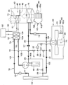
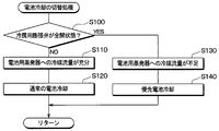
- 1 is an overall configuration diagram of a vehicle air conditioner to which a refrigeration cycle apparatus according to a first embodiment is applied. It is a block diagram of the control apparatus of the refrigerating cycle device of a 1st embodiment. It is a flowchart which shows the flow of the mode determination process which the control apparatus of the refrigerating cycle of 1st Embodiment performs.
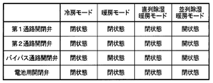
- the refrigerating cycle device of a 1st embodiment it is a chart showing the opening-and-closing state of each on-off valve in each operation mode at the time of not performing battery cooling.
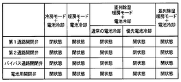
- the refrigerating cycle device of a 1st embodiment it is a chart showing the opening-and-closing state of each on-off valve in each operation mode at the time of performing battery cooling.
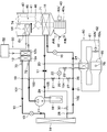
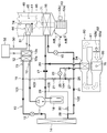
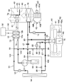
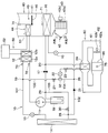
- It is a whole block diagram of the vehicle air conditioner which shows the flow of the refrigerant
- the refrigeration cycle apparatus 10 of the present embodiment has a function of adjusting the temperature in the passenger compartment in the vehicle air conditioner and a function of cooling the secondary battery 65 that stores electric power to be supplied to the electric motor for running the vehicle. Yes.
- the refrigeration cycle apparatus 10 of the present embodiment is configured to be able to cool the cooling air blown to the secondary battery 65 while adjusting the temperature of the blown air blown toward the vehicle interior.
- the secondary battery 65 constitutes a heat generating device mounted on the vehicle.
- the refrigeration cycle apparatus 10 of the present embodiment is configured to be able to switch the refrigerant circuit through which the refrigerant flows according to the operation mode of the air conditioning in the passenger compartment and the presence or absence of battery cooling for cooling the secondary battery 65.
- the refrigeration cycle apparatus 10 can be switched to a cooling mode refrigerant circuit for cooling the passenger compartment, a heating mode refrigerant circuit for heating the passenger compartment, or a dehumidifying heating mode refrigerant circuit for heating while dehumidifying the passenger compartment. It has become.
- the refrigeration cycle apparatus 10 can be switched to a refrigerant circuit that cools the secondary battery 65 when the operation mode of the air conditioning in the passenger compartment is executed.
- the compressor 11 compresses the sucked refrigerant and discharges it.
- the compressor 11 is arrange
- the compressor 11 of the present embodiment is configured by an electric compressor that drives a fixed displacement type compression mechanism with a fixed discharge capacity by an electric motor. The rotational speed of the electric motor of the compressor 11 is controlled in accordance with a control signal from a control device 70 described later.
- the refrigeration cycle apparatus 10 employs an HFC refrigerant (for example, R134a) as a refrigerant.
- the refrigeration cycle apparatus 10 of the present embodiment constitutes a vapor compression subcritical refrigeration cycle in which the refrigerant pressure on the high pressure side in the cycle does not exceed the critical pressure of the refrigerant.
- the refrigeration cycle apparatus 10 is not limited to an HFC-based refrigerant, and an HFO-based refrigerant (for example, R1234yf) or the like may be employed.
- a water refrigerant heat exchanger 12 is connected to the discharge port side of the compressor 11.
- the water-refrigerant heat exchanger 12 is a radiator that radiates heat by exchanging heat from the refrigerant discharged from the compressor 11 with the cooling water of the internal combustion engine 52 that is the fluid to be heated.
- the water-refrigerant heat exchanger 12 radiates the refrigerant discharged from the compressor 11 to the blown air that is indirectly blown into the vehicle interior via the cooling water, so that the blown air blown into the vehicle interior. It is a radiator that heats.
- the water refrigerant heat exchanger 12 of the present embodiment includes a refrigerant side passage 12a through which the refrigerant discharged from the compressor 11 circulates and a cooling water side passage 12b through which the cooling water flowing through the cooling water circuit 50 circulates.
- the refrigerant side passage 12 a is provided between the compressor 11 and the heating expansion valve 13 in the refrigeration cycle apparatus 10. Specifically, the refrigerant side passage 12 a has a refrigerant inlet side connected to the discharge port side of the compressor 11 and a refrigerant outlet side connected to the refrigerant inlet side of the heating expansion valve 13.
- the cooling water side passage 12b is connected to the cooling water outlet side of the internal combustion engine 52 so that the cooling water after passing through the internal combustion engine 52 flows in. Further, the cooling water side passage 12 b has the cooling water outlet side connected to the cooling water inlet side of the heater core 51 so that the cooling water whose temperature has increased due to heat exchange with the refrigerant flows into the heater core 51.
- the heater core 51 is a heat exchanger for heating that heats the air blown into the vehicle interior by exchanging heat between the cooling water and the air blown into the vehicle interior.
- the water refrigerant heat exchanger 12 is connected to a first refrigerant passage 101 that guides the refrigerant flowing out from the refrigerant side passage 12a to an outdoor heat exchanger 14 described later.
- the first refrigerant passage 101 is provided with a heating expansion valve 13.
- the heating expansion valve 13 is an expansion valve that decompresses and expands the refrigerant flowing into the outdoor heat exchanger 14 described later in a heating mode or the like for heating the vehicle interior.
- the heating expansion valve 13 is configured by an electric expansion valve having a valve body that sets the throttle opening and an electric actuator that includes a stepping motor that changes the throttle opening by displacing the valve body. Has been.
- the operation of the heating expansion valve 13 is controlled according to a control signal from a control device 70 described later.
- the heating expansion valve 13 of the present embodiment is configured by a variable throttle mechanism with a full open function that does not substantially exhibit the decompression and expansion action of the refrigerant by fully opening the throttle opening.
- the heating expansion valve 13 constitutes a first expansion valve capable of decompressing and expanding the refrigerant flowing into the outdoor heat exchanger 14.
- the refrigerant inlet side of the outdoor heat exchanger 14 is connected to the refrigerant outlet side of the heating expansion valve 13.
- the outdoor heat exchanger 14 is a heat exchanger that exchanges heat between the refrigerant circulating in the interior and the outside air blown from a blower fan (not shown).
- the outdoor heat exchanger 14 functions as a heat absorber that evaporates the refrigerant and exerts an endothermic effect in a heating mode or the like for heating the vehicle interior, and in the cooling mode or the like for cooling the vehicle interior, It functions as a radiator that condenses and exerts a heat dissipation effect.
- a second refrigerant passage 102 Connected to the refrigerant outlet side of the outdoor heat exchanger 14 is a second refrigerant passage 102 that guides the refrigerant flowing out of the outdoor heat exchanger 14 to the refrigerant suction side of the compressor 11 via an air conditioning evaporator 16 described later. Yes.
- the second refrigerant passage 102 is provided with a cooling expansion valve 15.
- the cooling expansion valve 15 is an expansion valve that decompresses and expands a refrigerant flowing into an air conditioning evaporator 16 (to be described later) in a cooling mode or the like for cooling the passenger compartment.
- the cooling expansion valve 15 is configured by an electric expansion valve having a valve body that sets a throttle opening degree and an electric actuator that includes a stepping motor that changes the throttle opening degree by displacing the valve body. Has been.
- the operation of the cooling expansion valve 15 is controlled according to a control signal from a control device 70 described later.
- the cooling expansion valve 15 of the present embodiment is configured by a variable throttle mechanism with a fully open function that does not substantially exhibit the decompression and expansion action of the refrigerant by fully opening the throttle opening.
- the cooling expansion valve 15 of the present embodiment is a variable throttle mechanism with a fully-closed function that can block the flow of refrigerant into the air-conditioning evaporator 16 by fully closing the throttle opening. It is configured.
- the cooling expansion valve 15 constitutes a second expansion valve capable of decompressing and expanding the refrigerant flowing into the air conditioning evaporator 16 constituting the first evaporator.
- the refrigerant inlet side of the air conditioning evaporator 16 is connected to the refrigerant outlet side of the cooling expansion valve 15.
- the air conditioning evaporator 16 is disposed on the upstream side of the air flow with respect to the heater core 51 in the air conditioning case 41 of the indoor air conditioning unit 40.
- the air conditioning evaporator 16 evaporates the refrigerant decompressed and expanded by the cooling expansion valve 15 by heat exchange with the air before being heated by the heater core 51, so that it is heated before being heated by the heater core 51.
- An evaporator that cools air.
- the air conditioning evaporator 16 constitutes a first evaporator that cools the blown air by heat-exchanging the refrigerant with the blown air that is blown into the passenger compartment and evaporating the refrigerant.
- the ventilation air which ventilates into a vehicle interior comprises the 1st cooling object fluid.
- the refrigerant inlet side of the accumulator 18 is connected to the refrigerant outlet side of the air conditioning evaporator 16 via the pressure regulating valve 17.
- the pressure regulating valve 17 is a constant pressure valve that operates so that the refrigerant pressure of the air conditioning evaporator 16 is maintained at a predetermined pressure.
- the accumulator 18 has a liquid storage function capable of separating the gas-liquid of the refrigerant that has flowed into the accumulator 18, allowing the gas-phase refrigerant to flow out to the refrigerant suction side of the compressor 11, and storing the liquid-phase refrigerant as surplus refrigerant. It is a gas-liquid separator.
- the refrigerant flowing between the water refrigerant heat exchanger 12 and the heating expansion valve 13 bypasses the outdoor heat exchanger 14 and is air-conditioned in the second refrigerant passage 102.
- a third refrigerant passage 103 is provided to guide the refrigerant flow downstream of the evaporator 16 for use.
- the third refrigerant passage 103 has one end connected to a first three-way joint 19 provided between the water refrigerant heat exchanger 12 and the heating expansion valve 13 in the first refrigerant passage 101.
- the other end of the third refrigerant passage 103 is connected to a second three-way joint 20 provided between the air conditioning evaporator 16 and the pressure regulating valve 17 in the second refrigerant passage 102.
- a first passage opening / closing valve 21 for opening and closing the third refrigerant passage 103 is provided in the third refrigerant passage 103.
- the first passage opening / closing valve 21 is composed of an electromagnetic valve whose opening / closing state is controlled in accordance with a control signal output from a control device 70 described later.
- the third refrigerant passage 103 is provided with a cooling expansion valve 22 on the downstream side of the refrigerant flow of the first passage opening / closing valve 21.
- the cooling expansion valve 22 is an expansion valve that decompresses and expands the refrigerant flowing into the battery evaporator 24 described later when the secondary battery 65 is cooled.
- the cooling expansion valve 22 is configured by an electric expansion valve having a valve body that sets a throttle opening degree and an electric actuator that includes a stepping motor that changes the throttle opening degree by displacing the valve body. Has been.
- the operation of the cooling expansion valve 22 is controlled according to a control signal from a control device 70 described later.
- the cooling expansion valve 22 constitutes a third expansion valve capable of decompressing and expanding the refrigerant flowing into the battery evaporator 24 constituting the second evaporator.
- a battery opening / closing valve 23 that opens and closes a refrigerant passage between the cooling expansion valve 22 and the battery evaporator 24 described later in the third refrigerant passage 103.
- the battery open / close valve 23 is configured by an electromagnetic valve whose open / close state is controlled in accordance with a control signal output from a control device 70 described later.
- the refrigerant inlet side of the battery evaporator 24 is connected to the refrigerant outlet side of the battery on-off valve 23.
- the battery evaporator 24 is disposed inside the battery case 61 of the battery pack 60.
- the battery evaporator 24 is a battery cooling evaporator that cools the cooling air by heat-exchanging the refrigerant that has been decompressed and expanded by the cooling expansion valve 22 with the cooling air that is blown to the secondary battery 65.
- the battery evaporator 24 constitutes a second evaporator that evaporates by exchanging heat with the cooling air that blows the refrigerant to the secondary battery 65.
- the cooling air blown to the secondary battery 65 constitutes the second cooling target fluid.
- the refrigeration cycle apparatus 10 includes a portion of the third refrigerant passage 103 between the first passage opening / closing valve 21 and the cooling expansion valve 22, and an outdoor heat exchanger 14 and a cooling expansion valve in the second refrigerant passage 102.
- a fourth refrigerant passage 104 is provided for communicating with the portion 15.
- the fourth refrigerant passage 104 is connected at one end side to a third three-way joint 25 provided between the first passage opening / closing valve 21 and the cooling expansion valve 22 in the third refrigerant passage 103.
- the other end of the fourth refrigerant passage 104 is connected to a fourth three-way joint 26 provided between the outdoor heat exchanger 14 and the cooling expansion valve 15 in the second refrigerant passage 102.
- a second passage opening / closing valve 27 for opening and closing the fourth refrigerant passage 104 is provided in the fourth refrigerant passage 104.
- the second passage opening / closing valve 27 is configured by an electromagnetic valve whose opening / closing state is controlled in accordance with a control signal output from a control device 70 described later.
- the refrigeration cycle apparatus 10 includes a portion of the second refrigerant passage 102 on the upstream side of the refrigerant flow of the fourth three-way joint 26, which is a connection portion with the fourth refrigerant passage 104, and a downstream side of the refrigerant flow of the air conditioning evaporator 16.
- a bypass passage 105 is provided for communicating with the other part.
- bypass passage 105 has one end connected to a fifth three-way joint 28 provided between the outdoor heat exchanger 14 and the fourth three-way joint 26 in the second refrigerant passage 102.
- the bypass passage 105 is connected at its other end to a sixth three-way joint 29 provided between the pressure regulating valve 17 and the accumulator 18 in the second refrigerant passage 102.
- the bypass passage 105 is provided with a bypass passage opening / closing valve 30 that opens and closes the bypass passage 105.
- the bypass passage opening / closing valve 30 is configured by an electromagnetic valve whose opening / closing state is controlled in accordance with a control signal output from a control device 70 described later.
- the second refrigerant passage 102 is a fourth portion which is a connection portion between the fifth three-way joint 28 which is a connection portion with the bypass passage 105 in the second refrigerant passage 102 and the fourth refrigerant passage 104 in the second refrigerant passage 102.
- a backflow prevention valve 31 is provided between the three-way joint 26.
- the backflow prevention valve 31 is a member that prohibits refrigerant from flowing from the fourth refrigerant passage 104 to the bypass passage 105 via the second refrigerant passage 102. That is, the backflow prevention valve 31 is configured to allow the flow of the refrigerant in one direction from the fifth three-way joint 28 to the fourth three-way joint 26 in the second refrigerant passage 102.
- the indoor air conditioning unit 40 is a unit that blows out temperature-adjusted air into the passenger compartment.
- the indoor air conditioning unit 40 is disposed inside the foremost instrument panel in the vehicle interior.
- the indoor air conditioning unit 40 is configured by housing an air conditioning blower 43, an air conditioning evaporator 16, a heater core 51, and the like inside an air conditioning case 41 that forms an outer shell.
- the air conditioning case 41 has an air passage for air blown into the passenger compartment.
- the air conditioning case 41 is formed of a resin (for example, polypropylene) having a certain degree of elasticity and excellent in strength.
- the air volume ratio between the air volume of the vehicle interior air (ie, the inside air) introduced into the air conditioning case 41 and the air volume of the air outside the vehicle compartment (ie, the outside air) is changed.
- An air switching device 42 is arranged.
- An air-conditioning blower 43 that blows air introduced through the inside / outside air switching device 42 toward the vehicle interior is disposed on the downstream side of the air flow of the inside / outside air switching device 42.
- the air-conditioning blower 43 is configured by an electric blower that drives a fan 43a that generates an airflow by an electric motor 43b.
- the rotation speed of the air-conditioning blower 43 is controlled in accordance with a control signal from the control device 70 described later.
- the fan 43a of the air-conditioning blower 43 is composed of a centrifugal multiblade fan (that is, a sirocco fan). Note that the fan 43a is not limited to a centrifugal multiblade fan, and may be an axial fan, a cross flow fan, or the like.
- the air conditioning evaporator 16 and the heater core 51 are arranged in this order on the downstream side of the air flow of the air conditioning blower 43 in the order of the air conditioning evaporator 16 and the heater core 51 with respect to the flow of the blown air. That is, the heater core 51 is disposed on the downstream side of the air flow of the air conditioning evaporator 16.
- the heater core 51 is disposed in the cooling water circuit 50 in which the cooling water of the internal combustion engine 52 that outputs driving force for traveling the vehicle circulates.
- the heater core 51 is a heating heat exchanger that heats the air that has passed through the air conditioning evaporator 16 by causing the cooling water that has flowed out of the water-refrigerant heat exchanger 12 to exchange heat with the air that has passed through the air conditioning evaporator 16. is there.
- the cooling water flow downstream of the water refrigerant heat exchanger 12 in the cooling water circuit 50 is such that the cooling water after passing through both the internal combustion engine 52 and the water refrigerant heat exchanger 12 flows. It is connected to the.
- the cooling water circuit 50 is provided with a water pump for flowing cooling water in the order of the internal combustion engine 52, the water refrigerant heat exchanger 12, and the heater core 51.
- the cooling water circuit 50 is provided with a bypass circuit that bypasses the water-refrigerant heat exchanger 12 and flows cooling water in a cooling mode in which air is not heated by the heater core 51.
- a hot air passage 44 for flowing air to the heater core 51 and a cold air bypass passage 45 for bypassing the heater core 51 to flow air are set on the downstream side of the air flow of the air conditioning evaporator 16. ing.
- an air mix door 46 is arranged on the downstream side of the air flow of the air conditioning evaporator 16 and on the upstream side of the air flow of the heater core 51.
- the air mix door 46 is a member that adjusts the air volume ratio between the air volume of the blown air that flows through the hot air passage 44 and the air flow that flows through the cold air bypass path 45.
- the temperature of the air blown into the passenger compartment changes according to the air volume ratio between the air volume of the blown air flowing through the hot air passage 44 and the air flow flowing through the cold air bypass passage 45.
- the air mix door 46 functions as a temperature adjusting unit that adjusts the temperature of the air blown into the vehicle interior.
- the operation of the air mix door 46 is controlled by a control signal output from the control device 70.
- a merge space (not shown) is formed in which the air that has passed through the hot air passage 44 and the air that has passed through the cold air bypass passage 45 are merged.
- a plurality of opening holes are formed in the most downstream portion of the air-conditioning case 41 to blow out the blown air that has merged in the merge space into the passenger compartment.
- the air conditioning case 41 has an opening hole, a defroster opening hole that blows air toward the inner surface of the window glass on the front of the vehicle, a face opening hole that blows air conditioning air toward the upper body of the passenger in the vehicle interior, A foot opening hole for blowing air-conditioned air toward the feet is formed.
- a defroster door, a face door, and a foot door are arranged on the upstream side of the air flow of each opening hole as a blowing mode door for adjusting the opening area of each opening hole.
- These blow mode doors are driven by an actuator whose operation is controlled by a control signal output from the control device 70 via a link mechanism or the like (not shown).
- the battery pack 60 is disposed, for example, on the vehicle bottom side between the trunk room at the rear of the vehicle and the rear seat.
- the battery pack 60 includes a metal battery case 61 that has been electrically insulated.
- the battery case 61 has an air passage through which cooling air for cooling the secondary battery 65 circulates.
- the battery case 61 houses a battery blower 62, a secondary battery 65, a battery evaporator 24, and the like.
- the battery blower 62 blows the cooling air cooled by the battery evaporator 24 to the secondary battery 65.
- the battery blower 62 is configured by an electric blower that drives a fan 62a that generates an airflow by an electric motor 62b.
- the rotation speed of the battery blower 62 is controlled according to a control signal from the control device 70 described later.
- the secondary battery 65 is configured by connecting a series connection of a plurality of cells in parallel.
- the secondary battery 65 is composed of, for example, a lithium ion battery.
- the secondary battery 65 tends to easily deteriorate when the battery temperature becomes high. For this reason, the secondary battery 65 needs to be adjusted so that the battery temperature is, for example, 40 ° C. or less.
- the control device 70 includes a microcomputer including a storage unit such as a CPU, a ROM, and a RAM and its peripheral circuits.
- the control device 70 performs various calculations and processes based on the control program stored in the storage unit. And the control apparatus 70 controls the action
- the storage unit of the control device 70 is configured by a non-transitional tangible storage medium.
- an inside air sensor that detects the inside air temperature Tr, an outside air sensor that detects the outside air temperature Tam, and the amount of solar radiation As that enters the vehicle interior are detected.
- a solar radiation sensor or the like is connected.
- a first temperature sensor 71 for detecting the air temperature Te after passing through the air conditioning evaporator 16 is connected to the input side of the control device 70. Further, on the input side of the control device 70, a second temperature sensor 72 for detecting the temperature Td of the high-pressure refrigerant flowing into the water refrigerant heat exchanger 12, and a refrigerant pressure Pd after passing through the water refrigerant heat exchanger 12 are detected. A refrigerant pressure sensor 73 and the like are connected. Further, an air outlet temperature sensor 74 for detecting the air temperature TAV of air blown into the vehicle interior, a battery temperature sensor 75 for detecting the battery temperature Tb of the secondary battery 65, and the like are connected to the input side of the control device 70. .
- the 1st temperature sensor 71 of this embodiment although the sensor which detects the temperature of the heat exchange fin of the evaporator 16 for air conditioning and the sensor which detects the temperature of the refrigerant
- the structure which detects the blowing air temperature TAV by the blowing temperature sensor 74 is illustrated, it is not restricted to this, for example, the detected value of the 1st temperature sensor 71, the detected value of the 2nd temperature sensor 72, etc.
- the blown air temperature TAV may be calculated based on the above.
- an operation panel 80 in which various air conditioning operation switches are arranged is connected to the input side of the control device 70. Operation signals from various air conditioning operation switches on the operation panel 80 are input to the control device 70.
- an operation switch for a vehicle air conditioner As various air conditioning operation switches, an operation switch for a vehicle air conditioner, a temperature setting switch for setting a target temperature in the passenger compartment, and whether or not air is cooled by the air conditioning evaporator 16 are set.
- a C switch or the like is provided.
- control device 70 of the present embodiment is a device in which a plurality of control units configured by hardware and software for controlling various control devices connected to the output side are integrated.
- the control device 70 switches the refrigerant circuit in the cycle by changing the operation mode of the air conditioning in the passenger compartment and the mode determination unit 70a that determines whether or not the battery can be cooled, and the open / close states of the open / close valves 21, 23, 27, and 30.
- the switching control unit 70b and the like are integrated.
- each on-off valve 21, 23, 27, 30 constitutes a circuit switching device that switches a refrigerant circuit through which the refrigerant flows.
- the switching control unit 70 b constitutes an opening / closing control unit that controls the first passage opening / closing valve 21 and the second passage opening / closing valve 27.
- the refrigeration cycle apparatus 10 of the present embodiment can perform air conditioning in the passenger compartment and cooling of the secondary battery 65.
- a cooling mode As the operation mode of the air conditioning in the passenger compartment, a cooling mode, a heating mode, a series dehumidifying heating mode, and a parallel dehumidifying heating mode can be set.
- the operation mode is switched by the control device 70 executing a control program stored in the storage unit.
- FIG. 3 is a flowchart showing a flow of mode switching processing executed by the control device 70. Note that each control step shown in FIG. 3 constitutes a function realization unit that realizes various functions executed by the control device 70.
- control device 70 sets the target blowing temperature TAO of the air blown into the vehicle interior based on the detection values of various sensors in step S10. calculate.
- the control device 70 calculates the target blowing temperature TAO based on the following formula F1.
- TAO Kset ⁇ Tset ⁇ Kr ⁇ Tr ⁇ Kam ⁇ Tam ⁇ Ks ⁇ As + C (F1)
- Tset in Formula F1 is a set temperature in the vehicle interior set by the temperature setting switch.
- Kset, Kr, Kam, and Ks in Formula F1 are preset control gains.
- C in Formula F1 is a correction constant.
- step S20 the control device 70 determines whether or not the A / C switch is turned on. As a result, when it is determined that the A / C switch is not turned on, the control device 70 determines the operation mode to be the heating mode in step S30.
- This heating mode is an operation mode in which the air blown into the vehicle interior is heated by the heater core 51 and blown into the vehicle interior without being cooled by the air conditioning evaporator 16.
- the control device 70 determines whether the target blowing temperature TAO is lower than a predetermined cooling determination threshold Th1 in step S40. Determine. As a result, when it is determined that the target blowout temperature TAO is lower than the cooling determination threshold Th1, the control device 70 determines the operation mode as the cooling mode in step S50.
- the cooling mode is an operation mode in which the air blown into the vehicle interior is cooled by the air conditioning evaporator 16 and then blown out into the vehicle interior without passing through the heater core 51.
- the cooling determination threshold Th1 is set to a temperature in the vicinity of the set temperature Tset in the passenger compartment set by the temperature setting switch, for example.
- step S40 when it is determined in step S40 that the target blowing temperature TAO is equal to or higher than the cooling determination threshold Th1, the control device 70 determines that the temperature difference between the blowing air temperature TAV and the target blowing temperature TAO is a predetermined value in step S60. It is determined whether or not it is smaller than the threshold value ⁇ Th.
- the control device 70 determines the operation mode to be the parallel dehumidification heating mode in step S70.
- the parallel dehumidifying and heating mode is an operation mode in which the temperature of the air blown into the passenger compartment can be maximized in the dehumidifying and heating mode.
- control device 70 sets the operation mode to the series dehumidification heating mode in step S80. To decide.
- the series dehumidifying heating mode is an operation mode in which the temperature of the air blown into the passenger compartment can be lowered as compared with the parallel dehumidifying heating mode.
- the parallel dehumidifying and heating mode is an operation mode in which the temperature of the air blown into the vehicle compartment can be increased as compared with the serial dehumidifying and heating mode.
- the refrigeration cycle apparatus 10 of the present embodiment is configured to be switchable between the cooling mode, the heating mode, the series dehumidifying heating mode, and the parallel dehumidifying heating mode according to the air conditioning environment.
- control device 70 controls each on-off valve 21, 23, 27, 30 to change the refrigerant circuit through which the refrigerant flows into the cooling mode, the heating mode, the series dehumidification heating mode, And it switches to the refrigerant circuit corresponding to parallel dehumidification heating mode.
- the battery temperature Tb of the secondary battery 65 is a predetermined high-temperature side reference temperature Tbh (for example, 30 ° C.). If it becomes above, the battery cooling which cools the secondary battery 65 will be performed.
- the control device 70 controls each of the open / close valves 21, 23, 27, and 30 to control the cooling mode, the heating mode, and the dehumidification for battery cooling as shown in FIG. It switches to the refrigerant circuit corresponding to heating mode and parallel dehumidification heating mode.
- the operation of the refrigeration cycle apparatus 10 in each operation mode will be described.
- (A) Cooling Mode First, the operation of the refrigeration cycle apparatus 10 when battery cooling is not performed in the cooling mode will be described.
- the control device 70 controls the on-off valves 21, 23, 27, and 30 to be closed. Further, the control device 70 controls the heating expansion valve 13 so that the throttle opening is fully opened, and controls the cooling expansion valve 15 so as to be in the throttle state.
- the refrigerant circuit in the cycle becomes a circuit through which the refrigerant flows as indicated by the thick black lines with arrows in FIG.
- the control device 70 determines operating states (for example, control signals) of various control devices connected to the output side.
- the control device 70 determines the control signal output to the compressor 11 as follows. First, the control device 70 determines the target evaporator temperature TEO of the air-conditioning evaporator 16 with reference to the control map stored in advance in the storage unit, based on the target outlet temperature TAO. The control device 70 then compresses the compressor so that the air temperature Te of the air conditioning evaporator 16 approaches the target evaporator temperature TEO based on the deviation between the target evaporator temperature TEO and the detected value of the first temperature sensor 71. 11 is determined. The target evaporator temperature TEO is determined so as to be equal to or higher than a temperature (for example, 1 ° C.) that can prevent frosting of the air conditioning evaporator 16.
- a temperature for example, 1 ° C.
- control device 70 determines a control signal output to the air-conditioning blower 43 with reference to a control map stored in advance in the storage unit based on the target blowing temperature TAO. For example, when the target blowing temperature TAO becomes low and high, the control device 70 causes the air volume of the air conditioning blower 43 to become the maximum air volume, and the air volume of the air conditioning blower 43 decreases as the target blowing temperature TAO approaches the intermediate temperature. The control signal is determined.
- control device 70 sets the control signal output to the cooling expansion valve 15 so that the degree of supercooling of the refrigerant flowing into the cooling expansion valve 15 is such that the cycle coefficient of performance (that is, COP) is substantially the maximum value. Decide to approach the degree of supercooling.
- control device 70 controls the air mix door 46 to a position where the hot air passage 44 is closed. Note that the control device 70 may control the air mix door 46 so that the blown air temperature TAV approaches the target blown temperature TAO by feedback control or the like.
- Control device 70 outputs the control signal determined as described above to various control devices. Thereby, the refrigerant discharged from the compressor 11 flows into the refrigerant side passage 12a of the water refrigerant heat exchanger 12.
- the cooling water circuit 50 of the present embodiment is configured such that the cooling water flows around the water refrigerant heat exchanger 12 during the cooling mode. For this reason, the refrigerant that has flowed into the water-refrigerant heat exchanger 12 flows out of the water-refrigerant heat exchanger 12 without radiating heat to the cooling water.
- the warm air passage 44 is closed by the air mix door 46, the air in the air conditioning case 41 is blown into the vehicle interior without being heated by the heater core 51.
- the refrigerant that has flowed out of the water refrigerant heat exchanger 12 flows into the outdoor heat exchanger 14 with almost no decompression and expansion at the heating expansion valve 13 because the heating expansion valve 13 is fully open.
- the first passage opening / closing valve 21 is in the closed state, so that the refrigerant does not flow into the third refrigerant passage 103.
- the refrigerant that has flowed into the outdoor heat exchanger 14 exchanges heat with the outside air to dissipate heat.
- the refrigerant flowing out of the outdoor heat exchanger 14 flows into the cooling expansion valve 15 through the backflow prevention valve 31 and is decompressed and expanded.
- the bypass passage opening / closing valve 30 and the second passage opening / closing valve 27 are closed, the refrigerant does not flow into the fourth refrigerant passage 104 and the bypass passage 105.
- the refrigerant that has flowed out of the cooling expansion valve 15 flows into the air conditioning evaporator 16, absorbs heat from the blown air blown into the passenger compartment, and evaporates. Thereby, the blowing air blown into the passenger compartment is cooled and dehumidified.
- the refrigerant that has flowed out of the air conditioning evaporator 16 flows into the accumulator 18 via the pressure regulating valve 17 and is separated into gas and liquid.
- the gas-phase refrigerant separated by the accumulator 18 is sucked into the compressor 11 and compressed again.
- the liquid-phase refrigerant separated by the accumulator 18 is stored inside the accumulator 18 as an unnecessary surplus refrigerant in order to exhibit the refrigeration capacity required by the refrigeration cycle apparatus 10. The same applies to other operation modes described later.
- the control device 70 controls the first passage opening / closing valve 21 and the bypass passage opening / closing valve 30 to be closed, and the second passage opening / closing valve 27 and the battery opening / closing valve 23. Control to open state. Further, the control device 70 controls the heating expansion valve 13 so that the throttle opening is fully opened, and controls the cooling expansion valve 15 and the cooling expansion valve 22 so as to be in the throttle state.
- the refrigerant circuit in the cycle becomes a circuit through which the refrigerant flows as shown by the thick black lines with arrows in FIG.
- the control device 70 determines operating states (for example, control signals) of various control devices connected to the output side.
- the control device 70 determines, for example, the control signal output to the cooling expansion valve 22 so that the flow rate of the refrigerant in the battery evaporator 24 increases when the battery temperature Tb of the secondary battery 65 becomes high. That is, the control device 70 controls the cooling expansion valve 22 so that the throttle opening increases as the battery temperature Tb of the secondary battery 65 increases.
- control device 70 determines a control signal output to the battery blower 62 so that the air volume blown to the secondary battery 65 becomes a predetermined air volume determined in advance. Note that control signals to be output to other control devices are determined in the same manner as in the cooling mode described above.
- Control device 70 outputs the control signal determined as described above to various control devices. Thereby, the refrigerant discharged from the compressor 11 flows into the refrigerant side passage 12a of the water refrigerant heat exchanger 12.
- the cooling water circuit 50 of the present embodiment is configured such that the cooling water flows around the water refrigerant heat exchanger 12 during the cooling mode. For this reason, the refrigerant that has flowed into the water-refrigerant heat exchanger 12 flows out of the water-refrigerant heat exchanger 12 without radiating heat to the cooling water.
- the warm air passage 44 is closed by the air mix door 46, the air in the air conditioning case 41 is blown into the vehicle interior without being heated by the heater core 51.
- the refrigerant that has flowed out of the water refrigerant heat exchanger 12 flows into the outdoor heat exchanger 14 with almost no decompression and expansion at the heating expansion valve 13 because the heating expansion valve 13 is fully open.
- the first passage opening / closing valve 21 is in the closed state, so that the refrigerant does not flow into the third refrigerant passage 103.
- the refrigerant that has flowed into the outdoor heat exchanger 14 exchanges heat with the outside air to dissipate heat.
- the refrigerant flowing out of the outdoor heat exchanger 14 flows into both the cooling expansion valve 15 and the cooling expansion valve 22 because the second passage opening / closing valve 27 and the battery opening / closing valve 23 are in the open state. .
- the bypass passage opening / closing valve 30 is in a closed state, so that no refrigerant flows into the bypass passage 105.
- the refrigerant that has flowed from the outdoor heat exchanger 14 to the cooling expansion valve 15 side absorbs heat from the blown air that is blown into the vehicle interior by the air conditioning evaporator 16 after flowing into the cooling expansion valve 15 and decompressed and expanded. Evaporate. Thereby, the blowing air blown into the passenger compartment is cooled and dehumidified.
- the refrigerant that has flowed out of the air conditioning evaporator 16 flows into the accumulator 18 through the pressure regulating valve 17.
- the gas-phase refrigerant separated by the accumulator 18 is sucked into the compressor 11 and compressed again.
- the refrigerant that has flowed from the outdoor heat exchanger 14 to the cooling expansion valve 22 side flows into the cooling expansion valve 22 and is decompressed and expanded, and then cooled by the battery evaporator 24 to the secondary battery 65. It absorbs heat from the air and evaporates. Thereby, the cooling air sent to the secondary battery 65 is cooled.
- the refrigerant that has flowed out of the battery evaporator 24 flows into the accumulator 18 through the pressure adjustment valve 17.
- the gas-phase refrigerant separated by the accumulator 18 is sucked into the compressor 11 and compressed again.
- (C) Heating mode Next, the operation of the refrigeration cycle apparatus 10 when battery cooling is not performed in the heating mode will be described.
- the control device 70 controls the first passage opening / closing valve 21, the second passage opening / closing valve 27, and the battery opening / closing valve 23 to be closed, and the bypass passage opening / closing valve 30. Is controlled to open. Further, the control device 70 controls the heating expansion valve 13 so as to be in the throttle state, and controls the cooling expansion valve 15 so as to be in the fully closed state.
- the refrigerant circuit in the cycle becomes a circuit through which the refrigerant flows as shown by the thick black lines with arrows in FIG.
- the control device 70 determines operating states (for example, control signals) of various control devices connected to the output side.
- the control device 70 controls the compressor 11 by, for example, feedback control or the like so that the blown air temperature TAV approaches the target blown temperature TAO.
- the control device 70 sets the control signal output to the heating expansion valve 13 so that the degree of supercooling of the refrigerant flowing into the heating expansion valve 13 is such that the coefficient of performance of the cycle (that is, COP) is substantially maximum. Decide to approach the degree of supercooling.
- the control device 70 controls the air mix door 46 to a position where the cold air bypass passage 45 is closed. Note that the control device 70 may control the air mix door 46 so that the blown air temperature TAV approaches the target blown temperature TAO by feedback control or the like. Note that control signals to be output to other control devices are determined in the same manner as in the cooling mode described above.
- Control device 70 outputs the control signal determined as described above to various control devices. Thereby, the refrigerant discharged from the compressor 11 flows into the refrigerant side passage 12a of the water refrigerant heat exchanger 12. The refrigerant flowing into the water-refrigerant heat exchanger 12 exchanges heat with the cooling water before flowing into the heater core 51 and radiates heat.
- the cooling water heated by the water-refrigerant heat exchanger 12 flows into the heater core 51. Since the cold air bypass passage 45 is closed by the air mix door 46 in the heating mode, the air in the air conditioning case 41 is heated by the heater core 51 and then blown into the vehicle interior. For this reason, in the heating mode of this embodiment, the blowing air blown into the vehicle interior is heated using the heat of the refrigerant flowing through the water-refrigerant heat exchanger 12.
- the refrigerant flowing out of the water refrigerant heat exchanger 12 flows into the heating expansion valve 13 and is decompressed and expanded. Then, the refrigerant decompressed and expanded by the heating expansion valve 13 flows into the outdoor heat exchanger 14. In the heating mode, the first passage opening / closing valve 21 is in a closed state, so that no refrigerant flows into the third refrigerant passage 103.
- the refrigerant flowing into the outdoor heat exchanger 14 absorbs heat from the outside air and evaporates.
- the refrigerant flowing out of the outdoor heat exchanger 14 flows into the accumulator 18 through the bypass passage 105 because the cooling expansion valve 15 is fully closed and the bypass passage opening / closing valve 30 is open.
- the gas-phase refrigerant separated by the accumulator 18 is sucked into the compressor 11 and compressed again.
- a refrigerant circuit that evaporates the refrigerant radiated by the water-refrigerant heat exchanger 12 using the outdoor heat exchanger 14 is provided. For this reason, when battery cooling is not performed in the heating mode, the vehicle interior can be heated by blowing air heated using the heat of the refrigerant flowing through the water-refrigerant heat exchanger 12 into the vehicle interior. it can.
- the control device 70 controls the second passage opening / closing valve 27 to be closed, and the first passage opening / closing valve 21, the bypass passage opening / closing valve 30, and the battery opening / closing valve 23. Is controlled to open. Further, the control device 70 controls the heating expansion valve 13 and the cooling expansion valve 22 so as to be in the throttle state, and controls the cooling expansion valve 15 so as to be in the fully closed state.
- the refrigerant circuit in the cycle becomes a circuit through which the refrigerant flows as shown by the thick black lines with arrows in FIG.
- the control device 70 determines operating states (for example, control signals) of various control devices connected to the output side.
- control device 70 determines that the control signal output to the cooling expansion valve 22 increases the flow rate of the refrigerant flowing into the battery evaporator 24 when the battery temperature Tb of the secondary battery 65 becomes high. To do. That is, the control device 70 controls the cooling expansion valve 22 so that the throttle opening increases as the battery temperature Tb of the secondary battery 65 increases.
- control device 70 determines a control signal output to the battery blower 62 so that the air volume blown to the secondary battery 65 becomes a predetermined air volume determined in advance. In addition, about the control signal output to other control apparatuses, it determines similarly to the above-mentioned heating mode.
- Control device 70 outputs the control signal determined as described above to various control devices.
- the refrigerant discharged from the compressor 11 flows into the refrigerant side passage 12a of the water refrigerant heat exchanger 12.
- the refrigerant flowing into the water-refrigerant heat exchanger 12 exchanges heat with the cooling water before flowing into the heater core 51 and radiates heat.
- the cooling water heated by the water / refrigerant heat exchanger 12 flows into the heater core 51.
- the blown air flowing through the air conditioning case 41 is heated by heat exchange with the cooling water flowing through the heater core 51 and then blown out into the vehicle interior.
- the refrigerant that has flowed out of the water-refrigerant heat exchanger 12 has the second passage opening / closing valve 27 closed and the first passage opening / closing valve 21 and the battery opening / closing valve 23 open. It flows into both of the cooling expansion valves 22.
- the refrigerant flowing from the water refrigerant heat exchanger 12 to the heating expansion valve 13 side flows into the heating expansion valve 13 and is decompressed and expanded, and then absorbs heat from the outside air in the outdoor heat exchanger 14 and evaporates.
- the refrigerant flowing out of the outdoor heat exchanger 14 flows into the accumulator 18 through the bypass passage 105 because the cooling expansion valve 15 is fully closed and the bypass passage opening / closing valve 30 is open.
- the gas-phase refrigerant separated by the accumulator 18 is sucked into the compressor 11 and compressed again.
- the refrigerant that has flowed from the water refrigerant heat exchanger 12 to the cooling expansion valve 22 side flows into the cooling expansion valve 22 and is decompressed and expanded, and then is blown to the secondary battery 65 by the battery evaporator 24. It absorbs heat from the cooling air and evaporates. Thereby, the cooling air sent to the secondary battery 65 is cooled.
- the refrigerant that has flowed out of the battery evaporator 24 flows into the accumulator 18 through the pressure adjustment valve 17.
- the gas-phase refrigerant separated by the accumulator 18 is sucked into the compressor 11 and compressed again.
- the refrigerant circuit in the cycle becomes a circuit through which the refrigerant flows as shown by the thick black lines with arrows in FIG. That is, in the series dehumidifying heating mode, as shown in FIG. 10, the outdoor heat exchanger 14 and the air conditioning evaporator 16 are connected in series to the refrigerant flow.
- the control device 70 determines operating states (for example, control signals) of various control devices connected to the output side.
- the control device 70 controls the air mix door 46 to a position where the cold air bypass passage 45 is closed, for example. Note that the control device 70 may control the air mix door 46 so that the blown air temperature TAV approaches the target blown temperature TAO by feedback control or the like.
- control device 70 determines control signals for the heating expansion valve 13 and the cooling expansion valve 15 according to the target blowing temperature TAO.
- the control device 70 of the present embodiment controls the heating expansion valve 13 so that the throttle opening becomes smaller as the target blowing temperature TAO increases, and the cooling expansion valve so that the throttle opening becomes larger. 15 is controlled.
- control device 70 of the present embodiment is configured such that when the target blowing temperature TAO is equal to or higher than a predetermined determination reference temperature, the heating expansion valve 13 and the cooling expansion valve are configured so that the outdoor heat exchanger 14 functions as a radiator. 15 is controlled. Further, the control device 70 of the present embodiment sets the heating expansion valve 13 and the cooling expansion valve 15 so that the outdoor heat exchanger 14 functions as a heat absorber when the target blowing temperature TAO becomes lower than the determination reference temperature. Control. In addition, about the control signal output to other control apparatuses, it determines similarly to the above-mentioned heating mode.
- Control device 70 outputs the control signal determined as described above to various control devices.
- the case where the outdoor heat exchanger 14 functions as a radiator is referred to as a first mode
- the case where the outdoor heat exchanger 14 functions as a heat absorber is referred to as a second mode.
- the state of the refrigerant flowing through the refrigerant circuit will be described.
- (E-1) First Mode In the first mode of the series dehumidifying heating mode, the refrigerant discharged from the compressor 11 flows into the refrigerant side passage 12a of the water refrigerant heat exchanger 12.
- the refrigerant flowing into the water-refrigerant heat exchanger 12 exchanges heat with the cooling water before flowing into the heater core 51 and radiates heat.
- the cooling water heated by the water / refrigerant heat exchanger 12 flows into the heater core 51.
- the blown air flowing through the air conditioning case 41 is heated by heat exchange with the cooling water flowing through the heater core 51 and then blown out into the vehicle interior.
- the refrigerant that has flowed out of the water-refrigerant heat exchanger 12 is decompressed and expanded by the heating expansion valve 13 or flows into the outdoor heat exchanger 14 with almost no decompression and expansion by the heating expansion valve 13. Note that, during the main operation mode, the first passage opening / closing valve 21 is in the closed state, so that no refrigerant flows into the third refrigerant passage 103.
- the refrigerant that has flowed into the outdoor heat exchanger 14 exchanges heat with the outside air to dissipate heat.
- the refrigerant flowing out of the outdoor heat exchanger 14 flows into the cooling expansion valve 15 through the backflow prevention valve 31 and is decompressed and expanded.
- the bypass passage opening / closing valve 30 and the second passage opening / closing valve 27 are closed, so that the refrigerant does not flow into the fourth refrigerant passage 104 and the bypass passage 105.
- the refrigerant that has flowed out of the cooling expansion valve 15 flows into the air conditioning evaporator 16, absorbs heat from the air before passing through the heater core 51, and evaporates. Thereby, the air after being dehumidified by the air conditioning evaporator 16 flows into the heater core 51.
- the refrigerant that has flowed out of the air conditioning evaporator 16 flows into the accumulator 18 via the pressure regulating valve 17 and is separated into gas and liquid.
- the gas-phase refrigerant separated by the accumulator 18 is sucked into the compressor 11 and compressed again.
- the refrigerant circuit that evaporates the refrigerant radiated by both the water-refrigerant heat exchanger 12 and the outdoor heat exchanger 14 by the air-conditioning evaporator 16 is provided.
- the air-conditioning evaporator 16 after being dehumidified by the air-conditioning evaporator 16, the air heated by using the heat of the refrigerant flowing through the water-refrigerant heat exchanger 12 is blown out into the passenger compartment. Indoor dehumidification heating can be performed.
- the outdoor heat exchanger 14 functions as a radiator.
- coolant heat exchanger 12 can be reduced, ensuring the heat absorption amount of the refrigerant
- the dehumidified low-temperature hot air can be blown into the vehicle interior.
- (E-2) Second Mode In the second mode of the series dehumidifying heating mode, the refrigerant discharged from the compressor 11 flows into the refrigerant side passage 12a of the water refrigerant heat exchanger 12.
- the refrigerant flowing into the water-refrigerant heat exchanger 12 exchanges heat with the cooling water before flowing into the heater core 51 and radiates heat.
- the cooling water heated by the water / refrigerant heat exchanger 12 flows into the heater core 51.
- the blown air flowing through the air conditioning case 41 is heated by heat exchange with the cooling water flowing through the heater core 51 and then blown out into the vehicle interior.
- the refrigerant flowing out of the water refrigerant heat exchanger 12 is decompressed and expanded by the heating expansion valve 13. Then, the refrigerant decompressed and expanded by the heating expansion valve 13 flows into the outdoor heat exchanger 14. Note that, during the main operation mode, the first passage opening / closing valve 21 is in the closed state, so that no refrigerant flows into the third refrigerant passage 103.
- the refrigerant flowing into the outdoor heat exchanger 14 exchanges heat with the outside air and absorbs heat.
- the refrigerant that has flowed out of the outdoor heat exchanger 14 is decompressed and expanded by the cooling expansion valve 15 or flows into the air conditioning evaporator 16 with little decompression and expansion by the cooling expansion valve 15.
- the bypass passage opening / closing valve 30 and the second passage opening / closing valve 27 are closed, so that the refrigerant does not flow into the fourth refrigerant passage 104 and the bypass passage 105.
- the refrigerant flowing into the air conditioning evaporator 16 absorbs heat from the air before passing through the heater core 51 and evaporates. Thereby, the air after being dehumidified by the air conditioning evaporator 16 flows into the heater core 51.
- the refrigerant that has flowed out of the air conditioning evaporator 16 flows into the accumulator 18 via the pressure regulating valve 17 and is separated into gas and liquid.
- the gas-phase refrigerant separated by the accumulator 18 is sucked into the compressor 11 and compressed again.
- a refrigerant circuit that evaporates the refrigerant radiated by the water-refrigerant heat exchanger 12 by both the outdoor heat exchanger 14 and the air-conditioning evaporator 16 is obtained.
- the air heated by using the heat of the refrigerant flowing through the water-refrigerant heat exchanger 12 is blown out into the vehicle interior. Indoor dehumidification heating can be performed.
- the outdoor heat exchanger 14 functions as a heat absorber.
- coolant in the evaporator 16 for air conditioning can be decreased, ensuring the heat dissipation amount of the refrigerant
- the dehumidified hot air can be blown out into the passenger compartment.
- the refrigerant circuit in the cycle becomes a circuit through which the refrigerant flows as shown by the thick black lines with arrows in FIG. That is, when performing normal battery cooling in the series dehumidifying heating mode, as shown in FIG. 11, the outdoor heat exchanger 14 and the air conditioning evaporator 16 are connected in series to the refrigerant flow, and the refrigerant flow Thus, a refrigerant circuit is formed in which the air conditioning evaporator 16 and the battery evaporator 24 are connected in parallel.
- the refrigerant discharged from the compressor 11 flows in the order of the water refrigerant heat exchanger 12, the heating expansion valve 13, and the outdoor heat exchanger 14. Thereafter, the refrigerant flowing out of the outdoor heat exchanger 14 flows in the order of the cooling expansion valve 15 and the air conditioning evaporator 16, and then flows in the order of the cooling expansion valve 22 and the battery evaporator 24.
- control device 70 determines operating states (for example, control signals) of various control devices connected to the output side.
- control device 70 determines that the control signal output to the cooling expansion valve 22 increases the flow rate of the refrigerant flowing into the battery evaporator 24 when the battery temperature Tb of the secondary battery 65 becomes high. To do. That is, the control device 70 controls the cooling expansion valve 22 so that the throttle opening increases as the battery temperature Tb of the secondary battery 65 increases.
- control device 70 determines a control signal output to the battery blower 62 so that the air volume blown to the secondary battery 65 becomes a predetermined air volume determined in advance. In addition, about the control signal output to other control apparatuses, it determines similarly to the case where battery cooling is not performed in the above-mentioned serial dehumidification heating mode.
- Control device 70 outputs the control signal determined as described above to various control devices.
- the case where the outdoor heat exchanger 14 functions as a radiator is referred to as a first mode
- the case where the outdoor heat exchanger 14 functions as a heat absorber is referred to as a second mode.
- the state of the refrigerant flowing through the refrigerant circuit will be described.
- the refrigerant that has flowed out of the water-refrigerant heat exchanger 12 is decompressed and expanded by the heating expansion valve 13 or flows into the outdoor heat exchanger 14 with almost no decompression and expansion by the heating expansion valve 13. Note that, during the main operation mode, the first passage opening / closing valve 21 is in the closed state, so that no refrigerant flows into the third refrigerant passage 103.
- the refrigerant that has flowed into the outdoor heat exchanger 14 exchanges heat with the outside air to dissipate heat.
- the refrigerant flowing out of the outdoor heat exchanger 14 flows into both the cooling expansion valve 15 and the cooling expansion valve 22 because the second passage opening / closing valve 27 and the battery opening / closing valve 23 are in the open state. .
- the refrigerant that has flowed out of the air conditioning evaporator 16 flows into the accumulator 18 via the pressure regulating valve 17 and is separated into gas and liquid.
- the gas-phase refrigerant separated by the accumulator 18 is sucked into the compressor 11 and compressed again.
- the refrigerant that has flowed from the outdoor heat exchanger 14 to the cooling expansion valve 22 side flows into the cooling expansion valve 22 and is decompressed and expanded, and then is sent to the secondary battery 65 by the battery evaporator 24. It absorbs heat and evaporates. Thereby, the air sent to the secondary battery 65 is cooled.
- the refrigerant that has flowed out of the battery evaporator 24 flows into the accumulator 18 through the pressure adjustment valve 17.
- the gas-phase refrigerant separated by the accumulator 18 is sucked into the compressor 11 and compressed again.
- the refrigerant radiated by both the water-refrigerant heat exchanger 12 and the outdoor heat exchanger 14 is used as the air-conditioning evaporator 16 and A refrigerant circuit that evaporates in the battery evaporator 24 is obtained.
- the air heated by using the heat of the refrigerant flowing in the water-refrigerant heat exchanger 12 after being dehumidified by the air-conditioning evaporator 16. Can be dehumidified and heated in the passenger compartment.
- the secondary battery 65 can be cooled by blowing the air cooled by the battery evaporator 24 to the secondary battery 65. .
- the refrigerant flowing out of the water refrigerant heat exchanger 12 is decompressed and expanded by the heating expansion valve 13.
- the refrigerant decompressed by the heating expansion valve 13 flows into the outdoor heat exchanger 14. Note that, during the main operation mode, the first passage opening / closing valve 21 is in the closed state, so that no refrigerant flows into the third refrigerant passage 103.
- the refrigerant flowing into the outdoor heat exchanger 14 exchanges heat with the outside air and absorbs heat.
- the refrigerant flowing out of the outdoor heat exchanger 14 flows into both the cooling expansion valve 15 and the cooling expansion valve 22 because the second passage opening / closing valve 27 and the battery opening / closing valve 23 are in the open state. .
- the refrigerant that has flowed from the outdoor heat exchanger 14 toward the cooling expansion valve 15 is decompressed and expanded by the cooling expansion valve 15, or is hardly decompressed and expanded by the cooling expansion valve 15, and is thus an air conditioning evaporator. 16, and absorbs heat from the air before passing through the heater core 51 to evaporate. Thereby, the air after being dehumidified by the air conditioning evaporator 16 flows into the heater core 51.
- the refrigerant that has flowed out of the air conditioning evaporator 16 flows into the accumulator 18 via the pressure regulating valve 17 and is separated into gas and liquid.
- the gas-phase refrigerant separated by the accumulator 18 is sucked into the compressor 11 and compressed again.
- the refrigerant that has flowed from the outdoor heat exchanger 14 to the cooling expansion valve 22 side flows into the cooling expansion valve 22 and is decompressed and expanded, and then is sent to the secondary battery 65 by the battery evaporator 24. It absorbs heat and evaporates. Thereby, the air sent to the secondary battery 65 is cooled.
- the refrigerant that has flowed out of the battery evaporator 24 flows into the accumulator 18 through the pressure adjustment valve 17.
- the gas-phase refrigerant separated by the accumulator 18 is sucked into the compressor 11 and compressed again.
- the refrigerant radiated by the water refrigerant heat exchanger 12 is used as the outdoor heat exchanger 14, the air conditioning evaporator 16, and the battery. It becomes the refrigerant circuit which evaporates with the evaporator 24 for an object.
- the air is dehumidified by the air conditioning evaporator 16 and then heated using the heat of the refrigerant flowing in the water refrigerant heat exchanger 12.
- dehumidifying heating in the passenger compartment can be performed.
- the secondary battery 65 can be cooled by blowing the air cooled by the battery evaporator 24 to the secondary battery 65. .
- the throttle opening degree of the heating expansion valve 13 is controlled to be closed, and the cooling is performed.
- the expansion opening of the expansion valve 15 is controlled to the opening side. In this case, when the cooling capacity required for the air conditioning evaporator 16 is lowered, the cooling expansion valve 15 may be controlled to be fully opened.
- both the cooling expansion valve 15 and the cooling expansion valve 22 are controlled to be fully opened.
- the flow rate ratio of the refrigerant flowing into each of the evaporators 16 and 24 depends on the ratio of the maximum opening areas of the cooling expansion valve 15 and the cooling expansion valve 22, and the refrigerant flowing into the battery evaporator 24. The flow rate cannot be increased.
- the refrigeration cycle apparatus 10 of the present embodiment when performing normal battery cooling in the series dehumidification heating mode, when the condition that the flow rate of the refrigerant flowing into the battery evaporator 24 is insufficient is satisfied, the secondary battery 65 It is the structure which performs the priority battery cooling which gives priority to the cooling of.
- the situation where the cooling capacity of the battery evaporator 24 is insufficient in the refrigeration cycle apparatus 10 is when the cooling expansion valve 15 is fully opened in the operation mode in which the outdoor heat exchanger 14 functions as a heat absorber. Occur. For this reason, in the present embodiment, when the expansion valve 15 for cooling is in the fully open state in the operation mode in which the outdoor heat exchanger 14 functions as a heat absorber, the flow rate of the refrigerant flowing into the battery evaporator 24 is insufficient. It is assumed that the condition to do is satisfied.
- FIG. 12 is a flowchart showing a flow of battery cooling switching processing executed by the control device 70.
- Each control step shown in FIG. 12 constitutes a function realization unit that realizes various functions executed by the control device 70.
- the control device 70 determines whether or not the cooling expansion valve 15 is fully opened in step S100 as shown in FIG. To do.
- control device 70 determines that the flow rate of the refrigerant flowing into the battery evaporator 24 is sufficient in step S110. That is, when it is determined that the cooling expansion valve 15 is not fully opened, the control device 70 determines that the condition that the flow rate of the refrigerant flowing into the battery evaporator 24 is insufficient is not established. And control device 70 determines battery cooling at the time of series dehumidification heating mode to usual battery cooling mentioned above in Step S120.
- step S110 determines that the cooling expansion valve 15 is fully open. It is determined that That is, when it is determined that the cooling expansion valve 15 is fully opened, the control device 70 determines that the condition that the flow rate of the refrigerant flowing into the battery evaporator 24 is insufficient is satisfied. Then, in step S140, control device 70 determines battery cooling in the series dehumidifying heating mode as priority battery cooling that prioritizes cooling of secondary battery 65.
- the control device 70 controls the second passage opening / closing valve 27 and the bypass passage opening / closing valve 30 to be closed, and the first passage opening / closing valve 21 and the battery opening / closing valve. 23 is controlled to open.
- the control device 70 controls the cooling expansion valve 15 so that the throttle opening is fully opened, and controls the heating expansion valve 13 and the cooling expansion valve 22 so as to be in the throttle state.
- the refrigerant circuit in the cycle becomes a circuit through which the refrigerant flows as shown by the thick black lines with arrows in FIG. That is, when priority battery cooling is performed in the series dehumidifying heating mode, as shown in FIG. 13, a refrigerant circuit in which the outdoor heat exchanger 14 and the air conditioning evaporator 16 are connected in series with respect to the refrigerant flow. Further, when priority battery cooling is performed in the series dehumidifying heating mode, a refrigerant circuit in which the battery evaporator 24 is connected in parallel to the configuration in which the outdoor heat exchanger 14 and the air conditioning evaporator 16 are connected in series. It becomes.
- the refrigerant discharged from the compressor 11 flows into the water refrigerant heat exchanger 12. Thereafter, the refrigerant flowing out of the water refrigerant heat exchanger 12 flows in the order of the heating expansion valve 13, the outdoor heat exchanger 14, the cooling expansion valve 15, and the air conditioning evaporator 16, and at the same time, the cooling expansion valve 22 and the battery It flows in the order of the evaporator 24.
- control device 70 determines operating states (for example, control signals) of various control devices connected to the output side.
- the control device 70 sets the flow rate of the refrigerant flowing into the battery evaporator 24 when the battery temperature Tb of the secondary battery 65 becomes high. Decide to increase. That is, the control device 70 controls the cooling expansion valve 22 so that the throttle opening increases as the battery temperature Tb of the secondary battery 65 increases, and the throttle opening of the heating expansion valve 13 decreases. Thus, the heating expansion valve 13 is controlled.
- control device 70 determines a control signal output to the battery blower 62 so that the air volume blown to the secondary battery 65 becomes a predetermined air volume determined in advance.
- Control signals to be output to other control devices are determined in the same manner as when performing normal battery cooling in the above-described series dehumidifying heating mode.
- Control device 70 outputs the control signal determined as described above to various control devices.
- the refrigerant discharged from the compressor 11 flows into the refrigerant side passage 12 a of the water refrigerant heat exchanger 12.
- the refrigerant flowing into the water-refrigerant heat exchanger 12 exchanges heat with the cooling water before flowing into the heater core 51 and radiates heat.
- the cooling water heated by the water / refrigerant heat exchanger 12 flows into the heater core 51.
- the blown air flowing through the air conditioning case 41 is heated by heat exchange with the cooling water flowing through the heater core 51 and then blown out into the vehicle interior.
- the refrigerant flowing out of the water-refrigerant heat exchanger 12 has the first passage opening / closing valve 21 and the battery opening / closing valve 23 open, and the second passage opening / closing valve 27 is closed. It flows into both of the cooling expansion valves 22.
- the refrigerant flowing from the water refrigerant heat exchanger 12 to the heating expansion valve 13 side is decompressed and expanded by the heating expansion valve 13 and then flows into the outdoor heat exchanger 14.
- the refrigerant flowing into the outdoor heat exchanger 14 exchanges heat with the outside air and absorbs heat.
- the refrigerant flowing out of the outdoor heat exchanger 14 flows toward the cooling expansion valve 15 because the bypass passage opening / closing valve 30 and the second passage opening / closing valve 27 are closed.
- the refrigerant that has flowed from the outdoor heat exchanger 14 to the cooling expansion valve 15 side is not fully decompressed and expanded by the cooling expansion valve 15 because the cooling expansion valve 15 is fully open. Flows into the vessel 16.
- the refrigerant flowing into the air conditioning evaporator 16 absorbs heat from the air before passing through the heater core 51 and evaporates. Thereby, the air after being dehumidified by the air conditioning evaporator 16 flows into the heater core 51.
- the refrigerant that has flowed out of the air conditioning evaporator 16 flows into the accumulator 18 via the pressure regulating valve 17 and is separated into gas and liquid.
- the gas-phase refrigerant separated by the accumulator 18 is sucked into the compressor 11 and compressed again.
- the refrigerant that has flowed from the water refrigerant heat exchanger 12 to the cooling expansion valve 22 side flows into the cooling expansion valve 22 and is decompressed and expanded, and then is blown to the secondary battery 65 by the battery evaporator 24. It absorbs heat from the air and evaporates. Thereby, the air sent to the secondary battery 65 is cooled.
- the refrigerant that has flowed out of the battery evaporator 24 flows into the accumulator 18 through the pressure adjustment valve 17.
- the gas-phase refrigerant separated by the accumulator 18 is sucked into the compressor 11 and compressed again.
- the refrigerant radiated by the water refrigerant heat exchanger 12 is transferred to the outdoor heat exchanger 14, the air conditioning evaporator 16, and the battery evaporator 24.
- the refrigerant circuit evaporates.
- the refrigeration cycle apparatus 10 of the present embodiment has a configuration in which the battery evaporator 24 connects the outdoor heat exchanger 14 and the air conditioning evaporator 16 in series when priority battery cooling is performed in the series dehumidifying heating mode.
- the refrigerant circuit is connected in parallel.
- the control device 70 controls the first passage opening / closing valve 21, the second passage opening / closing valve 27, and the bypass passage opening / closing valve 30 to the open state, and also opens / closes the battery.
- the valve 23 is controlled to be closed.
- the control device 70 controls both the heating expansion valve 13 and the cooling expansion valve 15 so as to be in the throttle state.
- the refrigerant circuit in the cycle becomes a circuit through which the refrigerant flows as indicated by the thick black lines with arrows in FIG. That is, in the parallel dehumidifying and heating mode, as shown in FIG. 14, the outdoor heat exchanger 14 and the air conditioning evaporator 16 are connected in parallel to the refrigerant flow.
- the control device 70 determines operating states (for example, control signals) of various control devices connected to the output side.
- control device 70 determines a predetermined throttle opening degree for the heating expansion valve 13 and the cooling expansion valve 15. Control signals output to other control devices are determined in the same manner as in the above-described series dehumidifying heating mode.
- Control device 70 outputs the control signal determined as described above to various control devices.
- the refrigerant discharged from the compressor 11 flows into the refrigerant side passage 12a of the water refrigerant heat exchanger 12.
- the refrigerant flowing into the water-refrigerant heat exchanger 12 exchanges heat with the cooling water before flowing into the heater core 51 and radiates heat.
- the cooling water heated by the water / refrigerant heat exchanger 12 flows into the heater core 51.
- the blown air flowing through the air conditioning case 41 is heated by heat exchange with the cooling water flowing through the heater core 51 and then blown out into the vehicle interior.
- the refrigerant that has flowed out of the water-refrigerant heat exchanger 12 has the first passage opening / closing valve 21 and the second passage opening / closing valve 27 open, and the battery opening / closing valve 23 is closed. It flows into both of the cooling expansion valves 15.
- a backflow prevention valve 31 is provided in the second refrigerant passage 102. For this reason, the refrigerant flowing through the fourth refrigerant passage 104 does not flow into the bypass passage 105 via the second refrigerant passage 102.
- the refrigerant flowing from the water refrigerant heat exchanger 12 to the heating expansion valve 13 side is decompressed and expanded by the heating expansion valve 13 and then flows into the outdoor heat exchanger 14.
- the refrigerant flowing into the outdoor heat exchanger 14 exchanges heat with the outside air and absorbs heat.
- the refrigerant flowing out of the outdoor heat exchanger 14 flows into the accumulator 18 through the bypass passage 105 and is separated into gas and liquid because the bypass passage opening / closing valve 30 is in the open state.
- the gas-phase refrigerant separated by the accumulator 18 is sucked into the compressor 11 and compressed again.
- the refrigerant that has flowed into the cooling expansion valve 15 from the water refrigerant heat exchanger 12 flows into the cooling expansion valve 15 and is decompressed and expanded, and then flows into the air conditioning evaporator 16.
- the refrigerant flowing into the air conditioning evaporator 16 absorbs heat from the air before passing through the heater core 51 and evaporates. Thereby, the air after being dehumidified by the air conditioning evaporator 16 flows into the heater core 51.
- the refrigerant that has flowed out of the air conditioning evaporator 16 flows into the accumulator 18 via the pressure regulating valve 17 and is separated into gas and liquid.
- the gas-phase refrigerant separated by the accumulator 18 is sucked into the compressor 11 and compressed again.
- the refrigerant circuit is configured to evaporate the refrigerant radiated by the water refrigerant heat exchanger 12 using the outdoor heat exchanger 14 and the air conditioning evaporator 16. .
- the flow rate ratio of the refrigerant flowing into the outdoor heat exchanger 14 and the air conditioning evaporator 16 can be changed by adjusting the throttle opening degree of the expansion valves 13 and 15. That is, in this configuration, the amount of heat absorbed in the outdoor heat exchanger 14 and the amount of heat absorbed in the air conditioning evaporator 16 can be adjusted by adjusting the throttle opening of each expansion valve 13, 15.
- the parallel dehumidifying and heating mode unlike the serial dehumidifying and heating mode, a refrigerant circuit in which the outdoor heat exchanger 14 and the air-conditioning evaporator 16 are connected in parallel with respect to the refrigerant flow is obtained, compared with the serial dehumidifying heating mode.
- the flow rate of the refrigerant flowing into the air conditioning evaporator 16 decreases.
- the temperature of the air dehumidified by the air conditioning evaporator 16 can be adjusted by the heater core 51 in a higher temperature region than in the serial dehumidifying heating mode.
- the refrigerant circuit in the cycle becomes a circuit through which the refrigerant flows as shown by the thick arrows in FIG. That is, in the parallel dehumidifying heating mode, as shown in FIG. 15, the refrigerant circuit is a refrigerant circuit in which the outdoor heat exchanger 14, the air conditioning evaporator 16, and the battery evaporator 24 are connected in parallel to the refrigerant flow.
- the control device 70 determines operating states (for example, control signals) of various control devices connected to the output side.
- the control device 70 determines, for example, a predetermined opening degree determined in advance for each of the expansion valves 13, 15 and 22. Control signals output to other control devices are determined in the same manner as in the above-described series dehumidifying heating mode.
- Control device 70 outputs the control signal determined as described above to various control devices.
- the refrigerant discharged from the compressor 11 flows into the refrigerant side passage 12a of the water refrigerant heat exchanger 12.
- the refrigerant flowing into the water-refrigerant heat exchanger 12 exchanges heat with the cooling water before flowing into the heater core 51 and radiates heat.
- the cooling water heated by the water / refrigerant heat exchanger 12 flows into the heater core 51.
- the blown air flowing through the air conditioning case 41 is heated by heat exchange with the cooling water flowing through the heater core 51 and then blown out into the vehicle interior.
- the refrigerant flowing out of the water-refrigerant heat exchanger 12 has the first passage opening / closing valve 21, the second passage opening / closing valve 27, and the battery opening / closing valve 23 open, so that the heating expansion valve 13 and the cooling expansion valve are opened. It flows into each of the valve 15 and the cooling expansion valve 22.
- the backflow prevention valve 31 is provided in the second refrigerant passage 102, the refrigerant does not flow from the fourth refrigerant passage 104 to the bypass passage 105 via the second refrigerant passage 102.
- the refrigerant flowing from the water refrigerant heat exchanger 12 to the heating expansion valve 13 side is decompressed and expanded by the heating expansion valve 13 and then flows into the outdoor heat exchanger 14.
- the refrigerant flowing into the outdoor heat exchanger 14 exchanges heat with the outside air and absorbs heat.
- the refrigerant flowing out of the outdoor heat exchanger 14 flows into the accumulator 18 through the bypass passage 105 and is separated into gas and liquid because the bypass passage opening / closing valve 30 is in the open state.
- the gas-phase refrigerant separated by the accumulator 18 is sucked into the compressor 11 and compressed again.
- the refrigerant that has flowed from the water refrigerant heat exchanger 12 to the cooling expansion valve 15 side flows into the cooling expansion valve 15 and is decompressed and expanded, and then flows into the air conditioning evaporator 16.
- the refrigerant flowing into the air conditioning evaporator 16 absorbs heat from the air before passing through the heater core 51 and evaporates. Thereby, the air after being dehumidified by the air conditioning evaporator 16 flows into the heater core 51.
- the refrigerant that has flowed out of the air conditioning evaporator 16 flows into the accumulator 18 via the pressure regulating valve 17 and is separated into gas and liquid.
- the gas-phase refrigerant separated by the accumulator 18 is sucked into the compressor 11 and compressed again.
- the refrigerant that has flowed from the water refrigerant heat exchanger 12 to the cooling expansion valve 22 side flows into the cooling expansion valve 22 and is decompressed, and then flows into the battery evaporator 24.
- the refrigerant flowing into the battery evaporator 24 absorbs heat from the air sent to the secondary battery 65 in the battery evaporator 24 and evaporates. Thereby, the air sent to the secondary battery 65 is cooled.
- the refrigerant that has flowed out of the battery evaporator 24 flows into the accumulator 18 through the pressure adjustment valve 17.
- the gas-phase refrigerant separated by the accumulator 18 is sucked into the compressor 11 and compressed again.
- the refrigerant radiated by the water refrigerant heat exchanger 12 is transferred to the outdoor heat exchanger 14, the air conditioning evaporator 16, and the battery evaporator 24. It becomes the refrigerant circuit to evaporate.
- the outdoor heat exchanger 14 and each evaporator 16 are changed by changing the flow rate ratio of the refrigerant flowing into the outdoor heat exchanger 14 and each evaporator 16, 24 by each expansion valve 13, 15, 22. , 24 can appropriately adjust the heat absorption amount of the refrigerant.
- the refrigeration cycle apparatus 10 of the present embodiment described above is a secondary battery that is a comfortable air conditioning and heating device in the passenger compartment by switching the refrigerant circuit according to the operation mode of the air conditioning in the passenger compartment and the necessity of battery cooling. It is possible to achieve both cooling of 65.
- the refrigerant flowing into the water refrigerant heat exchanger 12 from the compressor 11 flows in the order of the heating expansion valve 13, the outdoor heat exchanger 14, the cooling expansion valve 15, and the air conditioning evaporator 16.
- the refrigerant circuit can flow in the order of the cooling expansion valve 22 and the battery evaporator 24. In this refrigerant circuit, even if the throttle opening of the cooling expansion valve 15 is fully opened, the flow rate of the refrigerant flowing into the battery evaporator 24 is reduced by reducing the throttle opening of the heating expansion valve 13. Can be increased.
- the refrigeration cycle apparatus 10 increases the flow rate of the refrigerant flowing into the battery evaporator 24 even if the cooling capacity required for the air conditioning evaporator 16 is reduced, thereby evaporating the battery.
- the cooling capacity of the vessel 24 can be exhibited.
- the refrigeration cycle apparatus 10 of the present embodiment when battery cooling is performed in the dehumidifying heating mode in which the outdoor heat exchanger 14 functions as a heat absorber, depending on the success or failure of the insufficient flow rate condition of the refrigerant flowing into the battery evaporator 24.
- the refrigerant circuit is switched.
- the battery evaporator 24 is parallel to the air conditioning evaporator 16 when the insufficient flow rate condition of the refrigerant flowing into the battery evaporator 24 is not satisfied.
- Switch to refrigerant circuit connected to.
- the refrigerant discharged from the compressor 11 flows in the order of the water-refrigerant heat exchanger 12, the heating expansion valve 13, and the outdoor heat exchanger 14, and then the cooling expansion valve 15 and the air conditioning evaporator 16. And the cooling expansion valve 22 and the battery evaporator 24 in this order.
- the battery evaporator 24 connects the outdoor heat exchanger 14 and the air conditioning evaporator 16. It switches to the refrigerant circuit connected in parallel with respect to the structure connected in series.
- this refrigerant circuit after the refrigerant discharged from the compressor 11 flows through the water refrigerant heat exchanger 12, the heating expansion valve 13, the outdoor heat exchanger 14, the cooling expansion valve 15, and the air conditioning evaporator 16 It is the 2nd refrigerant circuit which flows in order of cooling expansion valve 22 and battery evaporator 24 while flowing in order.
- the cooling capacity of the battery evaporator 24 is sufficiently exhibited.
- the refrigeration cycle apparatus 10 of the present embodiment is configured to switch the refrigerant circuit according to the temperature difference between the blown air temperature TAV and the target blown temperature TAO when performing battery cooling in the dehumidifying heating mode.
- the refrigeration cycle apparatus 10 of the present embodiment has the outdoor heat exchanger 14 for the refrigerant flow when the temperature difference between the blown air temperature TAV and the target blow temperature TAO is equal to or greater than a predetermined determination threshold value ⁇ Th. Then, the evaporators 16 and 24 are switched to a refrigerant circuit connected in parallel. In this refrigerant circuit, the refrigerant flowing into the water refrigerant heat exchanger 12 from the compressor 11 flows into the outdoor heat exchanger 14 through the heating expansion valve 13, and the air conditioning evaporator 16 through the cooling expansion valve 15. , And further flows to the battery evaporator 24 via the cooling expansion valve 22.
- the outdoor heat exchanger 14 and the air conditioner are used for the refrigerant flow. It becomes a refrigerant circuit in which the evaporator 16 and the battery evaporator 24 are connected in parallel.
- the expansion valves 13, 15, and 22 adjust the flow rates of the refrigerant flowing into the outdoor heat exchanger 14, the air conditioning evaporator 16, and the battery evaporator 24, thereby adjusting the air conditioning evaporator 16.
- the cooling capacity of the battery evaporator 24 and the cooling capacity of the battery evaporator 24 can be appropriately exhibited.
- the refrigeration cycle apparatus 10 of the present embodiment has a connection portion between the third refrigerant passage 103 and the fourth refrigerant passage 104 instead of the second passage opening / closing valve 27 that opens and closes the fourth refrigerant passage 104.
- a three-way valve 32 is provided.
- the three-way valve 32 is an electric three-way valve whose operation is controlled in accordance with a control signal output from the control device 70.
- control device 70 When the battery cooling is performed in the cooling mode and the normal battery cooling is performed in the series dehumidifying heating mode, the control device 70 is configured so that the refrigerant flowing out of the outdoor heat exchanger 14 flows into the cooling expansion valve 22. The valve 32 is controlled.
- control device 70 causes the refrigerant flowing out of the water refrigerant heat exchanger 12 to flow into the cooling expansion valve 22.
- the three-way valve 32 is controlled.
- control device 70 controls the three-way valve 32 so that the refrigerant flowing out of the water-refrigerant heat exchanger 12 flows into the cooling expansion valve 15 when battery cooling is not performed in the parallel dehumidifying heating mode.
- the controller 70 performs battery cooling in the parallel dehumidifying heating mode
- the refrigerant that has flowed out of the water refrigerant heat exchanger 12 flows into both the cooling expansion valve 15 and the cooling expansion valve 22.
- the three-way valve 32 is controlled.
- the refrigeration cycle apparatus 10 of the present embodiment can obtain the same effects as those of the refrigeration cycle apparatus 10 of the first embodiment, with the same effects as the refrigeration cycle apparatus 10 of the first embodiment.
- the flow rate of the refrigerant to the battery evaporator 24 is the opening area of the cooling expansion valve 15 and the cooling expansion valve 22. Depends on the ratio.
- the flow rate of the refrigerant to the battery evaporator 24 is such that the opening area of the heating expansion valve 13 and the cooling expansion valve 22 is the same. Depends on the ratio.
- the flow rate of the refrigerant to the battery evaporator 24 is the one with the smaller opening area of the heating expansion valve 13 and the cooling expansion valve 15. It depends on the ratio of the opening area between the expansion valve and the cooling expansion valve 22.
- the refrigerant flow is branched upstream of the refrigerant flow of the expansion valve 13 having the smaller opening area of the heating expansion valve 13 and the cooling expansion valve 15. It is desirable to make it.
- FIG. 17 is a flowchart showing the flow of battery cooling switching processing executed by the control device 70. Note that each control step shown in FIG. 17 constitutes a function implementing unit that implements various functions executed by the control device 70.
- the controller 70 determines that the opening area Ac of the cooling expansion valve 15 is the heating expansion valve 13 in step S100A, as shown in FIG. It is determined whether or not it is larger than the opening area Ah.
- control device 70 determines that the flow rate of the refrigerant flowing into the battery evaporator 24 in step S110 is Judge that it is enough. That is, when it is determined that the opening area Ac of the cooling expansion valve 15 is equal to or smaller than the opening area Ah of the heating expansion valve 13, the control device 70 has an insufficient flow rate of the refrigerant flowing into the battery evaporator 24. It is determined that the condition to perform is not satisfied. And control device 70 determines battery cooling at the time of series dehumidification heating mode to usual battery cooling in Step S120.
- step S110 when it is determined in step S110 that the opening area Ac of the cooling expansion valve 15 is larger than the opening area Ah of the heating expansion valve 13, the control device 70 in step S130, the battery evaporator 24. It is determined that the flow rate of the refrigerant flowing in is insufficient. That is, when it is determined that the opening area Ac of the cooling expansion valve 15 is larger than the opening area Ah of the heating expansion valve 13, the control device 70 satisfies the condition that the flow rate of the refrigerant flowing into the battery evaporator 24 is insufficient. Is determined to have been established. Then, in step S140, control device 70 determines battery cooling in the series dehumidifying heating mode as priority battery cooling that prioritizes cooling of secondary battery 65.
- the refrigeration cycle apparatus 10 of the present embodiment can obtain the same effects as those of the refrigeration cycle apparatus 10 of the first embodiment, with the same effects as the refrigeration cycle apparatus 10 of the first embodiment.
- the refrigeration cycle apparatus 10 of the present embodiment switches the normal battery cooling and priority battery cooling switching conditions in the second mode of the series dehumidifying heating mode according to the opening area of the cooling expansion valve 15 and the heating expansion valve 13. It is defined by the size relationship with the opening area.
- the refrigeration cycle apparatus 10 of the present embodiment when the opening area of the cooling expansion valve 15 is larger than the opening area of the heating expansion valve 13 in the second mode of the series dehumidification heating mode, The control device 70 is configured to switch to a priority battery cooling refrigerant circuit. For this reason, in the refrigeration cycle apparatus 10 of the present embodiment, the flow rate of the refrigerant to the battery evaporator 24 can be appropriately increased as compared with the refrigeration cycle apparatus 10 of the first embodiment.
- the refrigeration cycle apparatus 10 is applied to a vehicle air conditioner has been described, but the present invention is not limited to this.
- the refrigeration cycle apparatus 10 can be applied to, for example, a stationary air conditioner.
- the air to be blown into the vehicle interior is the heating target fluid and the first cooling target fluid has been described, but the present invention is not limited thereto.
- the fluid to be heated and the first fluid to be cooled may be fluids used for different applications.
- one of the heating target fluid and the first cooling target fluid may be drinking water, domestic water, or the like, and the other may be air for air conditioning the room.
- the refrigeration cycle apparatus 10 may be configured to cool heat generating devices such as an inverter and a transmission mounted on a vehicle.
- the refrigeration cycle apparatus 10 desirably has a configuration capable of switching between normal battery cooling and priority battery cooling when performing battery cooling in the series dehumidification heating mode. It is not limited to.
- the refrigeration cycle apparatus 10 may be configured to perform priority battery cooling without switching between normal battery cooling and priority battery cooling, for example, when battery cooling is performed in the serial dehumidification heating mode.
- the refrigeration cycle apparatus 10 desirably has a configuration that can be switched between the series dehumidifying heating mode and the parallel dehumidifying heating mode when dehumidifying and heating the vehicle interior, but is not limited thereto.
- the refrigeration cycle apparatus 10 may be configured to perform a series dehumidifying heating mode when dehumidifying and heating the passenger compartment.
- the radiator of the refrigeration cycle apparatus 10 is configured by the water-refrigerant heat exchanger 12 that indirectly radiates the refrigerant to the blown air via the cooling water has been described, but the present invention is not limited thereto.
- the radiator of the refrigeration cycle apparatus 10 may be configured with, for example, a heat exchanger that radiates heat to the blown air that directly blows the refrigerant into the vehicle compartment.
- the flow rate of the refrigerant flowing into the battery evaporator 24 is insufficient when the cooling expansion valve 15 is fully open during the operation mode in which the outdoor heat exchanger 14 functions as a heat absorber.
- the present invention is not limited to this.
- the condition that the flow rate of the refrigerant flowing into the battery evaporator 24 is insufficient may be, for example, a condition that is satisfied when the outdoor heat exchanger 14 is in an operation mode that functions as a heat absorber.
- the refrigeration cycle apparatus includes a first evaporator that evaporates the refrigerant by exchanging heat with the first cooling target fluid, a second evaporator that evaporates the refrigerant by exchanging heat with the second cooling target fluid, and a radiator.
- a first refrigerant passage that guides the refrigerant that has flowed out to the outdoor heat exchanger.
- the refrigeration cycle apparatus includes a first expansion valve capable of decompressing and expanding the refrigerant flowing into the outdoor heat exchanger in the first refrigerant passage, and the refrigerant flowing out of the outdoor heat exchanger through the first evaporator And a second refrigerant passage leading to the refrigerant suction side.
- the refrigeration cycle apparatus uses the second expansion valve disposed between the outdoor heat exchanger and the first evaporator in the second refrigerant passage, and the refrigerant between the radiator and the first expansion valve as the second refrigerant.
- the 2nd evaporator is arrange
- the refrigeration cycle apparatus includes a first passage opening / closing valve that is disposed upstream of the third expansion valve in the third refrigerant passage and opens and closes the third refrigerant passage. Further, the refrigeration cycle apparatus communicates a portion between the first passage opening / closing valve and the third expansion valve in the third refrigerant passage and a portion between the outdoor heat exchanger and the second expansion valve in the second refrigerant passage. A fourth refrigerant passage is provided. Further, the refrigeration cycle apparatus includes a second passage opening / closing valve that opens and closes the fourth refrigerant passage, and an opening / closing control unit that controls the first passage opening / closing valve and the second passage opening / closing valve.
- the open / close control unit is configured to change the fourth refrigerant when the condition that the flow rate of the refrigerant flowing into the second evaporator through the outdoor heat exchanger is insufficient is satisfied in the operation mode in which the outdoor heat exchanger functions as the heat absorber.
- Each passage opening / closing valve is controlled so that the passage is closed and the third refrigerant passage is opened.
- the open / close control unit is configured to perform a third operation when a condition that the flow rate of the refrigerant flowing into the second evaporator through the outdoor heat exchanger is insufficient is not satisfied.
- Each passage opening / closing valve is controlled so that the refrigerant passage is closed and the fourth refrigerant passage is opened.
- the second evaporator when the outdoor heat exchanger functions as a heat absorber, the second evaporator is in series with the refrigerant flow when the insufficient flow rate condition of the refrigerant flowing into the second evaporator is satisfied. It becomes the refrigerant circuit connected in parallel with the outdoor heat exchanger and 1st evaporator connected to. In this refrigerant circuit, even when the throttle opening of the second expansion valve portion is fully opened, the flow rate of the refrigerant flowing into the second evaporator is increased by reducing the throttle opening of the first expansion valve. be able to.
- the refrigeration cycle apparatus has a first refrigerant flow downstream of the outdoor heat exchanger when the refrigerant flow shortage condition for the second evaporator is not satisfied. It becomes a refrigerant circuit in which the evaporator and the second evaporator are connected in parallel.
- the cooling capacity of the first evaporator and the second evaporator are adjusted by adjusting the flow rate of the refrigerant flowing into the first evaporator and the second evaporator by the second expansion valve and the third expansion valve. It becomes possible to fully exhibit the cooling capacity.
- the configuration is such that the inflow path of the refrigerant flowing into the second evaporator is changed according to the success or failure of the condition of insufficient flow rate of the refrigerant flowing into the second evaporator when the outdoor heat exchanger functions as a heat absorber. Then, it becomes possible to appropriately exhibit the cooling capacity in each evaporator.
- the refrigeration cycle apparatus includes a portion of the second refrigerant passage on the upstream side of the refrigerant flow with respect to the connection portion with the fourth refrigerant passage, and a portion of the first evaporator on the downstream side of the refrigerant flow.
- the refrigeration cycle apparatus is provided between a connection portion of the second refrigerant passage with the bypass passage and a connection portion of the second refrigerant passage with the fourth refrigerant passage, and passes through the second refrigerant passage from the fourth refrigerant passage. And a backflow prevention valve that prohibits refrigerant from flowing into the bypass passage.
- the outdoor heat exchanger, the first evaporator, and the second evaporator are parallel to the refrigerant flow. It becomes a refrigerant circuit connected to.
- the first to third expansion valves adjust the flow rate of the refrigerant flowing into the outdoor heat exchanger, the first evaporator, and the second evaporator, so that the cooling capacity and the first evaporator of the first evaporator are adjusted. It becomes possible to appropriately exhibit the cooling capacity of the two evaporators.
- the refrigeration cycle apparatus includes a compressor, a radiator that radiates heat from the refrigerant discharged from the compressor, an outdoor heat exchanger that exchanges heat between the refrigerant and outside air, and radiates the refrigerant.
- a first evaporator that evaporates by heat exchange with the blown air before being heated through the vessel.
- the refrigeration cycle apparatus includes a second evaporator that evaporates by heat exchange with cooling air that blows the refrigerant to the heat generating device, a heating expansion valve that can decompress and expand the refrigerant that flows into the outdoor heat exchanger, A cooling expansion valve capable of decompressing and expanding the refrigerant flowing into the evaporator.
- the refrigeration cycle apparatus includes a cooling expansion valve capable of decompressing and expanding the refrigerant flowing into the second evaporator, a circuit switching device that switches a refrigerant circuit through which the refrigerant flows, a circuit switching control unit that controls the circuit switching device, Is provided.
- the refrigerant discharged from the compressor flows in the order of the radiator, the heating expansion valve, and the outdoor heat exchanger, and then flows in the order of the cooling expansion valve and the first evaporator, and the cooling expansion valve
- the first refrigerant circuit that flows in the order of the second evaporator can be switched.
- the refrigerant flowing into the radiator from the compressor flows in the order of the heating expansion valve, the outdoor heat exchanger, the cooling expansion valve, and the first evaporator, as well as the cooling expansion valve and the second evaporation. It can be switched to the second refrigerant circuit that flows in the order of the vessel.
- the circuit switching control unit cools the heat generating device in the dehumidifying heating mode, and if the condition that the flow rate of the refrigerant flowing into the second evaporator is insufficient is satisfied, the circuit switches from the first refrigerant circuit to the second refrigerant circuit. Switch to.
- the circuit switching device of the refrigeration cycle apparatus is configured such that the refrigerant flowing into the radiator can be switched to the third refrigerant circuit.
- the refrigerant flowing into the radiator flows to the outdoor heat exchanger via the heating expansion valve, flows to the first evaporator via the cooling expansion valve, and further, the cooling expansion valve is It is a refrigerant circuit which flows into the 2nd evaporator via.
- the circuit switching control unit performs the first operation when the temperature difference between the temperature of the air blown into the passenger compartment and the target blowing temperature is equal to or greater than a predetermined determination threshold value. Switching from the refrigerant circuit or the second refrigerant circuit to the third refrigerant circuit.
- the outdoor heat exchanger, the first evaporator, and the second evaporator with respect to the refrigerant flow. It becomes a refrigerant circuit to which the evaporator is connected in parallel.
- the first to third expansion valves adjust the flow rate of the refrigerant flowing into the outdoor heat exchanger, the first evaporator, and the second evaporator, so that the cooling capacity and the first evaporator of the first evaporator are adjusted. It becomes possible to appropriately exhibit the cooling capacity of the two evaporators.
- the refrigeration cycle apparatus uses the first refrigerant passage that guides the refrigerant flowing out of the radiator to the outdoor heat exchanger via the first expansion valve, and the refrigerant flowing out of the outdoor heat exchanger. And a second refrigerant passage that leads to the refrigerant suction side of the compressor via the second expansion valve and the first evaporator.
- the refrigeration cycle apparatus guides the refrigerant flowing between the radiator and the first expansion valve to the downstream side of the refrigerant flow of the first evaporator in the second refrigerant passage through the third expansion valve and the first evaporator.
- 3 refrigerant passages are provided.
- the refrigeration cycle apparatus further includes a fourth refrigerant passage that communicates a portion of the third refrigerant passage upstream of the refrigerant flow of the third expansion valve and a portion of the second refrigerant passage between the outdoor heat exchanger and the second expansion valve.
- the refrigeration cycle apparatus includes a bypass passage that communicates a portion of the second refrigerant passage upstream of the connection portion with the fourth refrigerant passage and the first evaporator and the refrigerant suction side of the compressor.
- the refrigeration cycle apparatus is provided between a connection portion of the second refrigerant passage with the bypass passage and a connection portion of the second refrigerant passage with the fourth refrigerant passage, and passes through the second refrigerant passage from the fourth refrigerant passage. And a backflow prevention valve that prohibits refrigerant from flowing into the bypass passage.
- the circuit switching device is disposed on the upstream side of the refrigerant flow with respect to the connection portion of the third refrigerant passage with the fourth refrigerant passage, and includes a first passage opening / closing valve that opens and closes the third refrigerant passage, and a first refrigerant passage that opens and closes the fourth refrigerant passage.
- a two-pass opening / closing valve and a bypass passage opening / closing valve that opens / closes the bypass passage are included.
- the circuit switching control unit controls the second passage opening / closing valve to the open state and the first passage opening / closing valve and the bypass passage opening / closing valve to the closed state when switching the refrigerant circuit to the first refrigerant circuit. .
- the circuit switching control unit controls the first passage opening / closing valve to the open state and the second passage opening / closing valve and the bypass passage opening / closing valve to the closed state when switching the refrigerant circuit to the second refrigerant circuit. . Further, the circuit switching control unit controls the first passage opening / closing valve, the second passage opening / closing valve, and the bypass passage opening / closing valve to be in an open state when the refrigerant circuit is switched to the third refrigerant circuit.
- the refrigerant circuit through which the refrigerant in the cycle flows can be switched by opening / closing control of each passage opening / closing valve, the cooling capacity of the first evaporator and the cooling capacity of the second evaporator can be appropriately exhibited. Is possible.
Landscapes
- Engineering & Computer Science (AREA)
- Physics & Mathematics (AREA)
- Thermal Sciences (AREA)
- Mechanical Engineering (AREA)
- General Engineering & Computer Science (AREA)
- Chemical & Material Sciences (AREA)
- Combustion & Propulsion (AREA)
- Life Sciences & Earth Sciences (AREA)
- Sustainable Development (AREA)
- Sustainable Energy (AREA)
- Air-Conditioning For Vehicles (AREA)
Abstract
冷凍サイクル装置(10)は、放熱器(12)から流出した冷媒を室外熱交換器(14)に導く第1冷媒通路(101)と、室外熱交換器から流出した冷媒を第1蒸発器(16)を介して圧縮機に導く第2冷媒通路(102)と、を備える。第1冷媒通路には、室外熱交換器に流入する冷媒を減圧膨張可能な第1膨張弁(13)が配置されている。第2冷媒通路には、第1蒸発器に流入する冷媒を減圧膨張可能な第2膨張弁(15)が室外熱交換器と第1蒸発器との間に配置されている。冷凍サイクル装置は、放熱器と第1膨張弁との間を流れる冷媒を第1膨張弁および室外熱交換器を迂回して第2冷媒通路における第1蒸発器の冷媒流れ下流側に導く第3冷媒通路(103)を備える。第3冷媒通路には、冷媒を減圧膨張可能な第3膨張弁(22)が配置されている。第2蒸発器(24)は、第3冷媒通路における第3膨張弁の冷媒流れ下流側に配置されている。
Description
本出願は、2016年6月16日に出願された日本出願番号2016-119986号に基づくものであって、ここにその記載内容を援用する。
本開示は、冷凍サイクル装置に関する。
従来、電気自動車やハイブリッド車等の電動車両では、電池パック等の二次電池に蓄えられた電力を、インバータ等を介して電動モータに供給して車両走行用の駆動力を出力する構成となっている。二次電池、インバータ等の電気機器は、自己発熱等によって高温化する発熱機器であり、高温化に伴って作動不良等の不具合が生ずることがある。このため、電動車両では、車両に搭載された発熱機器を適切な温度となるように冷却する手段が必要となる。
これに対して、車室内に送風する送風空気を温度調整する冷凍サイクル装置を利用して、発熱機器である二次電池に送風する空気を冷却するものが知られている(例えば、特許文献1参照)。
具体的には、特許文献1に記載の冷凍サイクル装置は、室外熱交換器の下流側に、車室内に送風する送風空気を冷却する第1蒸発器と、発熱機器に送風する空気を冷却する第2蒸発器とが、冷媒流れに対して並列となるように配置されている。さらに、冷凍サイクル装置は、各蒸発器に至る冷媒通路の双方に設けられた膨張弁によって、各蒸発器に流す冷媒の流量を各蒸発器の負荷に応じた流量に調整することで、車室内の空調と発熱機器の冷却とを両立させる構成となっている。
ところで、特許文献1に記載の冷凍サイクル装置は、室外熱交換器の冷媒流れ下流側において、冷媒流れに対して第1蒸発器と第2蒸発器とが並列に接続される冷媒回路となっている。
このような冷媒回路では、例えば、室外熱交換器が吸熱器として機能する運転モード時に、第1蒸発器に要求される冷却能力が低下すると、第1蒸発器の冷媒流れ上流側に設けられた膨張弁が全開状態に制御されることがある。
この際、発熱機器の温度が高いと、各蒸発器の冷媒流れ上流側に設けられた膨張弁の双方が全開状態となり、第2蒸発器に流入する冷媒の流量を充分に増加させることができなくなる事態が生ずる。
このように、従来の冷凍サイクル装置は、第1蒸発器に要求される冷却能力が低下した際に、第2蒸発器に流入する冷媒の流量を充分に増加させることができず、第2蒸発器における冷却能力が不足してしまうことがある。
本開示は、第1蒸発器における冷却能力が低下したとしても、第2蒸発器における冷却能力を適切に発揮させることが可能な冷凍サイクル装置を提供することを目的とする。
本開示の1つの観点によれば、サイクル内を冷媒が循環する冷凍サイクル装置は、
冷媒を圧縮して吐出する圧縮機と、
圧縮機から吐出された冷媒を加熱対象流体と熱交換させて放熱させる放熱器と、
放熱器から流出した冷媒と外気とを熱交換させる室外熱交換器と、
冷媒を第1冷却対象流体と熱交換させて蒸発させる第1蒸発器と、
冷媒を第2冷却対象流体と熱交換させて蒸発させる第2蒸発器と、
放熱器から流出した冷媒を室外熱交換器に導く第1冷媒通路と、
第1冷媒通路に配置され、室外熱交換器に流入する冷媒を減圧膨張可能な第1膨張弁と、
室外熱交換器から流出した冷媒を第1蒸発器を介して圧縮機の冷媒吸入側に導く第2冷媒通路と、
第2冷媒通路における室外熱交換器と第1蒸発器との間に配置され、第1蒸発器に流入する冷媒を減圧膨張可能な第2膨張弁と、
放熱器と第1膨張弁との間を流れる冷媒を第1膨張弁および室外熱交換器を迂回して第2冷媒通路における第1蒸発器の冷媒流れ下流側に導く第3冷媒通路と、
第3冷媒通路に配置され、第3冷媒通路を流れる冷媒を減圧膨張可能な第3膨張弁と、を備え、
第2蒸発器は、第3冷媒通路における第3膨張弁の冷媒流れ下流側に配置されている。
冷媒を圧縮して吐出する圧縮機と、
圧縮機から吐出された冷媒を加熱対象流体と熱交換させて放熱させる放熱器と、
放熱器から流出した冷媒と外気とを熱交換させる室外熱交換器と、
冷媒を第1冷却対象流体と熱交換させて蒸発させる第1蒸発器と、
冷媒を第2冷却対象流体と熱交換させて蒸発させる第2蒸発器と、
放熱器から流出した冷媒を室外熱交換器に導く第1冷媒通路と、
第1冷媒通路に配置され、室外熱交換器に流入する冷媒を減圧膨張可能な第1膨張弁と、
室外熱交換器から流出した冷媒を第1蒸発器を介して圧縮機の冷媒吸入側に導く第2冷媒通路と、
第2冷媒通路における室外熱交換器と第1蒸発器との間に配置され、第1蒸発器に流入する冷媒を減圧膨張可能な第2膨張弁と、
放熱器と第1膨張弁との間を流れる冷媒を第1膨張弁および室外熱交換器を迂回して第2冷媒通路における第1蒸発器の冷媒流れ下流側に導く第3冷媒通路と、
第3冷媒通路に配置され、第3冷媒通路を流れる冷媒を減圧膨張可能な第3膨張弁と、を備え、
第2蒸発器は、第3冷媒通路における第3膨張弁の冷媒流れ下流側に配置されている。
この冷凍サイクル装置では、圧縮機から吐出された冷媒が、放熱器に流入した後、第1膨張、室外熱交換器、第2膨張弁、第1蒸発器の順に流れると共に、第3膨張弁、第2蒸発器の順に流れる冷媒回路に設定可能である。
この冷媒回路では、第2膨張弁の絞り開度が全開状態となったとしても、第1膨張弁の絞り開度を小さくすることで、第2蒸発器に流入する冷媒の流量を増加させることができる。
従って、第1蒸発器に要求される冷却能力が低下したとしても、第2蒸発器に流入する冷媒の流量を増加させて、第2蒸発器における冷却能力を適切に発揮させることが可能な冷凍サイクル装置を実現することができる。
また、本開示の別の観点によれば、冷凍サイクル装置は、車室内に送風される送風空気を温度調整すると共に、車両に搭載された発熱機器を冷却可能な車両用空調装置に適用されるものを対象としている。冷凍サイクル装置は、
冷媒を圧縮して吐出する圧縮機と、
圧縮機から吐出された冷媒の熱を利用して送風空気を加熱する放熱器と、
冷媒と外気とを熱交換させる室外熱交換器と、
冷媒を放熱器を介して加熱される前の送風空気との熱交換によって蒸発させることで、送風空気を冷却する第1蒸発器と、
冷媒を発熱機器に送風する冷却空気との熱交換によって蒸発させることで、冷却空気を冷却する第2蒸発器と、
室外熱交換器に流入する冷媒を減圧膨張可能な暖房用膨張弁と、
第1蒸発器に流入する冷媒を減圧膨張可能な冷房用膨張弁と、
第2蒸発器に流入する冷媒を減圧膨張可能な冷却用膨張弁と、
冷媒が流れる冷媒回路を切り替える回路切替機器と、
回路切替機器を制御する回路切替制御部と、を備える。
冷媒を圧縮して吐出する圧縮機と、
圧縮機から吐出された冷媒の熱を利用して送風空気を加熱する放熱器と、
冷媒と外気とを熱交換させる室外熱交換器と、
冷媒を放熱器を介して加熱される前の送風空気との熱交換によって蒸発させることで、送風空気を冷却する第1蒸発器と、
冷媒を発熱機器に送風する冷却空気との熱交換によって蒸発させることで、冷却空気を冷却する第2蒸発器と、
室外熱交換器に流入する冷媒を減圧膨張可能な暖房用膨張弁と、
第1蒸発器に流入する冷媒を減圧膨張可能な冷房用膨張弁と、
第2蒸発器に流入する冷媒を減圧膨張可能な冷却用膨張弁と、
冷媒が流れる冷媒回路を切り替える回路切替機器と、
回路切替機器を制御する回路切替制御部と、を備える。
回路切替機器は、
圧縮機から吐出された冷媒が、放熱器、暖房用膨張弁、室外熱交換器の順に流れた後、冷房用膨張弁、第1蒸発器の順に流れると共に、冷却用膨張弁、第2蒸発器の順に流れる第1の冷媒回路と、
圧縮機から吐出された冷媒が、放熱器に流れた後、暖房用膨張弁、室外熱交換器、冷房用膨張弁、第1蒸発器の順に流れると共に、冷却用膨張弁、第2蒸発器の順に流れる第2の冷媒回路と、を切替可能に構成されている。
圧縮機から吐出された冷媒が、放熱器、暖房用膨張弁、室外熱交換器の順に流れた後、冷房用膨張弁、第1蒸発器の順に流れると共に、冷却用膨張弁、第2蒸発器の順に流れる第1の冷媒回路と、
圧縮機から吐出された冷媒が、放熱器に流れた後、暖房用膨張弁、室外熱交換器、冷房用膨張弁、第1蒸発器の順に流れると共に、冷却用膨張弁、第2蒸発器の順に流れる第2の冷媒回路と、を切替可能に構成されている。
そして、回路切替制御部は、放熱器を流れる冷媒の熱を利用して第1蒸発器にて冷却された送風空気を加熱する除湿暖房モード時に発熱機器の冷却を行う場合に、第2蒸発器に流入する冷媒の流量が不足する条件が成立すると、第1の冷媒回路から第2の冷媒回路に切り替える。
これによると、冷凍サイクル装置は、除湿暖房モード時に、第2蒸発器に流入する冷媒の流量不足条件が成立した場合、第2蒸発器が、冷媒流れに対して直列に接続された室外熱交換器および第1蒸発器と並列に接続される冷媒回路となる。
この冷媒回路では、第2膨張弁部が絞り開度が全開状態となったとしても、第1膨張弁の絞り開度を小さくすることで、第2蒸発器に流入する冷媒の流量を増加させて、第2蒸発器における冷却能力を充分に発揮させることができる。
従って、車室内の除湿暖房モード時に、第1蒸発器に要求される冷却能力が低下したとしても、第2蒸発器における冷却能力を充分に発揮させて、車両に搭載された発熱機器を充分に冷却することが可能な冷凍サイクル装置を実現することができる。
以下、本開示の実施形態について図面を参照して説明する。なお、以下の実施形態において、先行する実施形態で説明した事項と同一もしくは均等である部分には、同一の参照符号を付し、その説明を省略する場合がある。また、実施形態において、構成要素の一部だけを説明している場合、構成要素の他の部分に関しては、先行する実施形態において説明した構成要素を適用することができる。以下の実施形態は、特に組み合わせに支障が生じない範囲であれば、特に明示していない場合であっても、各実施形態同士を部分的に組み合わせることができる。
(第1実施形態)
本実施形態について、図1~図15を参照して説明する。本実施形態では、本開示の冷凍サイクル装置10を、内燃機関52および図示しない走行用電動モータから駆動力を得るハイブリッド車の車両用空調装置に適用した例について説明する。
本実施形態について、図1~図15を参照して説明する。本実施形態では、本開示の冷凍サイクル装置10を、内燃機関52および図示しない走行用電動モータから駆動力を得るハイブリッド車の車両用空調装置に適用した例について説明する。
本実施形態の冷凍サイクル装置10は、車両用空調装置において、車室内の温度を調整する機能を果たすと共に、車両走行用の電動モータに供給する電力を蓄える二次電池65を冷却する機能を果たしている。具体的には、本実施形態の冷凍サイクル装置10は、車室内に向けて送風する送風空気の温度を調整すると共に、二次電池65に送風する冷却空気を冷却可能に構成されている。なお、本実施形態では、二次電池65が車両に搭載された発熱機器を構成している。
本実施形態の冷凍サイクル装置10は、冷媒が流れる冷媒回路を、車室内の空調の運転モードおよび二次電池65を冷却する電池冷却の有無に応じて切替可能に構成されている。具体的には、冷凍サイクル装置10は、車室内を冷房する冷房モードの冷媒回路、車室内を暖房する暖房モードの冷媒回路、車室内を除湿しながら暖房する除湿暖房モードの冷媒回路に切替可能となっている。さらに、冷凍サイクル装置10は、車室内の空調の運転モードの実行時において、二次電池65を冷却する冷媒回路に切替可能となっている。
冷凍サイクル装置10の構成機器のうち、圧縮機11は、吸入した冷媒を圧縮して吐出するものである。圧縮機11は、車両のボンネット内に配置されている。本実施形態の圧縮機11は、吐出容量が固定された固定容量型の圧縮機構を電動モータによって駆動する電動圧縮機で構成されている。圧縮機11の電動モータは、後述する制御装置70からの制御信号に応じて回転数が制御される。
ここで、冷凍サイクル装置10は、冷媒としてHFC系冷媒(例えば、R134a)が採用されている。本実施形態の冷凍サイクル装置10は、サイクル内の高圧側の冷媒圧力が冷媒の臨界圧力を超えない蒸気圧縮式の亜臨界冷凍サイクルを構成している。なお、冷凍サイクル装置10は、HFC系冷媒に限らず、HFO系冷媒(例えば、R1234yf)等が採用されていてもよい。
圧縮機11の吐出口側には、水冷媒熱交換器12が接続されている。水冷媒熱交換器12は、圧縮機11から吐出された冷媒を加熱対象流体である内燃機関52の冷却水と熱交換させて放熱させる放熱器である。
具体的には、水冷媒熱交換器12は、圧縮機11から吐出された冷媒を冷却水を介して間接的に車室内に送風する送風空気に放熱させることで、車室内に送風する送風空気を加熱する放熱器である。
本実施形態の水冷媒熱交換器12は、圧縮機11から吐出された冷媒が流通する冷媒側通路12aと、冷却水回路50を流れる冷却水が流通する冷却水側通路12bとを有する。
冷媒側通路12aは、冷凍サイクル装置10における圧縮機11と暖房用膨張弁13との間に設けられている。具体的には、冷媒側通路12aは、冷媒入口側が圧縮機11の吐出口側に接続され、冷媒出口側が暖房用膨張弁13の冷媒入口側に接続されている。
冷却水側通路12bは、内燃機関52を通過した後の冷却水が流入するように、冷却水の入口側が内燃機関52の冷却水の出口側に接続されている。また、冷却水側通路12bは、冷媒との熱交換により温度上昇した冷却水がヒータコア51に流入するように、冷却水の出口側がヒータコア51の冷却水の入口側に接続されている。
ヒータコア51は、冷却水と車室内に送風する空気とを熱交換させて、車室内に送風する空気を加熱する加熱用熱交換器である。
水冷媒熱交換器12には、冷媒側通路12aから流出した冷媒を後述する室外熱交換器14に導く第1冷媒通路101が接続されている。この第1冷媒通路101には、暖房用膨張弁13が設けられている。
暖房用膨張弁13は、車室内を暖房する暖房モード等において、後述する室外熱交換器14に流入する冷媒を減圧膨張させる膨張弁である。具体的には、暖房用膨張弁13は、絞り開度を設定する弁体と、この弁体を変位させて絞り開度を変更するステッピングモータからなる電動アクチュエータとを有する電気式膨張弁で構成されている。暖房用膨張弁13は、後述する制御装置70からの制御信号に応じて作動が制御される。
本実施形態の暖房用膨張弁13は、絞り開度を全開にすることで、冷媒の減圧膨張作用を実質的に発揮しない全開機能付きの可変絞り機構で構成されている。本実施形態では、暖房用膨張弁13が、室外熱交換器14に流入する冷媒を減圧膨張可能な第1膨張弁を構成している。
暖房用膨張弁13の冷媒出口側には、室外熱交換器14の冷媒入口側が接続されている。室外熱交換器14は、その内部を流通する冷媒と図示しない送風ファンから送風された外気とを熱交換させる熱交換器である。
具体的には、室外熱交換器14は、車室内を暖房する暖房モード等において、冷媒を蒸発させて吸熱作用を発揮する吸熱器として機能し、車室内を冷房する冷房モード等において、冷媒を凝縮させて放熱作用を発揮する放熱器として機能する。
室外熱交換器14の冷媒出口側には、室外熱交換器14から流出した冷媒を後述する空調用蒸発器16を介して圧縮機11の冷媒吸入側に導く第2冷媒通路102が接続されている。この第2冷媒通路102には、冷房用膨張弁15が設けられている。
冷房用膨張弁15は、車室内を冷房する冷房モード等において、後述する空調用蒸発器16に流入する冷媒を減圧膨張させる膨張弁である。具体的には、冷房用膨張弁15は、絞り開度を設定する弁体と、この弁体を変位させて絞り開度を変更するステッピングモータからなる電動アクチュエータとを有する電気式膨張弁で構成されている。冷房用膨張弁15は、後述する制御装置70からの制御信号に応じて作動が制御される。
本実施形態の冷房用膨張弁15は、絞り開度を全開にすることで、冷媒の減圧膨張作用を実質的に発揮しない全開機能付きの可変絞り機構で構成されている。また、本実施形態の冷房用膨張弁15は、絞り開度を全閉にすることで、空調用蒸発器16への冷媒の流入を遮断することが可能な全閉機能付きの可変絞り機構で構成されている。本実施形態では、冷房用膨張弁15が、第1蒸発器を構成する空調用蒸発器16に流入する冷媒を減圧膨張可能な第2膨張弁を構成している。
冷房用膨張弁15の冷媒出口側には、空調用蒸発器16の冷媒入口側が接続されている。空調用蒸発器16は、室内空調ユニット40の空調ケース41内のヒータコア51よりも空気流れ上流側に配置されている。この空調用蒸発器16は、冷房用膨張弁15にて減圧膨張された冷媒をヒータコア51にて加熱される前の空気との熱交換によって蒸発させることで、ヒータコア51にて加熱される前の空気を冷却する蒸発器である。本実施形態では、空調用蒸発器16が、冷媒を車室内に送風する送風空気と熱交換させて蒸発させることで、送風空気を冷却する第1蒸発器を構成している。また、本実施形態では、車室内に送風する送風空気が第1冷却対象流体を構成している。
空調用蒸発器16の冷媒出口側には、圧力調整弁17を介してアキュムレータ18の冷媒入口側が接続されている。圧力調整弁17は、空調用蒸発器16の冷媒圧力を所定圧力に維持されるように作動する定圧弁である。
アキュムレータ18は、その内部に流入した冷媒の気液を分離して、気相冷媒を圧縮機11の冷媒吸入側に流出させ、液相冷媒を余剰冷媒として蓄えることが可能な液溜め機能付きの気液分離器である。
ここで、本実施形態の冷凍サイクル装置10には、水冷媒熱交換器12と暖房用膨張弁13との間を流れる冷媒を、室外熱交換器14を迂回して第2冷媒通路102における空調用蒸発器16の冷媒流れ下流側に導く第3冷媒通路103が設けられている。
具体的には、第3冷媒通路103は、一端側が第1冷媒通路101における水冷媒熱交換器12と暖房用膨張弁13との間に設けられた第1三方継手19に接続されている。また、第3冷媒通路103は、他端側が第2冷媒通路102における空調用蒸発器16と圧力調整弁17との間に設けられた第2三方継手20に接続されている。
第3冷媒通路103には、第3冷媒通路103を開閉する第1通路開閉弁21が設けられている。第1通路開閉弁21は、後述する制御装置70から出力される制御信号に応じて開閉状態が制御される電磁弁で構成されている。
また、第3冷媒通路103には、第1通路開閉弁21の冷媒流れ下流側に冷却用膨張弁22が設けられている。冷却用膨張弁22は、二次電池65を冷却する際に、後述する電池用蒸発器24に流入する冷媒を減圧膨張させる膨張弁である。
具体的には、冷却用膨張弁22は、絞り開度を設定する弁体と、この弁体を変位させて絞り開度を変更するステッピングモータからなる電動アクチュエータとを有する電気式膨張弁で構成されている。冷却用膨張弁22は、後述する制御装置70からの制御信号に応じて作動が制御される。本実施形態では、冷却用膨張弁22が、第2蒸発器を構成する電池用蒸発器24に流入する冷媒を減圧膨張可能な第3膨張弁を構成している。
冷却用膨張弁22の冷媒出口側には、第3冷媒通路103における冷却用膨張弁22と後述する電池用蒸発器24との間の冷媒通路を開閉する電池用開閉弁23が設けられている。電池用開閉弁23は、後述する制御装置70から出力される制御信号に応じて開閉状態が制御される電磁弁で構成されている。
電池用開閉弁23の冷媒出口側には、電池用蒸発器24の冷媒入口側が接続されている。電池用蒸発器24は、電池パック60の電池ケース61の内部に配置されている。この電池用蒸発器24は、冷却用膨張弁22にて減圧膨張された冷媒を二次電池65に送風する冷却空気と熱交換させて、冷却空気を冷却する電池冷却用の蒸発器である。
本実施形態では、電池用蒸発器24が冷媒を二次電池65に送風する冷却空気と熱交換させて蒸発させる第2蒸発器を構成している。また、本実施形態では、二次電池65に送風する冷却空気が第2冷却対象流体を構成している。
また、冷凍サイクル装置10には、第3冷媒通路103における第1通路開閉弁21と冷却用膨張弁22との間の部位、および第2冷媒通路102における室外熱交換器14と冷房用膨張弁15との間の部位を連通させる第4冷媒通路104が設けられている。
具体的には、第4冷媒通路104は、一端側が第3冷媒通路103における第1通路開閉弁21と冷却用膨張弁22との間に設けられた第3三方継手25に接続されている。また、第4冷媒通路104は、他端側が第2冷媒通路102における室外熱交換器14と冷房用膨張弁15との間に設けられた第4三方継手26に接続されている。
第4冷媒通路104には、第4冷媒通路104を開閉する第2通路開閉弁27が設けられている。第2通路開閉弁27は、後述する制御装置70から出力される制御信号に応じて開閉状態が制御される電磁弁で構成されている。
さらに、冷凍サイクル装置10には、第2冷媒通路102における第4冷媒通路104との接続部である第4三方継手26の冷媒流れ上流側の部位と、空調用蒸発器16の冷媒流れ下流側の部位とを連通させるバイパス通路105が設けられている。
具体的には、バイパス通路105は、一端側が第2冷媒通路102における室外熱交換器14と第4三方継手26との間に設けられた第5三方継手28に接続されている。また、バイパス通路105は、他端側が第2冷媒通路102における圧力調整弁17とアキュムレータ18との間に設けられた第6三方継手29に接続されている。
バイパス通路105には、バイパス通路105を開閉するバイパス通路開閉弁30が設けられている。バイパス通路開閉弁30は、後述する制御装置70から出力される制御信号に応じて開閉状態が制御される電磁弁で構成されている。
また、第2冷媒通路102には、第2冷媒通路102におけるバイパス通路105との接続部である第5三方継手28と第2冷媒通路102における第4冷媒通路104との接続部である第4三方継手26との間に逆流防止弁31が設けられている。
逆流防止弁31は、第4冷媒通路104から第2冷媒通路102を介してバイパス通路105に冷媒が流れることを禁止する部材である。すなわち、逆流防止弁31は、第2冷媒通路102において、第5三方継手28から第4三方継手26に向かう一方向にの冷媒の流れを許容する構成となっている。
続いて、室内空調ユニット40について説明する。室内空調ユニット40は、温度調整された空気を車室内に吹き出すユニットである。室内空調ユニット40は、車室内の最前部のインストルメントパネルの内側に配置されている。室内空調ユニット40は、外殻を形成する空調ケース41の内部に空調用送風機43、空調用蒸発器16、ヒータコア51等を収容することによって構成されている。
空調ケース41には、内部に車室内に吹き出す空気の空気通路が形成されている。空調ケース41は、ある程度の弾性を有し、強度的にも優れた樹脂(例えば、ポリプロピレン)によって形成されている。
空調ケース41の空気流れ最上流側には、空調ケース41の内部に導入される車室内空気(すなわち、内気)の風量と車室外空気(すなわち、外気)の風量との風量割合を変化させる内外気切替装置42が配置されている。
内外気切替装置42の空気流れ下流側には、内外気切替装置42を介して導入された空気を車室内に向けて送風する空調用送風機43が配置されている。この空調用送風機43は、気流を発生させるファン43aを電動モータ43bにて駆動する電動送風機で構成されている。空調用送風機43は、後述する制御装置70からの制御信号に応じて回転数が制御される。
空調用送風機43のファン43aは、遠心多翼ファン(すなわち、シロッコファン)で構成されている。なお、ファン43aは、遠心多翼ファンに限らず、軸流ファン、クロスフローファン等で構成されていてもよい。
空調用送風機43の空気流れ下流側には、空調用蒸発器16およびヒータコア51が、送風空気の流れに対して、空調用蒸発器16、ヒータコア51の順に配置されている。すなわち、ヒータコア51は、空調用蒸発器16の空気流れ下流側に配置されている。
ここで、ヒータコア51は、車両走行用の駆動力を出力する内燃機関52の冷却水が循環する冷却水回路50に配置されている。ヒータコア51は、水冷媒熱交換器12から流出した冷却水を、空調用蒸発器16を通過した空気と熱交換させて、空調用蒸発器16を通過した空気を加熱する加熱用熱交換器である。
本実施形態のヒータコア51は、内燃機関52および水冷媒熱交換器12の双方を通過した後の冷却水が流入するように、冷却水回路50における水冷媒熱交換器12の冷却水流れ下流側に接続されている。
図示しないが、冷却水回路50には、内燃機関52、水冷媒熱交換器12、ヒータコア51の順に冷却水を流すための水ポンプが設けられている。また、図示しないが、冷却水回路50には、ヒータコア51にて空気を加熱しない冷房モード時に、水冷媒熱交換器12を迂回して冷却水を流す迂回路が設けられている。
本実施形態の空調ケース41には、空調用蒸発器16の空気流れ下流側に、ヒータコア51に空気を流す温風通路44、およびヒータコア51を迂回して空気を流す冷風バイパス通路45が設定されている。
また、空調ケース41には、空調用蒸発器16の空気流れ下流側であって、かつ、ヒータコア51の空気流れ上流側にエアミックスドア46が配置されている。エアミックスドア46は、温風通路44に流す送風空気の風量と冷風バイパス通路45に流す送風空気との風量割合を調整する部材である。
車室内に吹き出す空気の温度は、温風通路44に流れる送風空気の風量と冷風バイパス通路45に流れる送風空気との風量割合に応じて変化する。このため、エアミックスドア46は、車室内に吹き出す空気の温度を調整する温度調整部として機能する。なお、エアミックスドア46は、制御装置70から出力される制御信号によって作動が制御される。
また、温風通路44および冷風バイパス通路45の空気流れ下流側には、温風通路44を通過した空気と、冷風バイパス通路45を通過した空気を合流させる図示しない合流空間が形成されている。
空調ケース41の空気流れ最下流部には、合流空間にて合流した送風空気を、車室内に吹き出す複数の開口穴が形成されている。図示しないが、空調ケース41には、開口穴として、車両前面の窓ガラスの内面に向けて空気を吹き出すデフロスタ開口穴、車室内の乗員の上半身に向けて空調風を吹き出すフェイス開口穴、乗員の足元に向けて空調風を吹き出すフット開口穴が形成されている。
また、図示しないが、各開口穴の空気流れ上流側には、各開口穴の開口面積を調整する吹出モードドアとして、デフロスタドア、フェイスドア、フットドアが配置されている。これら吹出モードドアは、図示しないリンク機構等を介して、制御装置70から出力される制御信号によってその作動が制御されるアクチュエータにより駆動される。
続いて、電池パック60について説明する。電池パック60は、例えば、車両後方のトランクルームと後部座席との間の車両底面側に配置されている。電池パック60は、電気的な絶縁処理が施された金属製の電池ケース61を備える。
電池ケース61は、その内部に二次電池65を冷却する冷却空気が循環する空気通路が形成されている。また、電池ケース61の内部には、電池用送風機62、二次電池65、電池用蒸発器24等が収容されている。
電池用送風機62は、電池用蒸発器24で冷却された冷却空気を二次電池65に送風するものである。電池用送風機62は、気流を発生させるファン62aを電動モータ62bにて駆動する電動送風機で構成されている。電池用送風機62は、後述する制御装置70からの制御信号に応じて回転数が制御される。
二次電池65は、複数のセルの直列接続体が並列に接続されて構成されている。二次電池65は、例えば、リチウムイオン電池で構成されている。二次電池65は、電池温度が高温になると劣化が進行し易くなる傾向がある。このため、二次電池65は、電池温度が、例えば、40℃以下となるように調整する必要がある。
次に、本実施形態の冷凍サイクル装置10の制御装置70について図2を参照して説明する。制御装置70は、CPU、ROMおよびRAM等の記憶部を含むマイクロコンピュータとその周辺回路から構成される。
制御装置70は、記憶部に記憶された制御プログラムに基づいて各種演算、処理を行う。そして、制御装置70は、出力側に接続された各種制御機器11、13、15、21、22、23、27、30、42、43、46、62の作動を制御する。なお、制御装置70の記憶部は、非遷移的実体的記憶媒体で構成される。
制御装置70の入力側には、図示しないが、空調制御用のセンサ群として、内気温Trを検出する内気センサ、外気温Tamを検出する外気センサ、車室内に入射する日射量Asを検出する日射センサ等が接続されている。
制御装置70の入力側には、空調用蒸発器16を通過した後の空気温度Teを検出する第1温度センサ71が接続されている。また、制御装置70の入力側には、水冷媒熱交換器12に流入する高圧冷媒の温度Tdを検出する第2温度センサ72、水冷媒熱交換器12を通過した後の冷媒圧力Pdを検出する冷媒圧力センサ73等が接続されている。さらに、制御装置70の入力側には、車室内に吹き出す空気の吹出空気温度TAVを検出する吹出温度センサ74、二次電池65の電池温度Tbを検出する電池温度センサ75等が接続されている。
なお、本実施形態の第1温度センサ71としては、空調用蒸発器16の熱交換フィンの温度を検出するセンサや、空調用蒸発器16を流れる冷媒の温度を検出するセンサが考えられるが、いずれのセンサが採用されていてもよい。また、本実施形態では、吹出温度センサ74によって吹出空気温度TAVを検出する構成を例示するが、これに限らず、例えば、第1温度センサ71の検出値および第2温度センサ72の検出値等に基づいて吹出空気温度TAVを算出する構成となっていてもよい。
また、制御装置70の入力側には、各種空調操作スイッチが配置された操作パネル80が接続されている。制御装置70には、操作パネル80の各種空調操作スイッチからの操作信号が入力される。操作パネル80には、各種空調操作スイッチとして、車両用空調装置の作動スイッチ、車室内の目標温度を設定する温度設定スイッチ、空調用蒸発器16で空気を冷却するか否かを設定するA/Cスイッチ等が設けられている。
ここで、本実施形態の制御装置70は、その出力側に接続された各種制御機器を制御するハードウェアおよびソフトウェアで構成される複数の制御部を集約した装置である。
制御装置70には、車室内の空調の運転モードおよび電池冷却の可否を決定するモード決定部70a、各開閉弁21、23、27、30の開閉状態を変化させてサイクル内の冷媒回路を切り替える切替制御部70b等が集約されている。本実施形態では、各開閉弁21、23、27、30が、冷媒が流れる冷媒回路を切り替える回路切替機器を構成している。また、本実施形態では、切替制御部70bが、第1通路開閉弁21および第2通路開閉弁27を制御する開閉制御部を構成している。
次に、上記構成における冷凍サイクル装置10の作動について説明する。本実施形態の冷凍サイクル装置10は、車室内の空調および二次電池65の冷却を行うことが可能となっている。
車室内の空調の運転モードとしては、冷房モード、暖房モード、直列除湿暖房モード、および並列除湿暖房モードが設定可能となっている。運転モードの切り替えは、制御装置70が記憶部に記憶された制御プログラムを実行することによって行われる。
以下、制御装置70が実行する運転モードを切り替えるモード切替処理について、図3のフローチャートを参照して説明する。図3は、制御装置70が実行するモード切替処理の流れを示すフローチャートである。なお、図3に示す各制御ステップは、制御装置70が実行する各種機能を実現する機能実現部を構成している。
車両用空調装置の作動スイッチが投入されると、制御装置70は、図3に示すように、ステップS10にて、各種センサの検出値等に基づいて車室内に吹き出す空気の目標吹出温度TAOを算出する。
制御装置70は、例えば、以下の数式F1に基づいて目標吹出温度TAOを算出する。
TAO=Kset×Tset-Kr×Tr-Kam×Tam-Ks×As+C…(F1)
但し、数式F1におけるTsetは、温度設定スイッチで設定された車室内の設定温度である。また、数式F1におけるKset、Kr、Kam、Ksは、予め設定された制御ゲインである。さらに、数式F1におけるCは、補正用の定数である。
TAO=Kset×Tset-Kr×Tr-Kam×Tam-Ks×As+C…(F1)
但し、数式F1におけるTsetは、温度設定スイッチで設定された車室内の設定温度である。また、数式F1におけるKset、Kr、Kam、Ksは、予め設定された制御ゲインである。さらに、数式F1におけるCは、補正用の定数である。
続いて、制御装置70は、ステップS20にて、A/CスイッチがONされているか否かを判定する。この結果、A/CスイッチがONされていないと判定された場合、制御装置70は、ステップS30にて運転モードを暖房モードに決定する。この暖房モードは、車室内に送風する送風空気を空調用蒸発器16にて冷却することなく、ヒータコア51で加熱して車室内に吹き出す運転モードである。
また、ステップS20の判定処理にてA/CスイッチがONされていると判定された場合、制御装置70は、ステップS40にて目標吹出温度TAOが所定の冷房判定閾値Th1よりも低いか否かを判定する。この結果、目標吹出温度TAOが冷房判定閾値Th1より低いと判定された場合、制御装置70は、ステップS50にて運転モードを冷房モードに決定する。この冷房モードは、車室内に送風する送風空気を空調用蒸発器16にて冷却した後、ヒータコア51を介さずに車室内に吹き出す運転モードである。なお、冷房判定閾値Th1は、例えば、温度設定スイッチで設定された車室内の設定温度Tset付近の温度に設定される。
また、ステップS40の判定処理にて目標吹出温度TAOが冷房判定閾値Th1以上と判定された場合、制御装置70は、ステップS60にて吹出空気温度TAVと目標吹出温度TAOの温度差が所定の判定閾値ΔThより小さいか否かを判定する。
ステップS60の判定処理の結果、吹出空気温度TAVと目標吹出温度TAOの温度差が判定閾値ΔTh以上と判定された場合、制御装置70は、ステップS70にて運転モードを並列除湿暖房モードに決定する。並列除湿暖房モードは、除湿暖房モードにおいて、車室内に吹き出す空気の温度を最も高くすることが可能な運転モードである。
一方、ステップS60の判定処理の結果、吹出空気温度TAVと目標吹出温度TAOの温度差が判定閾値ΔThより小さいと判定された場合、制御装置70は、ステップS80にて運転モードを直列除湿暖房モードに決定する。
ここで、直列除湿暖房モードは、並列除湿暖房モードに比べて、車室内に吹き出す空気の温度を低くすることが可能な運転モードである。換言すれば、並列除湿暖房モードは、直列除湿暖房モードに比べて、車室内に吹き出す空気の温度を高くすることが可能な運転モードである。
このように、本実施形態の冷凍サイクル装置10は、空調環境に応じて、冷房モード、暖房モード、直列除湿暖房モード、および並列除湿暖房モードに切替可能に構成されている。
具体的には、制御装置70は、図4に示すように、各開閉弁21、23、27、30を制御することで、冷媒が流れる冷媒回路を冷房モード、暖房モード、直列除湿暖房モード、および並列除湿暖房モードに対応する冷媒回路に切り替える。
また、本実施形態の冷凍サイクル装置10は、モード決定処理で決定された運転モードを実行する際に、二次電池65の電池温度Tbが予め定めた高温側基準温度Tbh(例えば、30℃)以上となると、二次電池65を冷却する電池冷却を行う。
具体的には、制御装置70は、電池冷却を行う場合、図5に示すように、各開閉弁21、23、27、30を制御することで、電池冷却を行う冷房モード、暖房モード、除湿暖房モード、および並列除湿暖房モードに対応する冷媒回路に切り替える。以下、各運転モードにおける冷凍サイクル装置10の作動を説明する。
(A)冷房モード
まず、冷房モード時に電池冷却を行わない場合の冷凍サイクル装置10の作動を説明する。この冷房モード時には、図4に示すように、制御装置70が、各開閉弁21、23、27、30を閉状態に制御する。また、制御装置70は、絞り開度が全開状態となるように暖房用膨張弁13を制御する共に、絞り状態となるように冷房用膨張弁15を制御する。
まず、冷房モード時に電池冷却を行わない場合の冷凍サイクル装置10の作動を説明する。この冷房モード時には、図4に示すように、制御装置70が、各開閉弁21、23、27、30を閉状態に制御する。また、制御装置70は、絞り開度が全開状態となるように暖房用膨張弁13を制御する共に、絞り状態となるように冷房用膨張弁15を制御する。
これにより、冷凍サイクル装置10は、サイクル内の冷媒回路が、図6の矢印付きの黒太線で示すように冷媒が流れる回路となる。この冷媒回路において、制御装置70は、出力側に接続された各種制御機器の作動状態(例えば、制御信号)を決定する。
制御装置70は、例えば、圧縮機11に出力する制御信号について、次のように決定する。まず、制御装置70は、目標吹出温度TAOに基づいて、予め記憶部に記憶された制御マップを参照して、空調用蒸発器16の目標蒸発器温度TEOを決定する。そして、制御装置70は、目標蒸発器温度TEOと第1温度センサ71の検出値との偏差に基づいて、空調用蒸発器16の空気温度Teが目標蒸発器温度TEOに近づくように、圧縮機11に出力する制御信号を決定する。なお、目標蒸発器温度TEOは、空調用蒸発器16の着霜を防止可能な温度(例えば、1℃)以上となるように決定される。
また、制御装置70は、空調用送風機43に出力する制御信号について、目標吹出温度TAOに基づいて、予め記憶部に記憶された制御マップを参照して決定する。制御装置70は、例えば、目標吹出温度TAOが低温および高温となる場合に空調用送風機43の風量が最大風量となり、目標吹出温度TAOが中間温度に近づくにつれて空調用送風機43の風量が減少するように制御信号を決定する。
また、制御装置70は、冷房用膨張弁15に出力する制御信号について、冷房用膨張弁15に流入する冷媒の過冷却度が、サイクルの成績係数(すなわち、COP)が略最大値となる目標過冷却度に近づくように決定する。
また、制御装置70は、温風通路44を閉鎖する位置にエアミックスドア46を制御する。なお、制御装置70は、フィードバック制御等によって、吹出空気温度TAVが目標吹出温度TAOに近づくように、エアミックスドア46を制御してもよい。
制御装置70は、上述のように決定した制御信号を各種制御機器に出力する。これにより、圧縮機11から吐出された冷媒は、水冷媒熱交換器12の冷媒側通路12aに流入する。
本実施形態の冷却水回路50は、冷房モード時に、水冷媒熱交換器12を迂回して冷却水が流れる構成となっている。このため、水冷媒熱交換器12に流入した冷媒は、冷却水に放熱することなく、水冷媒熱交換器12から流出する。また、冷房モード時には、エアミックスドア46によって温風通路44が閉塞されているので、空調ケース41内の空気は、ヒータコア51にて加熱されることなく車室内に吹き出される。
水冷媒熱交換器12から流出した冷媒は、暖房用膨張弁13が全開状態となっているので、暖房用膨張弁13にて殆ど減圧膨張されることなく、室外熱交換器14に流入する。なお、冷房モード時には、第1通路開閉弁21が閉状態となっているので、第3冷媒通路103に冷媒が流れることはない。
室外熱交換器14に流入した冷媒は、外気と熱交換して放熱する。そして、室外熱交換器14から流出した冷媒は、逆流防止弁31を介して冷房用膨張弁15に流入して減圧膨張される。なお、冷房モード時には、バイパス通路開閉弁30および第2通路開閉弁27が閉状態となっているので、第4冷媒通路104およびバイパス通路105に冷媒が流れることはない。
冷房用膨張弁15から流出した冷媒は、空調用蒸発器16に流入し、車室内に送風する送風空気から吸熱して蒸発する。これにより、車室内に送風する送風空気が冷却および除湿される。
空調用蒸発器16から流出した冷媒は、圧力調整弁17を介してアキュムレータ18に流入して気液分離される。そして、アキュムレータ18にて分離された気相冷媒は、圧縮機11に吸入されて再び圧縮される。なお、アキュムレータ18で分離された液相冷媒は、冷凍サイクル装置10が要求される冷凍能力を発揮するために不要な余剰冷媒として、アキュムレータ18の内部に貯留される。このことは、後述する他の運転モードにおいても同様である。
以上の如く、冷房モード時に電池冷却を行わない場合は、室外熱交換器14にて放熱させた冷媒を、空調用蒸発器16にて蒸発させる冷媒回路となる。このため、冷房モード時に電池冷却を行わない場合は、空調用蒸発器16にて冷却された空気を車室内に吹き出すことで、車室内の冷房を行うことができる。
(B)冷房モード+電池冷却
続いて、冷房モード時に電池冷却を行う場合の冷凍サイクル装置10の作動を説明する。この冷房モード時には、図5に示すように、制御装置70が、第1通路開閉弁21およびバイパス通路開閉弁30を閉状態に制御すると共に、第2通路開閉弁27および電池用開閉弁23を開状態に制御する。また、制御装置70は、絞り開度が全開状態となるように暖房用膨張弁13を制御する共に、絞り状態となるように冷房用膨張弁15および冷却用膨張弁22を制御する。
続いて、冷房モード時に電池冷却を行う場合の冷凍サイクル装置10の作動を説明する。この冷房モード時には、図5に示すように、制御装置70が、第1通路開閉弁21およびバイパス通路開閉弁30を閉状態に制御すると共に、第2通路開閉弁27および電池用開閉弁23を開状態に制御する。また、制御装置70は、絞り開度が全開状態となるように暖房用膨張弁13を制御する共に、絞り状態となるように冷房用膨張弁15および冷却用膨張弁22を制御する。
これにより、冷凍サイクル装置10は、サイクル内の冷媒回路が、図7の矢印付きの黒太線で示すように冷媒が流れる回路となる。この冷媒回路において、制御装置70は、出力側に接続された各種制御機器の作動状態(例えば、制御信号)を決定する。
制御装置70は、例えば、冷却用膨張弁22に出力する制御信号について、二次電池65の電池温度Tbが高温となる場合に電池用蒸発器24の冷媒の流量が増加するように決定する。すなわち、制御装置70は、二次電池65の電池温度Tbが高くなる程、絞り開度が大きくなるように冷却用膨張弁22を制御する。
また、制御装置70は、電池用送風機62に出力する制御信号について、二次電池65に送風される風量が、予め定められた所定風量となるように決定する。なお、その他の制御機器に出力する制御信号については、前述の冷房モードと同様に決定される。
制御装置70は、上述のように決定した制御信号を各種制御機器に出力する。これにより、圧縮機11から吐出された冷媒は、水冷媒熱交換器12の冷媒側通路12aに流入する。
本実施形態の冷却水回路50は、冷房モード時に、水冷媒熱交換器12を迂回して冷却水が流れる構成となっている。このため、水冷媒熱交換器12に流入した冷媒は、冷却水に放熱することなく、水冷媒熱交換器12から流出する。なお、冷房モード時には、エアミックスドア46によって温風通路44が閉塞されているので、空調ケース41内の空気は、ヒータコア51にて加熱されることなく車室内に吹き出される。
水冷媒熱交換器12から流出した冷媒は、暖房用膨張弁13が全開状態となっているので、暖房用膨張弁13にて殆ど減圧膨張されることなく、室外熱交換器14に流入する。なお、冷房モード時には、第1通路開閉弁21が閉状態となっているので、第3冷媒通路103に冷媒が流れることはない。
室外熱交換器14に流入した冷媒は、外気と熱交換して放熱する。そして、室外熱交換器14から流出した冷媒は、第2通路開閉弁27および電池用開閉弁23が開状態となっているので、冷房用膨張弁15および冷却用膨張弁22の双方に流入する。なお、冷房モード時には、バイパス通路開閉弁30が閉状態となっているので、バイパス通路105に冷媒が流れることはない。
室外熱交換器14から冷房用膨張弁15側に流れた冷媒は、冷房用膨張弁15に流入して減圧膨張された後、空調用蒸発器16にて車室内に送風する送風空気から吸熱して蒸発する。これにより、車室内に送風する送風空気が冷却および除湿される。
空調用蒸発器16から流出した冷媒は、圧力調整弁17を介してアキュムレータ18に流入する。そして、アキュムレータ18にて分離された気相冷媒が、圧縮機11に吸入されて再び圧縮される。
一方、室外熱交換器14から冷却用膨張弁22側に流れた冷媒は、冷却用膨張弁22に流入して減圧膨張された後、電池用蒸発器24にて二次電池65に送風する冷却空気から吸熱して蒸発する。これにより、二次電池65に送風する冷却空気が冷却される。
電池用蒸発器24から流出した冷媒は、圧力調整弁17を介してアキュムレータ18に流入する。そして、アキュムレータ18にて分離された気相冷媒が、圧縮機11に吸入されて再び圧縮される。
以上の如く、冷房モード時に電池冷却を行う場合には、室外熱交換器14にて放熱させた冷媒を、空調用蒸発器16および電池用蒸発器24にて蒸発させる冷媒回路となる。このため、冷房モード時に電池冷却を行う場合には、空調用蒸発器16で冷却された空気を車室内に吹き出しつつ、電池用蒸発器24で冷却された空気を二次電池65に送風することで、車室内の冷房および二次電池65を冷却する電池冷却を行うことができる。
(C)暖房モード
続いて、暖房モード時に電池冷却を行わない場合の冷凍サイクル装置10の作動を説明する。この暖房モード時には、図4に示すように、制御装置70が、第1通路開閉弁21、第2通路開閉弁27、および電池用開閉弁23を閉状態に制御すると共に、バイパス通路開閉弁30を開状態に制御する。また、制御装置70は、絞り状態となるように暖房用膨張弁13を制御する共に、全閉状態となるように冷房用膨張弁15を制御する。
続いて、暖房モード時に電池冷却を行わない場合の冷凍サイクル装置10の作動を説明する。この暖房モード時には、図4に示すように、制御装置70が、第1通路開閉弁21、第2通路開閉弁27、および電池用開閉弁23を閉状態に制御すると共に、バイパス通路開閉弁30を開状態に制御する。また、制御装置70は、絞り状態となるように暖房用膨張弁13を制御する共に、全閉状態となるように冷房用膨張弁15を制御する。
これにより、冷凍サイクル装置10は、サイクル内の冷媒回路が、図8の矢印付きの黒太線で示すように冷媒が流れる回路となる。この冷媒回路において、制御装置70は、出力側に接続された各種制御機器の作動状態(例えば、制御信号)を決定する。
制御装置70は、例えば、フィードバック制御等によって、吹出空気温度TAVが目標吹出温度TAOに近づくように、圧縮機11を制御する。また、制御装置70は、暖房用膨張弁13に出力する制御信号について、暖房用膨張弁13に流入する冷媒の過冷却度が、サイクルの成績係数(すなわち、COP)が略最大値となる目標過冷却度に近づくように決定する。さらに、制御装置70は、冷風バイパス通路45を閉鎖する位置にエアミックスドア46を制御する。なお、制御装置70は、フィードバック制御等によって、吹出空気温度TAVが目標吹出温度TAOに近づくように、エアミックスドア46を制御してもよい。なお、その他の制御機器に出力する制御信号については、前述の冷房モードと同様に決定される。
制御装置70は、上述のように決定した制御信号を各種制御機器に出力する。これにより、圧縮機11から吐出された冷媒は、水冷媒熱交換器12の冷媒側通路12aに流入する。水冷媒熱交換器12に流入した冷媒は、ヒータコア51に流入する前の冷却水と熱交換して放熱する。
ここで、水冷媒熱交換器12にて加熱された冷却水は、ヒータコア51に流入する。暖房モード時には、エアミックスドア46によって冷風バイパス通路45が閉塞されているので、空調ケース41内の空気がヒータコア51にて加熱された後、車室内に吹き出される。このため、本実施形態の暖房モードでは、水冷媒熱交換器12を流れる冷媒の熱を利用して車室内に送風する送風空気を加熱することになる。
水冷媒熱交換器12から流出した冷媒は、暖房用膨張弁13に流入して減圧膨張される。そして、暖房用膨張弁13にて減圧膨張された冷媒は、室外熱交換器14に流入する。なお、暖房モード時には、第1通路開閉弁21が閉状態となっているので、第3冷媒通路103に冷媒が流れることはない。
室外熱交換器14に流入した冷媒は、外気から吸熱して蒸発する。室外熱交換器14から流出した冷媒は、冷房用膨張弁15が全閉状態となり、バイパス通路開閉弁30が開いているので、バイパス通路105を介してアキュムレータ18に流入する。そして、アキュムレータ18にて分離された気相冷媒が、圧縮機11に吸入されて再び圧縮される。
以上の如く、暖房モード時に電池冷却を行わない場合には、水冷媒熱交換器12にて放熱させた冷媒を、室外熱交換器14にて蒸発させる冷媒回路となる。このため、暖房モード時に電池冷却を行わない場合には、水冷媒熱交換器12を流れる冷媒の熱を利用して加熱された空気を車室内に吹き出すことで、車室内の暖房を行うことができる。
(D)暖房モード+電池冷却
続いて、暖房モード時に電池冷却を行う場合の冷凍サイクル装置10の作動を説明する。この暖房モード時には、図5に示すように、制御装置70が、第2通路開閉弁27を閉状態に制御すると共に、第1通路開閉弁21、バイパス通路開閉弁30、および電池用開閉弁23を開状態に制御する。また、制御装置70は、絞り状態となるように暖房用膨張弁13および冷却用膨張弁22を制御する共に、全閉状態となるように冷房用膨張弁15を制御する。
続いて、暖房モード時に電池冷却を行う場合の冷凍サイクル装置10の作動を説明する。この暖房モード時には、図5に示すように、制御装置70が、第2通路開閉弁27を閉状態に制御すると共に、第1通路開閉弁21、バイパス通路開閉弁30、および電池用開閉弁23を開状態に制御する。また、制御装置70は、絞り状態となるように暖房用膨張弁13および冷却用膨張弁22を制御する共に、全閉状態となるように冷房用膨張弁15を制御する。
これにより、冷凍サイクル装置10は、サイクル内の冷媒回路が、図9の矢印付きの黒太線で示すように冷媒が流れる回路となる。この冷媒回路において、制御装置70は、出力側に接続された各種制御機器の作動状態(例えば、制御信号)を決定する。
制御装置70は、例えば、冷却用膨張弁22に出力する制御信号について、二次電池65の電池温度Tbが高温となる場合に電池用蒸発器24に流入する冷媒の流量が増加するように決定する。すなわち、制御装置70は、二次電池65の電池温度Tbが高くなる程、絞り開度が大きくなるように冷却用膨張弁22を制御する。
また、制御装置70は、電池用送風機62に出力する制御信号について、二次電池65に送風される風量が、予め定められた所定風量となるように決定する。なお、その他の制御機器に出力する制御信号については、前述の暖房モードと同様に決定される。
制御装置70は、上述のように決定した制御信号を各種制御機器に出力する。これにより、圧縮機11から吐出された冷媒は、水冷媒熱交換器12の冷媒側通路12aに流入する。水冷媒熱交換器12に流入した冷媒は、ヒータコア51に流入する前の冷却水と熱交換して放熱する。なお、水冷媒熱交換器12にて加熱された冷却水は、ヒータコア51に流入する。これにより、空調ケース41内を流れる送風空気が、ヒータコア51を流れる冷却水との熱交換によって加熱された後、車室内に吹き出される。
水冷媒熱交換器12から流出した冷媒は、第2通路開閉弁27が閉状態となり、第1通路開閉弁21および電池用開閉弁23が開状態となっているので、暖房用膨張弁13および冷却用膨張弁22の双方に流入する。
水冷媒熱交換器12から暖房用膨張弁13側に流れた冷媒は、暖房用膨張弁13に流入して減圧膨張された後、室外熱交換器14にて外気から吸熱して蒸発する。そして、室外熱交換器14から流出した冷媒は、冷房用膨張弁15が全閉状態となり、バイパス通路開閉弁30が開いているので、バイパス通路105を介してアキュムレータ18に流入する。そして、アキュムレータ18にて分離された気相冷媒が、圧縮機11に吸入されて再び圧縮される。
一方、水冷媒熱交換器12から冷却用膨張弁22側に流れた冷媒は、冷却用膨張弁22に流入して減圧膨張された後、電池用蒸発器24にて二次電池65に送風する冷却空気から吸熱して蒸発する。これにより、二次電池65に送風する冷却空気が冷却される。
電池用蒸発器24から流出した冷媒は、圧力調整弁17を介してアキュムレータ18へ流入する。そして、アキュムレータ18にて分離された気相冷媒が、圧縮機11に吸入されて再び圧縮される。
以上の如く、暖房モード時に電池冷却を行う場合は、水冷媒熱交換器12にて放熱させた冷媒を室外熱交換器14および電池用蒸発器24にて蒸発させる冷媒回路となる。このため、暖房モード時に電池冷却を行う場合には、水冷媒熱交換器12を流れる冷媒の熱を利用して加熱された空気を車室内に吹き出すと共に、電池用蒸発器24にて冷却された空気を二次電池65に送風することで、車室内の暖房と電池冷却を行うことができる。
(E)直列除湿暖房モード
続いて、直列除湿暖房モード時に電池冷却を行わない場合の冷凍サイクル装置10の作動を説明する。この直列除湿暖房モード時には、図4に示すように、制御装置70が、各開閉弁21、23、27、30を閉状態に制御する。
続いて、直列除湿暖房モード時に電池冷却を行わない場合の冷凍サイクル装置10の作動を説明する。この直列除湿暖房モード時には、図4に示すように、制御装置70が、各開閉弁21、23、27、30を閉状態に制御する。
これにより、冷凍サイクル装置10では、サイクル内の冷媒回路が、図10の矢印付きの黒太線で示すように冷媒が流れる回路となる。すなわち、直列除湿暖房モード時には、図10に示すように、冷媒流れに対して室外熱交換器14と空調用蒸発器16とが直列に接続される冷媒回路となる。この冷媒回路において、制御装置70は、出力側に接続された各種制御機器の作動状態(例えば、制御信号)を決定する。
制御装置70は、例えば、冷風バイパス通路45を閉鎖する位置にエアミックスドア46を制御する。なお、制御装置70は、フィードバック制御等によって、吹出空気温度TAVが目標吹出温度TAOに近づくように、エアミックスドア46を制御してもよい。
また、制御装置70は、暖房用膨張弁13および冷房用膨張弁15について、目標吹出温度TAOに応じて制御信号を決定する。本実施形態の制御装置70は、目標吹出温度TAOが上昇するに伴って、絞り開度が小さくなるように暖房用膨張弁13を制御すると共に、絞り開度が大きくなるように冷房用膨張弁15を制御する。
本実施形態の制御装置70は、例えば、目標吹出温度TAOが所定の判定基準温度以上となる場合に、室外熱交換器14が放熱器として機能するように暖房用膨張弁13および冷房用膨張弁15を制御する。また、本実施形態の制御装置70は、目標吹出温度TAOが判定基準温度より低くなる場合に、室外熱交換器14が吸熱器として機能するように暖房用膨張弁13および冷房用膨張弁15を制御する。なお、その他の制御機器に出力する制御信号については、前述の暖房モードと同様に決定される。
制御装置70は、上述のように決定した制御信号を各種制御機器に出力する。本実施形態では、直列除湿暖房モード時について、室外熱交換器14が放熱器として機能する場合を第1モードとし、室外熱交換器14が吸熱器として機能する場合を第2モードとして、各モードにおける冷媒回路を流れる冷媒の状態を説明する。
(E-1)第1モード
直列除湿暖房モードの第1モードでは、圧縮機11から吐出された冷媒が、水冷媒熱交換器12の冷媒側通路12aに流入する。水冷媒熱交換器12に流入した冷媒は、ヒータコア51に流入する前の冷却水と熱交換して放熱する。なお、水冷媒熱交換器12にて加熱された冷却水は、ヒータコア51に流入する。これにより、空調ケース41内を流れる送風空気が、ヒータコア51を流れる冷却水との熱交換によって加熱された後、車室内に吹き出される。
直列除湿暖房モードの第1モードでは、圧縮機11から吐出された冷媒が、水冷媒熱交換器12の冷媒側通路12aに流入する。水冷媒熱交換器12に流入した冷媒は、ヒータコア51に流入する前の冷却水と熱交換して放熱する。なお、水冷媒熱交換器12にて加熱された冷却水は、ヒータコア51に流入する。これにより、空調ケース41内を流れる送風空気が、ヒータコア51を流れる冷却水との熱交換によって加熱された後、車室内に吹き出される。
水冷媒熱交換器12から流出した冷媒は、暖房用膨張弁13にて減圧膨張され、または、暖房用膨張弁13にて殆ど減圧膨張されることなく、室外熱交換器14に流入する。なお、本運転モード時には、第1通路開閉弁21が閉状態となっているので、第3冷媒通路103に冷媒が流れることはない。
室外熱交換器14に流入した冷媒は、外気と熱交換して放熱する。そして、室外熱交換器14から流出した冷媒は、逆流防止弁31を介して冷房用膨張弁15に流入して減圧膨張される。なお、本運転モード時には、バイパス通路開閉弁30および第2通路開閉弁27が閉状態となっているので、第4冷媒通路104およびバイパス通路105に冷媒が流れることはない。
冷房用膨張弁15から流出した冷媒は、空調用蒸発器16に流入し、ヒータコア51を通過する前の空気から吸熱して蒸発する。これにより、ヒータコア51には、空調用蒸発器16にて除湿された後の空気が流入する。
空調用蒸発器16から流出した冷媒は、圧力調整弁17を介してアキュムレータ18に流入して気液分離される。そして、アキュムレータ18にて分離された気相冷媒は、圧縮機11に吸入されて再び圧縮される。
以上の如く、直列除湿暖房モードの第1モード時には、水冷媒熱交換器12および室外熱交換器14の双方で放熱させた冷媒を、空調用蒸発器16にて蒸発させる冷媒回路となる。直列除湿暖房モードの第1モード時には、空調用蒸発器16にて除湿された後、水冷媒熱交換器12を流れる冷媒の熱を利用して加熱された空気を車室内に吹き出すことで、車室内の除湿暖房を行うことができる。
ここで、直列除湿暖房モードの第1モード時には、室外熱交換器14が放熱器として機能する。このため、直列除湿暖房モードの第1モード時には、空調用蒸発器16における冷媒の吸熱量を確保しつつ、水冷媒熱交換器12における冷媒の放熱量を減少させることができる。この結果、直列除湿暖房モードの第1モード時には、除湿された低温の温風を車室内に吹き出すことができる。
(E-2)第2モード
直列除湿暖房モードの第2モードでは、圧縮機11から吐出された冷媒が、水冷媒熱交換器12の冷媒側通路12aに流入する。水冷媒熱交換器12に流入した冷媒は、ヒータコア51に流入する前の冷却水と熱交換して放熱する。なお、水冷媒熱交換器12にて加熱された冷却水は、ヒータコア51に流入する。これにより、空調ケース41内を流れる送風空気が、ヒータコア51を流れる冷却水との熱交換によって加熱された後、車室内に吹き出される。
直列除湿暖房モードの第2モードでは、圧縮機11から吐出された冷媒が、水冷媒熱交換器12の冷媒側通路12aに流入する。水冷媒熱交換器12に流入した冷媒は、ヒータコア51に流入する前の冷却水と熱交換して放熱する。なお、水冷媒熱交換器12にて加熱された冷却水は、ヒータコア51に流入する。これにより、空調ケース41内を流れる送風空気が、ヒータコア51を流れる冷却水との熱交換によって加熱された後、車室内に吹き出される。
水冷媒熱交換器12から流出した冷媒は、暖房用膨張弁13にて減圧膨張される。そして、暖房用膨張弁13にて減圧膨張された冷媒は、室外熱交換器14に流入する。なお、本運転モード時には、第1通路開閉弁21が閉状態となっているので、第3冷媒通路103に冷媒が流れることはない。
室外熱交換器14に流入した冷媒は、外気と熱交換して吸熱する。そして、室外熱交換器14から流出した冷媒は、冷房用膨張弁15にて減圧膨張され、または、冷房用膨張弁15にて殆ど減圧膨張されることなく、空調用蒸発器16に流入する。なお、本運転モード時には、バイパス通路開閉弁30および第2通路開閉弁27が閉状態となっているので、第4冷媒通路104およびバイパス通路105に冷媒が流れることはない。
空調用蒸発器16に流入した冷媒は、ヒータコア51を通過する前の空気から吸熱して蒸発する。これにより、ヒータコア51には、空調用蒸発器16にて除湿された後の空気が流入する。
空調用蒸発器16から流出した冷媒は、圧力調整弁17を介してアキュムレータ18に流入して気液分離される。そして、アキュムレータ18にて分離された気相冷媒は、圧縮機11に吸入されて再び圧縮される。
以上の如く、直列除湿暖房モードの第2モード時には、水冷媒熱交換器12で放熱させた冷媒を、室外熱交換器14および空調用蒸発器16の双方で蒸発させる冷媒回路となる。直列除湿暖房モードの第2モード時には、空調用蒸発器16にて除湿された後、水冷媒熱交換器12を流れる冷媒の熱を利用して加熱された空気を車室内に吹き出すことで、車室内の除湿暖房を行うことができる。
ここで、直列除湿暖房モードの第2モード時には、室外熱交換器14が吸熱器として機能する。このため、直列除湿暖房モードの第2モード時には、水冷媒熱交換器12における冷媒の放熱量を確保しつつ、空調用蒸発器16における冷媒の吸熱量を減少させることができる。この結果、直列除湿暖房モードの第2モード時には、除湿された高温の温風を車室内に吹き出すことができる。
(F)直列除湿暖房モード+通常の電池冷却
続いて、直列除湿暖房モード時に通常の電池冷却を行う場合の冷凍サイクル装置10の作動を説明する。この直列除湿暖房モード時には、図5に示すように、制御装置70が、第1通路開閉弁21およびバイパス通路開閉弁30を閉状態に制御すると共に、第2通路開閉弁27および電池用開閉弁23を開状態に制御する。
続いて、直列除湿暖房モード時に通常の電池冷却を行う場合の冷凍サイクル装置10の作動を説明する。この直列除湿暖房モード時には、図5に示すように、制御装置70が、第1通路開閉弁21およびバイパス通路開閉弁30を閉状態に制御すると共に、第2通路開閉弁27および電池用開閉弁23を開状態に制御する。
これにより、冷凍サイクル装置10は、サイクル内の冷媒回路が、図11の矢印付きの黒太線で示すように冷媒が流れる回路となる。すなわち、直列除湿暖房モード時に通常電池冷却を行う場合、図11に示すように、冷媒流れに対して室外熱交換器14と空調用蒸発器16とが直列に接続されると共に、冷媒流れに対して空調用蒸発器16と電池用蒸発器24とが並列に接続される冷媒回路となる。
これにより、直列除湿暖房モード時に通常の電池冷却を行う場合は、圧縮機11から吐出された冷媒が、水冷媒熱交換器12、暖房用膨張弁13、室外熱交換器14の順に流れる。その後、室外熱交換器14から流出した冷媒は、冷房用膨張弁15、空調用蒸発器16の順に流れると共に、冷却用膨張弁22、電池用蒸発器24の順に流れる。
この冷媒回路において、制御装置70は、出力側に接続された各種制御機器の作動状態(例えば、制御信号)を決定する。
制御装置70は、例えば、冷却用膨張弁22に出力する制御信号について、二次電池65の電池温度Tbが高温となる場合に電池用蒸発器24に流入する冷媒の流量が増加するように決定する。すなわち、制御装置70は、二次電池65の電池温度Tbが高くなる程、絞り開度が大きくなるように冷却用膨張弁22を制御する。
また、制御装置70は、電池用送風機62に出力する制御信号について、二次電池65に送風される風量が、予め定められた所定風量となるように決定する。なお、その他の制御機器に出力する制御信号については、前述の直列除湿暖房モード時に電池冷却を行わない場合と同様に決定される。
制御装置70は、上述のように決定した制御信号を各種制御機器に出力する。本実施形態では、直列除湿暖房モードについて、室外熱交換器14が放熱器として機能する場合を第1モードとし、室外熱交換器14が吸熱器として機能する場合を第2モードとして、各モードにおける冷媒回路を流れる冷媒の状態を説明する。
(F-1)第1モード
直列除湿暖房モードの第1モード時に通常の電池冷却を行う場合には、圧縮機11から吐出された冷媒が、水冷媒熱交換器12の冷媒側通路12aに流入する。水冷媒熱交換器12に流入した冷媒は、ヒータコア51に流入する前の冷却水と熱交換して放熱する。なお、水冷媒熱交換器12にて加熱された冷却水は、ヒータコア51に流入する。これにより、空調ケース41内を流れる送風空気が、ヒータコア51を流れる冷却水との熱交換によって加熱された後、車室内に吹き出される。
直列除湿暖房モードの第1モード時に通常の電池冷却を行う場合には、圧縮機11から吐出された冷媒が、水冷媒熱交換器12の冷媒側通路12aに流入する。水冷媒熱交換器12に流入した冷媒は、ヒータコア51に流入する前の冷却水と熱交換して放熱する。なお、水冷媒熱交換器12にて加熱された冷却水は、ヒータコア51に流入する。これにより、空調ケース41内を流れる送風空気が、ヒータコア51を流れる冷却水との熱交換によって加熱された後、車室内に吹き出される。
水冷媒熱交換器12から流出した冷媒は、暖房用膨張弁13にて減圧膨張され、または、暖房用膨張弁13にて殆ど減圧膨張されることなく、室外熱交換器14に流入する。なお、本運転モード時には、第1通路開閉弁21が閉状態となっているので、第3冷媒通路103に冷媒が流れることはない。
室外熱交換器14に流入した冷媒は、外気と熱交換して放熱する。そして、室外熱交換器14から流出した冷媒は、第2通路開閉弁27および電池用開閉弁23が開状態となっているので、冷房用膨張弁15および冷却用膨張弁22の双方に流入する。
室外熱交換器14から冷房用膨張弁15側に流れた冷媒は、冷房用膨張弁15に流入して減圧膨張された後、空調用蒸発器16に流入し、ヒータコア51を通過する前の空気から吸熱して蒸発する。これにより、ヒータコア51には、空調用蒸発器16にて除湿された後の空気が流入する。
空調用蒸発器16から流出した冷媒は、圧力調整弁17を介してアキュムレータ18に流入して気液分離される。そして、アキュムレータ18にて分離された気相冷媒は、圧縮機11に吸入されて再び圧縮される。
一方、室外熱交換器14から冷却用膨張弁22側に流れた冷媒は、冷却用膨張弁22に流入して減圧膨張された後、電池用蒸発器24にて二次電池65に送風する空気から吸熱して蒸発する。これにより、二次電池65に送風する空気が冷却される。
電池用蒸発器24から流出した冷媒は、圧力調整弁17を介してアキュムレータ18に流入する。そして、アキュムレータ18にて分離された気相冷媒が、圧縮機11に吸入されて再び圧縮される。
以上の如く、直列除湿暖房モードの第1モード時に通常の電池冷却を行う場合には、水冷媒熱交換器12および室外熱交換器14の双方で放熱させた冷媒を、空調用蒸発器16および電池用蒸発器24にて蒸発させる冷媒回路となる。
このため、直列除湿暖房モードの第1モード時に電池冷却を行う場合は、空調用蒸発器16にて除湿された後、水冷媒熱交換器12を流れる冷媒の熱を利用して加熱された空気を車室内に吹き出すことで、車室内の除湿暖房を行うことができる。
さらに、直列除湿暖房モードの第1モード時に電池冷却を行う場合は、電池用蒸発器24にて冷却された空気を二次電池65に送風することで、二次電池65を冷却することができる。
(F-2)第2モード
続いて、直列除湿暖房モードの第2モード時に通常の電池冷却を行う場合には、圧縮機11から吐出された冷媒が、水冷媒熱交換器12の冷媒側通路12aに流入する。水冷媒熱交換器12に流入した冷媒は、ヒータコア51に流入する前の冷却水と熱交換して放熱する。なお、水冷媒熱交換器12にて加熱された冷却水は、ヒータコア51に流入する。これにより、空調ケース41内を流れる送風空気が、ヒータコア51を流れる冷却水との熱交換によって加熱された後、車室内に吹き出される。
続いて、直列除湿暖房モードの第2モード時に通常の電池冷却を行う場合には、圧縮機11から吐出された冷媒が、水冷媒熱交換器12の冷媒側通路12aに流入する。水冷媒熱交換器12に流入した冷媒は、ヒータコア51に流入する前の冷却水と熱交換して放熱する。なお、水冷媒熱交換器12にて加熱された冷却水は、ヒータコア51に流入する。これにより、空調ケース41内を流れる送風空気が、ヒータコア51を流れる冷却水との熱交換によって加熱された後、車室内に吹き出される。
水冷媒熱交換器12から流出した冷媒は、暖房用膨張弁13にて減圧膨張される。そして、暖房用膨張弁13にて減圧された冷媒は、室外熱交換器14に流入する。なお、本運転モード時には、第1通路開閉弁21が閉状態となっているので、第3冷媒通路103に冷媒が流れることはない。
室外熱交換器14に流入した冷媒は、外気と熱交換して吸熱する。そして、室外熱交換器14から流出した冷媒は、第2通路開閉弁27および電池用開閉弁23が開状態となっているので、冷房用膨張弁15および冷却用膨張弁22の双方に流入する。
室外熱交換器14から冷房用膨張弁15側に流れた冷媒は、冷房用膨張弁15にて減圧膨張され、または、冷房用膨張弁15にて殆ど減圧膨張されることなく、空調用蒸発器16に流入し、ヒータコア51を通過する前の空気から吸熱して蒸発する。これにより、ヒータコア51には、空調用蒸発器16にて除湿された後の空気が流入する。
空調用蒸発器16から流出した冷媒は、圧力調整弁17を介してアキュムレータ18に流入して気液分離される。そして、アキュムレータ18にて分離された気相冷媒は、圧縮機11に吸入されて再び圧縮される。
一方、室外熱交換器14から冷却用膨張弁22側に流れた冷媒は、冷却用膨張弁22に流入して減圧膨張された後、電池用蒸発器24にて二次電池65に送風する空気から吸熱して蒸発する。これにより、二次電池65に送風する空気が冷却される。
電池用蒸発器24から流出した冷媒は、圧力調整弁17を介してアキュムレータ18に流入する。そして、アキュムレータ18にて分離された気相冷媒が、圧縮機11に吸入されて再び圧縮される。
以上の如く、直列除湿暖房モードの第2モード時に通常の電池冷却を行う場合には、水冷媒熱交換器12で放熱させた冷媒を、室外熱交換器14、空調用蒸発器16、および電池用蒸発器24にて蒸発させる冷媒回路となる。
このため、直列除湿暖房モードの第2モード時に通常の電池冷却を行う場合は、空調用蒸発器16にて除湿された後、水冷媒熱交換器12を流れる冷媒の熱を利用して加熱された空気を車室内に吹き出すことで、車室内の除湿暖房を行うことができる。さらに、直列除湿暖房モードの第2モード時に電池冷却を行う場合は、電池用蒸発器24にて冷却された空気を二次電池65に送風することで、二次電池65を冷却することができる。
ここで、直列除湿暖房モードの第2モード時に通常の電池冷却を行う場合には、目標吹出温度TAOが高くなると、暖房用膨張弁13の絞り開度が閉じる側に制御されると共に、冷房用膨張弁15の絞り開度が開く側に制御される。この場合において、空調用蒸発器16に要求される冷却能力が低下すると、冷房用膨張弁15の全開状態に制御されることがある。
この際、二次電池65の電池温度Tbが高いと、冷房用膨張弁15および冷却用膨張弁22の双方が全開状態に制御されてしまう。この場合、各蒸発器16、24に流入する冷媒の流量比が、冷房用膨張弁15および冷却用膨張弁22の最大開口面積の比に依存したものとなり、電池用蒸発器24に流入する冷媒の流量を増加させることができなくなる。
このように、直列除湿暖房モードの第2モード時に通常の電池冷却を行う場合、空調用蒸発器16に要求される冷却能力が低下すると、電池用蒸発器24に流入する冷媒の流量を増加させることができず、電池用蒸発器24の冷却能力が不足する事態が生ずる。すなわち、直列除湿暖房モードの第2モード時に通常の電池冷却を行う場合、空調用蒸発器16に要求される冷却能力が低下すると、電池用蒸発器24における二次電池65に送風する空気の冷却能力が不足してしまうことがある。
そこで、本実施形態の冷凍サイクル装置10は、直列除湿暖房モード時に通常の電池冷却を行う際に、電池用蒸発器24に流入させる冷媒の流量が不足する条件が成立した場合、二次電池65の冷却を優先させる優先電池冷却を行う構成となっている。
ここで、冷凍サイクル装置10において電池用蒸発器24の冷却能力が不足する事態は、室外熱交換器14が吸熱器として機能する運転モード時に、冷房用膨張弁15が全開状態となっている場合に生ずる。このため、本実施形態では、室外熱交換器14が吸熱器として機能する運転モード時に冷房用膨張弁15が全開状態となっている場合に、電池用蒸発器24に流入させる冷媒の流量が不足する条件が成立するものとしている。
直列除湿暖房モード時における通常の電池冷却と優先電池冷却との切り替えは、制御装置70が記憶部に記憶された制御プログラムを実行することによって行われる。本実施形態の制御装置70が実行する通常の電池冷却と優先電池冷却との切替処理については、図12のフローチャートを参照して説明する。図12は、制御装置70が実行する電池冷却の切替処理の流れを示すフローチャートである。なお、図12に示す各制御ステップは、制御装置70が実行する各種機能を実現する機能実現部を構成している。
冷凍サイクル装置10の運転モードが直列除湿暖房モードに決定されると、制御装置70は、図12に示すように、ステップS100にて、冷房用膨張弁15が全開状態であるか否かを判定する。
この結果、冷房用膨張弁15が全開状態となっていないと判定された場合、制御装置70は、ステップS110にて電池用蒸発器24に流入する冷媒の流量が充分であると判定する。すなわち、冷房用膨張弁15が全開状態となっていないと判定された場合、制御装置70は、電池用蒸発器24に流入する冷媒の流量が不足する条件が不成立であると判定する。そして、制御装置70は、ステップS120にて、直列除湿暖房モード時の電池冷却を前述した通常の電池冷却に決定する。
一方、ステップS110にて、冷房用膨張弁15が全開状態となっていると判定された場合、制御装置70は、ステップS130にて、電池用蒸発器24に流入する冷媒の流量が不足していると判定する。すなわち、冷房用膨張弁15が全開状態となっていると判定された場合、制御装置70は、電池用蒸発器24に流入する冷媒の流量が不足する条件が成立したと判定する。そして、制御装置70は、ステップS140にて、直列除湿暖房モード時の電池冷却を二次電池65の冷却を優先する優先電池冷却に決定する。
(G)直列除湿暖房モード+優先電池冷却
以下、直列除湿暖房モード時に優先電池冷却を行う場合の冷凍サイクル装置10の作動を説明する。この直列除湿暖房モード時には、図5に示すように、制御装置70が、第2通路開閉弁27およびバイパス通路開閉弁30を閉状態に制御すると共に、第1通路開閉弁21および電池用開閉弁23を開状態に制御する。また、制御装置70は、絞り開度が全開状態となるように冷房用膨張弁15を制御する共に、絞り状態となるように暖房用膨張弁13および冷却用膨張弁22を制御する。
以下、直列除湿暖房モード時に優先電池冷却を行う場合の冷凍サイクル装置10の作動を説明する。この直列除湿暖房モード時には、図5に示すように、制御装置70が、第2通路開閉弁27およびバイパス通路開閉弁30を閉状態に制御すると共に、第1通路開閉弁21および電池用開閉弁23を開状態に制御する。また、制御装置70は、絞り開度が全開状態となるように冷房用膨張弁15を制御する共に、絞り状態となるように暖房用膨張弁13および冷却用膨張弁22を制御する。
これにより、冷凍サイクル装置10は、サイクル内の冷媒回路が、図13の矢印付きの黒太線で示すように冷媒が流れる回路となる。すなわち、直列除湿暖房モード時に優先電池冷却を行う場合、図13に示すように、冷媒流れに対して室外熱交換器14と空調用蒸発器16とが直列に接続される冷媒回路となる。さらに、直列除湿暖房モード時に優先電池冷却を行う場合には、電池用蒸発器24が室外熱交換器14と空調用蒸発器16とを直列に接続した構成に対して並列に接続される冷媒回路となる。
これにより、直列除湿暖房モード時に優先電池冷却を行う場合は、圧縮機11から吐出された冷媒が水冷媒熱交換器12に流れる。その後、水冷媒熱交換器12から流出した冷媒は、暖房用膨張弁13、室外熱交換器14、冷房用膨張弁15、空調用蒸発器16の順に流れると共に、冷却用膨張弁22、電池用蒸発器24の順に流れる。
この冷媒回路において、制御装置70は、出力側に接続された各種制御機器の作動状態(例えば、制御信号)を決定する。
制御装置70は、例えば、暖房用膨張弁13および冷却用膨張弁22に出力する制御信号について、二次電池65の電池温度Tbが高温となる場合に電池用蒸発器24に流入する冷媒の流量が増加するように決定する。すなわち、制御装置70は、二次電池65の電池温度Tbが高くなる程、絞り開度が大きくなるように冷却用膨張弁22を制御すると共に、暖房用膨張弁13の絞り開度が小さくなるように暖房用膨張弁13を制御する。
また、制御装置70は、電池用送風機62に出力する制御信号について、二次電池65に送風される風量が、予め定められた所定風量となるように決定する。その他の制御機器に出力する制御信号については、前述の直列除湿暖房モード時に通常の電池冷却を行う場合と同様に決定される。
制御装置70は、上述のように決定した制御信号を各種制御機器に出力する。これにより、圧縮機11から吐出された冷媒が、水冷媒熱交換器12の冷媒側通路12aに流入する。水冷媒熱交換器12に流入した冷媒は、ヒータコア51に流入する前の冷却水と熱交換して放熱する。なお、水冷媒熱交換器12にて加熱された冷却水は、ヒータコア51に流入する。これにより、空調ケース41内を流れる送風空気が、ヒータコア51を流れる冷却水との熱交換によって加熱された後、車室内に吹き出される。
水冷媒熱交換器12から流出した冷媒は、第1通路開閉弁21および電池用開閉弁23が開状態となり、第2通路開閉弁27が閉状態となっているので、暖房用膨張弁13および冷却用膨張弁22の双方に流入する。
水冷媒熱交換器12から暖房用膨張弁13側に流入した冷媒は、暖房用膨張弁13にて減圧膨張された後、室外熱交換器14に流入する。室外熱交換器14に流入した冷媒は、外気と熱交換して吸熱する。そして、室外熱交換器14から流出した冷媒は、バイパス通路開閉弁30および第2通路開閉弁27が閉状態となっているので、冷房用膨張弁15側に流れる。
室外熱交換器14から冷房用膨張弁15側に流れた冷媒は、冷房用膨張弁15が全開状態となっているので、冷房用膨張弁15にて殆ど減圧膨張されることなく、空調用蒸発器16に流入する。そして、空調用蒸発器16に流入した冷媒は、ヒータコア51を通過する前の空気から吸熱して蒸発する。これにより、ヒータコア51には、空調用蒸発器16にて除湿された後の空気が流入する。
空調用蒸発器16から流出した冷媒は、圧力調整弁17を介してアキュムレータ18に流入して気液分離される。そして、アキュムレータ18にて分離された気相冷媒は、圧縮機11に吸入されて再び圧縮される。
一方、水冷媒熱交換器12から冷却用膨張弁22側に流れた冷媒は、冷却用膨張弁22に流入して減圧膨張された後、電池用蒸発器24にて二次電池65に送風する空気から吸熱して蒸発する。これにより、二次電池65に送風する空気が冷却される。
電池用蒸発器24から流出した冷媒は、圧力調整弁17を介してアキュムレータ18に流入する。そして、アキュムレータ18にて分離された気相冷媒が、圧縮機11に吸入されて再び圧縮される。
以上の如く、直列除湿暖房モード時に優先電池冷却を行う場合には、水冷媒熱交換器12で放熱させた冷媒を、室外熱交換器14、空調用蒸発器16、および電池用蒸発器24にて蒸発させる冷媒回路となる。
このため、直列除湿暖房モード時に優先電池冷却を行う場合は、空調用蒸発器16にて除湿された後、水冷媒熱交換器12を流れる冷媒の熱を利用して加熱された空気を車室内に吹き出すことで、車室内の除湿暖房を行うことができる。さらに、直列除湿暖房モード時に優先電池冷却を行う場合は、電池用蒸発器24にて冷却された空気を二次電池65に送風することで、二次電池65を冷却することができる。
ここで、本実施形態の冷凍サイクル装置10は、直列除湿暖房モードの優先電池冷却を行う場合、電池用蒸発器24が室外熱交換器14と空調用蒸発器16とを直列に接続した構成に対して並列に接続される冷媒回路となる。
この冷媒回路では、冷房用膨張弁15および冷却用膨張弁22の双方の絞り開度が全開状態になったとしても、暖房用膨張弁13の絞り開度を小さくすることで、電池用蒸発器24に流入する冷媒の流量を増加させることができる。
従って、直列除湿暖房モードの優先電池冷却を行う場合は、空調用蒸発器16に要求される冷却能力が低下したとしても、電池用蒸発器24に流入する冷媒の流量を増加させて、電池用蒸発器24における冷却能力を適切に発揮させることが可能となる。
(H)並列除湿暖房モード
続いて、並列除湿暖房モード時に電池冷却を行わない場合の冷凍サイクル装置10の作動を説明する。この並列除湿暖房モード時には、図4に示すように、制御装置70が、第1通路開閉弁21、第2通路開閉弁27、およびバイパス通路開閉弁30を開状態に制御すると共に、電池用開閉弁23を閉状態に制御する。また、制御装置70は、絞り状態となるように暖房用膨張弁13および冷房用膨張弁15の双方を制御する。
続いて、並列除湿暖房モード時に電池冷却を行わない場合の冷凍サイクル装置10の作動を説明する。この並列除湿暖房モード時には、図4に示すように、制御装置70が、第1通路開閉弁21、第2通路開閉弁27、およびバイパス通路開閉弁30を開状態に制御すると共に、電池用開閉弁23を閉状態に制御する。また、制御装置70は、絞り状態となるように暖房用膨張弁13および冷房用膨張弁15の双方を制御する。
これにより、冷凍サイクル装置10では、サイクル内の冷媒回路が、図14の矢印付き黒太線で示すように冷媒が流れる回路となる。すなわち、並列除湿暖房モード時には、図14に示すように、冷媒流れに対して室外熱交換器14と空調用蒸発器16とが並列に接続される冷媒回路となる。この冷媒回路において、制御装置70は、出力側に接続された各種制御機器の作動状態(例えば、制御信号)を決定する。
制御装置70は、例えば、暖房用膨張弁13および冷房用膨張弁15について、予め定められた所定の絞り開度に決定する。その他の制御機器に出力する制御信号については、前述の直列除湿暖房モードと同様に決定される。
制御装置70は、上述のように決定した制御信号を各種制御機器に出力する。これにより、圧縮機11から吐出された冷媒は、水冷媒熱交換器12の冷媒側通路12aに流入する。水冷媒熱交換器12に流入した冷媒は、ヒータコア51に流入する前の冷却水と熱交換して放熱する。なお、水冷媒熱交換器12にて加熱された冷却水は、ヒータコア51に流入する。これにより、空調ケース41内を流れる送風空気が、ヒータコア51を流れる冷却水との熱交換によって加熱された後、車室内に吹き出される。
水冷媒熱交換器12から流出した冷媒は、第1通路開閉弁21および第2通路開閉弁27が開状態となり、電池用開閉弁23が閉状態となっているので、暖房用膨張弁13および冷房用膨張弁15の双方に流入する。
ここで、第2冷媒通路102には、逆流防止弁31が設けられている。このため、第4冷媒通路104を流れる冷媒が、第2冷媒通路102を介してバイパス通路105に冷媒が流れることはない。
水冷媒熱交換器12から暖房用膨張弁13側に流入した冷媒は、暖房用膨張弁13にて減圧膨張された後、室外熱交換器14に流入する。室外熱交換器14に流入した冷媒は、外気と熱交換して吸熱する。そして、室外熱交換器14から流出した冷媒は、バイパス通路開閉弁30が開状態となっているので、バイパス通路105を介してアキュムレータ18に流入して気液分離される。そして、アキュムレータ18にて分離された気相冷媒は、圧縮機11に吸入されて再び圧縮される。
一方、水冷媒熱交換器12から冷房用膨張弁15側に流入した冷媒は、冷房用膨張弁15に流入して減圧膨張された後、空調用蒸発器16に流入する。そして、空調用蒸発器16に流入した冷媒は、ヒータコア51を通過する前の空気から吸熱して蒸発する。これにより、ヒータコア51には、空調用蒸発器16にて除湿された後の空気が流入する。
空調用蒸発器16から流出した冷媒は、圧力調整弁17を介してアキュムレータ18に流入して気液分離される。そして、アキュムレータ18にて分離された気相冷媒は、圧縮機11に吸入されて再び圧縮される。
以上の如く、並列除湿暖房モード時に電池冷却を行わない場合には、水冷媒熱交換器12で放熱させた冷媒を、室外熱交換器14および空調用蒸発器16にて蒸発させる冷媒回路となる。
この冷媒回路では、各膨張弁13、15の絞り開度を調整することで、室外熱交換器14および空調用蒸発器16に流入する冷媒の流量比を変更することができる。すなわち、本構成では、各膨張弁13、15の絞り開度を調整することで、室外熱交換器14における吸熱量と空調用蒸発器16における吸熱量とを調整することができる。
ここで、並列除湿暖房モード時には、直列除湿暖房モード時と異なり、冷媒流れに対して室外熱交換器14と空調用蒸発器16とが並列接続される冷媒回路となり、直列除湿暖房モード時に比べて、空調用蒸発器16に流入する冷媒の流量が減少する。このため、並列除湿暖房モード時には、直列除湿暖房モード時に比べて、空調用蒸発器16にて除湿された空気をヒータコア51にて高温域で温度調整することができる。
(I)並列除湿暖房モード+電池冷却
続いて、並列除湿暖房モード時に電池冷却を行う場合の冷凍サイクル装置10の作動を説明する。この並列除湿暖房モード時には、図5に示すように、制御装置70が、各開閉弁21、23、27、30を開状態に制御する。また、制御装置70は、絞り状態となるように暖房用膨張弁13、冷房用膨張弁15、および冷却用膨張弁22それぞれを制御する。
続いて、並列除湿暖房モード時に電池冷却を行う場合の冷凍サイクル装置10の作動を説明する。この並列除湿暖房モード時には、図5に示すように、制御装置70が、各開閉弁21、23、27、30を開状態に制御する。また、制御装置70は、絞り状態となるように暖房用膨張弁13、冷房用膨張弁15、および冷却用膨張弁22それぞれを制御する。
これにより、冷凍サイクル装置10では、サイクル内の冷媒回路が、図15の黒太線の矢印で示すように冷媒が流れる回路となる。すなわち、並列除湿暖房モード時には、図15に示すように、冷媒流れに対して室外熱交換器14、空調用蒸発器16、および電池用蒸発器24が並列に接続される冷媒回路となる。この冷媒回路において、制御装置70は、出力側に接続された各種制御機器の作動状態(例えば、制御信号)を決定する。
制御装置70は、例えば、各膨張弁13、15、22について、予め定められた所定開度に決定する。その他の制御機器に出力する制御信号については、前述の直列除湿暖房モードと同様に決定される。
制御装置70は、上述のように決定した制御信号を各種制御機器に出力する。これにより、圧縮機11から吐出された冷媒は、水冷媒熱交換器12の冷媒側通路12aに流入する。水冷媒熱交換器12に流入した冷媒は、ヒータコア51に流入する前の冷却水と熱交換して放熱する。なお、水冷媒熱交換器12にて加熱された冷却水は、ヒータコア51に流入する。これにより、空調ケース41内を流れる送風空気が、ヒータコア51を流れる冷却水との熱交換によって加熱された後、車室内に吹き出される。
水冷媒熱交換器12から流出した冷媒は、第1通路開閉弁21、第2通路開閉弁27、および電池用開閉弁23が開状態となっているので、暖房用膨張弁13、冷房用膨張弁15、および冷却用膨張弁22それぞれに流入する。なお、第2冷媒通路102には、逆流防止弁31が設けられているので、第4冷媒通路104から第2冷媒通路102を介してバイパス通路105に冷媒が流れることはない。
水冷媒熱交換器12から暖房用膨張弁13側に流入した冷媒は、暖房用膨張弁13にて減圧膨張された後、室外熱交換器14に流入する。室外熱交換器14に流入した冷媒は、外気と熱交換して吸熱する。そして、室外熱交換器14から流出した冷媒は、バイパス通路開閉弁30が開状態となっているので、バイパス通路105を介してアキュムレータ18に流入して気液分離される。そして、アキュムレータ18にて分離された気相冷媒は、圧縮機11に吸入されて再び圧縮される。
また、水冷媒熱交換器12から冷房用膨張弁15側に流入した冷媒は、冷房用膨張弁15に流入して減圧膨張された後、空調用蒸発器16に流入する。そして、空調用蒸発器16に流入した冷媒は、ヒータコア51を通過する前の空気から吸熱して蒸発する。これにより、ヒータコア51には、空調用蒸発器16にて除湿された後の空気が流入する。
空調用蒸発器16から流出した冷媒は、圧力調整弁17を介してアキュムレータ18に流入して気液分離される。そして、アキュムレータ18にて分離された気相冷媒は、圧縮機11に吸入されて再び圧縮される。
さらに、水冷媒熱交換器12から冷却用膨張弁22側に流入した冷媒は、冷却用膨張弁22に流入して減圧された後、電池用蒸発器24に流入する。そして、電池用蒸発器24に流入した冷媒は、電池用蒸発器24にて二次電池65に送風する空気から吸熱して蒸発する。これにより、二次電池65に送風する空気が冷却される。
電池用蒸発器24から流出した冷媒は、圧力調整弁17を介してアキュムレータ18に流入する。そして、アキュムレータ18にて分離された気相冷媒が、圧縮機11に吸入されて再び圧縮される。
以上の如く、並列除湿暖房モード時に電池冷却を行う場合には、水冷媒熱交換器12で放熱させた冷媒を、室外熱交換器14、空調用蒸発器16、および電池用蒸発器24にて蒸発させる冷媒回路となる。
この冷媒回路では、各膨張弁13、15、22によって、室外熱交換器14および各蒸発器16、24に流入する冷媒の流量比を変更することで、室外熱交換器14および各蒸発器16、24における冷媒の吸熱量を適切に調整することができる。
以上説明した本実施形態の冷凍サイクル装置10は、車室内の空調の運転モードおよび電池冷却の要否に応じて冷媒回路を切り替えることによって、車室内の快適な空調と発熱機器である二次電池65の冷却とを両立させることができる。
冷凍サイクル装置10は、圧縮機11から水冷媒熱交換器12に流入した冷媒が、暖房用膨張弁13、室外熱交換器14、冷房用膨張弁15、空調用蒸発器16の順に流れると共に、冷却用膨張弁22、電池用蒸発器24の順に流れる冷媒回路に設定可能である。この冷媒回路では、冷房用膨張弁15の絞り開度が全開状態となったとしても、暖房用膨張弁13の絞り開度を小さくすることで、電池用蒸発器24に流入する冷媒の流量を増加させることができる。
このように、本実施形態の冷凍サイクル装置10は、空調用蒸発器16に要求される冷却能力が低下したとしても、電池用蒸発器24に流入する冷媒の流量を増加させて、電池用蒸発器24における冷却能力を発揮させることが可能となっている。
特に、本実施形態の冷凍サイクル装置10は、室外熱交換器14が吸熱器として機能する除湿暖房モード時に電池冷却を行う場合、電池用蒸発器24に流入する冷媒の流量不足条件の成否に応じて冷媒回路を切り替える構成となっている。
具体的には、本実施形態の冷凍サイクル装置10は、電池用蒸発器24に流入する冷媒の流量不足条件が不成立となる場合に、電池用蒸発器24が空調用蒸発器16に対して並列に接続される冷媒回路に切り替わる。この冷媒回路は、圧縮機11から吐出された冷媒が、水冷媒熱交換器12、暖房用膨張弁13、室外熱交換器14の順に流れた後、冷房用膨張弁15、空調用蒸発器16の順に流れると共に、冷却用膨張弁22、電池用蒸発器24の順に流れる第1の冷媒回路である。
また、本実施形態の冷凍サイクル装置10は、電池用蒸発器24に流入する冷媒の流量不足条件が成立した場合に、電池用蒸発器24が室外熱交換器14と空調用蒸発器16とを直列に接続した構成に対して並列に接続される冷媒回路に切り替わる。この冷媒回路は、圧縮機11から吐出された冷媒が、水冷媒熱交換器12を流れた後、暖房用膨張弁13、室外熱交換器14、冷房用膨張弁15、空調用蒸発器16の順に流れると共に、冷却用膨張弁22、電池用蒸発器24の順に流れる第2の冷媒回路である。
本実施形態の冷凍サイクル装置10によれば、車室内の除湿暖房モード時に、空調用蒸発器16に要求される冷却能力が低下したとしても、電池用蒸発器24における冷却能力を充分に発揮させて、車両に搭載された発熱機器を充分に冷却することが可能となる。
さらに、本実施形態の冷凍サイクル装置10は、除湿暖房モード時に電池冷却を行う場合に、吹出空気温度TAVと目標吹出温度TAOとの温度差に応じて、冷媒回路を切り替える構成となっている。
具体的には、本実施形態の冷凍サイクル装置10は、吹出空気温度TAVと目標吹出温度TAOとの温度差が所定の判定閾値ΔTh以上となる場合に、冷媒流れに対して室外熱交換器14、各蒸発器16、24が並列に接続される冷媒回路に切り替わる。この冷媒回路は、圧縮機11から水冷媒熱交換器12に流入した冷媒が、暖房用膨張弁13を介して室外熱交換器14に流れ、冷房用膨張弁15を介して空調用蒸発器16に流れ、さらに、冷却用膨張弁22を介して電池用蒸発器24に流れる第3の冷媒回路である。
本実施形態の冷凍サイクル装置10によれば、吹出空気温度TAVと目標吹出温度TAOとの温度差が所定の判定閾値ΔThよりも低い場合に、冷媒流れに対して室外熱交換器14、空調用蒸発器16、および電池用蒸発器24が並列に接続される冷媒回路となる。この冷媒回路では、各膨張弁13、15、22により、室外熱交換器14、空調用蒸発器16、および電池用蒸発器24に流入する冷媒の流量を調整することで、空調用蒸発器16の冷却能力および電池用蒸発器24の冷却能力を適切に発揮させることが可能となる。
(第2実施形態)
次に、第2実施形態について、図16を参照して説明する。図16に示すように、本実施形態の冷凍サイクル装置10は、第4冷媒通路104を開閉する第2通路開閉弁27の代わりに、第3冷媒通路103と第4冷媒通路104との接続部に三方弁32が設けられている。三方弁32は、制御装置70から出力される制御信号に応じて作動が制御される電気式三方弁で構成されている。
次に、第2実施形態について、図16を参照して説明する。図16に示すように、本実施形態の冷凍サイクル装置10は、第4冷媒通路104を開閉する第2通路開閉弁27の代わりに、第3冷媒通路103と第4冷媒通路104との接続部に三方弁32が設けられている。三方弁32は、制御装置70から出力される制御信号に応じて作動が制御される電気式三方弁で構成されている。
制御装置70は、冷房モード時に電池冷却を行う場合、および直列除湿暖房モード時に通常の電池冷却を行う場合に、室外熱交換器14から流出した冷媒が冷却用膨張弁22に流入するように三方弁32を制御する。
また、制御装置70は、暖房モード時に電池冷却を行う場合、および直列除湿暖房モード時に優先電池冷却を行う場合に、水冷媒熱交換器12から流出した冷媒が冷却用膨張弁22に流入するように三方弁32を制御する。
さらに、制御装置70は、並列除湿暖房モード時に電池冷却を行わない場合に、水冷媒熱交換器12から流出した冷媒が冷房用膨張弁15に流入するように三方弁32を制御する。
さらにまた、制御装置70は、並列除湿暖房モード時に電池冷却を行う場合に、水冷媒熱交換器12から流出した冷媒が、冷房用膨張弁15および冷却用膨張弁22の双方に流入するように三方弁32を制御する。
その他の構成は、第1実施形態と同様である。本実施形態の冷凍サイクル装置10は、第1実施形態の冷凍サイクル装置10と共通の構成から奏される作用効果を第1実施形態の冷凍サイクル装置10と同様に得ることができる。
(第3実施形態)
次に、第3実施形態について、図17を参照して説明する。本実施形態では、直列除湿暖房モードの第2モード時における通常の電池冷却と優先電池冷却との切替条件を変更した例について説明する。
次に、第3実施形態について、図17を参照して説明する。本実施形態では、直列除湿暖房モードの第2モード時における通常の電池冷却と優先電池冷却との切替条件を変更した例について説明する。
第1実施形態で説明したように、通常の電池冷却を行う際の冷媒回路では、電池用蒸発器24への冷媒の流量が、冷房用膨張弁15と冷却用膨張弁22との開口面積の比に依存する。
一方、第1実施形態で説明したように、優先電池冷却を行う際の冷媒回路では、電池用蒸発器24への冷媒の流量が、暖房用膨張弁13と冷却用膨張弁22との開口面積の比に依存する。
このように、直列除湿暖房モードの第2モード時に電池冷却を行う場合、電池用蒸発器24への冷媒の流量が、暖房用膨張弁13および冷房用膨張弁15のうち開口面積の小さい方の膨張弁と、冷却用膨張弁22との開口面積の比に依存する。
電池用蒸発器24への冷媒の流量を増加させる観点では、暖房用膨張弁13および冷房用膨張弁15のうち、開口面積が小さい方の膨張弁の冷媒流れ上流側で、冷媒の流れを分岐させることが望ましい。
そこで、本実施形態では、室外熱交換器14が吸熱器として機能する運転モード時に、冷房用膨張弁15の開口面積が暖房用膨張弁13の開口面積よりも大きくなっている場合に、電池用蒸発器24に流入させる冷媒の流量が不足する条件が成立するものとしている。
本実施形態の制御装置70が実行する通常の電池冷却と優先電池冷却との切替処理については、図17のフローチャートを参照して説明する。図17は、制御装置70が実行する電池冷却の切替処理の流れを示すフローチャートである。なお、図17に示す各制御ステップは、制御装置70が実行する各種機能を実現する機能実現部を構成している。
冷凍サイクル装置10の運転モードが直列除湿暖房モードに決定されると、制御装置70は、図17に示すように、ステップS100Aにて、冷房用膨張弁15の開口面積Acが暖房用膨張弁13の開口面積Ahよりも大きいか否かを判定する。
この結果、冷房用膨張弁15の開口面積Acが暖房用膨張弁13の開口面積Ah以下と判定された場合、制御装置70は、ステップS110にて電池用蒸発器24に流入する冷媒の流量が充分であると判定する。すなわち、冷房用膨張弁15の開口面積Acが暖房用膨張弁13の開口面積Ah以下になっていると判定された場合、制御装置70は、電池用蒸発器24に流入する冷媒の流量が不足する条件が不成立であると判定する。そして、制御装置70は、ステップS120にて、直列除湿暖房モード時の電池冷却を通常の電池冷却に決定する。
一方、ステップS110にて、冷房用膨張弁15の開口面積Acが暖房用膨張弁13の開口面積Ahよりも大きいと判定された場合、制御装置70は、ステップS130にて、電池用蒸発器24に流入する冷媒の流量が不足していると判定する。すなわち、冷房用膨張弁15の開口面積Acが暖房用膨張弁13の開口面積Ahよりも大きいと判定された場合、制御装置70は、電池用蒸発器24に流入する冷媒の流量が不足する条件が成立したと判定する。そして、制御装置70は、ステップS140にて、直列除湿暖房モード時の電池冷却を二次電池65の冷却を優先する優先電池冷却に決定する。
その他の構成および作動は、第1実施形態と同様である。本実施形態の冷凍サイクル装置10は、第1実施形態の冷凍サイクル装置10と共通の構成から奏される作用効果を第1実施形態の冷凍サイクル装置10と同様に得ることができる。
特に、本実施形態の冷凍サイクル装置10は、直列除湿暖房モードの第2モード時における通常の電池冷却と優先電池冷却との切替条件を冷房用膨張弁15の開口面積と暖房用膨張弁13の開口面積との大小関係で規定している。具体的には、本実施形態の冷凍サイクル装置10は、直列除湿暖房モードの第2モード時に、冷房用膨張弁15の開口面積が暖房用膨張弁13の開口面積よりも大きくなった際に、制御装置70が優先電池冷却の冷媒回路に切り替える構成となっている。このため、本実施形態の冷凍サイクル装置10では、第1実施形態の冷凍サイクル装置10に比べて、電池用蒸発器24への冷媒の流量を適切に増加させることができる。
(他の実施形態)
以上、本開示の代表的な実施形態について説明したが、本開示は、上述の実施形態に限定されることなく、例えば、以下のように種々変形可能である。
以上、本開示の代表的な実施形態について説明したが、本開示は、上述の実施形態に限定されることなく、例えば、以下のように種々変形可能である。
上述の各実施形態では、冷凍サイクル装置10を車両用空調装置に適用する例について説明したが、これに限定されない。冷凍サイクル装置10は、例えば、定置型の空調装置に適用することができる。
上述の各実施形態では、車室内に送風する送風空気を加熱対象流体および第1冷却対象流体とする例について説明したが、これに限定されない。加熱対象流体および第1冷却対象流体は、異なる用途に供される流体であってもよい。例えば、加熱対象流体および第1冷却対象流体の一方が飲料水や生活用水等となり、他方が室内を空調する空気となっていてもよい。
上述の各実施形態では、冷凍サイクル装置10によって、車両に搭載された二次電池65を冷却する例について説明したが、これに限定されない。冷凍サイクル装置10が、例えば、車両に搭載されたインバータ、トランスミッション等の発熱機器を冷却する構成となっていてもよい。
上述の各実施形態の如く、冷凍サイクル装置10は、直列除湿暖房モード時に電池冷却を行う場合に、通常の電池冷却と優先電池冷却とを切替可能な構成となっていることが望ましいが、これに限定されない。冷凍サイクル装置10は、例えば、直列除湿暖房モード時に電池冷却を行う場合に、通常の電池冷却と優先電池冷却とを切り替えずに、優先電池冷却を実施する構成となっていてもよい。
上述の各実施形態の如く、冷凍サイクル装置10は、車室内を除湿暖房する際に、直列除湿暖房モードおよび並列除湿暖房モードに切替可能な構成となっていることが望ましいが、これに限定されない。冷凍サイクル装置10は、例えば、車室内を除湿暖房する際に、直列除湿暖房モードを実施する構成となっていてもよい。
上述の各実施形態では、冷凍サイクル装置10の放熱器を、冷却水を介して間接的に冷媒を送風空気に放熱させる水冷媒熱交換器12で構成する例について説明したが、これに限定されない。冷凍サイクル装置10の放熱器は、例えば、直接的に冷媒を車室内に送風する送風空気に放熱させる熱交換器で構成されていてもよい。
上述の第1実施形態では、室外熱交換器14が吸熱器として機能する運転モード時に冷房用膨張弁15が全開状態となっている場合に、電池用蒸発器24に流入する冷媒の流量が不足する条件が成立する例について説明したが、これに限定されない。
冷凍サイクル装置10において電池用蒸発器24の冷却能力が不足する事態は、室外熱交換器14が吸熱器として機能する運転モード時に生ずる。このため、電池用蒸発器24に流入させる冷媒の流量が不足する条件は、例えば、室外熱交換器14が吸熱器として機能する運転モードとなる際に成立する条件となっていてもよい。
上述の実施形態において、実施形態を構成する要素は、特に必須であると明示した場合および原理的に明らかに必須であると考えられる場合等を除き、必ずしも必須のものではないことは言うまでもない。
上述の実施形態において、実施形態の構成要素の個数、数値、量、範囲等の数値が言及されている場合、特に必須であると明示した場合および原理的に明らかに特定の数に限定される場合等を除き、その特定の数に限定されない。
上述の実施形態において、構成要素等の形状、位置関係等に言及するときは、特に明示した場合および原理的に特定の形状、位置関係等に限定される場合等を除き、その形状、位置関係等に限定されない。
(まとめ)
上述の実施形態の一部または全部で示された第1の観点によれば、圧縮機と、圧縮機から吐出された冷媒を加熱対象流体と熱交換させて放熱させる放熱器と、放熱器から流出した冷媒と外気とを熱交換させる室外熱交換器と、を備える。また、冷凍サイクル装置は、冷媒を第1冷却対象流体と熱交換させて蒸発させる第1蒸発器と、冷媒を第2冷却対象流体と熱交換させて蒸発させる第2蒸発器と、放熱器から流出した冷媒を室外熱交換器に導く第1冷媒通路と、を備える。さらに、冷凍サイクル装置は、第1冷媒通路にて室外熱交換器に流入する冷媒を減圧膨張可能な第1膨張弁と、室外熱交換器から流出した冷媒を第1蒸発器を介して圧縮機の冷媒吸入側に導く第2冷媒通路と、を備える。
上述の実施形態の一部または全部で示された第1の観点によれば、圧縮機と、圧縮機から吐出された冷媒を加熱対象流体と熱交換させて放熱させる放熱器と、放熱器から流出した冷媒と外気とを熱交換させる室外熱交換器と、を備える。また、冷凍サイクル装置は、冷媒を第1冷却対象流体と熱交換させて蒸発させる第1蒸発器と、冷媒を第2冷却対象流体と熱交換させて蒸発させる第2蒸発器と、放熱器から流出した冷媒を室外熱交換器に導く第1冷媒通路と、を備える。さらに、冷凍サイクル装置は、第1冷媒通路にて室外熱交換器に流入する冷媒を減圧膨張可能な第1膨張弁と、室外熱交換器から流出した冷媒を第1蒸発器を介して圧縮機の冷媒吸入側に導く第2冷媒通路と、を備える。
また、冷凍サイクル装置は、第2冷媒通路の室外熱交換器と第1蒸発器との間に配置された第2膨張弁と、放熱器と第1膨張弁との間の冷媒を第2冷媒通路の第1蒸発器の冷媒流れ下流側に導く第3冷媒通路と、第3冷媒通路に配置された第3膨張弁と、を備える。そして、第2蒸発器は、第3冷媒通路における第3膨張弁の冷媒流れ下流側に配置されている。
また、第2の観点によれば、冷凍サイクル装置は、第3冷媒通路における第3膨張弁よりも冷媒流れ上流側に配置され、第3冷媒通路を開閉する第1通路開閉弁を備える。また、冷凍サイクル装置は、第3冷媒通路における第1通路開閉弁と第3膨張弁との間の部位、および第2冷媒通路における室外熱交換器と第2膨張弁との間の部位を連通させる第4冷媒通路を備える。さらに、冷凍サイクル装置は、第4冷媒通路を開閉する第2通路開閉弁と、第1通路開閉弁および第2通路開閉弁を制御する開閉制御部と、を備える。
そして、開閉制御部は、室外熱交換器が吸熱器として機能する運転モード時に、室外熱交換器を介して第2蒸発器に流入する冷媒の流量が不足する条件が成立した場合、第4冷媒通路が閉鎖されると共に、第3冷媒通路が開放されるように各通路開閉弁を制御する。また、開閉制御部は、室外熱交換器が吸熱器として機能する運転モード時に、室外熱交換器を介して第2蒸発器に流入する冷媒の流量が不足する条件が不成立となる場合、第3冷媒通路が閉鎖されると共に、第4冷媒通路が開放されるように各通路開閉弁を制御する。
これによると、冷凍サイクル装置は、室外熱交換器が吸熱器として機能する際に、第2蒸発器に流入する冷媒の流量不足条件が成立した場合、第2蒸発器が冷媒流れに対して直列に接続された室外熱交換器および第1蒸発器と並列に接続される冷媒回路となる。この冷媒回路では、第2膨張弁部が絞り開度が全開状態となったとしても、第1膨張弁の絞り開度を小さくすることで、第2蒸発器に流入する冷媒の流量を増加させることができる。
また、冷凍サイクル装置は、室外熱交換器が吸熱器として機能する際に、第2蒸発器に対する冷媒の流量不足条件が不成立となった場合、室外熱交換器の冷媒流れ下流側において、第1蒸発器と第2蒸発器とが並列に接続される冷媒回路となる。この冷媒回路では、第2膨張弁および第3膨張弁によって、第1蒸発器および第2蒸発器に流入する冷媒の流量を調整することで、第1蒸発器の冷却能力および第2蒸発器の冷却能力を充分に発揮させることが可能となる。
このように、室外熱交換器が吸熱器として機能する際の第2蒸発器に流入する冷媒の流量不足条件の成否に応じて、第2蒸発器に流入する冷媒の流入経路を変更する構成とすれば、各蒸発器における冷却能力を適切に発揮させることが可能となる。
また、第3の観点によれば、冷凍サイクル装置は、第2冷媒通路における第4冷媒通路との接続部よりも冷媒流れ上流側の部位と、第1蒸発器の冷媒流れ下流側の部位を連通させるバイパス通路と、バイパス通路を開閉するバイパス通路開閉弁と、を備える。さらに、冷凍サイクル装置は、第2冷媒通路におけるバイパス通路との接続部と第2冷媒通路における第4冷媒通路との接続部との間に設けられ、第4冷媒通路から第2冷媒通路を介してバイパス通路に冷媒が流れることを禁止する逆流防止弁を備える。
これによると、第1通路開閉弁、第2通路開閉弁、およびバイパス通路開閉弁それぞれが開放されると、冷媒流れに対して室外熱交換器、第1蒸発器、および第2蒸発器が並列に接続される冷媒回路となる。
この冷媒回路では、第1~第3膨張弁によって、室外熱交換器、第1蒸発器、および第2蒸発器に流入する冷媒の流量を調整することで、第1蒸発器の冷却能力および第2蒸発器の冷却能力を適切に発揮させることが可能となる。
また、第4の観点によれば、冷凍サイクル装置は、圧縮機と、圧縮機から吐出された冷媒を放熱させる放熱器と、冷媒と外気とを熱交換させる室外熱交換器と、冷媒を放熱器を介して加熱される前の送風空気との熱交換によって蒸発させる第1蒸発器と、を備える。また、冷凍サイクル装置は、冷媒を発熱機器に送風する冷却空気との熱交換によって蒸発させる第2蒸発器と、室外熱交換器に流入する冷媒を減圧膨張可能な暖房用膨張弁と、第1蒸発器に流入する冷媒を減圧膨張可能な冷房用膨張弁と、を備える。さらに、冷凍サイクル装置は、第2蒸発器に流入する冷媒を減圧膨張可能な冷却用膨張弁と、冷媒が流れる冷媒回路を切り替える回路切替機器と、回路切替機器を制御する回路切替制御部と、を備える。
回路切替機器は、圧縮機から吐出された冷媒が、放熱器、暖房用膨張弁、室外熱交換器の順に流れた後、冷房用膨張弁、第1蒸発器の順に流れると共に、冷却用膨張弁、第2蒸発器の順に流れる第1の冷媒回路に切替可能に構成されている。また、回路切替機器は、圧縮機から放熱器に流入した冷媒が、暖房用膨張弁、室外熱交換器、冷房用膨張弁、第1蒸発器の順に流れると共に、冷却用膨張弁、第2蒸発器の順に流れる第2の冷媒回路に切替可能に構成されている。
そして、回路切替制御部は、除湿暖房モード時に発熱機器の冷却を行う場合に、第2蒸発器に流入する冷媒の流量が不足する条件が成立すると、第1の冷媒回路から第2の冷媒回路に切り替える。
また、第5の観点によれば、冷凍サイクル装置の回路切替機器は、放熱器に流入した冷媒が、第3の冷媒回路に切替可能に構成されている。第3の冷媒回路は、放熱器に流入した冷媒が、暖房用膨張弁を介して室外熱交換器に流れ、冷房用膨張弁を介して第1蒸発器に流れ、さらに、冷却用膨張弁を介して第2蒸発器に流れる冷媒回路である。
そして、回路切替制御部は、除湿暖房モード時に発熱機器の冷却を行う場合に、車室内に吹き出す空気の温度と目標吹出温度との温度差が所定の判定閾値以上となる場合に、第1の冷媒回路または第2の冷媒回路から第3の冷媒回路に切り替える。
これによると、車室内に吹き出す空気の温度と目標吹出温度との温度差が、所定の判定閾値以上となる場合には、冷媒流れに対して室外熱交換器、第1蒸発器、および第2蒸発器が並列に接続される冷媒回路となる。この冷媒回路では、第1~第3膨張弁によって、室外熱交換器、第1蒸発器、および第2蒸発器に流入する冷媒の流量を調整することで、第1蒸発器の冷却能力および第2蒸発器の冷却能力を適切に発揮させることが可能となる。
また、第6の観点によれば、冷凍サイクル装置は、放熱器から流出した冷媒を第1膨張弁を介して室外熱交換器に導く第1冷媒通路と、室外熱交換器から流出した冷媒を第2膨張弁および第1蒸発器を介して圧縮機の冷媒吸入側に導く第2冷媒通路と、を備える。また、冷凍サイクル装置は、放熱器と第1膨張弁との間を流れる冷媒を第3膨張弁および第1蒸発器を介して第2冷媒通路における第1蒸発器の冷媒流れ下流側に導く第3冷媒通路を備える。
また、冷凍サイクル装置は、第3冷媒通路における第3膨張弁の冷媒流れ上流の部位、および第2冷媒通路における室外熱交換器と第2膨張弁との間の部位を連通させる第4冷媒通路を備える。また、冷凍サイクル装置は、第2冷媒通路における第4冷媒通路との接続部よりも冷媒流れ上流の部位と、第1蒸発器と圧縮機の冷媒吸入側とを連通させるバイパス通路を備える。さらに、冷凍サイクル装置は、第2冷媒通路におけるバイパス通路との接続部と第2冷媒通路における第4冷媒通路との接続部との間に設けられ、第4冷媒通路から第2冷媒通路を介してバイパス通路に冷媒が流れることを禁止する逆流防止弁を備える。
回路切替機器は、第3冷媒通路における第4冷媒通路との接続部よりも冷媒流れ上流側に配置され、第3冷媒通路を開閉する第1通路開閉弁と、第4冷媒通路を開閉する第2通路開閉弁と、バイパス通路を開閉するバイパス通路開閉弁と、を含んで構成されている。
そして、回路切替制御部は、冷媒回路を第1の冷媒回路に切り替える際に、第2通路開閉弁を開状態に制御すると共に、第1通路開閉弁およびバイパス通路開閉弁を閉状態に制御する。また、回路切替制御部は、冷媒回路を第2の冷媒回路に切り替える際に、第1通路開閉弁を開状態に制御すると共に、第2通路開閉弁およびバイパス通路開閉弁を閉状態に制御する。さらに、回路切替制御部は、冷媒回路を第3の冷媒回路に切り替える際に、第1通路開閉弁、第2通路開閉弁、およびバイパス通路開閉弁を開状態に制御する。
このように、各通路開閉弁の開閉制御によってサイクル内の冷媒が流れる冷媒回路を切替可能な構成とすれば、第1蒸発器の冷却能力および第2蒸発器の冷却能力を適切に発揮させることが可能となる。
Claims (6)
- サイクル内を冷媒が循環する冷凍サイクル装置であって、
冷媒を圧縮して吐出する圧縮機(11)と、
前記圧縮機から吐出された冷媒を加熱対象流体と熱交換させて放熱させる放熱器(12)と、
前記放熱器から流出した冷媒と外気とを熱交換させる室外熱交換器(14)と、
冷媒を第1冷却対象流体と熱交換させて蒸発させる第1蒸発器(16)と、
冷媒を第2冷却対象流体と熱交換させて蒸発させる第2蒸発器(24)と、
前記放熱器から流出した冷媒を前記室外熱交換器に導く第1冷媒通路(101)と、
前記第1冷媒通路に配置され、前記室外熱交換器に流入する冷媒を減圧膨張可能な第1膨張弁(13)と、
前記室外熱交換器から流出した冷媒を前記第1蒸発器を介して前記圧縮機の冷媒吸入側に導く第2冷媒通路(102)と、
前記第2冷媒通路における前記室外熱交換器と前記第1蒸発器との間に配置され、前記第1蒸発器に流入する冷媒を減圧膨張可能な第2膨張弁(15)と、
前記放熱器と前記第1膨張弁との間を流れる冷媒を前記第1膨張弁および前記室外熱交換器を迂回して前記第2冷媒通路における前記第1蒸発器の冷媒流れ下流側に導く第3冷媒通路(103)と、
前記第3冷媒通路に配置され、前記第3冷媒通路を流れる冷媒を減圧膨張可能な第3膨張弁(22)と、を備え、
前記第2蒸発器は、前記第3冷媒通路における前記第3膨張弁の冷媒流れ下流側に配置されている冷凍サイクル装置。 - 前記第3冷媒通路における前記第3膨張弁よりも冷媒流れ上流側に配置され、前記第3冷媒通路を開閉する第1通路開閉弁(21)と、
前記第3冷媒通路における前記第1通路開閉弁と前記第3膨張弁との間の部位、および前記第2冷媒通路における前記室外熱交換器と前記第2膨張弁との間の部位を連通させる第4冷媒通路(104)と、
前記第4冷媒通路を開閉する第2通路開閉弁(27)と、
前記第1通路開閉弁および前記第2通路開閉弁を制御する開閉制御部(70b)と、を備え、
前記開閉制御部は、
前記室外熱交換器が吸熱器として機能する運転モード時に、前記室外熱交換器を介して前記第2蒸発器に流入する冷媒の流量が不足する条件が成立した場合に、前記第4冷媒通路が閉鎖されると共に、前記第3冷媒通路が開放されるように前記第1通路開閉弁および前記第2通路開閉弁を制御し、
前記室外熱交換器が吸熱器として機能する運転モード時に、前記室外熱交換器を介して前記第2蒸発器に流入する冷媒の流量が不足する条件が不成立となる場合に、前記第3冷媒通路が閉鎖されると共に、前記第4冷媒通路が開放されるように前記第1通路開閉弁および前記第2通路開閉弁を制御する請求項1に記載の冷凍サイクル装置。 - 前記第2冷媒通路における前記第4冷媒通路との接続部よりも冷媒流れ上流側の部位と、前記第1蒸発器の冷媒流れ下流側の部位を連通させるバイパス通路(105)と、
前記バイパス通路を開閉するバイパス通路開閉弁(30)と、
前記第2冷媒通路における前記バイパス通路との接続部と前記第2冷媒通路における前記第4冷媒通路との接続部との間に設けられ、前記第4冷媒通路から前記第2冷媒通路を介して前記バイパス通路に冷媒が流れることを禁止する逆流防止弁(31)と、を備える請求項2に記載の冷凍サイクル装置。 - 車室内に送風される送風空気を温度調整すると共に、車両に搭載された発熱機器(65)を冷却可能な車両用空調装置に適用される冷凍サイクル装置であって、
冷媒を圧縮して吐出する圧縮機(11)と、
前記圧縮機から吐出された冷媒の熱を利用して前記送風空気を加熱する放熱器(12)と、
冷媒と外気とを熱交換させる室外熱交換器(14)と、
冷媒を前記放熱器を介して加熱される前の前記送風空気との熱交換によって蒸発させることで、前記送風空気を冷却する第1蒸発器(16)と、
冷媒を前記発熱機器に送風する冷却空気との熱交換によって蒸発させることで、前記冷却空気を冷却する第2蒸発器(24)と、
前記室外熱交換器に流入する冷媒を減圧膨張可能な暖房用膨張弁(13)と、
前記第1蒸発器に流入する冷媒を減圧膨張可能な冷房用膨張弁(15)と、
前記第2蒸発器に流入する冷媒を減圧膨張可能な冷却用膨張弁(22)と、
冷媒が流れる冷媒回路を切り替える回路切替機器(21、23、27、30、32)と、
前記回路切替機器を制御する回路切替制御部(70b)と、を備え、
前記回路切替機器は、
前記圧縮機から前記放熱器に流入した冷媒が、前記暖房用膨張弁、前記室外熱交換器の順に流れた後、前記冷房用膨張弁、前記第1蒸発器の順に流れると共に、前記冷却用膨張弁、前記第2蒸発器の順に流れる第1の冷媒回路と、
前記圧縮機から前記放熱器に流入した冷媒が、前記暖房用膨張弁、前記室外熱交換器、前記冷房用膨張弁、前記第1蒸発器の順に流れると共に、前記冷却用膨張弁、前記第2蒸発器の順に流れる第2の冷媒回路と、を切替可能に構成されており、
前記回路切替制御部は、前記放熱器を流れる冷媒の熱を利用して前記第1蒸発器にて冷却された前記送風空気を加熱する除湿暖房モード時に前記発熱機器の冷却を行う場合に、前記第2蒸発器に流入する冷媒の流量が不足する条件が成立すると、前記第1の冷媒回路から前記第2の冷媒回路に切り替える冷凍サイクル装置。 - 前記回路切替機器は、前記圧縮機から前記放熱器に流入した冷媒が、前記暖房用膨張弁を介して前記室外熱交換器に流れると共に、前記冷房用膨張弁を介して前記第1蒸発器に流れ、さらに、前記冷却用膨張弁を介して前記第2蒸発器に流れる第3の冷媒回路に切替可能に構成されており、
前記回路切替制御部は、前記除湿暖房モード時に前記発熱機器の冷却を行う場合に、前記車室内に吹き出す空気の温度と目標吹出温度との温度差が所定の判定閾値以上となる場合に、前記第1の冷媒回路または前記第2の冷媒回路から前記第3の冷媒回路に切り替える請求項4に記載の冷凍サイクル装置。 - 前記放熱器から流出した冷媒を前記第1膨張弁を介して前記室外熱交換器に導く第1冷媒通路(101)と、
前記室外熱交換器から流出した冷媒を前記第2膨張弁および前記第1蒸発器を介して前記圧縮機の冷媒吸入側に導く第2冷媒通路(102)と、
前記放熱器と前記第1膨張弁との間を流れる冷媒を前記第3膨張弁および前記第1蒸発器を介して前記第2冷媒通路における前記第1蒸発器の冷媒流れ下流側に導く第3冷媒通路(103)と、
前記第3冷媒通路における前記第3膨張弁の冷媒流れ上流の部位、および前記第2冷媒通路における前記室外熱交換器と前記第2膨張弁との間の部位を連通させる第4冷媒通路(104)と、
前記第2冷媒通路における前記第4冷媒通路との接続部よりも冷媒流れ上流の部位と、前記第1蒸発器と前記圧縮機の冷媒吸入側とを連通させるバイパス通路(105)と、
前記第2冷媒通路における前記バイパス通路との接続部と前記第2冷媒通路における前記第4冷媒通路との接続部との間に設けられ、前記第4冷媒通路から前記第2冷媒通路を介して前記バイパス通路に冷媒が流れることを禁止する逆流防止弁(31)と、を備え、
前記回路切替機器は、
前記第3冷媒通路における前記第4冷媒通路との接続部よりも冷媒流れ上流側に配置され、前記第3冷媒通路を開閉する第1通路開閉弁(21)と、
前記第4冷媒通路を開閉する第2通路開閉弁(27)と、
前記バイパス通路を開閉するバイパス通路開閉弁(30)と、を含んで構成されており、
前記回路切替制御部は、
前記冷媒回路を前記第1の冷媒回路に切り替える際に、前記第2通路開閉弁を開状態に制御すると共に、前記第1通路開閉弁および前記バイパス通路開閉弁を閉状態に制御し、
前記冷媒回路を前記第2の冷媒回路に切り替える際に、前記第1通路開閉弁を開状態に制御すると共に、前記第2通路開閉弁および前記バイパス通路開閉弁を閉状態に制御し、
前記冷媒回路を前記第3の冷媒回路に切り替える際に、前記第1通路開閉弁、前記第2通路開閉弁、および前記バイパス通路開閉弁を開状態に制御する請求項5に記載の冷凍サイクル装置。
Priority Applications (4)
| Application Number | Priority Date | Filing Date | Title |
|---|---|---|---|
| CN201780037521.6A CN109328147A (zh) | 2016-06-16 | 2017-04-13 | 制冷循环装置 |
| DE112017003010.2T DE112017003010T5 (de) | 2016-06-16 | 2017-04-13 | Kältekreislaufvorrichtung |
| JP2018523538A JPWO2017217099A1 (ja) | 2016-06-16 | 2017-04-13 | 冷凍サイクル装置 |
| US16/218,893 US20190111756A1 (en) | 2016-06-16 | 2018-12-13 | Refrigeration cycle device |
Applications Claiming Priority (2)
| Application Number | Priority Date | Filing Date | Title |
|---|---|---|---|
| JP2016-119986 | 2016-06-16 | ||
| JP2016119986 | 2016-06-16 |
Related Child Applications (1)
| Application Number | Title | Priority Date | Filing Date |
|---|---|---|---|
| US16/218,893 Continuation US20190111756A1 (en) | 2016-06-16 | 2018-12-13 | Refrigeration cycle device |
Publications (1)
| Publication Number | Publication Date |
|---|---|
| WO2017217099A1 true WO2017217099A1 (ja) | 2017-12-21 |
Family
ID=60664460
Family Applications (1)
| Application Number | Title | Priority Date | Filing Date |
|---|---|---|---|
| PCT/JP2017/015188 Ceased WO2017217099A1 (ja) | 2016-06-16 | 2017-04-13 | 冷凍サイクル装置 |
Country Status (5)
| Country | Link |
|---|---|
| US (1) | US20190111756A1 (ja) |
| JP (1) | JPWO2017217099A1 (ja) |
| CN (1) | CN109328147A (ja) |
| DE (1) | DE112017003010T5 (ja) |
| WO (1) | WO2017217099A1 (ja) |
Cited By (17)
| Publication number | Priority date | Publication date | Assignee | Title |
|---|---|---|---|---|
| JP2019130981A (ja) * | 2018-01-30 | 2019-08-08 | サンデン・オートモーティブクライメイトシステム株式会社 | 車両用空気調和装置 |
| JP2019211197A (ja) * | 2018-06-08 | 2019-12-12 | 株式会社デンソー | 冷凍サイクル装置 |
| WO2019244766A1 (ja) * | 2018-06-22 | 2019-12-26 | 株式会社デンソー | 冷凍サイクル装置 |
| JP2020015414A (ja) * | 2018-07-25 | 2020-01-30 | 三菱重工サーマルシステムズ株式会社 | 車両用空調装置 |
| WO2020066723A1 (ja) * | 2018-09-24 | 2020-04-02 | 株式会社デンソー | 冷凍サイクル装置 |
| WO2020203150A1 (ja) * | 2019-03-29 | 2020-10-08 | 株式会社デンソー | 冷凍サイクル装置 |
| CN112334715A (zh) * | 2018-06-21 | 2021-02-05 | 株式会社电装 | 制冷循环装置 |
| JP2021071219A (ja) * | 2019-10-30 | 2021-05-06 | 株式会社デンソー | 冷凍サイクル装置 |
| JP2021146845A (ja) * | 2020-03-18 | 2021-09-27 | トヨタ自動車株式会社 | ハイブリッド車両 |
| CN113547956A (zh) * | 2020-09-30 | 2021-10-26 | 株式会社电装 | 车辆热管理系统 |
| WO2021225012A1 (ja) * | 2020-05-07 | 2021-11-11 | Shibayama Takashi | 燃料電池車 |
| CN114025977A (zh) * | 2019-07-22 | 2022-02-08 | 株式会社电装 | 制冷循环装置 |
| CN114087744A (zh) * | 2020-07-29 | 2022-02-25 | 广东美的制冷设备有限公司 | 空调器及其空调控制方法、控制装置和可读存储介质 |
| WO2022064944A1 (ja) * | 2020-09-24 | 2022-03-31 | サンデン・オートモーティブクライメイトシステム株式会社 | 車両用空調装置 |
| CN115479404A (zh) * | 2021-06-15 | 2022-12-16 | 威马智慧出行科技(上海)股份有限公司 | 电动汽车的空调系统及其制冷、制热控制方法 |
| CN116278582A (zh) * | 2021-12-20 | 2023-06-23 | 通用汽车环球科技运作有限责任公司 | 车厢舒适性管理系统 |
| CN117360174A (zh) * | 2023-12-08 | 2024-01-09 | 山东科技大学 | 一种燃料电池汽车耦合热管理系统 |
Families Citing this family (20)
| Publication number | Priority date | Publication date | Assignee | Title |
|---|---|---|---|---|
| JP6884028B2 (ja) | 2017-04-26 | 2021-06-09 | サンデン・オートモーティブクライメイトシステム株式会社 | 車両用空気調和装置 |
| JP6676682B2 (ja) * | 2018-03-09 | 2020-04-08 | マレリ株式会社 | 空調装置 |
| US20200282806A1 (en) * | 2019-03-04 | 2020-09-10 | Denso International America, Inc. | Heating and cooling system |
| JP7516761B2 (ja) * | 2019-04-19 | 2024-07-17 | 株式会社デンソー | 冷凍サイクル装置 |
| JP7275876B2 (ja) * | 2019-06-07 | 2023-05-18 | 株式会社デンソー | 冷凍サイクル装置 |
| JP7290070B2 (ja) * | 2019-06-07 | 2023-06-13 | 株式会社デンソー | 流体循環システム |
| DE102019212503A1 (de) | 2019-08-21 | 2021-02-25 | Audi Ag | Verfahren zum Betreiben einer Kälteanlage für ein Fahrzeug mit einem für einen Kälteanlagen-Betrieb betreibbaren Kältemittelkreislauf |
| JPWO2021070808A1 (ja) * | 2019-10-08 | 2021-04-15 | ||
| DE102019133546A1 (de) * | 2019-12-09 | 2021-06-10 | Audi Ag | Nachheizverfahren zum Betreiben einer Kälteanlage für ein Kraftfahrzeug, Kälteanlage und Kraftfahrzeug mit einer solchen Kälteanlage |
| DE102019133489A1 (de) * | 2019-12-09 | 2021-06-10 | Audi Ag | Nachheizverfahren zum Betreiben einer Kälteanlage für ein Kraftfahrzeug, Kälteanlage und Kraftfahrzeug mit einer solchen Kälteanlage |
| JP7380273B2 (ja) * | 2020-02-04 | 2023-11-15 | 株式会社デンソー | 冷凍サイクル装置 |
| CN113446758A (zh) * | 2020-03-26 | 2021-09-28 | 广州汽车集团股份有限公司 | 电子膨胀阀的控制方法、装置和热泵系统 |
| JP7387520B2 (ja) | 2020-03-31 | 2023-11-28 | サンデン株式会社 | 車両用空気調和装置 |
| CN111422030A (zh) * | 2020-04-29 | 2020-07-17 | 厦门金龙汽车空调有限公司 | 一种带双电子膨胀阀控制的客车电动空调智能控制装置 |
| JP7423799B2 (ja) * | 2020-09-04 | 2024-01-29 | 東芝キヤリア株式会社 | 空気調和機の室外ユニット |
| DE102020130911B3 (de) | 2020-11-23 | 2022-02-17 | Audi Aktiengesellschaft | Kältemittelkreislauf für eine Fahrzeugklimaanlage |
| JP7501410B2 (ja) * | 2021-03-08 | 2024-06-18 | トヨタ自動車株式会社 | 車両用空調制御装置 |
| US12023983B2 (en) * | 2021-03-24 | 2024-07-02 | Ford Global Technologies, Llc | Methods and systems for instant cabin heat for a vehicle |
| KR20230006188A (ko) * | 2021-07-02 | 2023-01-10 | 현대자동차주식회사 | 전기차량용 공조 시스템 |
| KR20240125297A (ko) * | 2023-02-10 | 2024-08-19 | 현대자동차주식회사 | 전기자동차의 모듈형 공조시스템 |
Citations (4)
| Publication number | Priority date | Publication date | Assignee | Title |
|---|---|---|---|---|
| JP2001030744A (ja) * | 1999-07-26 | 2001-02-06 | Denso Corp | 冷凍サイクル装置 |
| JP2011033264A (ja) * | 2009-07-31 | 2011-02-17 | Fuji Electric Retail Systems Co Ltd | 冷媒回路装置 |
| JP2014228190A (ja) * | 2013-05-22 | 2014-12-08 | 株式会社デンソー | 冷凍サイクル装置 |
| WO2015011918A1 (ja) * | 2013-07-26 | 2015-01-29 | パナソニックIpマネジメント株式会社 | 車両用空調装置 |
Family Cites Families (5)
| Publication number | Priority date | Publication date | Assignee | Title |
|---|---|---|---|---|
| JP2007215311A (ja) * | 2006-02-09 | 2007-08-23 | Nissan Motor Co Ltd | インホイールモータの冷却装置、冷却方法および冷却装置つき車両 |
| JP5396246B2 (ja) * | 2009-11-18 | 2014-01-22 | 株式会社日立製作所 | 車両用空調装置 |
| CN202138214U (zh) * | 2010-11-16 | 2012-02-08 | 天津一汽丰田汽车有限公司 | 电动车冷却循环系统 |
| JP2013217631A (ja) | 2012-03-14 | 2013-10-24 | Denso Corp | 冷凍サイクル装置 |
| JP2016119986A (ja) | 2014-12-24 | 2016-07-07 | 京楽産業.株式会社 | 遊技機 |
-
2017
- 2017-04-13 JP JP2018523538A patent/JPWO2017217099A1/ja active Pending
- 2017-04-13 CN CN201780037521.6A patent/CN109328147A/zh active Pending
- 2017-04-13 WO PCT/JP2017/015188 patent/WO2017217099A1/ja not_active Ceased
- 2017-04-13 DE DE112017003010.2T patent/DE112017003010T5/de not_active Withdrawn
-
2018
- 2018-12-13 US US16/218,893 patent/US20190111756A1/en not_active Abandoned
Patent Citations (4)
| Publication number | Priority date | Publication date | Assignee | Title |
|---|---|---|---|---|
| JP2001030744A (ja) * | 1999-07-26 | 2001-02-06 | Denso Corp | 冷凍サイクル装置 |
| JP2011033264A (ja) * | 2009-07-31 | 2011-02-17 | Fuji Electric Retail Systems Co Ltd | 冷媒回路装置 |
| JP2014228190A (ja) * | 2013-05-22 | 2014-12-08 | 株式会社デンソー | 冷凍サイクル装置 |
| WO2015011918A1 (ja) * | 2013-07-26 | 2015-01-29 | パナソニックIpマネジメント株式会社 | 車両用空調装置 |
Cited By (42)
| Publication number | Priority date | Publication date | Assignee | Title |
|---|---|---|---|---|
| JP2019130981A (ja) * | 2018-01-30 | 2019-08-08 | サンデン・オートモーティブクライメイトシステム株式会社 | 車両用空気調和装置 |
| WO2019150830A1 (ja) * | 2018-01-30 | 2019-08-08 | サンデン・オートモーティブクライメイトシステム株式会社 | 車両用空気調和装置 |
| US11577579B2 (en) | 2018-01-30 | 2023-02-14 | Sanden Corporation | Vehicle air-conditioning device |
| CN111615464B (zh) * | 2018-01-30 | 2023-10-31 | 三电株式会社 | 车用空调装置 |
| CN111615464A (zh) * | 2018-01-30 | 2020-09-01 | 三电汽车空调系统株式会社 | 车用空调装置 |
| JP2019211197A (ja) * | 2018-06-08 | 2019-12-12 | 株式会社デンソー | 冷凍サイクル装置 |
| WO2019235413A1 (ja) * | 2018-06-08 | 2019-12-12 | 株式会社デンソー | 冷凍サイクル装置 |
| JP7095420B2 (ja) | 2018-06-08 | 2022-07-05 | 株式会社デンソー | 冷凍サイクル装置 |
| CN112236627B (zh) * | 2018-06-08 | 2021-12-24 | 株式会社电装 | 制冷循环装置 |
| CN112236627A (zh) * | 2018-06-08 | 2021-01-15 | 株式会社电装 | 制冷循环装置 |
| CN112334715B (zh) * | 2018-06-21 | 2023-03-28 | 株式会社电装 | 制冷循环装置 |
| CN112334715A (zh) * | 2018-06-21 | 2021-02-05 | 株式会社电装 | 制冷循环装置 |
| JP2019219133A (ja) * | 2018-06-22 | 2019-12-26 | 株式会社デンソー | 冷凍サイクル装置 |
| CN112334714A (zh) * | 2018-06-22 | 2021-02-05 | 株式会社电装 | 制冷循环装置 |
| US11718156B2 (en) | 2018-06-22 | 2023-08-08 | Denso Corporation | Refrigeration cycle device |
| WO2019244766A1 (ja) * | 2018-06-22 | 2019-12-26 | 株式会社デンソー | 冷凍サイクル装置 |
| JP7028079B2 (ja) | 2018-06-22 | 2022-03-02 | 株式会社デンソー | 冷凍サイクル装置 |
| CN112424006A (zh) * | 2018-07-25 | 2021-02-26 | 三菱重工制冷空调系统株式会社 | 车辆用空调装置 |
| CN112424006B (zh) * | 2018-07-25 | 2023-09-01 | 三菱重工制冷空调系统株式会社 | 车辆用空调装置 |
| EP3828020A4 (en) * | 2018-07-25 | 2022-04-20 | Mitsubishi Heavy Industries Thermal Systems, Ltd. | AIR CONDITIONING DEVICE FOR VEHICLE |
| JP2020015414A (ja) * | 2018-07-25 | 2020-01-30 | 三菱重工サーマルシステムズ株式会社 | 車両用空調装置 |
| US11981183B2 (en) | 2018-07-25 | 2024-05-14 | Mitsubishi Heavy Industries Thermal Systems, Ltd. | Air conditioning device for vehicle |
| JP7099899B2 (ja) | 2018-07-25 | 2022-07-12 | 三菱重工サーマルシステムズ株式会社 | 車両用空調装置 |
| WO2020066723A1 (ja) * | 2018-09-24 | 2020-04-02 | 株式会社デンソー | 冷凍サイクル装置 |
| JP2020165604A (ja) * | 2019-03-29 | 2020-10-08 | 株式会社デンソー | 冷凍サイクル装置 |
| WO2020203150A1 (ja) * | 2019-03-29 | 2020-10-08 | 株式会社デンソー | 冷凍サイクル装置 |
| JP7230642B2 (ja) | 2019-03-29 | 2023-03-01 | 株式会社デンソー | 冷凍サイクル装置 |
| CN114025977A (zh) * | 2019-07-22 | 2022-02-08 | 株式会社电装 | 制冷循环装置 |
| CN114025977B (zh) * | 2019-07-22 | 2024-04-09 | 株式会社电装 | 制冷循环装置 |
| JP2021071219A (ja) * | 2019-10-30 | 2021-05-06 | 株式会社デンソー | 冷凍サイクル装置 |
| JP2021146845A (ja) * | 2020-03-18 | 2021-09-27 | トヨタ自動車株式会社 | ハイブリッド車両 |
| JP7371542B2 (ja) | 2020-03-18 | 2023-10-31 | トヨタ自動車株式会社 | ハイブリッド車両 |
| JP2021177449A (ja) * | 2020-05-07 | 2021-11-11 | 尚士 柴山 | 燃料電池車 |
| WO2021225012A1 (ja) * | 2020-05-07 | 2021-11-11 | Shibayama Takashi | 燃料電池車 |
| CN114087744B (zh) * | 2020-07-29 | 2023-04-25 | 广东美的制冷设备有限公司 | 空调器及其空调控制方法、控制装置和可读存储介质 |
| CN114087744A (zh) * | 2020-07-29 | 2022-02-25 | 广东美的制冷设备有限公司 | 空调器及其空调控制方法、控制装置和可读存储介质 |
| WO2022064944A1 (ja) * | 2020-09-24 | 2022-03-31 | サンデン・オートモーティブクライメイトシステム株式会社 | 車両用空調装置 |
| CN113547956A (zh) * | 2020-09-30 | 2021-10-26 | 株式会社电装 | 车辆热管理系统 |
| CN115479404A (zh) * | 2021-06-15 | 2022-12-16 | 威马智慧出行科技(上海)股份有限公司 | 电动汽车的空调系统及其制冷、制热控制方法 |
| CN116278582A (zh) * | 2021-12-20 | 2023-06-23 | 通用汽车环球科技运作有限责任公司 | 车厢舒适性管理系统 |
| CN117360174A (zh) * | 2023-12-08 | 2024-01-09 | 山东科技大学 | 一种燃料电池汽车耦合热管理系统 |
| CN117360174B (zh) * | 2023-12-08 | 2024-03-01 | 山东科技大学 | 一种燃料电池汽车耦合热管理系统 |
Also Published As
| Publication number | Publication date |
|---|---|
| US20190111756A1 (en) | 2019-04-18 |
| DE112017003010T5 (de) | 2019-02-28 |
| CN109328147A (zh) | 2019-02-12 |
| JPWO2017217099A1 (ja) | 2018-11-08 |
Similar Documents
| Publication | Publication Date | Title |
|---|---|---|
| WO2017217099A1 (ja) | 冷凍サイクル装置 | |
| US12257880B2 (en) | Refrigeration cycle device | |
| JP6201434B2 (ja) | 冷凍サイクル装置 | |
| US12187094B2 (en) | Thermal management system | |
| JP5870903B2 (ja) | 冷凍サイクル装置 | |
| JP7159712B2 (ja) | 冷凍サイクル装置 | |
| US11506404B2 (en) | Refrigeration cycle device | |
| JP6332560B2 (ja) | 車両用空調装置 | |
| JP6838518B2 (ja) | 冷凍サイクル装置 | |
| WO2019235414A1 (ja) | 車両用冷凍サイクル装置 | |
| JP7155771B2 (ja) | 冷凍サイクル装置 | |
| CN109642756B (zh) | 制冷循环装置 | |
| JP7275621B2 (ja) | 冷凍サイクル装置 | |
| JP2019045034A (ja) | 冷凍サイクル装置 | |
| WO2013136693A1 (ja) | 冷凍サイクル装置 | |
| JP6075058B2 (ja) | 冷凍サイクル装置 | |
| JP2014160594A (ja) | 冷却システム | |
| WO2017022512A1 (ja) | 車両用空調装置 | |
| WO2020158423A1 (ja) | 冷凍サイクル装置 | |
| JP6375796B2 (ja) | 冷凍サイクル装置 | |
| JP7294075B2 (ja) | 冷凍サイクル装置 | |
| JP5935714B2 (ja) | 冷凍サイクル装置 | |
| JP6149580B2 (ja) | 冷凍サイクル装置 | |
| JP2019217946A (ja) | 空調装置 | |
| WO2025234209A1 (ja) | 冷凍サイクル装置 |
Legal Events
| Date | Code | Title | Description |
|---|---|---|---|
| ENP | Entry into the national phase |
Ref document number: 2018523538 Country of ref document: JP Kind code of ref document: A |
|
| 121 | Ep: the epo has been informed by wipo that ep was designated in this application |
Ref document number: 17813005 Country of ref document: EP Kind code of ref document: A1 |
|
| 122 | Ep: pct application non-entry in european phase |
Ref document number: 17813005 Country of ref document: EP Kind code of ref document: A1 |