WO2017213147A1 - 負極活物質材料、負極及び電池 - Google Patents
負極活物質材料、負極及び電池 Download PDFInfo
- Publication number
- WO2017213147A1 WO2017213147A1 PCT/JP2017/021013 JP2017021013W WO2017213147A1 WO 2017213147 A1 WO2017213147 A1 WO 2017213147A1 JP 2017021013 W JP2017021013 W JP 2017021013W WO 2017213147 A1 WO2017213147 A1 WO 2017213147A1
- Authority
- WO
- WIPO (PCT)
- Prior art keywords
- negative electrode
- phase
- alloy
- active material
- electrode active
- Prior art date
- Legal status (The legal status is an assumption and is not a legal conclusion. Google has not performed a legal analysis and makes no representation as to the accuracy of the status listed.)
- Ceased
Links
Images



Classifications
-
- H—ELECTRICITY
- H01—ELECTRIC ELEMENTS
- H01M—PROCESSES OR MEANS, e.g. BATTERIES, FOR THE DIRECT CONVERSION OF CHEMICAL ENERGY INTO ELECTRICAL ENERGY
- H01M10/00—Secondary cells; Manufacture thereof
- H01M10/05—Accumulators with non-aqueous electrolyte
- H01M10/052—Li-accumulators
- H01M10/0525—Rocking-chair batteries, i.e. batteries with lithium insertion or intercalation in both electrodes; Lithium-ion batteries
-
- H—ELECTRICITY
- H01—ELECTRIC ELEMENTS
- H01M—PROCESSES OR MEANS, e.g. BATTERIES, FOR THE DIRECT CONVERSION OF CHEMICAL ENERGY INTO ELECTRICAL ENERGY
- H01M4/00—Electrodes
- H01M4/02—Electrodes composed of, or comprising, active material
- H01M4/36—Selection of substances as active materials, active masses, active liquids
- H01M4/38—Selection of substances as active materials, active masses, active liquids of elements or alloys
-
- B—PERFORMING OPERATIONS; TRANSPORTING
- B22—CASTING; POWDER METALLURGY
- B22D—CASTING OF METALS; CASTING OF OTHER SUBSTANCES BY THE SAME PROCESSES OR DEVICES
- B22D11/00—Continuous casting of metals, i.e. casting in indefinite lengths
-
- B—PERFORMING OPERATIONS; TRANSPORTING
- B22—CASTING; POWDER METALLURGY
- B22D—CASTING OF METALS; CASTING OF OTHER SUBSTANCES BY THE SAME PROCESSES OR DEVICES
- B22D11/00—Continuous casting of metals, i.e. casting in indefinite lengths
- B22D11/06—Continuous casting of metals, i.e. casting in indefinite lengths into moulds with travelling walls, e.g. with rolls, plates, belts, caterpillars
-
- C—CHEMISTRY; METALLURGY
- C22—METALLURGY; FERROUS OR NON-FERROUS ALLOYS; TREATMENT OF ALLOYS OR NON-FERROUS METALS
- C22C—ALLOYS
- C22C9/00—Alloys based on copper
- C22C9/02—Alloys based on copper with tin as the next major constituent
-
- C—CHEMISTRY; METALLURGY
- C22—METALLURGY; FERROUS OR NON-FERROUS ALLOYS; TREATMENT OF ALLOYS OR NON-FERROUS METALS
- C22C—ALLOYS
- C22C9/00—Alloys based on copper
- C22C9/10—Alloys based on copper with silicon as the next major constituent
-
- H—ELECTRICITY
- H01—ELECTRIC ELEMENTS
- H01M—PROCESSES OR MEANS, e.g. BATTERIES, FOR THE DIRECT CONVERSION OF CHEMICAL ENERGY INTO ELECTRICAL ENERGY
- H01M10/00—Secondary cells; Manufacture thereof
- H01M10/05—Accumulators with non-aqueous electrolyte
- H01M10/052—Li-accumulators
-
- H—ELECTRICITY
- H01—ELECTRIC ELEMENTS
- H01M—PROCESSES OR MEANS, e.g. BATTERIES, FOR THE DIRECT CONVERSION OF CHEMICAL ENERGY INTO ELECTRICAL ENERGY
- H01M4/00—Electrodes
- H01M4/02—Electrodes composed of, or comprising, active material
- H01M4/13—Electrodes for accumulators with non-aqueous electrolyte, e.g. for lithium-accumulators; Processes of manufacture thereof
- H01M4/131—Electrodes based on mixed oxides or hydroxides, or on mixtures of oxides or hydroxides, e.g. LiCoOx
-
- H—ELECTRICITY
- H01—ELECTRIC ELEMENTS
- H01M—PROCESSES OR MEANS, e.g. BATTERIES, FOR THE DIRECT CONVERSION OF CHEMICAL ENERGY INTO ELECTRICAL ENERGY
- H01M4/00—Electrodes
- H01M4/02—Electrodes composed of, or comprising, active material
- H01M4/13—Electrodes for accumulators with non-aqueous electrolyte, e.g. for lithium-accumulators; Processes of manufacture thereof
- H01M4/134—Electrodes based on metals, Si or alloys
-
- H—ELECTRICITY
- H01—ELECTRIC ELEMENTS
- H01M—PROCESSES OR MEANS, e.g. BATTERIES, FOR THE DIRECT CONVERSION OF CHEMICAL ENERGY INTO ELECTRICAL ENERGY
- H01M4/00—Electrodes
- H01M4/02—Electrodes composed of, or comprising, active material
- H01M4/36—Selection of substances as active materials, active masses, active liquids
- H01M4/38—Selection of substances as active materials, active masses, active liquids of elements or alloys
- H01M4/386—Silicon or alloys based on silicon
-
- H—ELECTRICITY
- H01—ELECTRIC ELEMENTS
- H01M—PROCESSES OR MEANS, e.g. BATTERIES, FOR THE DIRECT CONVERSION OF CHEMICAL ENERGY INTO ELECTRICAL ENERGY
- H01M4/00—Electrodes
- H01M4/02—Electrodes composed of, or comprising, active material
- H01M4/36—Selection of substances as active materials, active masses, active liquids
- H01M4/38—Selection of substances as active materials, active masses, active liquids of elements or alloys
- H01M4/387—Tin or alloys based on tin
-
- H—ELECTRICITY
- H01—ELECTRIC ELEMENTS
- H01M—PROCESSES OR MEANS, e.g. BATTERIES, FOR THE DIRECT CONVERSION OF CHEMICAL ENERGY INTO ELECTRICAL ENERGY
- H01M4/00—Electrodes
- H01M4/02—Electrodes composed of, or comprising, active material
- H01M4/36—Selection of substances as active materials, active masses, active liquids
- H01M4/48—Selection of substances as active materials, active masses, active liquids of inorganic oxides or hydroxides
- H01M4/50—Selection of substances as active materials, active masses, active liquids of inorganic oxides or hydroxides of manganese
- H01M4/505—Selection of substances as active materials, active masses, active liquids of inorganic oxides or hydroxides of manganese of mixed oxides or hydroxides containing manganese for inserting or intercalating light metals, e.g. LiMn2O4 or LiMn2OxFy
-
- H—ELECTRICITY
- H01—ELECTRIC ELEMENTS
- H01M—PROCESSES OR MEANS, e.g. BATTERIES, FOR THE DIRECT CONVERSION OF CHEMICAL ENERGY INTO ELECTRICAL ENERGY
- H01M4/00—Electrodes
- H01M4/02—Electrodes composed of, or comprising, active material
- H01M4/36—Selection of substances as active materials, active masses, active liquids
- H01M4/48—Selection of substances as active materials, active masses, active liquids of inorganic oxides or hydroxides
- H01M4/52—Selection of substances as active materials, active masses, active liquids of inorganic oxides or hydroxides of nickel, cobalt or iron
- H01M4/525—Selection of substances as active materials, active masses, active liquids of inorganic oxides or hydroxides of nickel, cobalt or iron of mixed oxides or hydroxides containing iron, cobalt or nickel for inserting or intercalating light metals, e.g. LiNiO2, LiCoO2 or LiCoOxFy
-
- C—CHEMISTRY; METALLURGY
- C22—METALLURGY; FERROUS OR NON-FERROUS ALLOYS; TREATMENT OF ALLOYS OR NON-FERROUS METALS
- C22C—ALLOYS
- C22C1/00—Making non-ferrous alloys
- C22C1/02—Making non-ferrous alloys by melting
-
- H—ELECTRICITY
- H01—ELECTRIC ELEMENTS
- H01M—PROCESSES OR MEANS, e.g. BATTERIES, FOR THE DIRECT CONVERSION OF CHEMICAL ENERGY INTO ELECTRICAL ENERGY
- H01M4/00—Electrodes
- H01M4/02—Electrodes composed of, or comprising, active material
- H01M2004/021—Physical characteristics, e.g. porosity, surface area
-
- H—ELECTRICITY
- H01—ELECTRIC ELEMENTS
- H01M—PROCESSES OR MEANS, e.g. BATTERIES, FOR THE DIRECT CONVERSION OF CHEMICAL ENERGY INTO ELECTRICAL ENERGY
- H01M4/00—Electrodes
- H01M4/02—Electrodes composed of, or comprising, active material
- H01M2004/026—Electrodes composed of, or comprising, active material characterised by the polarity
- H01M2004/027—Negative electrodes
-
- Y—GENERAL TAGGING OF NEW TECHNOLOGICAL DEVELOPMENTS; GENERAL TAGGING OF CROSS-SECTIONAL TECHNOLOGIES SPANNING OVER SEVERAL SECTIONS OF THE IPC; TECHNICAL SUBJECTS COVERED BY FORMER USPC CROSS-REFERENCE ART COLLECTIONS [XRACs] AND DIGESTS
- Y02—TECHNOLOGIES OR APPLICATIONS FOR MITIGATION OR ADAPTATION AGAINST CLIMATE CHANGE
- Y02E—REDUCTION OF GREENHOUSE GAS [GHG] EMISSIONS, RELATED TO ENERGY GENERATION, TRANSMISSION OR DISTRIBUTION
- Y02E60/00—Enabling technologies; Technologies with a potential or indirect contribution to GHG emissions mitigation
- Y02E60/10—Energy storage using batteries
Definitions
- the present invention relates to a negative electrode active material, a negative electrode, and a battery.
- graphite-based negative electrode active material is used for lithium ion batteries.
- the graphite-based negative electrode active material has limitations in extending the life and reducing the size.
- an alloy-based negative electrode active material having a higher capacity than a graphite-based negative electrode active material has attracted attention.
- an alloy-based negative electrode active material a silicon (Si) -based negative electrode active material and a tin (Sn) -based negative electrode active material are known.
- Various studies have been made on alloy-based negative electrode active material materials for the practical use of more compact and long-life lithium ion batteries.
- the alloy-based negative electrode active material material repeats large expansion and contraction during charging and discharging. Therefore, the capacity of the alloy-based negative electrode active material is likely to deteriorate.
- the volume expansion coefficient of graphite accompanying charging is about 12%.
- the volume expansion coefficient of the Si simple substance or Sn simple substance accompanying charging is around 400%.
- the negative electrode plate of Si simple substance or Sn simple substance repeats charging and discharging, remarkable expansion and contraction occur.
- the negative electrode plate of Si simple substance or Sn simple substance cracks.
- the capacity of the negative electrode plate rapidly decreases. This is mainly due to part of the negative electrode active material peeling off due to volume expansion and contraction and the negative electrode plate losing electronic conductivity.
- Patent Document 1 includes porous silicon composite particles having a three-dimensional network structure. Patent Document 1 describes that the expansion and contraction change of the silicon particles can be suppressed by the voids of the three-dimensional network structure.
- Patent Document 1 only shows a capacity maintenance rate of up to 50 cycles as the charge / discharge cycle characteristics of the secondary battery, and its effect is limited.
- An object of the present invention is to provide a negative electrode active material that can be used in a nonaqueous electrolyte secondary battery typified by a lithium ion secondary battery and can improve capacity per volume and charge / discharge cycle characteristics.
- the negative electrode active material according to the present embodiment is at%, contains Sn: 10.0 to 22.5% and Si: 10.5 to 23.0%, and the balance is a chemical composition composed of Cu and impurities.
- An alloy having In the Cu—Sn binary phase diagram, the alloy has at least one of ⁇ ′ phase, ⁇ phase, and Sn phase.
- the microstructure of the alloy has a network region and an island region surrounded by the network region. The average size of the island regions is an equivalent circle diameter of 900 nm or less.
- the negative electrode active material according to the present embodiment can improve capacity per volume and charge / discharge cycle characteristics.
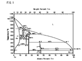
- FIG. 1 is an equilibrium diagram of a Cu—Sn alloy.
- FIG. 2A is a reflected electron image of the microstructure of the specific alloy according to the present embodiment, which was observed by SEM at a magnification of 100,000 times.
- FIG. 2B is a characteristic X-ray image (Sn-M ⁇ line) of the microstructure of the specific alloy according to the present embodiment, which was observed by SEM at a magnification of 100,000 times.
- FIG. 3 is a view showing a specific alloy manufacturing apparatus of the present embodiment.
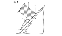
- FIG. 4 is an enlarged view of a broken line region in FIG.
- FIG. 5 is a schematic diagram for explaining the positional relationship between the tundish and the blade member in FIG. 3.
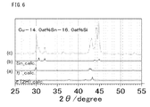
- FIG. 6 is a diagram showing a powder X-ray diffraction profile of test number 2A and a phase identification result.
- the negative electrode active material according to the present embodiment is at%, contains Sn: 10.0 to 22.5% and Si: 10.5 to 23.0%, and the balance is a chemical composition composed of Cu and impurities.
- An alloy having In the Cu—Sn binary phase diagram, the alloy has at least one of ⁇ ′ phase, ⁇ phase, and Sn phase. Moreover, the other phase which has Cu and Si as a main component may be contained.
- the microstructure of the alloy has a network region and an island region surrounded by the network region.
- the average size of the island regions is an equivalent circle diameter of 900 nm or less.
- the “negative electrode active material” referred to herein is preferably a negative electrode active material for a non-aqueous electrolyte secondary battery.
- the chemical composition further contains one or more selected from the group consisting of Ti, V, Cr, Mn, Fe, Co, Ni, Zn, Al, B, and C instead of part of Cu. May be.
- the chemical composition is Ti: 2.0% or less, V: 2.0% or less, Cr: 2.0% or less, Mn: 2.0% or less, Fe: 2.0% or less, Co: 2.0 %: Ni: 3.0% or less, Zn: 3.0% or less, Al: 3.0% or less, B: 2.0% or less, and C: 2.0% or less. 1 type (s) or 2 or more types may be contained.
- the alloy is, for example, alloy particles having an average particle diameter of median diameter (D50) of 0.1 to 45 ⁇ m.
- D50 median diameter
- the alloy particles are, for example, alloy particles having an average particle diameter of median diameter (D50) of 0.1 to 45 ⁇ m.
- the average particle diameter (D50) of the alloy particles is 0.1 ⁇ m or more, the specific surface area of the alloy particles is sufficiently small. In this case, since the alloy particles are hardly oxidized, the initial efficiency is increased.
- the average particle diameter (D50) of the alloy particles is 45 ⁇ m or less, the reaction area of the alloy particles increases. Furthermore, lithium is easily occluded and released into the alloy particles. Therefore, it is easy to obtain a sufficient discharge capacity.
- the negative electrode according to the present embodiment contains the above-described negative electrode active material.
- the battery of this embodiment includes the above-described negative electrode.
- the negative electrode active material of this embodiment includes a specific alloy (hereinafter referred to as a specific alloy).
- the chemical composition of the specific alloy contains Sn: 10.0-22.5% and Si: 10.5-23.0%, with the balance being Cu and impurities.
- Sn 10.0-22.5% If the Sn (tin) content is too low, the discharge capacity decreases. On the other hand, if the Sn content is too high, the capacity retention rate decreases. Therefore, the Sn content is Sn: 10.0-22.5%.
- the minimum with preferable Sn content is 11.0%, More preferably, it is 12.0%.
- the upper limit with preferable Sn content is 21.5%, More preferably, it is 20.5%.
- Si 10.5-23.0% If the Si (silicon) content is too low, the charge / discharge cycle characteristics deteriorate. On the other hand, if the Si content is too high, the capacity retention rate decreases. Therefore, the minimum with preferable Si content is 11.0%, More preferably, it is 11.5%. The upper limit with preferable Si content is 22.0%, More preferably, it is 21.0%.
- the specific alloy is a main component (main phase) of the negative electrode active material.
- main component means that the specific alloy in the negative electrode active material is 50% or more by volume.
- the specific alloy may contain impurities as long as the gist of the present invention is not impaired. However, it is preferable to have as few impurities as possible.
- the negative electrode active material according to the present embodiment occludes metal ions (such as lithium ions).
- the specific alloy has at least one of the ⁇ ′ phase, the ⁇ phase, and the Sn phase in the Cu—Sn binary phase diagram shown in FIG. 1 before occlusion of lithium ions.
- the specific alloy may include a phase other than the ⁇ ′ phase, the ⁇ phase, and the Sn phase.
- the phases other than the ⁇ ′ phase, the ⁇ phase, and the Sn phase are phases mainly composed of Cu and Si, for example.
- the specific alloy preferably has a composite phase including two or more selected from the group consisting of ⁇ ′ phase, ⁇ phase, and Sn phase.
- a composite phase is a phase composed of two or more different phases.
- the specific alloy includes phases other than the ⁇ ′ phase, the ⁇ phase, and the Sn phase. If a composite phase is generated, the structure becomes finer. If the structure becomes finer, the cycle characteristics increase. The reason for this is not clear, but can be considered as follows.
- Each phase of the specific alloy repeats expansion and contraction with charge and discharge. Due to the rapid volume change of each phase, a part of the phase may be detached or collapse. If the structure is refined, the distortion of the interface due to the difference in expansion / contraction rate due to storage of lithium can be reduced. Therefore, the collapse of the specific alloy can be suppressed, and the cycle characteristics are enhanced. In any one of the ⁇ ′ phase, the ⁇ phase, and the Sn phase, the structure is not refined and the cycle characteristics may be deteriorated.
- ⁇ ′ phase and ⁇ phase are equilibrium stable phases at room temperature. Both the ⁇ ′ phase and the ⁇ phase form metal ion storage sites and diffusion sites in the negative electrode active material. Therefore, the volume discharge capacity and cycle characteristics of the negative electrode active material are further improved.
- the ⁇ ′ phase, ⁇ phase, Sn phase, and alloy phase after occlusion (occlusion phase) that occlude lithium ions are also referred to as “specific alloy phase”.
- these specific alloy phases can be generated in a fine structure by a rapid solidification process described later.
- X-ray diffraction measurement is performed on the negative electrode active material to obtain measured data of the X-ray diffraction profile.
- a phase is identified based on the obtained X-ray diffraction profile (measured data).
- the phase is identified by the same method as in (1). Specifically, in a state before charging, the battery is disassembled in a glove box in an argon atmosphere, and the negative electrode is taken out from the battery. The taken-out negative electrode is wrapped in mylar foil. Thereafter, the periphery of the mylar foil is sealed with a thermocompression bonding machine. The negative electrode sealed with Mylar foil is taken out of the glove box.
- the negative electrode is attached to a non-reflective sample plate (a plate cut out so that the specific crystal plane of the silicon single crystal is parallel to the measurement plane) with a hair spray to prepare a measurement sample.
- a measurement sample is set in an X-ray diffractometer, and X-ray diffraction measurement of the measurement sample is performed to obtain an X-ray diffraction profile. Based on the obtained X-ray diffraction profile, the phase of the negative electrode active material in the negative electrode is identified.
- the battery is fully charged in a charge / discharge test apparatus.
- the fully charged battery is disassembled in the glove box, and a measurement sample is prepared by the same method as in (2).
- a measurement sample is set in an X-ray diffractometer and X-ray diffraction measurement is performed.
- the battery is completely discharged, the fully discharged battery is disassembled in the glove box, a measurement sample is prepared by the same method as (2), and X-ray diffraction measurement is performed.
- the X-ray diffraction measurement for analyzing the crystal structure change accompanying charging / discharging can also be performed by the following method.
- the coin battery before charging or before and after charging / discharging is decomposed in an inert atmosphere such as argon, and the active material mixture (negative electrode active material) applied to the negative electrode plate is collected with a spatula Remove from the foil.
- the peeled negative electrode active material is filled in an X-ray diffraction sample holder.
- the X-ray diffraction profile can be measured from different states of the crystal structure before and after charging and discharging of the negative electrode active material while eliminating the influence of the oxidizing action in the atmosphere.
- this method since diffraction lines derived from the copper foil of the current collector are excluded, there is an advantage that the diffraction lines derived from the active material can be easily identified in the analysis.
- Microstructure of specific alloy network region and island region
- the microstructure has a network region and an island region surrounded by the network region. Therefore, the distortion of the interface due to the difference in expansion and contraction due to the storage of lithium can be alleviated. Therefore, the collapse of the specific alloy can be suppressed, and the cycle characteristics are enhanced.
- the ⁇ ′ phase and the ⁇ phase can exist in both the network region and the island region.
- FIG. 2A is a reflected electron image of the microstructure of the specific alloy according to the present embodiment, which was observed by SEM at a magnification of 100,000 times.
- the black portion is an island region 10.
- the white portion in FIG. 2A is a mesh region 20.
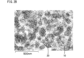
- FIG. 2B is a characteristic X-ray image (Sn-M ⁇ line) of the microstructure of the specific alloy according to the present embodiment, which was observed by SEM at a magnification of 100,000 times.
- a region having a relatively large Sn content appears brighter.
- the region having a relatively small Sn content appears darker.
- a characteristic X-ray image is obtained by mapping the intensity of the energy region of the Sn-M ⁇ ray with an energy dispersive X-ray spectroscopic detector in SEM observation described later.
- the island region 10 has a smaller Sn content than the mesh region 20.
- the mesh region 20 has a higher Sn content than the island region 10.
- the cycle characteristics are improved.
- the microstructure is a network
- the network region 20 surrounds a phase that repeats charge and discharge, and suppresses volume change (expansion and contraction) of the charge and discharge phase. Therefore, it is suppressed that a part of the phase that repeats charge and discharge is separated or collapses due to a rapid volume change of the phase that repeats charge and discharge. As a result, cycle characteristics are enhanced.
- the average size of the island-like regions 10 exceeds the equivalent circle diameter of 900 nm, a difference in expansion and contraction due to storage of lithium occurs. Therefore, distortion occurs at the interface, and the collapse of the active material particles is promoted during the charge / discharge process. Therefore, the average size of the island-like regions 10 is an equivalent circle diameter, which is 900 nm or less.
- region 10 is 700 nm or less, More preferably, it is 500 nm or less. The finer the structure, the better. However, it is not easy to make the size of the island-like region 10 less than 10 nm in manufacturing.
- the average size of the island regions 10 can be set to 900 nm or less by a rapid solidification process described later.
- the average size of the island-like region 10 in the microstructure of the specific alloy in this specification can be measured by the following method.
- Specimens with a vertical cross section are collected from the surface of a specific alloy that has been rapidly solidified by the manufacturing method described below.
- the collected test piece is embedded in a conductive resin, and the cross section (observation surface) is mirror-polished.
- An SEM image (reflected electron image) is created by photographing any three visual fields on the observation surface using a scanning electron microscope (SEM). Each field of view is 1.8 ⁇ m ⁇ 2.5 ⁇ m.
- a reflected electron image is photographed at an acceleration voltage of 5 kV using SU9000 (product model number) manufactured by Hitachi High-Technology Corporation for the SEM.
- SU9000 product model number
- the acceleration voltage is too high, the incident depth of the electron beam from the sample surface exceeds the size level of the microstructure. Therefore, reflected electron information generated from a position deeper than the size of the microstructure contributes to imaging. As a result, a clear tissue morphology cannot often be observed.
- the acceleration voltage is too low, a contaminated state of the sample surface will be observed. As a result, the original form of the tissue cannot often be observed.
- the tissue morphology is measured by image processing.
- a method for imaging and performing image processing will now be described.
- the observed microstructure is stored in an electronic file in BITMAP format or J-PEG format.
- BITMAP format 255 gray scales of black and white (zero is black and 255 corresponds to white)
- the histogram is close to the shape of the normal distribution
- the color tone in the range of at least 50 to 150 is any in the electronic image. It is preferable that these pixels are included.
- the resolution of the image is preferably set to the number of pixels of about 1280 ⁇ 960 in the vertical and horizontal directions.
- the shape of the pixel is naturally a square in real space.
- the average size of the island regions 10 surrounded by the reticulated region 20 is obtained by equivalent circle diameter conversion by image processing software.
- the image processing software includes ImageJ Ver. An example using 1.43U (software name) is shown, but other image processing software may be used as long as the same result is obtained.
- the specific procedure is as follows.
- the image processing software ImageJ has multiple types of automatic binarization functions.
- “Default” is selected as the binarization method.
- “italic intermeans” is used as the binarization method by “Default” of the image processing software ImageJ.
- “Iterative intermes” is a partial modification and change of “IsoData Algorithm”. The detailed theory of “IsoData Algorithm” can be found in IEEE TRANSACTIONS ON SYSTEMS, MAN, AND CYBERNETICS, VOL. SMC-8, NO. 8, AUGUST 1978, Picture Thresholding Using an Iterative Selection Method, T.A. W. RIDLER AND S.R. It is described in CALVARD (Non Patent Literature 1).
- each pixel is binarized into black and white with respect to a default threshold value.
- An average value of all the binarized pixels is calculated to determine whether it is lower than the default threshold value. If the average value of all pixels is lower than the default threshold, the default threshold is gradually increased and the same calculation is performed. This calculation step is repeated until the average value of all pixels is equal to the default threshold value.
- the final threshold value obtained in this way is set as the threshold value in the present embodiment.
- the pixel is reset with reference to the median when the pixel values in the region are arranged in order of magnitude. Open “Process”-“Filters”-“Median” in the menu bar, and set “Radius” to an appropriate value in the range of 1 to 10 Pixels. If normally set to 3 to 5, the boundary between the mesh region 20 and the island region 10 surrounded by the mesh region 20 can be clarified, and the analysis of the tissue morphology becomes easy.
- the number of island regions 10 surrounded by the mesh region 20 and corresponding to the darker color tone is desirably 200 or more from a statistical standpoint. If it is less than this, the number of observation fields is increased for analysis.
- the specific alloy can have at least one of the ⁇ ′ phase, the ⁇ phase, and the Sn phase
- the chemical composition of the specific alloy can be Ti, V, Cr, Mn instead of a part of Cu.
- Fe, Co, Ni, Zn, Al, B, and C may be included.
- the chemical composition is Ti: 2.0% or less, V: 2.0% or less, Cr: 2.0% or less, Mn: 2.0% or less, Fe: 2.0% or less, Co: Group consisting of 2.0% or less, Ni: 3.0% or less, Zn: 3.0% or less, Al: 3.0% or less, B: 2.0% or less, and C: 2.0% or less 1 type or 2 types or more selected from.
- Ti, V, Cr, Mn, Fe, Co, Ni, Zn, Al, B, and C are optional elements.
- the preferable upper limit of the Ti content is 2.0% as described above.
- a more preferable upper limit of the Ti content is 1.0%, and more preferably 0.5%.
- the minimum with preferable Ti content is 0.01%, More preferably, it is 0.05%, More preferably, it is 0.1%.
- the preferable upper limit of the V content is 2.0% as described above.
- the upper limit with more preferable V content is 1.0%, More preferably, it is 0.5%.
- the minimum with preferable V content is 0.01%, More preferably, it is 0.05%, More preferably, it is 0.1%.
- the preferable upper limit of the Cr content is 2.0% as described above.
- a more preferable upper limit of the Cr content is 1.0%, and more preferably 0.5%.
- the minimum with preferable Cr content is 0.01%, More preferably, it is 0.05%, More preferably, it is 0.1%.
- the preferable upper limit of the Mn content is 2.0% as described above.
- the upper limit with more preferable Mn content is 1.0%, More preferably, it is 0.5%.
- the minimum with preferable Mn content is 0.01%, More preferably, it is 0.05%, More preferably, it is 0.1%.
- the preferable upper limit of the Fe content is 2.0% as described above.
- a more preferable upper limit of the Fe content is 1.0%, and more preferably 0.5%.
- the minimum with preferable Fe content is 0.01%, More preferably, it is 0.05%, More preferably, it is 0.1%.
- the preferable upper limit of the Co content is 2.0% as described above.
- a more preferable upper limit of the Co content is 1.0%, and more preferably 0.5%.
- the minimum with preferable Co content is 0.01%, More preferably, it is 0.05%, More preferably, it is 0.1%.
- the preferable upper limit of the Ni content is 3.0% as described above. A more preferable upper limit of the Ni content is 2.0%. A preferable lower limit of the Ni content is 0.1%.
- the preferable upper limit of the Zn content is 3.0% as described above. A more preferable upper limit of the Zn content is 2.0%.
- the minimum with preferable Zn content is 0.1%, More preferably, it is 0.5%, More preferably, it is 1.0%.
- the preferable upper limit of the Al content is 3.0% as described above.
- the upper limit with more preferable Al content is 2.0%, More preferably, it is 1.0%.
- the minimum with preferable Al content is 0.1%, More preferably, it is 0.5%, More preferably, it is 1.0%.
- the preferable upper limit of B content is 2.0%.
- a more preferable upper limit of the B content is 1.0%, and more preferably 0.5%.
- the minimum with preferable B content is 0.01%, More preferably, it is 0.05%, More preferably, it is 0.1%.
- the preferable upper limit of the C content is 2.0%.
- the upper limit with more preferable C content is 1.0%, More preferably, it is 0.5%.
- the minimum with preferable C content is 0.01%, More preferably, it is 0.05%, More preferably, it is 0.1%.
- the specific alloy is preferably an alloy particle having an average particle diameter of 0.1 to 45 ⁇ m in median diameter (hereinafter also referred to as “specific alloy particle”).
- the particle diameter of the specific alloy particles affects the discharge capacity of the battery. The smaller the particle size, the better. This is because if the particle diameter is small, the total area of the negative electrode active material contained in the negative electrode plate can be increased. Therefore, the average particle diameter of the specific alloy particles is preferably 45 ⁇ m or less in terms of median diameter (D50). In this case, the reaction area of the particles increases. Furthermore, lithium is easily occluded and released to the inside of the particle. Therefore, it is easy to obtain a sufficient discharge capacity.
- a preferable average particle diameter of the specific alloy particles is 0.1 to 45 ⁇ m in median diameter (D50).
- the preferable lower limit of the average particle diameter (D50) is 0.4 ⁇ m, more preferably 1.0 ⁇ m.
- the upper limit with a preferable average particle diameter (D50) is 40 micrometers, More preferably, it is 35 micrometers.
- the average particle size can be measured as follows. When the average particle diameter is 0.5 ⁇ m or more in terms of median diameter (D50), the average particle diameter is determined by an airflow high-speed moving image analysis method. For the analysis, the product name: Camsizer X manufactured by Vander Scientific is used.
- the average particle diameter is less than 0.5 ⁇ m in median diameter (D50), it is measured using a laser particle size distribution meter.
- D50 median diameter
- the laser particle size distribution meter a trade name: Microtrack particle size distribution meter manufactured by Nikkiso Co., Ltd. is used.
- the negative electrode active material described above may contain materials other than the specific alloy.
- the negative electrode active material may contain graphite as an active material together with the specific alloy.
- the method for producing a negative electrode active material material includes a step of preparing a molten metal (preparation step) and a step of rapidly cooling the molten metal to manufacture an alloy ribbon (alloy ribbon manufacturing step).
- a molten metal having the chemical composition is manufactured.
- the molten metal is produced by melting raw materials by a known melting method such as arc melting or resistance heating melting.
- the molten metal temperature is preferably 800 ° C. or higher.
- the molten metal is rapidly solidified.
- the ⁇ ′ phase, ⁇ phase, and Sn phase which are equilibrium phases, form a fine solidified structure and are brought to room temperature.
- the rapid solidification method include a strip casting method and a melt spin method. In the present embodiment, the strip casting method will be described as an example.
- the alloy ribbon 6 is manufactured using the manufacturing apparatus shown in FIG.
- the manufacturing apparatus 1 includes a cooling roll 2, a tundish 4, and a blade member 5.
- the negative electrode active material manufacturing method of the present embodiment is, for example, a strip casting (SC) method including the blade member 5.
- the cooling roll 2 has an outer peripheral surface, and cools and solidifies the molten metal 3 on the outer peripheral surface while rotating.
- the cooling roll 2 includes a cylindrical body portion and a shaft portion (not shown).
- drum has the said outer peripheral surface.
- the shaft portion is disposed at the central axis position of the body portion and is attached to a drive source (not shown).
- the cooling roll 2 rotates around the central axis 9 of the cooling roll 2 by a driving source.
- the material of the cooling roll 2 is a material having high hardness and thermal conductivity.
- the material of the cooling roll 2 is, for example, copper or a copper alloy.
- the material of the cooling roll 2 is copper.
- the cooling roll 2 may further have a coating on the surface. Thereby, the hardness of the cooling roll 2 increases.
- the coating is, for example, a plating coating or a cermet coating.
- the plating film is, for example, chromium plating or nickel plating.
- Cermet coatings include, for example, tungsten (W), cobalt (Co), titanium (Ti), chromium (Cr), nickel (Ni), silicon (Si), aluminum (Al), boron (B), and these elements 1 type (s) or 2 or more types selected from the group consisting of carbides, nitrides and carbonitrides.
- the surface layer of the cooling roll 2 is copper, and the cooling roll 2 further has a chromium plating film on the surface.
- X shown in FIG. 3 is the rotation direction of the cooling roll 2.
- the cooling roll 2 rotates in a certain direction X.
- the molten metal 3 in contact with the cooling roll 2 partially solidifies on the outer peripheral surface of the cooling roll 2, and moves with the rotation of the cooling roll 2.
- the roll peripheral speed of the cooling roll 2 is appropriately set in consideration of the cooling speed and manufacturing efficiency of the molten metal 3. If the roll peripheral speed is slow, the production efficiency decreases. If the roll peripheral speed is fast, the alloy ribbon 6 tends to peel from the outer peripheral surface of the cooling roll 2. Therefore, the time during which the alloy ribbon 6 is in contact with the outer peripheral surface of the cooling roll 2 is shortened. In this case, the alloy ribbon 6 is not cooled by the cooling roll 2 but is cooled by air. When air-cooled, a sufficient cooling rate cannot be obtained. Therefore, a fine microstructure cannot be obtained, the island regions 10 and the network regions 20 cannot be obtained, and / or the average size of the island regions 10 may exceed 900 nm.
- the lower limit of the roll peripheral speed is preferably 50 m / min, more preferably 80 m / min, and still more preferably 120 m / min.
- the upper limit of the roll peripheral speed is not particularly limited, but is, for example, 500 m / min in consideration of the facility capacity.
- the roll peripheral speed can be obtained from the roll diameter and the rotation speed.
- the inside of the cooling roll 2 may be filled with a heat removal solvent. Thereby, the molten metal 3 can be cooled efficiently.
- a solvent is 1 type, or 2 or more types selected from the group which consists of water, an organic solvent, and oil, for example.
- the solvent may stay inside the cooling roll 2 or may be circulated to the outside.
- the tundish 4 can store the molten metal 3 and supplies the molten metal 3 on the outer peripheral surface of the cooling roll 2.
- the shape of the tundish 4 is not particularly limited as long as the molten metal 3 can be supplied onto the outer peripheral surface of the cooling roll 2.
- the shape of the tundish 4 may be a box shape with an open top as shown in FIG. 3, or may be another shape.
- the tundish 4 includes a supply end 7 that guides the molten metal 3 on the outer peripheral surface of the cooling roll 2.
- the molten metal 3 is supplied from the crucible (not shown) to the tundish 4, and then supplied to the outer peripheral surface of the cooling roll 2 through the supply end 7.
- the shape of the supply end 7 is not particularly limited.
- the cross section of the supply end 7 may be rectangular as shown in FIG. 3, or may be inclined. Alternatively, the supply end 7 may have a nozzle shape.
- the tundish 4 is disposed in the vicinity of the outer peripheral surface of the cooling roll 2.
- the molten metal 3 can be stably supplied on the outer peripheral surface of the cooling roll 2.
- the gap between the tundish 4 and the cooling roll 2 is set as appropriate as long as the molten metal 3 does not leak.
- the material of the tundish 4 is preferably a refractory material.
- the tundish 4 is, for example, aluminum oxide (Al 2 O 3 ), silicon monoxide (SiO), silicon dioxide (SiO 2 ), chromium oxide (Cr 2 O 3 ), magnesium oxide (MgO), titanium oxide (TiO 2 ). And one or more selected from the group consisting of aluminum titanate (Al 2 TiO 5 ) and zirconium oxide (ZrO 2 ).
- the blade member 5 is disposed downstream of the tundish 4 in the rotation direction of the cooling roll 2 with a gap between the blade member 5 and the outer peripheral surface of the cooling roll 2.
- the blade member 5 is, for example, a plate-like member disposed in parallel with the axial direction of the cooling roll 2.
- FIG. 4 is an enlarged cross-sectional view of the vicinity of the tip of the blade member 5 of the manufacturing apparatus 1 (the range surrounded by the broken line in FIG. 3).
- blade member 5 is disposed with a gap A between the outer peripheral surface of cooling roll 2.
- the blade member 5 regulates the thickness of the molten metal 3 on the outer peripheral surface of the cooling roll 2 to the width of the gap A between the outer peripheral surface of the cooling roll 2 and the blade member 5.
- the molten metal 3 upstream of the blade member 5 in the rotation direction of the cooling roll 2 may be thicker than the width of the gap A. In this case, the molten metal 3 corresponding to the thickness exceeding the width of the gap A is blocked by the blade member 5.
- the thickness of the molten metal 3 is reduced to the width of the gap A.
- the cooling rate of the molten metal 3 is increased. For this reason, the structure becomes finer. Thereby, a specific alloy phase can be produced
- the width of the gap A is preferably narrower than the blade member 5 than the thickness B of the molten metal 3 on the outer peripheral surface on the upstream side in the rotation direction of the cooling roll 2.
- the molten metal 3 on the outer peripheral surface of the cooling roll 2 becomes thinner. Therefore, the cooling rate of the molten metal 3 is further increased. As a result, the structure becomes finer. Thereby, a specific alloy phase can be produced
- the width of the gap A between the outer peripheral surface of the cooling roll 2 and the blade member 5 is the shortest distance between the blade member 5 and the outer peripheral surface of the cooling roll 2.
- the width of the gap A is appropriately set according to the intended cooling rate and production efficiency. The narrower the gap A, the thinner the molten metal 3 after thickness adjustment. For this reason, the cooling rate of the molten metal 3 is further increased. As a result, the structure can be easily refined. Therefore, the upper limit of the gap A is preferably 100 ⁇ m, more preferably 50 ⁇ m.
- the distance between the point where the molten metal 3 is supplied from the tundish 4 and the point where the blade member 5 is disposed on the outer peripheral surface of the cooling roll 2 is appropriately set.
- the blade member 5 may be disposed within a range where the free surface of the molten metal 3 (the surface on the side where the molten metal 3 is not in contact with the cooling roll 2) is in contact with the blade member 5 in a liquid or semi-solid state.
- FIG. 5 is a view showing the mounting angle of the blade member 5.
- blade member 5 includes a surface PL ⁇ b> 1 including central axis 9 and supply end 7 of cooling roll 2, and a surface including central axis 9 of cooling roll 2 and the tip of blade member 5.
- the angle ⁇ formed by PL2 is arranged to be constant (hereinafter, this angle ⁇ is referred to as a mounting angle ⁇ ).
- the attachment angle ⁇ can be set as appropriate.
- the upper limit of the attachment angle ⁇ is 45 °, for example.
- the upper limit of the attachment angle ⁇ is preferably 30 °.
- the lower limit of the attachment angle ⁇ is not particularly limited, but is preferably in a range where the blade member 5 does not directly contact the molten metal 3 on the tundish 4.
- the blade member 5 preferably has a heat removal surface 8.
- the heat removal surface 8 is disposed to face the outer peripheral surface of the cooling roll 2.
- the heat removal surface 8 is in contact with the molten metal 3 that passes through the gap between the outer peripheral surface of the cooling roll 2 and the blade member 5.
- the material of the blade member 5 is preferably a refractory material.
- the blade member 5 is, for example, aluminum oxide (Al 2 O 3 ), silicon monoxide (SiO), silicon dioxide (SiO 2 ), chromium oxide (Cr 2 O 3 ), magnesium oxide (MgO), titanium oxide (TiO 2 ). And one or more selected from the group consisting of aluminum titanate (Al 2 TiO 5 ) and zirconium oxide (ZrO 2 ).
- the blade member 5 is one or two selected from the group consisting of aluminum oxide (Al 2 O 3 ), silicon dioxide (SiO 2 ), aluminum titanate (Al 2 TiO 5 ), and magnesium oxide (MgO). Contains more than seeds.
- a plurality of blade members 5 may be continuously arranged in the rotation direction of the cooling roll 2. In this case, the burden on one blade member 5 is reduced. Furthermore, the accuracy of the thickness of the molten metal 3 can be increased.
- the thickness of the molten metal 3 on the outer peripheral surface of the cooling roll 2 is regulated by the blade member 5. Therefore, the molten metal 3 on the outer peripheral surface of the cooling roll 2 becomes thin. As the molten metal 3 becomes thinner, the cooling rate of the molten metal 3 increases. Therefore, if an alloy ribbon is manufactured using the manufacturing apparatus 1, the alloy ribbon 6 having a more specific alloy phase can be manufactured.
- the thickness of the molten metal 3 on the outer peripheral surface of the cooling roll 2 cannot be regulated thinly. In this case, the cooling rate of the molten metal 3 decreases. Therefore, even if the MG treatment described later is performed, the alloy ribbon 6 having a fine microstructure cannot be obtained. That is, the island regions 10 and the mesh regions 20 cannot be obtained, and / or the average size of the island regions 10 exceeds 900 nm.
- the roll peripheral speed of the cooling roll 2 needs to be increased in order to reduce the thickness of the molten metal 3 on the outer peripheral surface of the cooling roll 2. . If the roll peripheral speed is fast, the alloy ribbon 6 peels off from the outer peripheral surface of the cooling roll 2 quickly. That is, the time during which the alloy ribbon 6 is in contact with the outer peripheral surface of the cooling roll 2 is shortened. In this case, the alloy ribbon 6 is not cooled by the cooling roll 2 but is cooled by air. When air-cooled, a sufficient average cooling rate cannot be obtained. Therefore, the alloy ribbon 6 having a fine microstructure cannot be obtained. That is, the island regions 10 and the mesh regions 20 cannot be obtained, and / or the average size of the island regions 10 exceeds 900 nm.
- a mechanical grinding (MG) process may be performed on the alloy ribbon 6 manufactured using the manufacturing apparatus 1. Thereby, the average particle diameter (D50) of the specific alloy manufactured by the rapid solidification process can be further reduced.
- Mechanical grinding (MG) processing includes the following steps. First, the specific alloy ribbon is introduced into an MG device such as an attritor or a vibration ball mill together with the balls. An additive for preventing granulation may be added to the MG device together with the balls.
- an MG device such as an attritor or a vibration ball mill together with the balls.
- An additive for preventing granulation may be added to the MG device together with the balls.
- the specific alloy ribbon in the MG device is repeatedly pulverized with high energy and the specific alloy particles formed by the pulverization are pressed together.
- specific alloy particles having a median diameter of 0.1 to 45 ⁇ m and an average particle diameter (D50) are produced.
- MG equipment is, for example, a high-speed planetary mill.
- An example of a high-speed planetary mill is the trade name “Hiji BX” manufactured by Kurimoto Steel Works.
- the preferable manufacturing conditions in the MG apparatus are as follows.
- a preferable ball ratio is 5 to 80.
- a more preferred lower limit of the ball ratio is 10, more preferably 12.
- a more preferable upper limit of the ball ratio is 60, and more preferably 40.
- SUJ2 defined by the JIS standard is used as the ball material.
- the diameter of the ball is, for example, 0.8 mm to 10 mm.
- a preferred MG treatment time is 1 to 48 hours.
- the preferable lower limit of the MG treatment time is 2 hours, and more preferably 4 hours.
- the upper limit with the preferable MG processing time is 36 hours, More preferably, it is 24 hours. Note that the unit stop time described later is not included in the MG processing time.
- Cooling condition during MG treatment Stop for 30 minutes or more per 3 hours of MG treatment (intermittent operation) If the temperature of the specific alloy during MG treatment becomes too high, the average particle size will increase.
- the preferred temperature of chiller cooling water for equipment during MG treatment is 1-25 ° C.
- the total stop time per 3 hours of MG processing (hereinafter referred to as unit stop time) is set to 30 minutes or more.
- unit stop time is set to 30 minutes or more.
- polyvinyl pyrrolidone can be added as an additive for preventing granulation.
- a preferable addition amount of PVP is 0.5 to 8% by mass, and more preferably 2 to 5% by mass with respect to the mass of the specific alloy ribbon (raw material). If the amount is within the above range, the average particle size of the specific alloy can be easily adjusted to an appropriate range, and the average particle size of the specific alloy particles can be easily adjusted to 0.1 to 45 ⁇ m in terms of median diameter (D50). Become. However, in the MG treatment, the average particle diameter (D50) of the specific alloy can be adjusted to the above range without adding an additive.
- the specific alloy is manufactured by the above process. If necessary, another active material (graphite) is mixed with the specific alloy.
- the negative electrode active material is manufactured through the above steps.
- the negative electrode active material may be composed of a specific alloy and impurities, or may contain a specific alloy and another active material (for example, graphite).
- the negative electrode using the negative electrode active material according to the present embodiment can be manufactured by, for example, the following well-known method.
- a mixture in which a binder such as polyvinylidene fluoride (PVDF), polymethyl methacrylate (PMMA), polytetrafluoroethylene (PTFE), styrene butadiene rubber (SBR) is mixed with the negative electrode active material is manufactured.
- a carbon material powder such as natural graphite, artificial graphite or acetylene black is mixed with this mixture to produce a negative electrode mixture.
- a solvent such as N-methylpyrrolidone (NMP), dimethylformamide (DMF), or water is added to dissolve the binder, and if necessary, the mixture is sufficiently stirred using a homogenizer and glass beads to remove the negative electrode mixture. Shape.
- NMP N-methylpyrrolidone
- DMF dimethylformamide
- This slurry is applied to a support such as rolled copper foil or electrodeposited copper foil and dried. Thereafter, the dried product is pressed.
- a negative electrode is manufactured by the above process.
- the binder is preferably 1 to 10% by mass with respect to the total amount of the negative electrode mixture from the viewpoint of the mechanical strength of the negative electrode and battery characteristics.
- the support is not limited to copper foil.
- the support may be, for example, a thin foil of another metal such as stainless steel or nickel, a net-like sheet punching plate, a mesh knitted with a metal wire, or the like.
- the nonaqueous electrolyte secondary battery according to the present embodiment includes the above-described negative electrode, positive electrode, separator, and electrolytic solution or electrolyte.
- the shape of the battery may be a cylindrical shape, a square shape, a coin shape, a sheet shape, or the like.
- the battery of this embodiment may be a battery using a solid electrolyte such as a polymer battery.
- the positive electrode of the battery of this embodiment preferably contains a lithium (Li) -containing transition metal compound as an active material.
- the Li-containing transition metal compound is, for example, LiM 1-x M ′ x O 2 or LiM 2 yM′O 4 .
- M and M ′ are barium (Ba), cobalt (Co), nickel (Ni), manganese (Mn), chromium (Cr), titanium (Ti), respectively.
- the battery of this embodiment includes a transition metal chalcogenide; vanadium oxide and its lithium (Li) compound; niobium oxide and its lithium compound; a conjugated polymer using an organic conductive material; a sheprel phase compound; activated carbon; Other positive electrode materials such as fibers may be used.
- the battery electrolyte of the present embodiment is generally a non-aqueous electrolyte obtained by dissolving a lithium salt as a supporting electrolyte in an organic solvent.
- the lithium salt include LiClO 4 , LiBF 4 , LiPF 6 , LiAsF 6 , LiB (C 6 H 5 ), LiCF 3 SO 3 , LiCH 3 SO 3 , Li (CF 3 SO 2 ) 2 N, LiC 4 F 9 SO 3 , Li (CF 2 SO 2 ) 2 , LiCl, LiBr, LiI or the like. These may be used alone or in combination of two or more.
- the organic solvent is preferably a carbonic acid ester such as propylene carbonate, ethylene carbonate, ethyl methyl carbonate, dimethyl carbonate, or diethyl carbonate.
- a carbonic acid ester such as propylene carbonate, ethylene carbonate, ethyl methyl carbonate, dimethyl carbonate, or diethyl carbonate.
- various other organic solvents including carboxylic acid esters and ethers can also be used. These organic solvents may be used independently and may be used in combination of 2 or more type.
- the separator is installed between the positive electrode and the negative electrode.
- the separator serves as an insulator. Further, the separator greatly contributes to the retention of the electrolyte.
- the battery of this embodiment may be provided with a known separator.
- the separator is, for example, a polyolefin material such as polypropylene, polyethylene, a mixed cloth of both, or a porous body such as a glass filter.
- a battery is manufactured by enclosing the above-described negative electrode, positive electrode, separator, and electrolyte or electrolyte in a battery container.
- the negative electrode active material, the negative electrode, and the battery of the present embodiment will be described in more detail using examples. Note that the negative electrode active material, the negative electrode, and the battery of the present embodiment are not limited to the following examples.
- the metal particles, negative electrode active material, negative electrode, and coin battery of test numbers 1 to 32 shown in Table 1 were manufactured.
- the change in the X-ray profile due to charging / discharging of the metal particles of each test number was confirmed, and the crystal structure (generated phase) was specified.
- the initial discharge capacity (discharge capacity per volume) of the battery, the discharge capacity at 100 cycles, and the capacity maintenance rate were investigated.
- the metal particles, the negative electrode active material, the negative electrode, and the coin battery for each test number were manufactured as follows.
- the molten metal was manufactured such that the chemical composition of the particulate metal particles other than test number 23 was the chemical composition shown in Table 1.
- the chemical composition of the powdered metal particles is Cu-12.0% Sn-14.0% Si, that is, 12.0% Sn and 14.0%.
- the molten metal was manufactured so as to contain Si and the balance being Cu and impurities.
- the molten metal was produced by high-frequency melting a raw material containing a metal (unit: g) shown in the “molten raw material” column of Table 1.
- melt temperature was stabilized at 1200 ° C., and then an alloy ribbon was cast under the solidification cooling conditions described in Table 2.
- solidification cooling method condition is as follows.
- SC condition 1 strip casting (SC) was performed in the above-described embodiment to limit the pulled-up thickness of the molten metal using the blade member.
- SC strip casting
- the molten metal was quenched to cast an alloy ribbon having a thickness of 70 ⁇ m.
- a water-cooled copper cooling roll was used.
- the rotation speed of the cooling roll was 300 meters per minute as the peripheral speed of the roll surface.
- the above-described molten metal was supplied to a rotating water-cooled roll through a horizontal tundish (made of alumina) in an argon atmosphere.
- the molten metal was rapidly solidified by being pulled up to a rotating water cooling roll.
- the width of the gap between the blade member and the water cooling roll was 70 ⁇ m.
- the blade member was made of alumina.
- SC condition 2 In SC condition 2, SC was performed without using a blade member. That is, in SC condition 2, an alloy ribbon was manufactured by the conventional SC method. By this SC method, the molten metal was quenched to cast an alloy ribbon having a thickness of 40 ⁇ m. Specifically, a water-cooled copper cooling roll was used. The rotation speed of the cooling roll was 600 meters per minute as the peripheral speed of the roll surface. The above-described molten metal was supplied to a rotating water-cooled roll through a horizontal tundish (made of alumina) in an argon atmosphere. The molten metal was rapidly solidified by being pulled up to a rotating water cooling roll.
- SC condition 3 In SC condition 3, SC was performed without using a blade member. That is, in SC condition 3, an alloy ribbon was manufactured by the conventional SC method. By this SC method, the molten metal was quenched to cast an alloy ribbon having a thickness of 200 ⁇ m. Specifically, a water-cooled copper cooling roll was used. The rotational speed of the cooling roll was set to 70 meters per minute as the peripheral speed of the roll surface. The above-described molten metal was supplied to a rotating water-cooled roll through a horizontal tundish (made of alumina) in an argon atmosphere. The molten metal was rapidly solidified by being pulled up to a rotating water cooling roll.
- the molten metal temperature was stabilized at 1200 ° C., and then an alloy ingot was cast.
- the alloy ribbon manufactured with the test number other than the test number 2D and the ingot with the test number 2C were pulverized using a mixer mill. Specifically, the alloy ribbon was pulverized using a mixer mill (apparatus model number: MM400) manufactured by Vander Scientific.
- the crushed container was made of stainless steel having an internal volume of 25 cm 3 . Two balls having the same material as that of the pulverization vessel and having a diameter of 15 mm and 3 g of a quenched foil strip or ingot were added, and the setting value of the frequency was set to 25 rps, and the operation was performed for 600 seconds to produce metal particles.
- the produced alloy ribbon was pulverized using a mixer mill. Specifically, the alloy ribbon was pulverized using a mixer mill (apparatus model number: MM400) manufactured by Vander Scientific.
- the crushed container was made of stainless steel having an internal volume of 25 cm 3 .
- One ball having a diameter of 10 mm and a quenching foil strip of 3 g were charged in the same material as that of the pulverization vessel, and the setting value of the frequency was set to 25 rps, and the operation was performed for 30 seconds to produce metal particles.
- MG treatment was further performed on the metal particles of test number 2B.
- the alloy ribbon, graphite powder (average particle diameter is 5 ⁇ m in median diameter (D50)), and PVP were mixed at a ratio of 90: 6: 4.
- the mixture was subjected to MG treatment in an argon gas atmosphere using a high-speed planetary mill (trade name Hiji BX, manufactured by Kurimoto Steel Works).
- MG treatment was performed while cooling with a chiller.
- the cooling water temperature of the chiller was 10 ° C.
- test number 23 a bulk of pure silicon was prepared as a raw material.
- the bulk was pulverized using a mixer mill to produce Si powder particles.
- the average particle diameter (D50) (median diameter) of the Si powder particles was 15.0 ⁇ m.
- the manufactured Si powder particles were used as metal particles of test number 23.
- X-ray diffraction measurement was performed on the metal particles after pulverization and before MG treatment to obtain measured data of the X-ray diffraction profile. Specifically, an X-ray diffraction profile of the powder of the negative electrode active material was obtained using Rigaku SmartLab (rotor target maximum output 9 KW; 45 kV-200 mA). Based on the obtained X-ray diffraction profile (measured data), the constituent phases of the metal particles were identified. The X-ray diffractometer and measurement conditions were as follows.
- the analysis method of the crystal structure will be described below by taking the analysis of the metal particle of test number 2A as an example.
- FIG. 6 is a diagram showing a powder X-ray diffraction profile of test number 2A and a phase identification result.
- (A) and (b) in FIG. 6 are diffraction lines of ⁇ ′ phase and Sn single phase, respectively.
- the diffraction peaks of the actually measured X-ray diffraction profile ((c) in the figure) mainly coincided with the diffraction lines of (a) and (b). Therefore, it was identified that the metal particles (negative electrode active material) of test number 2A mainly contain the ⁇ ′ phase and the Sn phase. In addition to these phases, as shown in FIG. 6, the generation of unidentified other phases was also observed.
- the crystal structure was specified by the same method (displayed in Table 2).
- ⁇ ′, Sn, and ⁇ in the main generated phase column indicate ⁇ ′ phase, Sn phase, and ⁇ phase, respectively.
- the average size of the island regions 10 was determined by the method described above using a product model number: SU9000 manufactured by Hitachi High-Technology Corporation. Table 2 shows the obtained results.
- the powder particle size distribution of the metal particles (test number 2B) produced by carrying out MG treatment after the pulverization treatment was measured with a laser particle size distribution meter (Microtrac particle size distribution meter manufactured by Nikkiso Co., Ltd.). Based on the measured powder particle size distribution, the average particle size (D50) was determined. Table 2 shows the obtained results.
- a negative electrode mixture slurry containing the above metal particles as a negative electrode active material and containing a negative electrode active material was produced. Specifically, powdered metal particles, acetylene black (AB) as a conductive additive, styrene butadiene rubber (SBR) (double dilution) as a binder, and carboxymethyl cellulose (CMC) as a thickener. ) In a mass ratio of 75: 15: 10: 5 (mixing amount is 1 g: 0.2 g: 0.134 g: 0.067 g).
- distilled water was added to the mixture so that the slurry concentration was 27.2% to produce a negative electrode mixture slurry. Since the styrene butadiene rubber used was diluted twice with water, 0.134 g of styrene butadiene rubber was blended for weighing.
- the produced negative electrode mixture slurry was applied onto a copper foil using an applicator (150 ⁇ m).
- the copper foil coated with the slurry was dried at 100 ° C. for 20 minutes.
- the copper foil after drying had a coating film made of a negative electrode active material film on the surface.
- the copper foil having the negative electrode active material film was punched to produce a disc-shaped copper foil having a diameter of 13 mm.
- the copper foil after punching was pressed with a press pressure of 500 kgf / cm 2 to produce a plate-like negative electrode.
- a manufactured negative electrode, EC-DMC-EMC-VC-FEC as an electrolytic solution, a polyolefin separator ( ⁇ 17 mm) as a separator, and plate-like metal Li ( ⁇ 19 ⁇ 1 mmt) as a positive electrode material were prepared.
- a 2016-type coin battery was manufactured using the prepared negative electrode material, electrolytic solution, separator, and positive electrode material. The coin battery was assembled in a glove box in an argon atmosphere.
- Doping capacity and dedoping capacity correspond to charge capacity and discharge capacity when this electrode is used as a negative electrode of a lithium ion secondary battery. Therefore, the measured dedoping capacity was defined as “discharge capacity”.
- the charge and discharge were repeated for the coin battery. For each charge and discharge in each cycle, the doping capacity and the dedoping capacity were measured. Using the measurement results, charge / discharge cycle characteristics were obtained. Specifically, the discharge capacity (mAh / cm 3 ) at the first cycle (first time) was determined.
- the discharge capacity (mAh / cm 3 ) after 100 cycles and the capacity retention rate were determined.
- the capacity maintenance rate was expressed as a percentage obtained by dividing the discharge capacity after 100 cycles by the initial discharge capacity.
- the capacity of the coin battery was calculated as a value converted into the capacity of a single alloy by subtracting the capacity of the conductive auxiliary agent (acetylene black: AB) and then dividing by the ratio of the alloy in the negative electrode mixture.
- the chemical compositions of the metal particles of test numbers 1, 2A, 2B, 2D, 3 to 22, and 28 are appropriate, and are at least one of ⁇ ′ phase, ⁇ phase, and Sn phase.
- the phase of was included.
- generation of an unidentified other phase was also observed.
- the average size of the island-like regions 10 in the microstructure was 900 nm or less.
- the discharge capacity was higher than the theoretical capacity of graphite (833 mAh / cm 3 ) both at the first time and after 100 cycles.
- the capacity retention ratios were all 50% or more.
- test number 2C had an appropriate chemical composition and contained a ⁇ ′ phase and an ⁇ phase.
- the ingot was pulverized with a mixer mill, the average size of the island-like regions 10 in the microstructure exceeded 900 nm.
- the discharge capacity after 100 cycles was lower than the theoretical capacity of graphite.
- the capacity retention rate was as low as less than 50%.
- Test No. 2E had an appropriate chemical composition and contained a ⁇ ′ phase and an ⁇ phase, but the average size of the island-like regions 10 in the microstructure exceeded 900 nm. As a result, the capacity retention rate was as low as less than 50%. In Test No. 2E, SC that did not use a blade member was performed, and the roll peripheral speed was too high, so that it could not be cooled sufficiently and the average size of the island-like regions 10 in the microstructure exceeded 900 nm.
- Test No. 2F had an appropriate chemical composition and contained a ⁇ ′ phase and an ⁇ phase, but the average size of the island-like regions 10 in the microstructure exceeded 900 nm. As a result, the discharge capacity after 100 cycles was lower than the theoretical capacity of graphite. Furthermore, the capacity retention rate was as low as less than 50%. In Test No. 2F, SC without using a blade member was performed, and the roll peripheral speed was too slow, so that the alloy ribbon was too thick and the average size of the island-like regions 10 in the microstructure exceeded 900 nm.
- the chemical composition was not appropriate. Therefore, the crystal structure of these metal particles did not contain any of the ⁇ ′ phase, the ⁇ phase, and the Sn phase, or the average size of the island-like regions 10 in the microstructure exceeded 900 nm.
- the ⁇ ′ phase and the ⁇ phase were mainly, but the average size of the island-like regions 10 in the microstructure exceeded 900 nm. As a result, the capacity retention rate was as low as less than 50%. This is presumably because the ⁇ phase and ⁇ ′ phase, which are Cu—Sn binary equilibrium phases, formed a coarse composite structure due to the low Si content.
- test number 25 the other phase was unidentified. As a result, the capacity retention rate was as low as less than 50%.
- the main component was a Cu—Si based compound phase.
- the discharge capacity was lower than the theoretical capacity of graphite.
- the crystal structure of the metal particle of test number 27 was estimated to be a solid solution of Cu. As a result, the discharge capacity was lower than the theoretical capacity of graphite.
- test number 29 the unidentified other phase was mainly used. As a result, the capacity retention rate was as low as less than 50%.
- the crystal structure of the metal particle of Test No. 30 was presumed to be mainly a solid solution of Cu and an unidentified other phase. As a result, the discharge capacity was lower than the theoretical capacity of graphite.
- the crystal structure of the metal particle of test number 31 was presumed to be mainly a solid solution of Cu and an unidentified other phase. As a result, the discharge capacity was lower than the theoretical capacity of graphite.
- the crystal structure of the metal particles of the test number 32 was mainly ⁇ ′ phase and Sn phase, but the average size of the island-like regions 10 in the microstructure exceeded 900 nm. As a result, the capacity retention rate was as low as less than 50%. This is presumably because the Sn content and the ⁇ ′ phase, which is the Cu—Sn binary equilibrium phase, formed a coarse composite structure because the Sn content was too high.
Landscapes
- Chemical & Material Sciences (AREA)
- Engineering & Computer Science (AREA)
- Chemical Kinetics & Catalysis (AREA)
- General Chemical & Material Sciences (AREA)
- Electrochemistry (AREA)
- Materials Engineering (AREA)
- Mechanical Engineering (AREA)
- Organic Chemistry (AREA)
- Metallurgy (AREA)
- Manufacturing & Machinery (AREA)
- Inorganic Chemistry (AREA)
- Battery Electrode And Active Subsutance (AREA)
- Powder Metallurgy (AREA)
Abstract
Description
本実施形態の負極活物質材料は、特定の合金(以下、特定合金という)を含む。特定合金の化学組成は、Sn:10.0~22.5%、及び、Si:10.5~23.0%を含有し、残部はCu及び不純物からなる。
Sn(スズ)含有量が低すぎれば、放電容量が低下する。一方、Sn含有量が高すぎれば、容量維持率が低下する。したがって、Sn含有量は、Sn:10.0~22.5%である。Sn含有量の好ましい下限は11.0%であり、さらに好ましくは、12.0%である。Sn含有量の好ましい上限は、21.5%であり、さらに好ましくは20.5%である。
Si(シリコン)含有量が低すぎれば、充放電サイクル特性が低下する。一方、Si含有量が高すぎれば、容量維持率が低下する。したがって、Si含有量の好ましい下限は11.0%であり、さらに好ましくは、11.5%である。Si含有量の好ましい上限は、22.0%であり、さらに好ましくは21.0%である。
負極活物質材料が含有する相(特定合金が含有される場合も含む)の同定は、X線回折装置を用いて得られたX線回折プロファイルに基づいて可能である。具体的には、次の方法により、相を同定する。
リチウムの拡散と貯蔵のためには、特定合金のミクロ組織は微細であるほど好ましい。上述の特定合金では、ミクロ組織に網状領域、及び、網状領域に囲まれる島状領域を有する。そのため、リチウムの貯蔵による膨張収縮率の相間差による界面の歪みを緩和できる。そのため、特定合金の崩壊を抑制でき、サイクル特性が高まる。
島状領域10の平均サイズが、円相当径で900nm以下であれば、サイクル特性が高まる。この理由は定かではないが、次のとおり考えられる。ミクロ組織が網状であれば、網状領域20が充放電を繰り返す相を取り囲み、充放電相の体積変化(膨張及び収縮)を抑制する。そのため、充放電を繰り返す相の急激な体積変化により、充放電を繰り返す相の一部が離脱したり、崩壊したりするのが抑制される。その結果、サイクル特性が高まる。
本明細書中の特定合金のミクロ組織中の島状領域10の平均サイズは次の方法で測定できる。
Size(pixel^2):0-Infinity
Circularity:0.00-1.00
これにより、網状領域20に囲まれた島状領域10の個数と面積の統計的情報が得られる。
上記特定合金がη’相、ε相、及びSn相のうち少なくとも1種以上の相を有することができれば、特定合金の化学組成は、Cuの一部に代えて、Ti、V、Cr、Mn、Fe、Co、Ni、Zn、Al、B及びCからなる群から選択される1種又は2種以上を含有してもよい。
特定合金は、平均粒子径が、メジアン径で、0.1~45μmの合金粒子(以下、「特定合金粒子」ともいう)であるのが好ましい。特定合金粒子の粒子径は、電池の放電容量に影響を及ぼす。粒子径は小さければ小さい程よい。粒子径が小さければ、負極板に含まれる負極活物質材料の総面積を大きくすることができるからである。そのため、特定合金粒子の平均粒子径はメジアン径(D50)で45μm以下が好ましい。この場合、その粒子の反応面積が増大する。さらに、粒子内部までリチウムが吸蔵及び放出されやすい。そのため、十分な放電容量が得られやすい。一方、平均粒子径がメジアン径(D50)で0.1μm以上であれば、粒子の比表面積が十分に小さく、酸化しにくい。そのため、特に初回効率が高まる。したがって、特定合金粒子の好ましい平均粒子径はメジアン径(D50)で0.1~45μmである。
上述の負極活物質材料には、特定合金以外のものを含有してもよい。たとえば、負極活物質材料は、特定合金とともに、活物質としての黒鉛を含有してもよい。
上記特定合金を含有する負極活物質材料、及び、その負極活物質材料を用いた負極及び電池の製造方法について説明する。負極活物質材料の製造方法は、溶湯を準備する工程(準備工程)と、溶湯を急冷して合金薄帯を製造する工程(合金薄帯製造工程)とを備える。
準備工程では、上記化学組成を有する溶湯を製造する。溶湯は、アーク溶解、抵抗加熱溶解等の周知の溶解方法で原料を溶解して製造される。溶湯温度は、好ましくは800℃以上である。
図3に示す製造装置を用いて、合金薄帯6を製造する。製造装置1は、冷却ロール2と、タンディッシュ4と、ブレード部材5とを備える。本実施形態の負極活物質材料の製造方法はたとえば、ブレード部材5を備えるストリップキャスティング(SC)法である。
冷却ロール2は、外周面を有し、回転しながら外周面上の溶融金属3を冷却して凝固させる。冷却ロール2は円柱状の胴部と、図示しない軸部とを備える。胴部は上記外周面を有する。軸部は胴部の中心軸位置に配置され、図示しない駆動源に取付けられている。冷却ロール2は、駆動源により冷却ロール2の中心軸9周りに回転する。
タンディッシュ4は、溶融金属3を収納可能であり、冷却ロール2の外周面上に溶融金属3を供給する。
ブレード部材5は、タンディッシュ4よりも冷却ロール2の回転方向下流に、冷却ロール2の外周面との間に隙間を設けて配置される。ブレード部材5はたとえば、冷却ロール2の軸方向と平行に配置される板状の部材である。
平均冷却速度=(溶湯温度-急冷終了時の合金薄帯の温度)/急冷時間
製造装置1を用いて製造された合金薄帯6に対して、メカニカルグラインディング(MG)処理を実施してもよい。これにより、急冷凝固工程で製造された特定合金の平均粒子径(D50)をさらに小さくすることができる。
ボール比とは、ボールの、原料となる特定合金薄帯に対する質量比であり、次の式で定義される。
ボール比=ボール質量/特定合金薄帯質量
好ましいMG処理時間は1~48時間である。MG処理時間の好ましい下限は2時間であり、さらに好ましくは4時間である。MG処理時間の好ましい上限は36時間であり、さらに好ましくは24時間である。なお、MG処理時間に、後述の単位停止時間は含めない。
MG処理中の特定合金の温度が高くなりすぎれば、平均粒径が大きくなる。MG処理中の機器のチラー冷却水の好ましい温度は1~25℃である。
本実施形態による負極活物質材料を用いた負極はたとえば、次の周知の方法で製造できる。
本実施形態による非水電解質二次電池は、上述の負極と、正極と、セパレータと、電解液又は電解質とを備える。電池の形状は、円筒型、角形であってもよいし、コイン型、シート型等でもよい。本実施形態の電池は、ポリマー電池等の固体電解質を利用した電池でもよい。

表1を参照して、試験番号23以外の粒子状の金属粒子の化学組成が、表1中の化学組成となるように、溶湯を製造した。たとえば、試験番号1の場合、粉末状の金属粒子の化学組成が、Cu-12.0%Sn-14.0%Siとなるように、つまり、12.0%のSnと14.0%のSiとを含有し、残部がCu及び不純物からなるように、溶湯を製造した。溶湯は、表1中の「溶融原料」欄に示す金属(単位はg)を含有する原料を、高周波溶解して製造した。

SC条件1では、上述の実施形態の、ブレード部材を用いて溶湯の引上げ厚みを制限させるストリップキャスティング(SC)を実施した。このSCにより、溶湯を急冷して、厚みが70μmの合金薄帯を鋳造した。具体的には、水冷式の銅製の冷却ロールを用いた。冷却ロールの回転速度をロール表面の周速度で300メートル毎分とした。アルゴン雰囲気中で前述の溶湯を、水平型タンディッシュ(アルミナ製)を介して、回転する水冷ロールに供給した。溶湯が回転する水冷ロールに引き上げられることにより溶湯を急冷凝固させた。ブレード部材と水冷ロールとの隙間の幅は70μmであった。ブレード部材はアルミナ製であった。
SC条件2では、ブレード部材を用いずにSCを実施した。つまり、SC条件2では、従前のSC法により合金薄帯を製造した。このSC法により、溶湯を急冷して、厚みが40μmの合金薄帯を鋳造した。具体的には、水冷式の銅製の冷却ロールを用いた。冷却ロールの回転速度をロール表面の周速度で600メートル毎分とした。アルゴン雰囲気中で前述の溶湯を、水平型タンディッシュ(アルミナ製)を介して、回転する水冷ロールに供給した。溶湯が回転する水冷ロールに引き上げられることにより溶湯を急冷凝固させた。
SC条件3では、ブレード部材を用いずにSCを実施した。つまり、SC条件3では、従前のSC法により合金薄帯を製造した。このSC法により、溶湯を急冷して、厚みが200μmの合金薄帯を鋳造した。具体的には、水冷式の銅製の冷却ロールを用いた。冷却ロールの回転速度をロール表面の周速度で70メートル毎分とした。アルゴン雰囲気中で前述の溶湯を、水平型タンディッシュ(アルミナ製)を介して、回転する水冷ロールに供給した。溶湯が回転する水冷ロールに引き上げられることにより溶湯を急冷凝固させた。
試験番号2D以外の試験番号の製造された合金薄帯、及び試験番号2Cのインゴットに対して、ミキサーミルを用いた粉砕処理を実施した。具体的には、合金薄帯を、ヴァーダー・サイエンティフィック社製のミキサーミル(装置型番:MM400)を用いて粉砕処理した。粉砕容器には内容積が25cm3のステンレス製を用いた。粉砕容器と同じ材質で直径が15mmのボール2個と急冷箔帯又はインゴットを3g投入し、振動数の設定値を25rpsとして、600秒間運転して、金属粒子を製造した。
粉砕処理後、試験番号2Bの金属粒子に対してさらに、MG処理を実施した。具体的には、合金薄帯と、黒鉛粉末(平均粒子径がメジアン径(D50)で5μm)、PVPとを90:6:4の比率で混合した。混合物を、アルゴンガス雰囲気中で、高速遊星ミル(栗本鐵工所の商品名ハイジーBX)を用いて、MG処理を実施した。「MG条件」は次のとおりであった。
・回転数:200rpm(遠心加速度12Gに相当)
・ボール比:15(合金薄帯材料:ボール=40g:600g)
・PVP:4質量%
・MG処理時間:12時間
製造された金属粒子に対して、結晶構造(生成相)の特定、島状領域10の平均サイズの測定、及び平均粒子径(D50)の測定を実施した。
粉砕後であってMG処理前の金属粒子に対してX線回折測定を実施して、X線回折プロファイルの実測データを得た。具体的には、リガク製SmartLab(ロータターゲット最大出力9KW;45kV-200mA)を用いて、負極活物質材料の粉末のX線回折プロファイルを取得した。得られたX線回折プロファイル(実測データ)に基づいて、金属粒子の構成相を同定した。X線回折装置及び測定条件は次のとおりであった。
・装置:リガク製SmartLab
・X線管球:Cu-Kα線
・X線出力:45kV,200mA
・入射側モノクロメータ:ヨハンソン素子(Cu-Kα2線及びCu-Kβ線をカット)
・光学系:集中法
・入射平行スリット:5.0degree
・入射スリット:1/2degree
・長手制限スリット:10.0mm
・受光スリット1:8.0mm
・受光スリット2:13.0mm
・受光平行スリット:5.0degree
・ゴニオメータ:SmartLabゴニオメータ
・X線源-ミラー間距離:90.0mm
・X線源-選択スリット間距離:114.0mm
・X線源-試料間距離:300.0mm
・試料-受光スリット1間距離:187.0mm
・試料-受光スリット2間距離:300.0mm
・受光スリット1-受光スリット2間距離:113.0mm
・試料-検出器間距離:331.0mm
・検出器:D/Tex Ultra
・測定範囲:10-120degree
・データ採取角度間隔:0.02degree
・スキャン方法:連続
・スキャン速度:0.1degree/min
島状領域10の平均サイズを、日立ハイテクノロジー社製の製品型番:SU9000を用いて、上述の方法で求めた。求めた結果を表2に示す。
MG処理をせずに粉砕処理のみで製造された金属粒子(試験番号1、2A、2C、2D、2E、2F、及び、3~27)の粉末粒度分布を、ヴァーダー・サイエンティフィック社製の商品名:カムサイザーXを用いて、気流式の高速動画解析法により測定した。測定結果に基づいて、平均粒子径(D50)を求めた。求めた結果を表2に示す。
各試験番号において、上記金属粒子を負極活物質材料とし、負極活物質材料を含有する負極合剤スラリを製造した。具体的には、粉末状の金属粒子と、導電助剤としてのアセチレンブラック(AB)と、バインダとしてのスチレンブタジエンゴム(SBR)(2倍希釈液)と、増粘剤としてのカルボキシメチルセルロース(CMC)とを、質量比75:15:10:5(配合量は1g:0.2g:0.134g:0.067g)で混合した混合物を製造した。そして、混練機を用いて、スラリ濃度が27.2%となるように混合物に蒸留水を加えて、負極合剤スラリを製造した。スチレンブタジエンゴムは水で2倍に希釈されたものを使用しているため、秤量上、0.134gのスチレンブタジエンゴムが配合された。
製造された負極と、電解液としてEC-DMC-EMC-VC-FECと、セパレータとしてポリオレフィン製セパレータ(φ17mm)と、正極材として板状の金属Li(φ19×1mmt)とを準備した。準備された負極材、電解液、セパレータ、正極材を用いて、2016型のコイン電池を製造した。コイン電池の組み立てをアルゴン雰囲気中のグローブボックス内で行った。
各試験番号の電池の放電容量及びサイクル特性を、次の方法で評価した。
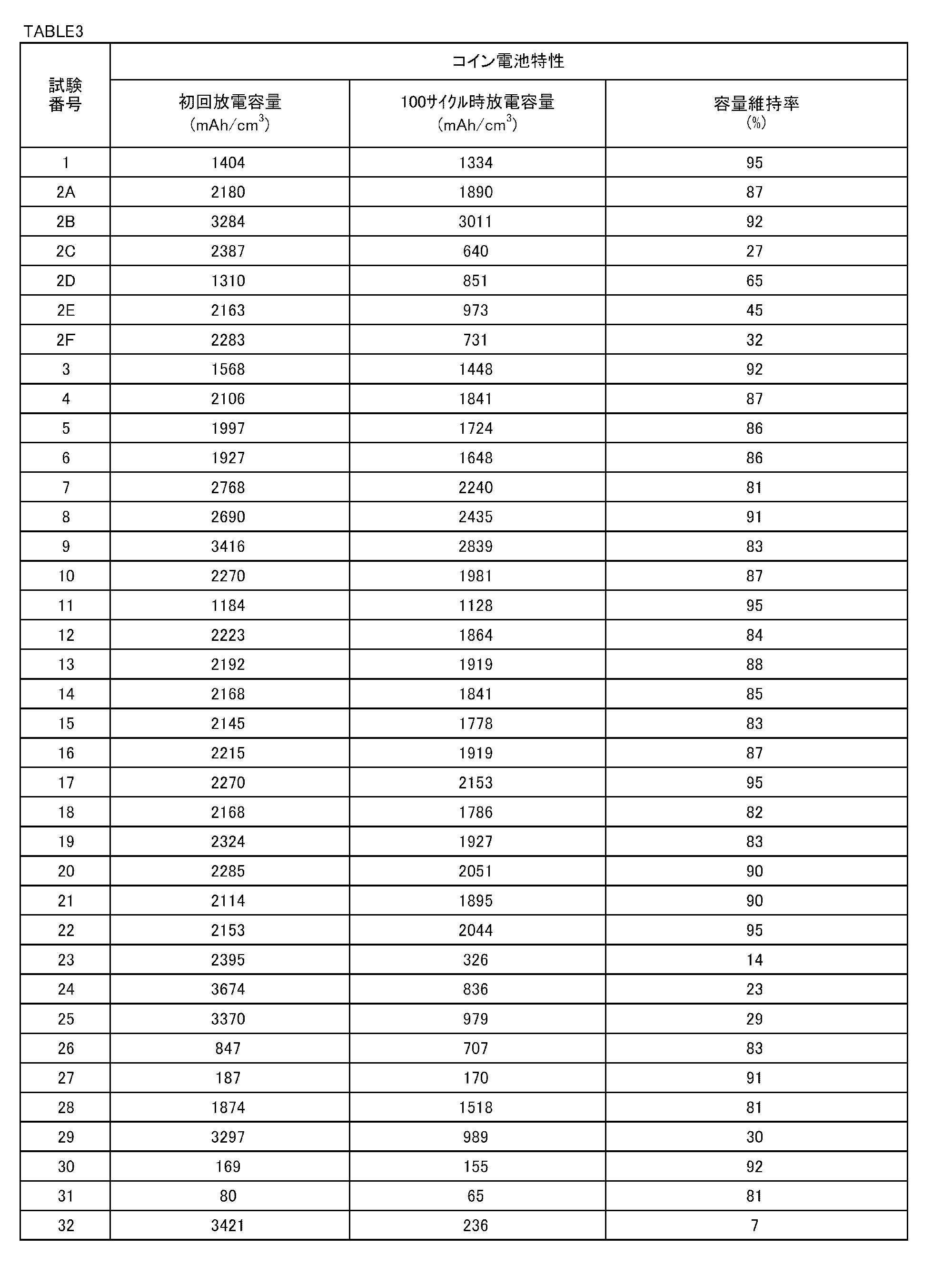
表1~表3を参照して、試験番号1、2A、2B、2D、3~22、及び28の金属粒子の化学組成は適切であり、η’相、ε相及びSn相のうち少なくとも一種の相を含んだ。なお、いずれの試験番号においても、未同定の他相の生成も認められた。さらに、ミクロ組織中の島状領域10の平均サイズは900nm以下であった。その結果、放電容量は、初回及び100サイクル後のいずれもおいても、黒鉛の理論容量(833mAh/cm3)よりも高かった。さらに、容量維持率はいずれも50%以上であった。
Claims (6)
- at%で、
Sn:10.0~22.5%、及び、
Si:10.5~23.0%を含有し、残部はCu及び不純物からなる化学組成を有する合金を含み、
前記合金は、
Cu-Snの2元系状態図において、
η’相、ε相、及びSn相のうちの少なくとも1種以上の相を有し、
前記合金のミクロ組織は、
網状領域、及び、前記網状領域に囲まれる島状領域を有し、
前記島状領域の平均サイズが、円相当径で、900nm以下である、負極活物質材料。 - 請求項1に記載の負極活物質材料であって、
前記化学組成は、Cuの一部に代えてさらに、
Ti、V、Cr、Mn、Fe、Co、Ni、Zn、Al、B及びCからなる群から選択される1種又は2種以上を含有する、負極活物質材料。 - 請求項2に記載の負極活物質材料であって、
前記化学組成は、
Ti:2.0%以下、
V:2.0%以下、
Cr:2.0%以下、
Mn:2.0%以下、
Fe:2.0%以下、
Co:2.0%以下、
Ni:3.0%以下、
Zn:3.0%以下、
Al:3.0%以下、
B:2.0%以下、及び、
C:2.0%以下からなる群から選択される1種又は2種以上を含有する、負極活物質材料。 - 請求項1~請求項3のいずれか1項に記載の負極活物質材料であって、
前記合金は、平均粒子径が、メジアン径で、0.1~45μmの合金粒子である、負極活物質材料。 - 請求項1~請求項4のいずれか1項に記載の負極活物質材料を含有する負極。
- 請求項5に記載の負極を備える電池。
Priority Applications (4)
| Application Number | Priority Date | Filing Date | Title |
|---|---|---|---|
| JP2018521738A JP6627974B2 (ja) | 2016-06-10 | 2017-06-06 | 負極活物質材料、負極及び電池 |
| CN201780035286.9A CN109312426A (zh) | 2016-06-10 | 2017-06-06 | 负极活性物质材料、负极及电池 |
| US16/305,628 US20200266430A1 (en) | 2016-06-10 | 2017-06-06 | Negative electrode active material, negative electrode, and battery |
| KR1020197000453A KR20190012263A (ko) | 2016-06-10 | 2017-06-06 | 음극 활물질 재료, 음극 및 전지 |
Applications Claiming Priority (2)
| Application Number | Priority Date | Filing Date | Title |
|---|---|---|---|
| JP2016-116003 | 2016-06-10 | ||
| JP2016116003 | 2016-06-10 |
Publications (1)
| Publication Number | Publication Date |
|---|---|
| WO2017213147A1 true WO2017213147A1 (ja) | 2017-12-14 |
Family
ID=60577803
Family Applications (1)
| Application Number | Title | Priority Date | Filing Date |
|---|---|---|---|
| PCT/JP2017/021013 Ceased WO2017213147A1 (ja) | 2016-06-10 | 2017-06-06 | 負極活物質材料、負極及び電池 |
Country Status (5)
| Country | Link |
|---|---|
| US (1) | US20200266430A1 (ja) |
| JP (1) | JP6627974B2 (ja) |
| KR (1) | KR20190012263A (ja) |
| CN (1) | CN109312426A (ja) |
| WO (1) | WO2017213147A1 (ja) |
Families Citing this family (1)
| Publication number | Priority date | Publication date | Assignee | Title |
|---|---|---|---|---|
| KR102262380B1 (ko) * | 2017-07-18 | 2021-06-08 | 닛폰세이테츠 가부시키가이샤 | 음극 활물질 재료, 음극 및 전지 |
Citations (5)
| Publication number | Priority date | Publication date | Assignee | Title |
|---|---|---|---|---|
| JPH02503071A (ja) * | 1988-02-05 | 1990-09-27 | レイノルズ・メタルズ・カンパニー | 金属ストリツプの直接鋳造装置及びその方法 |
| WO2003079469A1 (en) * | 2002-03-20 | 2003-09-25 | Matsushita Electric Industrial Co., Ltd. | Cathode material and non-aqueous electrolyte secondary battery using it |
| WO2007015508A1 (ja) * | 2005-08-02 | 2007-02-08 | Showa Denko K.K. | リチウム二次電池負極用合金 |
| JP2015159081A (ja) * | 2014-02-25 | 2015-09-03 | 新日鐵住金株式会社 | 負極活物質材料 |
| WO2015129270A1 (ja) * | 2014-02-25 | 2015-09-03 | 新日鐵住金株式会社 | 負極活物質材料、負極及び電池 |
Family Cites Families (5)
| Publication number | Priority date | Publication date | Assignee | Title |
|---|---|---|---|---|
| MY181261A (en) * | 2012-08-27 | 2020-12-21 | Nippon Steel Corp | Negative electrode active material |
| HUE044657T2 (hu) * | 2014-02-25 | 2019-11-28 | Nippon Steel & Sumitomo Metal Corp | Negatív elektródaktív anyag, negatív elektróda és cella |
| JP2016025060A (ja) * | 2014-07-24 | 2016-02-08 | トヨタ自動車株式会社 | リチウムイオン二次電池用電極シートの製造方法 |
| JP6736868B2 (ja) * | 2015-11-04 | 2020-08-05 | 日本製鉄株式会社 | 負極活物質材料、負極及び電池、並びに、負極活物質材料の製造方法 |
| US11056687B2 (en) * | 2016-05-18 | 2021-07-06 | Nippon Steel Corporation | Negative electrode active material, negative electrode, and battery |
-
2017
- 2017-06-06 CN CN201780035286.9A patent/CN109312426A/zh active Pending
- 2017-06-06 US US16/305,628 patent/US20200266430A1/en not_active Abandoned
- 2017-06-06 WO PCT/JP2017/021013 patent/WO2017213147A1/ja not_active Ceased
- 2017-06-06 KR KR1020197000453A patent/KR20190012263A/ko not_active Ceased
- 2017-06-06 JP JP2018521738A patent/JP6627974B2/ja active Active
Patent Citations (5)
| Publication number | Priority date | Publication date | Assignee | Title |
|---|---|---|---|---|
| JPH02503071A (ja) * | 1988-02-05 | 1990-09-27 | レイノルズ・メタルズ・カンパニー | 金属ストリツプの直接鋳造装置及びその方法 |
| WO2003079469A1 (en) * | 2002-03-20 | 2003-09-25 | Matsushita Electric Industrial Co., Ltd. | Cathode material and non-aqueous electrolyte secondary battery using it |
| WO2007015508A1 (ja) * | 2005-08-02 | 2007-02-08 | Showa Denko K.K. | リチウム二次電池負極用合金 |
| JP2015159081A (ja) * | 2014-02-25 | 2015-09-03 | 新日鐵住金株式会社 | 負極活物質材料 |
| WO2015129270A1 (ja) * | 2014-02-25 | 2015-09-03 | 新日鐵住金株式会社 | 負極活物質材料、負極及び電池 |
Also Published As
| Publication number | Publication date |
|---|---|
| KR20190012263A (ko) | 2019-02-08 |
| US20200266430A1 (en) | 2020-08-20 |
| CN109312426A (zh) | 2019-02-05 |
| JP6627974B2 (ja) | 2020-01-08 |
| JPWO2017213147A1 (ja) | 2019-04-18 |
Similar Documents
| Publication | Publication Date | Title |
|---|---|---|
| JP3562398B2 (ja) | 非水電解質二次電池用負極材料の製造方法と二次電池 | |
| JPWO2015064633A1 (ja) | 負極活物質及びその製造方法並びにそれを用いた負極及び非水電解質二次電池 | |
| JP2011034836A (ja) | ナノサイズ粒子、ナノサイズ粒子を含むリチウムイオン二次電池用負極材料、リチウムイオン二次電池用負極、リチウムイオン二次電池、ナノサイズ粒子の製造方法 | |
| JP6515363B1 (ja) | 負極活物質材料、負極及び電池 | |
| MX2015002323A (es) | Material activo de electrodo negativo. | |
| JP6777144B2 (ja) | 負極活物質材料、負極及び電池 | |
| JP2018200876A (ja) | 負極活物質材料、負極及び電池 | |
| JP6711475B1 (ja) | 複合粒子群、負極活物質粒子群、負極、電池、及び、複合粒子群に含有される凸部露出複合粒子 | |
| JPWO2019031601A1 (ja) | Si系負極活物質 | |
| JP6627974B2 (ja) | 負極活物質材料、負極及び電池 | |
| WO2015129267A1 (ja) | 負極活物質材料、負極及び電池 | |
| JP6187706B2 (ja) | 負極活物質材料、負極及び電池 | |
| KR102667548B1 (ko) | 음극 활물질 재료, 음극 및 전지 | |
| JP6747331B2 (ja) | 負極活物質材料、負極及び電池 | |
| JP2022161719A (ja) | 負極活物質粒子、負極、及び、電池 | |
| WO2016059793A1 (ja) | 負極活物質材料、負極、電池、及び、負極活物質材料の製造方法 | |
| JP2016081768A (ja) | 電極活物質材料、電極及び電池 |
Legal Events
| Date | Code | Title | Description |
|---|---|---|---|
| 121 | Ep: the epo has been informed by wipo that ep was designated in this application |
Ref document number: 17810322 Country of ref document: EP Kind code of ref document: A1 |
|
| ENP | Entry into the national phase |
Ref document number: 2018521738 Country of ref document: JP Kind code of ref document: A |
|
| NENP | Non-entry into the national phase |
Ref country code: DE |
|
| ENP | Entry into the national phase |
Ref document number: 20197000453 Country of ref document: KR Kind code of ref document: A |
|
| 122 | Ep: pct application non-entry in european phase |
Ref document number: 17810322 Country of ref document: EP Kind code of ref document: A1 |