WO2017212698A1 - 発音装置 - Google Patents
発音装置 Download PDFInfo
- Publication number
- WO2017212698A1 WO2017212698A1 PCT/JP2017/007336 JP2017007336W WO2017212698A1 WO 2017212698 A1 WO2017212698 A1 WO 2017212698A1 JP 2017007336 W JP2017007336 W JP 2017007336W WO 2017212698 A1 WO2017212698 A1 WO 2017212698A1
- Authority
- WO
- WIPO (PCT)
- Prior art keywords
- case
- opening
- frame
- sound
- space
- Prior art date
- Legal status (The legal status is an assumption and is not a legal conclusion. Google has not performed a legal analysis and makes no representation as to the accuracy of the status listed.)
- Ceased
Links
Images
Classifications
-
- H—ELECTRICITY
- H04—ELECTRIC COMMUNICATION TECHNIQUE
- H04R—LOUDSPEAKERS, MICROPHONES, GRAMOPHONE PICK-UPS OR LIKE ACOUSTIC ELECTROMECHANICAL TRANSDUCERS; ELECTRIC HEARING AIDS; PUBLIC ADDRESS SYSTEMS
- H04R1/00—Details of transducers, loudspeakers or microphones
- H04R1/20—Arrangements for obtaining desired frequency or directional characteristics
- H04R1/22—Arrangements for obtaining desired frequency or directional characteristics for obtaining desired frequency characteristic only
- H04R1/28—Transducer mountings or enclosures modified by provision of mechanical or acoustic impedances, e.g. resonator, damping means
-
- H—ELECTRICITY
- H04—ELECTRIC COMMUNICATION TECHNIQUE
- H04R—LOUDSPEAKERS, MICROPHONES, GRAMOPHONE PICK-UPS OR LIKE ACOUSTIC ELECTROMECHANICAL TRANSDUCERS; ELECTRIC HEARING AIDS; PUBLIC ADDRESS SYSTEMS
- H04R11/00—Transducers of moving-armature or moving-core type
- H04R11/02—Loudspeakers
Definitions
- the present invention relates to a sound producing device in which the inside of a case is divided into two spaces by a vibrating body and generates sound by the vibration of the vibrating body.
- Patent Document 1 describes an invention relating to an electroacoustic transducer.
- a diaphragm is bonded to a resin film, and an outer peripheral portion of the resin film is bonded to the upper surface of the diaphragm frame.
- the housing is divided into two, the outer peripheral part of the diaphragm frame is sandwiched between the open ends of the two housings, and the diaphragm frame and the two housings are fixed by laser welding.
- the armature part is provided in the housing.
- the armature unit includes a magnet and a coil, and an armature that is vibrated by a current applied to the coil, and the diaphragm is vibrated by the vibration of the armature.
- the interior of the housing is divided into two spaces by a diaphragm and a resin film, and air vibrations in one space caused by diaphragm vibrations are transmitted from the notches formed in the housing to the external space and sounded.
- the electroacoustic transducer described in Patent Document 1 has a vent hole formed in a resin film in order to adjust a difference in atmospheric pressure between two spaces in a housing.
- pressure acts on the resin film around the vent hole by the air that tries to pass through the vent hole. Due to this change in pressure, the resin film may be locally deformed or vibrated, which affects the sound pressure frequency characteristics.
- it is necessary to manage the opening area and opening position of the vent hole opened in the resin film with high accuracy. Therefore, the work of processing the vent hole becomes complicated.
- the present invention solves the above-mentioned conventional problems, makes it possible to adjust the pressure difference between the two spaces in the case without opening a vent hole in the resin film, and facilitates the processing work, and the sound pressure.
- An object of the present invention is to provide a sound generating device that can reduce variation in frequency characteristics.
- a vibrating body supported by a frame and a drive mechanism for driving the vibrating body are housed in the case, and the inside of the case is divided into a sound generation space and an adjacent space by the vibrating body.
- the case has a sounding opening communicating with the sounding space, and at least one of the case and the frame has a vent hole that opens in the same direction as the sounding opening through the adjacent space. It is characterized by this.
- the opening area of the vent hole is smaller than the opening area of the sound producing port.
- the sound generating nozzle is fixed to the case, and the sound generating port and the vent hole are opened in the sound generating passage of the sound generating nozzle.
- the frame is sandwiched between two cases, and the opening end of the case and the frame are joined to at least one of the opening end of the case and the frame. It can be configured as a groove in which a vent hole is formed.
- the frame has an opening located in the case, and the vibrating body is disposed in the opening. It is preferable that the groove is formed in the frame, and the groove is continuous with the opening.
- the vent hole may be formed through the side wall portion of the case.
- the sounding device of the present invention can correct the pressure difference between the two spaces in the case without forming a hole in the resin film constituting the vibrating body.
- a ventilation hole for adjusting the pressure difference in at least one of the case and the frame, the opening area and opening position of the ventilation hole can be determined with high accuracy. It becomes possible to suppress the occurrence of variations.
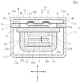
- FIG. 3 is a cross-sectional view of the sounding device shown in FIG.
- the top view which shows the state with which the diaphragm, the upper yoke, and the armature were attached to the flame
- FIG. 3 is a cross-sectional view taken along line VV shown in FIG.
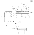
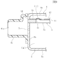
- the expanded sectional view which expands and shows the opening part of the sound-emitting opening and ventilation hole of the sound-producing device of 1st Embodiment shown in FIG.
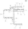
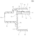
- the expanded sectional view which expands and shows the opening part of the sound-emitting opening and ventilation hole of the sound-producing device of the 2nd Embodiment of this invention The expanded sectional view which expands and shows the opening part of the sound-emitting opening and ventilation hole of the sound-producing device of the 3rd Embodiment of this invention, The expanded sectional view which expands and shows the opening part of the sound-emitting opening and ventilation hole of the sound-producing device of the 4th Embodiment of this invention,
- the sounding device 1 has a case 2.
- Case 2 includes a lower case 3 and an upper case 4.
- the lower case 3 and the upper case 4 are formed by die casting using a nonmagnetic material or a magnetic metal material, or are formed by pressing from a nonmagnetic or magnetic metal plate.
- the lower case 3 has a bottom 3a, a side wall 3b surrounding the four side surfaces, and an open end 3c at the upper end of the side wall 3b.
- the upper case 4 has a ceiling part 4a, a side wall part 4b surrounding the four side surfaces, and an open end part 4c at the lower end of the side wall part.
- the internal space of the lower case 3 is wider than the internal space of the upper case 4, and the upper case 4 functions as a lid for the lower case.
- the frame 5 is sandwiched between the opening end 3 c of the lower case 3 and the opening end 4 c of the upper case 4.
- the frame 5 is formed of a nonmagnetic material or a metal plate of a magnetic material having a uniform thickness dimension in the Z direction.
- An opening 5c is formed in the center of the frame 5 so as to penetrate vertically.
- the opening 5c is a rectangular hole.
- the frame 5 is a rectangular frame, and a peripheral portion of the opening 5c on the upper surface in the drawing is a vibrating body mounting surface 5b, and a peripheral portion of the opening 5c on the lower surface in the drawing is a driving mechanism mounting surface 5a.
- a vibrating body 10 is attached to the upper side of the frame 5 in the drawing.
- the vibrating body 10 includes a diaphragm 11 and a vibration support sheet 12.
- the diaphragm 11 is made of a thin metal material such as aluminum or SUS304, and ribs for enhancing the bending strength are press-molded as necessary.
- the vibration support sheet 12 is more easily bent and deformed than the vibration plate 11, and is formed of a resin sheet (resin film) such as PET (polyethylene terephthalate), nylon, or polyurethane.
- the diaphragm 11 and the vibration support sheet 12 are rectangular and rectangular.
- the area of the diaphragm 11 is smaller than the opening area of the opening 5 c of the frame 5, and the area of the vibration support sheet 12 is larger than that of the diaphragm 11.
- the diaphragm 11 is fixed to the lower surface of the vibration support sheet 12 by using an adhesive.
- the outer peripheral edge 12a of the vibration support sheet 12 protrudes to the periphery from the outer peripheral edge of the diaphragm 11, and the outer peripheral edge 12a is attached to the vibrating body mounting surface 5b which is the frame-shaped upper surface of the frame 5 with an adhesive. Is fixed.
- the vibration plate 11 can vibrate so that the free end 11b is displaced in the Z direction by using the fulcrum side end portion 11c as a fulcrum by the bending and elasticity of the vibration support sheet 12.
- the magnetic field generation unit 20 is attached to the drive mechanism attachment surface 5a of the frame 5.
- the magnetic field generation unit 20 has an upper yoke 21 and a lower yoke 22.
- the upper yoke 21 and the lower yoke 22 are made of a magnetic material, and are made of, for example, a steel plate such as a cold rolled steel plate represented by SPCC, a Ni—Fe alloy, or the like.
- the lower yoke 22 is bent into a U shape to form a bottom surface portion 22a and a pair of side surface portions 22b and 22b bent upward on both sides in the X direction.
- the upper end portions of the side surface portions 22b and 22b are joined to the inner surface 21a of the flat plate-shaped upper yoke 21, and the upper yoke 21 and the lower yoke 22 are fixed by laser spot welding or the like.
- the inner surface of the bottom surface portion 22a of the lower yoke 22 and the inner surface 21a of the upper yoke 21 face each other in parallel.
- the first magnet 24 is fixed to the inner surface 21 a of the upper yoke 21, and the second magnet 25 is attached to the inner surface of the bottom surface portion 22 a of the lower yoke 22. Is fixed.
- the magnets 24 and 25 are magnetized so that the magnetized surface 24a of the first magnet 24 and the magnetized surface 25a of the second magnet 25 have opposite polarities.
- a gap ⁇ is set in the Z direction between the magnetized surface 24 a of the first magnet 24 and the magnetized surface 25 a of the second magnet 25.
- a coil 27 is provided at a position aligned with the magnetic field generation unit 20.
- the coil 27 is wound so that the conducting wire circulates around a winding axis extending in the Y direction.
- the end surface of the coil 27 facing the left side in the Y direction is a joint surface 27a, and this joint surface 27a is the side surface of the upper yoke 21 and the lower yoke 22 of the magnetic field generating unit 20 facing the Y direction. It is fixed with adhesive.
- the winding center line of the coil 27 is positioned and fixed so as to coincide with the center of the interval ⁇ between the first magnet 24 and the second magnet 25.
- the sound generator 1 is provided with an armature 32.
- the armature 32 is formed of a magnetic material plate having a uniform thickness, and is formed of, for example, a Ni—Fe alloy.
- the armature 32 is pressed and formed into a U shape having a movable portion 32a, a fixed portion 32b, and a bent portion 32c.
- a tip portion 32d facing the free end of the movable portion 32a of the armature 32 has a small width dimension in the X direction, and a connecting hole 32e is formed in the tip portion 32d so as to penetrate vertically. Yes.
- the fixing portion 32b of the armature 32 is fixed to a joint surface 21b which is an upward outer surface of the upper yoke 21.
- the movable portion 32 a of the armature 32 is inserted into the space 27 c of the coil 27, and further inserted into the interval ⁇ between the first magnet 24 and the second magnet 25.
- the tip 32d of the armature 32 protrudes to the left side in the drawing with respect to the interval ⁇ .
- the joint surface 21 b on the upper surface of the upper yoke 21 is joined and fixed to the drive mechanism mounting surface 5 a on the lower surface of the frame 5.
- the upper yoke 21 is installed so as to cross the opening 5 c of the frame 5 in the X direction, and both ends of the upper yoke 21 in the X direction are the drive mechanism mounting surfaces of the frame 5.
- the upper yoke 21 and the frame 5 are fixed to each other by laser spot welding.
- the fixing portion 32 b of the armature 32 is smaller than the opening area of the opening 5 c of the frame 5, and the drive mechanism mounting surface 5 a in which the joint surface 21 b on the upper surface of the upper yoke 21 is the lower surface of the frame 5.
- the fixing portion 32b of the armature 32 fixed to the joint surface 21b enters the inside of the opening 5c of the frame 5 as shown in FIGS.
- the thickness dimension of the fixing portion 32b in the Z direction is smaller than the thickness dimension of the frame 5 in the Z direction, and vibration is generated between the vibration plate 11 located in the opening 5c and the fixing portion 32b of the armature 32.
- a gap in the Z direction is provided so that the plate 11 can vibrate in the Z direction.
- the transmission body 33 is a needle-like member made of metal or synthetic resin, and is made of, for example, a pin material of SUS202.
- the upper end 33a of the transmission body 33 is inserted into a mounting hole 11e formed in the diaphragm 11, and the diaphragm 11 and the transmission body 33 are fixed by an adhesive or soldering.
- the lower end portion 33b of the transmission body 33 is inserted into a connecting hole 32e formed in the tip portion 32d of the armature 32, and the transmission body 33 and the tip portion 32d are fixed by laser spot welding, adhesive or soldering. .
- the transmission body 33 traverses the opening 5c of the frame 5 up and down, and a part of the transmission body 33 is located inside the opening 5c.
- the magnetic field generation unit 20, the armature 32, and the transmission body 33 constitute a drive mechanism for operating the vibrating body 10.
- the vibration support sheet 12 is adhered to a range of a certain width dimension W from the opening edge of the opening 5 c on the vibration body mounting surface 5 b that is the upper surface of the frame 5.
- the outer peripheral portion is a sandwiched portion 6 that does not have the vibration support sheet 12 and the adhesive layer that bonds the vibration support sheet 12.
- the opening end 3 c of the lower case 3 is abutted against the lower surface of the sandwiched portion 6, and the opening end 4 c of the upper case 4 is abutted against the upper surface of the sandwiched portion 6.
- the lower case 3 and the upper case 4 and the sandwiched portion 6 are fixed by racer spot welding.
- the space inside the case 2 is divided vertically by the diaphragm 11 and the vibration support sheet 12.
- a space above the diaphragm 11 and the vibration support sheet 12 constituting the vibrating body 10 and inside the upper case 4 is a sound generation space (i).
- the sound generation space (i) communicates with the external space through a sound generation port 4d formed in the side wall 4b of the upper case 4.
- the sound generation opening 4 d is formed by cutting out a part of the side wall portion 4 b at the joint portion between the sandwiched portion 6 of the frame 5 and the opening end portion 4 c of the upper case 4.
- the space below the diaphragm 11 and the vibration support sheet 12 constituting the vibrating body 10 and inside the lower case 3 is the adjacent space (ii).
- a ventilation hole 7 is formed in a joint portion between the sandwiched portion 6 of the frame 5 and the opening end portion 3 c of the lower case 3.
- the adjacent space (ii) communicates with the outside through the vent hole 7.
- the sound generation opening 4d and the ventilation hole 7 are opened in the same direction on the same side surface of the case 2, and the sound generation opening 4d and the ventilation hole 7 are opened in the same direction.
- the sound generation nozzle 41 is fixed to the side surface of the case 2. Both the sound generating port 4d and the vent hole 7 communicate with the sound generating passage 41a of the sound generating nozzle 41.
- a groove 7a in which a part of the side wall 3b is cut out is formed in the opening end 3c of the lower case 3.
- a groove 7b is formed in the drive mechanism mounting surface 5a, which is the lower surface of the frame 5.
- the groove 7b is formed continuously from the outer end of the frame 5 to the opening 5c. That is, the groove 7 b is continuously formed so as to cross the frame portion of the frame 5. Then, the groove 7 a of the lower case 3 and the groove 7 b of the frame 5 are combined to form a vent hole 7.
- an intake / exhaust port 3d is formed at the bottom of the lower case 3.
- the adjacent space (ii) on the lower side 3 with respect to the diaphragm 11 and the vibration support sheet 12 communicates with the outside air through the intake / exhaust port 3d. Since the adjacent space (ii) communicates with the outside air through the vent hole 7, the lower case 3 does not have to be provided with the intake / exhaust port 3d.
- a pair of wiring holes 3 e are opened in the side wall portion 3 b of the lower case 3, and as shown in FIG. 3, the pair of terminal portions 27 b of the conductive wires constituting the coil 27 are respectively connected to the wiring holes. It is pulled out from 3e.
- the substrate 42 is fixed to the outside of the side wall portion 3b of the case, and the terminal portion 27b passes through a small hole formed in the substrate 42 so that the small hole is closed, whereby the wiring hole 3e is closed from the outside.
- each part is assembled into the frame 5.
- the diaphragm 11 and the vibration support sheet 12 are joined to the opening 5 c of the frame 5.
- the magnetic field generating unit 20 is assembled by joining the first magnet 24 to the inner surface 21a of the upper yoke 21 and joining the second magnet 25 to the upper surface of the bottom surface portion 22a of the lower yoke 22.
- the yoke 22 is fixed by racer spot welding or the like.
- the joint surface 27a of the coil 27 is fixed to the side surfaces of the upper yoke 21 and the lower yoke 22 facing the Y direction with an adhesive.
- the armature 32 is pressed and the bent portion 32c is processed so that the movable portion 32a and the fixed portion 32b can face each other in the Z direction in parallel.
- the movable portion 32a of the armature 32 is inserted into the space 27c at the winding center of the coil 27 and the interval ⁇ between the first magnet 24 and the second magnet 25, and the fixed portion 32b is joined to the upper surface of the upper yoke 21. It abuts on the surface 21b and is fixed by laser spot welding or the like.
- the partial assembly in which the coil 27 and the armature 32 are incorporated in the magnetic field generating unit 20 including the yokes 21 and 22 and the magnets 24 and 25 is fixed to the drive mechanism mounting surface 5a of the frame 5.
- the joint surface 21b of the upper yoke 21 is abutted against the drive mechanism mounting surface 5a of the frame 5 and fixed by laser welding or the like.
- the coil 27, and the armature 32 are assembled on the drive mechanism mounting surface 5a, the tip 32d of the movable portion 32a of the armature 32 and the diaphragm 11 are connected by the transmission body 33 to assemble the drive mechanism. To complete.
- the sandwiched portion 6 on the periphery of the frame 5 is sandwiched between the open end 3c of the lower case 3 and the open end 4c of the upper case 4, and the lower case 3, the frame 5, and the upper case 4 are lasered. Fix with spot welding.
- the terminal portion 27 b of the conductive wire of the coil 27 is drawn out from the wiring hole 3 e of the lower case 3 and the wiring hole 3 e is covered with the substrate 42. Further, the sound generating nozzle 41 is fixed to the case 2 to complete the assembly.
- the diaphragm 11 vibrates inside the case 2
- sound pressure having a phase difference of 180 degrees is generated between the sound generation space (i) and the adjacent space (ii), but compared with the opening area of the sound generation opening 4d.
- the opening area of the vent hole 7 is sufficiently small, it is possible to limit interference of sound pressures having different phases inside the sound generation passage 41a of the sound generation nozzle 41.
- the ratio of the opening area of the sound generation passage 41a / the opening area of the sound generation opening 4a is preferably 1/5 or less, and more preferably 1/10 or less.
- the vent hole 7 for eliminating the pressure difference between the sound producing space (i) and the adjacent space (ii) can be processed with its opening area and opening position set with high accuracy. Therefore, it is possible to prevent the variation in the opening area and the opening position, and to suppress the variation in the sound pressure frequency characteristics from product to product.
- vent hole 7 formed in the case 2 can be formed by processing the groove 7 a in the lower case 3 and processing the groove 7 b in the drive mechanism mounting surface 5 a of the frame 5.
- the groove 7a may be processed so as to cross the side wall 3b at the opening end 4c of the lower case 3, and the groove 7b may be processed so as to be continuous with the opening 5c on the drive mechanism mounting surface 5a of the frame 5. Since it is good, the process of the ventilation path 7 is also easy.
- vent hole 7 may be formed only by the groove 7b processed in the frame 5, or as in the third embodiment shown in FIG.
- the vent hole 7 may be formed only by the groove 7 a processed in the case 3.
- a through hole 7c that penetrates the side wall 3b of the lower case 3 may be used as a vent hole.
Landscapes
- Physics & Mathematics (AREA)
- Engineering & Computer Science (AREA)
- Acoustics & Sound (AREA)
- Signal Processing (AREA)
- Electromagnetism (AREA)
- Health & Medical Sciences (AREA)
- Otolaryngology (AREA)
- Electrostatic, Electromagnetic, Magneto- Strictive, And Variable-Resistance Transducers (AREA)
Abstract
【課題】 ケース内で振動板を挟んで区分された発音空間と隣接空間との気圧差を高精度に解消できる発音装置を提供する。 【解決手段】 フレーム5の振動体取付け面5bに振動体10を構成する振動板11と振動支持シート12とが設置されている。振動板11よりも上の発音空間(i)は発音口4dを経て発音ノズル41の発音通路41aに通じ、振動板11よりも下側の隣接空間(ii)は通気穴7を通じて発音通路41aに通じている。そのため、発音通路41a内に大きな気圧変化が生じても、発音空間(i)と隣接空間(ii)との間に大きな気圧差が発生するのを防止できる。
Description
本発明は、ケースの内部が振動体によって2つの空間に区分され、前記振動体の振動によって発音する発音装置に関する。
特許文献1に、電気音響変換器に関する発明が記載されている。
この電気音響変換器は、樹脂フィルムにダイヤフラムが接着され、樹脂フィルムの外周部分がダイヤフラムフレームの上面に接着されている。ハウジングは2つに分離されており、ダイヤフラムフレームの外周部分が2つのハウジングの開口端部に挟まれ、ダイヤフラムフレームと2つのハウジングとがレーザー溶接で固定されている。
この電気音響変換器は、樹脂フィルムにダイヤフラムが接着され、樹脂フィルムの外周部分がダイヤフラムフレームの上面に接着されている。ハウジングは2つに分離されており、ダイヤフラムフレームの外周部分が2つのハウジングの開口端部に挟まれ、ダイヤフラムフレームと2つのハウジングとがレーザー溶接で固定されている。
ハウジング内には、アーマチュア部が設けられている。アーマチュア部は、磁石およびコイルと、前記コイルに与えられる電流で振動させられるアーマチュアとを有しており、前記アーマチュアの振動によって前記ダイヤフラムが振動させられる。ハウジングの内部はダイヤフラムと樹脂フィルムによって2つの空間に区分され、ダイヤフラムの振動によって生じる一方の空間の空気振動が、ハウジングに形成された切欠き部から外部空間に伝達されて発音する。
この電気音響変換器では、外気圧が変化したときに、ダイヤフラムと樹脂フィルムで区分されたハウジング内の2つの空間の気圧差を調整して、ダイヤフラムが常に適正な周波数特性で動作できるようにする必要がある。そのため、特許文献1に記載されたものでは、ダイヤフラムに形成された穴部の内部に位置する樹脂フィルムにベント穴を形成し、ベント穴で2つの空間を連通させている。
特許文献1に記載の電気音響変換器は、ハウジング内の2つの空間の気圧差を調整するために、樹脂フィルムにベント穴を形成している。しかし、樹脂フィルムにベント穴を形成すると、ベント穴を通過しようとする空気によってベント穴の周囲において樹脂フィルムに圧力が作用する。この圧力の変化により、樹脂フィルムが局部的に変形したり振動するおそれがあり、音圧周波数特性に影響を与えることになる。この影響を少なくするためには、樹脂フィルムに開口するベント穴の開口面積や開口位置を高精度に管理することが必要になる。そのため、ベント穴の加工作業が煩雑になる。また、樹脂フィルムではベント穴の径の管理などが難しく、歩留まりも悪化する原因となる。
本発明は上記従来の課題を解決するものであり、樹脂フィルムにベント穴を開口せずに、ケース内の2つの空間の気圧差を調整できるようにして、加工作業を容易にし、また音圧周波数特性のばらつきを少なくすることができる発音装置を提供することを目的としている。
本発明は、ケースの内部に、フレームに支持された振動体と、前記振動体を駆動する駆動機構とが収納され、前記ケースの内部が、前記振動体によって発音空間と、隣接空間とに区分されている発音装置において、
前記ケースには、前記発音空間と連通する発音口が開口し、前記ケースと前記フレームの少なくとも一方には、前記隣接空間と通じて前記発音口と同じ向きに開口する通気穴が形成されていることを特徴とするものである。
前記ケースには、前記発音空間と連通する発音口が開口し、前記ケースと前記フレームの少なくとも一方には、前記隣接空間と通じて前記発音口と同じ向きに開口する通気穴が形成されていることを特徴とするものである。
本発明の発音装置では、前記通気穴の開口面積が、前記発音口の開口面積よりも小さい。
本発明の発音装置は、前記ケースに発音ノズルが固定されており、前記発音口と前記通気穴が、前記発音ノズルの発音通路内に開口しているものである。
本発明の発音装置は、前記フレームが、2つのケースに挟まれており、前記ケースの開口端部と前記フレームとの接合部において、前記ケースの前記開口端部と前記フレームの少なくとも一方に前記通気穴を構成する溝が形成されているものとして構成できる。
この場合に、前記フレームは、ケース内に位置する開口部を有し、前記振動体が前記開口部に配置されており、
前記溝が前記フレームに形成され、前記溝が前記開口部に連続していることが好ましい。
前記溝が前記フレームに形成され、前記溝が前記開口部に連続していることが好ましい。
本発明の発音装置は、前記通気穴は、前記ケースの側壁部を貫通して形成されているものであってもよい。
本発明の発音装置は、振動体を構成する樹脂フィルムに穴を形成することなく、ケース内の2つの空間の気圧差を修正できるようになる。気圧差を調整するための通気穴を、ケースとフレームの少なくとも一方に形成することで、通気穴の開口面積と開口位置を高精度に決めることができ、通気穴の存在によって音圧周波数特性にばらつきなどが生じるのを抑制できるようになる。
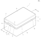
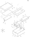
図1と図2などに示すように、本発明の第1の実施の形態の発音装置1は、ケース2を有している。ケース2は下ケース3と上ケース4とから構成されている。下ケース3と上ケース4は非磁性材料または磁性の金属材料を使用しダイキャスト法で形成され、あるいは、非磁性または磁性金属板からプレス加工されて形成されている。
図2に示すように、下ケース3は、底部3aと、4側面を囲む側壁部3bと、側壁部3bの上端の開口端部3cを有している。上ケース4は天井部4aと、4側面を囲む側壁部4bと、側壁部の下端の開口端部4cを有している。下ケース3の内部空間は、上ケース4の内部空間よりも広く、上ケース4は下ケースの蓋体として機能している。
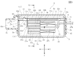
図3と図5に示すように、下ケース3の開口端部3cと上ケース4の開口端部4cとの間にフレーム5が挟まれている。図2に示すように、フレーム5は、Z方向の厚さ寸法が均一な非磁性材料または磁性材料の金属板材で形成されている。フレーム5の中央部に、開口部5cが上下に貫通して形成されている。開口部5cは矩形状の穴である。
フレーム5は、矩形状の枠体であり、図示上面の前記開口部5cの周辺部分が振動体取付け面5bで、図示下面の開口部5cの周囲部分が駆動機構取付け面5aである。
図2と図5に示すように、フレーム5の図示上側に振動体10が取り付けられている。振動体10は、振動板11と振動支持シート12とで構成されている。振動板11はアルミニウムやSUS304などの薄い金属材料で形成されており、必要に応じて曲げ強度を増強するためのリブがプレス成形されている。振動支持シート12は振動板11よりも撓み変形しやすいものであり、例えばPET(ポリエチレンテレフタレート)やナイロンあるいはポリウレタンなどの樹脂シート(樹脂フィルム)で形成されている。
振動板11と振動支持シート12は矩形状であり長方形である。振動板11の面積は、フレーム5の開口部5cの開口面積よりも小さく、振動支持シート12の面積は振動板11よりも大きい。図3と図5に示すように、振動板11は振動支持シート12の下面に接着剤を用いて接着されて固定されている。振動支持シート12の外周縁部12aは振動板11の外周縁よりも周囲に突出しており、この外周縁部12aが、フレーム5の枠形状の上面である振動体取付け面5bに接着剤を介して固定されている。振動板11は、振動支持シート12の撓みと弾性によって、支点側端部11cを支点として、自由端11bがZ方向へ変位するように振動可能である。
図3と図4に示すように、フレーム5の駆動機構取付け面5aに磁界発生ユニット20が取り付けられている。図2に示すように、磁界発生ユニット20は、上部ヨーク21と下部ヨーク22とを有している。上部ヨーク21と下部ヨーク22は、磁性材料で形成されており、例えばSPCCに代表される冷間圧延鋼板などの鋼板やNi-Fe合金などで形成されている。
図2に示すように、下部ヨーク22はU字形状に曲げられて、底面部22aと、X方向の両側で上向きに折り曲げられた一対の側面部22b,22bとが形成されている。側面部22b,22bの上端部が、平板形状の上部ヨーク21の内面21aに接合され、レーザースポット溶接などで、上部ヨーク21と下部ヨーク22とが固定されている。上部ヨーク21と下部ヨーク22とが固定されると、下部ヨーク22の底面部22aの内面と、上部ヨーク21の内面21aとが平行に対向する。
図2と図3および図5に示すように、磁界発生ユニット20では、上部ヨーク21の内面21aに第1の磁石24が固定され、下部ヨーク22の底面部22aの内面に第2の磁石25が固定されている。第1の磁石24の着磁面24aと第2の磁石25の着磁面25aは、互いに逆の極性となるように、各磁石24,25が着磁されている。第1の磁石24の着磁面24aと第2の磁石25の着磁面25aとの間に、Z方向に間隔δが設定されている。
図2と図3に示すように、磁界発生ユニット20と並ぶ位置にコイル27が設けられている。コイル27はY方向に延びる巻き軸を中心として導線が周回するように巻かれている。図3に示すように、コイル27のY方向の左側に向く端面が接合面27aとなっており、この接合面27aが磁界発生ユニット20の上部ヨーク21と下部ヨーク22のY方向に向く側面に接着剤などで固定されている。このとき、コイル27の巻き中心線が、第1の磁石24と第2の磁石25との間隔δの中心に一致するように位置決めされて互いに固定されている。
図2と図3に示すように、発音装置1にアーマチュア32が設けられている。アーマチュア32は厚さが均一な磁性材料の板材で形成されており、例えば、Ni-Fe合金で形成されている。アーマチュア32はプレス加工されて、可動部32aと固定部32bと曲げ部32cを有するU字形状に形成されている。図2に示すように、アーマチュア32の可動部32aの自由端側に向く先部32dはX方向の幅寸法が小さくなっており、先部32dに連結穴32eが上下に貫通して形成されている。
図3と図4に示すように、アーマチュア32の固定部32bは、上部ヨーク21の上向きの外面である接合面21bに固定されている。アーマチュア32の可動部32aは、コイル27の空間27cの内部に挿入され、さらに第1の磁石24と第2の磁石25との間隔δ内に挿入されている。アーマチュア32の先部32dは、前記間隔δよりも図示左側に飛び出している。
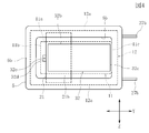
図3に示すように、上部ヨーク21の上面の接合面21bがフレーム5の下面の駆動機構取付け面5aに接合されて固定されている。図4と図5に示すように、上部ヨーク21は、フレーム5の開口部5cをX方向へ横断するように設置され、上部ヨーク21のX方向の両端部が、フレーム5の駆動機構取付け面5aに接合されて、上部ヨーク21とフレーム5がレーザースポット溶接で固定されている。
図4に示すように、アーマチュア32の固定部32bは、フレーム5の開口部5cの開口面積よりも小さく、上部ヨーク21の上面の接合面21bが、フレーム5の下面である駆動機構取付け面5aに固定されると、図3と図5に示すように、前記接合面21bに固定されているアーマチュア32の固定部32bが、フレーム5の開口部5cの内部に入り込む。固定部32bのZ方向の厚さ寸法は、フレーム5のZ方向の厚さ寸法よりも小さく、同じく開口部5c内に位置する振動板11と、アーマチュア32の固定部32bとの間に、振動板11がZ方向に振動できるようにZ方向の隙間が空けられている。
図3に示すように、振動板11の自由端11bと、アーマチュア32の先部32dは伝達体33で連結されている。伝達体33は金属または合成樹脂で形成された針状部材であり、例えばSUS202のピン材で形成されている。伝達体33の上端33aは振動板11に形成された取付け穴11eに挿入されて、振動板11と伝達体33とが接着剤または半田付けで固定されている。伝達体33の下端部33bは、アーマチュア32の先部32dに形成された連結穴32eに挿入されて、伝達体33と先部32dとがレーザースポット溶接あるいは接着剤または半田付けで固定されている。伝達体33はフレーム5の開口部5c内を上下に横断しており、伝達体33の一部が開口部5cの内部に位置している。
本明細書では、磁界発生ユニット20とアーマチュア32および伝達体33で、振動体10を動作させるための駆動機構が構成されている。
図5に示すように、振動支持シート12は、フレーム5の上面である振動体取付け面5bにおいて、開口部5cの開口縁部から一定の幅寸法Wの範囲内に接着されており、フレーム5の外周部分は、振動支持シート12とこれを接着する接着剤層が存在しない被挟持部6となっている。図3と図5に示すように、下ケース3の開口端部3cは、被挟持部6の下面に突き当てられ、上ケース4の開口端部4cは、被挟持部6の上面に突き当てられて、下ケース3および上ケース4と被挟持部6とがレーサースポット溶接で固定されている。
下ケース3と上ケース4との間にフレーム5が挟まれて固定されると、振動板11と振動支持シート12とによって、ケース2の内部の空間が上下に区分される。振動体10を構成する振動板11および振動支持シート12よりも上側であって上ケース4の内部の空間が発音空間(i)である。発音空間(i)は、上ケース4の側壁部4bに形成された発音口4dによって外部空間に通じている。図2に示すように、発音口4dは、フレーム5の被挟持部6と上ケース4の開口端部4cとの接合部において、側壁部4bの一部を切り欠くことで形成されている。
図3と図5に示すように、振動体10を構成する振動板11および振動支持シート12よりも下側であって下ケース3の内部の空間が隣接空間(ii)である。図1と図3に示すように、フレーム5の被挟持部6と、下ケース3の開口端部3cとの接合部に、通気穴7が形成されている。通気穴7によって隣接空間(ii)と外部とが連通されている。図1に示すように、発音口4dと通気穴7は、ケース2の同じ側面で同じ向きに開口しており、発音口4dと通気穴7が同じ向きに開口している。図3に示すように、ケース2の側面に発音ノズル41が固定されている。前記発音口4dと通気穴7は、共に発音ノズル41の発音通路41a内に通じている。
図2に示すように、また図6に拡大して示すように、下ケース3の開口端部3cに、側壁部3bの一部を切り欠いた溝7aが形成されている。また、フレーム5の下面である駆動機構取付け面5aに溝7bが形成されている。溝7bは、フレーム5の外端部から開口部5cにかけて連続して形成されている。すなわち溝7bはフレーム5の枠部を横断するように連続して形成されている。そして、下ケース3の溝7aとフレーム5の溝7bとが合わされて通気穴7が形成されている。
図2と図3に示すように、下ケース3の底部には吸排気口3dが形成されている。振動板11および振動支持シート12よりも下側3の隣接空間(ii)は、吸排気口3dによっても外気に通じている。なお、隣接空間(ii)は通気穴7によって外気と連通しているため、下ケース3に吸排気口3dを設けなくてもよい。図2に示すように、下ケース3の側壁部3bには一対の配線穴3eが開口しており、図3に示すように、コイル27を構成する導線の一対の端末部27bがそれぞれ配線穴3eから外部に引き出されている。ケースの側壁部3bの外部には基板42が固定され、端末部27bが基板42に形成された小穴内を通過しこの小穴が塞がれることで、配線穴3eが外側から閉鎖されている。
発音装置1の組立作業では、フレーム5に各部品を組み込む。振動板11と振動支持シート12をフレーム5の開口部5cに接合する。磁界発生ユニット20の組立作業は、上部ヨーク21の内面21aに第1の磁石24を接合して、下部ヨーク22の底面部22aの上面に第2の磁石25を接合し、上部ヨーク21と下部ヨーク22とをレーサースポット溶接などで固定する。また、コイル27の接合面27aを上部ヨーク21と下部ヨーク22のY方向に向く側面に接着剤で固定する。
アーマチュア32は、プレス加工され、可動部32aと固定部32bとがZ方向で平行に対向できるように曲げ部32cが加工される。アーマチュア32の可動部32aを、コイル27の巻き中心の空間27cと、第1の磁石24と第2の磁石25の間隔δ内に挿入し、固定部32bを、上部ヨーク21の上面である接合面21bに突き当ててレーザースポット溶接などで固定する。
次に、ヨーク21,22と磁石24,25とから成る磁界発生ユニット20にコイル27とアーマチュア32が組み込まれた部分組立体を、フレーム5の駆動機構取付け面5aに固定する。上部ヨーク21の接合面21bをフレーム5の駆動機構取付け面5aに突き当て、レーザー溶接などで固定する。
駆動機構取付け面5aに磁界発生ユニット20とコイル27およびアーマチュア32を組み込んだ後に、アーマチュア32の可動部32aの先部32dと振動板11との間を伝達体33で連結し、駆動機構の組立を完了する。
その後、下ケース3の開口端部3cと上ケース4の開口端部4cとの間に、フレーム5の周縁の被挟持部6を挟むようにし、下ケース3とフレーム5と上ケース4をレーザースポット溶接で固定する。なお、コイル27の導線の端末部27bは下ケース3の配線穴3eから外部に引出し、配線穴3eを基板42で覆う。さらにケース2に発音ノズル41を固定して組立を完了する。
次に、発音装置1の動作を説明する。
ボイス電流がコイル27に与えられると、アーマチュア32に磁界が誘導される。アーマチュア32に誘導される磁界と、第1の磁石24の着磁面24aと第2の磁石25の着磁面25aとの間に生成される磁界とで、アーマチュア32の可動部32aにZ方向を振幅方向とする振動が発生する。この振動は伝達体33を介して振動板11に伝達される。その結果、振動支持シート12で支持されている振動板11は、支点側端部11cを支点として自由端11bがZ方向へ振れて振動する。
ボイス電流がコイル27に与えられると、アーマチュア32に磁界が誘導される。アーマチュア32に誘導される磁界と、第1の磁石24の着磁面24aと第2の磁石25の着磁面25aとの間に生成される磁界とで、アーマチュア32の可動部32aにZ方向を振幅方向とする振動が発生する。この振動は伝達体33を介して振動板11に伝達される。その結果、振動支持シート12で支持されている振動板11は、支点側端部11cを支点として自由端11bがZ方向へ振れて振動する。
振動板11の振動により、振動板11と上ケース4とで囲まれた発音空間(i)に音圧が生成され、この音圧が発音口4dから外部へ出力され、発音ノズル41の発音通路41aから外部に音が出される。
ここで、外部から発音ノズル41の発音通路41aの内部に向けて大きな静圧または大きな負圧が作用し、発音通路41aの内部の気圧の変化が大きくなると、その気圧の変化が、発音口4dから発音空間(i)に及ぶ。また、発音通路41aの内部の気圧の変化は、通気穴7を経ることによって、振動板11と下ケース3とで囲まれた隣接空間(ii)にも与えられる。そのため、振動板11の上側の発音空間(i)と、下側の隣接空間(ii)とに大きな気圧差が生じるのを防止できる。その結果、発音通路41a内の気圧の変化で、気圧差ケース2内で振動板11の振動負荷が増大することもなくなり、音圧周波数特性の悪化を防止できるようになる。
なお、ケース2の内部で振動板11が振動すると、発音空間(i)と隣接空間(ii)とで、位相が180度相違する音圧が発生するが、発音口4dの開口面積に比較して通気穴7の開口面積が十分に小さいため、発音ノズル41の発音通路41aの内部で、位相が相違する音圧が干渉するのを制限することができる。そのためには、発音通路41aの開口面積/発音口4aの開口面積の比が、1/5以下であることが好ましく、さらには1/10以下であることが好ましい。
前記発音装置1では、発音空間(i)と隣接空間(ii)との気圧差を解消するための通気穴7に関し、その開口面積と開口位置とを高精度に設定して加工することができるため、開口面積と開口位置のばらつきの発生を防止でき、音圧周波数特性が製品ごとにばらつくのを抑制できるようになる。
また、ケース2に形成される通気穴7は、下ケース3に溝7aを加工し、フレーム5の駆動機構取付け面5aに溝7bを加工することで形成することができる。溝7aは、下ケース3の開口端部4cで側壁部3bを横断するように加工すればよく、溝7bは、フレーム5の駆動機構取付け面5aにおいて開口部5cに連続するように加工すればよいため、通気路7の加工も容易である。
なお、図7に示す第2の実施の形態ように、フレーム5に加工した溝7bのみで通気穴7を形成してもよいし、図8に示す第3の実施の形態のように、下ケース3に加工した溝7aのみで通気穴7を形成してもよい。さらに、図9に示す第4の実施の形態のように、下ケース3の側壁部3bを貫通する貫通穴7cを通気穴としてもよい。
1 発音装置
2 ケース
3 下ケース
3c 開口端部
4 上ケース
4c 開口端部
4d 発音口
5 フレーム
5b 振動体取付け面
7 通気穴
7a,7b 溝
11 振動板
11b 自由端
11c 支点側端部
12 振動支持シート
21 上部ヨーク
22 下部ヨーク
24 第1の磁石
25 第2の磁石
32 アーマチュア
33 伝達体
(i) 発音空間
(ii) 隣接空間
2 ケース
3 下ケース
3c 開口端部
4 上ケース
4c 開口端部
4d 発音口
5 フレーム
5b 振動体取付け面
7 通気穴
7a,7b 溝
11 振動板
11b 自由端
11c 支点側端部
12 振動支持シート
21 上部ヨーク
22 下部ヨーク
24 第1の磁石
25 第2の磁石
32 アーマチュア
33 伝達体
(i) 発音空間
(ii) 隣接空間
Claims (6)
- ケースの内部に、フレームに支持された振動体と、前記振動体を駆動する駆動機構とが収納され、前記ケースの内部が、前記振動体によって発音空間と、隣接空間とに区分されている発音装置において、
前記ケースには、前記発音空間と連通する発音口が開口し、前記ケースと前記フレームの少なくとも一方には、前記隣接空間と通じて前記発音口と同じ向きに開口する通気穴が形成されていることを特徴とする発音装置。 - 前記通気穴の開口面積は、前記発音口の開口面積よりも小さい請求項1記載の発音装置。
- 前記ケースに発音ノズルが固定されており、前記発音口と前記通気穴が、前記発音ノズルの発音通路内に開口している請求項1または2記載の発音装置。
- 前記フレームが、2つのケースに挟まれており、前記ケースの開口端部と前記フレームとの接合部において、前記ケースの前記開口端部と前記フレームの少なくとも一方に前記通気穴を構成する溝が形成されている請求項1ないし3のいずれかに記載の発音装置。
- 前記フレームは、ケース内に位置する開口部を有し、前記振動体が前記開口部に配置されており、
前記溝が前記フレームに形成され、前記溝が前記開口部に連続している請求項4記載の発音装置。 - 前記通気穴は、前記ケースの側壁部を貫通して形成されている請求項1ないし3のいずれかに記載の発音装置。
Applications Claiming Priority (2)
| Application Number | Priority Date | Filing Date | Title |
|---|---|---|---|
| JP2016115473 | 2016-06-09 | ||
| JP2016-115473 | 2016-06-09 |
Publications (1)
| Publication Number | Publication Date |
|---|---|
| WO2017212698A1 true WO2017212698A1 (ja) | 2017-12-14 |
Family
ID=60578537
Family Applications (1)
| Application Number | Title | Priority Date | Filing Date |
|---|---|---|---|
| PCT/JP2017/007336 Ceased WO2017212698A1 (ja) | 2016-06-09 | 2017-02-27 | 発音装置 |
Country Status (1)
| Country | Link |
|---|---|
| WO (1) | WO2017212698A1 (ja) |
Cited By (1)
| Publication number | Priority date | Publication date | Assignee | Title |
|---|---|---|---|---|
| CN113655983A (zh) * | 2021-07-27 | 2021-11-16 | 深圳市冠旭电子股份有限公司 | 音频播放方法、装置、音频播放设备及可读存储介质 |
Citations (2)
| Publication number | Priority date | Publication date | Assignee | Title |
|---|---|---|---|---|
| JPS4813441B1 (ja) * | 1967-05-16 | 1973-04-27 | ||
| JP2001245398A (ja) * | 2000-02-29 | 2001-09-07 | Star Micronics Co Ltd | 電気音響変換器 |
-
2017
- 2017-02-27 WO PCT/JP2017/007336 patent/WO2017212698A1/ja not_active Ceased
Patent Citations (2)
| Publication number | Priority date | Publication date | Assignee | Title |
|---|---|---|---|---|
| JPS4813441B1 (ja) * | 1967-05-16 | 1973-04-27 | ||
| JP2001245398A (ja) * | 2000-02-29 | 2001-09-07 | Star Micronics Co Ltd | 電気音響変換器 |
Cited By (2)
| Publication number | Priority date | Publication date | Assignee | Title |
|---|---|---|---|---|
| CN113655983A (zh) * | 2021-07-27 | 2021-11-16 | 深圳市冠旭电子股份有限公司 | 音频播放方法、装置、音频播放设备及可读存储介质 |
| CN113655983B (zh) * | 2021-07-27 | 2023-09-08 | 深圳市冠旭电子股份有限公司 | 音频播放方法、装置、音频播放设备及可读存储介质 |
Similar Documents
| Publication | Publication Date | Title |
|---|---|---|
| JP2013055396A (ja) | ダイナミックマイクロホンユニットおよびダイナミックマイクロホン | |
| JP6014787B1 (ja) | 発音装置 | |
| WO2016059764A1 (ja) | ラウドスピーカおよびラウドスピーカを搭載した移動体装置 | |
| WO2017212698A1 (ja) | 発音装置 | |
| JP6449468B2 (ja) | 発音装置 | |
| JP4091006B2 (ja) | 電気音響変換器 | |
| JP6629460B2 (ja) | 発音装置およびその製造方法 | |
| JP4723999B2 (ja) | スピーカ及びスピーカユニット | |
| CN108702577B (zh) | 扬声器 | |
| JP2019092113A (ja) | 発音装置 | |
| JP6664519B2 (ja) | 発音装置 | |
| JP6618619B2 (ja) | 発音装置の製造方法 | |
| WO2017195433A1 (ja) | 発音装置 | |
| WO2017212696A1 (ja) | 発音装置 | |
| JP2005175859A (ja) | スピーカ用振動板の駆動体および該駆動体を使用したスピーカ | |
| JP2008167137A (ja) | スピーカ | |
| JP3112372U (ja) | 耐工率向上のスピーカーボイスコイル及び振動膜組合せ構造 | |
| JP6697145B2 (ja) | 発音装置 | |
| WO2018034015A1 (ja) | 発音装置およびその製造方法 | |
| JP2006340210A (ja) | 電気音響変換器 | |
| JP2017059988A (ja) | 発音装置 | |
| WO2019098181A1 (ja) | 発音装置 | |
| JP2007019623A (ja) | スピーカ | |
| JP6187666B2 (ja) | 電気音響変換器 | |
| CN116634337A (zh) | 扬声器 |
Legal Events
| Date | Code | Title | Description |
|---|---|---|---|
| 121 | Ep: the epo has been informed by wipo that ep was designated in this application |
Ref document number: 17809882 Country of ref document: EP Kind code of ref document: A1 |
|
| NENP | Non-entry into the national phase |
Ref country code: DE |
|
| 122 | Ep: pct application non-entry in european phase |
Ref document number: 17809882 Country of ref document: EP Kind code of ref document: A1 |
|
| NENP | Non-entry into the national phase |
Ref country code: JP |