WO2017208678A1 - Dispositif de suspension pour instrument dentaire - Google Patents
Dispositif de suspension pour instrument dentaire Download PDFInfo
- Publication number
- WO2017208678A1 WO2017208678A1 PCT/JP2017/016220 JP2017016220W WO2017208678A1 WO 2017208678 A1 WO2017208678 A1 WO 2017208678A1 JP 2017016220 W JP2017016220 W JP 2017016220W WO 2017208678 A1 WO2017208678 A1 WO 2017208678A1
- Authority
- WO
- WIPO (PCT)
- Prior art keywords
- instrument
- hanger
- wireless tag
- identification information
- reading
- Prior art date
Links
Images

Classifications
-
- A—HUMAN NECESSITIES
- A61—MEDICAL OR VETERINARY SCIENCE; HYGIENE
- A61C—DENTISTRY; APPARATUS OR METHODS FOR ORAL OR DENTAL HYGIENE
- A61C1/00—Dental machines for boring or cutting ; General features of dental machines or apparatus, e.g. hand-piece design
- A61C1/0007—Control devices or systems
- A61C1/0015—Electrical systems
-
- A—HUMAN NECESSITIES
- A61—MEDICAL OR VETERINARY SCIENCE; HYGIENE
- A61G—TRANSPORT, PERSONAL CONVEYANCES, OR ACCOMMODATION SPECIALLY ADAPTED FOR PATIENTS OR DISABLED PERSONS; OPERATING TABLES OR CHAIRS; CHAIRS FOR DENTISTRY; FUNERAL DEVICES
- A61G15/00—Operating chairs; Dental chairs; Accessories specially adapted therefor, e.g. work stands
- A61G15/14—Dental work stands; Accessories therefor
- A61G15/16—Storage, holding or carrying means for dental handpieces or the like
-
- A—HUMAN NECESSITIES
- A61—MEDICAL OR VETERINARY SCIENCE; HYGIENE
- A61B—DIAGNOSIS; SURGERY; IDENTIFICATION
- A61B90/00—Instruments, implements or accessories specially adapted for surgery or diagnosis and not covered by any of the groups A61B1/00 - A61B50/00, e.g. for luxation treatment or for protecting wound edges
- A61B90/90—Identification means for patients or instruments, e.g. tags
- A61B90/98—Identification means for patients or instruments, e.g. tags using electromagnetic means, e.g. transponders
-
- A—HUMAN NECESSITIES
- A61—MEDICAL OR VETERINARY SCIENCE; HYGIENE
- A61C—DENTISTRY; APPARATUS OR METHODS FOR ORAL OR DENTAL HYGIENE
- A61C19/00—Dental auxiliary appliances
-
- A—HUMAN NECESSITIES
- A61—MEDICAL OR VETERINARY SCIENCE; HYGIENE
- A61C—DENTISTRY; APPARATUS OR METHODS FOR ORAL OR DENTAL HYGIENE
- A61C2204/00—Features not otherwise provided for
- A61C2204/005—Features not otherwise provided for using chip tag or any electronic identification mean, e.g. RFID
Definitions
- the present invention relates to a dental instrument hanger.
- an air turbine handpiece is one that grinds teeth by rotating a cutting tool at a high speed by the force of compressed air while water is injected.
- the micromotor handpiece grinds teeth by rotating a cutting tool at high speed with the power of an electric motor while water is being poured.
- Patent Document 1 a dental care system has been proposed that can identify only the instrument in use and acquire its use time (see Patent Document 1).
- a radio tag is attached to an instrument, and a gate sensor is provided outside a hanger for hanging the instrument before use. And when the instrument taken out from the hanger passes the gate sensor, the wireless tag attached to the instrument transmits and receives information to and from the gate sensor.
- an object of the present invention is to provide a dental instrument hanger that solves the above-described problems and can reduce misrecognition when detecting that an instrument has been used.
- a dental instrument hanger includes a hanger part that detachably houses a plurality of dental instruments, and a main body or an antenna connected to the main body.
- a reading means for reading identification information from the wireless tag in a state where an instrument with a wireless tag attached in advance is housed in the hanger part, and all the wireless tags in the hanger part read by the reading means
- the identification information storage means for storing the identification information in the database for each reading history, and when a drive instruction for driving the instrument taken out from the hanger part is input from the outside, the identification information storage means is referred to,
- a reading history detecting means for detecting a reading history before the instrument is taken out of the hanger part; a difference between the two reading histories detected by the reading history detecting means;
- Identification information specifying means for specifying the identification information of the wireless tag attached to the instrument, and usage information for specifying that the instrument attached with the wireless tag
- the dental instrument hanger includes the main body of the reading unit or the antenna connected to the main body in the hanger part. And a reading means reads identification information from the radio
- the dental instrument hanger is instructed to drive based on the difference between the latest reading history and the reading history before the instrument is taken out of the hanger. Generate usage information identifying that the instrument was used. Therefore, with respect to the instrument taken out from the hanger part, it is possible to distinguish between the driving of the instrument and the replacement of the instrument.
- the dental instrument hanger is an instrument in which the use information generating means is attached with a wireless tag identified by the specified identification information from a drive circuit for driving the instrument. It is preferable to extract the driving information and generate the accumulated usage time of the instrument based on the extracted driving information. According to such a configuration, the dental instrument hanger generates the accumulated usage time of the instrument. By recording this cumulative usage time, it can be used for maintenance of individual instruments. it can.
- the dental instrument hanger which concerns on this invention is a hanger sensor in which the said hanger part detects the attachment or detachment
- the reading unit can read the identification information from the wireless tag. According to such a configuration, since the reading unit may be activated each time the attachment / detachment of the instrument is detected by the hanger sensor provided for each holder of the hanger unit, power saving of the reading unit can be achieved. .
- the hanger part has a plurality of holders for individually storing the plurality of instruments, and the reading means is mounted on the holder. It can be set as the structure which reads identification information regularly from the radio
- the dental instrument hanger according to the present invention can be configured such that the antenna monitoring area of the reading means is provided so as to include all the holders. According to such a configuration, the dental instrument hanger only needs to be provided with one large antenna as the reading means, so that the manufacturing cost can be reduced.
- the dental instrument hanger detects the position of the wireless tag attached to the instruments housed in the plurality of holders when the reading means is provided with one large antenna.
- a position detection sensor may be provided.
- the structure of the hanger sensor which detects attachment / detachment of the instrument for every holder can be abbreviate
- the dental instrument hanger which concerns on this invention can be set as the structure by which the said reading means or its antenna is provided in each of these holders. According to such a configuration, since the communication distance between the reading means or its antenna and the wireless tag can be short, it is possible to use an HF (High Frequency) band antenna with a small output. Moreover, the structure of the hanger sensor which detects attachment / detachment of the instrument for every holder is abbreviate
- the reading means or the antenna is attached to the holder.
- the identification information is read from the wireless tag attached to the handpiece constituting the instrument, and the second wireless attached to the end of the hose connected to the handpiece via the connecting portion or the connecting portion
- the identification information may be read from the tag.
- the dental instrument hanger is a cutting or polishing tool in which the reading means or its antenna is detachably attached to a handpiece constituting the instrument housed in the hanger part. It is good also as a structure which reads identification information from the radio
- the dental instrument hanger according to the present invention is a cartridge in which the reading means or the antenna thereof is housed in a head of a dental turbine handpiece constituting the instrument housed in the hanger part.
- the identification information may be read from the attached wireless tag. According to such a configuration, the information stored in the head of the dental turbine handpiece can be easily used to manage the lifespan, the parts replacement time, and the daily maintenance from the obtained accurate usage information. Can grasp.
- the dental instrument hanger according to the present invention can be configured such that the reading means writes the usage information in the wireless tag attached to the instrument in which the usage information is generated.
- the dental instrument hanger when the dental instrument hanger reads the information recorded from the wireless tag attached to the instrument, the dental instrument hanger is generated up to the previous time, in addition to the instrument identification information.
- the usage information history can be read.
- the dental instrument hanger according to the present invention may include a communication unit that transmits and receives information including the use information to and from the information processing apparatus via a communication network.
- a communication unit that transmits and receives information including the use information to and from the information processing apparatus via a communication network.
- a communication network for example, by connecting to a manufacturer's information processing device, cloud, or the like via a communication network, it is possible to notify the replacement timing of an instrument or its equipment or to automatically place an order.
- the dental instrument hanger according to the present invention can reduce erroneous recognition when detecting that an instrument has been used. Therefore, it is possible to easily grasp information for managing maintenance such as the lifetime of individual instruments, the time for parts replacement, and daily maintenance from the obtained accurate usage information. As a result, it is possible to easily determine whether maintenance is required for individual instruments.
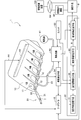
- FIG. 1 is a block diagram schematically showing a dental instrument hanger according to a first embodiment of the present invention. It is a schematic diagram which shows an example of the reading log
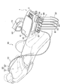
- the dental instrument hanger 1 includes a unit main body 3 and a hanger portion 10 provided on the unit main body 3.
- the dental instrument hanger 1 is supported by the arm unit 70.
- the arm part 70 is connected with the base of the patient chair 80, and other dental treatment equipment.
- the dental treatment equipment includes, for example, an autocuran (automatic water faucet), a spiton, a surgical light, a vacuum, etc., but illustration and description thereof are omitted.
- the dental instrument hanger 1 usually includes a doctor instrument hanger and an assistant instrument hanger.
- a doctor instrument hanger is described as an example.
- the dental instrument hanger 1 shows the type supported by the arm part 70, it is not limited to this, According to use, such as the type installed in the stand etc. Various forms can be implemented.
- the hanger part 10 accommodates a plurality of dental instruments 20 in a detachable manner.
- the hanger part 10 has a plurality of holders 11, and the instruments 20 can be individually stored in the respective holders 11.
- the five holders 11 are displayed separately from the left, such as No. 1, No. 2,.
- the hanger unit 10 includes a hanger sensor 12 and a reader / writer (reading unit) 40.
- the attachment / detachment detection means 54, the drive circuit 52, and the control means 30 are built in the unit main body 3 (FIG. 1).
- each part will be described.
- the hanger sensor 12 is provided at a site where the instrument 20 of the hanger part 10 is mounted.
- the hanger sensor 12 detects attachment / detachment of the instrument 20 for each holder 11 of the hanger part 10.
- the first to fifth hanger sensors 12 are provided corresponding to the first to fifth holders 11.
- the hanger sensor 12 is composed of, for example, a reflective or transmissive optical sensor.
- the hanger sensor 12 is, for example, a reflection type optical sensor, when the reflected light from the instrument 20 is received when the optical path of the light irradiated in the holder 11 is blocked by the instrument 20, the instrument 20 Detect the presence of.
- the hanger sensor 12 detects that the instrument 20 has been taken out of the hanger portion 10 when no light is received.
- the hanger sensor 12 when the hanger sensor 12 is a transmissive optical sensor, the hanger sensor 12 detects that the instrument 20 has been taken out of the hanger portion 10 when receiving light irradiated in the holder 11. .
- the hanger sensor 12 detects the presence of the instrument 20.
- the hanger sensor 12 may be constituted by a magnetic sensor or a contact type sensor.
- the reader / writer (reading means) 40 reads information such as identification information from the wireless tag T in a state where the instrument 20 to which the wireless tag T is attached in advance is housed in the hanger unit 10. In the present embodiment, the reader / writer 40 writes predetermined information to the wireless tag T.
- the reader / writer 40 is assumed to be an RFID (Radio Frequency Identification) reader / writer.
- the reader / writer (sensor main body) 40 includes an antenna 42 connected to the sensor main body by a lead wire 44, and the antenna 42 is disposed in the hanger portion 10. Thereby, the antenna 42 can detect the wireless tag T attached to the instrument 20 attached to the hanger part 10 with good directivity and read the identification information by the sensor body.
- the monitoring area of the antenna 42 is provided so as to include all the holders 11. That is, the antenna 42 is one large antenna and is built in the hanger part 10 so as to cover all the holders 11.
- the antenna 42 of the reader / writer 40 communicates with the wireless tag T and causes the reader / writer 40 to read information from the wireless tag T. It was decided.
- the antenna 42 communicates with the wireless tag T even when the main power is turned on.
- the attachment / detachment detection means 54 detects taking-out of the instrument 20 from the hanger part 10 and latching to the hanger part 10.
- the attachment / detachment detection means 54 controls the drive circuit 52 so that only one instrument 20 is driven with priority given to what is taken out earlier.
- This attachment / detachment detection means 54 is provided in a general dental unit.
- the attachment / detachment detection means 54 includes a detection circuit that detects attachment / detachment of the instrument 20 in response to a signal from the hanger sensor 12 and latches only detection information corresponding to the instrument 20 that is first taken out. Etc. are provided.
- the attachment / detachment detection means 54 can identify from the information of each hanger sensor 12 which holder 11 of the hanger part 10 is actually used by the surgeon.
- the attachment / detachment detection unit 54 detects attachment / detachment of the instrument 20
- the attachment / detachment detection unit 54 outputs a signal for starting the reader / writer 40 to the reader / writer 40.
- the attachment / detachment detection means 54 notifies the reading history detection means 32 of attachment / detachment of the instrument 20 in order to identify from which holder 11 of the hanger part 10 the instrument 20 has been taken out. To do.
- the drive circuit 52 is a known means for driving the instrument 20 and includes an electric circuit, a switching valve, and the like.
- the drive circuit 52 includes a power supply circuit (micromotor operating power, illumination power, heating power), an air circuit (pressurized air for driving the turbine, tip air for generating fog), a water supply circuit, and the like. .
- the water supply circuit is a circuit common to a plurality of instruments 20 and is connected to only one instrument 20 that is in use.
- the drive circuits that individually drive the instruments 20 are collectively referred to as a drive circuit 52.
- the drive circuit 52 operates when a drive instruction for driving the instrument 20 taken out from the hanger unit 10 is input. This drive instruction is input to the drive circuit 52 by the switch 53.
- the switch 53 is a switch common to the plurality of instruments 20, for example, a foot switch operated by pushing with a foot.
- the drive circuit 52 is connected to an external drive source 51.
- the drive source 51 schematically shows a power source, an air source, a water source, and the like.
- the instrument 20 includes, for example, a handpiece 21 and a connection portion 22.
- a hose 23 is connected to the connection portion 22, and the hose 23 is connected to a drive source 51 via a drive circuit 52.
- the handpiece 21 is detachable with respect to the connection portion 22, and a wireless tag T is attached thereto.
- the handpiece 21 is connected to the hose 23 and cannot be attached or detached.
- the wireless tag T can read and write information by contactless communication with the reader / writer 40.
- the wireless tag T is, for example, an RFID tag.
- a unique ID identification information
- This identification information may be used as identification information for identifying the instrument 20 to which the wireless tag T is attached.
- various products such as those having a size of 1 cmm or less and those for medical use are commercially available, but it is preferable to use a tag having a size of about several mm.
- a commercially available product has a storage capacity (for example, 16 bytes) for storing the unique ID and a readable / writable storage capacity (for example, 112 bytes).
- the control unit 30 includes an identification information storage unit 31, a reading history detection unit 32, an identification information specifying unit 33, and a usage information generation unit 34.
- the control unit 30 includes, for example, a CPU (Central Processing Unit), a RAM (Random Access Memory), a ROM (Read Only Memory), and the like.
- the identification information accumulating unit 31 accumulates identification information of all the wireless tags T in the hanger unit 10 read by the reader / writer 40 in a database for each reading history, and is configured by a general memory, for example. .
- FIG. 3 is a diagram schematically illustrating an example of the storage structure of the identification information storage unit 31.
- the oldest reading history database DB is arranged on the leftmost side, and the reading history database DB is arranged in time order.
- the identification information storage unit 31 may execute a deletion process such as deleting a new DB from an old one while leaving a predetermined number.
- a deletion process such as deleting a new DB from an old one while leaving a predetermined number.
- the reading history detection unit 32 When a driving instruction for driving the instrument 20 is input, the reading history detection unit 32 refers to the identification information storage unit 31 and the latest reading history and the hanger unit 10 for the identification information of all the wireless tags T. The reading history before the instrument 20 taken out from the hanger unit 10 is detected.
- the reader / writer 40 reads information from the wireless tag T every time the hanger sensor 12 detects the attachment / detachment of the instrument 20. Therefore, when the instrument 20 is taken out from the hanger part 10, the reader / writer 40 reads the ID from the wireless tags T attached to all the instruments 20 attached to the hanger part 10 at that time. . All IDs read at this time become the latest reading history when a driving instruction for driving the instrument 20 is input.
- the reading history before the instrument 20 is taken out of the hanger unit 10 is a reading history that includes other IDs in addition to all IDs included in the latest reading history. Therefore, for example, the reading history detection unit 32 sorts the reading histories stored in the identification information storage unit 31 in order from the latest to the past, and the number of IDs is, for example, 1 compared with the latest reading history. The reading history at the time when only one more is searched. Thereby, the reading history detecting means 32 can detect the reading history before the instrument 20 is taken out of the hanger part 10.
- the reading was performed from the radio tags T attached to all the instruments 20.
- the ID is 001, 002, 003, 004.
- the number of IDs in this reading history is four.
- the reading history detection unit 32 reads the reading history at the time (TIME5) taken out and the time when the number of IDs was four ( Detect the reading history at TIME4).
- the reading history detection unit 32 outputs the two detected reading histories to the identification information specifying unit 33.
- the reading history detection unit 32 detects the reading history when receiving the notification of attachment / detachment of the instrument 20 from the attachment / detachment detection unit 54 regardless of whether or not a drive instruction is input. Therefore, even when the instrument 20 is replaced, it is possible to specify the ID of the wireless tag T attached to the instrument 20 taken out from the hanger unit 10.
- the identification information specifying means 33 determines the difference between the two reading histories detected by the reading history detection means 32, and uses the difference as the identification information (ID of the wireless tag T attached to the instrument 20 for which the drive instruction has been given. ).
- the identification information specifying unit 33 can specify the identification information of the instrument 20 that is being taken out of the hanger unit 10 and being driven by the information read by the reader / writer 40.
- the identification information specifying unit 33 outputs the identification information (ID) of the wireless tag T attached to the driven instrument 20 to the usage information generating unit 34.
- the usage information generating unit 34 generates usage information for specifying that the instrument 20 to which the wireless tag T identified by the identification information (ID) specified by the identification information specifying unit 33 is attached has been used.
- the usage information includes, for example, the date and time of use, the usage time zone, the number of days used, etc., of the instrument 20 to which the wireless tag T is attached.
- the usage information generating unit 34 includes the instrument 20 to which the wireless tag T identified by the ID identified by the identification information identifying unit 33 is attached from the drive circuit 52 that drives the instrument 20. Drive information is extracted.
- the usage information generating unit 34 generates a cumulative usage time of the instrument 20 based on the extracted drive information.
- the cumulative usage time of the instrument means the driving time of the instrument.
- the surgeon uses the instrument 20 while switching the switch 53 between ON and OFF. Of the ON / OFF time information of the switch 53, the time when the operator presses the switch 53 and the time during which the instrument 20 is actually driven (ON time) is accumulated is the accumulated usage time.
- ON / OFF time information of compressed air when the surgeon holds the handpiece 21 can be obtained from the extracted drive information. Specifically, information that the blades (impellers) of the turbine have been rotating, for example, for 3 minutes is obtained as the accumulated usage time. Similarly, the time for pouring water into the cutting bar and the affected part can be obtained.
- the reader / writer 40 writes the usage information in the wireless tag T attached to the instrument in which the usage information is generated. For this reason, for example, the reader / writer 40 requests usage information by notifying the usage information generation unit 34 of the ID when reading the ID from the wireless tag T. Then, the usage information generation unit 34 determines whether usage information has already been generated for the same ID as the ID received by the request, and notifies the reader / writer 40 if the corresponding usage information exists.
- the usage information may be notified to the reader / writer 40 together with the ID. In that case, if the ID read from the wireless tag T is the same as the ID notified from the usage information generating means 34, the reader / writer 40 may write the notified usage information into the wireless tag T.
- the information that is read and written for the instrument 20 includes information indicating the type of instrument, maintenance information required for use, and the like in addition to the usage information.
- the handpiece needs to be autoclaved (sterilized) or lubricated periodically on the rotary bearing portion for maintenance, and the maintenance information can also be written.
- some turbine blades (impellers) have a cartridge style, so information about the cartridge may be written.
- FIG. 4 shows an example of information that is read and written to manage the instrument.
- the contents to be written in the wireless tag T include the model number, shipping date, last use date, use day, lubrication count, sterilization count, use time, repair date, latest (or oldest) data storage location, lubrication date and time.
- the sterilization date and time, the number of repairs, the number of turbine cartridge replacements, and the turbine cartridge replacement date and time are illustrated.
- the model number is a generic name for information for identifying the instrument itself (type, function, model number).
- the types are classified as, for example, a turbine, a handpiece, a syringe, a scaler, and the like.
- the information for identifying the function varies depending on the type of instrument. For example, if the type of instrument is a turbine, the information for identifying the function includes the number of rotations, information on whether or not a lighting LED is provided at the tip, and the like.
- the reader / writer 40 recognizes only the ID of the wireless tag T, and stores and manages it in the storage means inside the unit body 3 or a server on the communication network. Also good.
- the identification information storage means 31 may be used as the storage means inside the unit main body 3.
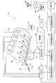
- a communication unit 91 is built in the table 60 on the unit body 3, and an information terminal device 92 is provided on the table 60.
- the communication unit 91 transmits / receives information to / from the information terminal device 92.
- Information transmitted / received here is information obtained from the wireless tag T or the like.
- the communication unit 91 transmits information to the information terminal device 92 by short-range wireless communication under the control of the control unit 30.
- the short-range wireless communication standard includes, for example, a wireless local area network (LAN) such as Wi-Fi (registered trademark), Bluetooth (registered trademark), and ZigBee (registered trademark).
- the communication unit 91 transmits / receives information to / from an external device via the information terminal device 92 and the communication network.
- the communication unit 91 may transmit / receive information to / from an external device via a communication network such as the Internet without the information terminal device 92 being interposed.
- the information terminal device 92 is a device that can communicate with a communication network such as the Internet.
- a communication network such as the Internet.
- the information terminal device 92 for example, a commercially available smartphone or tablet PC can be used.
- the information terminal device 92 also functions as a display that displays received information. Thereby, the staff of the dental clinic such as a doctor can check the maintenance information displayed on the display of the information terminal device 92.
- the antenna 42 of the reader / writer 40 communicates with the wireless tags T attached to the four instruments 20 respectively.
- the identification information storage unit 31 stores the identification information (ID) of the wireless tags T attached to all the instruments 20 stored in the hanger unit 10 via the reader / writer 40.
- the antenna 42 of the reader / writer 40 communicates with the wireless tag T only when the hanger sensor 12 reacts.
- the attachment / detachment detecting means 54 takes out any instrument 20 whose ID is unknown from the hanger part 10 in response to a signal from the third hanger sensor 12. Detect that. Then, the attachment / detachment detection means 54 outputs a signal for starting the reader / writer 40 to the reader / writer 40.
- the antenna 42 of the reader / writer 40 performs communication with the wireless tags T attached to the remaining three instruments 20 attached to the holders 11.
- the ID read by the reader / writer 40 is newly accumulated in the identification information accumulating means 31. Thereby, for example, in FIG. 3, the same ID as the reading history when the time is TIME5 is stored.
- the dental instrument hanger 1 determines which instrument 20 is compared to when the main power is turned on based on the difference between the reading history information at this time and the reading history information when the main power is turned on. Can be identified from the hanger part 10. That is, the dental instrument hanger 1 can identify the ID of the wireless tag T attached to the instrument 20 taken out. However, even if the instrument 20 is taken out of the hanger part 10, the instrument 20 is not always driven by the switch 53. For example, the handpiece 21 at the tip of the instrument 20 may be replaced.
- the handpiece 21 is replaced as follows. This is because operation is assumed. For example, an air turbine handpiece having a maximum rotational speed of 300,000 revolutions per minute was prepared, but in reality, an air turbine handpiece having 400,000 revolutions per minute is assumed to be used.
- the antenna 42 of the reader / writer 40 is connected to the radio tags T attached to all the instruments 20 housed in the hanger unit 10. Each communicates. Further, when the reader / writer 40 reads the ID (for example, “003”) from the wireless tag T attached to the instrument 20 accommodated in the third holder 11, for example, the ID is used as the usage information generation unit 34. Request usage information by notifying. Then, the usage information generation unit 34 notifies the reader / writer 40 of usage information corresponding to the read ID. Then, the reader / writer 40 writes the notified usage information in the wireless tag T identified by the corresponding ID.
- the ID for example, “003”
- the dental instrument hanger 1 includes the antenna 42 connected to the reader / writer 40 in the hanger unit 10. Therefore, the antenna 42 can read the ID from the wireless tag T attached to the instrument 20 in a state where the instrument 20 is stored in the holder 11 of the hanger unit 10. Thereby, a sufficient time for the reader / writer 40 to read information from the wireless tag T is secured, and the possibility of erroneous recognition is reduced. Therefore, the usage information generating unit 34 can accurately acquire the cumulative usage time of the individual instrument 20 based on the information extracted from the drive circuit 52.
- the reader / writer 40 is made to read information from the wireless tag T every time when the attachment / detachment of the instrument 20 is detected. Can be achieved. Moreover, in the dental instrument hanger 1 of this embodiment, since the one big antenna 42 is provided so that the monitoring area
- the present invention is not limited to these embodiments, and can be carried out without changing the gist thereof.
- “regular” means that the time is determined in advance, and the same time interval (every second or the like) may be used, or different time intervals may be used.
- the reader / writer 40 since the communication time between the reader / writer antenna and the IC tag is about several ms, the reader / writer 40 reads out several times, tens of times, or hundreds of times per second. Can do. That is, in the first modification, the reader / writer 40 periodically reads out at a time interval of approximately 1 second or less. Therefore, in comparison with the technique in which information is read from the wireless tag T every time the instrument 20 is detached, In a normal sense, it can be said to be a method of reading information from beginning to end.
- the reading history detection unit 32 refers to the identification information storage unit 31 periodically at a predetermined frequency, not only when a driving instruction for driving the instrument 20 is input, For identification information, the latest reading history is detected.
- the frequency at which the reading history detection unit 32 refers to the identification information storage unit 31 is assumed to be equal to or higher than the frequency of reading the wireless tag T by the reader / writer 40, for example, every second.
- the upper limit may be a time interval such that the instrument 20 is taken out from the hanger part 10.
- the reader / writer 40 reads out the wireless tag T every 0.5 seconds, for example, while the identification information storage unit 31 stores the reading history, while the reading history detection unit 32 stores the identification information storage unit every second, for example. 31 may be referred to.
- the antenna 42 periodically communicates with the wireless tag T when the wireless tag T can be detected in the vicinity after the main power is turned on. Then, the identification information accumulating means 31 stores the identification information (ID) of the radio tags T attached to all the instruments 20 stored in the hanger part 10 via the reader / writer 40, respectively.
- ID identification information
- a database of the same reading history as the time (TIME 4) when the four instruments 20 are mounted on the hanger unit 10 is used, for example. It accumulates every 0.5 seconds.
- the wireless tag T attached to the instrument 20 moves away from the monitoring area of the antenna 42.
- the same reading history database as the time (TIME 5) when the three instruments 20 are mounted on the hanger unit 10 is set to 0. 0, for example. Accumulate every 5 seconds.
- the reading history detection unit 32 can easily detect the wireless tag T that is away from the monitoring area of the antenna 42, that is, the ID that has disappeared from the database of the identification information storage unit 31.
- the operation when the switch 53 is pressed is the same as in the first embodiment.
- the structure of the hanger sensor 12 and the attachment / detachment detection means 54 can be abbreviate
- a position detection sensor that detects the position of the wireless tag T attached to the instrument 20 accommodated in the holder 11 may be further provided.
- the position detection sensor may be of a type that detects the position of the wireless tag T by communicating with the wireless tag T.
- a commercially available small antenna can be used. Note that the position detection sensor is provided separately from the antenna 42.
- a plurality of position detection sensors are prepared, and are respectively provided at predetermined positions in the hanger part 10.
- the number of position detection sensors may be smaller than the number of all holders 11 (for example, 5) (for example, 4).
- Each wireless tag T in the hanger unit 10 is calibrated in advance on the reader / writer 40 side with respect to each position where the position detection sensor is disposed and the position information of the wireless tag T obtained from the position detection sensor. Can be recognized where. Therefore, according to the second modification, by using both the information detected by the plurality of position detection sensors and the information read from the wireless tag T by the reader / writer 40, the ID number of the holder 11 in the hanger unit 10 is determined. It is possible to grasp whether the instrument 20 to which the wireless tag T is attached is stored.
- the dental instrument hanger 1B which concerns on 2nd Embodiment of this invention is demonstrated.
- symbol is attached
- the dental instrument hanger 1B includes a plurality of antennas 42 connected to the reader / writer 40 in each of the plurality of holders 11 of the hanger portion 10B. That is, the first holder 11 is provided with the first antenna 42, and the second holder 11 is provided with the second antenna 42.
- the plurality of small antennas 42 are built in the hanger portion 10B.
- the attachment / detachment detection unit 54 does not notify the reading history detection unit 32 of attachment / detachment of the instrument 20.
- the operation of the dental instrument hanger 1B will be described on the assumption that a total of four instruments 20 are stored and prepared in advance in the first to fourth holders 11 of the hanger portion 10B.
- the antenna 42 of the reader / writer 40 communicates with the wireless tag T only when the hanger sensor 12 reacts, as in the first embodiment.
- the antenna 42 in the vicinity of the holder 11 where the hanger sensor 12 that has reacted is communicated with the wireless tag T.
- the attachment / detachment detection means 54 outputs a signal for starting the reader / writer 40 to the reader / writer 40 in accordance with a signal from the third hanger sensor 12.
- the third antenna 42 cannot detect the wireless tag T in the vicinity, but the other antennas 1, 2, 4 and 4 are not connected to the nearby wireless tag T. Can be detected respectively.
- the IDs read by the reader / writer 40 from, for example, three wireless tags T in the hanger unit 10B are newly added and stored in the identification information storage unit 31, respectively. Thereby, for example, in FIG. 3, IDs similar to the reading history of TIME5 are stored.
- the operation when the switch 53 is pressed is the same as in the first embodiment.
- the dental instrument hanger 1B of the second embodiment since the communication distance between the antenna 42 and the wireless tag T can be short, an HF band antenna with a small output can be used. Moreover, according to the dental instrument hanger 1B of 2nd Embodiment, the power saving of the reader / writer 40 can be achieved similarly to 1st Embodiment.
- each antenna 42 of the reader / writer 40 may be modified so as to periodically read identification information (ID) from a nearby wireless tag T.
- ID identification information
- the hanger sensor 12 and the attachment / detachment detection means 54 are not provided.
- the reading history detecting means 32 is attached to all the instruments 20 by referring to the identification information accumulating means 31 periodically at a predetermined frequency, not only at the time of inputting a driving instruction for driving the instruments 20.
- the latest reading history is detected. Since the other configuration is the same as that of FIG. 5, the drawing is omitted.
- the RFID tag T attached to the instrument 20 monitors the third antenna 42. Leave the area.
- the ID of the remote RFID tag T disappears from the database of the identification information storage means 31, but the antennas 42 in the vicinity of the other holders 11 respectively detect the adjacent RFID tags T in the monitoring area. Can continue. Therefore, the RFID tag T far from the monitoring area of the third antenna 42, that is, the ID disappeared from the database of the identification information storage unit 31 can be easily detected by the identification information specifying unit 33.
- the operation when the switch 53 is pressed is the same as in the first embodiment.
- the configuration of the hanger sensor 12 and the attachment / detachment detection means 54 can be omitted, and thus the manufacturing cost can be reduced.
- the second radio tag T2 may be attached to the instrument 20 together with the radio tag T, and both the tags may be read by the reader / writer 40.
- the wireless tag T (hereinafter referred to as the first wireless tag T for convenience) is attached to the handpiece 21, and the second wireless tag T ⁇ b> 2 is attached to the connection portion 22.
- the second wireless tag T2 may be attached to the end portion of the hose 23 on the side close to the connection portion 22.
- the second wireless tag T2 is, for example, an RFID tag, and at least a unique ID (identification information) provided in the second wireless tag T2 is written in advance.
- This identification information may be used as identification information for identifying the connection portion 22 to which the second wireless tag T2 is attached.
- the connection part 22 and the hose 23 of each instrument 20 shall be used as what is accommodated in the predetermined holder position in the hanger part 10B. That is, the connection part 22 and the hose 23 determined to be stored in the first holder 11 in advance are used so as not to be stored in the second holder 11 or the third holder 11.
- the identification information of the second wireless tag T2 is associated one-on-one with the identification information (for example, No. 1, No. 2,... No. 5,) for identifying the holder 11 of the hanger unit 10.
- holder identification information such as No. 1, No. 2,..., No. 5 may be written in the second wireless tag T2.
- the antenna 42 of the reader / writer 40 is identified from the first wireless tag T attached to the handpiece 21 attached to the holder 11 when the handpiece 21 and the connecting portion 22 are coupled in the hanger portion 10B. And the identification information is read from the second wireless tag T2 attached to the connection portion 22. Further, the antenna 42 is identified from the second wireless tag T2 attached to the connection portion 22 when the connection portion 22 is detached from the handpiece 21 and hooked to the holder 11 together with the hose 23 in the hanger portion 10B. Read information. When the antenna 42 for each holder 11 can read the identification information from the second wireless tag T2, the connecting portion 22 to which the second wireless tag T2 is attached is connected to the corresponding holder 11 being monitored by the hose 23. Acquires information that it is hooked together.
- the antenna 42 for each holder 11 can substitute the function of the hanger sensor 12 for detecting the attachment / detachment of the instrument 20 for each holder 11.
- the connection portion 22 and the hose 23 are not attached without the handpiece 21 of the instrument 20 being attached.
- the function of the hanger sensor 12 can be substituted even if it is the usage method which latches on the holder 11.
- the antenna 42 is installed in the hanger units 10 and 10B.
- the reader / writer 40 may be installed in the hanger unit 10 instead of the antenna 42.
- a plurality of reader / writers 40 may be installed in the hanger unit 10.
- the reader / writer 40 reads information from the wireless tag T and stores it in the identification information storage means 31. You may make it do.
- the reading history detection unit 32 detects the reading history accumulated in conjunction with the switch 53 being turned on as the latest reading history. Even if the switch 53 is switched to ON or OFF to drive or stop the instrument 20 that has been taken out, it is detected when it is turned on every time the switch is switched. The latest reading history related to the ID is the same.
- the method for detecting the reading history before the instrument 20 taken out from the hanger unit 10 is taken out from the hanger unit 10 is the same as the method described above.
- the communication unit 91 may transmit / receive the usage information generated by the usage information generation unit 34 to / from the information processing apparatus 100 via the communication network NW.
- the communication network NW is schematically illustrated including a wired communication network using a wired LAN, a communication network such as a wireless LAN and Bluetooth (registered trademark), and a network such as the Internet.
- the information processing apparatus 100 includes, for example, a general personal computer (PC) and a portable terminal device such as a tablet PC.
- the information processing apparatus 100 may be a receipt computer or a dental treatment facility capable of network communication.
- the information processing apparatus 100 includes, for example, a clinic in which the dental instrument hanger 1 is installed, other rooms in the dental clinic, a manufacturer of instruments, a call center that accepts orders and repairs of instruments, Or it is installed on the cloud.
- the dental instrument hanger 1 is connected to the information processing apparatus 100 on the call center or the cloud, for example, via the communication network NW, and transmits / receives the usage information generated by the usage information generation unit 34. . Thereby, maintenance management of the instrument 20 and automatic ordering of parts can be performed.
- the wireless tag T is attached to the surface of the main body of the handpiece 21 in the instrument 20
- the part to which the wireless tag T is attached is not limited to this.
- the wireless tag may be attached to a cutting or polishing tool that is detachably attached to the handpiece 21 such as an air turbine, a micromotor, or a scaler.
- the cutting or polishing tool is a handpiece equipment, and specifically includes the following tools (1), (2), and (3).
- a dental bar (bur) that is attached to an air turbine or micromotor to cut or polish teeth and restorations
- Reamer or file that expands the root canal by connecting to a root canal enlargement motor or smoothes the root canal wall
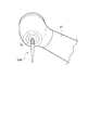
- FIG. 6 schematically shows a side of the head integrated with the main body of the handpiece 21 of the air turbine, for example, facing the affected area.
- the tool 20B is a cutting tool (dental bar).
- a wireless tag is attached to the base end side of the tool 20B.
- the wireless tag attached to the tool 20B is referred to as a third wireless tag T3 for convenience.
- the third wireless tag T3 is, for example, an RFID tag like the first wireless tag T, and at least a unique ID (identification information) provided in the third wireless tag T3 is written in advance. This identification information may be used as identification information for identifying the tool 20B to which the third wireless tag T3 is attached.
- the third RFID tag T3 is used for the same purpose as the first RFID tag T, that is, for generating usage information of the attached tool 20B.
- the dental instrument hanger 1 is identified from the third wireless tag T3 by the reader / writer 40 or the antenna 42 in the hanger unit 10.
- Information ID
- the dental instrument hanger 1 is connected to the information processing apparatus 100 on the call center or the cloud, for example, via the communication network NW, and the tool 20B is automatically ordered, etc. by transmitting / receiving the usage information of the tool 20B. It can be carried out.
- the third wireless tag T3 may be used in combination with the first wireless tag T and the second wireless tag T2.
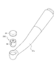
- the part to which the wireless tag is attached may be a cartridge housed in the head of a cartridge type dental turbine other than the tool 20B.
- FIG. 7 schematically shows an exploded perspective view of the head integrated with the main body of the handpiece 21C in the cartridge type air turbine.
- the cartridge 20C is conventionally known and is widely used in dental treatment.
- the cartridge 20 ⁇ / b> C is a housing in which a blade is provided around a rotating shaft on which a cutting or polishing tool to be rotated can be mounted, and a structure that can be rotated by compressed air is housed in a housing.
- the cartridge 20C is detachably housed in the head of the handpiece 21C and is covered by the lid 24.
- the cartridge 20C can be replaced.
- a contractor cleans the air circuit inside the cartridge and performs maintenance such as replacement of an O-ring and a bearing that are components of the cartridge.
- the cartridge 20C has a substantially cylindrical appearance, and a wireless tag is attached to a predetermined position on the outer peripheral surface thereof.
- the wireless tag attached to the cartridge 20C is referred to as a fourth wireless tag T4 for convenience.
- the fourth wireless tag T4 is, for example, an RFID tag, and at least a unique ID (identification information) provided in the fourth wireless tag T4 is written in advance. This identification information may be used as identification information for identifying the cartridge 20C to which the fourth wireless tag T4 is attached.
- the fourth wireless tag T4 is used for the same purpose as the first wireless tag T, that is, for generating usage information of the attached cartridge 20C.
- the dental instrument hanger 1 is identified from the fourth wireless tag T4 by the reader / writer 40 or the antenna 42 in the hanger unit 10.
- Information ID
- the dental instrument hanger 1 is connected to the information processing apparatus 100 on the call center or the cloud, for example, via the communication network NW, and sends and receives information on the use of the cartridge 20C. It is possible to automatically order the cartridge 20C.
- the fourth wireless tag T4 may be used in combination with the first wireless tag T, the second wireless tag T2, and the third wireless tag T3.
- the reading history detecting unit 32 sorts the reading histories accumulated in the identification information accumulating unit 31 in order from the latest to the past. What is necessary is just to search for the reading history at the time when the number of IDs is larger by the number of combined wireless tags (for example, two) than the latest reading history.
Landscapes
- Health & Medical Sciences (AREA)
- Life Sciences & Earth Sciences (AREA)
- Animal Behavior & Ethology (AREA)
- Veterinary Medicine (AREA)
- Public Health (AREA)
- General Health & Medical Sciences (AREA)
- Oral & Maxillofacial Surgery (AREA)
- Surgery (AREA)
- Engineering & Computer Science (AREA)
- Dentistry (AREA)
- Epidemiology (AREA)
- Molecular Biology (AREA)
- Medical Informatics (AREA)
- Heart & Thoracic Surgery (AREA)
- Biomedical Technology (AREA)
- Pathology (AREA)
- Nuclear Medicine, Radiotherapy & Molecular Imaging (AREA)
- Physics & Mathematics (AREA)
- Electromagnetism (AREA)
- Water Supply & Treatment (AREA)
- Dental Tools And Instruments Or Auxiliary Dental Instruments (AREA)
Abstract
La présente invention réduit les erreurs de reconnaissance dans la détection de l'utilisation d'un instrument. Un dispositif de suspension d'instrument dentaire (1) de l'invention comporte, stocké dans une partie de suspension (10), un corps d'un dispositif de lecture/écriture (40) pour lire, à partir d'une étiquette sans fil (T), des informations d'identification tandis qu'un instrument (20) avec l'étiquette sans fil ayant été préalablement fixé à celle-ci est logé dans la partie de suspension, ou une antenne (42) connectée au corps, et est pourvu de : un moyen d'accumulation d'informations d'identification (31) qui accumule les informations d'identification lues dans une base de données pour chaque enregistrement de lecture ; un moyen de détection d'enregistrement de lecture (32) qui référence le moyen d'accumulation d'informations d'identification lors de la réception d'une entrée d'une instruction de commande, et détecte à la fois le dernier enregistrement de lecture et un enregistrement de lecture enregistré avant que l'instrument soit retiré de la partie de suspension ; un moyen de spécification d'informations d'identification (33) qui détermine des différences entre les deux historiques de lecture, et spécifie des différences en tant qu'informations pour identifier l'étiquette sans fil attachée à l'instrument auquel l'instruction de commande a été donnée ; et un moyen de génération d'informations d'utilisation (34) qui génère des informations concernant l'utilisation dudit instrument.
Priority Applications (3)
| Application Number | Priority Date | Filing Date | Title |
|---|---|---|---|
| US16/083,083 US11219571B2 (en) | 2016-06-01 | 2017-04-24 | Dental instrument hanger |
| CN201780033511.5A CN109195549B (zh) | 2016-06-01 | 2017-04-24 | 牙科器械挂架 |
| EP17806238.6A EP3395291B1 (fr) | 2016-06-01 | 2017-04-24 | Dispositif de suspension pour instrument dentaire |
Applications Claiming Priority (2)
| Application Number | Priority Date | Filing Date | Title |
|---|---|---|---|
| JP2016-110411 | 2016-06-01 | ||
| JP2016110411A JP6306642B2 (ja) | 2016-06-01 | 2016-06-01 | 歯科用インスツルメントハンガー |
Publications (1)
| Publication Number | Publication Date |
|---|---|
| WO2017208678A1 true WO2017208678A1 (fr) | 2017-12-07 |
Family
ID=60478234
Family Applications (1)
| Application Number | Title | Priority Date | Filing Date |
|---|---|---|---|
| PCT/JP2017/016220 WO2017208678A1 (fr) | 2016-06-01 | 2017-04-24 | Dispositif de suspension pour instrument dentaire |
Country Status (5)
| Country | Link |
|---|---|
| US (1) | US11219571B2 (fr) |
| EP (1) | EP3395291B1 (fr) |
| JP (1) | JP6306642B2 (fr) |
| CN (1) | CN109195549B (fr) |
| WO (1) | WO2017208678A1 (fr) |
Cited By (1)
| Publication number | Priority date | Publication date | Assignee | Title |
|---|---|---|---|---|
| WO2020055707A1 (fr) * | 2018-09-14 | 2020-03-19 | Covidien Lp | Systèmes robotiques chirurgicaux et procédés de suivi de l'utilisation d'instruments chirurgicaux de ces derniers |
Families Citing this family (8)
| Publication number | Priority date | Publication date | Assignee | Title |
|---|---|---|---|---|
| EP3202387A1 (fr) * | 2016-02-03 | 2017-08-09 | XO Care A/S | Pont d'instrument dentaire avec nouvel affichage |
| JP6968035B2 (ja) * | 2018-06-20 | 2021-11-17 | 株式会社モリタ製作所 | 医療用診療装置 |
| JP2019216994A (ja) * | 2018-06-20 | 2019-12-26 | 株式会社モリタ製作所 | 医科歯科用ハンドピース |
| DE102019102685A1 (de) * | 2019-02-04 | 2020-08-06 | Aesculap Ag | System, Vorrichtungen und Verfahren zur Identifizierung eines medizintechnischen Werkzeugs |
| US11185389B2 (en) | 2019-04-17 | 2021-11-30 | A-Dec, Inc. | Dental flow control adjuster with operation indicator |
| JP6917071B2 (ja) * | 2019-07-09 | 2021-08-11 | 株式会社吉田製作所 | 歯科用ハンドピース、歯科用ハンドピース管理システム及び歯科用ハンドピース用光ファイバーの交換方法 |
| DE102019122349A1 (de) * | 2019-08-20 | 2021-02-25 | Aesculap Ag | Integrierte RFID -Tag - Halterung |
| IT202100022874A1 (it) * | 2021-09-03 | 2023-03-03 | Btc S R L | Riunito medico |
Citations (3)
| Publication number | Priority date | Publication date | Assignee | Title |
|---|---|---|---|---|
| JP2011182849A (ja) * | 2010-03-05 | 2011-09-22 | Morita Mfg Co Ltd | 診療装置およびそのインスツルメントの管理制御方法 |
| JP2012203572A (ja) * | 2011-03-24 | 2012-10-22 | Morita Mfg Co Ltd | 医療用診療装置 |
| JP2015142690A (ja) * | 2014-01-31 | 2015-08-06 | 株式会社吉田製作所 | 歯科診療システム |
Family Cites Families (13)
| Publication number | Priority date | Publication date | Assignee | Title |
|---|---|---|---|---|
| DE4409862C2 (de) * | 1994-03-22 | 1997-06-05 | Siemens Ag | Zahnärztliche Einrichtung mit ein oder mehreren unterschiedlich konfigurierten Instrumenten |
| US6017354A (en) * | 1996-08-15 | 2000-01-25 | Stryker Corporation | Integrated system for powered surgical tools |
| EP1392193B1 (fr) * | 2001-06-07 | 2009-12-09 | Kaltenbach & Voigt GmbH | Instrument medical ou de medecine dentaire et/ou appareil d'alimentation et/ou appareil de soin pour ledit instrument medical ou de medecine dentaire |
| US20060042631A1 (en) * | 2004-08-31 | 2006-03-02 | Martin James F | Apparatus to deliver oxygen to a patient |
| FR2891132B1 (fr) * | 2005-09-29 | 2007-11-30 | Fkg Dentaire Sa | Procede et dispositif d'identification et de controle d'un instrument medical |
| DE102007008366B4 (de) * | 2007-02-16 | 2008-11-13 | Sirona Dental Systems Gmbh | Behandlungseinheit mit Sensorsystem zur Erkennung dentaler Handinstrumente und Verfahren zur Kontrolle und Identifikation eines Handinstruments |
| GB2448421A (en) * | 2007-04-11 | 2008-10-15 | Forth Photonics Ltd | Workstation for a colposcopy |
| CN101564342A (zh) * | 2008-04-21 | 2009-10-28 | 张任秀 | 新型口腔综合治疗椅手机挂架结构 |
| JP2012524643A (ja) * | 2009-05-08 | 2012-10-18 | ザ ジレット カンパニー | パーソナルケアシステム、製品、及び方法 |
| EP2327370A3 (fr) * | 2009-11-25 | 2011-12-28 | W & H Dentalwerk Bürmoos GmbH | Dispositif d'accouplement dans une pièce à main médicale, en particulier dentaire |
| US20180092710A1 (en) * | 2016-09-30 | 2018-04-05 | Kerr Corporation | Electronic tool recognition system for dental devices |
| US20180256287A1 (en) * | 2017-03-13 | 2018-09-13 | Kerr Corporation | Tool rfid recognition system for dental devices |
| US10881490B2 (en) * | 2017-06-08 | 2021-01-05 | Kavo Dental Technologies, Llc | Handpiece maintenance system and dental instruments for predictive maintenance |
-
2016
- 2016-06-01 JP JP2016110411A patent/JP6306642B2/ja active Active
-
2017
- 2017-04-24 US US16/083,083 patent/US11219571B2/en active Active
- 2017-04-24 CN CN201780033511.5A patent/CN109195549B/zh active Active
- 2017-04-24 WO PCT/JP2017/016220 patent/WO2017208678A1/fr active Application Filing
- 2017-04-24 EP EP17806238.6A patent/EP3395291B1/fr active Active
Patent Citations (3)
| Publication number | Priority date | Publication date | Assignee | Title |
|---|---|---|---|---|
| JP2011182849A (ja) * | 2010-03-05 | 2011-09-22 | Morita Mfg Co Ltd | 診療装置およびそのインスツルメントの管理制御方法 |
| JP2012203572A (ja) * | 2011-03-24 | 2012-10-22 | Morita Mfg Co Ltd | 医療用診療装置 |
| JP2015142690A (ja) * | 2014-01-31 | 2015-08-06 | 株式会社吉田製作所 | 歯科診療システム |
Cited By (2)
| Publication number | Priority date | Publication date | Assignee | Title |
|---|---|---|---|---|
| WO2020055707A1 (fr) * | 2018-09-14 | 2020-03-19 | Covidien Lp | Systèmes robotiques chirurgicaux et procédés de suivi de l'utilisation d'instruments chirurgicaux de ces derniers |
| CN112702967A (zh) * | 2018-09-14 | 2021-04-23 | 柯惠Lp公司 | 手术机器人系统和跟踪其手术器械的使用的方法 |
Also Published As
| Publication number | Publication date |
|---|---|
| JP2017213277A (ja) | 2017-12-07 |
| EP3395291A4 (fr) | 2019-06-26 |
| US11219571B2 (en) | 2022-01-11 |
| US20190070055A1 (en) | 2019-03-07 |
| CN109195549B (zh) | 2020-11-06 |
| EP3395291B1 (fr) | 2020-01-29 |
| CN109195549A (zh) | 2019-01-11 |
| JP6306642B2 (ja) | 2018-04-04 |
| EP3395291A1 (fr) | 2018-10-31 |
Similar Documents
| Publication | Publication Date | Title |
|---|---|---|
| JP6306642B2 (ja) | 歯科用インスツルメントハンガー | |
| US9510740B2 (en) | Auto recognition of a shaver blade for medical use | |
| US9367062B2 (en) | System and method for operational data retrieval from a power tool | |
| JP6325826B2 (ja) | 歯科診療システム | |
| US20100176925A1 (en) | Method and Apparatus for Surgical Instrument Identification | |
| JP2007014463A (ja) | 自動調剤装置及び自動調剤装置における薬瓶の管理方法 | |
| CN112912028B (zh) | 保持设备和产品监视系统 | |
| JP2011204205A (ja) | 医療機器情報管理システム | |
| US11179217B2 (en) | Medical treatment instrument temperature information management device | |
| US11969299B2 (en) | Tool having a working end determining device in the shaft region | |
| US20230149027A1 (en) | Drill bit data management for penetration-monitoring drill | |
| JP2005237586A (ja) | 手術用器具の管理方法および管理システム | |
| JP2019216996A (ja) | 医療用診療装置 | |
| US20220096201A1 (en) | System, devices, and method for identifying a medical tool | |
| US10905523B2 (en) | Lubrication information management device for dentistry | |
| JP7127828B2 (ja) | 手指衛生管理システム | |
| JP7089243B2 (ja) | 吐出操作検出装置および手指衛生管理システム | |
| CN114401693A (zh) | 制造牙科修复体的方法 | |
| JP2019216997A (ja) | 診療器具、処理装置、診療装置、および管理システム | |
| CN108324320A (zh) | 一种超声探头连接系统及其方法 |
Legal Events
| Date | Code | Title | Description |
|---|---|---|---|
| WWE | Wipo information: entry into national phase |
Ref document number: 2017806238 Country of ref document: EP |
|
| ENP | Entry into the national phase |
Ref document number: 2017806238 Country of ref document: EP Effective date: 20180724 |
|
| NENP | Non-entry into the national phase |
Ref country code: DE |